JP4403336B2 - Electronic map display device, navigation device, storage medium, and electronic map display method - Google Patents
Electronic map display device, navigation device, storage medium, and electronic map display method Download PDFInfo
- Publication number
- JP4403336B2 JP4403336B2 JP2000133267A JP2000133267A JP4403336B2 JP 4403336 B2 JP4403336 B2 JP 4403336B2 JP 2000133267 A JP2000133267 A JP 2000133267A JP 2000133267 A JP2000133267 A JP 2000133267A JP 4403336 B2 JP4403336 B2 JP 4403336B2
- Authority
- JP
- Japan
- Prior art keywords
- data
- image
- symbol mark
- image data
- electronic map
- Prior art date
- Legal status (The legal status is an assumption and is not a legal conclusion. Google has not performed a legal analysis and makes no representation as to the accuracy of the status listed.)
- Expired - Fee Related
Links
Images


Landscapes
- Navigation (AREA)
- Processing Or Creating Images (AREA)
- Traffic Control Systems (AREA)
- Instructional Devices (AREA)
Description
【0001】
【発明の属する技術分野】
本発明は、電子地図情報を表示する電子地図表示装置、および電子地図情報を用いるナビゲーション装置、および記録媒体に関する。
【0002】
【従来の技術】
近年、地図情報を電子化し、パーソナルコンピュータ等の画面上に表示して利用できるようになっている。また、ナビゲーション装置等においては、電子化した地図情報を用い、現在位置や移動ルート等を地図に重ね合わせてモニタ上に表示している。
【0003】
このような電子地図情報においては、例えば官公庁、役所、病院、その他建造物や会社、店舗等、目印となるもの(ランドマーク)が電子地図上に表示されることが多い。さらに、ユーザー側において、例えば店舗や会社、各種施設、知人の家等、特定の場所の位置情報を登録しておき、その位置をいわゆるシンボルマーク等によって電子地図上に表示できるようになっているものも有る。
【0004】
例えばナビゲーション装置では、食事施設、観光施設、レジャー施設等、様々な種類のシンボルマークが予め記憶されている。より具体的には、例えばレジャー(スポーツ)系の施設用のシンボルマークとして、図9に示すような、野球のシンボルマークM1、ゴルフのシンボルマークM2、テニスのシンボルマークM3等がある。
ユーザー側は、これらシンボルマークのリスト中から、対象となる場所を象徴するようなシンボルマークを選び、これを電子地図上の任意の位置に登録するのである。このようにして登録されたシンボルマークは、ナビゲーション画面上の電子地図に表示され、これによって設定した対象の存在、位置およびその種別を一目で認識することができ、ナビゲーション装置の視認性を高めている。そして、これらのシンボルマークは、ユーザーが、例えば目的地の設定を行うとき等に、その操作性を向上させることもできるようになっている。
【0005】
【発明が解決しようとする課題】
しかしながら、従来、電子地図表示装置やナビゲーション装置等に予め用意(記憶)されているシンボルマークは、あくまでも対象となるものの「種別」を表現するに過ぎなかった。したがって、例えばゴルフ場をシンボルマークM1で登録した場合、登録した全てのゴルフ場が同じシンボルマークM1で表示され、その識別が困難となっていた。
このため、一つの「種別」に対し、複数のシンボルマークが用意されることも有る。例えば図9に示したように、「人の顔」のシンボルマークとして複数のシンボルマークM4、M5、M6が用意されているのである。これにより、例えば「知人の家」に対して、これら複数のシンボルマークM4、M5、M6を用いることができ、これにより識別が容易になるかと思えるが、実際には、使用できるマークの数は当然限られており、さらには、どのシンボルマーク(例えばシンボルマークM5)が、どの人物を示しているか、一目で認識することは困難である。
このように、従来のシンボルマークの利用形態では、認識性および使い勝手が良いとは必ずしも言えなかったのが現状である。
【0006】
本発明は、このような技術的課題に基づいてなされたもので、より認識しやすく、かつ使い勝手に優れた電子地図表示装置、ナビゲーション装置、および記録媒体を提供することを目的とする。
【0007】
【課題を解決するための手段】
かかる目的のもと、本発明は、電子情報からなる地図データに基づき電子地図を表示する電子地図表示装置であって、外部から画像データを取り込む画像データ取り込み手段と、前記画像データ取り込み手段で取り込んだ前記画像データに基づき画像を表示する画像表示手段と、前記画像表示手段に表示された前記画像の一部を切り出してマーク用データを生成するマーク用データ生成手段と、前記マーク用データに基づく画像を、シンボルマークとして前記電子地図上に表示するシンボルマーク表示手段と、を備えることを特徴としている。
このような構成とすれば、外部から取り込んだ画像データの一部を切り出してシンボルマークを生成し、電子地図上に表示することができる。これにより、電子地図表示装置に予め用意されているシンボルマークではなく、ユーザー独自のシンボルマークを作成することができる。
ここで、外部から取り込む画像データとしては、シンボルマークであらわす対象、例えば施設や店舗、知人の家等、を象徴するもの、より具体的には、施設・店舗の外観や看板等の写真、知人の顔の写真等を用いるのが好ましい。
【0008】
また、この電子地図表示装置では、着脱自在な外部記憶媒体に格納した画像データを取り込む構成とすることにより、外部記憶媒体を可搬性のあるものとすることができる。これにより、取り込む画像データの取り扱いを簡易に行うことが可能となる。またこの外部記憶媒体をモジュール化して他の機器でも共用できる構成とすることにより、この電子地図表示装置をシステマティックなものとすることができる。
【0009】
更に、外部の画像データ源から画像データを取得して電子地図表示装置に取り込むことを特徴とすれば、例えばインターネット等の外部ネット等から画像データを取得することができる。このときに用いる画像データ取得手段としては、携帯型電話端末、携帯型データ通信端末、通信モデム等がある。
【0010】
また、本発明のナビゲーション装置は、外部から取り込んだ画像データからシンボルマークを生成するシンボルマーク生成手段と、前記シンボルマーク生成手段で生成したシンボルマークのデータを格納するシンボルマーク格納手段と、前記シンボルマーク格納手段から前記シンボルマークのデータを出力するシンボルマーク出力手段と、前記地図データを出力する地図データ出力手段と、前記現在位置の測位データを出力する測位データ出力手段と、前記地図データと前記測位データと前記シンボルマークのデータとを合成した合成データを出力する合成データ出力手段と、前記合成データに基づく画像を表示する表示手段と、を備えることを特徴とすることができる。このように構成すれば、外部から取り込んだ画像データの一部を切り出してシンボルマークを生成し、このシンボルマークを、地図データと測位データとともに、ナビゲーション装置の画面(表示手段)に表示することができる。
【0011】
前記シンボルマーク生成手段では、取り込んだ画像を前記表示手段に表示させるとともに、大きさおよび位置が変更可能な編集枠を、前記表示手段に前記画像に重ねて表示し、前記編集枠で囲まれた範囲の前記画像に対応した画像データを抜き出して前記シンボルマークを生成することを特徴とすることもできる。
このようにして、取り込んだ画像からシンボルマークを抜き出す作業を容易に行うことができる。また、ナビゲーション装置において基本的に備えられている操作手段、例えば、電子地図の表示範囲(尺度)を変更する「広域・詳細切り替えスイッチ」や、電子地図の表示範囲をスクロールさせる「スクロールボタン」や「ジョイスティック」等を用いて、編集枠の拡大・縮小、移動等の操作を行うようにすれば、既存のリモートコントローラ等を用いて上記作業を行うことができる。
【0012】
また、本発明の記憶媒体は、記憶したプログラムにより、外部から取り込んだ画像データの一部を切り出してシンボルマークを生成し、このシンボルマークと他のデータ、例えば地図データ等、とともに出力する処理を行うことができる。このようなプログラムを、電子地図表示装置やナビゲーション装置等のコンピュータに実行させることにより、シンボルマークと地図データ等の他のデータとの合成表示等を行うことが可能となる。
そして、本発明の電子地図表示方法は、電子情報からなる地図データに基づき電子地図を表示する電子地図表示方法であって、外部から画像データを取り込む画像データ取り込みステップと、画像データ取り込みステップで取り込んだ画像データに基づき画像を表示する画像表示ステップと、画像表示ステップに表示された画像の一部を切り出してマーク用データを生成するマーク用データ生成ステップと、マーク用データに基づく画像を、シンボルマークとして電子地図上に表示するシンボルマーク表示ステップとを備えることを特徴とする。
【0013】
【発明の実施の形態】
以下、添付図面に示す実施の形態に基づいてこの発明を詳細に説明する。
図1は本実施の形態におけるナビゲーション装置(電子地図表示装置)の全体的なシステム構成を説明するための図である。この図において、符号1はナビゲーション装置の全体を司る演算処理部(画像データ取り込み手段)、2は自らの位置を計測する測位部、3はナビゲーション装置の操作手段としてのリモートコントローラ、4はリモートコントローラ3からの操作情報を受信する受信部、5はハードディスクドライブ、フラッシュメモリ等の不揮発性メモリからなる記憶部(シンボルマーク格納手段)、6はモニタ等の表示部(画像表示手段、表示手段)である。
【0014】
ここで、演算処理部1は、その全体を制御するCPU7と、所定のプログラムが格納されたROM8と、各種データを記憶するRAM9と、前記測位部2、受信部4、記憶部5、表示部6等との間で入出力を行うI/O回路部10とを備えている。
【0015】
測位部2は、GPS(Global Positioning System:全地球測位システム)により測位を行うもので、高度約2万km上の複数(通常4つ以上)のGPS衛星から発信された1575.42MHzの信号(電波)を図示しない受信アンテナで受信し、この信号に基づき測位計算を行い、現在位置を示す測位データを演算処理部1に転送する。
【0016】
また、このナビゲーション装置の各種操作は、例えば図2に示すようなリモートコントローラ3等により行われる。このリモートコントローラ3は、例えば操作メニューを表示部6に表示させるメニューボタン31、表示部6への電子地図の表示範囲を変更(スクロール)したり、表示部6に表示された各種操作メニュー等においてカーソルを移動させるため、少なくとも四方(ここでは任意の全方向)に傾倒可能とされたジョイスティック32、表示部6への電子地図の表示尺度を変更するための広域・詳細ボタン33、表示部6への電子地図の表示方法を変更するためのビューボタン34、選択状態において決定操作を行う決定ボタン35(ジョイスティック32を押して操作する)等を少なくとも備えている。そして、このリモートコントローラ3による操作情報に基づく信号は送信部36からワイヤレスで送信され、これが受信部4において受信された後、演算処理部1に伝達されてその操作内容が実行される。
【0017】
さらに、図1に示したように、このナビゲーション装置には、少なくとも外部から画像データ等を取り込むため、記憶媒体(外部記憶媒体)11およびデータ送受信部(画像データ取得手段)12が備えられている。これらの記憶媒体11およびデータ送受信部12では、画像データ、登録した位置情報や移動ルート情報等の各種データを外部に出力できるようにしても良い。また、これら記憶媒体11およびデータ送受信部12は、双方を備えても良いし、いずれか一方のみを備える構成としても良い。
【0018】
記憶媒体11としては、例えば画像データ等を格納できるメモリーモジュール等があり、この記憶媒体11はナビゲーション装置に着脱自在に装着できるようになっており、可搬性を有している。そして、記憶媒体11を装着した状態で、I/O回路部10を介して、格納した画像データ等を演算処理部1側に転送することができる。また逆に、演算処理部1側から画像データ等を記憶媒体11側に転送して格納させることができるようにしても良い。ここで、このような記憶媒体11としては、その外形寸法が統一されてモジュール化されているのが好ましい。
このように着脱自在で可搬性のある記憶媒体11を用いることにより、取り込む画像データの取り扱いを簡易に行うことが可能となる。またこの記憶媒体11をモジュール化することにより、当該ナビゲーション装置以外の他の機器でも共用することが可能となる。
【0019】
また、データ送受信部12としては、例えば携帯型電話端末、携帯型データ通信端末等がある。このようなデータ送受信部12を介して、例えばインターネットの外部ネットワーク(外部の画像データ源)に接続し、ネットサイト等から画像データをダウンロードして取り込んだり、また電子メールに添付された画像データを取り込んだりするのである。また、データ送受信部12を通信モデム等とすれば、このナビゲーション装置を通信回線に接続し、上記と同様、インターネット等の外部ネットワークに接続して画像データの受信を行うことができる。このようにしてデータ送受信部12で受信した画像データ等は、I/O回路部10を介して演算処理部1側に転送される。
【0020】
このデータ送受信部12は、必ずしも上記の如く自らがデータの送受信を行う機能を有する必要はなく、いわゆるインターフェイス機能を果たすものであっても良い。
このようなインターフェイス機能を有したデータ送受信部12であれば、デジタルカメラ等(外部の画像データ源)をナビゲーション装置に接続して、デジタルカメラ等に内蔵(あるいは装着)された記憶部から、格納されている画像データ等を演算処理部1側に転送することができる。また、このようなインターフェイス機能を有したデータ送受信部12は、例えばパーソナルコンピュータ(外部の画像データ源)と接続するためであっても良く、パーソナルコンピュータ側から画像データ等を演算処理部1側に転送するようにしても良い。
【0021】
このようにして、データ送受信部12では、外部から画像データを受信して取り込むことができるようになっている。さらに、上記とは逆に、データ送受信部12を介して、画像データ等を演算処理部1側から外部に送信できるようにしても良い。
【0022】
そして、上記のような構成からなるナビゲーション装置には、以下に示すシンボルマーク作成プログラム(マーク用データ生成手段、シンボルマーク生成手段;以下、「シンボルマーク作成エディタ」と称する)が、ROM8に格納されている。なお、図3に示すものは、シンボルマーク作成エディタにおけるシンボルマーク作成の流れを示すフローチャートである。
このシンボルマーク作成エディタでシンボルマークを作成するには、まず、リモートコントローラ3のメニューボタン31等で操作メニューを表示部6に表示させ、その中からジョイスティック32等でシンボルマーク作成モードを選択し、これを決定ボタン35で決定する。すると、シンボルマーク作成エディタが起動する(図3中ステップS1)。
【0023】
次いで、記憶媒体11あるいはデータ送受信部12から外部の静止画像(画像、取り込んだ画像)Vの画像データを取り込み、RAM9に一時的に記憶させる(図3中ステップS2)。ここで、取り込む画像データとしては、作成するシンボルマークによって表す対象(場所)、例えば施設、店舗、知人の家等、を象徴する画像のデータであることが好ましい。より具体的には、施設や店舗の外観や看板の写真、知人の顔等の写真(画像)等である。また、例えば施設や店舗特有のロゴマークを、ネットサイト等から取り込むことも可能である。
ここで、例えばリモートコントローラ3のビューボタン34を操作することにより、静止画像Vを回転させるようにしても良い。例えばビューボタン34を一回押すたびに、静止画像Vを、例えば90度回転させるのである。これは、静止画像Vが例えばデジタルカメラ等で撮ったものである場合、縦向きのもの、横向きのもの、逆さのもの等があるからである。
【0024】
図4は、シンボルマークを生成するに際しての表示画面の一例を示す図である。この図に示すように、取り込まれた画像データに基づく静止画像Vは、表示部6に表示される(図3中ステップS3)。ここで、静止画像Vは、例えばユーザーの知人の写真である。
そして、静止画像Vの表示とともに、略矩形をなしたカッティングエリア枠(編集枠)Cが表示部6の静止画像V上に表示される(図3中ステップS4)。このカッティングエリア枠Cは、表示部6に表示されている静止画像Vから切り出す範囲の外枠を示すものである。
【0025】
カッティングエリア枠Cが表示部6に表示されると、カッティングエリア枠Cの内側に位置する範囲の画像Aが、表示部6の所定位置、例えば左下にプレビュー画像Pとして表示(描画)される(図3中ステップS5)。このプレビュー画像Pは、カッティングエリア枠Cの大きさ(元の画像Aの大きさ)にかかわらず、予め設定されている所定の大きさで表示部6に表示される。このため、カッティングエリア枠C内に選択された元の画像Aの大きさを、プレビュー画像Pの所定の大きさに変換する必要があるわけであるが、このときには主に画像解像度を変更すれば良い。
【0026】
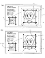
ここで、カッティングエリア枠Cは、サイズ変更および移動ができるようになっている。図5(a)に示すように、カッティングエリア枠Cを拡大あるいは縮小するには、リモートコントローラ3の例えば広域・詳細ボタン33を操作する。この操作がなされた場合、静止画像Vはそのままで、カッティングエリア枠Cのみが、予め設定された複数段階の大きさに拡大(広域ボタンによる操作)あるいは縮小(詳細ボタンによる操作)されて、表示部6に表示される(その縦横比は一定のまま:図3中ステップS6〜S7)。
【0027】
また、図5(b)に示すように、カッティングエリア枠Cを移動するには、リモートコントローラ3の例えばジョイスティック32を操作する。この操作がなされた場合、静止画像Vはそのままで、カッティングエリア枠Cのみが、ジョイスティック32の傾倒された方向に、その大きさを維持したまま移動して表示部6に表示される(図3中ステップS8〜S9)。
【0028】
このようなカッティングエリア枠Cの拡大・縮小や移動等の操作がなされた場合も、拡大・縮小あるいは移動後のカッティングエリア枠Cにおいて、その内側に位置する範囲の画像Aが、表示部6の所定位置、例えば左下にプレビュー画像Pとして表示(描画)される(図3中ステップS5)。これらのプレビュー画像Pも、画像解像度の変更等により所定の大きさで表示部6に表示される。
【0029】
そして、上記カッティングエリア枠Cの拡大・縮小操作や移動操作を必要に応じて繰り返し行い、カッティングエリア枠Cを所望の大きさ・位置に位置決めできた時点で(図3中ステップS10)、決定ボタン35を操作する。すると、この時点でのカッティングエリア枠C内の画像Aに対応した画像データが抜き出され、所定の大きさのシンボルマークを形成するため、画像解像度の変更等の処理も行われる。このようにして、いわば切り取られた画像は、最終的にプレビュー画像Pとして表示されていたものと同じである。
しかる後、切り取られた画像の画像データは、シンボルマークMの画像データ(マーク用データ、シンボルマークのデータ)として記憶部5に記憶される(図3中ステップS11)。
【0030】
上記のようにして、外部から取り込んだ画像から、その一部を切り出し、シンボルマークMとして設定することができるのである。
【0031】
ここで、シンボルマークMとしては、上記したような矩形のものに限らず、例えば図6(a)に示すようなハート型をはじめ丸型、三角形、菱形、多角形等、様々な形状のものとすることが可能である。ハート型のシンボルマークM’を生成するには、図6(a)に示したようなハート型のカッティングエリア枠(編集枠)C’を予め用意しておき、カッティングエリア枠C’の内側の範囲の画像A’のみを切り出してシンボルマークM’とすれば良い。このとき、プレビュー画像P’も、カッティングエリア枠C’に対応した形状となる。
このようなシンボルマークM’を表示部6に表示する場合、実際の画像データ全体としては、図6(b)に示すような略矩形状をなした範囲の画像データ設定であるのが通常である。このため、シンボルマークM’を上記したような異形のものとする場合、画像データとしては矩形状の範囲のデータとし、カッティングエリア枠C’よりも外側の範囲(図中斜線の部分)のピクセル(PIXEL)値を透過色に設定し、下地の画像(電子地図E)を表示するようにする。
【0032】
上記の如くして作成されたシンボルマークMは、通常のシンボルマークと同様、ユーザーの設定により電子地図上の任意の位置に表示できるようになっている。これには、シンボルマークMを表示すべき位置座標データと、記憶部5においてこのシンボルマークMが記憶されているアドレスとが関連付けて記憶部5に記憶されている。さらに、シンボルマークMにユーザーが定義した名称を関連付けて記憶部5に記憶させておくことも可能である。
【0033】
図7は、作成したシンボルマークMを、地図や測位データ等と合成して表示するための構成を示す図である。また図8に示すものは、上記のようにして生成した独自のシンボルマークMを、電子地図E上の任意の位置に登録し、これを電子地図Eとともに表示部6に表示した例である。
このようなナビゲーション装置では、基本的には、演算処理部1に備えられた地図表示回路(地図データ出力手段)21により、従来と同様、図示しないCD−ROM、DVD−ROM等の記憶媒体に格納された電子情報からなる地図データ(他のデータ)を読み出し、リモートコントローラ3のジョイスティック32や広域・詳細ボタン33等で選択された範囲の電子地図Eの地図データを出力する。
また、測位部2での測位結果に基づく自らの現在位置や移動軌跡を形成するための測位データ等を、演算処理部1に備えられた測位データ表示回路(測位データ出力手段)22により出力する。さらに、ユーザーが設定した移動ルートデータ等は記憶部5に格納され、必要に応じ、設定された移動ルートデータ等が、演算処理部1の移動ルートデータ出力回路24により出力される。
そして、電子地図Eの表示部6に表示される範囲内に、その位置座標が含まれるシンボルマークMがある場合には、記憶部5を参照して該当するシンボルマークMの画像データを、演算処理部1に備えられたシンボルマーク表示回路(シンボルマーク表示手段,シンボルマーク出力手段)25により出力する。
これら出力された地図データ、測位データ、移動ルートデータ、シンボルマークMの画像データは、演算処理部1に備えられた合成回路(合成データ出力手段)23において合成され、合成データとして表示部6に出力される。そして図8に示したように、表示部6においては、この合成データに基づく画像、つまり電子地図Eに、シンボルマークMと、測位データ、移動ルートデータ等が合成されて表示される。
このとき、このシンボルマークMにユーザーが定義した名称がある場合には、その名称を表示部6に合成して表示するようにしても良い。そして、ROM8に格納されたルート案内プログラムによって、設定した移動ルートに基づくルート案内を行う。
【0034】
また、例えばナビゲーション用のルート設定画面等においては、ユーザーが登録したシンボルマークMと、これに対応する名称等を一覧表示しても良い。この場合、ユーザーは、一覧表示されたシンボルマークMを選択することにより、出発地、目的地、経由地等の設定を行うこともできる。
ここで、上記したような電子地図EやシンボルマークMの表示方法等については、従来、通常のシンボルマークの場合と同様であり、より具体的には、例えば、本出願人が既に出願した特開平5−307358号公報の技術等を適用できる。
【0035】
上述したナビゲーション装置では、外部から取り込んだ画像からその一部を切り出し、シンボルマークMを生成することができるようになっている。このとき、外部から取り込む画像として、例えば知人の写真、店舗や施設等の外観や看板等の写真を用いることにより、生成したシンボルマークMのそれぞれと、そシンボルマークMが指し示す対象の場所(知人、店舗、施設等)とを、一意的に結びつけることが容易に行える。このようなシンボルマークMを電子地図E上に表示することにより、シンボルマークMの識別が容易かつ確実に行え、ナビゲーション装置の画面認識性を高めるとともに使い勝手を向上させ、商品付加価値を高めることができる。
【0036】
なお、上記実施の形態において、シンボルマーク作成エディタの操作をリモートコントローラ3で行う構成としたが、これはあくまでもその一例に過ぎず、他の方法で操作を行うようにしても良い。
【0037】
また、様々な形のシンボルマークMを生成するため、例えばハート型等のカッティングエリア枠C’を予め用意しておく構成としたが、これに限るものではなく、例えば標準となる矩形のカッティングエリア枠Cを任意の形状に変形可能な構成としておいても良い。このような場合、例えば、ジョイスティック32等でカッティングエリア枠Cの変形操作を行うことは、例えばパーソナルコンピュータの描画用のソフトウェア等と同様の方法を適用すれば実現が可能である。そしてこのようにカッティングエリア枠Cを任意の形状とする場合も、その外側の範囲のピクセル(PIXEL)値を透過色に設定し、下地の画像(電子地図E)を透過させて表示すればよい。
また、生成して登録することのできるシンボルマークMの数(種類)は、予めシンボルマーク作成エディタで設定した範囲内、あるいは記憶部5の記憶容量の範囲内であれば、複数設定可能である。
【0038】
また、ナビゲーション装置全体の構成についても何ら限定する意図はなく、いかなる構成のものであっても良い。
さらに、電子地図情報を表示するのであれば、ナビゲーション装置以外にも本発明を適用することが可能である。
【0039】
また、本発明は、上記実施の形態で示したような処理を行うプログラムを記憶させたCD−ROM、DVD、メモリ、ハードディスク等の記憶媒体の形態とすることも可能である。特に、携帯電話等を介してインターネット等の外部ネットワークに接続可能な機能を有しているナビゲーション装置であれば、上記のようなプログラムを記憶する記憶媒体により当該プログラムを実行すれば、上記実施の形態で示したような構成を実現可能である。
加えて、上記のようなプログラムを記憶するCD−ROM、DVD、メモリ、ハードディスク等の記憶手段と、この記憶手段から当該プログラムを読み出し、当該プログラムを実行する装置側に直接あるいは間接的に当該プログラムを送信する送信手段とを備える伝送装置等の形態を成していても良い。
【0040】
これ以外にも、本発明の主旨を逸脱しない範囲内であれば、上記実施形態の各部の構成を適宜変更しても何ら支障はない。
【0041】
【発明の効果】
以上説明したように、本発明によれば、施設や店舗の外観や看板、知人の顔の写真等、対象となる場所を象徴する画像の画像データを外部から取り込み、その一部を切り出してシンボルマークを生成することにより、ユーザー独自のシンボルマークを作成することができ、電子地図の認識性を高めるとともにその使い勝手を向上させ、商品付加価値を高めることができる。
【図面の簡単な説明】
【図1】 本実施の形態におけるナビゲーション装置の全体的なシステム構成を説明するための図である。
【図2】 前記ナビゲーション装置で用いるリモートコントローラの一例を示す外観図である。
【図3】 同ナビゲーション装置におけるシンボルマーク生成手順を示すフローチャートである。
【図4】 シンボルマークを生成するに際しての表示画面の一例を示す図であり、取り込んだ画像上に編集枠を表示させた状態である。
【図5】 シンボルマークの生成途中の状態の例を示す図であり、(a)は、図4に対し編集枠を縮小した状態、(b)は(a)に対して編集枠を移動させた状態である。
【図6】 他の形のシンボルマークを作成する場合の図である。
【図7】 シンボルマークを電子地図や測位データ等と合成して表示するための構成を示す図である。
【図8】 生成したシンボルマークを、電子地図上の任意の位置に登録し、これを電子地図とともに表示した例である。
【図9】 従来のシンボルマークの例を示す図である。
【符号の説明】
1…演算処理部(画像データ取り込み手段)、3…リモートコントローラ、5…記憶部(シンボルマーク格納手段)、6…表示部(画像表示手段、表示手段)、11…記憶媒体(外部記憶媒体)、12…データ送受信部(画像データ取得手段)、21…地図表示回路(地図データ出力手段)、22…測位データ表示回路(測位データ出力手段)、23…合成回路(合成データ出力手段)、25…シンボルマーク表示回路(シンボルマーク表示手段,シンボルマーク出力手段)、32…ジョイスティック、33…広域・詳細ボタン、35…決定ボタン、C、C’…カッティングエリア枠(編集枠)、E…電子地図、M、M’…シンボルマーク、V…静止画像(画像、取り込んだ画像)[0001]
BACKGROUND OF THE INVENTION
The present invention relates to an electronic map display device that displays electronic map information, a navigation device that uses electronic map information, and a recording medium.
[0002]
[Prior art]
In recent years, map information has been digitized and can be displayed and used on a screen of a personal computer or the like. In a navigation device or the like, digitized map information is used and the current position, travel route, and the like are superimposed on a map and displayed on a monitor.
[0003]
In such electronic map information, for example, landmarks (landmarks) such as government offices, government offices, hospitals, other buildings, companies, stores, etc. are often displayed on the electronic map. Furthermore, on the user side, for example, position information of a specific place such as a store, company, various facilities, acquaintance's house, etc. is registered, and the position can be displayed on an electronic map by a so-called symbol mark or the like. There are also things.
[0004]
For example, in a navigation apparatus, various types of symbol marks such as a dining facility, a tourist facility, and a leisure facility are stored in advance. More specifically, for example, there are baseball symbol mark M1, golf symbol mark M2, tennis symbol mark M3 and the like as symbol marks for leisure (sports) facilities, as shown in FIG.
The user side selects a symbol mark that symbolizes the target location from the list of symbol marks, and registers it at an arbitrary position on the electronic map. The symbol mark registered in this way is displayed on the electronic map on the navigation screen, and the presence, position, and type of the set target can be recognized at a glance, thereby improving the visibility of the navigation device. Yes. These symbol marks can be improved in operability when the user sets a destination, for example.
[0005]
[Problems to be solved by the invention]
However, conventionally, a symbol mark prepared (stored) in advance in an electronic map display device, a navigation device, or the like merely represents a “type” of a target. Therefore, for example, when a golf course is registered with the symbol mark M1, all the registered golf courses are displayed with the same symbol mark M1, and it is difficult to identify the golf course.
For this reason, a plurality of symbol marks may be prepared for one “type”. For example, as shown in FIG. 9, a plurality of symbol marks M4, M5, and M6 are prepared as “human face” symbol marks. This makes it possible to use these symbol marks M4, M5, M6 for “acquaintance's house”, for example, and this may facilitate identification, but in practice the number of marks that can be used is Of course, it is limited, and it is difficult to recognize at a glance which symbol mark (for example, the symbol mark M5) indicates which person.
Thus, in the current situation, it has not always been said that the conventional form of use of symbol marks is good in recognition and usability.
[0006]
The present invention has been made based on such a technical problem, and an object thereof is to provide an electronic map display device, a navigation device, and a recording medium that are easier to recognize and more convenient to use.
[0007]
[Means for Solving the Problems]
For this purpose, the present invention is an electronic map display device for displaying an electronic map based on map data composed of electronic information, the image data capturing means for capturing image data from outside, and the image data capturing means for capturing the image data. An image display means for displaying an image based on the image data, a mark data generation means for generating a mark data by cutting out a part of the image displayed on the image display means, and based on the mark data Symbol mark display means for displaying an image on the electronic map as a symbol mark.
With such a configuration, it is possible to generate a symbol mark by cutting out a part of image data captured from the outside and display it on an electronic map. Thereby, it is possible to create a user-specific symbol mark instead of a symbol mark prepared in advance in the electronic map display device.
Here, the image data captured from the outside is symbolic of the object represented by the symbol mark, for example, a facility or a store, an acquaintance's house, etc. More specifically, a photograph of the appearance or signboard, etc. of the facility or store, an acquaintance It is preferable to use a photo of the face.
[0008]
Further, in this electronic map display device, the external storage medium can be made portable by adopting a configuration for taking in the image data stored in the removable external storage medium. As a result, it is possible to easily handle the image data to be captured. Further, the electronic map display device can be made systematic by configuring the external storage medium as a module so that it can be shared by other devices.
[0009]
Furthermore, if image data is acquired from an external image data source and imported into an electronic map display device, the image data can be acquired from an external network such as the Internet. Image data acquisition means used at this time includes a portable telephone terminal, a portable data communication terminal, a communication modem, and the like.
[0010]
In addition, the navigation device of the present invention includes a symbol mark generation unit that generates a symbol mark from image data captured from outside, a symbol mark storage unit that stores symbol mark data generated by the symbol mark generation unit, and the symbol Symbol mark output means for outputting the data of the symbol mark from mark storage means, map data output means for outputting the map data, positioning data output means for outputting positioning data of the current position, the map data, and the map data The image processing apparatus may include composite data output means for outputting composite data obtained by combining the positioning data and the symbol mark data, and display means for displaying an image based on the composite data. With this configuration, a part of image data captured from the outside is cut out to generate a symbol mark, and this symbol mark can be displayed on the screen (display means) of the navigation device together with the map data and the positioning data. it can.
[0011]
In the symbol mark generation means, the captured image is displayed on the display means, and an edit frame whose size and position can be changed is displayed on the display means so as to overlap the image, and is surrounded by the edit frame. The symbol mark may be generated by extracting image data corresponding to the image in the range.
In this way, the work of extracting the symbol mark from the captured image can be easily performed. In addition, operation means basically provided in the navigation device, for example, a “wide area / detail changeover switch” for changing the display range (scale) of the electronic map, a “scroll button” for scrolling the display range of the electronic map, If operations such as enlargement / reduction and movement of the editing frame are performed using a “joystick” or the like, the above operation can be performed using an existing remote controller or the like.
[0012]
Further, the storage medium of the present invention performs a process of generating a symbol mark by cutting out a part of image data captured from the outside by a stored program and outputting the symbol mark and other data such as map data. It can be carried out. By causing such a program to be executed by a computer such as an electronic map display device or a navigation device, it is possible to perform a composite display of the symbol mark and other data such as map data.
The electronic map display method of the present invention is an electronic map display method for displaying an electronic map based on map data consisting of electronic information, and includes an image data capturing step for capturing image data from the outside, and an image data capturing step. An image display step for displaying an image based on the image data, a mark data generation step for generating a mark data by cutting out a part of the image displayed in the image display step, and an image based on the mark data as a symbol And a symbol mark display step of displaying on the electronic map as a mark.
[0013]
DETAILED DESCRIPTION OF THE INVENTION
Hereinafter, the present invention will be described in detail based on embodiments shown in the accompanying drawings.
FIG. 1 is a diagram for explaining an overall system configuration of a navigation device (electronic map display device) according to the present embodiment. In this figure, reference numeral 1 is an arithmetic processing unit (image data fetching means) that controls the entire navigation device, 2 is a positioning unit that measures its own position, 3 is a remote controller as operation means for the navigation device, and 4 is a remote controller. 3 is a receiving unit for receiving operation information from 3, 5 is a storage unit (symbol mark storage unit) composed of a non-volatile memory such as a hard disk drive or flash memory, and 6 is a display unit (image display unit, display unit) such as a monitor. is there.
[0014]
Here, the arithmetic processing unit 1 includes a
[0015]
The positioning unit 2 performs positioning by GPS (Global Positioning System), and a signal of 1575.42 MHz (normally four or more) GPS satellites with an altitude of about 20,000 km (four or more) Radio wave) is received by a receiving antenna (not shown), positioning calculation is performed based on this signal, and positioning data indicating the current position is transferred to the arithmetic processing unit 1.
[0016]
Various operations of the navigation device are performed by, for example, a
[0017]
Further, as shown in FIG. 1, the navigation device includes a storage medium (external storage medium) 11 and a data transmission / reception unit (image data acquisition means) 12 in order to capture image data and the like from at least the outside. . The
[0018]
Examples of the
By using the removable and
[0019]
Examples of the data transmitting / receiving
[0020]
The data transmitter /
If the data transmission /
[0021]
In this way, the data transmission /
[0022]
In the navigation apparatus configured as described above, a symbol mark creation program (mark data generation means, symbol mark generation means; hereinafter referred to as “symbol mark creation editor”) is stored in the
In order to create a symbol mark with this symbol mark creation editor, first, the operation menu is displayed on the
[0023]
Next, image data of an external still image (image, captured image) V is captured from the
Here, for example, the still image V may be rotated by operating the
[0024]
FIG. 4 is a diagram showing an example of a display screen when generating symbol marks. As shown in this figure, the still image V based on the captured image data is displayed on the display unit 6 (step S3 in FIG. 3). Here, the still image V is, for example, a photograph of a user's acquaintance.
Then, along with the display of the still image V, a cutting area frame (editing frame) C having a substantially rectangular shape is displayed on the still image V of the display unit 6 (step S4 in FIG. 3). The cutting area frame C indicates an outer frame of a range cut out from the still image V displayed on the
[0025]
When the cutting area frame C is displayed on the
[0026]
Here, the cutting area frame C can be resized and moved. As shown in FIG. 5A, in order to enlarge or reduce the cutting area frame C, for example, the wide area / detail button 33 of the
[0027]
Further, as shown in FIG. 5B, in order to move the cutting area frame C, for example, the
[0028]
Even when such an operation such as enlargement / reduction or movement of the cutting area frame C is performed, the image A in the range located inside the cutting area frame C after the enlargement / reduction or movement is displayed on the
[0029]
Then, when the cutting area frame C is enlarged / reduced or moved as necessary, the cutting area frame C can be positioned at a desired size / position (step S10 in FIG. 3), a
Thereafter, the image data of the clipped image is stored in the
[0030]
As described above, a part of an image taken from outside can be cut out and set as the symbol mark M.
[0031]
Here, the symbol mark M is not limited to the rectangular shape as described above, but has various shapes such as a heart shape, a round shape, a triangle shape, a rhombus shape, and a polygon shape as shown in FIG. Is possible. In order to generate the heart-shaped symbol mark M ′, a heart-shaped cutting area frame (editing frame) C ′ as shown in FIG. 6A is prepared in advance, and the inside of the cutting area frame C ′ is prepared. What is necessary is just to cut out only the image A ′ in the range and make it a symbol mark M ′. At this time, the preview image P ′ also has a shape corresponding to the cutting area frame C ′.
When such a symbol mark M ′ is displayed on the
[0032]
The symbol mark M created as described above can be displayed at an arbitrary position on the electronic map according to user settings, as in the case of a normal symbol mark. For this, the position coordinate data for displaying the symbol mark M and the address where the symbol mark M is stored in the
[0033]
FIG. 7 is a diagram showing a configuration for displaying the generated symbol mark M by combining it with a map, positioning data, or the like. FIG. 8 shows an example in which the original symbol mark M generated as described above is registered at an arbitrary position on the electronic map E and displayed on the
In such a navigation apparatus, basically, a map display circuit (map data output means) 21 provided in the arithmetic processing unit 1 is used to store a storage medium such as a CD-ROM or DVD-ROM (not shown) as in the conventional case. The map data (other data) composed of the stored electronic information is read, and the map data of the electronic map E in the range selected by the
Further, positioning data display circuit (positioning data output means) 22 provided in the arithmetic processing unit 1 outputs its own current position and positioning data based on the positioning result in the positioning unit 2. . Further, the travel route data and the like set by the user are stored in the
When the symbol mark M including the position coordinates is within the range displayed on the
The output map data, positioning data, travel route data, and image data of the symbol mark M are synthesized in a synthesis circuit (synthetic data output means) 23 provided in the arithmetic processing unit 1 and are displayed on the
At this time, if there is a name defined by the user in the symbol mark M, the name may be synthesized and displayed on the
[0034]
For example, on the route setting screen for navigation, a symbol mark M registered by the user and a name corresponding to the symbol mark M may be displayed as a list. In this case, the user can also set the starting point, the destination, the waypoint, etc. by selecting the symbol mark M displayed in a list.
Here, the display method of the electronic map E and the symbol mark M as described above is the same as that of a normal symbol mark in the past, and more specifically, for example, a special application already filed by the present applicant. The technique etc. of Kaihei 5-307358 is applicable.
[0035]
In the navigation apparatus described above, a symbol mark M can be generated by cutting out a part of an image captured from the outside. At this time, by using, for example, a photograph of an acquaintance, a photograph of the appearance of a store or a facility, a signboard, etc. as an image captured from outside, each of the generated symbol marks M and a target location (acquaintance) , Stores, facilities, etc.) can be easily linked uniquely. By displaying such a symbol mark M on the electronic map E, the symbol mark M can be easily and reliably identified, improving the screen recognizability of the navigation device, improving the usability, and increasing the added value of the product. it can.
[0036]
In the above embodiment, the operation of the symbol mark creation editor is performed by the
[0037]
Further, in order to generate the symbol mark M of various shapes, for example, a cutting area frame C ′ such as a heart shape is prepared in advance. However, the present invention is not limited to this. For example, a standard rectangular cutting area is used. The frame C may be configured to be deformable into an arbitrary shape. In such a case, for example, performing the deformation operation of the cutting area frame C with the
Further, the number (type) of symbol marks M that can be generated and registered can be set as long as it is within the range set in advance by the symbol mark creation editor or the storage capacity of the
[0038]
Also, there is no intention to limit the configuration of the entire navigation apparatus, and any configuration may be used.
Furthermore, if the electronic map information is displayed, the present invention can be applied to a device other than the navigation device.
[0039]
Further, the present invention may be in the form of a storage medium such as a CD-ROM, a DVD, a memory, or a hard disk that stores a program for performing processing as described in the above embodiment. In particular, if the navigation device has a function that can be connected to an external network such as the Internet via a mobile phone or the like, if the program is executed by a storage medium that stores the program as described above, The configuration as shown in the form can be realized.
In addition, storage means such as a CD-ROM, DVD, memory, and hard disk for storing the program as described above, and the program is read from the storage means and directly or indirectly to the device executing the program. It may be in the form of a transmission device or the like provided with a transmission means for transmitting.
[0040]
In addition to this, there is no problem even if the configuration of each part of the above embodiment is appropriately changed as long as it does not depart from the gist of the present invention.
[0041]
【The invention's effect】
As described above, according to the present invention, image data of an image that symbolizes a target location, such as an exterior or signboard of a facility or a store, a photograph of an acquaintance's face, is taken in from the outside, and a part of the image data is cut out By generating the mark, it is possible to create a user-specific symbol mark, improve the recognizability of the electronic map, improve its usability, and increase the added value of the product.
[Brief description of the drawings]
FIG. 1 is a diagram for explaining an overall system configuration of a navigation device according to an embodiment.
FIG. 2 is an external view showing an example of a remote controller used in the navigation device.
FIG. 3 is a flowchart showing a symbol mark generation procedure in the navigation device.
FIG. 4 is a diagram showing an example of a display screen when generating a symbol mark, in a state where an edit frame is displayed on a captured image.
FIGS. 5A and 5B are diagrams illustrating an example of a state in the process of generating a symbol mark, where FIG. 5A is a state in which the editing frame is reduced with respect to FIG. 4, and FIG. It is in the state.
FIG. 6 is a diagram when a symbol mark of another shape is created.
FIG. 7 is a diagram showing a configuration for combining and displaying a symbol mark with an electronic map, positioning data, and the like.
FIG. 8 is an example in which a generated symbol mark is registered at an arbitrary position on an electronic map and displayed together with the electronic map.
FIG. 9 is a diagram illustrating an example of a conventional symbol mark.
[Explanation of symbols]
DESCRIPTION OF SYMBOLS 1 ... Arithmetic processing part (image data taking means), 3 ... Remote controller, 5 ... Storage part (symbol mark storage means), 6 ... Display part (image display means, display means), 11 ... Storage medium (external storage medium) , 12 ... Data transmission / reception unit (image data acquisition means), 21 ... Map display circuit (map data output means), 22 ... Positioning data display circuit (positioning data output means), 23 ... Synthesis circuit (synthesis data output means), 25 ... Symbol mark display circuit (symbol mark display means, symbol mark output means), 32 ... Joystick, 33 ... Wide area / detail button, 35 ... Decision button, C, C '... Cutting area frame (editing frame), E ... Electronic map , M, M '... symbol mark, V ... still image (image, captured image)
Claims (7)
外部から画像データを取り込む画像データ取り込み手段と、
前記画像データ取り込み手段で取り込んだ前記画像データに基づき画像を表示する画像表示手段と、
前記画像表示手段に表示された前記画像の一部を切り出してマーク用データを生成するマーク用データ生成手段と、
前記マーク用データに基づく画像を、シンボルマークとして前記電子地図上に表示するシンボルマーク表示手段と、
を備えることを特徴とする電子地図表示装置。An electronic map display device that displays an electronic map based on map data comprising electronic information,
Image data capturing means for capturing image data from outside;
Image display means for displaying an image based on the image data captured by the image data capture means;
Mark data generating means for cutting out a part of the image displayed on the image display means and generating mark data;
Symbol mark display means for displaying an image based on the mark data on the electronic map as a symbol mark;
An electronic map display device comprising:
前記画像データ取り込み手段は、前記外部記憶媒体に格納された前記画像データを読み出して取り込むことを特徴とする請求項1記載の電子地図表示装置。The image data is stored in an external storage medium that can be detachably attached to the electronic map display device,
2. The electronic map display device according to claim 1, wherein the image data capturing means reads and captures the image data stored in the external storage medium.
外部から取り込んだ画像データからシンボルマークを生成するシンボルマーク生成手段と、
前記シンボルマーク生成手段で生成したシンボルマークのデータを格納するシンボルマーク格納手段と、
前記シンボルマーク格納手段から前記シンボルマークのデータを出力するシンボルマーク出力手段と、
前記地図データを出力する地図データ出力手段と、
前記現在位置の測位データを出力する測位データ出力手段と、
前記地図データと前記測位データと前記シンボルマークのデータとを合成した合成データを出力する合成データ出力手段と、
前記合成データに基づく画像を表示する表示手段と、
を備えることを特徴とするナビゲーション装置。In a navigation device that displays a current position measured based on signals transmitted from a plurality of GPS satellites and an electronic map based on map data composed of electronic information,
Symbol mark generation means for generating a symbol mark from image data captured from outside;
Symbol mark storage means for storing symbol mark data generated by the symbol mark generation means;
Symbol mark output means for outputting data of the symbol mark from the symbol mark storage means;
Map data output means for outputting the map data;
Positioning data output means for outputting positioning data of the current position;
Combined data output means for outputting combined data obtained by combining the map data, the positioning data, and the data of the symbol mark;
Display means for displaying an image based on the composite data;
A navigation device comprising:
取り込んだ画像を前記表示手段に表示させるとともに、
大きさおよび位置が変更可能な編集枠を、前記表示手段に前記画像に重ねて表示し、
前記編集枠で囲まれた範囲の前記画像に対応した画像データを抜き出して前記シンボルマークを生成することを特徴とする請求項4記載のナビゲーション装置。In the symbol mark generating means,
While displaying the captured image on the display means,
An edit frame whose size and position can be changed is displayed on the display means so as to overlap the image,
5. The navigation apparatus according to claim 4, wherein the symbol mark is generated by extracting image data corresponding to the image in a range surrounded by the edit frame.
前記プログラムは、
外部から画像データを取り込む処理と、
前記画像データに基づく画像からその一部を抜き出しシンボルマークを生成する処理と、
生成した前記シンボルマークのデータを記憶する処理と、
前記シンボルマークのデータと地図データとを呼び出し、これら前記シンボルマークのデータと前記地図データとを合成して出力する処理と、
を前記コンピュータに実行させることを特徴とする記憶媒体。In a storage medium that stores a program to be executed by a computer so that the computer can read the program,
The program is
Processing to import image data from outside,
A process of extracting a part of the image based on the image data and generating a symbol mark;
Processing for storing the generated data of the symbol mark;
Call the data and the map data of the symbol mark, and these said data and said map data and synthesizes the output of symbol processing,
That the computer executes.
外部から画像データを取り込む画像データ取り込みステップと、
前記画像データ取り込みステップで取り込んだ前記画像データに基づき画像を表示する画像表示ステップと、
前記画像表示ステップに表示された前記画像の一部を切り出してマーク用データを生成するマーク用データ生成ステップと、
前記マーク用データに基づく画像を、シンボルマークとして前記電子地図上に表示するシンボルマーク表示ステップと、を備えることを特徴とする電子地図表示方法。An electronic map display method for displaying an electronic map based on map data consisting of electronic information,
An image data capturing step for capturing image data from the outside;
An image display step for displaying an image based on the image data captured in the image data capture step;
A mark data generation step of generating a mark data by cutting out a part of the image displayed in the image display step;
An electronic map display method comprising: a symbol mark display step of displaying an image based on the mark data on the electronic map as a symbol mark.
Priority Applications (1)
| Application Number | Priority Date | Filing Date | Title |
|---|---|---|---|
| JP2000133267A JP4403336B2 (en) | 2000-05-02 | 2000-05-02 | Electronic map display device, navigation device, storage medium, and electronic map display method |
Applications Claiming Priority (1)
| Application Number | Priority Date | Filing Date | Title |
|---|---|---|---|
| JP2000133267A JP4403336B2 (en) | 2000-05-02 | 2000-05-02 | Electronic map display device, navigation device, storage medium, and electronic map display method |
Publications (3)
| Publication Number | Publication Date |
|---|---|
| JP2001317949A JP2001317949A (en) | 2001-11-16 |
| JP2001317949A5 JP2001317949A5 (en) | 2007-03-22 |
| JP4403336B2 true JP4403336B2 (en) | 2010-01-27 |
Family
ID=18641795
Family Applications (1)
| Application Number | Title | Priority Date | Filing Date |
|---|---|---|---|
| JP2000133267A Expired - Fee Related JP4403336B2 (en) | 2000-05-02 | 2000-05-02 | Electronic map display device, navigation device, storage medium, and electronic map display method |
Country Status (1)
| Country | Link |
|---|---|
| JP (1) | JP4403336B2 (en) |
Families Citing this family (6)
| Publication number | Priority date | Publication date | Assignee | Title |
|---|---|---|---|---|
| US8274719B2 (en) | 2001-11-30 | 2012-09-25 | Canon Kabushiki Kaisha | Printing system, print preview method, and preview method using a printer driver |
| JP4043259B2 (en) | 2002-03-14 | 2008-02-06 | 富士通テン株式会社 | Information processing device |
| DE102007042038A1 (en) * | 2007-09-05 | 2009-03-12 | Navigon Gmbh | Navigation device and method for operating a navigation device |
| CN102982038A (en) * | 2011-09-06 | 2013-03-20 | 上海无戒空间信息技术有限公司 | Edit method of map and edit device thereof |
| JP2013253978A (en) * | 2013-06-25 | 2013-12-19 | Kyocera Corp | Mobile telephone |
| CN110427036A (en) * | 2019-08-14 | 2019-11-08 | 成都普诺思博科技有限公司 | A kind of cloud management system of commercialization clean robot |
-
2000
- 2000-05-02 JP JP2000133267A patent/JP4403336B2/en not_active Expired - Fee Related
Also Published As
| Publication number | Publication date |
|---|---|
| JP2001317949A (en) | 2001-11-16 |
Similar Documents
| Publication | Publication Date | Title |
|---|---|---|
| US10564838B2 (en) | Method and apparatus for providing POI information in portable terminal | |
| KR101977703B1 (en) | Method for controlling photographing in terminal and terminal thereof | |
| US9485421B2 (en) | Method and apparatus for operating camera function in portable terminal | |
| CN109146954A (en) | Augmented reality interface for being interacted with shown map | |
| US20110316970A1 (en) | Method for generating and referencing panoramic image and mobile terminal using the same | |
| KR20140133640A (en) | Method and apparatus for providing contents including augmented reality information | |
| WO2013118417A1 (en) | Information processing device, information processing method, and program | |
| US20080273109A1 (en) | Portable device with interactive display and geographical location capability | |
| CA2630944C (en) | User interface for editing photo tags | |
| JP2006059136A (en) | Viewer apparatus and its program | |
| WO2010029671A1 (en) | System capable of displaying virtual information added to visibility information | |
| WO2011004608A1 (en) | System capable of displaying visibility information to which virtual information is added | |
| JP6107518B2 (en) | Information processing apparatus, information processing method, and program | |
| CN109684277B (en) | Image display method and terminal | |
| JP5478242B2 (en) | Map display device, map display method, and program | |
| US8643679B2 (en) | Storage medium storing image conversion program and image conversion apparatus | |
| CN113936699B (en) | Audio processing method, device, equipment and storage medium | |
| JP6514418B2 (en) | Imaging system, imaging method, and program | |
| JP4403336B2 (en) | Electronic map display device, navigation device, storage medium, and electronic map display method | |
| EP4195647A1 (en) | Image processing method, mobile terminal, and storage medium | |
| JP2003216927A (en) | Image display program | |
| JP5513806B2 (en) | Linked display device, linked display method, and program | |
| US10459315B2 (en) | Electronic apparatus for displaying overlay images | |
| JP2006047147A (en) | Information providing system | |
| JP2007166383A (en) | Digital camera, image composing method, and program |
Legal Events
| Date | Code | Title | Description |
|---|---|---|---|
| A521 | Written amendment |
Free format text: JAPANESE INTERMEDIATE CODE: A523 Effective date: 20070206 |
|
| A621 | Written request for application examination |
Free format text: JAPANESE INTERMEDIATE CODE: A621 Effective date: 20070206 |
|
| A977 | Report on retrieval |
Free format text: JAPANESE INTERMEDIATE CODE: A971007 Effective date: 20090430 |
|
| A131 | Notification of reasons for refusal |
Free format text: JAPANESE INTERMEDIATE CODE: A131 Effective date: 20090512 |
|
| A521 | Written amendment |
Free format text: JAPANESE INTERMEDIATE CODE: A523 Effective date: 20090617 |
|
| TRDD | Decision of grant or rejection written | ||
| A01 | Written decision to grant a patent or to grant a registration (utility model) |
Free format text: JAPANESE INTERMEDIATE CODE: A01 Effective date: 20091006 |
|
| A01 | Written decision to grant a patent or to grant a registration (utility model) |
Free format text: JAPANESE INTERMEDIATE CODE: A01 |
|
| A61 | First payment of annual fees (during grant procedure) |
Free format text: JAPANESE INTERMEDIATE CODE: A61 Effective date: 20091019 |
|
| FPAY | Renewal fee payment (event date is renewal date of database) |
Free format text: PAYMENT UNTIL: 20121113 Year of fee payment: 3 |
|
| R151 | Written notification of patent or utility model registration |
Ref document number: 4403336 Country of ref document: JP Free format text: JAPANESE INTERMEDIATE CODE: R151 |
|
| FPAY | Renewal fee payment (event date is renewal date of database) |
Free format text: PAYMENT UNTIL: 20121113 Year of fee payment: 3 |
|
| FPAY | Renewal fee payment (event date is renewal date of database) |
Free format text: PAYMENT UNTIL: 20131113 Year of fee payment: 4 |
|
| R250 | Receipt of annual fees |
Free format text: JAPANESE INTERMEDIATE CODE: R250 |
|
| R250 | Receipt of annual fees |
Free format text: JAPANESE INTERMEDIATE CODE: R250 |
|
| R250 | Receipt of annual fees |
Free format text: JAPANESE INTERMEDIATE CODE: R250 |
|
| R250 | Receipt of annual fees |
Free format text: JAPANESE INTERMEDIATE CODE: R250 |
|
| R250 | Receipt of annual fees |
Free format text: JAPANESE INTERMEDIATE CODE: R250 |
|
| R250 | Receipt of annual fees |
Free format text: JAPANESE INTERMEDIATE CODE: R250 |
|
| R250 | Receipt of annual fees |
Free format text: JAPANESE INTERMEDIATE CODE: R250 |
|
| LAPS | Cancellation because of no payment of annual fees |