JP4401681B2 - Light diffuser and optical member or optical device using the same - Google Patents
Light diffuser and optical member or optical device using the same Download PDFInfo
- Publication number
- JP4401681B2 JP4401681B2 JP2003140891A JP2003140891A JP4401681B2 JP 4401681 B2 JP4401681 B2 JP 4401681B2 JP 2003140891 A JP2003140891 A JP 2003140891A JP 2003140891 A JP2003140891 A JP 2003140891A JP 4401681 B2 JP4401681 B2 JP 4401681B2
- Authority
- JP
- Japan
- Prior art keywords
- light
- particles
- group
- input
- major surface
- Prior art date
- Legal status (The legal status is an assumption and is not a legal conclusion. Google has not performed a legal analysis and makes no representation as to the accuracy of the status listed.)
- Expired - Fee Related
Links
Images


Landscapes
- Optical Elements Other Than Lenses (AREA)
- Led Device Packages (AREA)
- Led Devices (AREA)
- Overhead Projectors And Projection Screens (AREA)
Description
【0001】
【発明の属する技術分野】
本発明は、光入力部から光を入力し、拡散後に光出力部から出力させる光拡散体、及び、同光拡散体を用いた光学部材乃至光学デバイスに関し、光学部材の例としては例えば光拡散板、透過型あるいは反射型のスクリーンなどがあり、光学デバイスの例としては、白色光源として用いられる発光素子がある。
【0002】
【従来の技術】
樹脂マトリックス中に、同樹脂マトリックスと屈折率の異なる多数の粒子を分散させた光拡散体は、下記特許文献1〜2に例示されるように、種々のものが提案され、光拡散板や、透過型あるいは反射型のスクリーンの結像部に用いられている。通常、これらは板状の形状を有し、光拡散板や透過型のスクリーンの結像部などに用いる場合には、一方のメジャー面から光を入力し、他方のメジャー面から光を出力させる形態で使用され、反射型のスクリーンの場合なら、光入力に用いるメジャー面の反対面側に反射体を配し、光入力に用いたメジャー面を光出力にも兼用する形態で使用されている。
【0003】
いずれの使用形態においても、光入力部(一方のメジャー面)から拡散体内に導入された光は、樹脂マトリックス内に分散された粒子の径及び濃度に応じた頻度(確率)で粒子に遭遇し、その度に散乱を受ける。可視光を入出力する光拡散体に使用される粒子の径は、通常、最小0,5μm〜最大数十μmの範囲にあり、可視光の波長に比べて十分大きく、従って、光拡散体内での個々の散乱は、周知のミー散乱理論で近似的に記述できる。
【0004】
同理論で知られているように、個々の散乱の散乱効率及び散乱光の角度分布を左右するファクタとして、「光の波長」、「樹脂マトリックスと粒子の屈折率差」及び「粒子の径」の3つのパラメータがある。そして、実際に採用される粒子の添加濃度、径、光拡散体内の通過光路長(透過型であればほぼ板厚、反射型であれば板厚のほぼ2倍)の条件では、入力から出力までに受ける散乱の回数(多重度)はかなり大きくなる。その結果、光拡散体から出力される出力光は、これら多重散乱を経ることで複雑な態様でその属性が変化する。
【0005】
そこで、従来の光拡散体についてこの点を調べてみると、白色光を入力しても正面方向とその周辺方向への出力光が黄色味を帯びる傾向が強いことが判った。このことは、白色光入力時の正面方向とその周辺方向への出力光の色温度が下がり気味であることを意味している。光拡散体の実際面への応用、例えばプロジェクタから投影された光像を画像として結像部で結像して観察する透過型あるいは反射型のスクリーンを考えた場合、このような色温度の低下傾向は、画像の白色乃至青色部分が鮮やかに映らないという現象をもたらし、商品価値を著しく損なうものである。
【0006】
また、上記した色温度の問題に加えて、従来提案の光拡散体では、出力光(拡散光)の角度拡がりが十分(例えば半値拡がり角度30度以上)なものは、入力光量に対する出力光量の比(全光線透過率;出力側で立体角2πの範囲の積分光量)が低く、全光線透過率が高いものでは、光拡散が不十分で必要な角度拡がりがとれていなかったり、いわゆる「ホットスポット」(入力側の高輝度部がそのまま出力側から透けて観察される現象)が現れたりする場合が多かった。
【0007】
【特許文献1】
特開平1−269901号公報
【特許文献2】
特開2001−66701号公報
【0008】
【発明が解決しようとする課題】
そこで、本発明の基本的な目的は、白色光入力時等の正面方向とその周辺方向への出力光の色温度を高く保つことができ、且つ、全光線透過率の低下を抑えながら出力光に必要な角度拡がりを確保し易い光拡散体を提供することにある。また、本発明は、同光拡散体の特性を生かした光学部材乃至光学デバイスとして、光拡散板、投影された画像を結像させる透過型あるいは反射型のスクリーン、白色光源素子等を併せて提供しようとするものである。
【0009】
【課題を解決するための手段】
本発明は、先ず、光を入力する光入力部と、前記光入力部から入力された光を拡散後に出力させる光出力部を有する光拡散体に適用される。本発明の基本的な特徴に従い、前記光拡散体は、樹脂マトリックス中に、同樹脂マトリックスと異なる屈折率を有する第1群の粒子及び第2群の粒子を分散させた材料で構成される。ここで、第1群及び第2群の粒子は、それぞれ最頻径R1 、R2 (但し、R1 <R2 )を持つ、粒子径分布の拡がりが小さいグループ(最頻径に近い粒子が大多数を占める)を形成している。
【0010】
具体的に言えば、第1群の粒子は、個数粒径分布について第1の最頻径R1 を有するとともに、第1の最頻径R1 に対し±0.5μmの範囲内に70分率以上の個数を含み、第2群の粒子は、個数粒径分布について第1の最頻径R1 より大きい第2の最頻径R2 を有するとともに、第2の最頻径R2 に対し±0.5μmの範囲内に70分率以上の個数を含んでいる。
【0011】
即ち、本発明は、樹脂マトリックスに添加する異屈折率粒子(樹脂マトリックスと屈折率が異なる粒子;以下、同じ)として、各々径を揃えた大小2グループを用意し、そのブレンド添加により、一方のみでは実現できない複数の性質(高色温度、出力光の十分な角度拡がり、高全光線透過率の維持)を同時に実現するものである。詳細は後述するが(基本実施形態参照)、「第1群の粒子を高色温度、高全光線透過率の維持を損なわない範囲内で添加する一方、第2群の粒子を適量添加し、出力光の角度拡がりを補強する」というのが本発明の基本的な考え方である。具体的なブレンドの条件は下記の通りである。なお、下記諸条件1〜条件5の内、条件2及び条件3は樹脂マトリックス中に第1群の粒子を単独で分散させたと仮定した場合の条件として規定し、条件5は、樹脂マトリックス中に第2群の粒子を単独で分散させたと仮定した場合の条件として規定した。
【0012】
[条件1]
第1群の粒子は、下記の式(1)を満たす粒子であること。
0.75≦Qsca (B)/Qsca (R)≦1.25 ・・・(1)
ここで、Qsca (B)は、樹脂マトリックス中において第1群の粒子が起こす1回の散乱について、青色代表波長435nmにおける散乱効率を表わし、Qsca (R)は、同じく樹脂マトリックス中において第1群の粒子が起こす1回の散乱について、赤色代表波長615nmにおける散乱効率を表わす。散乱効率は、光の波長λ、粒子径r1 、粒子の屈折率n1 、樹脂マトリックスの屈折率nm を与えれば周知のミー散乱理論により近似的に計算される。
【0013】
なお、散乱効率計算時には、径r1 を最頻径R1 で代表させることができる。この条件の意味は、第1群の粒子に、「青色(短波長)〜赤色(長波長)の可視光について、散乱効率の波長依存性が小さい」という性質を要求することにある。
【0014】
また、言うまでもなく、この条件は、第1群の粒子の添加濃度には無関係であり、第1粒子の径、第1粒子の径及び樹脂マトリックスの屈折率の三者の関係を束縛する。
【0015】
[条件2]
下記の式(2)を満たすこと。
T1 (B)≧T1 (R) ・・・(2)
ここで、T1 (B)は、光入力部から青色代表波長435nmの光を入力した場合の光出力部における全光線透過率を表わし、T1 (R)は、光入力部から赤色代表波長615nmの光を入力した場合の光出力部における全光線透過率を表わす。
【0016】
この条件の意味は、第1群の粒子に、「全体として、青色光(短波長可視光)は、赤色光(長波長可視光)と同等かそれ以上に通し易い」という条件での添加を要求することにある。即ち、この条件は、第1粒子のQsca (B)/Qsca (R)と添加濃度に関係し、後述するように、添加濃度が高すぎると満たされなくなる可能性がある。
【0017】
この条件を、透過型スクリーンの結像部に用いるケースに適用すれば、照明光あるいは投影画像光が、入力側のメジャー面から全厚みを拡散されながら通過して出力側のメジャー面から出力された時、出射光全体(立体角2πの全範囲)で、赤成分が青成分よりも出力され易いようになる濃度の添加は禁止されることになる。
【0018】
また、反射型スクリーンの結像部に用いるケースでは、投影画像光が、入力側のメジャー面から全厚みを拡散されながら通過して他方のメジャー面側で反射され、入力側のメジャー面に戻って出力された時、出射光全体(立体角2πの全範囲)で、赤成分が青成分よりも出力され易いようになる濃度の添加は禁止される。
【0019】
[条件3]
下記(3)式
I(x)=I(0)/2 ・・・(3)
を満たすxについて、
下記式(4)
x≧15゜ ・・・(4)が成立すること。
【0020】
ここで、I(θ)は、白色光を光入力部から入力した場合に光出力部から出力される出力光の拡がり角度θ(0゜〜90゜)における光強度を表わす一般表式であり、I(0)はθ=0゜における光強度であり、xは白色光についての半値拡がり角度を表わす。
【0021】
この条件の意味は、第1粒子の添加濃度について、「単独添加で、白色光について、最低15゜の半値拡がり角度を確保する」ことにある。即ち、本発明では、先ず、第1群の粒子で、光拡散による角度拡がり機能の基礎部分として、最低15゜の半値拡がり角度(対白色光)を確保する。
【0022】
[条件4]
下記式(5)
T1 (c1 )≧0.8 ・・・(5)
ここで、T1 (c1 )は、第1粒子の重量濃度c1 (単独添加時)において、光入力部から白色光を入力した場合の光出力部における全光線透過率を表わす。
【0023】
この条件の意味は、第1群の粒子の添加濃度について、「第1粒子の重量濃度c1 を上げすぎて全光線透過率が大きく下がることがないようにする」ことにある。即ち、本発明では、第1群の粒子で光拡散による角度拡がり機能の基礎部分として、最低15゜の半値拡がり角度(対白色光)を確保しつつも(上記第4の条件)、第1群の粒子の添加濃度を抑制し、全光線透過率の低下を回避する。この条件4は、本発明が2種粒子のブレンドを採用する理由に関係している。
【0024】
即ち、第1群の粒子は光拡散能力に優れ、比較的低濃度で上記条件3(半値角度拡がり15゜以上)を満たせるが、そのことは同時に、濃度を上げていくと後方散乱が早めに起こり易いことを意味している(実例については後述する)。従って、第1群の粒子のみで、十分な角度拡がり(例えば半値角度拡がり30゜)を確保しようとすると、全光線透過率が低くなってしまう。つまり、十分な出力拡散光の半値角度拡がりの確保と、高い全光線透過率が確保は、互いにトレードオフの関係にあり、同時に実現することは困難である。本発明は、この困難を第2群の粒子とのブレンド添加で解決する。
【0025】
即ち、上記の「白色光について15゜の半値拡がり角度」は、実際の応用においては狭すぎる視野角条件に該当し、また、半値拡がり角度を更に大きくするために添加濃度を増大させると、散乱の多重度が高まり、後方散乱される光量が増え、全光線透過率が低下する。この制約と、上記条件2の制約から、実際に添加し得る第1群の粒子の濃度には限りがあり、単独添加で「明るく出力光の角度拡がりが十分で色温度も高い」光拡散体を得るのは困難と考えられる。そこで、本発明では、第1群の粒子の添加濃度は上記したような条件2〜4で抑え、第2群の粒子の添加により性能のかさ上げを達成する。
【0026】
第2群の粒子に関する条件5及び条件6は、次の通りである。
【0027】
[条件5]
第2群の粒子は、下記式(6)式を満たす粒子であること。
T2 (3c1 )≧0.8 ・・・(6)
ここで、T2 (3c1 )は、第2群の粒子の重量濃度を、第1群の粒子の重量濃度c1 (実際に添加する重量濃度)の3倍として単独添加した時、光入力部から白色光を入力した場合の光出力部における全光線透過率を表わす。
【0028】
この条件の意味は、第2群の粒子に、「第1群の粒子に比して前方散乱性が十分強く、全光線透過率の濃度依存性が小さい」という性質を要求することにある。つまり、本発明では、第2群の粒子として前方散乱性が十分強い粒子を選択することで、後方散乱光の生成を抑制して全光線透過率の低下を回避しつつ、出力光の角度拡がりの補強調整を行えるようにしている。
【0029】
なお、言うまでもなく、上記(6)式の条件は、第2粒子の実際の添加濃度を規制する条件ではなく、あくまでも樹脂マトリックス中における第2粒子の前方散乱性の強さを表現するものである。
【0030】
[条件6]
下記式(7)、(8)を満たすこと。
c2 ≧0.1(wt%) ・・・(7)
T2 (c2 )≧0.8 ・・・(8)
ここで、c2 は樹脂マトリックスに対して添加される重量濃度(wt%)であり、T(c2 )は同重量濃度の条件で光入力部から白色光を入力した場合の光出力部における全光線透過率を表わす。この条件の意味は、「全光線透過率の目立った低下を起こさない添加濃度範囲で、前方散乱性が十分強く、全光線透過率の濃度依存性が小さい第2群の粒子(条件5参照)を添加して、出力光の角度拡がりの補強調整を必ず行なう」ということにある。
【0031】
このように、本発明は、樹脂マトリックスに対して、上記条件を満たす2種の異屈折率粒子のブレンド添加を行なうことにより、白色光入力時の正面方向とその周辺方向への出力光の色温度を高く保つことができ、且つ、全光線透過率の低下を抑えながら出力光に必要な角度拡がりを確保し得る光拡散体を提供するものである。
【0032】
本発明において、樹脂マトリックスに採用可能な代表的な材料の1つとして、ポリメチルメタクリレート(PMMA)がある。そして、樹脂マトリックスがポリメチルメタクリレートである場合に、第1群及び第2群の粒子として透光性のシリコーン樹脂粒子(ポリメチルシルセスオキサン粒子;以下、同じ)を用いることができる。後述するように、例えば最頻径R1 =約7.3μmのものを第1群の粒子として用意し、最頻径R2 =約9μmのものを第2群の粒子として用意して、PMMA中に分散させることで本発明の特徴を有する光拡散体が得られる。
【0033】
但し、一般には、樹脂マトリックスとそれに組み合わせて用いられる第1群及び第2群の粒子の材料は、これに限定されるものではなく、上述した諸条件を満たす限り一般に任意のものを選択して構わない。
【0034】
次に、上述した光拡散体は、板状の光学部材として用いることができる。即ち、上述した光拡散体を板状体に構成し、その一方のメジャー面を光入力部として用い、他方のメジャー面を光出力部として用いることができる。このような板状の光拡散体は、いわゆる「光拡散板」として、例えば照明光源のカバー、表示・広告灯のカバー等に用いることができる。
【0035】
また、周知の画像プロジェクタからの画像光を入力光として、光拡散体内で画像を形成し、透過型あるいは反射型のスクリーンとして用いることも可能である。言うまでもなく、反射型のスクリーンの結像部に用いる場合には、背面側に反射体が配置される。その場合、上記条件2〜条件5は、反射体が可視光を100%反射する鏡面を持つとして課せられるものとする。
【0036】
更に、周知のように、透過型あるいは反射型のスクリーンにおいては、外乱光(周囲からスクリーンに入射する画像光以外の光で、迷光とも言う;以下、同様)により画像が白っぽくなり、コントラストが低下することを防止するために、画像結像部に外乱光を吸収する光吸収材(例えばカーボンブラック)を添加することが一般的に行なわれており、本発明においても、この手法を適用することができる。その場合には、光吸収材の添加がなかったと仮定した場合に上記諸条件を満たす光拡散体に、光吸収材を添加したものがスクリーンの結像部に用いられる。言うまでもなく、光吸収材を添加すれば、結像部を構成する「光吸収材入りの光拡散体」の全光線透過率は低下するが、それでも、添加前の光拡散体が明るく色温度が高いので、優れた特性のスクリーンが得られる。
【0037】
なお、実施形態で後述するように、光拡散板あるいは透過型/反射型のスクリーンの結像部は、接着層の形態で構成されていても良い。また、透過型/反射型のスクリーンの結像部の前面あるいは背面側にフレネルレンズ、プリズムシート、反射防止膜等が設けられることもあり、結像部の表面をマット面とすることもある。
【0038】
本発明の光学デバイスへの適用としては、発光ダイオード(LED)を発光源として3原色の光を放出する発光部を覆うキャップ部に上述した光拡散体を用いた発光素子がある。この発光素子は、3原色の光を光拡散体で拡散し、明るく鮮やかな白色光として外部に出射する。なお、このような発光素子における「光入力部」は、「発光部からの光が入射する光拡散体の界面」であり、「光出力部」は「拡散光が出射する光拡散体の界面」である。また、全光線透過率や角度拡がりに関連する諸条件は、「発光部から光軸に沿って測った光拡散体の厚さ」と同じ厚さを持つ同材料の「光拡散板」を仮定して定めるものとする。
【0039】
なお、「全光線透過率」の下限については、第1粒子あるいは第2粒子の単独添加における条件とは別に、第1粒子と第2粒子のブレンド添加後の値についても、実用上の観点から例えば80%あるいは85%を下限として課すことも考えられる。この程度の全光線透過率は、後述する具体例で示すように、本発明では容易に達成できる値である。
【0040】
【発明の実施の形態】
[基本実施形態]
先ず、本発明の基本形態に相当する光拡散体とその特性について、図1〜図7を参照して説明する。なお、以下の説明においては、便宜上、「第1群の粒子」、「第2群の粒子」を各々「第1粒子」、「第2粒子」と適宜略称する。
【0041】
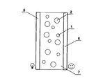
図1(a)は、光拡散体を板状の形状とした本発明の基本形態を説明する図であり、同図に示したように、全体を符号30で表わした板状の光拡散体は、樹脂マトリックス20中に、第1粒子1と、第2粒子2を各々ほぼ均等に分散させたもので、具体的な材料としては、樹脂マトリックス20にはポリメチルメタクリレート(以下、「PMMA」と言う)が用いられ、第1粒子1及び第2粒子2には、透光性のシリコーン樹脂粒子が採用されている。
【0042】
第1粒子1は、最頻径R1 =約7.3μmとして、R1 ±0.5μmの範囲に少なくとも70%の個数が収まるような粒子径の揃い方をしている粒子群を代表する粒子である。これに対して、第2粒子2は、最頻径R2 =約9μm(R1 <R2 )として、R2 ±0.5μmの範囲に少なくとも70%の個数が収まるような粒子径の揃い方をしている粒子群を代表する粒子である。
【0043】
図2は、公称粒径2μm、7.3μm、9μmの3種類の各シリコーン樹脂粒子製品について、粒径分布を測定した結果を示しており、公称粒径7.3μm、9μmの各シリコーン樹脂粒子製品は、第1粒子1及び第2粒子2として粒径の揃い方の条件を満足している。なお、同図のグラフの横軸は粒径(μm)を表わし、縦軸は個数の相対頻度(数字の値自身には特に意味はない)を表わしている。また、粒径分布は、各シリコーン樹脂粒子製品を適量単独添加した光拡散体(サンプル)を作成し、その断面をSEM(走査型電子顕微鏡)で撮影し、画像処理により求めた。図中「モード径」とあるのは、「最頻径」と同意味である。
【0044】
図1(b)には、このような粒子1、2がPMMAマトリックス20中で起こす散乱(1回の散乱)の様子の概略的な特徴を示した。同図において、実線41、51は各々赤色光の第1粒子1及び第2粒子2による散乱後の角度分布を表わし、破線42、52は各々青色光の第1粒子1及び第2粒子2による散乱後の角度分布を表わしている。
【0045】
ミー散乱の理論で知られているように、個々の散乱の態様は、光の波長、各粒子の径、マトリックスとの屈折率の相違に依存して変化する。PMMAマトリックス20中にシリコーン樹脂粒子が存在する場合、可視光について、8μm付近に散乱光の角度拡がり(散乱光強度の角度依存特性)が大きく変わる点があるため、第2粒子2は第1粒子1に比べてはるかに強い前方散乱性を示している。換言すれば、伝播方向の角度分布を広げる作用は、第1粒子1は強く、第2粒子2は弱いということである。
【0046】
また、更に詳細に見ると、短波長である程、「波長に対する相対的な粒径」は大きくなる効果により、1回の散乱では、青色光の方が赤色光よりも前方へ向かう性質が強い。図1(b)における破線図形42、52が実線図形41、51より前方に若干突き出ているはそのことを表わしている。
【0047】
散乱効率については、図1(b)において、赤色光の散乱効率は実践図形41、51の面積で概念的に表現され、青色光の散乱効率は破線図形42、52の面積で概念的に表現されている。図示されているように、先ず赤色光、青色光のいずれに関しても、第1粒子1の方が第2粒子2より散乱効率は高い。また、第1粒子1では、赤色光と青色光で大きな散乱効率の差異はない。換言すれば、第1粒子1の散乱効率の波長依存性が小さい。第2粒子2については、後述するように、赤色光と青色光でかなりの散乱効率の差異がある。
【0048】
以上が、基本形態に係る光拡散体30で用いれらている第1粒子1と第2粒子2による樹脂マトリックス20中での散乱の基本的な特徴の概略である。以下、これを前提に、第1粒子と第2粒子について課された前述の諸条件について、順にその意義を、各条件に関連する特性データ、計測結果等を引用して説明する。なお、各式における変数、記号等の定義の繰り返し記載は省く。
【0049】
(条件1の関連説明);
前述したように、条件1は第1粒子について前出の(1)式を満たすことを要求している。
0.75≦Qsca (B)/Qsca (R)≦1.25 ・・・(1)
既述の通り、この条件の意味は、第1粒子に、「青色(短波長)〜赤色(長波長)の可視光について、散乱効率の波長依存性が小さい」ということである。
【0050】
そこで、PMMA−シリコーン樹脂粒子系について、青色代表光と赤色代表光との散乱効率の比、Qsca (B)/Qsca (R)が粒径の変化に応じてどのように変化するかをミー散乱理論に基づいて計算した結果を図3に示す。同図において、横軸は粒径(μm)を表わし、縦軸は青色代表光(435nm)と赤色代表光(615nm)との散乱効率の比、Qsca (B)/Qsca (R)を表わしている。
【0051】
このグラフから判るように、粒径約5.3μm〜約8.1μm及び約11.5μm〜約13.1μmの領域で、上記(1)式の条件は満たされる。本実施形態(基本形態)で採用されている第1粒子1の粒径(約7.3μm)はこの範囲にあり、従って第1粒子1は上記条件1を満たしている。言い換えれば、第1粒子1は、可視光を比較的均等な効率で散乱する粒子であり、短波長あるいは長波長の可視光に偏った効率で散乱する性質を持つ。
【0052】
なお、第2粒子2の粒径(約9μm)で、青色光の散乱効率が赤色光の散乱効率をかなり下回っている。このことから、一見すると、第2粒子2を添加することは、青色成分を殺すように思われる。しかし、スクリーン等への適用を考えると実際はむしろ有利に作用する。何故ならば、青色光の散乱効率が低いことは、第2粒子2を添加して出力光の角度拡がりを補強した場合、青色成分の方が赤色成分よりも角度拡がりの効果が小さくなる要因であり、正面周辺の方向から見た時、「白さ」の視覚感(鮮やかさ)を改善するように作用するからである。このことは、第2粒子に関する条件4、5との関わっており、詳細は後述する。
【0053】
(条件2の関連説明);
前述したように、条件2は第1粒子を前出の(2)式を満たすように添加することを要求している。
T1 (B)≧T1 (R) ・・・(2)
既述の通り、これは、第1群の粒子に、「全体として、青色光(短波長可視光)は、赤色光(長波長可視光)と同等かそれ以上に通し易い」という条件での添加を意味し、添加濃度が高すぎると満たされなくなる可能性がある。逆に言えば、そのようなケース以外では、一般にこの条件は満たされる。具体的には、次のように推察される。
【0054】
第1粒子による光吸収損失を無視すれば(例えば、ここで採用しているシリコーン樹脂粒子は、極端な高濃度でない限り、光吸収損失は無視できる程小さい)、全光線透過率は、1(100%)から後方散乱率を差し引いたものである。
【0055】
従って、第1粒子のQsca (B)/Qsca (R)が1より小さければ、添加濃度を増す程、多重散乱の効果による後方散乱の増大は赤色成分の方が顕著となり、上記(2)式は満たされ易くなると考えられる。PMMMA−シリコーン樹脂系の場合、前出の図3のグラフから、条件1を満たす前提では、粒径約7μm〜約8.1μmであればこのケースに当てはまる。
【0056】
一方、第1粒子のQsca (B)/Qsca (R)が1より大きい場合には、上記(2)式は添加濃度に関係なく満たされ難いように一見思わる。しかし、実際には、Qsca (B)/Qsca (R)>1でも、添加濃度が比較的低い場合には、上記(2)式は満たされ得る。その理由は、添加濃度が比較的低い場合には、散乱の多重度が低いため、散乱効率の波長依存性よりも散乱角度プロファイル(散乱光の散乱強度の角度特性)の波長依存性が後方散乱の多寡を大きく左右する故であると考えることができる。つまり、青色光の散乱効率が赤色光の散乱効率を上回っていても、個々の散乱において前方散乱性が赤色光よりも青色光で十分強く発揮されれば、散乱の多重度が小さい限り、後方散乱光は赤色光よりも発生し難くなる。
【0057】
ところで、この「個々の散乱において前方散乱性が青色光で強く発揮される」という前提は、現実に成立し得る条件であり、例えばPMMMA−シリコーン樹脂系で成立する。このことは、樹脂マトリックスと第1粒子の屈折率分散(波長依存性)に関係している。図4は、PMMAとシリコーン樹脂の屈折率分散を示したグラフで、横軸は波長(nm)、縦軸は屈折率(左側)及び屈折率差(右側)をを表わしている。
【0058】
3本のカーブは、上から順に、「PMMAマトリックスの屈折率」、「屈折率差(シリコーン樹脂粒子の屈折率−PMMAマトリックスの屈折率:符号がマイナスであることに注意)」、「シリコーン樹脂粒子の屈折率」を表わしている−このグラフから判るように、PMMAとシリコーン樹脂の屈折率差Δn(絶対値)は、青色光で小さく、赤色光で大きい。そのため、ミー散乱理論で知られているように、前方散乱性は赤色光よりも青色光で強く現れる。前出の図1(b)において、第1、第2粒子の双方で、破線図形42、52の方が実線図形41、51よりも尖っているのは、この事実に対応している。
【0059】
上記したことから、PMMMA−シリコーン樹脂系の場合、条件1を満たす前提で、粒径約5.3μm〜約7.3μmのケースでも、添加濃度が低ければ、上記(2)式が満たされ得ることが理解される。逆に言えば、上記(2)式は、拡散光の角度拡がりを確保するために添加される第1粒子の濃度を制限し得るものであり、本発明が青色成分を大切にして、出力光(拡散後に出力される光)に「鮮やかな白さ」を持たせようとしていることの1つの現れである。
【0060】
(条件3の関連説明);
前述したように、条件3は第1粒子について、前出の(3)式を満たすx(半値角度拡がり)が、前出の(4)式を満たすことを要求している。
I1 (x)=I1 (0)/2 ・・・(3)
x≧15゜ ・・・(4)
既述の通り、この条件の意味は、第1粒子の添加濃度について、「単独添加で、白色光について、最低15゜の半値拡がり角度を確保する」ことにある。この条件は、第1粒子の添加濃度の下限を左右する。但し、光入力部から光出力部に至る距離(光拡散板、透過型スクリーンでは厚さにほぼ対応;反射型スクリーンでは、ほぼ厚さの2倍に対応)によって、その下限は変化する。図5は、PMMAに、2.0μm、7.3μm、9.0μmの各シリコーン樹脂粒子(前出の図2のグラフに粒径分布を示した製品)を分散した2mm厚の板について、白色光の半値角度拡がりの値を実測したものである。
【0061】
このグラフから、図1(a)に示した光拡散体30の厚さを2mmとした時、x=15゜を与えるに必要最低限の第1粒子(粒径7.3μm)の添加濃度は、約0.8wt%であることが判る。また、このグラフから、粒径2.0μm、7.3μm、9.0μmの順に粒子径が大きくなる程、同じ半値角度拡がりを得るために必要な濃度が大きくなることが理解される。
【0062】
(条件4の関連説明);
前述したように、条件4は第1粒子について、前出の(5)式を満たすことを要求している。
T1 (c1 )≧0.8 ・・・(5)
既述の通り、この条件の意味は、第1群の粒子の添加濃度について、「第1粒子の重量濃度c1 を上げすぎて全光線透過率が大きく下がることがないようにする」ことにある。図6は、PMMAに、2.0μm、7.3μm、9.0μmの各シリコーン樹脂粒子(前出の図2のグラフに粒径分布を示した製品)を分散した2mm厚の板について、白色光の全光線透過率を実測した結果を示すグラフである。同グラフにおいて、横軸はPMMAマトリックスへの添加濃度をwt%で表わし、縦軸は、白色光の全光線透過率を表わしている。
【0063】
この同グラフから判るように、第1粒子(粒径7.3μm)の場合、添加濃度3wt%と4wt%の付近で全光線透過率が急低下し、全光線透過率0.8を割り込んでいる。このことは、出力拡散光の角度拡がりを大きくするために第1粒子の添加濃度を大きくすると、全光線透過率が低下する危険性が高まることを意味する(前述したトレードオフの関係)。
【0064】
本発明では、条件4で全光線透過率が0.8未満となるような高濃度の第1粒子の添加は禁止される。但し、全光線透過率0.8以上となる上限濃度は、当然、板厚(一般には、光入力部から光出力部までの光路距離)に応じて変化する。一般に、板厚(光路距離)が大きくなれば上限濃度は下がり、板厚(光路距離)が小さくなれば上限濃度は上がる。
【0065】
(条件5の関連説明);
前述したように、第2粒子は、下記式(6)式を満たすような粒子である。
T2 (3c1 )≧0.8 ・・・(6)
つまり、第2粒子は、第1の粒子の重量濃度c1 (実際に添加する重量濃度)の3倍の濃度で仮に単独添加した場合でも、光入力部から白色光を入力した場合の光出力部における全光線透過率が0.8を回らないということである。換言すれば、第2粒子は、第1粒子に比して前方散乱性が十分強く、全光線透過率の濃度依存性が小さいということである。
【0066】
図6のグラフから容易に判るように、本基本実施形態における第2粒子(粒径9μmのシリコーン樹脂粒子)は、板厚2mmの場合、10wt%以上でも80%をはるかに越える全光線透過率を示している。そして、前述の条件4から、第1粒子の添加濃度c1 の上限は、同じ板厚2mmで、3.5wt%程度であるから、本基本実施形態における第2粒子は、本条件5を満足している。なお、既述の通り、この条件は「第2粒子の実際の添加濃度c2 」を規制する条件ではない。「第2粒子の実際の添加濃度c2 」を規制する条件は、次に説明する条件6である。
【0067】
(条件6の関連説明);
既述の通り、第2粒子の実際の添加濃度c2 は、下記式(7)、(8)を満たすように規制される。
c2 ≧0.1(wt%) ・・・(7)
T2 (c2 )≧0.8 ・・・(8)
ここで、式(7)は、「少なくとも一定濃度の第2粒子を必ずブレンドする」ことを意味し、式(8)は、余りに過大な添加濃度は排除するということである。図6のグラフで示したように、前方散乱性が強い第2粒子はかなり高濃度で添加しても高い全光線透過率を維持するが、それにも当然限界はある。そのような過大な添加濃度は、この式(8)の条件で排除される。
【0068】
(ブレンドによる作用の説明);
第1粒子(7.3μmのシリコーン樹脂粒子)、第2粒子(9μmのシリコーン樹脂粒子)のブレンドによる作用を確認するために、図1(a)に示した光拡散体(板厚2mm;基本実施例サンプル)を第1粒子の添加濃度を2wt%、第2粒子の添加濃度を3wt%として作成し、白色光を面31から入力し、面32からの出力光の色温度の角度分布を実測した。また、比較のために、基本実施例サンプルと同形、同寸、同マトリックスで、第1粒子を添加濃度2wt%で単独添加した第1比較サンプルと、第2粒子を添加濃度3wt%で単独添加した第2比較サンプルについて、同じ色温度測定を行なった。面32からの出力光の色温度の角度分布を実測した。これらの結果を図7のグラフに示した。同グラフにおいて、横軸は出力面(面32に対応)の正面方向からのずれ角度を表わし、縦軸は色温度を表わす。このグラフから次のことが読み取れる。
【0069】
(i)第1粒子を添加濃度2wt%で単独添加した第1比較サンプルでは、正面方向周辺の色温度が低く、正面方向からはずれる程、色温度が高くなっている。このような特性は、一般に余り好ましくない。例えば画像投影用のスクリーンの結像部に適用した場合、正面方向から見た画像が黄味あるいは赤味を帯び、白色が鮮やかに見えない。
【0070】
(ii)第2粒子を添加濃度3wt%で単独添加した第2比較サンプルでは、正面方向周辺の色温度は高く、45゜付近から色温度が急落している。この特性から見る限り、画像投影用のスクリーンの結像部に適しているようにも思われる。しかし、第2粒子の単独添加では、図5のグラフで示したように、出力光の角度拡がりを確保する能力が弱く、粒子材料の消費量が増えてしまう。
【0071】
更に、実際上直面する深刻な問題として、第2粒子のように前方散乱性の強い粒子の単独添加を行なった場合、相当の高濃度まで、入力光がそのまま光拡散体を突き抜けて見える現象が発生し、入力光の光源(例えばプロジェクタの投光部)がいわゆる「ホットスポット」として観察される可能性が高まる。また、ホットスポットの出現まで至らなくとも、出力光(スクリーンの場合は画像)にぎらつき感が生じる。
【0072】
(iii)第1粒子を2wt%、第2粒子を3wt%ブレンド添加した基本実施例サンプルでは、正面方向から75゜付近までの広い角度範囲でほぼ一定(8000゜K以上)の色温度が維持されている。そして、この「8000゜K以上」という値は、鮮やかな白を表現する値である。角度拡がりについては、測定値を示していないが、図5のグラフから、27゜の半値角度に、第2粒子の添加による上乗せが行なわれ、30゜以上の半値角度が得られている。結局、基本実施例サンプルは、正面方向から75゜付近までの広い角度範囲から見て色特性が優れ、角度拡がりも十分確保された光拡散体であると言うことができる。また、ホットスポットやぎらつき感の問題も生じない。なお、本発明の実施例における半値角度の実測例については後述する。
【0073】
以上説明した本発明の基本実施形態に係る光拡散体30(図1(a))は、照明装置や表示灯等で用いる光拡散板などに用いることができるが、上述したように、色温度の特性に優れているため、カラーのTV画像、DVD画像等をプロジェクタで投影して観察する各種スクリーン(結像部)への適用性が高い。図8〜図17は、画像投影用のスクリーン(結像部)への適用例(例1〜例8)を列挙したものである。
【0074】
なお、これら図8〜図16及び図17において、光入力部(画像光入力部)はランプマーク(図8で符号Aを例示)を付した側の面であり、光出力部(画像光出力部;観察側の面)は顔マーク(図8で符号Bを例示)を付した側の面である。また、これらの例は、画像投影用のスクリーンとして説明されるが、入力光を画像投影光として、諸用途の光拡散板乃至光拡散器として使用できることは言うまでもない。
【0075】
(例1/例2)
図8は、本発明を透過型スクリーンに適用した第1の例を示し、上述した基本形態の板状の光拡散体を透過型スクリーンの結像部に用いている。即ち、周知のプロジェクタ(図示は省略;例えばカラーTV画像、DVD画像を投影するプロジェクタで、スクリーンの結像部内に画像を結像させるように調整されている;以下、同じ)から投影されたカラー画像光は、この板状の光拡散体内で結像し、その像が拡散光画像として正面方向及び斜め方向から観察される。
【0076】
ここで、上述した光拡散体の優れた特性により、明るく、また、色温度の高い白色(青色成分が豊かで鮮やかな白色)を持つカラー画像が観察される。そして、斜め方向から観察についても、かなりの広角度(正面方向から左右上下30゜以上)にわたって明るさがあまり落ちず、色温度も高いという長所が得られる。但し、周囲が明るい環境で使用した場合、外乱光(画像光以外の光)が拡散され、背景光として画像にかぶってしまうので、画像のコントラストが低下し、例えば画像の黒色が白っぽく見えてしまう。
【0077】
このような現象は、光拡散体をスクリーンに適用した場合に必ず起る問題で、これを回避するには、多少明るさは犠牲にするが、有機色素、カーボンブラック等からなる光吸収剤を光拡散体に添加すれば良い。その例(例2)を図9に示した。図9において、光拡散体に添加された光吸収剤は符号3で示されている。光吸収剤3に用いれられる材料は多種知られており、有機色素、カーボンブラック等がある。また、光吸収剤3の添加濃度は、必要に応じて加減すれば良く、特に制限はないが、明るさの低下を抑えるためには、最小限にとどめることが好ましい。なお、光吸収剤として波長選択性のあるもの(例えば有彩色の有機色素)を用いた場合には、それによる色合いの調整(例えば、赤色成分を更に抑える)も可能である。
【0078】
(例3/例4)
図10、図11は、各々本発明を透過型スクリーンに適用した第3及び第4の例を示している。これら例は、上記した第1の例の変形形態に相当する。即ち、第3の例(図10)で透過型スクリーンの結像部に用いているのは、上述の基本形態で説明した光拡散体の光入力部(画像光入力側の面)をマット処理面4としたものであり、第4の例(図11)で透過型スクリーンの結像部に用いているのは、同じく基本形態で説明した光拡散体の光入力部(画像光入力側の面)にマット処理を施した層5を形成したものである。
【0079】
これらの例の使用法(プロジェクタによる画像投影)や得られる特性は、第1の例(図8)と基本的には同じであるが、入力側のマット処理により、拡散光の角度拡がりが若干増加し、観察画像の視覚感に「柔らかさ」が出る。また、画像投影オフ時を含めて、スクリーンが透けて見える現象が防止される。なお、言うまでもなく、これら第3、第4の例においても、上記第2の例にならって光拡散体に光吸収剤を添加すれば、外乱光によるコントラスト低下が防止できる。また、有彩色の有機色素等の添加による色合いの調整も可能である。
【0080】
(例5)
図12は、本発明を透過型スクリーンに適用した第5を示している。この例も、上記した第1の例の変形形態に相当する。即ち、本例で透過型スクリーンの結像部に用いているのは、上記第1の例と同じく、基本形態で説明した光拡散体であるが、同光拡散体の光出力側(画像観察側)の面に付加層11を設けていること点で、第1の例とは異なる。
【0081】
付加層11には、必要に応じて多様なものが採用可能であり、例えば反射防止層、ITO層、ハードコート層、抗菌層、光吸収層などがある。反射防止層、光吸収層には、光出力側(画像観察側)から結像部に入射する外乱光を反射あるいは光吸収で抑える作用がある。また、ITO層は、スクリーンをいわゆるタッチパネルとして使用する場合に、信号電極のための透明電極層として使用し得る層であるが、アースをとって静電防止層としても使用出来る。ハードコート層は、スクリーン表面に傷が付くことを防止する。抗菌層はかびの発生を抑える上で有効である。
【0082】
言うまでもなく、本例においても、上記第2の例にならって光拡散体に光吸収剤を添加すれば、外乱光によるコントラスト低下が防止できる。また、有彩色の有機色素等の添加による色合いの調整も可能である。
【0083】
(例6/例7)
樹脂マトリックスを形成する材料として、透光性の接着剤あるいは透光性の印刷インク、塗布剤等を用いることもできる。図13に示した第6の例では、2枚の基板(透光性の樹脂板またはガラス板)6を、第1粒子1及び第2粒子2を添加した接着剤7で貼り合わせて透過型スクリーンを構成している。第1粒子1及び第2粒子2とその添加濃度に関する諸条件は、結像部を形成する接着剤7の層全体を「光拡散体」と見なして適用すれば良い。
【0084】
図14に示した第7の例では、基板(透光性の樹脂板またはガラス板)9の表面に、第1粒子1及び第2粒子2を添加した印刷インクあるいは塗布剤からなる層10を形成し、この層10を結像部として用いれば良い。この場合、第1粒子1及び第2粒子とその添加濃度に関する諸条件は、結像部を形成する層10全体を「光拡散体」と見なして適用すれば良い。
【0085】
なお、これらの例においても、上記第2の例にならって光拡散体を構成する層(第1、第2粒子添加)に光吸収剤を更に添加すれば、外乱光によるコントラスト低下が防止できる。また、有彩色の有機色素等の添加による色合いの調整も可能である。また、接着剤、インク、塗布剤等自身に光吸収性のものを用いたり、有彩色のものを用いることもできる。更に、基板6あるいは9の表面にマット処理を施して、上記第3、第4の例と同様の作用を付加しても良い。
【0086】
(例8/例9)
図15、図16は、各々本発明を透過型スクリーンに適用した第8及び第9の例を示している。これら例では、透過型スクリーンの結像部に、上述の基本形態で説明した光拡散体を用いる一方、光入力部(画像光入力側)に画像光の進行方向を補正する素子を配置している。先ず、図15に示した第8の例では、画像光入力側にフレネルレンズ12を配置して、画像光の進行方向を収束させている。なお、画像投影用のスクリーンにおけるこのようなフレネルレンズ12の使用法自体は周知である。
【0087】
図16に示した第9の例は、例えば画像光源(プロジェクタ)をスクリーンの斜め近傍に配置した場合に採用されるもので、光拡散体の光入力部(画像光入力側)に画像光の進行方向を補正するプリズムシート(多数の直線並行プリズム列を有する角度変換フィルム)13を設けて透過型スクリーンを構成する。画像光は、プロジェクタから先ず光路長調整用反射面16へ向い、その反射曲面で反射され、斜め配置による光路長調整が行なわれてから、プリズムシート13を介して光拡散体に入力され、画像が結像される。
【0088】
なお、光拡散体の出力側には、第5の例にならって、付加層11(例えば反射防止層、ITO層、ハードコート層、抗菌層、光吸収層など)が設けられている。また、これら第9、第210の例においても、上記第2の例にならって光拡散体に光吸収剤を添加すれば、外乱光によるコントラスト低下が防止できる。また、有彩色の有機色素等の添加による色合いの調整も可能である。
【0089】
(反射型スクリーンへの適用)
以上、本発明の透過型のスクリーン(結像部)への適用例について説明したが、反射型のスクリーン(結像部)への適用も可能である。図17はその一例を示す。同図に示したように、反射型のスクリーンでは、光拡散体の背面(光入力部と反対側の面)に反射層(反射体)8が設けられ、往復光路が光拡散に利用される。光拡散体としては、上記基本実施形態で説明したと同様のものを用いることができる。但し、第1粒子1及び第2粒子2の添加に関する諸条件について、既述の通り、「光入力部から光出力部までの距離」が実質2倍になっていることに注意する必要がある。
【0090】
別の言い方をすれば、前述した基本実施形態で示した2mmの厚さで透過型スクリーンの結像部として好適な特性が得られるのであれば、反射型スクリーンの結像部に用いる場合には、半分の厚さ(1mm)でほぼ同等の特性が得られるであろうということである。なお、反射型スクリーンにおいても、光拡散体に光吸収剤を添加すれば、外乱光によるコントラスト低下が防止できる。また、有彩色の有機色素等の添加による色合いの調整も可能である。
【0091】
(白色光源への適用)
図18は、本発明を3原色LED光混合型の白色光源素子に適用した例について説明する図である。同図において、符号14は3原色の光(赤色光、緑色光、青色光)の光を各々放出するLED(3個以上)を互いに近接させてマウントした発光部で、この発光部14を覆うようにキャップ部15が設けられている。キャップ部15には、エポキシ樹脂中に第1粒子1と第2粒子2を分散した光拡散体が採用される。
【0092】
第1粒子1、第2粒子2及びその添加濃度に関する諸条件は、第1粒子1及び第2粒子2を添加した「光拡散能のある部分」を「光拡散体」と見なして適用すれば良い。ここで、「光拡散能のある部分」は、通常、キャップ部15の全体であるが、場合によっては一部(例えばキャップの頂部周辺)にのみ第1粒子1、第2粒子2を局在させる場合もあり得る。
【0093】
また、既述の通り、このような発光素子における「光入力部」は、「発光部14からの光が入射する光拡散体(光拡散能のある部分)の界面」であり、「光出力部」は、「拡散光が出射する光拡散体の界面」である。例えば、本例のような発光素子で、キャップ部15全体に第1粒子1、第2粒子2が分散していれば、光入力部は、「発光部14とキャップ部15の接触位置」であり、光出力部は、「発光光軸がキャップ部15の外表面と交わる位置を「光出力部」と見なして前述の諸条件が課される。
【0094】
このように本発明を発光デバイスのキャップ部15に適用することで、発光部14から放出される3原色の光は、キャップ部15で良好な波長バランスで効率良く混合、拡散され、明るく鮮やかな白色光を発する光源として機能させることができる。即ち、キャップ部15の少なくとも一部に前述の諸条件を満たす拡散体を用いることで、青色成分が正面方向から過剰に外れた方向に散逸することなく、出力光に十分な角度拡がりを持ち、全体として後方散乱による光損失の少ない白色光源が提供される。
【0095】
なお、言うまでもないことであるが、3原色の光を各々放出するLEDは、必要に応じて色別に発光駆動可能に設計されることもあり、その場合には、それに応じて白色光だけでなく、種々の色合いの光を発する光源として機能する。本明細書ではこのような光源素子も「白色光源」の範疇に入れるものとする。
【0096】
最後に、具体的な製法等を含む2つの実施例1、2及び比較例1、2について説明する。
(実施例1)
・メタクリル酸メチル重合物 100重量部
・シリコーン樹脂粒子(粒径7.3μm); 1.5重量部
(最頻径7.3μmを有し、同最頻径±0.5μm以内に80%以上の個数を含む真球形状のポリメチルシルセスオキサン粒子((CH3 SiO1.5 )n ;GE東芝シリコーン株式会社製)
・シリコーン樹脂粒子(粒径9.0μm); 2.0重量部
(最頻径9.0μmを有し、同最頻径±0.5μm以内に80%以上の個数を含む真球形状のポリメチルシルセスオキサン粒子((CH3 SiO1.5 )n ;GE東芝シリコーン株式会社製)
・2.2アゾビスイソブチルニトリル 0.05重量部
・ジオクチルスルホコハク酸ナトリウム 0.02重量部
これらを添加混合した後、常法に従って、2.0mmの厚みになるように調整された軟質塩化ビニル製ガスケットを2枚の平行なガラス板に挟んで構成した鋳型に注入した。これを65℃の水槽で5時間浸漬し、次いで、120℃の空気槽で2時間加熱して重合を完了させ、冷却後、ガラス板より剥離させて板厚2.0mmの光拡散板サンプル(サンプル1)を得た。
【0097】
このサンプル1について、光学特性(全光線透過率、半値角及び色温度)の測定を行つた。全光線透過率は、日本電色工業(株)製のヘイズメーター、ND-1001-DPを用いて測定した。また、得られた出力拡散光の配光分布(半値角度)及び色温度は、トプコン(株)製の色彩輝度計、BM-7を用いて測定した。これら測定の結果は、下記表1のサンプルNo.1のデータ欄及び図19のグラフに記載した。
【0098】
(実施例2)
・メタクリル酸メチル重合物 100重量部
・シリコーン樹脂粒子(粒径7.3μm); 1.0重量部
(最頻径7.3μmを有し、同最頻径±0.5μm以内に80%以上の個数を含む真球形状のポリメチルシルセスオキサン粒子((CH3 SiO1.5 )n ;GE東芝シリコーン株式会社製)
・シリコーン樹脂粒子(粒径9.0μm); 2.0重量部
(最頻径9.0μmを有し、同最頻径±0.5μm以内に80%以上の個数を含む真球形状のポリメチルシルセスオキサン粒子((CH3 SiO1.5 )n ;GE東芝シリコーン株式会社製)
・2.2アゾビスイソブチルニトリル 0.05重量部
・ジオクチルスルホコハク酸ナトリウム 0.02重量部
これらを添加混合した後、常法に従って、2.0mmの厚みになるように調整された軟質塩化ビニル製ガスケットを2枚の平行なガラス板に挟んで構成した鋳型に注入した。これを65℃の水槽で5時間浸漬し、次いで、120℃の空気槽で2時間加熱して重合を完了させ、冷却後、ガラス板より剥離させて板厚2.0mmの光拡散板サンプル(サンプル1)を得た。
【0099】
このサンプル1について、光学特性(全光線透過率、半値角及び色温度)の測定を行つた。全光線透過率は、日本電色工業(株)製のヘイズメーター、ND-1001-DPを用いて測定した。また、得られた出力拡散光の配光分布(半値角度)及び色温度は、トプコン(株)製の色彩輝度計、BM-7を用いて測定した。これら測定の結果は、下記表1のサンプルNo.2のデータ欄及び図19のグラフに記載した。
【0100】
(比較例1)
・メタクリル酸メチル重合物 100重量部
・シリコーン樹脂粒子(粒径2.0μm); 1.0重量部
(最頻径2.0μmを有し、同最頻径±0.5μm以内に70%以上の個数を含む真球形状のポリメチルシルセスオキサン粒子((CH3 SiO1.5 )n ;GE東芝シリコーン株式会社製)
・シリコーン樹脂粒子(粒径4.5μm); 0.8重量部
(最頻径4.5μmを有し、同最頻径±0.5μm以内に70%以上の個数を含む真球形状のポリメチルシルセスオキサン粒子((CH3 SiO1.5 )n ;GE東芝シリコーン株式会社製)
・2.2アゾビスイソブチルニトリル 0.05重量部
・ジオクチルスルホコハク酸ナトリウム 0.02重量部
これらを添加混合した後、常法に従って、2.0mmの厚みになるように調整された軟質塩化ビニル製ガスケットを2枚の平行なガラス板に挟んで構成した鋳型に注入した。これを65℃の水槽で5時間浸漬し、次いで、120℃の空気槽で2時間加熱して重合を完了させ、冷却後、ガラス板より剥離させて板厚2.0mmの光拡散板サンプル(サンプル1)を得た。
【0101】
このサンプル1について、光学特性(全光線透過率、半値角及び色温度)の測定を行つた。全光線透過率は、日本電色工業(株)製のヘイズメーター、ND-1001-DPを用いて測定した。また、得られた出力拡散光の配光分布(半値角度)及び色温度は、トプコン(株)製の色彩輝度計、BM-7を用いて測定した。これら測定の結果は、下記表1のサンプルNo.3のデータ欄及び図19のグラフに記載した。
【0102】
(比較例2)
・メタクリル酸メチル重合物 100重量部
・シリコーン樹脂粒子(粒径2μm); 0.8重量部
(最頻径2.0μmを有し、同最頻径±0.5μm以内に70%以上の個数を含む真球形状のポリメチルシルセスオキサン粒子((CH3 SiO1.5 )n ;GE東芝シリコーン株式会社製)
・シリコーン樹脂粒子(粒径は不規則); 1.0重量部
(最頻径5.0μmを有するが、同最頻径±0.5μm以内に70%未満の個数しか含まない真球形状のポリメチルシルセスオキサン粒子((CH3 SiO1.5 )n ;GE東芝シリコーン株式会社製)
・2.2アゾビスイソブチルニトリル 0.05重量部
・ジオクチルスルホコハク酸ナトリウム 0.02重量部
これらを添加混合した後、常法に従って、2.0mmの厚みになるように調整された軟質塩化ビニル製ガスケットを2枚の平行なガラス板に挟んで構成した鋳型に注入した。これを65℃の水槽で5時間浸漬し、次いで、120℃の空気槽で2時間加熱して重合を完了させ、冷却後、ガラス板より剥離させて板厚2.0mmの光拡散板サンプル(サンプル1)を得た。
【0103】
このサンプル1について、光学特性(全光線透過率、半値角及び色温度)の測定を行つた。全光線透過率は、日本電色工業(株)製のヘイズメーター、ND-1001-DPを用いて測定した。また、得られた出力拡散光の配光分布(半値角度)及び色温度は、トプコン(株)製の色彩輝度計、BM-7を用いて測定した。これら測定の結果は、下記表1のサンプルNo.4のデータ欄及び図19のグラフに記載した。
【0104】
【表1】

ここで、図19のグラフは、第1及び第12実施例の各サンプル、第3及び第4比較例のサンプルについて、出力拡散光の色温度の角度特性の測定結果を表わすグラフで、横軸は測定方向の正面方向(0度)から傾斜角を表わし、縦軸は色温度(K度)を表わしている。表1に記載した色温度は正面方向で観測された色温度である。
【0106】
これらの表及びグラフから次のことが理解される。
(1)実施例1、2は、比較例1、2に比して、色温度が高く、特に、正面方向から42度付近の実用上重要な方向から見た色温度に明確な差がある。これは、入力光(例えば画像光)が同じ色合いであっても、より青色光成分に富んだ鮮やかな「白色」や「青色」等が得られることを意味する。
【0107】
(2)実施例1、2は、比較例1、2に比して、全光線透過率が格段に高い。このことは、全体として後方散乱によるロスが少なく、入力光が同じ強度でも、より明るい拡散光が得られることを意味している。
【0108】
(3)実施例1、2は、比較例1、2に比べると半値角度が狭いが、絶対値としては30度以上を確保している。また、全光線透過率が格段に高いので、半値角度が比較的狭くても実用上支障はない。
【0109】
(4)結局、総合評価としては、表1の最右欄に記したように、実施例1、2は優れた特性(○印)、比較例1、2は不満足な特性(×印)と言うことになる。これらの特性の優劣は、当然、同等の組成の光拡散体を、前述した透過型/反射型スクリーンの結像部や発光素子のキャップ部等に適用した際にも明確に現れる。即ち、実施例1、2に対応する光拡散体を用れば、色合いが鮮やかで明るい透過型/反射型スクリーンや、鮮やかで明るい白色光を出力する発光素子を得ることができる。
【0110】
【発明の効果】
以上説明したように、本発明によれば、白色光入力時等の正面方向とその周辺方向への出力光の色温度を高く保つことができ、且つ、全光線透過率の低下を抑えながら出力光に必要な角度拡がりを確保した光拡散体を提供することが出来る。また、同光拡散体の特性を生かして、光拡散板、投影された画像を結像させる透過型あるいは反射型のスクリーン、白色光源素子等の色合いの特性(特に「白色」の鮮やかさ)や明るさの特性等を向上させることが出来る。
【図面の簡単な説明】
【図1】(a)は、本発明の基本形態に係る板状の光拡散体を示した図であり、(b)は赤色光及び青色光に対する散乱特性を概念的に表わした図である。
【図2】3種類のシリコーン樹脂粒子製品について、粒径分布を測定した結果を示したグラフである。
【図3】PMMA−シリコーン樹脂粒子系について、青色代表光と赤色代表光との散乱効率の比、Qsca (B)/Qsca (R)の粒径依存性を示すグラフである。
【図4】PMMAとシリコーン樹脂の屈折率分散を屈折率差とともに示したグラフであ。
【図5】PMMAに、2.0μm、7.3μm、9.0μmの各シリコーン樹脂粒子を単独分散した2mm厚の板について、白色光の半値角度拡がりの値を実測した結果を示すグラフである。
【図6】PMMA−シリコーン樹脂粒子系における全光線透過率の濃度依存性を3種の粒子径について示すグラフである。
【図7】基本実施例サンプル、第1比較サンプル及び第2比較サンプルについて、出力拡散光の色温度の角度特性の測定結果を表わすグラフである。
【図8】本発明を透過型スクリーンに適用した第1の例について説明する図である。
【図9】本発明を透過型スクリーンに適用した第2の例について説明する図である。
【図10】本発明を透過型スクリーンに適用した第3の例について説明する図である。
【図11】本発明を透過型スクリーンに適用した第4の例について説明する図である。
【図12】本発明を透過型スクリーンに適用した第5の例について説明する図である。
【図13】本発明を透過型スクリーンに適用した第6の例について説明する図である。
【図14】本発明を透過型スクリーンに適用した第7の例について説明する図である。
【図15】本発明を透過型スクリーンに適用した第8の例について説明する図である。
【図16】本発明を透過型スクリーンに適用した第9の例について説明する図である。
【図17】本発明を反射型スクリーンに適用した例について説明する図である。
【図18】本発明を3原色LED光混合型の白色光源素子に適用した例について説明する図である。
【図19】第1実施例サンプル、第3比較サンプル及び第4比較サンプルについて、出力拡散光の色温度の角度特性の測定結果を表わすグラフである。
【符号の説明】
1 第1粒子
2 第2粒子
3 光吸収剤(有機色素)
4 マット処理面
5 マットフィルム
6、9 基板(樹脂/ガラス)
7 接着剤
8 反射層(反射体)
10 印刷層/塗布層
11 付加層(反射防止層/ITO層/ハードコート層/抗菌層/光吸収層)
12 フレネルレンズ
13 プリズムシート(角度変換フィルム)
14 LED(3原色発光ダイオード)
15 キャップ部
16 光路長調整用反射面
20 樹脂マトリックス
30 光拡散体
31 メジャー面(光入力部)
32 メジャー面(光出力部)
41、51 赤色光の散乱光
42、52 青色光の散乱光[0001]
BACKGROUND OF THE INVENTION
The present invention relates to a light diffuser that inputs light from a light input unit and outputs the light from a light output unit after diffusion, and an optical member or an optical device using the light diffuser. Examples of the optical member include, for example, light diffusion Examples of the optical device include a light emitting element used as a white light source.
[0002]
[Prior art]
In the resin matrix, a light diffuser in which a large number of particles having a different refractive index from that of the resin matrix is dispersed, as exemplified in
[0003]
In any form of use, light introduced into the diffuser from the light input section (one major surface) encounters the particles with a frequency (probability) according to the diameter and concentration of the particles dispersed in the resin matrix. , Each time it gets scattered. The diameter of the particles used for the light diffuser that inputs and outputs visible light is usually in the range of a minimum of 0.5 μm to a maximum of several tens of μm and is sufficiently larger than the wavelength of visible light. The individual scattering can be approximately described by the well-known Mie scattering theory.
[0004]
As known in the theory, the factors that influence the scattering efficiency of individual scattering and the angular distribution of scattered light include “light wavelength”, “refractive index difference between resin matrix and particle”, and “particle diameter”. There are three parameters: Under the conditions of the concentration and diameter of the particles actually used and the optical path length in the light diffuser (approximately the plate thickness for the transmission type and about twice the plate thickness for the reflection type), the output is input to the output. The number of scattering (multiplicity) received until then becomes considerably large. As a result, the attribute of the output light output from the light diffuser changes in a complicated manner through the multiple scattering.
[0005]
Thus, when this point was examined with respect to the conventional light diffuser, it was found that even when white light was input, the output light in the front direction and the peripheral direction tends to be yellowish. This means that the color temperature of the output light in the front direction and the peripheral direction when white light is input is low. When the light diffuser is applied to an actual surface, for example, a transmissive or reflective screen that forms an image of a light image projected from a projector as an image and observes it, such a color temperature decrease. The tendency causes a phenomenon that the white or blue portion of the image is not vividly displayed, and the commercial value is remarkably impaired.
[0006]
In addition to the above-described problem of color temperature, in the conventionally proposed light diffuser, the output light (diffuse light) having a sufficient angle spread (for example, a half-value spread angle of 30 degrees or more) If the ratio (total light transmittance; integrated light quantity in the range of solid angle 2π on the output side) is low and the total light transmittance is high, light diffusion is insufficient and the required angle spread is not obtained, or so-called “hot” In many cases, a “spot” (a phenomenon in which the high luminance portion on the input side is observed through the output side as it is) appears.
[0007]
[Patent Document 1]
JP-A-1-269901
[Patent Document 2]
JP 2001-66701 A
[0008]
[Problems to be solved by the invention]
Therefore, the basic object of the present invention is to maintain a high color temperature of the output light in the front direction and its peripheral direction when white light is input, etc., and to reduce the output light while suppressing a decrease in the total light transmittance. An object of the present invention is to provide a light diffuser that easily secures the angle spread necessary for the above. The present invention also provides a light diffusing plate, a transmissive or reflective screen for forming a projected image, a white light source element, and the like as optical members or optical devices that make use of the characteristics of the light diffuser. It is something to try.
[0009]
[Means for Solving the Problems]
The present invention is first applied to a light diffusing body having a light input unit that inputs light and a light output unit that outputs light input from the light input unit after diffusion. In accordance with the basic feature of the present invention, the light diffuser is made of a material in which a first group of particles and a second group of particles having a different refractive index from the resin matrix are dispersed in a resin matrix. Here, the particles of the first group and the second group have the mode diameters R1 and R2 (where R1 <R2), respectively, and the group having a small particle diameter distribution (the majority of the particles close to the mode diameter are the majority). Occupy).
[0010]
Specifically, the first group of particles has a first mode diameter R1 with respect to the number particle size distribution, and more than 70 minutes within a range of ± 0.5 μm with respect to the first mode diameter R1. And the second group of particles has a second mode diameter R2 larger than the first mode diameter R1 in the number particle size distribution and ± 0.5 μm with respect to the second mode diameter R2. The number of 70 minutes or more is included in the range.
[0011]
That is, according to the present invention, two different groups having different diameters are prepared as different refractive index particles to be added to the resin matrix (particles having a different refractive index from the resin matrix; hereinafter the same). A plurality of properties (high color temperature, sufficient angle spread of output light, and maintenance of high total light transmittance) that can not be realized at the same time are realized at the same time. Although details will be described later (see the basic embodiment), “while adding the first group of particles within a range that does not impair the maintenance of the high color temperature and the high total light transmittance, an appropriate amount of the second group of particles is added, “Reinforcing the angular spread of the output light” is the basic idea of the present invention. Specific blending conditions are as follows. Of the following
[0012]
[Condition 1]
The first group of particles satisfy the following formula (1).
0.75 ≦ Qsca (B) / Qsca (R) ≦ 1.25 (1)
Here, Qsca (B) represents the scattering efficiency at a blue representative wavelength of 435 nm with respect to one scattering caused by the first group of particles in the resin matrix, and Qsca (R) is also the first group in the resin matrix. 1 represents the scattering efficiency at a red representative wavelength of 615 nm. The scattering efficiency is approximately calculated by the well-known Mie scattering theory if the light wavelength λ, particle diameter r1, particle refractive index n1, and resin matrix refractive index nm are given.
[0013]
In calculating the scattering efficiency, the diameter r1 can be represented by the mode diameter R1. The meaning of this condition is to require the first group of particles to have the property that “the wavelength dependence of the scattering efficiency is small for blue (short wavelength) to red (long wavelength) visible light”.
[0014]
Needless to say, this condition is irrelevant to the additive concentration of the first group of particles and restricts the relationship between the diameter of the first particle, the diameter of the first particle, and the refractive index of the resin matrix.
[0015]
[Condition 2]
The following formula (2) must be satisfied.
T1 (B) ≧ T1 (R) (2)
Here, T1 (B) represents the total light transmittance at the light output unit when light having a blue representative wavelength of 435 nm is input from the light input unit, and T1 (R) represents the red representative wavelength of 615 nm from the light input unit. It represents the total light transmittance at the light output portion when light is input.
[0016]
The meaning of this condition is to add to the first group of particles under the condition that “as a whole, blue light (short wavelength visible light) is easier to pass than or equal to red light (long wavelength visible light)”. There is to request. That is, this condition relates to Qsca (B) / Qsca (R) of the first particles and the addition concentration, and as will be described later, if the addition concentration is too high, it may not be satisfied.
[0017]
If this condition is applied to the case where it is used for the imaging part of a transmissive screen, illumination light or projected image light passes through the input-side major surface while being diffused through the entire thickness and is output from the output-side major surface. In this case, the addition of a concentration that makes it easier for the red component to be output than the blue component over the entire emitted light (the entire range of the solid angle 2π) is prohibited.
[0018]
In addition, in the case of using it for the imaging part of the reflective screen, the projected image light passes through the entire thickness of the input side while being diffused, is reflected on the other major surface, and returns to the input major surface. In such a case, it is prohibited to add a concentration such that the red component is more easily output than the blue component in the entire emitted light (the entire range of the solid angle 2π).
[0019]
[Condition 3]
Following (3) formula
I (x) = I (0) / 2 (3)
For x satisfying
Following formula (4)
x ≧ 15 ° (4) is satisfied.
[0020]
Here, I (θ) is a general expression representing the light intensity at the spread angle θ (0 ° to 90 °) of the output light output from the light output unit when white light is input from the light input unit. , I (0) is the light intensity at θ = 0 °, and x represents the half-value spread angle for white light.
[0021]
The meaning of this condition is that “addition of a single particle ensures a half-value spread angle of at least 15 ° for white light” with respect to the concentration of the first particles. That is, in the present invention, the first group of particles first secures a half-value spread angle (vs. white light) of at least 15 ° as a basic part of the angle spread function by light diffusion.
[0022]
[Condition 4]
Following formula (5)
T1 (c1) ≧ 0.8 (5)
Here, T1 (c1) represents the total light transmittance at the light output portion when white light is input from the light input portion at the weight concentration c1 of the first particles (when added alone).
[0023]
The meaning of this condition is that “the weight concentration c1 of the first particles is not increased too much so that the total light transmittance is not greatly decreased” with respect to the additive concentration of the first group of particles. That is, in the present invention, the first group of particles has a half-value spread angle (vs. white light) of at least 15 ° as the basic part of the angle spread function by light diffusion (the fourth condition), The additive concentration of the particles of the group is suppressed, and the decrease of the total light transmittance is avoided.
[0024]
That is, the first group of particles has excellent light diffusing ability and can satisfy the above condition 3 (half-value angle spread of 15 ° or more) at a relatively low concentration, but at the same time, as the concentration is increased, backscattering is accelerated. It means that it is likely to occur (an example will be described later). Therefore, when it is attempted to secure a sufficient angle spread (for example, half-value angle spread 30 °) with only the first group of particles, the total light transmittance is lowered. In other words, securing a sufficient half-value angle spread of output diffused light and ensuring a high total light transmittance are in a trade-off relationship with each other, and are difficult to achieve simultaneously. The present invention solves this difficulty by blending with the second group of particles.
[0025]
That is, the above-mentioned “half-value divergence angle of 15 ° for white light” corresponds to a viewing angle condition that is too narrow in actual application, and if the additive concentration is increased to further increase the half-value divergence angle, Multiplicity increases, the amount of backscattered light increases, and the total light transmittance decreases. Due to this restriction and the restriction of
[0026]
[0027]
[Condition 5]
The particles of the second group are particles satisfying the following formula (6).
T2 (3c1) ≧ 0.8 (6)
Here, when T2 (3c1) is added alone with the weight concentration of the second group of particles as three times the weight concentration c1 of the first group of particles (actually added weight concentration), It represents the total light transmittance at the light output portion when light is input.
[0028]
The meaning of this condition is to require the second group of particles to have a property that “the forward scattering property is sufficiently strong and the concentration dependency of the total light transmittance is small compared to the first group of particles”. That is, in the present invention, by selecting particles having a sufficiently strong forward scattering property as the second group of particles, it is possible to suppress the generation of backscattered light and avoid a decrease in total light transmittance, while widening the angle of output light. Reinforcement adjustment is possible.
[0029]
Needless to say, the condition of the above formula (6) is not a condition for regulating the actual addition concentration of the second particles, but merely represents the strength of forward scattering of the second particles in the resin matrix. .
[0030]
[Condition 6]
The following formulas (7) and (8) must be satisfied.
c2 ≧ 0.1 (wt%) (7)
T2 (c2) ≧ 0.8 (8)
Here, c2 is the weight concentration (wt%) added to the resin matrix, and T (c2) is the total light beam at the light output portion when white light is input from the light input portion under the same weight concentration conditions. Represents the transmittance. The meaning of this condition is that “the second group of particles (conditions in which the forward scattering property is sufficiently strong and the concentration dependency of the total light transmittance is small, in an added concentration range that does not cause a noticeable decrease in the total light transmittance. 5 (See Fig. 4) and make sure to reinforce the angular spread of the output light.
[0031]
As described above, the present invention adds a blend of two kinds of different refractive index particles satisfying the above conditions to the resin matrix, so that the color of the output light in the front direction and the peripheral direction when white light is input. It is an object of the present invention to provide a light diffuser that can maintain a high temperature and can ensure the angular spread required for output light while suppressing a decrease in total light transmittance.
[0032]
In the present invention, one of typical materials that can be used for the resin matrix is polymethyl methacrylate (PMMA). When the resin matrix is polymethyl methacrylate, translucent silicone resin particles (polymethylsilsesoxane particles; hereinafter the same) can be used as the particles of the first group and the second group. As will be described later, for example, particles having the mode diameter R1 = about 7.3 μm are prepared as the first group of particles, and those having the mode diameter R2 = about 9 μm are prepared as the second group of particles. By dispersing, a light diffuser having the characteristics of the present invention can be obtained.
[0033]
However, in general, the material of the resin matrix and the particles of the first group and the second group used in combination therewith is not limited to this, and generally any material can be selected as long as the above-described conditions are satisfied. I do not care.
[0034]
Next, the above-described light diffuser can be used as a plate-like optical member. That is, the above-described light diffuser can be formed into a plate-like body, and one major surface thereof can be used as a light input portion, and the other major surface can be used as a light output portion. Such a plate-like light diffuser can be used as a so-called “light diffusing plate”, for example, for a cover of an illumination light source, a cover of a display / advertisement lamp, or the like.
[0035]
It is also possible to use an image light from a well-known image projector as input light, form an image in the light diffusing body, and use it as a transmissive or reflective screen. Needless to say, a reflector is disposed on the back side when used in the imaging portion of a reflective screen. In this case, the
[0036]
Further, as is well known, in a transmissive or reflective screen, the image becomes whitish due to disturbance light (light other than image light incident on the screen from the surroundings, also referred to as stray light; hereinafter the same), and the contrast decreases. In order to prevent this, a light absorbing material (for example, carbon black) that absorbs disturbance light is generally added to the image forming portion, and this technique is also applied in the present invention. Can do. In that case, when it is assumed that no light absorbing material has been added, a light diffusing material that satisfies the above conditions and a light absorbing material added are used for the image forming portion of the screen. Needless to say, if a light absorbing material is added, the total light transmittance of the “light diffusing material containing the light absorbing material” constituting the image forming portion is reduced, but the light diffusing material before addition is bright and the color temperature is high. Since it is high, a screen with excellent characteristics can be obtained.
[0037]
As will be described later in the embodiment, the image forming portion of the light diffusing plate or the transmissive / reflective screen may be configured in the form of an adhesive layer. In addition, a Fresnel lens, a prism sheet, an antireflection film, or the like may be provided on the front or back side of the imaging part of the transmissive / reflective screen, and the surface of the imaging part may be a matte surface.
[0038]
As an application to the optical device of the present invention, there is a light-emitting element using the above-described light diffuser in a cap portion that covers a light-emitting portion that emits light of three primary colors using a light-emitting diode (LED) as a light-emitting source. This light emitting element diffuses light of the three primary colors with a light diffuser and emits the light as bright and bright white light to the outside. The “light input part” in such a light emitting element is “an interface of a light diffuser to which light from the light emitting part is incident”, and “light output part” is “an interface of a light diffuser from which diffused light is emitted”. Is. In addition, various conditions related to the total light transmittance and the angle spread are assumed to be the same material “light diffusion plate” with the same thickness as “the thickness of the light diffuser measured along the optical axis from the light emitting part”. Shall be determined.
[0039]
In addition, regarding the lower limit of “total light transmittance”, in addition to the conditions for adding the first particles or the second particles alone, the value after the blending of the first particles and the second particles is also used from a practical viewpoint. For example, 80% or 85% may be imposed as a lower limit. This total light transmittance is a value that can be easily achieved in the present invention, as shown in a specific example described later.
[0040]
DETAILED DESCRIPTION OF THE INVENTION
[Basic embodiment]
First, a light diffuser corresponding to the basic form of the present invention and its characteristics will be described with reference to FIGS. In the following description, for the sake of convenience, “first group of particles” and “second group of particles” are appropriately abbreviated as “first particles” and “second particles”, respectively.
[0041]
FIG. 1A is a diagram for explaining a basic form of the present invention in which a light diffuser is shaped like a plate. As shown in the figure, a plate-like light diffuser represented as a whole by
[0042]
The
[0043]
FIG. 2 shows the results of measuring the particle size distribution for each of three types of silicone resin particle products having a nominal particle size of 2 μm, 7.3 μm, and 9 μm. Each silicone resin particle having a nominal particle size of 7.3 μm and 9 μm is shown. The product satisfies the conditions for the same particle size as the
[0044]
FIG. 1B shows a schematic feature of the state of scattering (single scattering) caused by
[0045]
As is known in the theory of Mie scattering, the mode of individual scattering varies depending on the wavelength of light, the diameter of each particle, and the difference in refractive index from the matrix. When silicone resin particles are present in the
[0046]
In more detail, the shorter wavelength, the larger the “relative particle size with respect to wavelength”, and the blue light is more forward than red light in one scattering. . The fact that the broken line figures 42 and 52 in FIG. 1B slightly protrude forward from the solid line figures 41 and 51 represents this fact.
[0047]
As for the scattering efficiency, in FIG. 1B, the red light scattering efficiency is conceptually represented by the areas of the practice figures 41 and 51, and the blue light scattering efficiency is conceptually represented by the areas of the broken line figures 42 and 52. Has been. As shown in the drawing, the scattering efficiency of the
[0048]
The above is the outline of the basic characteristics of scattering in the
[0049]
(Related explanation of condition 1);
As described above, the
0.75 ≦ Qsca (B) / Qsca (R) ≦ 1.25 (1)
As described above, the meaning of this condition is that the wavelength of the scattering efficiency is small for blue (short wavelength) to red (long wavelength) visible light in the first particle.
[0050]
Therefore, for the PMMA-silicone resin particle system, the ratio of the scattering efficiency between the blue representative light and the red representative light, and how the Qsca (B) / Qsca (R) changes according to the change in the particle size. The results calculated based on the theory are shown in FIG. In the figure, the horizontal axis represents the particle size (μm), and the vertical axis represents the ratio of the scattering efficiency between the blue representative light (435 nm) and the red representative light (615 nm), Qsca (B) / Qsca (R). Yes.
[0051]
As can be seen from this graph, the condition of the above formula (1) is satisfied in the region of the particle size of about 5.3 μm to about 8.1 μm and about 11.5 μm to about 13.1 μm. The particle diameter (about 7.3 μm) of the
[0052]
Note that, with the particle size of the second particles 2 (about 9 μm), the scattering efficiency of blue light is considerably lower than the scattering efficiency of red light. From this, it seems that adding the
[0053]
(Related explanation of condition 2);
As described above, the
T1 (B) ≧ T1 (R) (2)
As described above, this is because the first group of particles is “as a whole, blue light (short wavelength visible light) is easier to pass through or equal to red light (long wavelength visible light)”. It means addition, and if the addition concentration is too high, it may not be satisfied. Conversely, this condition is generally satisfied except in such cases. Specifically, it is guessed as follows.
[0054]
If the light absorption loss due to the first particles is ignored (for example, the silicone resin particles employed here have a negligible light absorption loss unless the concentration is extremely high), the total light transmittance is 1 ( 100%) minus the backscattering rate.
[0055]
Therefore, if Qsca (B) / Qsca (R) of the first particle is smaller than 1, the increase in the backscattering due to the effect of multiple scattering becomes more noticeable in the red component as the concentration of addition increases. Is likely to be satisfied. In the case of the PMMMA-silicone resin system, from the graph of FIG. 3 described above, assuming that the
[0056]
On the other hand, when Qsca (B) / Qsca (R) of the first particles is larger than 1, it seems that the above formula (2) is hardly satisfied regardless of the addition concentration. However, in reality, even if Qsca (B) / Qsca (R)> 1, the above equation (2) can be satisfied if the addition concentration is relatively low. The reason for this is that when the additive concentration is relatively low, the multiplicity of scattering is low, so the wavelength dependence of the scattering angle profile (angle characteristic of the scattering intensity of the scattered light) is backscattered rather than the wavelength dependence of the scattering efficiency. It can be thought that this is because it greatly affects the number of people. In other words, even if the scattering efficiency of blue light exceeds the scattering efficiency of red light, if the forward scattering property is sufficiently stronger than that of red light in individual scattering, as long as the multiplicity of scattering is small, Scattered light is less likely to be generated than red light.
[0057]
By the way, the premise that “the forward scattering property is strongly exhibited by blue light in individual scattering” is a condition that can be actually realized, for example, in the PMMA-silicone resin system. This is related to the refractive index dispersion (wavelength dependence) of the resin matrix and the first particles. FIG. 4 is a graph showing the refractive index dispersion of PMMA and silicone resin, where the horizontal axis represents the wavelength (nm), and the vertical axis represents the refractive index (left side) and the refractive index difference (right side).
[0058]
The three curves are, from the top, “PMMA matrix refractive index”, “refractive index difference (refractive index of silicone resin particles−refractive index of PMMA matrix: sign is negative)”, “silicone resin The refractive index difference Δn (absolute value) between PMMA and silicone resin is small for blue light and large for red light. Therefore, as is known in the Mie scattering theory, the forward scattering property appears more strongly in blue light than in red light. In FIG. 1B, the fact that the broken line figures 42 and 52 are sharper than the solid line figures 41 and 51 in both the first and second particles corresponds to this fact.
[0059]
From the above, in the case of the PMMA-silicone resin system, the above formula (2) can be satisfied if the additive concentration is low even in the case of a particle size of about 5.3 μm to about 7.3 μm on the premise that the
[0060]
(Related explanation of condition 3);
As described above, the
I1 (x) = I1 (0) / 2 (3)
x ≧ 15 ° (4)
As described above, the meaning of this condition is that “addition of a single particle ensures a half-value spread angle of at least 15 ° for white light” with respect to the additive concentration of the first particles. This condition determines the lower limit of the additive concentration of the first particles. However, the lower limit varies depending on the distance from the light input part to the light output part (corresponding to the thickness approximately for the light diffusing plate and transmissive screen; approximately corresponding to twice the thickness for the reflective screen). FIG. 5 shows a white plate with a thickness of 2 mm, in which silicone resin particles of 2.0 μm, 7.3 μm, and 9.0 μm are dispersed in PMMA (a product whose particle size distribution is shown in the graph of FIG. 2). This is an actual measurement of the half-value angle spread of light.
[0061]
From this graph, when the thickness of the
[0062]
(Related explanation of condition 4);
As described above, the
T1 (c1) ≧ 0.8 (5)
As described above, the meaning of this condition is that “the weight concentration c1 of the first particles is not increased too much so that the total light transmittance is not greatly reduced” with respect to the additive concentration of the first group of particles. . FIG. 6 shows a white plate with a thickness of 2 mm in which 2.0 μm, 7.3 μm, and 9.0 μm silicone resin particles (products having a particle size distribution shown in the above FIG. 2) are dispersed in PMMA. It is a graph which shows the result of having measured the total light transmittance of light. In the graph, the horizontal axis represents the concentration added to the PMMA matrix in wt%, and the vertical axis represents the total light transmittance of white light.
[0063]
As can be seen from the graph, in the case of the first particles (particle size 7.3 μm), the total light transmittance sharply decreases near the addition concentrations of 3 wt% and 4 wt%, and the total light transmittance is 0.8. Yes. This means that when the additive concentration of the first particles is increased in order to increase the angular spread of the output diffused light, the risk that the total light transmittance is decreased increases (the trade-off relationship described above).
[0064]
In the present invention, the addition of the high-concentration first particles such that the total light transmittance is less than 0.8 under
[0065]
(Related explanation of condition 5);
As described above, the second particles are particles that satisfy the following formula (6).
T2 (3c1) ≧ 0.8 (6)
That is, even if the second particle is added alone at a concentration three times the weight concentration c1 of the first particle (weight concentration actually added), the light output portion when white light is input from the light input portion. This means that the total light transmittance at is not less than 0.8. In other words, the second particles have a sufficiently strong forward scattering property as compared with the first particles, and the concentration dependency of the total light transmittance is small.
[0066]
As can be easily seen from the graph of FIG. 6, the second particles (silicone resin particles having a particle size of 9 μm) in this basic embodiment have a total light transmittance far exceeding 80% even when 10 wt% or more when the plate thickness is 2 mm. Is shown. From the
[0067]
(Related explanation of condition 6);
As described above, the actual addition concentration c2 of the second particles is regulated so as to satisfy the following formulas (7) and (8).
c2 ≧ 0.1 (wt%) (7)
T2 (c2) ≧ 0.8 (8)
Here, the expression (7) means “be sure to blend at least a constant concentration of the second particles”, and the expression (8) means that an excessively excessive additive concentration is excluded. As shown in the graph of FIG. 6, the second particles having a strong forward scattering property maintain a high total light transmittance even when added at a considerably high concentration, but there is naturally a limit. Such excessive addition concentration is eliminated under the condition of this equation (8).
[0068]
(Description of the effect of blending);
In order to confirm the action of the blend of the first particles (7.3 μm silicone resin particles) and the second particles (9 μm silicone resin particles), the light diffuser shown in FIG. Example sample) is prepared with an addition concentration of the first particles of 2 wt% and an addition concentration of the second particles of 3 wt%, white light is input from the
[0069]
(I) In the first comparative sample in which the first particles are added alone at an addition concentration of 2 wt%, the color temperature around the front direction is low, and the color temperature increases as the color temperature deviates from the front direction. Such characteristics are generally less preferred. For example, when it is applied to an image forming portion of an image projection screen, an image viewed from the front direction is yellowish or reddish, and white is not vividly viewed.
[0070]
(Ii) In the second comparative sample in which the second particles are added alone at an addition concentration of 3 wt%, the color temperature around the front direction is high, and the color temperature drops sharply from around 45 °. As far as this characteristic is concerned, it seems to be suitable for the imaging part of the screen for image projection. However, when the second particles are added alone, as shown in the graph of FIG. 5, the ability to ensure the angular spread of the output light is weak and the consumption of the particulate material increases.
[0071]
Further, as a serious problem that is actually faced, when a single particle having a strong forward scattering property such as the second particle is added alone, the phenomenon that the input light appears to penetrate through the light diffuser as it is to a considerably high concentration. This increases the possibility that a light source of input light (for example, a projector light projecting portion) is observed as a so-called “hot spot”. Further, even if a hot spot does not appear, a feeling of glare occurs in the output light (image in the case of a screen).
[0072]
(Iii) In the basic example sample in which 2 wt% of the first particles and 3 wt% of the second particles are added, the color temperature is maintained almost constant (8000 ° K or more) over a wide angle range from the front direction to around 75 °. Has been. The value “8000 ° K or more” is a value that expresses vivid white. For the angle spread, no measured value is shown, but from the graph of FIG. 5, the half-value angle of 27 ° is added by adding the second particles to the half-value angle of 27 °, and a half-value angle of 30 ° or more is obtained. After all, it can be said that the sample of the basic example is a light diffuser that has excellent color characteristics as viewed from a wide angle range up to about 75 ° from the front direction, and has a sufficient angular spread. Also, there is no problem of hot spots or glare. In addition, the example of actual measurement of the half value angle in the Example of this invention is mentioned later.
[0073]
The light diffuser 30 (FIG. 1A) according to the basic embodiment of the present invention described above can be used for a light diffusing plate used in a lighting device, a display lamp, or the like. Therefore, it is highly applicable to various screens (imaging units) for observing a color TV image, DVD image, etc. projected by a projector. FIGS. 8 to 17 list application examples (Examples 1 to 8) to screens for image projection (image forming units).
[0074]
8 to 16 and 17, the light input portion (image light input portion) is a surface to which a lamp mark (symbol A is illustrated in FIG. 8) is attached, and the light output portion (image light output). Part: observation side surface) is a side surface with a face mark (reference numeral B is illustrated in FIG. 8). These examples are described as screens for image projection, but it goes without saying that the input light can be used as image projection light as a light diffusion plate or light diffuser for various purposes.
[0075]
(Example 1 / Example 2)
FIG. 8 shows a first example in which the present invention is applied to a transmissive screen, and the above-described plate-like light diffuser of the basic form is used for the image forming portion of the transmissive screen. That is, a color projected from a well-known projector (not shown; for example, a projector that projects a color TV image or a DVD image, and is adjusted so as to form an image in an image forming section of a screen; the same applies hereinafter). The image light is imaged in the plate-shaped light diffuser, and the image is observed as a diffused light image from the front direction and the oblique direction.
[0076]
Here, due to the excellent characteristics of the light diffuser described above, a bright color image having a white color with a high color temperature (a bright white with a rich blue component) is observed. Further, even when viewed from an oblique direction, there are advantages that the brightness does not decrease so much over a considerably wide angle (more than 30 degrees from the front to the left and right, and the color temperature is high). However, when used in a bright environment, disturbance light (light other than image light) is diffused and is applied to the image as background light, so that the contrast of the image is reduced, for example, the black color of the image looks whitish. .
[0077]
Such a phenomenon is a problem that always occurs when a light diffuser is applied to a screen. To avoid this phenomenon, a light absorber composed of an organic dye, carbon black or the like is used, although the brightness is somewhat sacrificed. What is necessary is just to add to a light diffuser. An example (Example 2) is shown in FIG. In FIG. 9, the light absorber added to the light diffuser is denoted by
[0078]
(Example 3 / Example 4)
10 and 11 show third and fourth examples in which the present invention is applied to a transmission screen. These examples correspond to variations of the first example described above. That is, in the third example (FIG. 10), the light input part (surface on the image light input side) of the light diffuser described in the basic mode is matted for the imaging part of the transmission screen. The
[0079]
The usage (image projection by the projector) and the obtained characteristics of these examples are basically the same as those in the first example (FIG. 8), but the angle spread of the diffused light is slightly increased by the mat processing on the input side. It increases and “softness” appears in the visual sense of the observed image. In addition, a phenomenon in which the screen can be seen through, including when the image projection is off, is prevented. Needless to say, in these third and fourth examples, if a light absorber is added to the light diffuser in the same way as in the second example, a decrease in contrast due to ambient light can be prevented. It is also possible to adjust the hue by adding a chromatic organic dye or the like.
[0080]
(Example 5)
FIG. 12 shows a fifth example in which the present invention is applied to a transmissive screen. This example also corresponds to a modification of the first example described above. That is, in this example, the light diffuser described in the basic form is used in the imaging part of the transmissive screen, but the light output side (image observation side) of the light diffuser is used. This is different from the first example in that the
[0081]
Various layers can be used as the
[0082]
Needless to say, in this example as well, if a light absorber is added to the light diffuser according to the second example, a decrease in contrast due to disturbance light can be prevented. It is also possible to adjust the hue by adding a chromatic organic dye or the like.
[0083]
(Example 6 / Example 7)
As a material for forming the resin matrix, a translucent adhesive, a translucent printing ink, a coating agent, or the like can be used. In the sixth example shown in FIG. 13, two substrates (translucent resin plate or glass plate) 6 are bonded to each other with an adhesive 7 to which the
[0084]
In the seventh example shown in FIG. 14, a
[0085]
Also in these examples, if a light absorber is further added to the layer constituting the light diffuser (addition of the first and second particles) in the same manner as the second example, a decrease in contrast due to ambient light can be prevented. . It is also possible to adjust the hue by adding a chromatic organic dye or the like. In addition, a light-absorbing material such as an adhesive, an ink, a coating agent, or the like can be used. Further, the surface of the
[0086]
(Example 8 / Example 9)
15 and 16 show eighth and ninth examples in which the present invention is applied to a transmission screen. In these examples, the light diffusing body described in the above basic form is used for the imaging portion of the transmissive screen, while an element for correcting the traveling direction of the image light is arranged on the light input portion (image light input side). Yes. First, in the eighth example shown in FIG. 15, the
[0087]
The ninth example shown in FIG. 16 is employed when, for example, an image light source (projector) is disposed obliquely near the screen, and image light is input to the light input portion (image light input side) of the light diffuser. A prism sheet (an angle conversion film having a large number of linearly parallel prism rows) 13 for correcting the traveling direction is provided to constitute a transmissive screen. The image light is first directed from the projector to the
[0088]
Note that, on the output side of the light diffuser, an additional layer 11 (for example, an antireflection layer, an ITO layer, a hard coat layer, an antibacterial layer, a light absorption layer, or the like) is provided according to the fifth example. Also in these ninth and 210th examples, if a light absorber is added to the light diffuser in the same way as the second example, a decrease in contrast due to disturbance light can be prevented. It is also possible to adjust the hue by adding a chromatic organic dye or the like.
[0089]
(Application to reflective screen)
The application example of the present invention to the transmission type screen (imaging unit) has been described above, but application to a reflection type screen (imaging unit) is also possible. FIG. 17 shows an example. As shown in the figure, in the reflective screen, a reflective layer (reflector) 8 is provided on the back surface (surface opposite to the light input portion) of the light diffuser, and the reciprocating optical path is used for light diffusion. . As the light diffuser, the same light diffuser as described in the basic embodiment can be used. However, regarding the conditions regarding the addition of the
[0090]
In other words, if a suitable characteristic can be obtained as the imaging part of the transmission type screen with the thickness of 2 mm shown in the basic embodiment described above, when it is used for the imaging part of the reflection type screen, This means that almost the same characteristics will be obtained at half the thickness (1 mm). Even in a reflective screen, if a light absorber is added to the light diffuser, a decrease in contrast due to ambient light can be prevented. It is also possible to adjust the hue by adding a chromatic organic dye or the like.
[0091]
(Application to white light source)
FIG. 18 is a diagram for explaining an example in which the present invention is applied to a three-primary-color LED light mixing type white light source element. In the figure,
[0092]
Various conditions regarding the
[0093]
Further, as described above, the “light input portion” in such a light emitting element is “an interface of a light diffuser (a portion having a light diffusing ability) on which light from the
[0094]
In this way, by applying the present invention to the
[0095]
Needless to say, an LED that emits light of each of the three primary colors may be designed to be able to emit light according to color as necessary. It functions as a light source that emits light of various colors. In the present specification, such a light source element is also included in the category of “white light source”.
[0096]
Finally, two Examples 1 and 2 and Comparative Examples 1 and 2 including specific manufacturing methods will be described.
Example 1
・
・ Silicone resin particles (particle size: 7.3 μm); 1.5 parts by weight
(Spherical polymethylsilsesquioxane particles having a mode diameter of 7.3 μm and containing 80% or more within the same mode diameter of ± 0.5 μm ((CH Three SiO 1.5 ) n ; GE Toshiba Silicone Co., Ltd.)
・ Silicone resin particles (particle size: 9.0 μm); 2.0 parts by weight
(Spherical polymethylsilsesquioxane particles having a mode diameter of 9.0 μm and having a number of 80% or more within the mode diameter of ± 0.5 μm ((CH Three SiO 1.5 ) n ; GE Toshiba Silicone Co., Ltd.)
2.2 Azobisisobutylnitrile 0.05 parts by weight
・ 0.02 parts by weight of sodium dioctyl sulfosuccinate
After these were added and mixed, according to a conventional method, a soft vinyl chloride gasket adjusted to have a thickness of 2.0 mm was poured into a mold constituted by sandwiching two parallel glass plates. This was immersed in a 65 ° C. water bath for 5 hours, then heated in a 120 ° C. air bath for 2 hours to complete the polymerization. After cooling, it was peeled off from the glass plate and a light diffusion plate sample having a thickness of 2.0 mm ( Sample 1) was obtained.
[0097]
About this
[0098]
(Example 2)
・
-Silicone resin particles (particle size 7.3 μm); 1.0 part by weight
(Spherical polymethylsilsesquioxane particles having a mode diameter of 7.3 μm and containing 80% or more within the same mode diameter of ± 0.5 μm ((CH Three SiO 1.5 ) n ; GE Toshiba Silicone Co., Ltd.)
・ Silicone resin particles (particle size: 9.0 μm); 2.0 parts by weight
(Spherical polymethylsilsesquioxane particles having a mode diameter of 9.0 μm and having a number of 80% or more within the mode diameter of ± 0.5 μm ((CH Three SiO 1.5 ) n ; GE Toshiba Silicone Co., Ltd.)
2.2 Azobisisobutylnitrile 0.05 parts by weight
・ 0.02 parts by weight of sodium dioctyl sulfosuccinate
After these were added and mixed, according to a conventional method, a soft vinyl chloride gasket adjusted to have a thickness of 2.0 mm was poured into a mold constituted by sandwiching two parallel glass plates. This was immersed in a 65 ° C. water bath for 5 hours, then heated in a 120 ° C. air bath for 2 hours to complete the polymerization. After cooling, it was peeled off from the glass plate and a light diffusion plate sample having a thickness of 2.0 mm ( Sample 1) was obtained.
[0099]
About this
[0100]
(Comparative Example 1)
・
・ Silicone resin particles (particle size: 2.0 μm); 1.0 part by weight
(Spherical polymethylsilsesquioxane particles having a mode diameter of 2.0 μm and containing 70% or more within the same mode diameter of ± 0.5 μm ((CH Three SiO 1.5 ) n ; GE Toshiba Silicone Co., Ltd.)
・ Silicone resin particles (particle size 4.5 μm); 0.8 parts by weight
(Spherical polymethylsilsesoxane particles having a mode diameter of 4.5 μm and containing 70% or more within the same mode diameter of ± 0.5 μm ((CH Three SiO 1.5 ) n ; GE Toshiba Silicone Co., Ltd.)
2.2 Azobisisobutylnitrile 0.05 parts by weight
・ 0.02 parts by weight of sodium dioctyl sulfosuccinate
After these were added and mixed, according to a conventional method, a soft vinyl chloride gasket adjusted to have a thickness of 2.0 mm was poured into a mold constituted by sandwiching two parallel glass plates. This was immersed in a 65 ° C. water bath for 5 hours, then heated in a 120 ° C. air bath for 2 hours to complete the polymerization. After cooling, it was peeled off from the glass plate and a light diffusion plate sample having a thickness of 2.0 mm ( Sample 1) was obtained.
[0101]
About this
[0102]
(Comparative Example 2)
・
・ Silicone resin particles (
(Spherical polymethylsilsesquioxane particles having a mode diameter of 2.0 μm and containing 70% or more within the same mode diameter of ± 0.5 μm ((CH Three SiO 1.5 ) n ; GE Toshiba Silicone Co., Ltd.)
-Silicone resin particles (particle size is irregular); 1.0 part by weight
(Spherical polymethylsilsesquioxane particles having a mode diameter of 5.0 μm but containing less than 70% within the same mode diameter of ± 0.5 μm ((CH Three SiO 1.5 ) n ; GE Toshiba Silicone Co., Ltd.)
2.2 Azobisisobutylnitrile 0.05 parts by weight
・ 0.02 parts by weight of sodium dioctyl sulfosuccinate
After these were added and mixed, according to a conventional method, a soft vinyl chloride gasket adjusted to have a thickness of 2.0 mm was poured into a mold constituted by sandwiching two parallel glass plates. This was immersed in a 65 ° C. water bath for 5 hours, then heated in a 120 ° C. air bath for 2 hours to complete the polymerization. After cooling, it was peeled off from the glass plate and a light diffusion plate sample having a thickness of 2.0 mm ( Sample 1) was obtained.
[0103]
About this
[0104]
[Table 1]
Here, the graph of FIG. 19 is a graph showing the measurement results of the angular characteristics of the color temperature of the output diffused light for the samples of the first and twelfth examples and the samples of the third and fourth comparative examples. Represents the inclination angle from the front direction (0 degree) of the measurement direction, and the vertical axis represents the color temperature (K degrees). The color temperatures listed in Table 1 are those observed in the front direction.
[0106]
The following can be understood from these tables and graphs.
(1) Examples 1 and 2 have a higher color temperature than Comparative Examples 1 and 2, and in particular, there is a clear difference in color temperature viewed from a practically important direction around 42 degrees from the front direction. . This means that even if the input light (for example, image light) has the same hue, vivid “white” or “blue” with a richer blue light component can be obtained.
[0107]
(2) Examples 1 and 2 have remarkably higher total light transmittance than Comparative Examples 1 and 2. This means that there is little loss due to backscattering as a whole, and brighter diffused light can be obtained even when the input light has the same intensity.
[0108]
(3) Examples 1 and 2 have narrower half-value angles than Comparative Examples 1 and 2, but have an absolute value of 30 degrees or more. Moreover, since the total light transmittance is remarkably high, there is no practical problem even if the half-value angle is relatively narrow.
[0109]
(4) After all, as described in the rightmost column of Table 1, as a comprehensive evaluation, Examples 1 and 2 are excellent characteristics (◯ mark), and Comparative Examples 1 and 2 are unsatisfactory characteristics (X mark). To say. Naturally, the superiority or inferiority of these characteristics clearly appears when a light diffuser having an equivalent composition is applied to the imaging part of the transmission / reflection type screen, the cap part of the light emitting element, or the like. That is, if the light diffuser corresponding to Examples 1 and 2 is used, a bright / bright transmissive / reflective screen and a light-emitting element that outputs bright and bright white light can be obtained.
[0110]
【The invention's effect】
As described above, according to the present invention, the color temperature of the output light in the front direction and the peripheral direction when white light is input can be kept high, and the output is performed while suppressing the decrease in the total light transmittance. It is possible to provide a light diffuser that ensures the angular spread necessary for light. In addition, taking advantage of the characteristics of the light diffuser, color characteristics (particularly “white” vividness) of a light diffusing plate, a transmissive or reflective screen for forming a projected image, a white light source element, etc. Brightness characteristics and the like can be improved.
[Brief description of the drawings]
FIG. 1A is a diagram showing a plate-like light diffuser according to a basic form of the present invention, and FIG. 1B is a diagram conceptually showing scattering characteristics for red light and blue light. .
FIG. 2 is a graph showing the results of measuring the particle size distribution for three types of silicone resin particle products.
FIG. 3 is a graph showing the ratio of the scattering efficiency between blue representative light and red representative light and the particle size dependence of Qsca (B) / Qsca (R) for the PMMA-silicone resin particle system.
FIG. 4 is a graph showing refractive index dispersion of PMMA and silicone resin together with a refractive index difference.
FIG. 5 is a graph showing the results of actual measurement of the half-value angle spread value of white light on a 2 mm thick plate in which 2.0 μm, 7.3 μm, and 9.0 μm of silicone resin particles are dispersed in PMMA. .
FIG. 6 is a graph showing the concentration dependency of the total light transmittance in the PMMA-silicone resin particle system for three types of particle diameters.
FIG. 7 is a graph showing measurement results of angular characteristics of color temperature of output diffused light for a basic example sample, a first comparative sample, and a second comparative sample.
FIG. 8 is a diagram illustrating a first example in which the present invention is applied to a transmissive screen.
FIG. 9 is a diagram illustrating a second example in which the present invention is applied to a transmissive screen.
FIG. 10 is a diagram illustrating a third example in which the present invention is applied to a transmissive screen.
FIG. 11 is a diagram illustrating a fourth example in which the present invention is applied to a transmissive screen.
FIG. 12 is a diagram for explaining a fifth example in which the present invention is applied to a transmissive screen.
FIG. 13 is a diagram illustrating a sixth example in which the present invention is applied to a transmissive screen.
FIG. 14 is a diagram for explaining a seventh example in which the present invention is applied to a transmissive screen.
FIG. 15 is a diagram illustrating an eighth example in which the present invention is applied to a transmissive screen.
FIG. 16 is a diagram illustrating a ninth example in which the present invention is applied to a transmissive screen.
FIG. 17 is a diagram illustrating an example in which the present invention is applied to a reflective screen.
FIG. 18 is a diagram illustrating an example in which the present invention is applied to a three-primary-color LED light mixing type white light source element.
FIG. 19 is a graph showing measurement results of angular characteristics of color temperature of output diffused light with respect to the first example sample, the third comparative sample, and the fourth comparative sample.
[Explanation of symbols]
1 First particle
2 Second particle
3 Light absorber (organic dye)
4 Matting surface
5 Matte film
6, 9 Substrate (resin / glass)
7 Adhesive
8 Reflective layer (reflector)
10 Printing layer / Coating layer
11 Additional layer (antireflection layer / ITO layer / hard coat layer / antibacterial layer / light absorption layer)
12 Fresnel lens
13 Prism sheet (angle conversion film)
14 LED (3 primary color light emitting diode)
15 Cap part
16 Reflecting surface for optical path length adjustment
20 Resin matrix
30 Light diffuser
31 Major surface (light input part)
32 Major surface (light output part)
41, 51 Red scattered light
42,52 Scattered light of blue light
Claims (8)
樹脂マトリックス中に、前記樹脂マトリックスと異なる屈折率を有する第1群の粒子及び第2群の粒子を分散させた材料からなり、
前記第1群の粒子は、個数粒径分布について第1の最頻径R1 を有するとともに、前記第1の最頻径R1 に対し±0.5μmの範囲内に70分率以上の個数を含み;
前記第2群の粒子は、個数粒径分布について前記第1の最頻径R1 より大きい第2の最頻径R2 を有するとともに、前記第2の最頻径R2 に対し±0.5μmの範囲内に70分率以上の個数を含んでおり;
前記第1群の粒子は、該第1群の粒子を前記樹脂マトリックス中に単独で分散させたと仮定した場合に、
(a)下記の式(1)、
0.75≦Qsca (B)/Qsca (R)≦1.25 ・・・(1)
(ここで、Qsca (B)は、前記樹脂マトリックス中において前記第1群の粒子が起こす1回の散乱について、青色代表波長435nmにおける散乱効率を表わし、Qsca (R)は、同じく前記樹脂マトリックス中において前記第1群の粒子が起こす1回の散乱について、赤色代表波長615nmにおける散乱効率を表わす)を満たす粒子であり、
(b)下記の式(2)、
T1 (B)≧T1 (R) ・・・(2)
(ここで、T1 (B)は、前記光入力部から青色代表波長435nmの光を入力した場合の前記光出力部における全光線透過率を表わし、T1 (R)は、前記光入力部から赤色代表波長615nmの光を入力した場合の前記光出力部における全光線透過率を表わす)
を満たし、且つ、
(c)下記式(3)、
I1 (x)=I1 (0)/2 ・・・(3)
を満たすxについて、
下記式(4)、
x≧15゜ ・・・(4)
(ここで、I1 (θ)は、白色光を前記光入力部から入力した場合に前記光出力部から出力される出力光の拡がり角度θ(0゜〜90゜)における光強度を表わす一般表式であり、I1 (0)はθ=0゜における光強度であり、xは白色光についての半値拡がり角度を表わす)を満たし、且つ、下記式(5)、
T1 (c1 )≧0.8 ・・・(5)
(ここで、T1 (c1 )は、前記第1群の粒子の重量濃度c1 (単独添加時)において、前記光入力部から白色光を入力した場合の前記光出力部における全光線透過率を表わす)、
を満たすような重量濃度c1 (wt%)で前記樹脂マトリックス中に分散されており;
前記第2群の粒子は、該第2群の粒子を前記樹脂マトリックス中に単独で分散させたと仮定した場合に、
(d)下記式(6)式を
T2 (3c1 )≧0.8 ・・・(6)
(ここで、T2 (3c1 )は、前記第2群の粒子の重量濃度を、前記第1群の粒子の重量濃度c1 (実際に添加する重量濃度)の3倍として単独添加した条件で、前記光入力部から白色光を入力した場合の前記光出力部における全光線透過率を表わす)、
を満たす粒子であり、且つ、
(e)下記式(7)、(8)
c2 ≧0.1(wt%) ・・・(7)
T2 (c2 )≧0.8 ・・・(8)
(ここで、c2 は前記マトリックスに対する添加重量濃度(wt%)であり、T2 (c2 )は、重量濃度c2 (wt%;単独添加)の条件で前記光入力部から白色光を入力した場合の前記光出力部における全光線透過率を表わす)、
を満たすような重量濃度c2 (wt%)で前記樹脂マトリックス中に分散されていることを特徴とする、前記光拡散体。A light diffuser having a light input unit for inputting light and a light output unit for outputting the light input from the light input unit after diffusion:
The resin matrix comprises a material in which the first group of particles and the second group of particles having a different refractive index from the resin matrix are dispersed,
The first group of particles has a first mode diameter R1 with respect to the number particle size distribution, and includes a number of 70 fractions or more in a range of ± 0.5 μm with respect to the first mode diameter R1. ;
The particles of the second group have a second mode diameter R2 larger than the first mode diameter R1 in the number particle size distribution, and within a range of ± 0.5 μm with respect to the second mode diameter R2. Contains more than 70 minutes;
When it is assumed that the first group of particles is dispersed alone in the resin matrix,
(A) the following formula (1),
0.75 ≦ Qsca (B) / Qsca (R) ≦ 1.25 (1)
(Here, Qsca (B) represents the scattering efficiency at a blue representative wavelength of 435 nm with respect to one scattering caused by the first group of particles in the resin matrix, and Qsca (R) is the same in the resin matrix. In the first representative group, the scattering efficiency at a red representative wavelength of 615 nm).
(B) the following formula (2),
T1 (B) ≧ T1 (R) (2)
(Here, T1 (B) represents the total light transmittance in the light output section when light having a blue representative wavelength of 435 nm is input from the light input section, and T1 (R) represents red light from the light input section. (Represents the total light transmittance in the light output section when light having a representative wavelength of 615 nm is input)
And
(C) the following formula (3),
I1 (x) = I1 (0) / 2 (3)
For x satisfying
Following formula (4),
x ≧ 15 ° (4)
(Here, I1 (θ) is a general table representing the light intensity at the spread angle θ (0 ° to 90 °) of the output light output from the light output unit when white light is input from the light input unit. Where I 1 (0) is the light intensity at θ = 0 °, x represents the half-value spread angle for white light), and the following equation (5):
T1 (c1) ≧ 0.8 (5)
(Here, T1 (c1) represents the total light transmittance in the light output portion when white light is input from the light input portion at the weight concentration c1 of the first group of particles (when added alone). ),
Is dispersed in the resin matrix at a weight concentration c1 (wt%) to satisfy:
When the second group of particles is assumed to be dispersed alone in the resin matrix, the second group of particles,
(D) T2 (3c1) ≧ 0.8 (6)
(Where T2 (3c1) is a condition in which the weight concentration of the second group of particles is set to be three times the weight concentration c1 of the first group of particles (the weight concentration actually added), Represents the total light transmittance in the light output section when white light is input from the light input section),
And particles satisfying
(E) Formulas (7) and (8) below
c2 ≧ 0.1 (wt%) (7)
T2 (c2) ≧ 0.8 (8)
(Where c2 is the weight concentration (wt%) added to the matrix, and T2 (c2) is the case where white light is input from the light input section under the condition of weight concentration c2 (wt%; single addition). Represents the total light transmittance in the light output section),
The light diffusing body is dispersed in the resin matrix at a weight concentration c2 (wt%) that satisfies the following conditions.
前記第1のメジャー面が前記光入力部を提供し、前記第2のメジャー面が前記光出力部を提供する、請求項1または請求項2に記載された光拡散体。A plate-like light diffuser comprising a first major surface and a second major surface opposite to the first major surface,
The light diffuser according to claim 1, wherein the first major surface provides the light input unit, and the second major surface provides the light output unit.
前記光拡散体は、請求項1または請求項2に記載された光拡散体である、前記透過型スクリーン。A transmissive screen provided with an image-forming portion in which a light diffusing material further contains a light-absorbing material for absorbing disturbance light;
The transmissive screen according to claim 1, wherein the light diffuser is the light diffuser according to claim 1.
前記光拡散体は請求項1または請求項2に記載された光拡散体である、前記反射型スクリーン。A plate-like light diffusion having a first major surface and a second major surface opposite to the first major surface, wherein the first major surface provides the light input portion and the light output portion. A reflective screen comprising an image-forming portion comprising a body and a light reflector disposed along the second major surface;
The reflective screen according to claim 1, wherein the light diffuser is the light diffuser according to claim 1.
前記光拡散体は、請求項1または請求項2に記載された光拡散体に、外乱光を吸収するための光吸収材料が更に含有されている光拡散体である、反射型スクリーン。A plate-like light diffusion having a first major surface and a second major surface opposite to the first major surface, wherein the first major surface provides the light input portion and the light output portion. A reflective screen comprising an image-forming portion comprising a body and a light reflector disposed along the second major surface;
The reflection type screen, wherein the light diffuser is a light diffuser in which the light diffuser according to claim 1 or 2 further includes a light absorbing material for absorbing disturbance light.
前記キャップ部は請求項1または請求項2に記載された光拡散体を含み、前記発光部から放出された3原色の光は、前記光拡散体で拡散され、白色光として外部に出射される、前記発光素子。A light-emitting element comprising: a light-emitting unit that emits light of three primary colors using a light-emitting diode as a light-emitting source; and a cap unit that covers the light-emitting unit;
The cap portion includes the light diffuser according to claim 1 or 2, and the three primary color lights emitted from the light emitting portion are diffused by the light diffuser and emitted to the outside as white light. The light emitting element.
Priority Applications (1)
| Application Number | Priority Date | Filing Date | Title |
|---|---|---|---|
| JP2003140891A JP4401681B2 (en) | 2003-05-19 | 2003-05-19 | Light diffuser and optical member or optical device using the same |
Applications Claiming Priority (1)
| Application Number | Priority Date | Filing Date | Title |
|---|---|---|---|
| JP2003140891A JP4401681B2 (en) | 2003-05-19 | 2003-05-19 | Light diffuser and optical member or optical device using the same |
Publications (2)
| Publication Number | Publication Date |
|---|---|
| JP2004341446A JP2004341446A (en) | 2004-12-02 |
| JP4401681B2 true JP4401681B2 (en) | 2010-01-20 |
Family
ID=33529471
Family Applications (1)
| Application Number | Title | Priority Date | Filing Date |
|---|---|---|---|
| JP2003140891A Expired - Fee Related JP4401681B2 (en) | 2003-05-19 | 2003-05-19 | Light diffuser and optical member or optical device using the same |
Country Status (1)
| Country | Link |
|---|---|
| JP (1) | JP4401681B2 (en) |
Cited By (1)
| Publication number | Priority date | Publication date | Assignee | Title |
|---|---|---|---|---|
| US9013791B2 (en) | 2011-09-27 | 2015-04-21 | Nec Corporation | Screen |
Families Citing this family (24)
| Publication number | Priority date | Publication date | Assignee | Title |
|---|---|---|---|---|
| JP4591690B2 (en) * | 2005-06-06 | 2010-12-01 | 信越化学工業株式会社 | LED light emitting device with fluorescent material |
| JP4299272B2 (en) * | 2005-06-14 | 2009-07-22 | ソニー株式会社 | Diffusion plate for transmissive screen, transmissive screen and rear projection display |
| JP4534892B2 (en) * | 2005-07-27 | 2010-09-01 | ソニー株式会社 | Backlight device and display device |
| JP4788314B2 (en) * | 2005-11-30 | 2011-10-05 | 大日本印刷株式会社 | Light diffusion sheet, transmissive screen, rear projection display device, and liquid crystal display device |
| US7320823B2 (en) * | 2006-02-14 | 2008-01-22 | Kimoto Co., Ltd. | Light diffusing body and a transmission type screen |
| US11114594B2 (en) * | 2007-08-24 | 2021-09-07 | Creeled, Inc. | Light emitting device packages using light scattering particles of different size |
| DE102008005345A1 (en) | 2007-09-28 | 2009-04-02 | Osram Opto Semiconductors Gmbh | Semiconductor-based device, semiconductor device-based device receptacle, and method of making a semiconductor-based device |
| CN101896766B (en) * | 2007-10-24 | 2014-04-23 | 开关电灯公司 | Diffuser for LED light sources |
| KR101579332B1 (en) * | 2008-02-15 | 2015-12-21 | 쓰리엠 이노베이티브 프로퍼티즈 컴파니 | Brightness enhancing film and film based diffuser for improved illumination uniformity of displays |
| JP5537068B2 (en) * | 2008-05-09 | 2014-07-02 | 康博 小池 | LED optical elements |
| EP2301071B1 (en) | 2008-05-29 | 2019-05-08 | Cree, Inc. | Light source with near field mixing |
| JP5277931B2 (en) * | 2008-12-16 | 2013-08-28 | 大日本印刷株式会社 | Optical sheet and image display device |
| DE102009005907A1 (en) | 2009-01-23 | 2010-07-29 | Osram Opto Semiconductors Gmbh | Optoelectronic semiconductor device |
| US8035894B2 (en) | 2009-01-26 | 2011-10-11 | Mitsubishi Electric Corporation | Transparent screen, projection display device, and image display method |
| JP5548485B2 (en) * | 2009-03-27 | 2014-07-16 | 株式会社きもと | Transmission screen and rear projection monitor using the same |
| JP5496799B2 (en) * | 2010-07-08 | 2014-05-21 | 株式会社クラレ | Luminous body |
| TWI475723B (en) | 2010-12-16 | 2015-03-01 | Ind Tech Res Inst | Light-emitting device |
| EP3309611A4 (en) | 2015-06-15 | 2019-02-20 | JXTG Nippon Oil & Energy Corporation | Transparent screen and image projection system provided with same |
| CN108139044B (en) * | 2015-07-15 | 2021-06-04 | 科勒克斯有限责任公司 | Color reflection unit |
| KR101731762B1 (en) | 2016-07-27 | 2017-04-28 | 오충봉 | Manufacturing technique of diffuser plate that use luminous powder |
| JP6739059B2 (en) | 2016-08-30 | 2020-08-12 | パナソニックIpマネジメント株式会社 | Lighting equipment |
| JP2019029525A (en) * | 2017-07-31 | 2019-02-21 | Jsr株式会社 | Environment optical sensor and composition for adhesive layer formation |
| WO2019039162A1 (en) * | 2017-08-25 | 2019-02-28 | セントラル硝子株式会社 | Transparent screen and display system |
| US20220404532A1 (en) * | 2019-11-25 | 2022-12-22 | Ipc Works Limited | Light filter and the method thereof |
-
2003
- 2003-05-19 JP JP2003140891A patent/JP4401681B2/en not_active Expired - Fee Related
Cited By (1)
| Publication number | Priority date | Publication date | Assignee | Title |
|---|---|---|---|---|
| US9013791B2 (en) | 2011-09-27 | 2015-04-21 | Nec Corporation | Screen |
Also Published As
| Publication number | Publication date |
|---|---|
| JP2004341446A (en) | 2004-12-02 |
Similar Documents
| Publication | Publication Date | Title |
|---|---|---|
| JP4401681B2 (en) | Light diffuser and optical member or optical device using the same | |
| US6322225B1 (en) | Light scattering guiding light source device and liquid crystal display | |
| US6556347B1 (en) | Rear projection screen | |
| US7097339B2 (en) | Light source of back light module | |
| TWI309323B (en) | Backlight unit and lcd display apparatus using the same | |
| CN102681253B (en) | Display and illuminator | |
| TW201009454A (en) | Backlight module | |
| JP2019511812A (en) | Sun-sky imitation lighting system with extended perceived window area | |
| JP2011007995A (en) | Screen and projection system | |
| KR100670960B1 (en) | Light-transmissive sheet and screen | |
| JP2004163806A (en) | Screen, its manufacture method, and optical film | |
| JP2000330210A (en) | Transmission type screen | |
| JP2010204226A (en) | Transmission type screen | |
| JP2010122390A (en) | Light diffusion sheet and liquid crystal display device provided with the same | |
| JP3508908B2 (en) | Transmission screen and lenticular lens sheet | |
| JP2011013537A (en) | Screen and projection system | |
| US7623288B2 (en) | High definition thin film reflective screen | |
| JP2002006400A (en) | Transmission type screen | |
| US10712650B2 (en) | Screen and projection image display system | |
| JP2009156883A (en) | Liquid crystal display device and illuminator thereof | |
| JP2004061520A (en) | Transmitting screen and projecting device | |
| TWI679474B (en) | Anti-light leakage film assembly and display device using thereof | |
| TWI465778B (en) | A light control panel, a surface light source device, and a transmission type image display device | |
| TW200400383A (en) | Reflection type liquid crystal display device | |
| JPWO2020066311A1 (en) | A light guide laminate using an anisotropic optical film and a planar illumination device for display devices using the light guide laminate. |
Legal Events
| Date | Code | Title | Description |
|---|---|---|---|
| A621 | Written request for application examination |
Free format text: JAPANESE INTERMEDIATE CODE: A621 Effective date: 20060406 |
|
| A131 | Notification of reasons for refusal |
Free format text: JAPANESE INTERMEDIATE CODE: A131 Effective date: 20090217 |
|
| A521 | Request for written amendment filed |
Free format text: JAPANESE INTERMEDIATE CODE: A523 Effective date: 20090420 |
|
| TRDD | Decision of grant or rejection written | ||
| A01 | Written decision to grant a patent or to grant a registration (utility model) |
Free format text: JAPANESE INTERMEDIATE CODE: A01 Effective date: 20091020 |
|
| A01 | Written decision to grant a patent or to grant a registration (utility model) |
Free format text: JAPANESE INTERMEDIATE CODE: A01 |
|
| A61 | First payment of annual fees (during grant procedure) |
Free format text: JAPANESE INTERMEDIATE CODE: A61 Effective date: 20091028 |
|
| R150 | Certificate of patent or registration of utility model |
Ref document number: 4401681 Country of ref document: JP Free format text: JAPANESE INTERMEDIATE CODE: R150 Free format text: JAPANESE INTERMEDIATE CODE: R150 |
|
| FPAY | Renewal fee payment (event date is renewal date of database) |
Free format text: PAYMENT UNTIL: 20121106 Year of fee payment: 3 |
|
| FPAY | Renewal fee payment (event date is renewal date of database) |
Free format text: PAYMENT UNTIL: 20121106 Year of fee payment: 3 |
|
| FPAY | Renewal fee payment (event date is renewal date of database) |
Free format text: PAYMENT UNTIL: 20131106 Year of fee payment: 4 |
|
| R250 | Receipt of annual fees |
Free format text: JAPANESE INTERMEDIATE CODE: R250 |
|
| R250 | Receipt of annual fees |
Free format text: JAPANESE INTERMEDIATE CODE: R250 |
|
| R250 | Receipt of annual fees |
Free format text: JAPANESE INTERMEDIATE CODE: R250 |
|
| R250 | Receipt of annual fees |
Free format text: JAPANESE INTERMEDIATE CODE: R250 |
|
| S111 | Request for change of ownership or part of ownership |
Free format text: JAPANESE INTERMEDIATE CODE: R313117 |
|
| R350 | Written notification of registration of transfer |
Free format text: JAPANESE INTERMEDIATE CODE: R350 |
|
| R250 | Receipt of annual fees |
Free format text: JAPANESE INTERMEDIATE CODE: R250 |
|
| R250 | Receipt of annual fees |
Free format text: JAPANESE INTERMEDIATE CODE: R250 |
|
| R250 | Receipt of annual fees |
Free format text: JAPANESE INTERMEDIATE CODE: R250 |
|
| R250 | Receipt of annual fees |
Free format text: JAPANESE INTERMEDIATE CODE: R250 |
|
| R250 | Receipt of annual fees |
Free format text: JAPANESE INTERMEDIATE CODE: R250 |
|
| R250 | Receipt of annual fees |
Free format text: JAPANESE INTERMEDIATE CODE: R250 |
|
| LAPS | Cancellation because of no payment of annual fees |