JP4400913B2 - Disk array device - Google Patents
Disk array device Download PDFInfo
- Publication number
- JP4400913B2 JP4400913B2 JP2003394922A JP2003394922A JP4400913B2 JP 4400913 B2 JP4400913 B2 JP 4400913B2 JP 2003394922 A JP2003394922 A JP 2003394922A JP 2003394922 A JP2003394922 A JP 2003394922A JP 4400913 B2 JP4400913 B2 JP 4400913B2
- Authority
- JP
- Japan
- Prior art keywords
- processor
- partition
- information
- control unit
- storage
- Prior art date
- Legal status (The legal status is an assumption and is not a legal conclusion. Google has not performed a legal analysis and makes no representation as to the accuracy of the status listed.)
- Expired - Fee Related
Links
Images


Classifications
-
- G—PHYSICS
- G06—COMPUTING; CALCULATING OR COUNTING
- G06F—ELECTRIC DIGITAL DATA PROCESSING
- G06F11/00—Error detection; Error correction; Monitoring
- G06F11/07—Responding to the occurrence of a fault, e.g. fault tolerance
- G06F11/16—Error detection or correction of the data by redundancy in hardware
- G06F11/1666—Error detection or correction of the data by redundancy in hardware where the redundant component is memory or memory area
-
- G—PHYSICS
- G06—COMPUTING; CALCULATING OR COUNTING
- G06F—ELECTRIC DIGITAL DATA PROCESSING
- G06F11/00—Error detection; Error correction; Monitoring
- G06F11/07—Responding to the occurrence of a fault, e.g. fault tolerance
- G06F11/14—Error detection or correction of the data by redundancy in operation
- G06F11/1402—Saving, restoring, recovering or retrying
- G06F11/1446—Point-in-time backing up or restoration of persistent data
- G06F11/1456—Hardware arrangements for backup
-
- G—PHYSICS
- G06—COMPUTING; CALCULATING OR COUNTING
- G06F—ELECTRIC DIGITAL DATA PROCESSING
- G06F11/00—Error detection; Error correction; Monitoring
- G06F11/07—Responding to the occurrence of a fault, e.g. fault tolerance
- G06F11/16—Error detection or correction of the data by redundancy in hardware
- G06F11/20—Error detection or correction of the data by redundancy in hardware using active fault-masking, e.g. by switching out faulty elements or by switching in spare elements
- G06F11/2053—Error detection or correction of the data by redundancy in hardware using active fault-masking, e.g. by switching out faulty elements or by switching in spare elements where persistent mass storage functionality or persistent mass storage control functionality is redundant
- G06F11/2089—Redundant storage control functionality
-
- G—PHYSICS
- G06—COMPUTING; CALCULATING OR COUNTING
- G06F—ELECTRIC DIGITAL DATA PROCESSING
- G06F3/00—Input arrangements for transferring data to be processed into a form capable of being handled by the computer; Output arrangements for transferring data from processing unit to output unit, e.g. interface arrangements
- G06F3/06—Digital input from, or digital output to, record carriers, e.g. RAID, emulated record carriers or networked record carriers
- G06F3/0601—Interfaces specially adapted for storage systems
- G06F3/0602—Interfaces specially adapted for storage systems specifically adapted to achieve a particular effect
- G06F3/0604—Improving or facilitating administration, e.g. storage management
- G06F3/0605—Improving or facilitating administration, e.g. storage management by facilitating the interaction with a user or administrator
-
- G—PHYSICS
- G06—COMPUTING; CALCULATING OR COUNTING
- G06F—ELECTRIC DIGITAL DATA PROCESSING
- G06F3/00—Input arrangements for transferring data to be processed into a form capable of being handled by the computer; Output arrangements for transferring data from processing unit to output unit, e.g. interface arrangements
- G06F3/06—Digital input from, or digital output to, record carriers, e.g. RAID, emulated record carriers or networked record carriers
- G06F3/0601—Interfaces specially adapted for storage systems
- G06F3/0602—Interfaces specially adapted for storage systems specifically adapted to achieve a particular effect
- G06F3/0604—Improving or facilitating administration, e.g. storage management
- G06F3/0607—Improving or facilitating administration, e.g. storage management by facilitating the process of upgrading existing storage systems, e.g. for improving compatibility between host and storage device
-
- G—PHYSICS
- G06—COMPUTING; CALCULATING OR COUNTING
- G06F—ELECTRIC DIGITAL DATA PROCESSING
- G06F3/00—Input arrangements for transferring data to be processed into a form capable of being handled by the computer; Output arrangements for transferring data from processing unit to output unit, e.g. interface arrangements
- G06F3/06—Digital input from, or digital output to, record carriers, e.g. RAID, emulated record carriers or networked record carriers
- G06F3/0601—Interfaces specially adapted for storage systems
- G06F3/0628—Interfaces specially adapted for storage systems making use of a particular technique
- G06F3/0646—Horizontal data movement in storage systems, i.e. moving data in between storage devices or systems
- G06F3/065—Replication mechanisms
-
- G—PHYSICS
- G06—COMPUTING; CALCULATING OR COUNTING
- G06F—ELECTRIC DIGITAL DATA PROCESSING
- G06F3/00—Input arrangements for transferring data to be processed into a form capable of being handled by the computer; Output arrangements for transferring data from processing unit to output unit, e.g. interface arrangements
- G06F3/06—Digital input from, or digital output to, record carriers, e.g. RAID, emulated record carriers or networked record carriers
- G06F3/0601—Interfaces specially adapted for storage systems
- G06F3/0628—Interfaces specially adapted for storage systems making use of a particular technique
- G06F3/0655—Vertical data movement, i.e. input-output transfer; data movement between one or more hosts and one or more storage devices
- G06F3/0658—Controller construction arrangements
-
- G—PHYSICS
- G06—COMPUTING; CALCULATING OR COUNTING
- G06F—ELECTRIC DIGITAL DATA PROCESSING
- G06F3/00—Input arrangements for transferring data to be processed into a form capable of being handled by the computer; Output arrangements for transferring data from processing unit to output unit, e.g. interface arrangements
- G06F3/06—Digital input from, or digital output to, record carriers, e.g. RAID, emulated record carriers or networked record carriers
- G06F3/0601—Interfaces specially adapted for storage systems
- G06F3/0628—Interfaces specially adapted for storage systems making use of a particular technique
- G06F3/0655—Vertical data movement, i.e. input-output transfer; data movement between one or more hosts and one or more storage devices
- G06F3/0661—Format or protocol conversion arrangements
-
- G—PHYSICS
- G06—COMPUTING; CALCULATING OR COUNTING
- G06F—ELECTRIC DIGITAL DATA PROCESSING
- G06F3/00—Input arrangements for transferring data to be processed into a form capable of being handled by the computer; Output arrangements for transferring data from processing unit to output unit, e.g. interface arrangements
- G06F3/06—Digital input from, or digital output to, record carriers, e.g. RAID, emulated record carriers or networked record carriers
- G06F3/0601—Interfaces specially adapted for storage systems
- G06F3/0628—Interfaces specially adapted for storage systems making use of a particular technique
- G06F3/0662—Virtualisation aspects
- G06F3/0665—Virtualisation aspects at area level, e.g. provisioning of virtual or logical volumes
-
- G—PHYSICS
- G06—COMPUTING; CALCULATING OR COUNTING
- G06F—ELECTRIC DIGITAL DATA PROCESSING
- G06F3/00—Input arrangements for transferring data to be processed into a form capable of being handled by the computer; Output arrangements for transferring data from processing unit to output unit, e.g. interface arrangements
- G06F3/06—Digital input from, or digital output to, record carriers, e.g. RAID, emulated record carriers or networked record carriers
- G06F3/0601—Interfaces specially adapted for storage systems
- G06F3/0668—Interfaces specially adapted for storage systems adopting a particular infrastructure
- G06F3/067—Distributed or networked storage systems, e.g. storage area networks [SAN], network attached storage [NAS]
-
- G—PHYSICS
- G06—COMPUTING; CALCULATING OR COUNTING
- G06F—ELECTRIC DIGITAL DATA PROCESSING
- G06F11/00—Error detection; Error correction; Monitoring
- G06F11/07—Responding to the occurrence of a fault, e.g. fault tolerance
- G06F11/16—Error detection or correction of the data by redundancy in hardware
- G06F11/20—Error detection or correction of the data by redundancy in hardware using active fault-masking, e.g. by switching out faulty elements or by switching in spare elements
-
- G—PHYSICS
- G06—COMPUTING; CALCULATING OR COUNTING
- G06F—ELECTRIC DIGITAL DATA PROCESSING
- G06F12/00—Accessing, addressing or allocating within memory systems or architectures
- G06F12/02—Addressing or allocation; Relocation
- G06F12/08—Addressing or allocation; Relocation in hierarchically structured memory systems, e.g. virtual memory systems
- G06F12/0802—Addressing of a memory level in which the access to the desired data or data block requires associative addressing means, e.g. caches
- G06F12/0866—Addressing of a memory level in which the access to the desired data or data block requires associative addressing means, e.g. caches for peripheral storage systems, e.g. disk cache
Abstract
Description
本発明は、複数の異種ネットワークに接続可能なように新たに発明された記憶装置システムに関し、特に記憶装置システムの複製を制御する方法に関する。 The present invention relates to a storage device system newly invented so as to be connectable to a plurality of heterogeneous networks, and more particularly to a method for controlling replication of a storage device system.
近年コンピュータシステムで取り扱われるデータ量が急激に増加している。かかる膨大なデータを効率よく利用し管理するために、複数のディスクアレイ装置(以下、記憶装置システムと称する)と情報処理装置とを専用のネットワーク(Storage Area Network、以下SANと記す)で接続し、記憶装置システムへの高速かつ大量なアクセスを実現する技術が開発されている。記憶装置システムと情報処理装置とをSANで接続し高速なデータ転送を実現するためには、ファイバチャネルプロトコルに従った通信機器を用いてネットワークを構築するのが一般的である。 In recent years, the amount of data handled by computer systems has increased rapidly. In order to efficiently use and manage such an enormous amount of data, a plurality of disk array devices (hereinafter referred to as storage device systems) and information processing devices are connected by a dedicated network (Storage Area Network, hereinafter referred to as SAN). A technology for realizing high-speed and mass access to a storage system has been developed. In order to connect a storage device system and an information processing device via a SAN and realize high-speed data transfer, it is common to construct a network using communication equipment in accordance with a fiber channel protocol.
一方、複数の記憶装置システムと情報処理装置とをTCP/IP(Transmission Control Protocol/Internet Protocol)プロトコルを用いたネットワークで相互に接続し、記憶装置システムへのファイルレベルでのアクセスを実現する、NAS(Network Attached Storage)と呼ばれるネットワークシステムが開発されている。NASにおいては、記憶装置システムに対してファイルシステム機能を有する装置が接続されているため、情報処理装置からのファイルレベルでのアクセスが可能となっている。特に最近ではミッドレンジクラスやエンタープライズクラスと呼ばれるような、巨大な記憶資源を提供するRAID(Redundant Arrays of Inexpensive Disks)方式で管理された記憶装置システムにファイルシステムを結合させた、大規模なNASが注目されている。 On the other hand, a plurality of storage device systems and information processing devices are connected to each other via a network using a TCP / IP (Transmission Control Protocol / Internet Protocol) protocol to realize access at a file level to the storage device system. A network system called (Network Attached Storage) has been developed. In NAS, since a device having a file system function is connected to a storage device system, access from an information processing device at a file level is possible. In particular, a large-scale NAS that combines a file system with a storage system managed by a RAID (Redundant Array of Inexpensive Disks) method that provides huge storage resources, such as the mid-range class and the enterprise class, has recently been developed. Attention has been paid.
しかしながら従来のNASは、TCP/IP通信機能及びファイルシステム機能を持たない記憶装置システムに、TCP/IP通信機能及びファイルシステム機能を持った情報処理装置を接続させることにより実現されていた。そのため、上記接続される情報処理装置の設置スペースが必要であった。また上記情報処理装置と記憶装置システムとの間は、高速に通信を行う必要性からSANで接続されていることが多く、そのための通信制御機器や通信制御機能を備える必要もあった。 However, the conventional NAS has been realized by connecting an information processing apparatus having a TCP / IP communication function and a file system function to a storage device system having no TCP / IP communication function and a file system function. Therefore, an installation space for the information processing apparatus to be connected is necessary. In addition, the information processing apparatus and the storage device system are often connected by a SAN because of the necessity of high-speed communication, and it is necessary to provide a communication control device and a communication control function for that purpose.
本発明は上記課題を鑑みてなされたものであり、複数の異種ネットワークに接続可能なように全く新しく発明された記憶装置システム、及びかかる記憶装置システムを発明するにあたり必要とされる記憶デバイス制御装置、及びデバイス制御装置の複製を制御する方法を提供することを主たる目的とする。 The present invention has been made in view of the above problems, and a completely new invented storage device system that can be connected to a plurality of heterogeneous networks, and a storage device control device required for inventing such a storage device system And a method for controlling the duplication of the device control apparatus.
本発明のディスクアレイ装置は、以下の構成を有する。 The disk array device of the present invention has the following configuration.
ディスクアレイ装置は、データを格納する複数の記憶デバイスと、前記複数の記憶デバイスに対するデータの格納を制御する記憶デバイス制御部と、前記記憶デバイス制御部に接続される接続部と、複数の第一のチャネル制御部と、前記複数の第一のチャネル制御部及び前記記憶デバイス制御部によってやり取りされる制御情報が格納される共有メモリと、前記複数の第一のチャネル制御部と前記記憶デバイス制御部との間でやり取りされるデータを一時的に保存するキャッシュメモリと、を有する。 The disk array device includes a plurality of storage devices that store data, a storage device control unit that controls storage of data in the plurality of storage devices, a connection unit that is connected to the storage device control unit, and a plurality of first devices Channel controller, shared memory storing control information exchanged by the plurality of first channel controllers and the storage device controller, the plurality of first channel controllers and the storage device controller And a cache memory for temporarily storing data exchanged with each other.
第一のチャネル制御部は、自ディスクアレイ装置の外部のローカルエリアネットワークを介して受けたファイルレベルのデータをブロックレベルのデータに変換して、前記複数の記憶デバイスへの格納を要求する第一のプロセッサと、前記第一のプロセッサからの要求に応じて前記接続部及び前記記憶デバイス制御部を介して前記複数の記憶デバイスへ前記ブロックレベルのデータを転送する第二のプロセッサとを有し、前記接続部及び前記ローカルエリアネットワークに接続される。 The first channel control unit converts the file level data received via the local area network outside the own disk array device into block level data, and requests storage in the plurality of storage devices. And a second processor that transfers the block level data to the plurality of storage devices via the connection unit and the storage device control unit in response to a request from the first processor, Connected to the connection unit and the local area network.
前記複数の第一のチャネル制御部内の前記第二のプロセッサは、前記ブロックレベルのデータが格納される複数の記憶領域と、複数の前記第一のプロセッサによって相互にやり取りされるプロセッサ間の処理状況に関する情報が格納されるプロセッサ情報格納領域と、を前記複数の記憶デバイスの記憶領域を用いて作成する。 The second processor in the plurality of first channel control units includes a plurality of storage areas in which the block level data is stored and a processing state between the processors exchanged by the plurality of first processors. And a processor information storage area in which information on the storage device is stored using storage areas of the plurality of storage devices.
前記記憶デバイス制御部は、前記第一のプロセッサの指示に応じて、前記プロセッサ情報格納領域に格納された情報を、前記複数の記憶デバイスの記憶領域を用いて作成されたプロセッサ情報バックアップ用の格納領域に対してコピーするように制御する。
前記記憶デバイス制御部は、前記第一のプロセッサの指示に応じて、前記プロセッサ情報格納領域に格納された情報を、前記複数の記憶デバイスの記憶領域を用いて作成されたプロセッサ情報バックアップ用の格納領域に対してコピーする。
前記プロセッサ情報格納領域は、複数の第一のパーティションに分割され、各前記第一のパーティションは、それぞれ当該第一のパーティションと対応付けられた第一のチャネル制御部と、当該第一のチャネル制御部に障害が発生した場合に当該第一のチャネル制御部の処理を引き継ぐ他の第一のチャネル制御部と、からのアクセスが可能に設定される。
また前記プロセッサ情報バックアップ用の格納領域は、複数の第二のパーティションに分割され、前記第二のパーティションは、当該第二のパーティションと対応付けられた前記第一のパーティションに対するアクセスが可能に設定された前記第一のチャネル制御部と、当該第一のチャネル制御部に障害が発生した場合に当該第一のチャネル制御部の処理を引き継ぐ前記他の第一のチャネル制御部と、からのアクセスが可能に設定される。
そして前記記憶デバイス制御部は、前記第一のパーティションに格納された情報を、当該第一のパーティションと対応付けられた前記第二のパーティションにコピーする。
The storage device control unit stores the information stored in the processor information storage area in accordance with an instruction from the first processor for storing processor information backup using the storage areas of the plurality of storage devices. Control to copy to the area.
The storage device control unit stores the information stored in the processor information storage area in accordance with an instruction from the first processor for storing processor information backup using the storage areas of the plurality of storage devices. Copy for area.
The processor information storage area is divided into a plurality of first partitions, and each of the first partitions includes a first channel control unit associated with the first partition and the first channel control. When a failure occurs in a part, access from another first channel control part that takes over the processing of the first channel control part is set to be possible.
The processor information backup storage area is divided into a plurality of second partitions, and the second partition is set to be accessible to the first partition associated with the second partition. The first channel control unit and the other first channel control unit that takes over the processing of the first channel control unit when a failure occurs in the first channel control unit Set to be possible.
The storage device control unit copies the information stored in the first partition to the second partition associated with the first partition.
また、本発明のディスクアレイ装置において、前記複数の第一のチャネル制御部内の前記第一のプロセッサは、前記第一のプロセッサが設けられている前記第一のチャネル制御部内の前記第二のプロセッサに対して、前記第一のプロセッサの処理状況に関する情報を前記プロセッサ情報格納領域に格納するように指示する。この場合、前記第一のプロセッサが設けられている前記第一のチャネル制御部内の前記第二のプロセッサは、前記第一のチャネル制御部の指示に応じて、前記第一のプロセッサの処理状況に関する情報を、前記プロセッサ情報格納領域内の対応する前記第一のパーティションに格納するように制御する。 In the disk array device of the present invention, the first processor in the plurality of first channel control units is the second processor in the first channel control unit in which the first processor is provided. Is instructed to store information on the processing status of the first processor in the processor information storage area. In this case, the second processor in the first channel control unit in which the first processor is provided relates to the processing status of the first processor in accordance with an instruction from the first channel control unit. Information is controlled to be stored in the corresponding first partition in the processor information storage area.
また、本発明のディスクアレイ装置において、前記複数の第一のチャネル制御部内の第二のプロセッサは、前記第二のプロセッサが設けられている前記第一のチャネル制御部内の前記第一のプロセッサの要求に従って、前記ブロックレベルのデータを前記キャッシュメモリに保存するとともに、前記ブロックレベルのデータを前記キャッシュメモリに保存したことを表す情報を前記共有メモリに格納する。この場合、共有メモリは、前記複数の第一のチャネル制御部内の第二のプロセッサの制御のもとに、前記ブロックレベルのデータが前記キャッシュメモリに保存されたことを表す情報が格納されるものである。 In the disk array device of the present invention, the second processor in the plurality of first channel control units may be the first processor in the first channel control unit in which the second processor is provided. According to the request, the block level data is stored in the cache memory, and information indicating that the block level data is stored in the cache memory is stored in the shared memory. In this case, the shared memory stores information indicating that the block level data is stored in the cache memory under the control of the second processor in the plurality of first channel control units. It is.
また、本発明のディスクアレイ装置において、前記複数の第一のチャネル制御部内の前記第一のプロセッサは、前記記憶デバイス制御部に対して、前記プロセッサ情報格納領域内の前記第一のパーティションに格納された情報を、前記プロセッサ情報バックアップ用の格納領域内の対応する前記第二のパーティションに対してコピーするように指示するものである。この場合、前記記憶デバイス制御部は、前記第一のプロセッサの指示に応じて、コピー処理を制御する。 In the disk array device of the present invention, the first processor in the plurality of first channel controllers is stored in the first partition in the processor information storage area with respect to the storage device controller. The received information is instructed to be copied to the corresponding second partition in the processor information backup storage area. In this case, the storage device control unit controls copy processing in accordance with an instruction from the first processor.
また、本発明のディスクアレイ装置において、前記複数の第一のチャネル制御部内の前記第一のプロセッサは、前記プロセッサ情報格納領域内の対応する前記第一のパーティションに格納された情報の読み出し又は書き込みが不可能になった場合、前記プロセッサ情報バックアップ用の格納領域内の対応する前記第二のパーティションに格納された情報を読み出し又は書き込むことにより、処理を継続する。 In the disk array device of the present invention, the first processor in the plurality of first channel controllers reads or writes information stored in the corresponding first partition in the processor information storage area . When the process becomes impossible, the processing is continued by reading or writing the information stored in the corresponding second partition in the storage area for the processor information backup.
また、本発明のディスクアレイ装置において、前記複数の第一のチャネル制御部は、複数のクラスタグループに分類されるものである。前記複数のクラスタグループは、前記複数の第一のパーティションのうちの各々異なる第一のパーティションを割当てられるものである。 In the disk array device of the present invention, the plurality of first channel control units are classified into a plurality of cluster groups . Before SL multiple cluster groups are those assigned different respective first partition of the plurality of first partition.
また、本発明のディスクアレイ装置において、前記複数のクラスタグループのうちの第一のクラスタグループに含まれる前記複数の第一のチャネル制御部は、対応する第一のパーティションに対して、前記第一のプロセッサによって相互にやり取りされるプロセッサ間の処理状況に関する情報を格納する。この場合、前記複数のクラスタグループのうちの第二のクラスタグループに含まれる前記複数の第一のチャネル制御部は、対応する他の第一のパーティションに対して、前記第一のプロセッサによって相互にやり取りされるプロセッサ間の処理状況に関する情報を格納する。 In the disk array device of the present invention, the plurality of first channel control units included in the first cluster group of the plurality of cluster groups may perform the first partition on the corresponding first partition. Stores information on the processing status between processors exchanged with each other. In this case, the plurality of first channel control units included in the second cluster group of the plurality of cluster groups are mutually connected by the first processor with respect to the other corresponding first partition . Stores information on the processing status between the exchanged processors.
また、本発明のディスクアレイ装置において、前記第一のクラスタグループに含まれる前記複数の第一のチャネル制御部の前記第一のプロセッサは、前記第一のパーティションに格納された情報の複製の作成を、前記記憶デバイス制御部に対して指示する。この場合、前記記憶デバイス制御部は、前記第一のクラスタグループに含まれる前記複数の第一のチャネル制御部の前記第一のプロセッサの指示に応じて、対応する第二のパーティションに対して、前記第一のパーティションに格納された情報の複製を格納する。 In the disk array device of the present invention, the first processor of the plurality of first channel controllers included in the first cluster group creates a copy of the information stored in the first partition. To the storage device control unit. In this case, the storage device control unit, for the second partition corresponding to the instruction of the first processor of the plurality of first channel control unit included in the first cluster group, A copy of the information stored in the first partition is stored.
また、本発明のディスクアレイ装置において、前記第一のクラスタグループに含まれる前記複数の第一のチャネル制御部の前記第一のプロセッサは、前記第一のパーティション及び前記他の第一のパーティションに格納された情報の複製の作成を、前記記憶デバイス制御部に対して指示する。この場合、前記記憶デバイス制御部は、前記第一のクラスタグループに含まれる前記複数の第一のチャネル制御部の前記第一のプロセッサの指示に応じて、前記プロセッサ情報バックアップ用の格納領域内の前記第一のパーティションに対応する第二のパーティションに対して、当該第一のパーティションに格納された情報の複製を格納し、前記プロセッサ情報バックアップ用の格納領域内の前記他の第一のパーティションに対応する第二のパーティションに対して、当該他の第一のパーティションに格納された情報の複製を格納する。 In the disk array device of the present invention, the first processors of the plurality of first channel control units included in the first cluster group may include the first partition and the other first partition . The storage device control unit is instructed to create a copy of the stored information. In this case, the storage device control unit is configured to store the processor information backup storage area in accordance with an instruction from the first processor of the plurality of first channel control units included in the first cluster group . For the second partition corresponding to the first partition , store a copy of the information stored in the first partition, and store it in the other first partition in the storage area for the processor information backup For the corresponding second partition, a copy of the information stored in the other first partition is stored .
また、本発明のディスクアレイ装置において、前記複数の第一のチャネル制御部及び前記記憶デバイス制御部に関する情報の取得に利用される管理端末と、を有する。この場合、前記記憶デバイス制御部は、前記管理端末からの指示に応じて、前記プロセッサ情報バックアップ用の格納領域内の前記第一のパーティションに対応する第二のパーティションに対して、当該第一のパーティションに格納された情報の複製を格納し、前記プロセッサ情報バックアップ用の格納領域内の前記他の第一のパーティションに対応する第二のパーティションに対して、当該他の第一のパーティションに格納された情報の複製を格納する。 In addition, the disk array device of the present invention includes a management terminal that is used to acquire information related to the plurality of first channel control units and the storage device control unit. In this case, the storage device control unit performs the first partition on the second partition corresponding to the first partition in the storage area for processor information backup according to an instruction from the management terminal . A copy of the information stored in the partition is stored and stored in the other first partition for the second partition corresponding to the other first partition in the storage area for the processor information backup Store a copy of the information.
また、本発明のディスクアレイ装置において、前記第一のクラスタグループに含まれる前記複数の第一のチャネル制御部の前記第一のプロセッサは、対応する前記第一のパーティションに格納された情報の読み出し又は書き込みが不可能になった場合、対応する第二のパーティションに格納された情報を読み出し又は書き込むことにより、処理を継続する。 In the disk array device of the present invention, the first processor of the plurality of first channel control units included in the first cluster group reads information stored in the corresponding first partition. Alternatively, when the writing becomes impossible, the processing is continued by reading or writing the information stored in the corresponding second partition .
また、本発明のディスクアレイ装置は、以下の構成を有する。 The disk array device of the present invention has the following configuration.
ディスクアレイ装置は、データを格納する複数の記憶デバイスと、前記複数の記憶デバイスに対するデータの格納を制御する記憶デバイス制御部と、前記記憶デバイス制御部に接続される接続部と、複数の第一のチャネル制御部と、前記複数の第一のチャネル制御部及び前記記憶デバイス制御部によってやり取りされる制御情報が格納される共有メモリと、前記複数の第一のチャネル制御部と前記記憶デバイス制御部との間でやり取りされるデータを一時的に保存するキャッシュメモリと、を有する。 The disk array device includes a plurality of storage devices that store data, a storage device control unit that controls storage of data in the plurality of storage devices, a connection unit that is connected to the storage device control unit, and a plurality of first devices Channel controller, shared memory storing control information exchanged by the plurality of first channel controllers and the storage device controller, the plurality of first channel controllers and the storage device controller And a cache memory for temporarily storing data exchanged with each other.
複数の第一のチャネル制御部は、自ディスクアレイ装置の外部のローカルエリアネットワークを介して受けたファイルレベルのデータをブロックレベルのデータに変換して、前記複数の記憶デバイスへの格納を要求する第一のプロセッサと、前記第一のプロセッサからの要求に応じて前記接続部及び前記記憶デバイス制御部を介して前記複数の記憶デバイスへ前記ブロックレベルのデータを転送する第二のプロセッサとを有し、前記接続部及び前記ローカルエリアネットワークに接続される。 The plurality of first channel control units convert file level data received via a local area network outside the own disk array device into block level data, and request storage to the plurality of storage devices. A first processor; and a second processor that transfers the block level data to the plurality of storage devices via the connection unit and the storage device control unit in response to a request from the first processor. And connected to the connection unit and the local area network.
前記複数の第一のチャネル制御部内の前記第二のプロセッサは、前記ブロックレベルのデータが格納される複数の記憶領域と、複数の前記第一のプロセッサによって相互にやり取りされるプロセッサ間の処理状況に関する情報が格納されるプロセッサ情報格納領域と、複数の前記第一のプロセッサ上で動作するソフトウェアプログラムが格納されるソフトウェアプログラム格納領域と、を前記複数の記憶デバイスの記憶領域を用いて作成する。 The second processor in the plurality of first channel control units includes a plurality of storage areas in which the block level data is stored and a processing state between the processors exchanged by the plurality of first processors. A processor information storage area in which information related to information is stored, and a software program storage area in which software programs operating on the plurality of first processors are stored are created using the storage areas of the plurality of storage devices.
前記複数の第一のチャネル制御部内の前記第一のプロセッサは、前記第一のプロセッサが設けられている前記第一のチャネル制御部内の前記第二のプロセッサの制御に応じて、前記ソフトウェアプログラム格納領域に格納されているソフトウェアプログラムを取得して、動作する。
前記記憶デバイス制御部は、前記第一のプロセッサの指示に応じて、前記プロセッサ情報格納領域に格納された情報を、前記複数の記憶デバイスの記憶領域を用いて作成されたプロセッサ情報バックアップ用の格納領域に対してコピーする。
前記プロセッサ情報格納領域は、複数の第一のパーティションに分割され、各前記第一のパーティションは、それぞれ当該第一のパーティションと対応付けられた第一のチャネル制御部と、当該第一のチャネル制御部に障害が発生した場合に当該第一のチャネル制御部の処理を引き継ぐ他の第一のチャネル制御部と、からのアクセスが可能に設定される。
また前記プロセッサ情報バックアップ用の格納領域は、複数の第二のパーティションに分割され、前記第二のパーティションは、当該第二のパーティションと対応付けられた前記第一のパーティションに対するアクセスが可能に設定された前記第一のチャネル制御部と、当該第一のチャネル制御部に障害が発生した場合に当該第一のチャネル制御部の処理を引き継ぐ前記他の第一のチャネル制御部と、からのアクセスが可能に設定される。
そして前記記憶デバイス制御部は、前記第一のパーティションに格納された情報を、当該第一のパーティションと対応付けられた前記第二のパーティションにコピーする。
The first processor in the plurality of first channel control units stores the software program according to the control of the second processor in the first channel control unit in which the first processor is provided. Get the software program stored in the area and run it.
The storage device control unit stores the information stored in the processor information storage area in accordance with an instruction from the first processor for storing processor information backup using the storage areas of the plurality of storage devices. Copy for area.
The processor information storage area is divided into a plurality of first partitions, and each of the first partitions includes a first channel control unit associated with the first partition and the first channel control. When a failure occurs in a part, access from another first channel control part that takes over the processing of the first channel control part is set to be possible.
The processor information backup storage area is divided into a plurality of second partitions, and the second partition is set to be accessible to the first partition associated with the second partition. The first channel control unit and the other first channel control unit that takes over the processing of the first channel control unit when a failure occurs in the first channel control unit Set to be possible.
The storage device control unit copies the information stored in the first partition to the second partition associated with the first partition.
また、本発明のディスクアレイ装置において、前記複数の第一のチャネル制御部内の前記第一のプロセッサで動作するソフトウェアプログラムは、前記記憶デバイス制御部に対して、前記プロセッサ情報格納領域に格納された情報を、前記プロセッサ情報バックアップ用の格納領域に対してコピーするように指示する。この場合、前記記憶デバイス制御部は、前記複数の第一のチャネル制御部内の前記第一のプロセッサの指示に応じて、前記プロセッサ情報格納領域内の対応する前記第一のパーティションに格納された情報を、前記複数の記憶デバイスの記憶領域を用いて作成されたプロセッサ情報バックアップ用の格納領域内の対応する前記第二のパーティションに対してコピーするように制御する。 In the disk array device of the present invention, the software program that operates on the first processor in the plurality of first channel controllers is stored in the processor information storage area for the storage device controller. The information is instructed to be copied to the processor information backup storage area. In this case, the storage device control unit stores information stored in the corresponding first partition in the processor information storage area in accordance with an instruction from the first processor in the plurality of first channel control units. Is copied to the corresponding second partition in the storage area for processor information backup created using the storage areas of the plurality of storage devices.
また、本発明のディスクアレイ装置において、前記複数の第一のチャネル制御部は、複数のクラスタグループに分類されるものである。前記プロセッサ情報格納領域は、複数のプロセッサ情報格納部分を有するものである。前記複数のクラスタグループのうちの第一のクラスタグループに含まれる前記複数の第一のチャネル制御部で動作するソフトウェアプログラムの各々は、相互に、対応する前記第一のパーティションに対して、プロセッサ間の処理状況に関する情報を格納しながら動作する。 In the disk array device of the present invention, the plurality of first channel control units are classified into a plurality of cluster groups. The processor information storage area has a plurality of processor information storage portions. Each of the software programs that operate in the plurality of first channel control units included in the first cluster group of the plurality of cluster groups is configured so that the corresponding first partition It operates while storing information about the processing status.
また、本発明のディスクアレイ装置において、前記複数の第一のパーティションに格納された情報は、前記複数のクラスタグループ毎に、それぞれ対応する前記第二のパーティションに複製されるものである。 Further, in the disk array device of the present invention, the information stored in the plurality of first partitions is copied to the corresponding second partition for each of the plurality of cluster groups.
また、本発明のディスクアレイ装置において、前記複数のクラスタグループのうちの第一のクラスタグループに含まれる前記複数の第一のチャネル制御部内の前記第一のプロセッサは、前記第一のプロセッサが設けられている前記第一のチャネル制御部内の前記第二のプロセッサを介して、前記記憶デバイス制御部に対して、ブロック単位で前記複製を実行するように指示する。この場合、前記記憶デバイス制御部は、前記第一のプロセッサの指示に応じて、対応する前記第一のパーティションに格納された情報を、ブロック単位で、対応する前記第二のパーティションに複製する。 In the disk array device of the present invention, the first processor in the plurality of first channel control units included in the first cluster group of the plurality of cluster groups is provided by the first processor. The storage device control unit is instructed to execute the duplication in block units via the second processor in the first channel control unit. In this case, the storage device control unit copies the information stored in the corresponding first partition to the corresponding second partition in units of blocks in accordance with an instruction from the first processor.
また、本発明のディスクアレイ装置において、前記ローカルエリアネットワークには、端末が設けられる。この場合、前記複数のクラスタグループのうちの第一のクラスタグループに含まれる前記複数の第一のチャネル制御部内の前記第一のプロセッサは、前記端末からの指示に応じて、前記第一のプロセッサが設けられている前記第一のチャネル制御部内の前記第二のプロセッサを介して、前記記憶デバイス制御部に対して、ブロック単位で前記複製を実行するように指示する。 In the disk array device of the present invention, a terminal is provided in the local area network. In this case, the first processor in the plurality of first channel control units included in the first cluster group of the plurality of cluster groups is configured to perform the first processor in response to an instruction from the terminal. The storage device control unit is instructed to execute the duplication in block units via the second processor in the first channel control unit.
また、本発明のディスクアレイ装置において、前記複数のクラスタグループのうちの第一のクラスタグループに含まれる前記複数の第一のチャネル制御部内の前記第一のプロセッサは、一定の時間間隔毎に、前記第一のプロセッサが設けられている前記第一のチャネル制御部内の前記第二のプロセッサを介して、前記記憶デバイス制御部に対して、ブロック単位で前記複製を実行するように指示する。 Further, in the disk array device of the present invention, the first processor in the plurality of first channel control units included in the first cluster group of the plurality of cluster groups may have a predetermined time interval. The storage device control unit is instructed to execute the duplication in block units via the second processor in the first channel control unit in which the first processor is provided.
また、本発明のディスクアレイ装置において、前記複数のクラスタグループのうちの第一のクラスタグループに含まれる前記複数の第一のチャネル制御部内の前記第一のプロセッサは、前記第一のプロセッサが設けられている前記第一のチャネル制御部内の前記第二のプロセッサを介して、前記記憶デバイス制御部の負荷状態を取得し、前記記憶デバイス制御部の負荷状態に応じて、前記記憶デバイス制御部に対して、ブロック単位で前記複製を実行するように指示する。 In the disk array device of the present invention, the first processor in the plurality of first channel control units included in the first cluster group of the plurality of cluster groups is provided by the first processor. The load state of the storage device control unit is acquired via the second processor in the first channel control unit, and the storage device control unit is in accordance with the load state of the storage device control unit. On the other hand, it instructs to execute the duplication in units of blocks.
また、本発明のディスクアレイ装置において、前記複数のクラスタグループのうちの第一のクラスタグループに含まれる前記複数の第一のチャネル制御部内の前記第一のプロセッサは、対応する前記第一のパーティションに格納された情報へのアクセスが不可能になった場合に、対応する前記第二のパーティションに格納された情報を用いて処理を実行する。前記第一のプロセッサは、前記第一のパーティションが新たに形成された場合に、前記第二のパーティションに格納された情報を前記新たに形成された第一のパーティションに複製して、前記新たに形成された第一のパーティションに格納された情報を用いて、処理を実行する。 In the disk array device of the present invention, the first processor in the plurality of first channel control units included in the first cluster group of the plurality of cluster groups includes the corresponding first partition. When access to the information stored in the file becomes impossible, processing is executed using the information stored in the corresponding second partition . When the first partition is newly formed, the first processor copies the information stored in the second partition to the newly formed first partition , and The process is executed using the information stored in the formed first partition .
本発明によれば、複数の異種ネットワークに接続可能なように全く新しく発明された記憶装置システムを提供することができ、さらに、かかる記憶装置システムを発明するにあたり必要とされる記憶デバイス制御装置のシステム領域の複製を制御する方法をも提供することができる。 According to the present invention, it is possible to provide a completely new invented storage device system that can be connected to a plurality of heterogeneous networks, and further, to provide a storage device controller required for inventing such a storage device system. A method of controlling system region replication can also be provided.
以下、本発明の実施の形態について図面を用いて詳細に説明する。 Hereinafter, embodiments of the present invention will be described in detail with reference to the drawings.
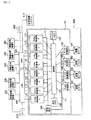
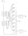
まず、本実施の形態に係る記憶装置システムの全体構成を示すブロック図を図1に示す。
(全体構成例)
記憶装置システム600は、記憶デバイス制御装置100と記憶デバイス300とを備えている。記憶デバイス制御装置100は、情報処理装置200から受信したコマンドに従って記憶デバイス300に対する制御を行う。例えば情報処理装置200からデータの入出力要求を受信して、記憶デバイス300に記憶されているデータの入出力のための処理を行う。データは、記憶デバイス300が備えるディスクドライブにより提供される物理的な記憶領域上に論理的に設定される記憶領域である論理ボリューム(Logical Unit)(以下、LUと記す)に記憶されている。また、記憶デバイス制御装置100は、情報処理装置200との間で、記憶装置システム600を管理するための各種コマンドの授受も行う。
First, FIG. 1 is a block diagram showing the overall configuration of the storage device system according to the present embodiment.
(Overall configuration example)
The
情報処理装置200はCPU(Central Processing Unit)やメモリを備えたコンピュータである。情報処理装置200が備えるCPUにより各種プログラムが実行されることによりさまざまな機能が実現される。情報処理装置200は、例えばパーソナルコンピュータやワークステーションであることもあるし、メインフレームコンピュータであることもある。
The
図1において、情報処理装置1乃至3(200)は、LAN(Local Area Network)400を介して記憶デバイス制御装置100と接続されている。LAN400は、インターネットとすることもできるし、専用のネットワークとすることもできる。LAN400を介して行われる情報処理装置1乃至3(200)と記憶デバイス制御装置100との間の通信は、例えばTCP/IPプロトコルに従って行われる。情報処理装置1乃至3(200)からは、記憶装置システム600に対して、ファイル名指定によるデータアクセス要求(ファイル単位でのデータ入出力要求。以下、ファイルアクセス要求と記す)が送信される。
In FIG. 1,
LAN400にはバックアップデバイス910が接続されている。バックアップデバイス910は具体的にはMOやCD-R、DVD-RAMなどのディスク系デバイス、DATテープ、カセットテープ、オープンテープ、カートリッジテープなどのテープ系デバイスである。バックアップデバイス910は、LAN400を介して記憶デバイス制御装置100との間で通信を行うことにより、記憶デバイス300に記憶されているデータのバックアップデータを記憶する。またバックアップデバイス910は情報処理装置1(200)と接続されるようにすることもできる。この場合は情報処理装置1(200)を介して記憶デバイス300に記憶されているデータのバックアップデータを取得するようにする。
A
記憶デバイス制御装置100は、チャネル制御部1乃至4(110)を備える。記憶デバイス制御装置100は、チャネル制御部1乃至4(110)によりLAN400を介して情報処理装置1乃至3(200)からのファイルアクセス要求を個々に受け付ける。すなわち、チャネル制御部1乃至4(110)には、個々にLAN400上のネットワークアドレス(例えば、IPアドレス)が割り当てられていてそれぞれが個別にNASとして振る舞い、個々のNASがあたかも独立したNASが存在するかのように、NASとしてのサービスを情報処理装置1乃至3(200)に提供することができる。以下、チャネル制御部1乃至4(110)をCHNと記す。このように1台の記憶装置システム600に個別にNASとしてのサービスを提供するチャネル制御部1乃至4(110)を備えるように構成したことで、従来、独立したコンピュータで個々に運用されていたNASサーバが一台の記憶システム600に集約される。そして、これにより記憶装置システム600の統括的な管理が可能となり、各種設定・制御や生涯管理、バージョン管理といった保守業務の効率化が図られる。
The storage
なお、本実施の形態に係る記憶デバイス制御装置100のチャネル制御部1乃至4(110)は、後述するように、一体的にユニット化された回路基板上に形成されたハードウェアおよびこのハードウェアにより実行されるオペレーティングシステム(以下、OSと記す)やこのOS上で動作するアプリケーションプログラム、あるいはこのハードウェアにより実行される実行可能オブジェクトコードなどのソフトウェアにより実現される。このように本実施例の記憶装置システム600では、従来ハードウェアの一部として実装されてきた機能がソフトウェアにより実現されている。このため、本実施例の記憶装置システム600では柔軟性に富んだシステム運用が可能となり、多様で変化の激しいユーザニーズによりきめ細かなサービスを提供することが可能となる。
Note that the
情報処理装置3乃至4(200)はSAN(Storage Area Network)500を介して記憶デバイス制御装置100と接続されている。SAN500は、記憶デバイス300が提供する記憶領域におけるデータの管理単位であるブロックを単位として情報処理装置3乃至4(200)との間でデータの授受を行うためのネットワークである。SAN500を介して行われる情報処理装置3乃至4(200)と記憶デバイス制御装置100との間の通信は、一般にファイバチャネルプロトコルに従って行われる。情報処理装置3乃至4からは、記憶装置システム600に対して、ファイバチャネルプロトコルに従ってブロック単位のデータアクセス要求(以下、ブロックアクセス要求と記す)が送信される。
The
SAN500にはSAN対応のバックアップデバイス900が接続されている。SAN対応バックアップデバイス900は、SAN500を介して記憶デバイス制御装置100との間で通信を行うことにより、記憶デバイス300に記憶されているデータのバックアップデータを記憶する。
A SAN-
情報処理装置5(200)は、LAN400やSAN500等のネットワークを介さずに記憶デバイス制御装置100と接続されている。情報処理装置5(200)としては例えばメインフレ−ムコンピュータとすることができる。情報処理装置5(200)と記憶デバイス制御装置100との間の通信は、例えばFICON(Fibre Connection)(登録商標)やESCON(Enterprise System Connection)(登録商標)、ACONARC(Advanced Connection Architecture)(登録商標)、FIBARC(Fibre Connection Architecture)(登録商標)などの通信プロトコルに従って行われる。情報処理装置5(200)からは、記憶装置システム600に対して、これらの通信プロトコルに従ってブロックアクセス要求が送信される。
The information processing apparatus 5 (200) is connected to the storage
記憶デバイス制御装置100は、チャネル制御部7乃至8(110)により情報処理装置5(200)との間で通信を行う。以下、チャネル制御部7乃至8(110)をCHAと記す。
The storage
SAN500には記憶装置システム600の設置場所(プライマリサイト)とは遠隔した場所(セカンダリサイト)に設置される他の記憶装置システム610が接続している。記憶装置システム610は、後述するレプリケーション又はリモートコピーの機能におけるデータの複製先の装置として利用される。なお、記憶装置システム610はSAN500以外にもATMなどの通信回線により記憶装置システム600に接続していることもある。この場合には例えばチャネル制御部110として上記通信回線を利用するためのインタフェース(チャネルエクステンダ)を備えるチャネル制御部110が採用される。
(記憶デバイス)
記憶デバイス300は、多数のディスクドライブ(物理ディスク)を備えており、情報処理装置200に対して記憶領域を提供する。データは、ディスクドライブにより提供される物理的な記憶領域上に論理的に設定される記憶領域であるLUに記憶されている。ディスクドライブとしては、例えばハードディスク装置やフレキシブルディスク装置、半導体記憶装置等さまざまなものを用いることができる。なお、記憶デバイス300は例えば複数のディスクドライブによりディスクアレイを構成するようにすることもできる。この場合、情報処理装置200に対して提供される記憶領域は、RAIDにより管理された複数のディスクドライブにより提供されるようにすることもできる。
The
(Storage device)
The
記憶デバイス制御装置100と記憶デバイス300との間は図1のように直接に接続される形態とすることもできるし、ネットワークを介して接続するようにすることもできる。さらに記憶デバイス300は記憶デバイス制御装置100と一体として構成されることもできる。
The storage
記憶デバイス300に設定されるLUには、情報処理装置200からアクセス可能なユーザLUや、チャネル制御部110の制御のために使用されるシステムLU等がある。システムLUにはCHN110で実行されるOSも格納される。また各LUにはチャネル制御部110が対応付けられている。これによりチャネル制御部110ごとにアクセス可能なLUが割り当てられている。また上記対応付けは、複数のチャネル制御部110で一つのLUを共有するようにすることもできる。なお以下において、ユーザLUやシステムLUをそれぞれユーザディスク、システムディスク等とも記す。
(記憶デバイス制御装置)
記憶デバイス制御装置100は、チャネル制御部110、共有メモリ120、キャッシュメモリ130、ディスク制御部140、管理端末160及び接続部150を備える。
The LU set in the
(Storage device controller)
The storage
チャネル制御部110は、情報処理装置200との間で通信を行うための通信インタフェースを備え、情報処理装置200との間でデータ入出力コマンド等を授受する機能を備える。例えばCHN110は情報処理装置1乃至3(200)からのファイルアクセス要求を受け付ける。これによる記憶装置システム600はNASとしてのサービスを情報処理装置1乃至3(200)に提供することができる。またCHF110は情報処理装置3乃至4(200)からのファイバチャネルプロトコルに従ったブロックアクセス要求を受け付ける。これにより記憶装置システム600は高速アクセス可能なデータ記憶サービスを情報処理装置3乃至4(200)に対して提供することができる。またCHA110は情報処理装置5(200)からのFICONやESCON、ACONARC、FIBERC等のプロトコルに従ったブロックアクセス要求を受け付ける。これにより記憶装置システム600は情報処理装置5(200)のようなメインフレームコンピュータに対してもデータ記憶サービスを提供することができる。
The
各チャネル制御部110は、管理端末160とともに内部LAN151等の通信網で接続されている。これによりチャネル制御部110に実行させるマイクロプログラム等を管理端末160から送信しインストールすることが可能となっている。チャネル制御部110の構成については後述する。
Each
接続部150はチャネル制御部110、共有メモリ120、キャッシュメモリ130及びディスク制御部140と接続されている。チャネル制御部110、共有メモリ120、キャッシュメモリ130及びスク制御部140間でのデータやコマンドの授受は、接続部150を介することにより行われる。接続部150は、例えば高速スイッチングによりデータ伝送を行う超高速クロスバスイッチなどのスイッチ、又はバス等で構成される。チャネル制御部110同士がスイッチで接続されていることで、個々のコンピュータ上で動作するNASサーバがLANを通じて接続する従来の構成に比べてチャネル制御部110間の通信パフォーマンスが大幅に向上している。また、これにより高速なファイル共有機能や高速フェイルオーバなどが可能となる。
The
共有メモリ120およびキャッシュメモリ130は、チャネル制御部110、
ディスク制御部140により共有される記憶メモリである。共有メモリ120は主に制御情報やコマンド等を記憶する為に利用されるのに対し、キャッシュメモリ130は主にデータを記憶するために利用される。
The shared
A storage memory shared by the
例えば、あるチャネル制御部110が情報処理装置200から受信したデータ入出力コマンドが書き込みコマンドであった場合には、当該チャネル制御部110は、書き込みコマンドを共有メモリ120に書き込むとともに、情報処理装置200から受信した書き込みデータをキャッシュメモリ130に書き込む。一方、ディスク制御部140は共有メモリ120を監視しており、共有メモリ120に書き込みコマンドが書き込まれたことを検出すると、当該コマンドに従ってキャッシュメモリ130から書き込みデータを読み出して記憶デバイス300に書き込む。
For example, when a data input / output command received by a certain
また、例えば、あるチャネル制御部110が情報処理装置200から受信したデータ入出力コマンドが読み出しコマンドであった場合には、当該チャネル制御部110は、読み出しコマンドを共有メモリ120に書き込むとともに、情報処理装置200から読み出しコマンドによって要求されたデータをキャッシュメモリ130から読み出す。仮に読み出しコマンドによって要求されたデータがキャッシュメモリ130に書き込まれていなかった場合、チャネル制御部110又はディスク制御部140は、読み出しコマンドによって要求されたデータを記憶デバイス300から読み出して、キャッシュメモリ130に書き込む。
For example, when a data input / output command received by a certain
なお、上記の本実施の形態においては、共有メモリ120及びキャッシュメモリ130がチャネル制御部110及びディスク制御部140に対して独立に設けられていることについて記載されているが、本実施の形態はこの場合に限られるものでなく、共有メモリ120又はキャッシュメモリ130がチャネル制御部110及びディスク制御部140の各々に分散されて設けられることも好ましい。この場合、接続部150は、分散された共有メモリ又はキャッシュメモリを有するチャネル制御部110及びディスク制御部140を相互に接続させることになる。
In the above-described embodiment, it is described that the shared
ディスク制御部140は、記憶デバイス300の制御を行う。例えば上述のように、チャネル制御部110が情報処理装置200から受信したデータ書き込みコマンドに従って記憶デバイス300へデータの書き込みを行う。また、チャネル制御部110により送信された論理アドレス指定によるLUへのデータアクセス要求を、物理アドレス指定による物理ディスクへのデータアクセス要求に変換する。記憶デバイス300における物理ディスクがRAIDにより管理されている場合には、RAID構成に従ったデータのアクセスを行う。またディスク制御部140は、記憶デバイス300に記憶されたデータの複製管理の制御やバックアップ制御を行う。さらにディスク制御部140は、災害発生時のデータ消失防止(ディザスタリカバリ)などを目的として、プライマリサイトの記憶装置システム600のデータの複製をセカンダリサイトに設置された他の記憶装置システム610にも記憶する制御(レプリケーション機能、またはリモートコピー機能)なども行う。
The
各ディスク制御部140は管理端末160とともに内部LAN151等の通信網で接続されており、相互に通信を行うことが可能である。これにより、ディスク制御部140に実行させるマイクロプログラム等を管理端末160から送信しインストールすることが可能となっている。ディスク制御部140の構成については後述する。
(管理端末)
管理端末160は記憶装置システム600を保守・管理するためのコンピュータである。管理端末160を操作することにより、例えば記憶デバイス300内の物理ディスク構成の設定や、LUの設定、チャネル制御部110において実行されるマイクロプログラムのインストール等を行うことができる。ここで、記憶デバイス300内の物理ディスク構成の設定としては、例えば物理ディスクの増設や減設、RAID構成の変更(RAID1からRAID5への変更等)等を行うことができる。さらに管理端末160からは、記憶装置システム600の動作状態の確認や故障部位の特定、チャネル制御部110で実行されるOSのインストール等の作業を行うこともできる。また管理端末160はLANや電話回線等で外部保守センタと接続されており、管理端末160を利用して記憶装置システム600の障害監視を行ったり、障害が発生した場合に迅速に対応することも可能である。障害の発生は例えばOSやアプリケーションプログラム、ドライバソフトウェアなどから通知される。この通知はHTTPプロトコルやSNMP(Simple Network Management Protocol)、電子メールなどにより行われる。これらの設定や制御は、管理端末160で動作するWebサーバが提供するWebページをユーザインタフェースとしてオペレータなどにより行われる。オペレータ等は、管理端末160を操作して障害監視する対象や内容の設定、障害通知先の設定などを行うこともできる。
Each
(Management terminal)
The
管理端末160は記憶デバイス制御装置100に内蔵されている形態とすることもできるし、外付けされている形態とすることもできる。また管理端末160は、記憶デバイス制御装置100及び記憶デバイス300の保守・管理を専用に行うコンピュータとすることもできるし、汎用のコンピュータに保守・管理機能を持たせたものとすることもできる。
The
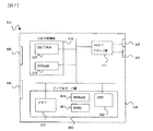
管理端末160の構成を示すブロック図を図2に示す。
A block diagram showing the configuration of the
管理端末160は、CPU161、メモリ162、ポート163、記録媒体読み取り装置164、入力装置165、出力装置166及び記憶装置168を備える。
The
CPU161は、管理端末160の全体の制御を司るもので、メモリ162に格納されたプログラム162cを実行することにより上記Webサーバとしての機能等を実現する。メモリ162には、物理ディスク管理テーブル162aとLU管理テーブル162bとプログラム162cとが記憶されている。
The
物理ディスク管理テーブル162aは、記憶デバイス300に備えられる物理ディスク(ディスクドライブ)を管理するためのテーブルである。物理ディスク管理テーブル162aを図3に示す。図3においては、記憶デバイス300が備える多数の物理ディスクのうち、ディスク番号#001乃至#006までが示されている。それぞれの物理ディスクに対して、容量、RAID構成、使用状況が示されている。
The physical disk management table 162a is a table for managing physical disks (disk drives) provided in the
LU管理テーブル162bは、上記物理ディスク上に論理的に設定されるLUを管理するためのテーブルである。LU管理テーブル162bを図4に示す。図4においては、記憶デバイス300上に設定される多数のLUのうち、LU番号#1乃至#3までが示されている。それぞれのLUに対して、物理ディスク番号、容量、RAID構成が示されている。
The LU management table 162b is a table for managing LUs logically set on the physical disk. The LU management table 162b is shown in FIG. FIG. 4 shows
記憶媒体読取装置164は、記録媒体167に記録されているプログラムやデータを読み取るための装置である。読み取られたプログラムやデータはメモリ162や記憶装置168に格納される。従って、例えば記録媒体167に記録されたプログラム162cを、記録媒体読取装置164を用いて記録媒体167から読み取って、目盛り162や記憶装置168に格納するようにすることができる。記録媒体167としてはフレキシブルディスクやCD−ROM、半導体メモリ等を用いることができる。記録媒体読取装置162は管理端末160に内蔵されている形態とすることもできる。記憶装置168は、例えばハードディスク装置やフレキシブルディスク装置、半導体記憶装置等である。入力装置165は、オペレータ等による管理端末160へのデータ入力等のために用いられる。入力装置165としては例えばキーボードやマウス等が用いられる。出力装置166は、情報を外部に出力するための装置である。出力装置166としては例えばディスプレイやプリンタ等が用いられる。ポート163は内部LAN151に接続されており、これにより管理端末160はチャネル制御部110やディスク制御部140等と通信を行うことができる。またポート163は、LAN400に接続するようにすることもできるし、電話回線に接続するようにすることもできる。
(外観図)
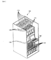
次に、本実施の形態に係る記憶装置システム600の外観構成を図5に示す。
また、記憶デバイス制御装置100の外観構成を図6に示す。
The storage
(External view)
Next, an external configuration of the
Also, an external configuration of the storage
図5に示すように、本実施の形態に係る記憶装置システム600は記憶デバイス制御装置100および記憶デバイス300がそれぞれの筐体に収められた形態をしている。記憶デバイス制御装置100の筐体の両側に記憶デバイス300の筐体が配置されている。
As shown in FIG. 5, the
記憶デバイス制御装置100は、正面中央部に管理端末160が備えられている。管理端末160はカバーで覆われており、図6に示すようにカバーを開けることにより管理端末160を使用することができる。なお図6に示した管理端末160はいわゆるノート型パーソナルコンピュータの形態をしているが、どのような形態とすることも可能である。
The storage
管理端末160の下部には、チャネル制御部110を装着するためのスロットが設けられている。各スロットにはチャネル制御部110のボードが装着される。本実施の形態に係る記憶装置システム600においては、例えばスロットは8つあり、図5および図6には8つのスロットにチャネル制御部110を装着するためのガイドレールが設けられている。ガイドレールに沿ってチャネル制御部110をスロットに挿入することにより、チャネル制御部110を記憶デバイス制御装置100に装着することができる。また各スロットに装着されたチャネル制御部110は、ガイドレールに沿って手前方向に引き抜くことにより取り外すことができる。また各スロットの奥手方向正面部には、各チャネル制御部110を記憶デバイス制御装置100と電気的に接続するためのコネクタが設けられている。チャネル制御部110には、CHN、CHF、CHAがあるが、いずれのチャネル制御部110もサイズやコネクタの位置、コネクタのピン配列等に互換性をもたせているため、8つのスロットにはいずれのチャネル制御部110も装着することが可能である。従って、例えば8つのスロット全てにCHN110を装着するようにすることもできる。また例えば図1に示したように、4枚のCHN110と、2枚のCHF110と、2枚のCHA110とを装着するようにすることもできる。チャネル制御部110を装着しないスロットを設けることもできる。
A slot for mounting the
なお、上述したように、チャネル制御部110は上記各スロットに装着可能なボード、すなわち同一のユニットに形成された一つのユニットとして提供されるが、上記同一のユニットは複数枚数の基板から構成されているようにすることもできる。つまり、複数枚数の基板から構成されていても、各基板が相互に接続されて一つのユニットとして構成され、記憶デバイス制御装置100のスロットに対して一体的に装着できる場合は、同一の回路基板の概念に含まれる。
As described above, the
ディスク制御部140や共有メモリ120等の、記憶デバイス制御装置100を構成する他の装置については図5および図6には示されていないが、記憶デバイス制御装置100の背面側当に装着されている。
Other devices constituting the storage
また記憶デバイス制御装置100には、チャネル制御部110とらおから発生する熱を放出するためのファン170が設けられている。ファン170は記憶デバイス制御装置100の上面部に設けられるほか、チャネル制御部110用スロットの上部にも設けられている。
In addition, the storage
ところで、筐体に収容されて構成される記憶デバイス制御装置100および記憶デバイス300としては、例えばSAN製品として製品化されている従来構成の装置を利用することができる。特に上記のようにCHNのコネクタ形状を従来構成の筐体に設けられているスロットにそのまま装着できる形状とすることとで従来構成の装置をより簡単に利用することができる。つまり、本実施例の記憶装置システム600は、既存の製品を利用することで容易に構築することができる。
By the way, as the storage
さらに、本実施の形態によれば、記憶装置システム600内にCHN110、
CHF110、CHA110を混在させて装着させることにより、異種ネットワークに接続される記憶装置システムを実現できる。具体的には、記憶装置システム600は、CHN110を用いてLAN140に接続し、かつCHF110を用いてSAN500に接続するという、SAN−NAS統合記憶装置システムである。
(チャネル制御部)
本実施の形態に係る記憶装置システム600は、上述の通りCHN110により情報処理装置1乃至3(200)からのファイルアクセス要求を受け付け、NASとしてのサービスを情報処理装置1乃至3(200)に提供する。
Furthermore, according to the present embodiment, the
By mounting
(Channel control unit)
The
CHN110のハードウェア構成を図7に示す。この図に示すようにCHN110のハードウェアは一つのユニットで構成される。以下、このユニットのことをNASボードと記す。NASボードは一枚もしくは複数枚の回路基板を含んで構成される。より具体的には、NASボードは、ネットワークインタフェース部111、入出力制御部114、ボード接続用コネクタ116、通信コネクタ117及びファイルサーバ部800を備え、これらが同一のユニットに形成されて構成されている。さらに、入出力制御部114は、NVRAM(Non Volatile RAM)115及びI/O(Input/Output)プロセッサ119を有する。
The hardware configuration of the
ネットワークインタフェース部111は、情報処理装置200との間で通信を行うための通信インタフェースを備えている。CHN110の場合は、例えばTCP/IPプロトコルに従って情報処理装置200から送信されたファイルアクセス要求を受信する。通信コネクタ117は、情報処理装置200との間で通信を行うためのコネクタである。CHN110の場合は、LAN400に接続可能なコネクタであり、例えばイーサネット(登録商標)に対応している。
The
ファイルサーバ部800は、CPU112、メモリ113、BIOS(Basic Input/Output System)801及びNVRAM804を有する。CPU112は、CHN110をNASボードとして機能させるための制御を司る。CPU112は、NFS又はCIFS等のファイル共有プロトコル及びTCP/IPの制御、ファイル指定されたファイルアクセス要求の解析、メモリ113内の制御情報へのファイル単位のデータと記憶デバイス300内のLUとの変換テーブル(図示せず)を用いた相互変換、記憶デバイス300内のLUに対するデータ書き込み又は読み出し要求の生成、データ書き込み又は読み出し要求のI/Oプロセッサ119への送信等を処理する。BIOS801は、例えばCHN110に電源が投入された際に、CPU112を起動する過程で最初にメモリ113にロードされ実行されるソフトウェアであり、例えばフラッシュメモリなどの不揮発性の媒体に保存されてCHN110上に実装されている。CPU112は、BIOS801からメモリ113上に読み込まれたソフトウェアを実行することにより、CHN21上のCPU112が関係する部分の初期化、診断などを行うことができる。さらに、CPU112は、BIOS801からI/Oプロセッサ119にコマンドなどの指示を発行することにより、記憶デバイス300から所定のプログラム、例えばOSのブート部などをメモリ113に読み込むことができる。読み込まれたOSのブート部は、さらに記憶デバイス300に格納されているOSの主要部分をメモリ113に読み込む動作をし、これによりCPU112上でOSが起動され、例えばファイルサーバとしての処理が実行できるようになる。また、ファイルサーバ部800は、PXE(Preboot eXecution Environment)などの規約にしたがうネットワークブートローダを格納するNVRAM804を実装し、後述するネットワークブートを行わせることも可能である。
The
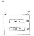
メモリ113にはさまざまなプログラムやデータが記憶される。例えば図8に示すメタデータ730やロックテーブル720、また図14に示されるNASマネージャ706等の各種プログラムが記憶される。メタデータ730は、ファイルシステムが管理しているファイルに対応させて生成される情報である。メタデータ730には例えばファイルのデータが記憶されているLU上のアドレスやデータサイズなど、ファイルの保管場所を特定するための情報が含まれる。メタデ−タ730にはファイルの容量、所有者、更新時刻等の情報が含まれることもある。また、メタデータ730はファイルだけでなくディレクトリに対応させて生成されることもある。メタデータ730の例を図9に示す。メタデータ730は記憶デバイス300上の各LUにも記憶されている。
The
ロックテーブル720は、情報処理装置1乃至3(200)からのファイルアクセスに対して排他制御を行うためのテーブルである。排他制御を行うことにより情報処理装置1乃至3(200)でファイルを共用することができる。ロックテーブル720を図10に示す。図10に示すようにロックテーブル720には、ファイルロックテーブル721とLUロックテーブル722とがある。ファイルロックテーブル721は、ファイルごとにロックが掛けられているか否かを示すためのテーブルである。いずれかの情報処理装置200によりあるファイルがオープンされている場合に当該ファイルにロックが掛けられる。ロックが掛けられたファイルに対する他の情報処理装置200によるアクセスは禁止される。LUロックテーブル722は、LUごとにロックが掛けられているか否かを示すためのテーブルである。いずれかの情報処理装置200により、あるLUに対するアクセスが行われている場合に当該LUにロックが掛けられる。ロックが掛けられたLUに対する他の情報処理装置200によるアクセスは禁止される。
The lock table 720 is a table for performing exclusive control on file access from the
入出力制御部114は、ディスク制御部140キャッシュメモリ130、共有メモリ120及び管理端末160との間でデータやコマンドの授受を行う。入出力制御部114はI/Oプロセッサ119及びNVRAM115を備えている。I/Oプロセッサ119は例えば1チップのマイコンで構成される。I/Oプロセッサ119は、記憶デバイス300内のLUに対するデータ書き込み又は読み出し要求やデータの授受を制御し、CPU112とディスク制御部140との間の通信を中継する。NVRAM115はI/Oプロセッサ119の制御を司るプログラムを格納する不揮発性メモリである。NVRAM115に記憶されるプログラムの内容は、管理端末160や、後述するNASマネージャ706からの指示により書き込みや書き換えを行うことができる。
The input /
図11は、CHN110上のCPU112とI/Oプロセッサ119との通信経路について具体的に示す。I/Oプロセッサ119と、CPU112は、CHN110上に実装された通信メモリ802、ハードウェアレジスタ群803で物理的に接続されている。通信メモリ802およびハードウェアレジスタ群803は、それぞれCPU112およびI/Oプロセッサ119のいずれからもアクセスが可能である。ハードウェアレジスタ群803は、CPU112に対して電源を投入又は切断する回路に接続される。これにより、I/Oプロセッサ119は、ハードウェアレジスタ群803にアクセスすることによって、ハードウェアレジスタ群803を介してCPU112の電源を操作することが可能となる。ハードウェアレジスタ群803は、必要に応じて、CPU112あるいはI/Oプロセッサ119がハードウェアレジスタ群803にアクセスを行った際に、アクセス対象の相手先に割り込み信号などを生成して、アクセスが行われたことを通知する等の複数の機能を有する。これら複数の機能は、ハードウェアレジスタ群803を構成する各レジスタにそれぞれハードウェア的に割り当てられる。
FIG. 11 specifically shows a communication path between the
図12は、CPU112とI/Oプロセッサ119とを、内部LAN151によって接続しているハードウェア構成図である。このように、CPU112とI/Oプロセッサ119とは、ともに内部LAN151によっても接続されており、内部LAN151を介して管理端末160との通信が可能である。これにより、例えば、CPU112は、NVRAM804に予め格納されているネットワークブートローダを実行することにより、管理端末160から起動用のソフトウェアをメモリ113にダウンロードし、起動用のソフトウェアを実行することができる。これによって例えば、管理端末160をサーバとし、CPU112をクライアントとするネットワークブートプロセスが実行される。なお、ネットワークブートは、例えばPXEなどの規約に従い、クライアント上のネットワークブートローダと管理端末160上で動作するサーバとが、IPプロトコル、DHCP、TFTP、FTPなどのプロトコルを組み合わせることにより、LAN上の管理端末160に存在するOSのブートイメージを起動及び実行する方法である。
FIG. 12 is a hardware configuration diagram in which the
図13は、ディスク制御部140のハードウェア構成を示すブロック図である。既に述べた通り、ディスク制御部は、記憶デバイス300に接続されるとともに接続部150を介してCHN112に接続され、ディスク制御部140独自で、又はCHN112によって制御されることにより、記憶デバイス300に対してデータの読み書きを行う。
FIG. 13 is a block diagram illustrating a hardware configuration of the
ディスク制御部140は、インタフェース部141、メモリ143、CPU142、NVRAM144及びボード接続用コネクタ145を備え、これらが一体的なユニットとして形成されている。
The
インタフェース部141は、接続部150を介してチャネル制御部110等と通信を行うための通信インタフェース、記憶デバイス300と通信を行うための通信インタフェース、内部LAN151を介して管理端末160と通信を行うための通信インタフェースを備えている。
The
CPU142は、ディスク制御部140全体の制御を司るとともに、チャネル制御部110や記憶デバイス300、管理端末160との間の通信を行う。メモリ143やNVRAM144に格納された各種プログラムを実行することにより本実施の形態に係るディスク制御部140の機能が実現される。ディスク制御部140により実現される機能としては、記憶デバイス300の制御やRAID制御、記憶デバイス300に記憶されたデータの複製管理やバックアップ制御、リモートコピー制御等である。
The
NVRAM144はCPU142の制御を司るプログラムを格納する不揮発性メモリである。NVRAM144に記憶されるプログラムの内容は、管理端末160や、NASマネージャ706からの指示により書き込みや書き換えを行うことができる。
The
またディスク制御部140はボード接続用コネクタ145を備えている。ボード接続用コネクタ145が記憶デバイス制御装置100側のコネクタと接続することにより、ディスク制御部140は、記憶デバイス制御装置100と電気的に接続される。
(ソフトウェア構成図)
図14は、本実施の形態に係る記憶装置システム600におけるソフトウェア構成図である。既に述べたように、CHN110上には、CPU112およびI/Oプロセッサ119が存在する。CPU112およびI/Oプロセッサ119は、それぞれ1つずつであってもよいし、それぞれ複数存在してもよい。CPU112上では、OS701とNASマネージャ706等の多様なアプリケーションとが実行されることにより、CPU112はNASサーバとして動作する。I/Oプロセッサ119上では、コントローラとしてのマイクロプログラムが動作している。ディスク制御部140では、RAID制御部740がCPU142上で動作している。管理端末160の上では、CPU161がネットブートサーバ703として動作する。ネットブートサーバ703は、記録媒体167又は記憶装置168等から内部LAN151を介して、ミニカーネル704、OSイメージ705等をCHN110上のCPU112に転送する。ネットブートサーバ703は、例えば、DHCP(Dynamic Host Configuration Protocol)サーバなどを有し、CPU112、CPU161及びI/Oプロセッサ119にIPアドレス又はMACアドレスを割り当てる等して、管理端末160とCPU112、CPU161及びI/Oプロセッサ119との間の転送を行う。ネットブートを行うとき、例えば、CPU112は、クライアントとして、ネットブートサーバ703に対してDHCP要求及びファイル転送要求等を要求する。CPU112は、ネットブートの手順を経て、CPU112上でミニカーネル704を動作させることになる。最終的に、CPU112は、I/Oプロセッサ119を経由してOSイメージ705を記憶デバイス300にインストールさせる。
The
(Software configuration diagram)
FIG. 14 is a software configuration diagram of the
なお、図14は、情報処理装置200のソフトウェア構成についても明示してある。情報処理装置200は、NFS(Network File System)711を有するもの、又はCIFS(Common Internet File System)713を有するものが存在する。NFS711は、主にUNIX(登録商標)系のオペーティングシステム714によって用いられるファイル共有プロトコルであり、CIFS713は、主にWindows(登録商標)系のOS715によって用いられるファイル共有プロトコルである。
(記憶装置システムのシステム領域)
図15は、情報処理装置200内部における、ソフトウェアや情報の格納領域を示している。CPU112のソフトウェアは、ネットワークインストールなどによって記憶デバイス300に格納されている。ここで記憶デバイスをLU(Logical Unit)1からLU6で表す。ここでCHN1のCPU112のソフトウェアがLU1に格納され、CHN2のCPU112のソフトウェアがLU4に格納されているものとする。LU2はCHN1の情報格納エリアとして予約されており、LU5はCHN2の情報格納エリアとして予約されている。またLU3は、CHN1のCPU112のソフトウェアと、CHN2のCPU112のソフトウェアが連携して動作するために必要な情報を格納する共有LUである。さらにLU6は、LU3の情報をバックアップするための共有LUバックアップLUである。
FIG. 14 also clearly shows the software configuration of the
(System area of storage system)
FIG. 15 shows a storage area for software and information in the
IOプロセッサ119は、CPU112からの指示を受けるか、管理端末160からの指示を受けることによって、共有LUから共有LUバックアップへのデータ転送を行うことができる。また、ディスク制御部140が共有LUから共有LUバックアップへのデータ転送を独自に行うこともできる。
The
これにより、LU3の情報を使って例えばCHN1とCHN2との間でフェイルオーバなどのオペレーションを行おうとした際、LU3が使用不能であった場合に、LU3の情報を使用する替わりにLU6の情報を使用することによって、問題なくフェイルオーバ動作を続行することができる。 As a result, when an operation such as failover is performed between the CHN1 and CHN2 using the LU3 information, for example, if the LU3 is not usable, the LU6 information is used instead of the LU3 information. By doing so, the failover operation can be continued without any problem.
さらに、IOプロセッサ119は、CPU112からの指示を受けるか、管理端末160からの指示を受けることによって、LU1からLU4へ、LU5からLU2へと、互いに異なるCHNの情報格納エリアに対して、CPU112のソフトウェアをバックアップすることもできる。これにより例えばCHN1のCPU112のソフトウェア格納領域が使用不能になった場合に、LU1を保守員が交換した後に、CHN1のソフトウェアはインストールされていない状態に戻ってしまうが、CHN2のCPUから指示を行うことによって、LU4からソフトウェアを復元することができる。
Furthermore, the
(記憶装置システムのデータアクセス方式)
一般に、オペレーティングシステムから見て記憶装置上のデータに対するアクセス方式には2種類がある。ひとつはファイルシステムを使用したアクセスであり、もう一つはファイルシステムを使用しないアクセスである。オペレーティングシステムは、システムコールと呼ばれる方法などにより、ファイルシステムを使用することなくデータへのアクセスを行うこともできる。ファイルシステムを使用しないアクセスは、記憶装置上のデータの位置を直接指定してアクセスすることになる。記憶装置上のデータの位置を直接指定してアクセスする場合、特段の処理を施さない場合は、複数のオペレーティングシステムから同時に同じ位置へのアクセスが発生した場合排他を行うことが出来ないため、オペレーティングシステム同士、あるいは複数のコントローラマイクロプログラム間、あるいは複数のディスク制御部間で何らかの手段でお互いに排他制御を行う必要がある。
(Data access method for storage system)
Generally, there are two types of access methods for data on a storage device as seen from the operating system. One is access using the file system, and the other is access without using the file system. The operating system can also access data without using a file system by a method called a system call. Access without using the file system is performed by directly specifying the position of data on the storage device. When accessing data by directly specifying the location of the data on the storage device, if no special processing is performed, it is impossible to perform exclusion if multiple operating systems access the same location at the same time. It is necessary to perform mutually exclusive control between systems, between a plurality of controller microprograms, or between a plurality of disk control units by some means.
ファイルシステムとは、記憶装置上のデータに対する管理の方式、あるいは記憶装置上のデータを管理するソフトウェア、あるいは記憶装置上に格納された、記憶装置上のデータの管理情報などを指す一般的な用語である。通常オペレーティングシステムはファイルシステムを使用してデータにアクセスを行う。ファイルシステムのソフトウェアはデータの排他制御機能を通常実装しているため、複数のオペレーティングシステムが記憶装置上の同じ領域にあるデータを同時にアクセスしようとした場合でも、互いのファイルシステムの排他制御によってデータが保全される。ファイルシステムを用いてデータを管理する場合には、記憶装置上の領域に対してファイルシステムを定義し、定義したファイルシステムをオペレーティングシステムの管理用情報として登録したのちにファイルシステムに対してアクセス要求を行う必要がある。一般にファイルシステムの定義はファイルシステムの作成、ファイルシステムの登録はファイルシステムのマウントなどと呼ばれる。ファイルシステムは任意のタイミングで、オペレーティングシステムからの指示によりマウントを行ったり、マウントを取り消したりできる。マウントの取り消しはアンマウントという。 A file system is a general term indicating a management method for data on a storage device, software for managing data on the storage device, or management information of data on the storage device stored on the storage device. It is. Normally, the operating system uses a file system to access data. Since the file system software usually implements the data exclusive control function, even if multiple operating systems try to access data in the same area on the storage device at the same time, the data is controlled by mutual file system exclusive control. Is preserved. When managing data using a file system, define the file system for the area on the storage device, register the defined file system as operating system management information, and then request access to the file system. Need to do. Generally, file system definition is called file system creation, and file system registration is called file system mount. The file system can be mounted or unmounted at any time according to an instruction from the operating system. Unmounting is called unmounting.
通常、コントローラマイクロプログラムに対してI/Oなどの指示を直接行うのは、CPUで動作しているI/Oドライバである。オペレーティングシステムは通常ファイルシステムソフトウェアを使用して、I/Oドライバに対して、コントローラマイクロプログラムに向かって命令を発行するように要求する。この場合のアクセスはファイルシステムアクセスとなり、排他制御や、データの物理的格納位置についてはファイルシステムが管理する。また、オペレーティングシステムはファイルシステムソフトウェアを使用せずに、直接I/Oドライバに対して、コントローラマイクロプログラムに向かって命令を発行するように要求することもできる。この場合、データの位置や排他を管理するファイルシステムを使用しないため、オペレーティングシステムは何らかの手段でデータの位置を管理し、排他制御などを独自に行う必要がある。いずれの場合でも、コントローラマイクロプログラムから見ると、データの位置情報、転送サイズなどが指定された状態の要求がI/Oドライバから発行されてくることになる。これは、コントローラマイクロプログラムの立場からは、CPUからの要求がファイルシステムを使用したものか、そうでないのかの判断ができないことを意味する。
(CHNの動作方式)
本記憶装置において、高い可用性を保証するために、複数のCHNがひとつの組となって、互いに補完しあいながら動作することが可能である。これら複数のCHNによって作られる動作の単位をクラスタと呼ぶ。あるクラスタに属するCHNは、ユーザデータの格納されているLUへのパスを共有し、ユーザがクライアントからどのCHNに対して要求を発行しても、適切なLUへのアクセスができる状態になっている。ただしパスの定義は記憶装置システムのコントローラマイクロプログラムが認識する情報であるため、オペレーティングシステムが当該LUへアクセスするためには、通常はファイルシステムを使用しマウントを行う必要がある。パスが定義されていないとコントローラマイクロプログラムからオペレーティングシステムに対し当該LUの存在が伝達されないため、マウントも行えないが、パスが定義されていることによって、オペレーティングシステムがコントローラマイクロプログラムに対して問い合わせを行った際に、コントローラマイクロプログラムが当該LUの存在をオペレーティングシステムに伝達することができる。すなわち、オペレーティングシステムが当該LUにアクセスするためには、まずコントローラマイクロプログラムから当該LUへのアクセスパスを定義し、オペレーティングシステムがコントローラマイクロプログラムに対して使用可能なデバイスの問い合わせを行った際に当該LUの存在がコントローラマイクロプログラムから報告される必要があり、さらに、使用可能として報告されているデバイスの中から、オペレーティングシステムは最小で一つ、最大で報告されているデバイス全てについて、ファイルシステムの作成を行い、さらにそのファイルシステムをマウントすることによって実現される。ここでファイルシステムの作成とは、オペレーティングシステムが、当該デバイスに対して、ファイル名やディレクトリ名を指定してデータアクセスを行うことができるよう、ファイルやディレクトリの構造を定義し、その構造に対するアクセスのルールを定義し、これらの情報をシステム領域とデータ領域双方に記憶することを言う。本システムの場合システム領域はシステムLU内に存在し、データ領域はユーザLU内に存在する。オペレーティングシステムは、このルールに従ってファイルやディレクトリ構造を操作することによって、データにアクセスする。このアクセス方式をファイルシステムアクセスという。
Usually, it is an I / O driver operating on the CPU that directly instructs the controller microprogram such as I / O. The operating system typically uses file system software to request the I / O driver to issue instructions to the controller microprogram. Access in this case is file system access, and the file system manages exclusive control and physical storage location of data. The operating system can also directly request the I / O driver to issue instructions to the controller microprogram without using file system software. In this case, since a file system that manages the position and exclusion of data is not used, the operating system must manage the position of the data by some means and perform exclusive control independently. In either case, when viewed from the controller microprogram, a request in a state in which data position information, transfer size, and the like are specified is issued from the I / O driver. This means that from the standpoint of the controller microprogram, it cannot be determined whether the request from the CPU uses the file system or not.
(CHN operation method)
In this storage device, in order to guarantee high availability, a plurality of CHNs can operate as one set and complement each other. The unit of operation created by these multiple CHNs is called a cluster. A CHN belonging to a certain cluster shares a path to an LU in which user data is stored, and can access an appropriate LU even if a user issues a request to any CHN from a client. Yes. However, since the definition of the path is information recognized by the controller microprogram of the storage system, in order for the operating system to access the LU, it is usually necessary to mount using the file system. If the path is not defined, the presence of the LU is not transmitted from the controller microprogram to the operating system, so mounting is not possible. However, the operating system queries the controller microprogram because the path is defined. When done, the controller microprogram can communicate the presence of the LU to the operating system. In other words, in order for the operating system to access the LU, first, an access path from the controller microprogram to the LU is defined, and when the operating system makes an inquiry about available devices to the controller microprogram, The presence of the LU needs to be reported by the controller microprogram, and the operating system is at least one of the devices reported as available and the file system This is accomplished by creating and then mounting the file system. Here, creating a file system means defining the file and directory structure so that the operating system can access the device by specifying the file name and directory name, and accessing the structure. This rule is defined to store these information in both the system area and the data area. In the case of this system, the system area exists in the system LU, and the data area exists in the user LU. The operating system accesses the data by manipulating the file and directory structure according to this rule. This access method is called file system access.
(記憶装置システムの記憶装置に対するデータアクセス方法)
図16は、情報処理装置200において共有LUを複数のパーティションに分割し、それぞれを複製する様子を論理ブロック図で示している。
(Data access method for storage device of storage system)
FIG. 16 is a logical block diagram showing how the
共有LUは4個のパーティションに分割されており、同容量の共有LUバックアップLUも同じ容量ずつの4個のパーティションに分割されている。これらの設定は、CHNにオペレーティングシステムをインストールする際、管理端末160からの設定で共有LUおよび共有LUバックアップLUの初期化を行うよう指示することにより達成される。
(記憶装置システムのバックアップLU)
次に、実際に共有LUをバックアップする際の手順を、CHN1およびCHN5が共用している共有LUのパーティション部分のバックアップの例を用いて説明する。共有LUは共有LU311乃至314の4つのパーティションに分割される。パーティションの分割は、オペレーティングシステムの定義によって行われ、オペレーティングシステムからのアクセスによってのみ意味を持つ。共有LU311乃至314と、共有LUのバックアップ321乃至324は、それぞれCHN1およびCHN5からパスが定義されている。これは、CHN1のコントローラと、CHN5のコントローラから、共有LU311乃至314と、共有LUのバックアップ321乃至324にアクセスができることを意味する。この段階で、CHN1あるいはCHN5のオペレーティングシステムから、データブロックアクセス指示をCHN1、CHN5のコントローラに対して発行することによって、共有LU311乃至314と、共有LUのバックアップ321乃至324に対してデータの読み込み、あるいは書き出しの操作ができることを意味する。さらに、もしCHN1あるいはCHN5のオペレーティングシステムから共有LU311乃至314、共有LUのバックアップ321乃至324に対してファイルシステムを作成している場合、当該ファイルシステムをCHN1あるいはCHN5からマウントすれば、オペレーティングシステムは、共有LU311乃至314、共有LUのバックアップ321乃至324に対して、ファイルシステムを使用してデータの読み込み、書き出しを行うことができることになる。ここでは、ファイルシステムを使用したデータの読み込み、書き出しを行う例について述べる。CHN1、CHN2、CHN3,CHN5,CHN6,CHN7は、それぞれ自分が装着されているスロットの位置によって、アクセスするべきパーティションの位置を決定し、オペレーティングシステムはそれによって自分がアクセスするべき共有LU311乃至314と、共有LUのバックアップ321乃至324の場所を判定する。この例では、CHN1およびCHN5は、共有LU311と、共有LUのバックアップ321に対してアクセスすることが決定される。CHN1およびCHN5は、共有LU312乃至314と、共有LU322乃至324に対しては、オペレーティングシステムとしてはアクセスを行わない。
The shared LU is divided into four partitions, and the shared LU backup LU having the same capacity is also divided into four partitions each having the same capacity. These settings are achieved by instructing the initialization of the shared LU and the shared LU backup LU with the settings from the
(Storage system backup LU)
Next, the procedure for actually backing up the shared LU will be described using an example of backup of the partition portion of the shared LU shared by CHN1 and CHN5. The shared LU is divided into four partitions of shared
(バックアップLUの定義)
まず初めに、各CHNは、それぞれ独自の共有LU311乃至314を持つ。
共有LU311乃至314、共有LUのバックアップ321乃至324については、あらかじめ管理端末160からアクセスパスを定義しておく。CHNが複数存在する場合は、すべてのCHNに対して、これらの共有LU乃至311乃至314、共有LUのバックアップ321乃至324へのアクセスパスを定義しておく。
(Definition of backup LU)
First, each CHN has its own shared
For the shared
次に、システムに一番初めにNASを導入する際に、最初にCHNを実装するタイミングで、オペレーティングシステムを管理端末160からネットワークインストールする。この際、ネットワークインストールの作業の一環として、インストールプログラムによって、共有LU311乃至314、共有LUのバックアップ321乃至324の初期化を行う。またこの際に、共有LUを共有LU311乃至324、共有LUのバックアップを共有LUのバックアップ321乃至324というようにパーティションに分割し、それらの情報を共有LUに記憶させる。その作業が完了したのちに、オペレーティングシステムを、オペレーティングシステム用LUに管理端末160よりネットワークインストールする。
Next, when the NAS is first introduced into the system, the operating system is network-installed from the
以降、CHNを実装する際には、それぞれのCHNに対応するオペレーティングシステム用LUを順次初期化し、オペレーティングシステムをネットワークインストールしていくが、共有LU311乃至314、および共有LUのバックアップ321乃至324については、既に一度初期化してあるため以降は初期化しない。
Thereafter, when the CHN is mounted, the operating system LU corresponding to each CHN is sequentially initialized and the operating system is network-installed. The shared
(共有LUの用途)
共有LU311に格納されるデータは、たとえばCHN間で処理の引継ぎを行う際の引き継ぎデータなどが格納される。CHN1は、処理を行っている際に、CHNのIPアドレス等のクライアントからのアクセスに必要な情報、クライアント情報や動作アプリケーション情報、オペレーションシステム上のサービスやデーモンの動作状態などの処理情報を共有LU311に格納する。もしCHN1がハードウェア障害やソフトウェア障害などで使用不能になった場合、これをハートビート機能などでCHN5が検知すると、共有LU311に格納されている上記の情報を元に、CHN1が行っていた処理を肩代わりし実行する。これにより、CHN1にアクセスしていたクライアントは、引き続きCHN5にアクセスすることにより処理を継続できる。この動作をフェイルオーバという。
(共有LUのバックアップの必要性)
共有LU311は、通常RAIDシステムなどにより、物理的なハードディスクが1台故障しても動作が継続できるように設計されているが、予めRAIDとして用意された冗長度を超えた深刻度の故障が発生した場合などは、共有LU311は使用不能となる。この場合、さらにCHN1が故障した場合には、CHN5が処理を引き継ぐための情報を取得することができなくなる。このため共有LU311のデータを、共有LUのバックアップ321にコピーする必要が生じる。
(共有LUのバックアップ方式)
共有LUのバックアップには、例えばオペレーティングシステム上の汎用コマンドによって、コピーを行うことが考えられる。この場合、デバイスレベルでブロック単位でコピーを行うコマンドや、ファイル名を指定することによってファイル単位でコピーを行うコマンドなどがある。このコマンドを、ネットワーク上に存在するクライアントワークステーションやパーソナルコンピュータなどからオペレーティングシステムにログインし、端末を表示させて端末上で入力することにより、オペレーティングシステムに実行させることによってバックアップを実行する。これらのコマンドは、例えばオペレーティングシステムがUNIX(登録商標)である場合は、ファイル単位のコピーであればcpコマンド、またデバイス指定のブロック単位でのコピーであればddコマンドなどが挙げられる。
(Use of shared LU)
The data stored in the shared
(Need for backup of shared LU)
The shared
(Shared LU backup method)
For the backup of the shared LU, for example, it can be considered to perform a copy by a general-purpose command on the operating system. In this case, there are a command for copying in block units at the device level and a command for copying in file units by specifying a file name. This command is logged in to the operating system from a client workstation or personal computer that exists on the network, and the terminal is displayed and input on the terminal, so that the operating system executes the command to execute backup. For example, when the operating system is UNIX (registered trademark), these commands include a cp command for copying in units of files and a dd command for copying in units of blocks designated by a device.
また、一般的にオペレーティングシステムの設定により、これらのコマンドを定期的に実行するように指定することができる。これにより共有LUを定期的にバックアップすることができる。さらに、管理端末160からなどの指示によって、ディスク制御部140が持つディスクコピー機能を利用して、CHNのオペレーティングシステムやコントローラマイクロプログラムとは無関係に、共有LU全体を共有LUバックアップにコピーすることも可能である。また、指示を契機にコピーを行うのではなく、CHN1が初めから共有LU311と共有LUバックアップ321に同時に共有データを書き込むことにより、共有LU311または共有LUバックアップ321が使用不能になった場合に残りの情報を使用してCHN5にフェイルオーバをさせることも可能である。
In general, these commands can be designated to be executed periodically by setting of the operating system. As a result, the shared LU can be backed up regularly. Furthermore, the entire shared LU can be copied to the shared LU backup regardless of the CHN operating system or controller microprogram by using the disk copy function of the
(バックアップデータの使用)
バックアップされたデータを使用する手順を以下に示す。
(Use of backup data)
The procedure for using the backed up data is shown below.
共有LU311に障害が発生し、フェイルオーバなどの動作が出来なくなった場合、記憶装置システムに装備されている通報機能により保守員やシステム管理者に通報が行われる。保守員または管理者は、管理端末などより、共有LUバックアップ321上で、存在するファイルシステムをマウントする。その後、通常の処理をする。フェイルオーバが必要な場合は、共有LUバックアップ321上の情報を使用する。ついで保守員は障害が発生したドライブを交換するなどし、あたらしい共有LU311が準備できたら、再度ドライブを初期化し、共有LUバックアップ321から共有LU311に対し、バックアップを作成するのと同じ手段で逆方向にコピーする。
When a failure occurs in the shared
(バックアップデータの格納先)
上記実施の形態では、バックアップは同一記憶装置内の別LUに作成したが、オペレーティングシステムからアクセスできる外部テープドライブなどに、NDMPプロトコルなどを使用してバックアップしてもよい。また、CHF1を経由して、SAN上のバックアップデバイスに対してバックアップしてもよい。さらに記憶装置のリモートコピー機能を利用して、別の記憶装置内へコピーしてもよい。
(Backup data storage location)
In the above embodiment, the backup is created in another LU in the same storage device, but it may be backed up using an NDMP protocol or the like to an external tape drive accessible from the operating system. Further, backup may be performed for a backup device on the SAN via the
次に、これらの処理手順を図に従って説明する。 Next, these processing procedures will be described with reference to the drawings.
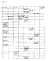
図17は、初めてNASをシステムに導入する際に、共有LUを初期化し、オペレーティングシステムをシステム用LUへインストールし、パーティションを作成するまでの手順を示している。図18は、CHNがフェイルオーバするときの手順を示している。図19は共有LUをバックアップし、共有LUが使用不能になった場合に共有LUバックアップの情報を用いてCHNがフェイルオーバするときの手順を示している。 FIG. 17 shows a procedure from initializing the shared LU to installing the operating system to the system LU and creating a partition when the NAS is first introduced into the system. FIG. 18 shows a procedure when CHN fails over. FIG. 19 shows a procedure when the shared LU is backed up and the CHN fails over using the shared LU backup information when the shared LU becomes unusable.
まず図17について説明する。図17の順番1から8までは、共有LUおよび共有LUバックアップをシステムとしてCHN1およびCHN5から認識できるようにするためのパス定義の手順である。次いで、図17の順番9から24までは、オペレーティングシステムをシステム用LUにインストールしながら、インストールソフトウェアによって共有LUおよび共有LUバックアップを初期化する手順を示している。
First, FIG. 17 will be described.
システム管理者または保守員は、管理端末160から論理レベルでの共有LUの初期化を指示する(図17-順番1)。これにより共有LUは、ディスクアレイとして論理的に初期化される(図17−順番2)。この状態では共有LUは、パスが定義されればI/Oプロセッサ119からは読み書きが可能な状態になっているが、オペレーティングシステムからの認識はまだできる状態にはなっていない。ついでシステム管理者または保守員は、管理端末160から論理レベルでの共有LUバックアップの初期化を指示する(図17−順番3)。これにより共有LUバックアップは、ディスクアレイとして論理的に初期化される(図17−順番4)。その後システム管理者または保守員は、管理端末160から共有LUへのパス定義指示を行う(図17−順番5)。これにより、CHN1およびCHN5と共有LUとが関連付けられ、CHN1およびCHN5に属するI/Oプロセッサ119は、共有LUに対してアクセスすることが可能となる(図17−順番6)。さらにシステム管理者または保守員は、管理端末160から共有LUバックアップへのパス定義指示を行う(図17−順番7)。これにより、CHN1およびCHN5に属するI/Oプロセッサ119は、共有LUバックアップに対してアクセスすることが可能となる(図17−順番8)。こののちシステム管理者は、オペレーティングシステムのインストール指示を行う。
The system administrator or maintenance staff instructs the
まずシステム管理者または保守員は、オペレーティングシステムをCHN1にインストールするよう、管理端末160から指示を発行する(図17−順番9)。これによりCHN1のオペレーティングシステムのインストールが開始される(図17−順番10)。インストールソフトウェアは、CPU112上にロードされた後動作を開始し、他にこれまでCHNが存在せず、当該インストール動作がシステムで初めてのものであることを検出すると、共有LUをオペレーティングシステムで使用可能となるようにオペレーティングシステムレベルでの初期化を行う(図17−順番11)。この初期化指示は実際にはI/Oプロセッサ119を通じて行われる。またこの際、クラスタ毎に共有LUの所定の部分を使用することを予めソフトウェア的に決定してある場合は、インストールソフトウェアは、各クラスタが使用すべき共有LUの所定領域を割り当てるために、共有LUの領域を分割する。この処理をパーティション作成という(図17−順番11)。これにより共有LUは、I/Oプロセッサからのみならず、オペレーティングシステムからのアクセスが可能なように初期化され、かつそれぞれのクラスタに属するオペレーティングシステムがそれぞれ独自の領域にアクセスができるようにパーティションに分割される(図17−順番12)。同様に、インストールソフトウェアは、共有LUバックアップについてもオペレーティングシステムレベルでの初期化指示、パーティション分割指示を行い(図17−順番13)、共有LUバックアップは各クラスタに属するオペレーティングシステムからアクセス可能なように初期化され、パーティションに分割される(図17−順番14)。
First, the system administrator or maintenance staff issues an instruction from the
インストールソフトウェアは、引き続いて共有LUの所定領域に、ファイルシステムを作成する(図17−順番15)。これはCHN1およびCHN5から共用されるものであるために、CHN1側で一旦作成されると、CHN5からは改めて作成する必要はない。この手順により共有LU上には、CHN1およびCHN5から、オペレーティングシステムがファイルシステムとしてアクセス可能な情報が作成される(図17−順番16)。同様に、インストールソフトウェアは、共有LUバックアップ上にファイルシステムを作成し(図17−順番17)、共有LUバックアップ上には、CHN1およびCHN5からオペレーティングシステムがファイルシステムとしてアクセス可能な情報が作成される(図17−順番18)。
Subsequently, the installation software creates a file system in a predetermined area of the shared LU (FIG. 17—order 15). Since this is shared by CHN1 and CHN5, once it is created on the CHN1 side, it is not necessary to create it again from CHN5. By this procedure, information that can be accessed by the operating system as a file system is created from the
その後インストールソフトウェアは、CHN1のオペレーティングシステムを格納するLU領域に対しオペレーティングシステムのインストールを行い、それが完了すると管理端末に対してCHN1へのオペレーティングシステムのインストールが完了したことを通知する(図17−順番19)。管理端末160ではこの完了通知を受領すると(図17−順番20)、終了したことを示すメッセージを端末画面に出力する。システム管理者または保守員は当該メッセージを確認したのち、こんどはCHN5に対して同様にオペレーティングシステムのインストール指示を行う(図17−順番21)。CHN5ではインストールソフトウェアが実行され、オペレーティングシステムのネットワークインストールが開始される(図17−順番22)。ただし、ここでは、既にCHN1がシステムにインストール済みであるため、共有LUや共有LUバックアップの初期化は行わない。インストールソフトウェアは、CHN5のオペレーティングシステムを格納するLU領域に対しオペレーティングシステムのインストールを行い、それが完了すると管理端末に対してCHN5へのオペレーティングシステムのインストールが完了したことを通知する(図17−順番23)。管理端末160ではこの完了通知を受領すると(図17−順番24)、終了したことを示すメッセージを端末画面に出力する。これによって、システムへのオペレーティングシステムのインストールと、共有LUおよび共有LUバックアップの初期化、パーティション作成が完了する。
After that, the installation software installs the operating system in the LU area storing the operating system of CHN1, and when this is completed, notifies the management terminal that the installation of the operating system in CHN1 is completed (FIG. 17-). Order 19). When the
なお、本実施例では、最初にオペレーティングシステムをインストールするCHN1上で動作するインストールソフトウェアが、他のCHNの使用するパーティションについてもすべて初期化を行ったが、そうではなくCHN1からはCHN1の使用する領域のみの初期化を行い、各CHN上でオペレーティングシステムをインストールするタイミングで、それぞれ関連する領域を初期化する方法としてもよい。またCHN毎の領域は、ある一つの共有LU内のパーティション毎に分ける形式にしたが、そうではなくCHN毎に共有LUを独自に割り当て、各共有LUに他のCHNからもパスを定義しアクセスが可能とすることで情報を共有する形式としてもよい。
In this embodiment, the installation software operating on the
次に、図18について説明する。 Next, FIG. 18 will be described.
図18は、CHN1のオペレーティングシステムが続行不能になった場合に、その業務をCHN5が引き継ぐ手順について述べている。
FIG. 18 describes a procedure in which
まず、本手順ではCHN5のオペレーティングシステムは、CHN1の障害発生(図18−順番10)までのいずれかの時点で動作していればよいが、本実施例では、説明を簡単にするため、CHN1での動作説明をする前の時点から動作しているものとして扱う(図18−順番1)。
First, in this procedure, the operating system of the
CHN1上で動作しているオペレーティングシステムは、CHN1から使用する共有LUのファイルシステムをマウントする(図18−順番2)。このファイルシステムは、例えば図17−順番15で作成したファイルシステムである。マウントが完了すると、オペレーティングシステムが当該ファイルシステムに対して、データの読み書きを行うことができるようになる(図18−順番3)。こののちオペレーティングシステムは通常のクライアントに対するファイルサービスなどの処理を開始する(図18−順番4)。 The operating system operating on CHN1 mounts the file system of the shared LU used from CHN1 (FIG. 18-order 2). This file system is, for example, the file system created in FIG. When the mounting is completed, the operating system can read / write data from / to the file system (FIG. 18—Sequence 3). After that, the operating system starts processing such as file service for a normal client (FIG. 18—order 4).
通常処理の間、CHN1のオペレーティングシステムは共有LUに対して、もしもCHN1が動作続行不能に陥った場合に、CHN5がクライアントに対するファイルサービスなどを肩代わりして再開できるような、引継ぎ情報を共有LUに書き込む(図18−順番5)。この書き込みは本実施例ではファイルシステムによる書き込みである。ファイルシステムを使用せず、たとえばブロックアクセスによって書き込む場合は、他のCHNからの書き込みと競合した場合の排他処理などを行う必要がある。また、引継ぎ情報は、クライアントのIPアドレスなどの情報、システム管理者や一般ユーザを含むユーザ情報、オペレーティングシステム上で動作しているサービスの動作情報、デーモンの動作情報など、あるいはユーザLUや共有LU、ファイルシステムをCHN1、CHNのどちらが使用しているかと行った情報、ファイルシステムがどのLUを使っているかと言う情報、CHN1やCHN5がクライアントに対して提供しているIPアドレスの情報などが含まれる。この引継ぎ情報の書き込みは、定期的あるいは必要情報に変更があった時点で、オペレーティングシステム自身の判断で共有LUに書き込まれる(図18−順番7、図18−順番9)。あるいは、管理端末160からの指示などによって、ユーザが共有LUに対して引継ぎ情報を書き込ませるようにしてもよい。
During normal processing, the operating system of CHN1 provides the shared LU with takeover information that allows CHN5 to resume the file service for the client if CHN1 fails to continue operation. Write (FIG. 18—Sequence 5). This writing is writing by the file system in this embodiment. For example, when writing is performed by block access without using the file system, it is necessary to perform exclusive processing when there is contention with writing from another CHN. The takeover information includes information such as the IP address of the client, user information including system administrators and general users, operation information of services operating on the operating system, operation information of daemons, and user LUs and shared LUs. , Information on which CHN1 or CHN is using the file system, information on which LU the file system is using, information on the IP address provided to the client by CHN1 or CHN5, etc. It is. This takeover information is written to the shared LU periodically or at a time when necessary information is changed (FIG. 18-
これとは別に、CHN5上で動作しているオペレーティングシステムは、CHN1が引き続き動作しているかどうかを定期的に監視している(図18−順番6、図18−順番8、図18−順番11)。
Apart from this, the operating system running on
ここでCHN1側に何らかの障害が発生し、クライアントへのサービスが中断した(図18−順番10)とする。このとき、CHN5上で動作しているオペレーティングシステムからの動作監視(図18−順番11)は、CHN1で障害が発生したことを検出する(図18−順番12)。すると、CHN5上で動作しているオペレーティングシステムは、共有LU上のファイルシステムを自らマウントする(図18−順番13)。マウントが完了する(図18−順番14)と、CHN5のオペレーティングシステムは、それまでCHN1のオペレーティングシステムが使用していた引継ぎ情報にアクセスすることが可能となる。CHN5のオペレーティングシステムは、この引継ぎ情報を用いて、クライアントに対して自らがあたかもCHN1であるかのごとく振るまい、サービスを再開することが可能となる(図18−順番15)。
Here, it is assumed that some trouble occurs on the CHN1 side, and the service to the client is interrupted (FIG. 18—order 10). At this time, the operation monitoring from the operating system operating on the CHN 5 (FIG. 18—sequence 11) detects that a failure has occurred in the CHN 1 (FIG. 18—sequence 12). Then, the operating system operating on the
なお、図18の実施例ではCHN1が通常処理系、CHN5が待機系という役割でフェイルオーバを行う例を挙げた。この例はいわゆるアクティブ−スタンバイと呼ばれる動作形式であるが、この他にも、CHN1とCHN5双方が通常処理系の、いわゆるアクティブ−アクティブの形態を取ることもできる。その場合は各CHN毎に個別のファイルシステムを作成し、CHNの障害時には互いに相手が使用しているファイルシステムをマウントすることとしてもよい。また共有LUへの情報格納はファイルシステム形式ではなく、論理アドレス形式にして、各CHN毎に予めデータ格納エリアを論理アドレス毎に割り当てておく方式としてもよい。アクティブ−アクティブ形式の場合は、図18で示したような引継ぎ情報の書き込みや、CHNの動作状態の監視を相互に行うこととなる。 In the embodiment of FIG. 18, an example is given in which failover is performed with the role of CHN1 being a normal processing system and CHN5 being a standby system. This example is a so-called active-standby operation type, but besides this, both CHN1 and CHN5 can take a so-called active-active form in which normal processing systems are used. In that case, a separate file system may be created for each CHN, and the file systems used by each other may be mounted when the CHN fails. Information storage in the shared LU may be performed in a logical address format instead of a file system format, and a data storage area is allocated in advance for each logical address for each CHN. In the case of the active-active format, writing of takeover information as shown in FIG. 18 and monitoring of the operation state of the CHN are mutually performed.
次に、図19について説明する。 Next, FIG. 19 will be described.
図19は共有LUをバックアップし、共有LUが使用不能になった場合に共有LUバックアップの情報を用いてCHNがフェイルオーバするときの手順を示している。 FIG. 19 shows a procedure when the shared LU is backed up and the CHN fails over using the shared LU backup information when the shared LU becomes unusable.
図18と同様、CHN1で障害が発生した場合に処理を引き継ぐ役割のCHN5については、当初から通常処理を開始しているものとする(図19−順番1)。また、図18と同様、本図の例はアクティブ−スタンバイの形式の例であるが、CHN1とCHN5の役割を入れ替え、双方が行うことにすればアクティブ−アクティブの形態として運用することも可能である。
Similarly to FIG. 18, it is assumed that the normal processing is started from the beginning for
CHN1上で動作しているオペレーティングシステムは、CHN1から使用する共有LUのファイルシステムをマウントする(図19−順番2)。このファイルシステムは、例えば図17−順番15で作成したファイルシステムである。マウントが完了すると、オペレーティングシステムが当該ファイルシステムに対して、データの読み書きを行うことができるようになる(図19−順番3)。こののちオペレーティングシステムは通常のクライアントに対するファイルサービスなどの処理を開始する(図19−順番4)。 The operating system operating on CHN1 mounts the file system of the shared LU used from CHN1 (FIG. 19-order 2). This file system is, for example, the file system created in FIG. When the mounting is completed, the operating system can read / write data from / to the file system (FIG. 19—Sequence 3). After that, the operating system starts processing such as a file service for a normal client (FIG. 19—order 4).
通常処理の間、CHN1のオペレーティングシステムは共有LUに対して、もしもCHN1が動作続行不能に陥った場合に、CHN5がクライアントに対するファイルサービスなどを肩代わりして再開できるような、引継ぎ情報を共有LUに書き込む(図19−順番5)。この書き込みは本実施例ではファイルシステムによる書き込みである。ファイルシステムを使用せず、たとえばブロックアクセスによって書き込む場合は、他のCHNからの書き込みと競合した場合の排他処理などを行う必要がある。また、引継ぎ情報は、クライアントのIPアドレスなどの情報、システム管理者や一般ユーザを含むユーザ情報、オペレーティングシステム上で動作しているサービスの動作情報、デーモンの動作情報など、あるいはユーザLUや共有LU、ファイルシステムをCHN1、CHNのどちらが使用しているかと行った情報、ファイルシステムがどのLUを使っているかと言う情報、CHN1やCHN5がクライアントに対して提供しているIPアドレスの情報などが含まれる。この引継ぎ情報の書き込みは、定期的あるいは必要情報に変更があった時点で、オペレーティングシステム自身の判断で共有LUに書き込まれる(図19−順番7)。あるいは、管理端末160からの指示などによって、ユーザが共有LUに対して引継ぎ情報を書き込ませるようにしてもよい。
During normal processing, the operating system of CHN1 provides the shared LU with takeover information that allows CHN5 to resume the file service for the client if CHN1 fails to continue operation. Write (FIG. 19—Sequence 5). This writing is writing by the file system in this embodiment. For example, when writing is performed by block access without using the file system, it is necessary to perform exclusive processing when there is contention with writing from another CHN. The takeover information includes information such as the IP address of the client, user information including system administrators and general users, operation information of services operating on the operating system, operation information of daemons, and user LUs and shared LUs. , Information on which CHN1 or CHN is using the file system, information on which LU the file system is using, information on the IP address provided to the client by CHN1 or CHN5, etc. It is. The takeover information is written to the shared LU at the discretion of the operating system itself periodically or when necessary information is changed (FIG. 19—Sequence 7). Alternatively, the user may cause the takeover information to be written to the shared LU according to an instruction from the
これとは別に、CHN5上で動作しているオペレーティングシステムは、CHN1が引き続き動作しているかどうかを定期的に監視している(図19−順番6、図19−順番16)。
Apart from this, the operating system operating on the
CHN1のオペレーティングシステムからはいつでも、OSのコピーコマンドにより、CHN1およびCHN5で使用する共有LUの領域をバックアップすることができる(図19−順番8)。これは例えば、LAN400上の情報処理装置200上で動作するUNIXオペレーティングシステム714や、Windowsオペレーティングシステム715から、CPU112上で動作しているオペレーティングシステム702にログインし、オペレーティングシステム702が汎用に提供しているコピーコマンドを使用してもよい。オペレーティングシステム702がUNIXである場合には、たとえばこのコマンドはcpというコマンドとなる。ファイルシステムを使用せず、LUデバイスを指定して直接データをブロック単位でコピーする場合には、このコマンドは例えばddというコマンドとなる。また、LAN400上の情報処理装置200上で動作するUNIXオペレーティングシステム714や、Windowsオペレーティングシステム715から、CPU112上で動作しているNASマネージャ等のアプリケーション706にログインし、アプリケーションの機能を用いてコピーしてもよい。あるいは管理端末160からこれらオペレーティングシステムやアプリケーションにログインしてコピー機能を実行してもよいし、管理端末160からディスク制御部140に指示を発行することにより、ディスク制御部が独自にコピーをおこなってもよい。更に、I/Oプロセッサ119上のコントローラマイクロプログラム、CPU112上のNASマネージャ等のアプリケーション、CPU112上のオペレーティングシステム、ディスク制御部140上のRAID制御部740やCPU142がシステム状態を監視し、たとえばシステムに対するデータ転送負荷の割合が一定値より低く、コピーを実行したとしてもクライアントに対するサービスに性能低下などの著しい悪影響を及ぼさないと判断した時点で、自動的にこれらのコマンドを起動および実行させ、バックアップを行うようにしてもよい。
From the operating system of the
本実施例では、オペレーティングシステムが汎用に提供しているcpコマンドを情報処理端末200からログインして使うものとする。これにより、共有LU上のCHN1およびCHN5用の領域は共有LUバックアップの対応する領域にコピーされる(図19−順番9、図19−順番10)。
In this embodiment, it is assumed that the cp command provided by the operating system for general use is logged in from the
また、バックアップを同一ディスクアレイ装置内の共有LUバックアップ321乃至324に対してではなく、外部バックアップデバイス900や、外部記憶装置システム610に対して作成してもよい。ここでは、NDMP(Network Data Management Protocol)を用いて、SAN経由でテープデバイス900に対して、CHN1およびCHN5用の共有LU領域をバックアップする方法を示す(図19−順番11)。これによりデータは外部バックアップデバイスにバックアップされる(図19−順番12、図19−順番13)。なお、外部記憶装置システム610に対して共有LUをバックアップした場合、その情報を用いて外部記憶装置システム610においてクライアントに対するサービスを引き継ぐことも考えられる。この場合はクライアントに対するサービスのみならず、クライアントがアクセスしていたユーザデータそのものもリモートコピー機能などを用いて外部記憶装置システム610に同期しておく必要がある。
Further, the backup may be created not for the shared
ここで、共有LUが障害などにより使用不能になったとする(図19−順番14)。この時点では、特にクライアントに対するファイルサービスに影響は発生しないが、ここで更にCHN1が何らかの障害が発生し(図19−順番15)、フェイルオーバが必要になった場合に、図18−順番13のようなCHN5からの引継ぎ情報の取得が不可能となる。実際には、CHN5上のオペレーティングシステムはCHN1の障害発生を検出すると(図19−順番17)、共有LUのファイルシステムのマウント指示を行う(図19−順番18)が、このマウント操作は共有LUが使用不能であるため失敗する(図19−順番19)。この共有LUのマウント失敗を検出すると、CHN5のオペレーティングシステムは、共有LUのバックアップにあるファイルシステムをマウントするように指示する(図19−順番20)。これにより共有LUのバックアップにあるファイルシステムに対して、CHN5のオペレーティングシステムが読み書きを行うことができるようになる(図19−順番21)。その後、CHN5のオペレーティングシステムは、共有LUのバックアップの引継ぎ情報を元に、クライアントに対してCHN1のファイルサービスなどの業務を再開することが可能となる(図19−順番22)。
Here, it is assumed that the shared LU becomes unusable due to a failure or the like (FIG. 19—order 14). At this point, there is no particular effect on the file service for the client. However, when a failure occurs further in CHN1 (FIG. 19-order 15) and a failover is necessary, as shown in FIG. 18-
この後、例えば物理的なデバイスの交換などによって共有LUが再び使用可能となった場合は、デバイス交換の契機などによって共有LUを再び初期化し、図19−順番8などの手順を共有LUのバックアップから共有LUに対して実行することにより、再度共有LUに引継ぎ情報を書き戻すこともできる。 Thereafter, for example, when the shared LU becomes usable again due to physical device replacement or the like, the shared LU is reinitialized at the time of device replacement or the like, and the procedure shown in FIG. , The takeover information can be written back to the shared LU again.
以上本実施の形態について説明したが、上記実施の形態は本発明の理解を容易にするためのものであり、本発明を限定して解釈するためのものではない。本発明はその趣旨を逸脱することなく変更、改良され得るとともに、本発明にはその等価物等も含まれる。 Although the present embodiment has been described above, the above embodiment is intended to facilitate understanding of the present invention and is not intended to limit the present invention. The present invention can be changed and improved without departing from the gist thereof, and the present invention includes equivalents thereof.
100 記憶デバイス制御装置
110 チャネル制御部
111 ネットワークインタフェース部
112 CPU
113 メモリ
114 入出力制御部
115 NVRAM
116 ボード接続用コネクタ
117 通信コネクタ
118 回路基板
119 I/Oプロセッサ
120 共有メモリ
130 キャッシュメモリ
140 ディスク制御部
150 接続部
151 内部LAN
160 管理端末
600 記憶装置システム
801 BIOS
802 通信メモリ
803 ハードウェアレジスタ群
804 NVRAM
100
113
116
160
802
Claims (20)
前記複数の記憶デバイスに対するデータの格納を制御する記憶デバイス制御部と、
前記記憶デバイス制御部に接続される接続部と、
前記接続部及び自ディスクアレイ装置の外部のローカルエリアネットワークに接続される複数の第一のチャネル制御部と、
前記複数の第一のチャネル制御部及び前記記憶デバイス制御部によってやり取りされる制御情報が格納される共有メモリと、
前記複数の第一のチャネル制御部と前記記憶デバイス制御部との間でやり取りされるデータを一時的に保存するキャッシュメモリと
を備え、
前記第一のチャネル制御部は、
前記ローカルエリアネットワークを介して受けたファイルレベルのデータをブロックレベルのデータに変換して、前記複数の記憶デバイスへの格納を要求する第一のプロセッサと、
前記第一のプロセッサからの要求に応じて前記接続部及び前記記憶デバイス制御部を介して前記複数の記憶デバイスに前記ブロックレベルのデータを転送する第二のプロセッサと
を備え、
前記第二のプロセッサは、
前記ブロックレベルのデータが格納される複数の記憶領域と、複数の前記第一のプロセッサによって相互にやり取りされるプロセッサ間の処理状況に関する情報が格納されるプロセッサ情報格納領域とを前記複数の記憶デバイスの記憶領域を用いて作成するものであり、
前記記憶デバイス制御部は、
前記第一のプロセッサの指示に応じて、前記プロセッサ情報格納領域に格納された情報を、前記複数の記憶デバイスの記憶領域を用いて作成されたプロセッサ情報バックアップ用の格納領域に対してコピーするものであり、
前記プロセッサ情報格納領域は、複数の第一のパーティションに分割され、
各前記第一のパーティションは、
それぞれ当該第一のパーティションと対応付けられた第一のチャネル制御部と、当該第一のチャネル制御部に障害が発生した場合に当該第一のチャネル制御部の処理を引き継ぐ他の第一のチャネル制御部と、からのアクセスが可能に設定され、
前記プロセッサ情報バックアップ用の格納領域は、複数の第二のパーティションに分割され、
前記第二のパーティションは、
当該第二のパーティションと対応付けられた前記第一のパーティションに対するアクセスが可能に設定された前記第一のチャネル制御部と、当該第一のチャネル制御部に障害が発生した場合に当該第一のチャネル制御部の処理を引き継ぐ前記他の第一のチャネル制御部と、からのアクセスが可能に設定され、
前記記憶デバイス制御部は、
前記第一のパーティションに格納された情報を、当該第一のパーティションと対応付けられた前記第二のパーティションにコピーする
ことを特徴とするディスクアレイ装置。 A plurality of storage devices for storing data;
A storage device controller that controls storage of data in the plurality of storage devices;
A connection unit connected to the storage device control unit;
A plurality of first channel controllers connected to a local area network outside the connection unit and the own disk array device;
A shared memory storing control information exchanged by the plurality of first channel control units and the storage device control unit;
A cache memory for temporarily storing data exchanged between the plurality of first channel control units and the storage device control unit,
The first channel controller is
A first processor that converts file level data received via the local area network into block level data and requests storage to the plurality of storage devices;
A second processor for transferring the block level data to the plurality of storage devices via the connection unit and the storage device control unit in response to a request from the first processor,
The second processor is
The plurality of storage devices including a plurality of storage areas in which the block-level data is stored and a processor information storage area in which information on a processing state between processors exchanged by the plurality of first processors is stored. It is created using the storage area of
The storage device controller
Copying information stored in the processor information storage area to a processor information backup storage area created using the storage areas of the plurality of storage devices in response to an instruction from the first processor der is,
The processor information storage area is divided into a plurality of first partitions;
Each said first partition is
A first channel control unit associated with the first partition and another first channel that takes over the processing of the first channel control unit when a failure occurs in the first channel control unit. Access from the control unit is set to be possible,
The storage area for processor information backup is divided into a plurality of second partitions,
The second partition is
The first channel control unit that is set to be accessible to the first partition associated with the second partition and the first channel control unit when a failure occurs in the first channel control unit Access from the other first channel control unit taking over the processing of the channel control unit is set to be possible,
The storage device controller
A disk array device , wherein information stored in the first partition is copied to the second partition associated with the first partition .
前記第一のプロセッサは、
前記第一のプロセッサが設けられている前記第一のチャネル制御部内の前記第二のプロセッサに対して、前記第一のプロセッサの処理状況に関する情報を前記プロセッサ情報格納領域に格納するように指示するものであり、
前記第二のプロセッサは、
前記第一のプロセッサの指示に応じて、前記第一のプロセッサの処理状況に関する情報を、前記プロセッサ情報格納領域内の対応する前記第一のパーティションに格納するものである
ことを特徴とするディスクアレイ装置。 The disk array device according to claim 1,
The first processor is
Instructs the second processor in the first channel control unit provided with the first processor to store information on the processing status of the first processor in the processor information storage area. Is,
The second processor is
In accordance with an instruction from the first processor, information relating to the processing status of the first processor is stored in the corresponding first partition in the processor information storage area . apparatus.
前記第二のプロセッサは、
前記第二のプロセッサが設けられている前記第一のチャネル制御部内の前記第一のプロセッサの要求に従って、前記ブロックレベルのデータを前記キャッシュメモリに保存するとともに、前記ブロックレベルのデータを前記キャッシュメモリに保存したことを表す情報を前記共有メモリに格納するものであり、
前記共有メモリは、
前記第二のプロセッサの制御のもとに、前記ブロックレベルのデータが前記キャッシュメモリに保存されたことを表す情報が格納されるものである
ことを特徴とするディスクアレイ装置。 The disk array device according to claim 1,
The second processor is
The block level data is stored in the cache memory according to a request of the first processor in the first channel control unit provided with the second processor, and the block level data is stored in the cache memory. Storing information in the shared memory indicating that it is stored in
The shared memory is
A disk array device, wherein information indicating that the block level data is stored in the cache memory is stored under the control of the second processor.
前記第一のプロセッサは、
前記記憶デバイス制御部に対して、前記プロセッサ情報格納領域内の前記第一のパーティションに格納された情報を、前記プロセッサ情報バックアップ用の格納領域内の対応する前記第二のパーティションに対してコピーするように指示するものであり、
前記記憶デバイス制御部は、
前記第一のプロセッサの指示に応じて、コピーするものである
ことを特徴とするディスクアレイ装置。 The disk array device according to claim 1,
The first processor is
The information stored in the first partition in the processor information storage area is copied to the corresponding second partition in the storage area for processor information backup to the storage device controller. Is to instruct
The storage device controller
A disk array device that performs copying in accordance with an instruction from the first processor.
前記第一のプロセッサは、
前記プロセッサ情報格納領域内の対応する前記第一のパーティションに格納された情報の読み出し又は書き込みが不可能になった場合、前記プロセッサ情報バックアップ用の格納領域内の対応する前記第二のパーティションに格納された情報を読み出し又は書き込むことにより、処理を継続する
ことを特徴とするディスクアレイ装置。 The disk array device according to claim 4,
The first processor is
When reading or writing of information stored in the corresponding first partition in the processor information storage area becomes impossible, the information is stored in the corresponding second partition in the processor information backup storage area . The disk array device is characterized in that the processing is continued by reading or writing the read information.
前記複数の第一のチャネル制御部は、
複数のクラスタグループに分類されるものであり、
前記複数のクラスタグループは、
前記複数の第一のパーティションのうちの各々異なる第一のパーティションを割当てられるものである
ことを特徴とするディスクアレイ装置。 The disk array device according to claim 1,
The plurality of first channel controllers are
Are classified into multiple cluster groups,
The plurality of cluster groups are:
The disk array apparatus, characterized in that assigned to each different first partition of the plurality of first partition.
前記複数のクラスタグループのうちの第一のクラスタグループに含まれる前記複数の第一のチャネル制御部は、
対応する第一のパーティションに対して、前記第一のプロセッサによって相互にやり取りされるプロセッサ間の処理状況に関する情報を格納するものであり、
前記複数のクラスタグループのうちの第二のクラスタグループに含まれる前記複数の第一のチャネル制御部は、
対応する他の第一のパーティションに対して、前記第一のプロセッサによって相互にやり取りされるプロセッサ間の処理状況に関する情報を格納するものである
ことを特徴とするディスクアレイ装置。 The disk array device according to claim 6,
The plurality of first channel control units included in a first cluster group of the plurality of cluster groups,
For the corresponding first partition , information related to the processing status between the processors exchanged by the first processor is stored.
The plurality of first channel control units included in a second cluster group of the plurality of cluster groups,
A disk array device, which stores information related to the processing status between processors exchanged by the first processor with respect to another corresponding first partition .
前記第一のクラスタグループに含まれる前記複数の第一のチャネル制御部の前記第一のプロセッサは、
前記第一のパーティションに格納された情報の複製の作成を、前記記憶デバイス制御部に対して指示するものであり、
前記記憶デバイス制御部は、
前記第一のクラスタグループに含まれる前記複数の第一のチャネル制御部の前記第一のプロセッサの指示に応じて、対応する前記第二のパーティションに対して、前記第一のパーティションに格納された情報の複製を格納するものである
ことを特徴とするディスクアレイ装置。 The disk array device according to claim 7,
The first processors of the plurality of first channel control units included in the first cluster group are:
Instructing the storage device controller to create a copy of the information stored in the first partition ,
The storage device controller
In response to an instruction from the first processor of the plurality of first channel control units included in the first cluster group, the corresponding second partition is stored in the first partition . A disk array device that stores a copy of information.
前記第一のクラスタグループに含まれる前記複数の第一のチャネル制御部の前記第一のプロセッサは、
前記第一のパーティション及び前記他の第一のパーティションに格納された情報の複製の作成を、前記記憶デバイス制御部に対して指示するものであり、
前記記憶デバイス制御部は、
前記第一のクラスタグループに含まれる前記複数の第一のチャネル制御部の前記第一のプロセッサの指示に応じて、前記プロセッサ情報バックアップ用の格納領域内の前記第一のパーティションに対応する第二のパーティションに対して、当該第一のパーティションに格納された情報の複製を格納し、前記プロセッサ情報バックアップ用の格納領域内の前記他の第一のパーティションに対応する第二のパーティションに対して、当該他の第一のパーティションに格納された情報の複製を格納するものである
ことを特徴とするディスクアレイ装置。 The disk array device according to claim 7,
The first processors of the plurality of first channel control units included in the first cluster group are:
Instructing the storage device controller to create a copy of the information stored in the first partition and the other first partition ,
The storage device controller
The second corresponding to the first partition in the processor information backup storage area according to the instruction of the first processor of the plurality of first channel control units included in the first cluster group For the second partition , store a copy of the information stored in the first partition, and for the second partition corresponding to the other first partition in the storage area for the processor information backup, A disk array device for storing a copy of information stored in the other first partition .
前記複数の第一のチャネル制御部及び前記記憶デバイス制御部に関する情報の取得に利用される管理端末を備え、
前記記憶デバイス制御部は、
前記管理端末からの指示に応じて、前記プロセッサ情報バックアップ用の格納領域内の前記第一のパーティションに対応する第二のパーティションに対して、当該第一のパーティションに格納された情報の複製を格納し、前記プロセッサ情報バックアップ用の格納領域内の前記他の第一のパーティションに対応する第二のパーティションに対して、当該他の第一のパーティションに格納された情報の複製を格納するものである
ことを特徴とするディスクアレイ装置。 The disk array device according to claim 7,
A management terminal used to obtain information about the plurality of first channel control units and the storage device control unit;
The storage device controller
In response to an instruction from the management terminal, a copy of the information stored in the first partition is stored in the second partition corresponding to the first partition in the processor information backup storage area . In addition, a copy of the information stored in the other first partition is stored in the second partition corresponding to the other first partition in the storage area for processor information backup. A disk array device characterized by that.
前記第一のクラスタグループに含まれる前記複数の第一のチャネル制御部の前記第一のプロセッサは、
対応する前記第一のパーティションに格納された情報の読み出し又は書き込みが不可能になった場合、対応する第二のパーティションに格納された情報を読み出し又は書き込むことにより、処理を継続するものである
ことを特徴とするディスクアレイ装置。 The disk array device according to claim 8, wherein
The first processors of the plurality of first channel control units included in the first cluster group are:
When reading or writing of information stored in the corresponding first partition becomes impossible, processing is continued by reading or writing information stored in the corresponding second partition. A disk array device characterized by the above.
前記複数の記憶デバイスに対するデータの格納を制御する記憶デバイス制御部と、
前記記憶デバイス制御部に接続される接続部と、
自ディスクアレイ装置の外部のローカルエリアネットワークを介して受けたファイルレベルのデータをブロックレベルのデータに変換して、前記複数の記憶デバイスへの格納を要求する第一のプロセッサと、前記第一のプロセッサからの要求に応じて前記接続部及び前記記憶デバイス制御部を介して前記複数の記憶デバイスに前記ブロックレベルのデータを転送する第二のプロセッサとを有し、前記接続部及び前記ローカルエリアネットワークに接続される複数の第一のチャネル制御部と、
前記複数の第一のチャネル制御部及び前記記憶デバイス制御部によってやり取りされる制御情報が格納される共有メモリと、
前記複数の第一のチャネル制御部と前記記憶デバイス制御部との間でやり取りされるデータを一時的に保存するキャッシュメモリと
を備え、
前記第二のプロセッサは、
前記ブロックレベルのデータが格納される複数の記憶領域と、複数の前記第一のプロセッサによって相互にやり取りされるプロセッサ間の処理状況に関する情報が格納されるプロセッサ情報格納領域と、複数の前記第一のプロセッサ上で動作するソフトウェアプログラムが格納されるソフトウェアプログラム格納領域とを前記複数の記憶デバイスの記憶領域を用いて作成するものであり、
前記第一のプロセッサは、
前記第一のプロセッサが設けられている前記第一のチャネル制御部内の前記第二のプロセッサの制御に応じて、前記ソフトウェアプログラム格納領域に格納されているソフトウェアプログラムを取得して、前記ソフトウェアプログラムに基づいて処理を実行するものであり、
前記記憶デバイス制御部は、
前記第一のプロセッサの指示に応じて、前記プロセッサ情報格納領域に格納された情報を、前記複数の記憶デバイスの記憶領域を用いて作成されたプロセッサ情報バックアップ用の格納領域に対してコピーするものであり、
前記プロセッサ情報格納領域は、複数の第一のパーティションに分割され、
各前記第一のパーティションは、
それぞれ当該第一のパーティションと対応付けられた第一のチャネル制御部と、当該第一のチャネル制御部に障害が発生した場合に当該第一のチャネル制御部の処理を引き継ぐ他の第一のチャネル制御部と、からのアクセスが可能に設定され、
前記プロセッサ情報バックアップ用の格納領域は、複数の第二のパーティションに分割され、
前記第二のパーティションは、
当該第二のパーティションと対応付けられた前記第一のパーティションに対するアクセスが可能に設定された前記第一のチャネル制御部と、当該第一のチャネル制御部に障害が発生した場合に当該第一のチャネル制御部の処理を引き継ぐ前記他の第一のチャネル制御部と、からのアクセスが可能に設定され、
前記記憶デバイス制御部は、
前記第一のパーティションに格納された情報を、当該第一のパーティションと対応付けられた前記第二のパーティションにコピーする
ことを特徴とするディスクアレイ装置。 A plurality of storage devices for storing data;
A storage device controller that controls storage of data in the plurality of storage devices;
A connection unit connected to the storage device control unit;
A first processor that converts file level data received via a local area network outside the own disk array device into block level data and requests storage in the plurality of storage devices; A second processor for transferring the block level data to the plurality of storage devices via the connection unit and the storage device control unit in response to a request from the processor, and the connection unit and the local area network A plurality of first channel controllers connected to
A shared memory storing control information exchanged by the plurality of first channel control units and the storage device control unit;
A cache memory for temporarily storing data exchanged between the plurality of first channel control units and the storage device control unit,
The second processor is
A plurality of storage areas in which the block level data is stored; a processor information storage area in which information on a processing status between processors exchanged by the plurality of first processors is stored; A software program storage area in which a software program operating on the processor is stored using the storage areas of the plurality of storage devices,
The first processor is
In response to the control of the second processor in the first channel control unit in which the first processor is provided, the software program stored in the software program storage area is acquired, and the software program is stored in the software program. all SANYO executing the processing based,
The storage device controller
Copying information stored in the processor information storage area to a processor information backup storage area created using the storage areas of the plurality of storage devices in response to an instruction from the first processor And
The processor information storage area is divided into a plurality of first partitions;
Each said first partition is
A first channel control unit associated with the first partition and another first channel that takes over the processing of the first channel control unit when a failure occurs in the first channel control unit. Access from the control unit is set to be possible,
The storage area for processor information backup is divided into a plurality of second partitions,
The second partition is
The first channel control unit that is set to be accessible to the first partition associated with the second partition and the first channel control unit when a failure occurs in the first channel control unit Access from the other first channel control unit taking over the processing of the channel control unit is set to be possible,
The storage device controller
A disk array device , wherein information stored in the first partition is copied to the second partition associated with the first partition .
前記複数の第一のチャネル制御部内の前記第一のプロセッサは、
前記ソフトウェアプログラムに基づいて、前記記憶デバイス制御部に対して、前記プロセッサ情報格納領域に格納された情報を、前記プロセッサ情報バックアップ用の格納領域に対してコピーするように指示するものであり、
前記記憶デバイス制御部は、
前記複数の第一のチャネル制御部内の前記第一のプロセッサの指示に応じて、前記プロセッサ情報格納領域内の対応する前記第一のパーティションに格納された情報を、前記複数の記憶デバイスの記憶領域を用いて作成されたプロセッサ情報バックアップ用の格納領域内の対応する前記第二のパーティションに対してコピーするものである
ことを特徴とするディスクアレイ装置。 The disk array device according to claim 12, wherein
The first processor in the plurality of first channel controllers is:
Based on the software program, the storage device control unit is instructed to copy the information stored in the processor information storage area to the processor information backup storage area,
The storage device controller
In response to an instruction from the first processor in the plurality of first channel control units, information stored in the corresponding first partition in the processor information storage area is stored in the storage area of the plurality of storage devices. A disk array device that copies to the corresponding second partition in the storage area for processor information backup created by using the disk array device.
前記複数の第一のチャネル制御部は、
複数のクラスタグループに分類されるものであり、
前記複数のクラスタグループのうちの第一のクラスタグループに含まれる前記複数の第一のチャネル制御部は、
各々の前記ソフトウェアプログラムに基づいて、相互に、対応する前記第一のパーティションに対して、プロセッサ間の処理状況に関する情報を格納するものである
ことを特徴とするディスクアレイ装置。 The disk array device according to claim 12, wherein
The plurality of first channel controllers are
Are classified into multiple cluster groups,
The plurality of first channel control units included in a first cluster group of the plurality of cluster groups,
A disk array device that stores information on the processing status between processors for each of the corresponding first partitions based on the software programs.
前記複数の第一のチャネル制御部は、
複数のクラスタグループに分類されるものであり、
前記複数の第一のパーティションに格納された情報は、
前記複数のクラスタグループ毎に、それぞれ対応する前記第二のパーティションに複製されるものである
ことを特徴とするディスクアレイ装置。 The disk array device according to claim 12, wherein
The plurality of first channel controllers are
Are classified into multiple cluster groups,
Information stored in the plurality of first partition,
The disk array device, wherein each of the plurality of cluster groups is replicated to the corresponding second partition .
前記複数のクラスタグループのうちの第一のクラスタグループに含まれる前記複数の第一のチャネル制御部内の前記第一のプロセッサは、
前記第一のプロセッサが設けられている前記第一のチャネル制御部内の前記第二のプロセッサを介して、前記記憶デバイス制御部に対して、ブロック単位で前記複製を実行するように指示するものであり、
前記記憶デバイス制御部は、
前記第一のプロセッサの指示に応じて、対応する前記第一のパーティションに格納された情報を、ブロック単位で、対応する前記第二のパーティションに複製するものである
ことを特徴とするディスクアレイ装置。 The disk array device according to claim 15, wherein
The first processor in the plurality of first channel control units included in the first cluster group of the plurality of cluster groups,
Instructs the storage device control unit to execute the duplication in block units via the second processor in the first channel control unit in which the first processor is provided. Yes,
The storage device controller
In response to an instruction of said first processor, corresponding to the information stored in the first partition, in blocks corresponding disk array apparatus, characterized in that to duplicate the second partition .
前記ローカルエリアネットワークには、端末が設けられており、
前記複数のクラスタグループのうちの第一のクラスタグループに含まれる前記複数の第一のチャネル制御部内の前記第一のプロセッサは、
前記端末からの指示に応じて、前記第一のプロセッサが設けられている前記第一のチャネル制御部内の前記第二のプロセッサを介して、前記記憶デバイス制御部に対して、ブロック単位で前記複製を実行するように指示するものである
ことを特徴とするディスクアレイ装置。 The disk array device according to claim 15, wherein
The local area network is provided with a terminal,
The first processor in the plurality of first channel control units included in the first cluster group of the plurality of cluster groups,
In response to an instruction from the terminal, the replication is performed in block units with respect to the storage device control unit via the second processor in the first channel control unit in which the first processor is provided. A disk array device characterized by instructing to execute
前記複数のクラスタグループのうちの第一のクラスタグループに含まれる前記複数の第一のチャネル制御部内の前記第一のプロセッサは、
一定の時間間隔毎に、前記第一のプロセッサが設けられている前記第一のチャネル制御部内の前記第二のプロセッサを介して、前記記憶デバイス制御部に対して、ブロック単位で前記複製を実行するように指示するものである
ことを特徴とするディスクアレイ装置。 The disk array device according to claim 15, wherein
The first processor in the plurality of first channel control units included in the first cluster group of the plurality of cluster groups,
The replication is executed in block units for the storage device controller via the second processor in the first channel controller provided with the first processor at regular time intervals. A disk array device, characterized by:
前記複数のクラスタグループのうちの第一のクラスタグループに含まれる前記複数の第一のチャネル制御部内の前記第一のプロセッサは、
前記第一のプロセッサが設けられている前記第一のチャネル制御部内の前記第二のプロセッサを介して、前記記憶デバイス制御部の負荷状態を取得し、前記記憶デバイス制御部の負荷状態に応じて、前記記憶デバイス制御部に対して、ブロック単位で前記複製を実行するように指示するものである
ことを特徴とするディスクアレイ装置。 The disk array device according to claim 15, wherein
The first processor in the plurality of first channel control units included in the first cluster group of the plurality of cluster groups,
Via the second processor in the first channel control unit in which the first processor is provided, the load state of the storage device control unit is obtained, and according to the load state of the storage device control unit The disk array device is configured to instruct the storage device control unit to execute the replication in block units.
前記複数のクラスタグループのうちの第一のクラスタグループに含まれる前記複数の第一のチャネル制御部内の前記第一のプロセッサは、
対応する前記第一のパーティションに格納された情報へのアクセスが不可能になった場合に、対応する前記第二のパーティションに格納された情報を用いて処理を実行し、前記第一のパーティションが新たに形成された場合に、前記第二のパーティションに格納された情報を前記新たに形成された第一のパーティションに複製して、前記新たに形成された第一のパーティションに格納された情報を用いて、処理を実行するものである
ことを特徴とするディスクアレイ装置。 The disk array device according to claim 15, wherein
The first processor in the plurality of first channel control units included in the first cluster group of the plurality of cluster groups,
When access to the information stored in the corresponding first partition becomes impossible, processing is performed using the information stored in the corresponding second partition, and the first partition When newly formed, the information stored in the second partition is copied to the newly formed first partition , and the information stored in the newly formed first partition is A disk array device characterized by being used to execute processing.
Priority Applications (8)
| Application Number | Priority Date | Filing Date | Title |
|---|---|---|---|
| JP2003394922A JP4400913B2 (en) | 2003-11-26 | 2003-11-26 | Disk array device |
| US10/806,128 US7043604B2 (en) | 2003-11-26 | 2004-03-23 | Disk array system |
| DE102004027672A DE102004027672A1 (en) | 2003-11-26 | 2004-06-07 | Disk array system |
| GB0414191A GB2408817B (en) | 2003-11-26 | 2004-06-24 | Disk array system |
| FR0406968A FR2866732A1 (en) | 2003-11-26 | 2004-06-25 | DISC NETWORK SYSTEM |
| US11/046,719 US7099996B2 (en) | 2003-11-26 | 2005-02-01 | Disk array system |
| US11/448,733 US7376787B2 (en) | 2003-11-26 | 2006-06-08 | Disk array system |
| US12/003,597 US7581062B2 (en) | 2003-11-26 | 2007-12-28 | Disk array system |
Applications Claiming Priority (1)
| Application Number | Priority Date | Filing Date | Title |
|---|---|---|---|
| JP2003394922A JP4400913B2 (en) | 2003-11-26 | 2003-11-26 | Disk array device |
Publications (3)
| Publication Number | Publication Date |
|---|---|
| JP2005157713A JP2005157713A (en) | 2005-06-16 |
| JP2005157713A5 JP2005157713A5 (en) | 2006-12-14 |
| JP4400913B2 true JP4400913B2 (en) | 2010-01-20 |
Family
ID=32821789
Family Applications (1)
| Application Number | Title | Priority Date | Filing Date |
|---|---|---|---|
| JP2003394922A Expired - Fee Related JP4400913B2 (en) | 2003-11-26 | 2003-11-26 | Disk array device |
Country Status (5)
| Country | Link |
|---|---|
| US (4) | US7043604B2 (en) |
| JP (1) | JP4400913B2 (en) |
| DE (1) | DE102004027672A1 (en) |
| FR (1) | FR2866732A1 (en) |
| GB (1) | GB2408817B (en) |
Families Citing this family (50)
| Publication number | Priority date | Publication date | Assignee | Title |
|---|---|---|---|---|
| JP2004280283A (en) * | 2003-03-13 | 2004-10-07 | Hitachi Ltd | Distributed file system, distributed file system server, and access method to distributed file system |
| JP4320195B2 (en) | 2003-03-19 | 2009-08-26 | 株式会社日立製作所 | File storage service system, file management apparatus, file management method, ID designation type NAS server, and file reading method |
| JP4400913B2 (en) * | 2003-11-26 | 2010-01-20 | 株式会社日立製作所 | Disk array device |
| US20050251617A1 (en) * | 2004-05-07 | 2005-11-10 | Sinclair Alan W | Hybrid non-volatile memory system |
| JP2005250938A (en) * | 2004-03-05 | 2005-09-15 | Hitachi Ltd | Storage control system and method |
| JP2005267111A (en) * | 2004-03-17 | 2005-09-29 | Hitachi Ltd | Storage control system and method for controlling storage control system |
| JP2005301708A (en) * | 2004-04-13 | 2005-10-27 | Hitachi Ltd | Storage device system and software management method in same system |
| JP2006011541A (en) | 2004-06-22 | 2006-01-12 | Hitachi Ltd | Information recording method in computer system including computer and shared storage device |
| US7716315B2 (en) * | 2004-09-24 | 2010-05-11 | Emc Corporation | Enclosure configurable to perform in-band or out-of-band enclosure management |
| JP4987307B2 (en) * | 2005-03-25 | 2012-07-25 | 株式会社日立製作所 | Storage system |
| US7640415B2 (en) * | 2005-03-25 | 2009-12-29 | Hitachi, Ltd. | Storage system having a first computer, a second computer connected to the first computer via a network, and a storage device system that is accessed by the second computer |
| US8873574B2 (en) | 2005-07-25 | 2014-10-28 | Hewlett-Packard Development Company, L.P. | Network-attached storage device having a connection to a local user device |
| US20070061227A1 (en) * | 2005-09-13 | 2007-03-15 | International Business Machines Corporation | Determining a computer system inventory |
| JP2007079958A (en) * | 2005-09-14 | 2007-03-29 | Hitachi Ltd | Storage controller, data processing method and computer program |
| JP4836533B2 (en) | 2005-09-27 | 2011-12-14 | 株式会社日立製作所 | File system migration method in storage system, storage system, and management computer |
| JP2007188341A (en) | 2006-01-13 | 2007-07-26 | Hitachi Ltd | Storage device controller |
| JP2007299213A (en) * | 2006-04-28 | 2007-11-15 | Fujitsu Ltd | Raid controller and fault monitoring method |
| JP2008090657A (en) | 2006-10-03 | 2008-04-17 | Hitachi Ltd | Storage system and control method |
| JP4932427B2 (en) * | 2006-10-20 | 2012-05-16 | 株式会社日立製作所 | Storage device and storage method |
| JP2008117094A (en) * | 2006-11-02 | 2008-05-22 | Hitachi Ltd | Storage system, storage device, and storage management method |
| JP4921938B2 (en) * | 2006-11-27 | 2012-04-25 | 富士通株式会社 | Virtual library device |
| US8214585B2 (en) * | 2007-08-15 | 2012-07-03 | International Business Machines Corporation | Enabling parallel access volumes in virtual machine environments |
| US8260891B2 (en) * | 2007-10-30 | 2012-09-04 | Dell Products L.P. | System and method for the provision of secure network boot services |
| US8341619B2 (en) * | 2009-05-13 | 2012-12-25 | Oracle International Corporation | Simplifying installation of software modules on heterogeneous remote systems |
| US8176150B2 (en) * | 2009-08-12 | 2012-05-08 | Dell Products L.P. | Automated services procurement through multi-stage process |
| US8397022B2 (en) * | 2010-09-24 | 2013-03-12 | Dell Products L.P. | System and method for optimized data backup |
| US8631272B2 (en) | 2011-03-04 | 2014-01-14 | Microsoft Corporation | Duplicate-aware disk arrays |
| US9560134B1 (en) * | 2012-06-27 | 2017-01-31 | Netapp, Inc. | Storage array side write locking |
| US20140229695A1 (en) * | 2013-02-13 | 2014-08-14 | Dell Products L.P. | Systems and methods for backup in scale-out storage clusters |
| CN104253753A (en) * | 2013-06-27 | 2014-12-31 | 宇宙互联有限公司 | Transmission management device, system and method |
| CN104253734A (en) * | 2013-06-27 | 2014-12-31 | 宇宙互联有限公司 | Transmission management device, system and method |
| JP6001020B2 (en) * | 2014-07-16 | 2016-10-05 | 京セラドキュメントソリューションズ株式会社 | Image forming apparatus |
| US9853873B2 (en) | 2015-01-10 | 2017-12-26 | Cisco Technology, Inc. | Diagnosis and throughput measurement of fibre channel ports in a storage area network environment |
| US9900250B2 (en) | 2015-03-26 | 2018-02-20 | Cisco Technology, Inc. | Scalable handling of BGP route information in VXLAN with EVPN control plane |
| US10222986B2 (en) | 2015-05-15 | 2019-03-05 | Cisco Technology, Inc. | Tenant-level sharding of disks with tenant-specific storage modules to enable policies per tenant in a distributed storage system |
| US11588783B2 (en) | 2015-06-10 | 2023-02-21 | Cisco Technology, Inc. | Techniques for implementing IPV6-based distributed storage space |
| US10778765B2 (en) | 2015-07-15 | 2020-09-15 | Cisco Technology, Inc. | Bid/ask protocol in scale-out NVMe storage |
| US9817647B2 (en) * | 2015-08-05 | 2017-11-14 | Spectra Logic Corporation | Co-existing dedicated system software and read/writeable data storage space on removable media |
| US9892075B2 (en) | 2015-12-10 | 2018-02-13 | Cisco Technology, Inc. | Policy driven storage in a microserver computing environment |
| US10140172B2 (en) | 2016-05-18 | 2018-11-27 | Cisco Technology, Inc. | Network-aware storage repairs |
| US20170351639A1 (en) | 2016-06-06 | 2017-12-07 | Cisco Technology, Inc. | Remote memory access using memory mapped addressing among multiple compute nodes |
| US10664169B2 (en) | 2016-06-24 | 2020-05-26 | Cisco Technology, Inc. | Performance of object storage system by reconfiguring storage devices based on latency that includes identifying a number of fragments that has a particular storage device as its primary storage device and another number of fragments that has said particular storage device as its replica storage device |
| US11563695B2 (en) | 2016-08-29 | 2023-01-24 | Cisco Technology, Inc. | Queue protection using a shared global memory reserve |
| US10545914B2 (en) | 2017-01-17 | 2020-01-28 | Cisco Technology, Inc. | Distributed object storage |
| US10243823B1 (en) | 2017-02-24 | 2019-03-26 | Cisco Technology, Inc. | Techniques for using frame deep loopback capabilities for extended link diagnostics in fibre channel storage area networks |
| US10713203B2 (en) | 2017-02-28 | 2020-07-14 | Cisco Technology, Inc. | Dynamic partition of PCIe disk arrays based on software configuration / policy distribution |
| US10254991B2 (en) | 2017-03-06 | 2019-04-09 | Cisco Technology, Inc. | Storage area network based extended I/O metrics computation for deep insight into application performance |
| US10303534B2 (en) | 2017-07-20 | 2019-05-28 | Cisco Technology, Inc. | System and method for self-healing of application centric infrastructure fabric memory |
| US10404596B2 (en) | 2017-10-03 | 2019-09-03 | Cisco Technology, Inc. | Dynamic route profile storage in a hardware trie routing table |
| US10942666B2 (en) | 2017-10-13 | 2021-03-09 | Cisco Technology, Inc. | Using network device replication in distributed storage clusters |
Family Cites Families (24)
| Publication number | Priority date | Publication date | Assignee | Title |
|---|---|---|---|---|
| US5077736A (en) * | 1988-06-28 | 1991-12-31 | Storage Technology Corporation | Disk drive memory |
| US5155835A (en) * | 1990-11-19 | 1992-10-13 | Storage Technology Corporation | Multilevel, hierarchical, dynamically mapped data storage subsystem |
| JP3422370B2 (en) * | 1992-12-14 | 2003-06-30 | 株式会社日立製作所 | Disk cache controller |
| US5761531A (en) * | 1995-06-30 | 1998-06-02 | Fujitsu Limited | Input/output control apparatus and method for transfering track data from cache module to channel unit during the staging of the data track from device adapter |
| US5884098A (en) | 1996-04-18 | 1999-03-16 | Emc Corporation | RAID controller system utilizing front end and back end caching systems including communication path connecting two caching systems and synchronizing allocation of blocks in caching systems |
| KR100277911B1 (en) * | 1996-06-10 | 2001-02-01 | 김영환 | Semiconductor device manufacturing method |
| JP3245364B2 (en) * | 1996-09-02 | 2002-01-15 | 株式会社日立製作所 | Method and system for sharing a storage device via different interfaces |
| US6081883A (en) * | 1997-12-05 | 2000-06-27 | Auspex Systems, Incorporated | Processing system with dynamically allocatable buffer memory |
| GB2333376A (en) * | 1998-01-17 | 1999-07-21 | Mumbles Science Adventure Limited | Programmable apparatus |
| US6115979A (en) * | 1998-04-02 | 2000-09-12 | Horstketter; Eugene A. | Grout sealing apparatus for concrete panels, decks, and support beams and methods for their manufacture |
| US7165152B2 (en) * | 1998-06-30 | 2007-01-16 | Emc Corporation | Method and apparatus for managing access to storage devices in a storage system with access control |
| JP4392877B2 (en) * | 1998-09-18 | 2010-01-06 | 株式会社日立製作所 | Disk array controller |
| US6691245B1 (en) * | 2000-10-10 | 2004-02-10 | Lsi Logic Corporation | Data storage with host-initiated synchronization and fail-over of remote mirror |
| US6763409B1 (en) * | 2001-01-31 | 2004-07-13 | Hewlett-Packard Development Company, L.P. | Switch-on-the-fly GBIC disk channel adapter and disk channel system |
| JP4041656B2 (en) | 2001-03-02 | 2008-01-30 | 株式会社日立製作所 | Storage system and data transmission / reception method in storage system |
| US6779063B2 (en) * | 2001-04-09 | 2004-08-17 | Hitachi, Ltd. | Direct access storage system having plural interfaces which permit receipt of block and file I/O requests |
| JP4632574B2 (en) * | 2001-05-25 | 2011-02-16 | 株式会社日立製作所 | Storage device, file data backup method, and file data copy method |
| JP2003296037A (en) * | 2002-04-05 | 2003-10-17 | Hitachi Ltd | Computer system |
| US7398326B2 (en) * | 2002-04-25 | 2008-07-08 | International Business Machines Corporation | Methods for management of mixed protocol storage area networks |
| US20030212859A1 (en) | 2002-05-08 | 2003-11-13 | Ellis Robert W. | Arrayed data storage architecture with simultaneous command of multiple storage media |
| JP4252301B2 (en) * | 2002-12-26 | 2009-04-08 | 株式会社日立製作所 | Storage system and data backup method thereof |
| JP4274523B2 (en) * | 2003-01-24 | 2009-06-10 | 株式会社日立製作所 | Storage device system and start method of storage device system |
| US7478154B2 (en) * | 2003-06-26 | 2009-01-13 | Hewlett-Packard Development Company, L.P. | Storage system with link selection control |
| JP4400913B2 (en) * | 2003-11-26 | 2010-01-20 | 株式会社日立製作所 | Disk array device |
-
2003
- 2003-11-26 JP JP2003394922A patent/JP4400913B2/en not_active Expired - Fee Related
-
2004
- 2004-03-23 US US10/806,128 patent/US7043604B2/en not_active Expired - Fee Related
- 2004-06-07 DE DE102004027672A patent/DE102004027672A1/en not_active Ceased
- 2004-06-24 GB GB0414191A patent/GB2408817B/en not_active Expired - Fee Related
- 2004-06-25 FR FR0406968A patent/FR2866732A1/en active Pending
-
2005
- 2005-02-01 US US11/046,719 patent/US7099996B2/en not_active Expired - Fee Related
-
2006
- 2006-06-08 US US11/448,733 patent/US7376787B2/en not_active Expired - Fee Related
-
2007
- 2007-12-28 US US12/003,597 patent/US7581062B2/en not_active Expired - Fee Related
Also Published As
| Publication number | Publication date |
|---|---|
| US20050114615A1 (en) | 2005-05-26 |
| GB2408817A (en) | 2005-06-08 |
| GB0414191D0 (en) | 2004-07-28 |
| US7099996B2 (en) | 2006-08-29 |
| US7376787B2 (en) | 2008-05-20 |
| FR2866732A1 (en) | 2005-08-26 |
| US20060230227A1 (en) | 2006-10-12 |
| US20080114933A1 (en) | 2008-05-15 |
| JP2005157713A (en) | 2005-06-16 |
| US7043604B2 (en) | 2006-05-09 |
| GB2408817B (en) | 2006-01-18 |
| US20050138287A1 (en) | 2005-06-23 |
| US7581062B2 (en) | 2009-08-25 |
| DE102004027672A1 (en) | 2005-06-30 |
Similar Documents
| Publication | Publication Date | Title |
|---|---|---|
| JP4400913B2 (en) | Disk array device | |
| US7240152B2 (en) | Method of controlling storage device controlling apparatus, and storage device controlling apparatus | |
| JP4575028B2 (en) | Disk array device and control method thereof | |
| US7908513B2 (en) | Method for controlling failover processing for a first channel controller and a second channel controller | |
| US7788457B2 (en) | Method of controlling storage device controlling apparatus, and storage device controlling apparatus | |
| JP4274523B2 (en) | Storage device system and start method of storage device system | |
| US5615330A (en) | Recovery method for a high availability data processing system | |
| JP2007086972A (en) | Storage system, duplex control method, and program | |
| JP2005071196A (en) | Disk array apparatus and control method of its fault information | |
| JP2004234558A (en) | Storage device controller and program | |
| US20050198433A1 (en) | Storage device controlling apparatus and method of controlling the same | |
| US20050234916A1 (en) | Method, apparatus and program storage device for providing control to a networked storage architecture | |
| JP2004234559A (en) | Control method for storage system, storage system, and program | |
| Russell et al. | Netfinity Server Disk Subsystems |
Legal Events
| Date | Code | Title | Description |
|---|---|---|---|
| RD04 | Notification of resignation of power of attorney |
Free format text: JAPANESE INTERMEDIATE CODE: A7424 Effective date: 20060424 |
|
| A521 | Request for written amendment filed |
Free format text: JAPANESE INTERMEDIATE CODE: A523 Effective date: 20061030 Free format text: JAPANESE INTERMEDIATE CODE: A821 Effective date: 20061030 |
|
| A621 | Written request for application examination |
Free format text: JAPANESE INTERMEDIATE CODE: A621 Effective date: 20061030 |
|
| RD02 | Notification of acceptance of power of attorney |
Free format text: JAPANESE INTERMEDIATE CODE: A7422 Effective date: 20061030 |
|
| RD04 | Notification of resignation of power of attorney |
Free format text: JAPANESE INTERMEDIATE CODE: A7424 Effective date: 20070731 |
|
| RD04 | Notification of resignation of power of attorney |
Free format text: JAPANESE INTERMEDIATE CODE: A7424 Effective date: 20090216 |
|
| A131 | Notification of reasons for refusal |
Free format text: JAPANESE INTERMEDIATE CODE: A131 Effective date: 20090709 |
|
| A521 | Request for written amendment filed |
Free format text: JAPANESE INTERMEDIATE CODE: A523 Effective date: 20090907 |
|
| TRDD | Decision of grant or rejection written | ||
| A01 | Written decision to grant a patent or to grant a registration (utility model) |
Free format text: JAPANESE INTERMEDIATE CODE: A01 Effective date: 20091022 |
|
| A01 | Written decision to grant a patent or to grant a registration (utility model) |
Free format text: JAPANESE INTERMEDIATE CODE: A01 |
|
| A61 | First payment of annual fees (during grant procedure) |
Free format text: JAPANESE INTERMEDIATE CODE: A61 Effective date: 20091026 |
|
| R150 | Certificate of patent or registration of utility model |
Free format text: JAPANESE INTERMEDIATE CODE: R150 |
|
| FPAY | Renewal fee payment (event date is renewal date of database) |
Free format text: PAYMENT UNTIL: 20121106 Year of fee payment: 3 |
|
| FPAY | Renewal fee payment (event date is renewal date of database) |
Free format text: PAYMENT UNTIL: 20121106 Year of fee payment: 3 |
|
| FPAY | Renewal fee payment (event date is renewal date of database) |
Free format text: PAYMENT UNTIL: 20131106 Year of fee payment: 4 |
|
| LAPS | Cancellation because of no payment of annual fees |