JP4399404B2 - Method and apparatus for a display with integrated transparent components - Google Patents
Method and apparatus for a display with integrated transparent components Download PDFInfo
- Publication number
- JP4399404B2 JP4399404B2 JP2005243761A JP2005243761A JP4399404B2 JP 4399404 B2 JP4399404 B2 JP 4399404B2 JP 2005243761 A JP2005243761 A JP 2005243761A JP 2005243761 A JP2005243761 A JP 2005243761A JP 4399404 B2 JP4399404 B2 JP 4399404B2
- Authority
- JP
- Japan
- Prior art keywords
- transparent
- display device
- interferometric modulator
- electrical device
- array
- Prior art date
- Legal status (The legal status is an assumption and is not a legal conclusion. Google has not performed a legal analysis and makes no representation as to the accuracy of the status listed.)
- Expired - Fee Related
Links
Images


Classifications
-
- G—PHYSICS
- G02—OPTICS
- G02B—OPTICAL ELEMENTS, SYSTEMS OR APPARATUS
- G02B26/00—Optical devices or arrangements for the control of light using movable or deformable optical elements
- G02B26/001—Optical devices or arrangements for the control of light using movable or deformable optical elements based on interference in an adjustable optical cavity
Landscapes
- Physics & Mathematics (AREA)
- Spectroscopy & Molecular Physics (AREA)
- General Physics & Mathematics (AREA)
- Optics & Photonics (AREA)
- Mechanical Light Control Or Optical Switches (AREA)
- Devices For Indicating Variable Information By Combining Individual Elements (AREA)
Abstract
Description
この発明の分野は、微小電気機械システム(microelectromechanical systems)(MEMS)に関する。 The field of the invention relates to microelectromechanical systems (MEMS).
微小電気機械システム(MEMS)は、微小機械素子、アクチュエータ、および電子機器を含む。微小機械素子は、堆積、エッチング、及び、あるいは、基板及び/又は堆積された材料の一部分をエッチングして取り除く、若しくは電子装置及び電子機械装置を形成するために複数の層を付加する、その他のマイクロマシニング・プロセスを使用して創り出されることができる。MEMS装置の1つのタイプは、干渉変調器と呼ばれる。 Microelectromechanical systems (MEMS) include micromechanical elements, actuators, and electronics. Micromechanical elements can be deposited, etched, and / or etched away to remove portions of the substrate and / or deposited material, or add multiple layers to form electronic and electromechanical devices, etc. It can be created using a micromachining process. One type of MEMS device is called an interferometric modulator.
ここに使用されるように、干渉変調器または干渉光変調器という用語は、光干渉の原理を用いて選択的に光を吸収および/または反射する装置を指す。ある実施形態において干渉変調器は1対の導電性プレートを含んでいてもよい。1対の導電性プレートの一方または両方は、全体においてまたは一部分において透明および/または反射してもよく、適切な電気信号が印加されると相対的動きが可能である。特定の実施形態において、一方のプレートは、基板上に堆積された静止層を含み、他方のプレートは、エアーギャップにより静止層から分離された金属膜を含んでいてもよい。ここにより詳細に記述されるように、他方に関して一方のプレートの位置は、干渉変調器に入射する光の光学干渉を変化させることができる。そのような装置は広範囲のアプリケーションを有し、それらの特徴が既存の製品を改良しおよびまだ開発されていない新製品を製作するのに利用できるように、これらのタイプの装置の特性を利用および/または変更することは技術的に有益であろう。 As used herein, the term interferometric modulator or interferometric light modulator refers to a device that selectively absorbs and / or reflects light using the principles of optical interference. In certain embodiments, the interferometric modulator may include a pair of conductive plates. One or both of the pair of conductive plates may be transparent and / or reflective in whole or in part, and are capable of relative movement when an appropriate electrical signal is applied. In certain embodiments, one plate may include a stationary layer deposited on a substrate, and the other plate may include a metal film separated from the stationary layer by an air gap. As described in more detail herein, the position of one plate relative to the other can change the optical interference of light incident on the interferometric modulator. Such devices have a wide range of applications and take advantage of the characteristics of these types of devices so that their features can be used to improve existing products and create new products that have not yet been developed. It would be technically beneficial to make changes.
ここに記載されたシステム、方法、および装置は、各々いくつかの観点を有し、それらの観点の単一の観点は、もっぱらその望ましい特性に関与しない。この発明の範囲を制限せずに、そのより顕著な特徴について簡潔に議論されるだろう。この議論を考慮した後に、また、特に「好適実施形態の詳細な説明」というタイトがたつけられたセクションを読んだ後で、ここに記載したさまざまな実施形態がどのようにして他の方法およびディスプレイ装置に対して利点を供給するかを理解するであろう。 Each of the systems, methods, and apparatus described herein has several aspects, and a single aspect of those aspects is not solely concerned with its desirable properties. Without limiting the scope of this invention, its more prominent features will be discussed briefly. After considering this discussion, and especially after reading the section titled “Detailed Description of the Preferred Embodiments”, how the various embodiments described herein may vary in other ways and It will be understood how to provide advantages for display devices.
一実施形態は、透明基板上に配置された干渉変調器のアレイ、および干渉変調器と透明基板との間に配置された透明電気装置を含むディスプレイパネルを提供する。透明電気装置は、電気的に干渉変調器のアレイに接続される。 One embodiment provides a display panel that includes an array of interferometric modulators disposed on a transparent substrate, and a transparent electrical device disposed between the interferometric modulator and the transparent substrate. The transparent electrical device is electrically connected to the array of interferometric modulators.
他の実施形態は、アレイ領域、アレイ領域の基板に取り付けられた干渉変調器、およびアレイ領域の基板に取り付けられた透明な受動の電気装置を含んでいる基板を含んでいるディスプレイ装置を提供する。 Other embodiments provide a display device that includes a substrate that includes an array region, an interferometric modulator attached to the substrate in the array region, and a transparent passive electrical device attached to the substrate in the array region. .
他の実施形態は、ディスプレイ装置を作る方法を提供する。 Another embodiment provides a method of making a display device.
方法は基板上に透明な電気装置を形成すること、透明な電気装置上に絶縁層を堆積すること、絶縁層上に干渉変調器を形成すること、透明電気装置と干渉変調器との間に電気接続を形成することを含む。 The method includes forming a transparent electrical device on a substrate, depositing an insulating layer on the transparent electrical device, forming an interferometric modulator on the insulating layer, and between the transparent electrical device and the interferometric modulator. Forming an electrical connection.
他の実施形態はディスプレイ装置を提供する。 Another embodiment provides a display device.
ディスプレイ装置は、変調手段を支持する手段上に配置された光を干渉的に変調する手段、変調手段とサポート手段との間に配置された導電手段を含み、前記導電手段は、実質的に透明であり、前記変調手段は、前記導電手段に電気的に接続されている。 The display device includes means for interferometrically modulating light disposed on the means for supporting the modulation means, and conductive means disposed between the modulation means and the support means, the conductive means being substantially transparent The modulation means is electrically connected to the conductive means.
これらおよび他の実施形態は、より非常に詳しく以下に記述される。 These and other embodiments are described in greater detail below.
この発明のこれらの観点および他の観点は、この発明を限定するのではなく、図示することを意図した(ノンスケールの)好適実施形態の図面を参照して記載されるであろう。 These and other aspects of the invention will be described with reference to the drawings of a preferred embodiment (non-scale) intended to illustrate rather than to limit the invention.
以下の詳細な記載は、この発明のある特定の実施形態に向けられる。しかしながら、発明は、多数の異なる方法で具体化されることができる。この明細書では、参照符合が、図面に与えられ、全体を通して同様の部分が類似の数字を用いて表される。下記の説明から明らかになるように、発明は、動画(例えば、ビデオ)であるか固定画面(例えば、静止画)であるかに係らず、及びテキストであるか画像であるかに係らず、画像を表示するために構成された任意の装置で実行されることができる。より詳しくは、本発明が種々の電子装置で実行される若しくは電子装置に関連付けられることができることが、予想される。電子装置は、携帯電話機、無線装置、パーソナルディジタルアシスタンツ(PDAs)、ハンド−ヘルド又は携帯型コンピュータ、GPS受信機/ナビゲータ、カメラ、MP3プレーヤ、カムコーダ、ゲームコンソール、腕時計、時計、計算機、テレビモニタ、フラットパネルディスプレイ、コンピュータモニタ、自動車ディスプレイ(例えば、走行距離計ディスプレイ、等)、コクピット制御装置及び/又はディスプレイ、カメラファインダのディスプレイ(例えば、自動車の後方監視カメラのディスプレイ)、電子写真、電子ビルボード又はサイン、プロジェクタ、建築上の構造、パッケージング、及び芸術的な構造(例えば、宝石1個の画像のディスプレイ)のようなものであるが、限定されない。ここに説明されたものに類似の構造のMEMS装置も、電子スイッチング装置のような、非−ディスプレイアプリケーションで使用されこともできる。 The following detailed description is directed to certain specific embodiments of the invention. However, the invention can be embodied in a number of different ways. In this specification, reference numerals are provided in the drawings, and like parts are designated with like numerals throughout. As will become apparent from the description below, the invention is independent of whether it is a video (eg, video) or a fixed screen (eg, a still image), and whether it is text or an image, It can be executed on any device configured to display images. More specifically, it is anticipated that the present invention may be implemented on or associated with various electronic devices. Electronic devices include mobile phones, wireless devices, personal digital assistants (PDAs), hand-held or portable computers, GPS receivers / navigators, cameras, MP3 players, camcorders, game consoles, watches, watches, calculators, television monitors. Flat panel displays, computer monitors, automobile displays (eg, odometer displays, etc.), cockpit control devices and / or displays, camera finder displays (eg, automobile rear view camera displays), electrophotography, electronic buildings Such as, but not limited to, a board or sign, a projector, an architectural structure, packaging, and an artistic structure (eg, a display of a single gem image). MEMS devices with structures similar to those described herein can also be used in non-display applications, such as electronic switching devices.
一実施形態は、透明電気装置が基板と干渉変調器のアレイとの間に配置されたディスプレイパネルを提供する。適切な透明電気装置の例はコンデンサー、抵抗器、インダクターおよびフィルターを含む。そのような透明電気装置の使用は、電気装置が、視野領域を含むアレイの様々な部分に含まれることを可能にすることにより、増加した設計柔軟性のような様々な利点を提供するかもしれない。 One embodiment provides a display panel in which a transparent electrical device is disposed between a substrate and an array of interferometric modulators. Examples of suitable transparent electrical devices include capacitors, resistors, inductors and filters. The use of such transparent electrical devices may provide various advantages such as increased design flexibility by allowing the electrical devices to be included in various portions of the array including the viewing area. Absent.
干渉MEMSディスプレイエレメントを含む1つの干渉変調器ディスプレイ実施形態は、図1に図解される。これらのデバイスにおいて、ピクセルは、明または暗状態のいずれかである。明("オン"又は"開路(open)")状態では、ディスプレイ素子は、入射可視光の大部分をユーザーに反射する。暗("オフ"又は"閉路(close)")状態にある場合は、ディスプレイ素子は、入射可視光をユーザーにほとんど反射しない。実施形態に依存して、"オン"及び"オフ"状態の光反射率特性は、逆になることがある。MEMSピクセルは、選択された色を主に反射するように構成されることができ、白黒に加えてカラー表示を可能にする。 One interferometric modulator display embodiment that includes an interferometric MEMS display element is illustrated in FIG. In these devices, the pixels are in either a bright or dark state. In the bright ("on" or "open") state, the display element reflects a large portion of incident visible light to the user. When in the dark ("off" or "closed") state, the display element reflects little incident visible light to the user. Depending on the embodiment, the light reflectance characteristics of the “on” and “off” states may be reversed. MEMS pixels can be configured to primarily reflect a selected color, allowing for a color display in addition to black and white.
図1は、視覚によるディスプレイ装置の一連のピクセル中の2つの隣接するピクセルを図示する等測図であり、ここでは、各ピクセルは、MEMS干渉変調器を具備する。複数の実施形態では、干渉変調器ディスプレイは、これらの干渉変調器の行/列アレイを具備する。各干渉変調器は、互いに可変であり制御可能な距離に位置する1対の反射層を含み、少なくとも1つの可変の大きさを有する共鳴光学的キャビティを形成する。1つの実施形態において、反射層の1つは、2つの位置の間を移動することができる。第1の位置では、ここでは弛緩(relaxed)と呼ぶ、可動層は、固定された部分反射層から比較的離れた距離に位置する。第2の位置では、可動層は、部分反射層により近くに隣接して位置する。2つの層から反射する入射光は、可動反射層の位置に依存して、積極的に(constructively)又は消極的に(destructively)干渉して、各ピクセルに対して全体が反射状態又は非反射状態のいずれかを作る。 FIG. 1 is an isometric view illustrating two adjacent pixels in a series of pixels of a visual display device, where each pixel comprises a MEMS interferometric modulator. In embodiments, the interferometric modulator display comprises a row / column array of these interferometric modulators. Each interferometric modulator includes a pair of reflective layers that are variable and controllable from each other, forming a resonant optical cavity having at least one variable size. In one embodiment, one of the reflective layers can move between two positions. In the first position, the movable layer, referred to herein as relaxed, is located at a distance that is relatively far from the fixed partially reflective layer. In the second position, the movable layer is located closer adjacent to the partially reflective layer. Incident light reflected from the two layers interferes constructively or destructively depending on the position of the movable reflective layer, and is totally reflective or non-reflective for each pixel. Make one of them.
図1のピクセルアレイの図示された部分は、2つの隣接する干渉変調器12a及び12bを含む。左の干渉変調器12aでは、可動かつ高反射層14aは、固定された部分反射層16aから所定の距離のリリースされた位置に図示される。右の干渉変調器12bでは、可動高反射層14bは、固定された部分反射層16bに隣接するアクチュエートされた位置に図示される。
The depicted portion of the pixel array of FIG. 1 includes two adjacent
固定層16a,16bは、電気的に導電性であり、部分的に透明であり、部分的に反射する、そして、例えば、透明基板20上にクロムとインジウム−スズ−酸化物のそれぞれの1又はそれより多くの層を堆積することにより製作されることができる。複数の層は、平行なストライプにパターニングされ、下記にさらに説明されるようにディスプレイ装置中の行電極を形成できる。可動層14a,14bは、支柱18の頂上及び複数の支柱18の間に介在する犠牲材料上に堆積された(行電極16a,16bに直交する)1層の堆積された金属層又は複数の層の一連の平行なストライプとして形成されることができる。犠牲材料がエッチされて除去されるときに、変形可能な金属層は、決められたエアーギャップ19だけ固定金属層から分離される。アルミニウムのような非常に電導性があり反射する材料が、変形可能な層として使用されることができ、そして、これらのストライプは、ディスプレイ装置において列電極を形成できる。
The
印加電圧がないと、キャビティ19は、2つの層14a,16aの間に維持され、変形可能な層は、図1のピクセル12aに図示されたように機械的に弛緩(relax)した状態にある。しかしながら、電位差が選択された行及び列に印加されると、対応するピクセルにおいて行及び列電極の交差点に形成されたコンデンサーは、充電され、静電力が電極を強制的に引きつける。電圧が十分に高ければ、可動層は、変形され、図1に右のピクセル12bにより図示されたように、固定層に対して押し付けられる(この図に図示されていない誘電材料が、固定層上に堆積されることがあり、短絡することを防止し、分離距離を制御する)。この動きは、印加される電位差の極性に拘わらず同じである。このようにして、反射対非反射ピクセル状態を制御できる行/列アクチュエーションは、従来のLCD及びその他のディスプレイ技術において使用される多くの方法に類似している。
In the absence of an applied voltage, the
図2から図4Bは、ディスプレイ応用において干渉変調器のアレイを使用するための1つの具体例としてのプロセス及びシステムを説明する。 2-4B illustrate one exemplary process and system for using an array of interferometric modulators in a display application.
図2は、本発明の態様を組み込むことができる電子装置の1実施形態を説明するシステムブロック図である。具体例としての実施形態において、電子装置は、プロセッサー21を含む。そのプロセッサー21は、いずれかの汎用のシングルチップ又は複数チップマイクロプロセッサ、例えば、ARM、ペンティアム(登録商標)、ペンティアムII(登録商標)、ペンティアムIII(登録商標)、ペンティアムIV(登録商標)、ペンティアム(登録商標)プロ、8051、MIPS(登録商標)、パワーPC(登録商標)、ALPHA(登録商標)、若しくはディジタルシグナルプロセッサ、マイクロコントローラー、又はプログラム可能なゲートアレイのようないずれかの特殊用途マイクロプロセッサ、であることができる。本技術において通常であるように、プロセッサー21は、1若しくはそれより多くのソフトウェアモジュールを実行するために構成されることができる。オペレーティングシステムを実行することに加えて、プロセッサーは、ウェブブラウザ、電話アプリケーション、電子メールプログラム、若しくはいずれかのその他のソフトウェアアプリケーションを含む、1若しくはそれより多くのソフトウェアアプリケーションを実行するように構成されることができる。
FIG. 2 is a system block diagram illustrating one embodiment of an electronic device that may incorporate aspects of the invention. In the exemplary embodiment, the electronic device includes a
1実施形態では、プロセッサー21は、また、アレイコントローラ22と通信するように構成される。1実施形態では、アレイコントローラ22は、ディスプレイアレイまたはパネル30に信号を供給する行ドライバー回路24及び列ドライバー回路26を含む。図1に図示されたアレイの断面は、図2に線1−1により示される。MEMS干渉変調器に関して、行/列アクチュエーションプロトコルは、図3に説明されたこれらの装置のヒステリシス特性を利用することができる。これは、例えば、可動層をリリースされた状態からアクチュエートされた状態へ変形させるために10ボルトの電位差を必要とすることがある。しかしながら、電圧がその値から減少される場合に、10ボルトより下に電圧が降下して戻るとしても、可動層はその状態を維持する。図3の例示実施形態において、可動層は、電圧が2ボルト未満に降下するまで完全には弛緩しない。従って、図3に説明された例では、約3から7Vの電圧の範囲があり、そこでは、その範囲内で装置が弛緩された状態又はアクチュエートされた状態のいずれかで安定である、印加電圧のウィンドウが存在する。これは、ここでは"ヒステリシスウィンドウ"又は"安定ウィンドウ"として呼ばれる。図3のヒステリシス特性を有するディスプレイアレイの場合、行/列アクチュエーションプロトコルは、行ストロービング(strobing)の期間に、アクチュエートされるべきストローブされた行のピクセルは、約10ボルトの電圧差を受け、そして弛緩されるべきピクセルは、零ボルトに近い電圧差を受ける。ストローブの後で、ピクセルは、約5ボルトの定常状態電圧差を受け、その結果、ピクセルは、行ストローブがピクセルを置いたどんな状態にでも留まる。書き込まれた後で、各ピクセルは、電位差がこの例では3−7ボルトの"安定ウィンドウ"の範囲内であると判断する。この特徴は、アクチュエートされた又は弛緩された事前に存在する状態のいずれかに同じ印加された電圧条件の下で、図1に説明されたピクセル設計を安定にさせる。アクチュエートされた状態又は弛緩された状態であるかに拘わらず、干渉変調器の各ピクセルが、基本的に固定反射層と移動反射層とにより形成されたキャパシタであるので、この安定状態は、ほとんど電力消費なしにヒステリシスウィンドウの範囲内の電圧に保持されることができる。印加された電位が一定であるならば、基本的に電流は、ピクセルに流れ込まない。
In one embodiment, the
代表的なアプリケーションでは、ディスプレイフレームは、第1行中のアクチュエートされたピクセルの所望のセットにしたがって列電極のセットを示すこと(asserting)によって創り出される。行パルスは、それから行1の電極に印加されて、示された列ラインに対応するピクセルをアクチュエートする。列電極の示されたセットは、その後、第2行中のアクチュエートされたピクセルの所望のセットに対応するように変更される。パルスは、それから、行2の電極に印加されて、示された列電極にしたがって行2中の適切なピクセルをアクチュエートする。行1ピクセルは、行2パルスに影響されず、行1ピクセルは、行1パルスの間に設定された状態に留まる。これは、連続した方式で一連の行全体に対して繰り返され、フレームを生成する。一般に、フレームは、1秒当たり所望のフレームの数でこのプロセスを連続的に繰り返すことにより、新たなディスプレイデータでリフレッシュされる及び/又は更新される。ディスプレイフレームを生成するためにピクセルアレイの行及び列電極を駆動するための広範なプロトコルも、周知であり、本発明とともに使用されることができる。
In a typical application, a display frame is created by asserting a set of column electrodes according to the desired set of actuated pixels in the first row. A row pulse is then applied to the
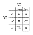
図4、図4A及び図4Bは、図2の3×3アレイでディスプレイフレームを創り出すための1つの可能性のあるアクチュエーションプロトコルを説明する。図3Bは、ピクセルが図3のヒステリシス曲線を表すために使用されることがある、列及び行電圧レベルの可能性のあるセットを説明する。図3Bの実施形態では、ピクセルをアクチュエートすることは、適切な列を−Vbiasに、そして適切な行を+ΔVに設定することを含む。これは、それぞれ−5V及び+5Vに対応することができる。ピクセルを弛緩させることは、適切な列を+Vbiasに、そして適切な行を同じ+ΔVに設定することにより達成され、ピクセル間で零ボルトの電位差を生成する。そこでは行電圧が零ボルトに保持されるこれらの行では、列が+Vbias又は−Vbiasであるかに拘らず、ピクセルが元々あった状態がどうであろうとも、ピクセルは、その状態で安定である。また、図3Bに示すように、上に記載した電圧とは異極性の電圧を使用することができる。例えば、ピクセルをアクチュエートすることは、適切な列を+Vbiasに、そして適切な行を−ΔVに設定することを含むことができる。この実施形態において、ピクセルをリリースすることは、適切な列を−Vbiasに設定し、適切な行を同じ−ΔVに設定し、ピクセルの全域でゼロボルトの電位差を生成することにより達成される。 4 , 4A and 4B illustrate one possible actuation protocol for creating a display frame with the 3 × 3 array of FIG. Figure 3B pixels may be used to represent the hysteresis curve of FIG. 3, illustrating a possible set of column and row voltage levels. In the embodiment of FIG. 3B, actuating the pixels includes setting the appropriate column to −Vbias and the appropriate row to + ΔV. This can correspond to -5V and + 5V, respectively. Relaxing the pixels is accomplished by setting the appropriate column to + Vbias and the appropriate row to the same + ΔV, producing a zero volt potential difference between the pixels. In these rows where the row voltage is held at zero volts, the pixel is stable in that state no matter what the pixel was originally in, regardless of whether the column is + Vbias or -Vbias. is there. Further, as shown in FIG. 3B, a voltage having a different polarity from the voltage described above can be used. For example, actuating a pixel can include setting the appropriate column to + Vbias and the appropriate row to -ΔV. In this embodiment, releasing the pixel is accomplished by setting the appropriate column to -Vbias, the appropriate row to the same -ΔV, and generating a zero volt potential difference across the pixel.
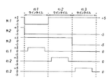
図4Bは、そこではアクチュエートされたピクセルが反射しない図4Aに説明されたディスプレイ配列に結果としてなる、図2の3×3アレイに印加される一連の行及び列信号を示すタイミング図である。図4Aに説明されたフレームを書き込むことに先立って、ピクセルは、任意の状態であることができ、そしてこの例では、全ての行が0ボルトであり、全ての列が+5ボルトである。これらの印加電圧で、全てのピクセルは、自身の現在のアクチュエートされた状態又は弛緩された状態で安定である。 FIG. 4B is a timing diagram showing a series of row and column signals applied to the 3 × 3 array of FIG. 2, resulting in the display arrangement described in FIG. 4A where the actuated pixels do not reflect. . Prior to writing the frame described in FIG. 4A, the pixels can be in any state, and in this example, all rows are 0 volts and all columns are +5 volts. With these applied voltages, all pixels are stable in their current actuated or relaxed state.
図4Aのフレームでは、ピクセル(1,1)、(1,2)、(2,2)、(3,2)及び(3,3)がアクチュエートされている。これを実現するために、行1に対する"ライン時間"の期間に、列1及び2は、−5ボルトに設定され、そして列3は、+5ボルトに設定される。全てのピクセルが3−7ボルトの安定ウィンドウの中に留まるため、これは、どのピクセルの状態も変化させない。行1は、その後、0から5ボルトまで上がり、零に戻るパルスでストローブされる。これは、(1,1)及び(1,2)ピクセルをアクチュエートし、(1,3)ピクセルを弛緩する。アレイ中のその他のピクセルは、影響されない。望まれるように行2を設定するために、列2は、−5ボルトに設定され、そして列1及び3は、+5ボルトに設定される。行2に印加された同じストローブは、その後、ピクセル(2,2)をアクチュエートし、ピクセル(2,1)及び(2,3)を弛緩する。再び、アレイのその他のピクセルは、影響されない。行3は、列2及び3を−5ボルトに、そして列1を+5ボルトに設定することより同様に設定される。行3ストローブは、図4Aに示されたように行3ピクセルを設定する。フレームを書き込んだ後、行電位は零に、そして列電位は+5又は−5ボルトのいずれかに留まることができ、ディスプレイは、その後、図4Aの配列で安定である。同じ手順が数十から数百の行及び列のアレイに対して採用されることができることが、理解されるであろう。しかも、行及び列アクチュエーションを実行するために使用された電圧のタイミング、シーケンス、及びレベルが、上記に概要を示された一般的な原理の範囲内で広範囲に変化されることができ、そして、上記の例は、具体的な例だけであり、任意のアクチュエーション電圧方法は、本発明とともに使用されることができる。
In the frame of FIG. 4A, pixels (1,1), (1,2), (2,2), (3,2) and (3,3) are actuated. To accomplish this, during the "line time" period for
図5Aおよび5Bは、ディスプレイ装置40の一実施形態を図示するシステムブロック図である。ディスプレイ装置40は、例えば、セルラー電話またはモバイル電話であり得る。しかしながら、ディスプレイ装置40の同じコンポーネントまたはその多少の変形物もまた種々のタイプのテレビおよびポータブルメディアプレイヤーを例証する。
5A and 5B are system block diagrams illustrating one embodiment of
ディスプレイ装置40は、ハウジング41、ディスプレイ30、アンテナ43、スピーカー44、入力装置48、およびマイクロフォン46を含む。ハウジング41は、一般的に、射出成形および真空成形を含む、当業者によく知られた様々な製造プロセスのいずれかから成形される。さらに、ハウジング41は、これらに限定されないが、プラスチック、金属、ガラス、ゴム、および陶器またはそれらの組み合わせから成形してもよい。一実施形態において、ハウジング41は、異なる色のまたは異なるロゴ、画像、またはシンボルを含む他の取り外し可能な部分と交換してもよい取り外し可能な部分(図示せず)を含む。
The
例示ディスプレイ装置40のディスプレイ30は、ここに記述されるように、双安定ディスプレイを含む様々なディスプレイのいずれかであってよい。他の実施形態において、ディスプレイ30は、当業者によく知られているように、上述したプラズマ、EL、OLED、STN、LCDまたはTFT LCDのようなフラットパネルディスプレイ、またはCRTまたは他の管デバイスのような非フラットパネルディスプレイを含む。しかしながら、この実施形態について記述する目的のために、ここに記述されるように、ディスプレイ30は干渉変調器ディスプレイを含む。
The
例示ディスプレイ装置40の一実施形態のコンポーネントは、概略的に図5Bに図解される。図解される例示ディスプレイ装置40は、ハウジングを含み、少なくとも一部がその中に入れられるさらなるコンポーネントを含むことができる。例えば、一実施形態において、例示ディスプレイ装置40は、トランシーバー47に接続されたアンテナ43を含むネットワークインターフェース27を含む。トランシーバー47はプロセッサー21に接続される。プロセッサー21は調整ハードウェア52に接続される。調整ハードウェア52は信号を条件付ける(例えば、信号をフィルターする)ように構成してもよい。調整ハードウェア52は、スピーカー44およびマイクロフォン46に接続される。プロセッサー21はまた、入力装置48およびドライバーコントローラー29に接続される。ドライバーコントローラー29は、フレームバッファー28およびアレイドライバー22に接続される。アレイドライバー22は、ディスプレイアレイ30に接続される。電源50は、特定の例示ディスプレイ装置40設計により必要とされるすべてのコンポーネントに電力を供給する。
The components of one embodiment of
例示ディスプレイ装置40がネットワーク上で1つ以上の装置と通信することができるように、ネットワークインターフェース27は、アンテナ43およびトランシーバー47を含む。一実施形態において、ネットワークインターフェース27は、また、プロセッサー21の必要条件を軽減するためにいくつかの処理能力を有していてもよい。アンテナ43は、信号を送信し受信する当業者に知られた任意のアンテナである。一実施形態において、アンテナは、IEEE 802.11(a)、(b)または(g)を含むIEEE802.11規格に従ってRF信号を送信し受信する。他の実施形態において、アンテナはBLUETOOTH規格に従ってRF信号を送信し受信する。携帯電話の場合には、アンテナは、CDMA,GSM、AMPSまたは無線携帯電話内で通信するために使用される他の周知の信号を受信するように設計される。トランシーバー47は、信号がプロセッサー21により受信され、さらにプロセッサー21によりさらに操作されるように、アンテナ43から受信した信号を前処理する。トランシーバー47は、また、信号がアンテナ43を介して例示ディスプレイ装置40から送信されるように、プロセッサー21から受信した信号を処理する。
The
他の実施例において、トランシーバー47は受信機と交換することができる。さらに他の実施形態において、ネットワークインターフェース27は任意の画像ソースと交換することができる。画像ソースは、プロセッサー21に送られる画像データを記憶または発生することができる。例えば、画像ソースは、デジタルビデオディスク(DVD)または画像データを含むハードディスクドライブ、または画像データを発生するソフトウェアモジュールであり得る。
In other embodiments, the
プロセッサー21は、一般に例示ディスプレイ装置40の全体動作を制御する。
The
プロセッサー21は、ネットワークインターフェース27あるいは画像ソースからの圧縮画像データのようなデータを受信し、データを生の画像データまたは生の画像データに直ちに処理できるフォーマットに処理する。次に、プロセッサー21は処理されたデータを記憶のためにドライバーコントローラー29またはフレームバッファー28に送信する。生データは、典型的には画像内の各場所における画像特性を識別する情報を指す。例えば、そのような画像特性は、色、飽和およびグレイスケールレベルを含むことができる。
The
一実施形態において、プロセッサー21はマイクロコントローラー、CPUあるいは例示ディスプレイ装置40の動作を制御するための論理装置を含む。調整ハードウェア52は、一般に信号をスピーカー44に送信するため、およびマイクロフォン46からの信号を受信するために増幅器およびフィルターを含む。調整ハードウェア52は、例示ディスプレイ装置40内のディスクリートコンポーネントであってもよいし、またはプロセッサーまたは他のコンポーネント内に組み込んでもよい。
In one embodiment, the
ドライバーコントローラー29は、プロセッサー21によって発生された生の画像データを、直接プロセッサー21からまたはフレームバッファー28から取り、アレイドライバー22への高速送信のために適切に生の画像データを再フォーマットする。具体的には、ドライバーコントローラー29は、ディスプレイアレイ30全域で走査するのに適した時間オーダーを有するように、ラスター状のフォーマットを持つデータフローへ生の画像データを再フォーマットする。次に、ドライバーコントローラー29はアレイドライバー22にフォーマットされた情報を送る。LCDコントローラーのようなドライバーコントローラー29はしばしばスタンドアロン集積回路(IC)としてシステムプロセッサー21に関連するが、そのようなコントローラーは、多くの方法で実施してもよい。それらはハードウェアとしてプロセッサー21に埋め込んでもよいし、あるいはソフトウェアとしてプロセッサー21に埋め込んでもよいし、またはハードウェアで、アレイドライバー22に完全に一体化してもよい。
The
典型的に、アレイドライバー22は、ドライバーコントローラー29からフォーマットされた情報を受信し、ディスプレイのx−yのピクセルのマトリクスから来る何百ときには何千のリード線に毎秒多くの回数印加される波形の並列セットにビデオデータを再フォーマットする。
Typically, the
一実施形態において、ドライバーコントローラー29、アレイドライバー22およびディスプレイアレイ30は、ここに記述されたディスプレイのタイプのうちのどれにも適切である。例えば、一実施形態において、ドライバーコントローラー29は、従来のディスプレイコントローラーまたは双安定ディスプレイコントローラー(例えば、干渉変調器コントローラー)である。他の実施形態において、アレイドライバー22は、従来のドライバーあるいは双安定ディスプレイドライバー(例えば干渉変調器ディスプレイ)である。一実施形態において、ドライバーコントローラー29はアレイドライバー22と一体化される。そのような実施形態は、高度に集積されたシステム、例えば携帯電話、時計、および他の小型面積のディスプレイに一般的である。さらに他の実施形態において、ディスプレイアレイ30は、典型的なディスプレイアレイまたは双安定アレイ(例えば、干渉変調器のアレイを含むディスプレイ)である。
In one embodiment,
入力装置48は、ユーザーが典型的なディスプレイ装置40の動作を制御することを可能にする。一実施形態において、入力装置48は、QWERTYキーボードあるいは電話キーパッド、ボタン、スイッチ、タッチセンシティブスクリーン、圧力または熱感知可能な薄膜のようなキーパッドを含む。一実施形態において、マイクロフォン46は例示ディスプレイ装置40のための入力装置である。データを装置に入力するためにマイクロフォン46が使用されるとき、例示ディスプレイ装置40の動作を制御するためにユーザーにより音声コマンドが供給されてもよい。
技術的によく知られているように、電源50は、様々なエネルギー記憶装置を含むことができる。例えば、一実施形態において、電源50は、ニッケルカドミウム電池またはリチウムイオン電池のような2次電池である。他の実施形態において、電源50は、再生可能エネルギーソース、コンデンサー、またはプラスチック太陽電池および太陽電池ペイントを含む太陽電池である。他の実施形態において、電源50は壁コンセントから電力を受信するように構成される。
As is well known in the art, the
いくつかの実施において、上述したように、コントロールプログラマビリティ(control programmability)は、電子ディスプレイシステム内のいくつかの場所に位置することができるドライバーコントローラー内に存在する。いくつかの場合、コントロールプログラマビリティは、アレイドライバー22に存在する。当業者は、成就した最適化は、任意の数のハードウェアおよび/またはソフトウェアコンポーネントおよび様々な構成において実施してもよいことを認識するであろう。
In some implementations, as described above, control programmability exists in a driver controller that can be located at several locations within the electronic display system. In some cases, control programmability exists in the
上で述べた原理に従って動作する干渉変調器の構造の詳細は、広範囲に変化してもよい。 The details of the structure of interferometric modulators that operate in accordance with the principles set forth above may vary widely.
例えば、図6A−図6Cは、移動鏡構造の3つの異なる実施形態を図示する。図6Aは、図1の実施形態の断面であり、そこでは金属材料14のストライプが、直角に延びている支柱18上に堆積される。図6Bでは、可動反射材料14は、連結部(tether)32上に、角だけで支柱に取り付けられる。図6Cでは、可動反射材料14は、変形可能な層34から吊り下げられる。反射材料14に使用される構造的な設計及び材料が光学的特性に関して最適化されることができるため、及び変形可能な層34に使用される構造的な設計及び材料が所望の機械的特性に関して最適化できるため、この実施形態は、利点を有する。種々のタイプの干渉装置の製造は、例えば、米国公開出願2004/0051929を含む、種々の公開された文書に記載されている。多種多様な周知の技術が、一連の材料堆積、パターニング、及びエッチング工程を含む、上記に説明された構造を製造するために使用されることができる。
For example, FIGS. 6A-6C illustrate three different embodiments of the moving mirror structure. FIG. 6A is a cross section of the embodiment of FIG. 1, where a stripe of
図1および図2に示すように、および上で議論したように、ピクセルアレイ30の各キャビティは、行ドライバー回路24によりチャージされるコンデンサーを形成する。列電極14bが行電極16bに非常接近するように移動するので、容量値は、任意の特別な作動されたピクセル12bに対して相対的に大きい。異なる数のキャビティは、所定の行パルス期間中に作動してもよいので、行ドライバー回路が見るそのインピーダンスは、高度に可変かもしれない。
As shown in FIGS. 1 and 2, and as discussed above, each cavity of the
図7は、フィルター回路325a、325b、325cが、行電極16a、16b、16cおよび行ドライバー回路24との間の基板20上に配置される一実施形態を示す。そのようなフィルター回路325a、325b、325cは、行ドライバー回路24により駆動されるインピーダンスを制御するために有用であることがわかった。例えばそのようなフィルター回路325a、325b、325cは、インピーダンスの安定性を制御するために使用してもよいし、インピーダンスが異なる行パルスに対して変更可能にするために使用してもよい。図示した実施形態において、フィルター回路325a、325b、325cの各々は、それぞれコンデンサー328a、328b、328cおよび抵抗器329a、329b、329cを含む。フィルター回路325a−c、コンデンサー328a−cおよび抵抗器329a−cは、ピクセルアレイ30に組み込んでもよい電気装置の例である。電気装置の他の例はインダクター(図7には示されない)を含む。例えば、一実施形態において、フィルターは少なくとも1つのコンデンサー、少なくとも1つの抵抗器および少なくとも1つのインダクターを含む。そのような電気装置は、ピクセルアレイ30の様々な領域に組み込んでもよいし種々の目的のために使用してもよい。例えば、フィルター回路、コンデンサー、抵抗器および/またはインダクターのような電気装置は、列ドライバー回路26と列電極14(図7に示していない)の間に配置してもよい。図7は、干渉変調器の3×3アレイ30を図示するけれども、ここに記載されるディスプレイパネルまたは装置は、数百、数千あるいは数百万の個々の干渉変調器を含むアレイを構成してもよい。
FIG. 7 shows an embodiment in which the
一実施形態において、電気装置は、基板20のエッジまたは周辺領域36においてまたはその付近でピクセルアレイ30に組み込んでもよい。しかしながら、ある場合には、基板20の周辺の領域36での、あるいはその領域の近くの電気装置の組み込みは、不便または望ましくない。例えば、比較的大きな容量値があるコンデンサーは、ある配置で利用してもよい。そのようなコンデンサーは比較的大きなコンデンサプレートエリアを持っているかもしれないし、および/または比較的多数の中で使用されるかもしれないし、従って、ピクセルアレイ30に利用可能な基板20のエリアを縮小するある場合に、基板20の周辺領域36で、あるいはその領域の近くに相応に広い面積を占有してもよい。
In one embodiment, the electrical device may be incorporated into the
ここに記述された様々な実施形態は、特に基板20とピクセルアレイ30の間で、アレイによって占有される基板の同じ領域または設置面積内の場所を含むデバイス内の、様々な場所で組込んでもよい、1つ以上の透明な電気装置を含むディスプレイ装置を提供する。したがって、例えば、干渉変調器を含むディスプレイ装置の設計は、装置のエッジで、またはエッジの近くでのみフィルター、抵抗器、コンデンサーおよびインダクターのような電気装置を置くように制約される必要はない。代わりに、種々の実施形態は、デバイスの視野領域に含まれていてもよい透明な電気装置を供給することにより設計の柔軟性を増大させることができる。
The various embodiments described herein may be incorporated at various locations within the device, particularly between the
「透明な」電気装置がすべての可視光線で入射光の100%を送信する必要がないことが理解されるだろう。ディスプレイ装置の視野領域に組み込まれるとき、視野領域内の透明電気装置を含まない別の類似する装置に比べて、一般的に類似のまたは改良された方法で装置が機能できるように十分な入射光を送信することができるならば電気装置は「透明である」と考えられる。多くの場合、透明な電気装置は、入射光照射の少なくとも約80%、より望ましくは約90%送信する。従って、上述の記載から透明な電気装置を作るために使用されるすべての材料がそれ自体透明である必要は無いということになる。例えば、(金属のような)種々の材料はそのような少量の中で使用されおよび/またはそのような薄層に堆積されるかもしれないし、および/または別の材料中で非常に微細に分散される。従って、バルク材が通常それ自体透明であると考えられない場合においても、透明性は、達成される。 It will be appreciated that a “transparent” electrical device need not transmit 100% of the incident light with all visible light. When incorporated into the viewing area of a display device, sufficient incident light is generally sufficient to allow the device to function in a similar or improved manner compared to another similar device that does not include a transparent electrical device within the viewing area. Can be considered “transparent”. In many cases, the transparent electrical device transmits at least about 80%, more desirably about 90% of the incident light radiation. Thus, from the above description, all materials used to make a transparent electrical device need not be transparent per se. For example, various materials (such as metals) may be used in such small amounts and / or deposited in such thin layers and / or very finely dispersed in another material Is done. Thus, transparency is achieved even when the bulk material is not normally considered to be transparent per se.
フィルター、抵抗器、コンデンサーおよびインダクターを含む種々の電気装置がここに記載される。特に指定の無い限り、ここに使用されるようにこれらの用語は、当業者により理解される通常の意味を持つ。例えば、コンデンサーは記憶コンデンサーであってもよい。好ましいコンデンサーの例は、約10ピコファラッド乃至約0.1マイクロファラッドのレンジのキャパシタンスを持つコンデンサーを含む。好ましい抵抗器の例は、約100オーム乃至約1ギガオームのレンジの抵抗値を持つ抵抗器を含む。好ましいインダクターの例は、約1ナノヘンリー乃至約10マイクロヘンリーのインダクタンスを持つインダクターを含む。ここに記述された電気装置の各々は、以下に記載するすべての実施形態において、単独で、グループまたは2以上の類似の装置で、または異なる2以上の装置からなるグループで使用してもよい。同様に、特定の実施形態のコンテキストで図示されるけれども、種々の特徴はまた他の実施形態において、利用してもよいことは理解されるであろう。 Various electrical devices are described herein, including filters, resistors, capacitors and inductors. Unless otherwise specified, as used herein, these terms have their ordinary meanings as understood by one of ordinary skill in the art. For example, the capacitor may be a storage capacitor. Examples of preferred capacitors include capacitors having a capacitance in the range of about 10 picofarads to about 0.1 microfarads. Examples of preferred resistors include resistors having resistance values in the range of about 100 ohms to about 1 gigaohm. Examples of preferred inductors include inductors having an inductance of about 1 nanohenry to about 10 microhenries. Each of the electrical devices described herein may be used alone, in a group or in two or more similar devices, or in a group of two or more different devices in all embodiments described below. Similarly, although illustrated in the context of particular embodiments, it will be understood that various features may also be utilized in other embodiments.
一実施形態は、透明な基板上に配置した干渉変調器のアレイ、および干渉変調器のアレイと透明基板の間に配置した透明電気装置からなるディスプレイパネルを提供する。透明電気装置は、電気的に干渉変調器のアレイに接続される。透明な電気装置は、コンデンサー、抵抗器のような受動の電気装置、インダクターおよび/またはフィルターであってよい。透明な電気装置は、個々の電装品の様々な組合せを含んでもよいことが理解されるだろう。例えば、フィルターは抵抗器および図7に示すようなコンデンサーを含んでいてもよい。 One embodiment provides a display panel comprising an array of interferometric modulators disposed on a transparent substrate and a transparent electrical device disposed between the array of interferometric modulators and the transparent substrate. The transparent electrical device is electrically connected to the array of interferometric modulators. The transparent electrical device may be a passive electrical device such as a capacitor, resistor, inductor and / or filter. It will be appreciated that a transparent electrical device may include various combinations of individual electrical components. For example, the filter may include a resistor and a capacitor as shown in FIG.
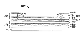
図8Aは、ディスプレイパネルまたは装置の実施形態800を図示する断面概略図である。ディスプレイパネル800は、透明基板20上に配置した干渉変調器805を含む。ディスプレイパネル800は、干渉変調器805と透明基板20の間に配置した透明コンデンサー815を含む。干渉変調器805は、上で記載した干渉変調器12bと類似しており、(作動位置に示される)可動層14b、固定層16b、および支柱18を含む。干渉変調器805はまた、固定層16b上に配置した誘電体層820を含み、短絡を防止するとともに、作動位置にある可動層14bと固定層16bとの間の分離距離を制御する。誘電体層820は、酸化シリコンのような誘電材料から形成してもよい。固定層16bは、望ましくは、クロミウムおよびインジウム錫オキサイド(ITO)の副層(図示せず)を含む。また、可動層14は望ましくはアルミニウムからなる。干渉変調器805は、透明基板20を通して見える、従って透明基板20は、ディスプレイパネル800の視界側にあると考えられる。従って、固定層16bの厚みは、固定層がディスプレイパネル800の動作中に透明であるように選択される。
FIG. 8A is a cross-sectional schematic diagram illustrating an
図8Aにおいて、透明コンデンサー815は、透明絶縁層825により干渉変調器805の固定層16bから分離されている。透明絶縁層は酸化シリコンを含んでいてもよい。透明コンデンサー815はコンデンサー誘電体層840によって互いから分離された、第1のコンデンサー層830と第2のコンデンサー層835を含む。第1と第2のコンデンサー層830および835は、望ましくは、ITOのような透明な電気コンダクターから形成される。コンデンサー誘電体層840は、望ましくはむしろ酸化シリコン(k〜4.1)のような透明な誘電材料を含む。コンタクト(contacts)(図示せず)は、透明なコンデンサー815を一般的にアレイ(例えば、重なる干渉変調器805および/またはアレイ内の干渉変調器)に電気的に接続し、およびドライバーのような他の回路網に接続する。
In FIG. 8A, the
上述するように、図示した実施形態において、透明基板20は、ディスプレイパネル800の視界側にあると考えられる。したがって、透明なコンデンサー815は、透明基板20の視界側から干渉変調器805に光を送信するように構成された透明な受動電気装置の一例である。図示した構成において、透明コンデンサー815および干渉変調器805は、それらが組み込まれるディスプレイ装置のアレイ領域内の基板20に(直接または間接的に)取り付けられる。
As described above, in the illustrated embodiment, the
図8Bは、ディスプレイパネル実施形態850を図示する横断面の概略図である。
FIG. 8B is a cross-sectional schematic diagram illustrating a
ディスプレイパネルは、それが図8Aに図示したコンデンサー815の代わりにフィルター325を含むことを除いて、ディスプレイパネル800と同様である。フィルター325はコンデンサー815aおよび抵抗器329を含む。コンデンサー815aは、両方が第1のコンデンサー層830および第2のコンデンサー層835を含むという点において図8Aに図示したコンデンサー815と類似している。しかしながら、コンデンサー815aでは、第1と第2のコンデンサー層830および835は、透明な抵抗器329を含むコンデンサー誘電体層840aによって互いに分けられる。透明な抵抗器329は電気的に第1と第2のコンデンサー層830および835を接続する。図示する実施形態において、透明な抵抗器329は、約10kΩの抵抗を有する。
The display panel is similar to the
抵抗器がコンデンサーに取り付けられていない実施形態および/またはディスプレイパネルがコンデンサーを含ない実施形態を含む、他の実施形態において、抵抗器は、上述したように、約100オーム乃至約1ギガオームのレンジの抵抗値を有する。抵抗器は、絶縁体の抵抗値とコンダクターとの間の中間である抵抗値を有した抵抗器を供給するのに効果的な(金属のような)電気的導電材料の量を用いてドーピングされた(透明ポリマーまたは酸化シリコンのような)透明絶縁体を含んでいてもよい。 In other embodiments, including embodiments in which the resistor is not attached to the capacitor and / or the display panel does not include the capacitor, the resistor may range from about 100 ohms to about 1 gigaohm, as described above. The resistance value is as follows. The resistor is doped with an amount of electrically conductive material (such as a metal) effective to provide a resistor having a resistance value that is intermediate between the resistance value of the insulator and the conductor. It may also contain a transparent insulator (such as a transparent polymer or silicon oxide).
図9はインダクター実施形態900を図示する概略斜視図である。インダクター900は、一般に、第2コンダクター920に接続されたスパイラルコンダクター910を含む。一般的にスパイラルコンダクター910は、第1の平面内に形成され、第2コンダクター920は、一般的に第1平面と平行である第2平面内に形成される。一般的にスパイラルコンダクター910は、一般的に第1平面905と第2平面915に垂直な横コンダクター912を介して第2コンダクター920に接続される。インダクター900は、当業者に知られた方法により形成してもよい。例えば、平面905は、ITOのような透明な導電性金属が堆積され、一般的にスパイラル形状にパターン化される透明基板を含んでいてもよい。第2平面915は、既知の方法を使用して、第1平面905の上に堆積される酸化シリコンのような絶縁材の層を含んでいてもよい。次に、ビアホールが第2平面915を介して第2コンダクター920に形成され、次に、ITOのような導電材が充填され横コンダクター912を形成する。次に、横コンダクター912に接触させるために、第2平面915上にITOのような透明な金属を堆積してパターニングすることにより第2コンダクター920を形成してもよい。当業者に既知の他の方法も使用されてもよい、例えば米国特許第6,531,945、第6,249,039、および第6,166,422を参照されたい。インダクター900のようなインダクターは、図8Aおよび8Bのために上に記述された方法類似の方法でディスプレイパネルに組み込んでもよい。
FIG. 9 is a schematic perspective view illustrating an
ディスプレイパネル実施形態800および850は、望ましくは、例えば図7に図示するアレイ30に送信されたさらなる干渉変調器(図8Aおよび8Bに示していない)を含むことが理解されるであろう。ディスプレイパネル内の透明電気装置(例えば、コンデンサー815およびフィルター325)は、種々の方法で干渉変調器のアレイに動作可能に接続してもよい。一実施形態において、透明コンデンサー815は、図7に示すように、第2コンデンサー層835を固定層16bに電気的に接続し、第1コンデンサー層830を行ドライバー回路24に電気的に接続することにより、干渉変調器のアレイに電気的に接続される。行ドライバー回路24は、基板20の周囲上にあるかまたは基盤20から離れてある。そのような電気接続は様々な方法で遂行してもよい。例えば、図8Aおよび図8Bに関して、第2のコンデンサー層835は、ビアホールに充填される電気的導電材は、第2コンデンサー層835と固定層16bとの間の電気的接続を形成するように、例えば、透明絶縁層825内にビアホールを形成し、ビアホールを金属のような電気的導電材で充填し、次に、透明絶縁層825の上にITOの薄層を堆積し、そしてビアホールに充填されて固定層16bを形成することにより、固定層16に電気的に接続してもよい。
It will be appreciated that
透明コンデンサー815から配列への電気接続は、様々な方法で行ってもよいし、透明コンデンサー815は、複数の干渉変調器に接続してもよいことは理解されるであろう。例えば、固定層16bは、図7に示すアレイ内の複数の干渉変調器のために行ラインを形成してもよい。固定層16bへの第2のコンデンサー層835の電気接続は、固定層16bの長さに沿った様々な場所に作っても良い。透明なフィルター325は、同様のやり方で干渉変調器のアレイに電気的に接続してもよい。
It will be appreciated that the electrical connection from the
干渉変調器のアレイ内の特定の透明電気装置は、そうである必要はないが、特定の透明電気装置に最も近い個々の干渉変調器に電気的に接続してもよいことは、上記記載から理解されるであろう。同様に、干渉変調器に特定の透明電気装置が電気的に接続される必要がないことも理解されるであろう。例えば、特定の透明電気装置は、干渉変調器に関連する(例えば、パッケージ化されるまたは機械的に接続される)他の装置に電気的に接続してもよい。一実施形態は、アレイ領域を含む基板;アレイ領域内の基板に取り付けられた干渉変調器;およびアレイ領域内の基板に取り付けられた透明受動電気装置を含むディスプレイ装置を提供する。適切な透明受動電気装置の例はフィルター、抵抗器、コンデンサーおよび上に記述されるようなインダクターを含む。透明受動電気装置(複数の場合もある)は、干渉変調器と基板との間のようにアレイ領域の種々の部分に位置していてもよいし、または周辺に形成してもよい。一実施形態において、1つ以上の透明な受動電気装置は、光をアレイ領域内の基板の視野側から1つ以上の干渉変調器に送信するように構成される。そのような構成の例は上に記載され、図8Aおよび8Bに図示される。 It will be appreciated from the above description that certain transparent electrical devices in an array of interferometric modulators need not be, but may be electrically connected to individual interferometric modulators that are closest to the particular transparent electrical device. Will be understood. Similarly, it will be understood that a specific transparent electrical device need not be electrically connected to the interferometric modulator. For example, certain transparent electrical devices may be electrically connected to other devices associated with the interferometric modulator (eg, packaged or mechanically connected). One embodiment provides a display device that includes a substrate including an array region; an interferometric modulator attached to a substrate in the array region; and a transparent passive electrical device attached to the substrate in the array region. Examples of suitable transparent passive electrical devices include filters, resistors, capacitors and inductors as described above. The transparent passive electrical device (s) may be located in various parts of the array region, such as between the interferometric modulator and the substrate, or may be formed in the periphery. In one embodiment, the one or more transparent passive electrical devices are configured to transmit light from the viewing side of the substrate in the array region to the one or more interferometric modulators. Examples of such configurations are described above and illustrated in FIGS. 8A and 8B.
他の実施形態は、基板上に透明電気装置を形成し、透明電気装置の上に絶縁層を堆積し、絶縁層の上に干渉変調器を形成し、および透明電気装置と干渉変調器との間に電気接続を形成することを含む、ディスプレイ装置を作る方法を提供する。図10は、そのような方法において、あるステップを図示するプロセスフロー図である。図10に示されたステップの各々は、MEMS製作の当業者に周知の種々の方法で行ってもよい。例えば、種々様々の技術は、化学蒸着法(プラズマ化学蒸着法および熱の化学蒸着法を含む)、スピンオン(spin-on)堆積、リソグラフィー、エッチング、パターニング、クリーニング、はんだ付けおよびパッケージング技術を含む当業者に知られている。 Other embodiments form a transparent electrical device on a substrate, deposit an insulating layer on the transparent electrical device, form an interferometric modulator on the insulating layer, and the transparent electrical device and the interferometric modulator. A method of making a display device is provided that includes forming an electrical connection therebetween. FIG. 10 is a process flow diagram illustrating certain steps in such a method. Each of the steps shown in FIG. 10 may be performed in various ways well known to those skilled in the art of MEMS fabrication. For example, a wide variety of techniques include chemical vapor deposition (including plasma chemical vapor deposition and thermal chemical vapor deposition), spin-on deposition, lithography, etching, patterning, cleaning, soldering and packaging techniques. Known to those skilled in the art.
一実施形態において、透明電気装置は、化学蒸着法、パターニングおよび除去ステップの組合せによって形成される。透明電気装置の形成は望ましくは導電層および誘電体層を堆積する、例えば、上述したように第1のコンデンサー層830とコンデンサー誘電体層840を堆積することを含む。透明電気装置の形成は、図8Bに図示するように、さらに、パターニング、例えば、堆積されたコンデンサー誘電体層840をパターニングして、除去される領域を定義し、透明抵抗器329で充填してコンデンサー誘電体層840を形成することをさらに含む。
In one embodiment, the transparent electrical device is formed by a combination of chemical vapor deposition, patterning and removal steps. Formation of the transparent electrical device desirably includes depositing a conductive layer and a dielectric layer, eg, depositing a
透明電気装置の上に絶縁層を堆積することは、例えば、酸化シリコンの化学蒸着法、シリコンの化学蒸着堆積の後に酸化により酸化シリコンを形成することにより、またはスピンオングラス(spin-on glass)プロセスにより実行してもよい。そのような方法の詳細は当業者に知られている。絶縁層の上に干渉変調器を形成することは、干渉変調器の構成に応じて種々の方法で行ってもよい。例えば、図6を参照されたい。干渉変調器を作る多くの既知のプロセスがガラス基板上に堆積ステップを含んでいるので、以前に堆積された絶縁層は干渉変調器を形成する適切な基板である。 Depositing an insulating layer on a transparent electrical device can be performed, for example, by chemical vapor deposition of silicon oxide, by forming silicon oxide by oxidation after chemical vapor deposition of silicon, or by a spin-on glass process. May be executed. Details of such methods are known to those skilled in the art. The formation of the interferometric modulator on the insulating layer may be performed by various methods depending on the configuration of the interferometric modulator. For example, see FIG. Since many known processes for making interferometric modulators include a deposition step on a glass substrate, the previously deposited insulating layer is a suitable substrate for forming the interferometric modulator.
透明な電気装置と干渉変調器の間の電気接続を形成する多数の方法がある。例えば、上に記述されるように、第2のコンデンサー層835は、充填されたビアホール内の電気導電材が第2のコンデンサー層835と固定層16bとの間の電気接続を形成するように、干渉変調器を形成する前に透明絶縁層825内にビアホールを形成し、ビアホールを金属のような電気導電材で充填し、次に、透明絶縁層825および充填されたビアホールの上にITOの薄層を堆積し、固定層16bを形成することにより固定層16bに電気的に接続してもよい。側面の電気接続は、導電性金属を使用する堆積とパターニングによって形成してもよい。
There are a number of ways to form an electrical connection between a transparent electrical device and an interferometric modulator. For example, as described above, the
本発明の精神から逸脱することなく、種々さまざまな変更を行うことができることは、当業者により理解されるであろう。したがって、本発明の方法が例示に過ぎず、本発明の範囲を限定することを意図したものでなないことが明瞭に理解されなければならない。 It will be appreciated by those skilled in the art that various modifications can be made without departing from the spirit of the invention. Therefore, it should be clearly understood that the method of the present invention is illustrative only and is not intended to limit the scope of the present invention.
Claims (30)
透明基板上に配列された干渉変調器のアレイと;および
前記干渉変調器のアレイと前記透明基板との間に配置された実質的に透明な電気装置、前記透明な電気装置は、コンデンサー、抵抗器、および誘導子の少なくとも1つを含む、前記透明な電気装置は前記干渉変調器のアレイに電気的に接続されている。 A display device comprising:
An array of interferometric modulators arranged on a transparent substrate; and a substantially transparent electrical device disposed between the array of interferometric modulators and the transparent substrate, the transparent electrical device comprising a capacitor, a resistor And the transparent electrical device including at least one of a transducer and an inductor is electrically connected to the array of interferometric modulators.
アレイ領域を具備する基板;
前記アレイ領域内の基板に取り付けられた第1の干渉変調器;および
前記アレイ領域内の前記基板に取り付けられた透明受動電気装置、前記透明受動電気装置は、コンデンサー、抵抗器および誘導子の少なくとも1つを含む。 A display device comprising:
A substrate having an array region;
A first interferometric modulator attached to a substrate in the array region; and a transparent passive electrical device attached to the substrate in the array region, the transparent passive electrical device comprising at least a capacitor, a resistor and an inductor Contains one.
基板上に透明受動電気装置を形成する;
透明受動電気装置上に絶縁層を堆積する;
絶縁層の上に干渉変調器を形成する;および
前記透明受動電気装置と前記干渉変調器との間に電気接続を形成する、前記透明受動電気装置は、コンデンサー、抵抗器、および誘導子の少なくとも1つを含む。 A method of making a display device comprising:
Forming a transparent passive electrical device on the substrate;
Depositing an insulating layer on the transparent passive electrical device;
Forming an interferometric modulator on an insulating layer; and forming an electrical connection between the transparent passive electrical device and the interferometric modulator, the transparent passive electrical device comprising at least a capacitor, a resistor, and an inductor Contains one.
請求項1のディスプレイ装置;
前記ディスプレイ装置と電気通信するプロセッサー、前記プロセッサーは、画像データを処理するように構成される;および
前記プロセッサーと電気通信するメモリ装置。 A display device comprising:
The display device of claim 1;
A processor in electrical communication with the display device, the processor configured to process image data; and a memory device in electrical communication with the processor.
前記第1のコントローラーに前記画像データの少なくとも一部を送信するように構成された第2のコントローラーをさらに具備する、請求項24のディスプレイ装置。 A first controller configured to transmit at least one signal to the display device; and a second controller configured to transmit at least a portion of the image data to the first controller. 25. The display device of claim 24.
実質的に透明な基板上に配置された干渉変調器と電気通信する実質的に透明な電気装置に電圧を印加する、前記実質的に透明な電気装置は、コンデンサー、抵抗器、および誘導子の少なくとも1つを具備し、前記干渉変調器と前記実質的に透明な基板との間に堆積される;および
前記電圧が所定の閾値を越えると前記干渉変調器の固定層に対して前記干渉変調器の可動層を移動する。 A method of operating an interferometric modulator comprising:
Applying a voltage to a substantially transparent electrical device in electrical communication with an interferometric modulator disposed on a substantially transparent substrate, the substantially transparent electrical device includes capacitors, resistors, and inductors. At least one deposited between said interferometric modulator and said substantially transparent substrate; and said interferometric modulation with respect to a fixed layer of said interferometric modulator when said voltage exceeds a predetermined threshold Move the movable layer of the vessel.
Applications Claiming Priority (2)
| Application Number | Priority Date | Filing Date | Title |
|---|---|---|---|
| US61329004P | 2004-09-27 | 2004-09-27 | |
| US11/139,108 US7349136B2 (en) | 2004-09-27 | 2005-05-27 | Method and device for a display having transparent components integrated therein |
Publications (3)
| Publication Number | Publication Date |
|---|---|
| JP2006099078A JP2006099078A (en) | 2006-04-13 |
| JP2006099078A5 JP2006099078A5 (en) | 2006-06-01 |
| JP4399404B2 true JP4399404B2 (en) | 2010-01-13 |
Family
ID=35462198
Family Applications (1)
| Application Number | Title | Priority Date | Filing Date |
|---|---|---|---|
| JP2005243761A Expired - Fee Related JP4399404B2 (en) | 2004-09-27 | 2005-08-25 | Method and apparatus for a display with integrated transparent components |
Country Status (13)
| Country | Link |
|---|---|
| US (1) | US7349136B2 (en) |
| EP (1) | EP1640336B1 (en) |
| JP (1) | JP4399404B2 (en) |
| KR (1) | KR101195100B1 (en) |
| AT (1) | ATE510794T1 (en) |
| AU (1) | AU2005203530A1 (en) |
| BR (1) | BRPI0503867A (en) |
| CA (1) | CA2517328A1 (en) |
| MX (1) | MXPA05009861A (en) |
| MY (1) | MY139407A (en) |
| RU (1) | RU2005129903A (en) |
| SG (1) | SG121077A1 (en) |
| TW (1) | TW200627346A (en) |
Families Citing this family (19)
| Publication number | Priority date | Publication date | Assignee | Title |
|---|---|---|---|---|
| US7652814B2 (en) | 2006-01-27 | 2010-01-26 | Qualcomm Mems Technologies, Inc. | MEMS device with integrated optical element |
| US7450295B2 (en) * | 2006-03-02 | 2008-11-11 | Qualcomm Mems Technologies, Inc. | Methods for producing MEMS with protective coatings using multi-component sacrificial layers |
| CA2544457C (en) | 2006-04-21 | 2009-07-07 | Mostar Directional Technologies Inc. | System and method for downhole telemetry |
| US7706042B2 (en) | 2006-12-20 | 2010-04-27 | Qualcomm Mems Technologies, Inc. | MEMS device and interconnects for same |
| US7719752B2 (en) | 2007-05-11 | 2010-05-18 | Qualcomm Mems Technologies, Inc. | MEMS structures, methods of fabricating MEMS components on separate substrates and assembly of same |
| US8400408B2 (en) * | 2007-06-13 | 2013-03-19 | Apple Inc. | Touch screens with transparent conductive material resistors |
| US7570415B2 (en) * | 2007-08-07 | 2009-08-04 | Qualcomm Mems Technologies, Inc. | MEMS device and interconnects for same |
| US20090078316A1 (en) * | 2007-09-24 | 2009-03-26 | Qualcomm Incorporated | Interferometric photovoltaic cell |
| US7864403B2 (en) * | 2009-03-27 | 2011-01-04 | Qualcomm Mems Technologies, Inc. | Post-release adjustment of interferometric modulator reflectivity |
| WO2011130715A2 (en) | 2010-04-16 | 2011-10-20 | Flex Lighting Ii, Llc | Illumination device comprising a film-based lightguide |
| WO2011130718A2 (en) | 2010-04-16 | 2011-10-20 | Flex Lighting Ii, Llc | Front illumination device comprising a film-based lightguide |
| JP2013544370A (en) * | 2010-08-17 | 2013-12-12 | クォルコム・メムズ・テクノロジーズ・インコーポレーテッド | Operation and calibration of charge neutral electrodes in interference display devices |
| JP5779852B2 (en) | 2010-08-25 | 2015-09-16 | セイコーエプソン株式会社 | Tunable interference filter, optical module, and optical analyzer |
| JP5707780B2 (en) | 2010-08-25 | 2015-04-30 | セイコーエプソン株式会社 | Wavelength variable interference filter, optical module, and optical analyzer |
| US8786592B2 (en) * | 2011-10-13 | 2014-07-22 | Qualcomm Mems Technologies, Inc. | Methods and systems for energy recovery in a display |
| US20130120327A1 (en) * | 2011-11-11 | 2013-05-16 | Qualcomm Mems Technologies, Inc. | Storage capacitor for electromechanical systems and methods of forming the same |
| US20140268273A1 (en) * | 2013-03-15 | 2014-09-18 | Pixtronix, Inc. | Integrated elevated aperture layer and display apparatus |
| US10029908B1 (en) * | 2016-12-30 | 2018-07-24 | Texas Instruments Incorporated | Dielectric cladding of microelectromechanical systems (MEMS) elements for improved reliability |
| DE102020207184B3 (en) | 2020-06-09 | 2021-07-29 | TechnoTeam Holding GmbH | Method for determining the start of relaxation after an image burn-in process on optical display devices that can be controlled pixel by pixel |
Family Cites Families (175)
| Publication number | Priority date | Publication date | Assignee | Title |
|---|---|---|---|---|
| US2534846A (en) | 1946-06-20 | 1950-12-19 | Emi Ltd | Color filter |
| DE1288651B (en) | 1963-06-28 | 1969-02-06 | Siemens Ag | Arrangement of electrical dipoles for wavelengths below 1 mm and method for producing such an arrangement |
| US3616312A (en) | 1966-04-15 | 1971-10-26 | Ionics | Hydrazine manufacture |
| FR1603131A (en) | 1968-07-05 | 1971-03-22 | ||
| US3567847A (en) * | 1969-01-06 | 1971-03-02 | Edgar E Price | Electro-optical display system |
| US3813265A (en) | 1970-02-16 | 1974-05-28 | A Marks | Electro-optical dipolar material |
| US3653741A (en) | 1970-02-16 | 1972-04-04 | Alvin M Marks | Electro-optical dipolar material |
| US3725868A (en) | 1970-10-19 | 1973-04-03 | Burroughs Corp | Small reconfigurable processor for a variety of data processing applications |
| US3699242A (en) * | 1971-02-24 | 1972-10-17 | Edgar E Price | Electro-optical display system |
| DE2336930A1 (en) | 1973-07-20 | 1975-02-06 | Battelle Institut E V | INFRARED MODULATOR (II.) |
| US4099854A (en) | 1976-10-12 | 1978-07-11 | The Unites States Of America As Represented By The Secretary Of The Navy | Optical notch filter utilizing electric dipole resonance absorption |
| US4196396A (en) | 1976-10-15 | 1980-04-01 | Bell Telephone Laboratories, Incorporated | Interferometer apparatus using electro-optic material with feedback |
| US4389096A (en) | 1977-12-27 | 1983-06-21 | Matsushita Electric Industrial Co., Ltd. | Image display apparatus of liquid crystal valve projection type |
| US4663083A (en) | 1978-05-26 | 1987-05-05 | Marks Alvin M | Electro-optical dipole suspension with reflective-absorptive-transmissive characteristics |
| US4445050A (en) | 1981-12-15 | 1984-04-24 | Marks Alvin M | Device for conversion of light power to electric power |
| US4228437A (en) | 1979-06-26 | 1980-10-14 | The United States Of America As Represented By The Secretary Of The Navy | Wideband polarization-transforming electromagnetic mirror |
| NL8001281A (en) | 1980-03-04 | 1981-10-01 | Philips Nv | DISPLAY DEVICE. |
| DE3012253A1 (en) | 1980-03-28 | 1981-10-15 | Hoechst Ag, 6000 Frankfurt | METHOD FOR VISIBLE MASKING OF CARGO IMAGES AND A DEVICE SUITABLE FOR THIS |
| US4377324A (en) * | 1980-08-04 | 1983-03-22 | Honeywell Inc. | Graded index Fabry-Perot optical filter device |
| US4441791A (en) | 1980-09-02 | 1984-04-10 | Texas Instruments Incorporated | Deformable mirror light modulator |
| FR2506026A1 (en) | 1981-05-18 | 1982-11-19 | Radant Etudes | METHOD AND DEVICE FOR ANALYZING A HYPERFREQUENCY ELECTROMAGNETIC WAVE RADIATION BEAM |
| NL8103377A (en) | 1981-07-16 | 1983-02-16 | Philips Nv | DISPLAY DEVICE. |
| US4571603A (en) * | 1981-11-03 | 1986-02-18 | Texas Instruments Incorporated | Deformable mirror electrostatic printer |
| NL8200354A (en) | 1982-02-01 | 1983-09-01 | Philips Nv | PASSIVE DISPLAY. |
| US4500171A (en) * | 1982-06-02 | 1985-02-19 | Texas Instruments Incorporated | Process for plastic LCD fill hole sealing |
| US4482213A (en) | 1982-11-23 | 1984-11-13 | Texas Instruments Incorporated | Perimeter seal reinforcement holes for plastic LCDs |
| US4566935A (en) * | 1984-07-31 | 1986-01-28 | Texas Instruments Incorporated | Spatial light modulator and method |
| US4710732A (en) | 1984-07-31 | 1987-12-01 | Texas Instruments Incorporated | Spatial light modulator and method |
| US4596992A (en) | 1984-08-31 | 1986-06-24 | Texas Instruments Incorporated | Linear spatial light modulator and printer |
| US4662746A (en) | 1985-10-30 | 1987-05-05 | Texas Instruments Incorporated | Spatial light modulator and method |
| US5096279A (en) * | 1984-08-31 | 1992-03-17 | Texas Instruments Incorporated | Spatial light modulator and method |
| US5061049A (en) | 1984-08-31 | 1991-10-29 | Texas Instruments Incorporated | Spatial light modulator and method |
| US4615595A (en) | 1984-10-10 | 1986-10-07 | Texas Instruments Incorporated | Frame addressed spatial light modulator |
| US4617608A (en) | 1984-12-28 | 1986-10-14 | At&T Bell Laboratories | Variable gap device and method of manufacture |
| US4660938A (en) * | 1985-03-11 | 1987-04-28 | Xerox Corporation | Optical display device |
| US5172262A (en) | 1985-10-30 | 1992-12-15 | Texas Instruments Incorporated | Spatial light modulator and method |
| GB2186708B (en) | 1985-11-26 | 1990-07-11 | Sharp Kk | A variable interferometric device and a process for the production of the same |
| GB8610129D0 (en) | 1986-04-25 | 1986-05-29 | Secr Defence | Electro-optical device |
| US4748366A (en) | 1986-09-02 | 1988-05-31 | Taylor George W | Novel uses of piezoelectric materials for creating optical effects |
| US4786128A (en) | 1986-12-02 | 1988-11-22 | Quantum Diagnostics, Ltd. | Device for modulating and reflecting electromagnetic radiation employing electro-optic layer having a variable index of refraction |
| NL8701138A (en) | 1987-05-13 | 1988-12-01 | Philips Nv | ELECTROSCOPIC IMAGE DISPLAY. |
| DE3716485C1 (en) | 1987-05-16 | 1988-11-24 | Heraeus Gmbh W C | Xenon short-arc discharge lamp |
| US4900136A (en) * | 1987-08-11 | 1990-02-13 | North American Philips Corporation | Method of metallizing silica-containing gel and solid state light modulator incorporating the metallized gel |
| US4857978A (en) | 1987-08-11 | 1989-08-15 | North American Philips Corporation | Solid state light modulator incorporating metallized gel and method of metallization |
| US4956619A (en) | 1988-02-19 | 1990-09-11 | Texas Instruments Incorporated | Spatial light modulator |
| US4856863A (en) | 1988-06-22 | 1989-08-15 | Texas Instruments Incorporated | Optical fiber interconnection network including spatial light modulator |
| US5028939A (en) | 1988-08-23 | 1991-07-02 | Texas Instruments Incorporated | Spatial light modulator system |
| JP2700903B2 (en) * | 1988-09-30 | 1998-01-21 | シャープ株式会社 | Liquid crystal display |
| US4982184A (en) * | 1989-01-03 | 1991-01-01 | General Electric Company | Electrocrystallochromic display and element |
| US5192946A (en) * | 1989-02-27 | 1993-03-09 | Texas Instruments Incorporated | Digitized color video display system |
| US5272473A (en) | 1989-02-27 | 1993-12-21 | Texas Instruments Incorporated | Reduced-speckle display system |
| US5170156A (en) | 1989-02-27 | 1992-12-08 | Texas Instruments Incorporated | Multi-frequency two dimensional display system |
| US5214420A (en) | 1989-02-27 | 1993-05-25 | Texas Instruments Incorporated | Spatial light modulator projection system with random polarity light |
| US5206629A (en) | 1989-02-27 | 1993-04-27 | Texas Instruments Incorporated | Spatial light modulator and memory for digitized video display |
| US5079544A (en) * | 1989-02-27 | 1992-01-07 | Texas Instruments Incorporated | Standard independent digitized video system |
| US5287096A (en) * | 1989-02-27 | 1994-02-15 | Texas Instruments Incorporated | Variable luminosity display system |
| US5214419A (en) | 1989-02-27 | 1993-05-25 | Texas Instruments Incorporated | Planarized true three dimensional display |
| US5162787A (en) | 1989-02-27 | 1992-11-10 | Texas Instruments Incorporated | Apparatus and method for digitized video system utilizing a moving display surface |
| US4900395A (en) * | 1989-04-07 | 1990-02-13 | Fsi International, Inc. | HF gas etching of wafers in an acid processor |
| US5022745A (en) | 1989-09-07 | 1991-06-11 | Massachusetts Institute Of Technology | Electrostatically deformable single crystal dielectrically coated mirror |
| US4954789A (en) | 1989-09-28 | 1990-09-04 | Texas Instruments Incorporated | Spatial light modulator |
| US5381253A (en) * | 1991-11-14 | 1995-01-10 | Board Of Regents Of University Of Colorado | Chiral smectic liquid crystal optical modulators having variable retardation |
| US5124834A (en) | 1989-11-16 | 1992-06-23 | General Electric Company | Transferrable, self-supporting pellicle for elastomer light valve displays and method for making the same |
| US5037173A (en) | 1989-11-22 | 1991-08-06 | Texas Instruments Incorporated | Optical interconnection network |
| US5500635A (en) * | 1990-02-20 | 1996-03-19 | Mott; Jonathan C. | Products incorporating piezoelectric material |
| CH682523A5 (en) * | 1990-04-20 | 1993-09-30 | Suisse Electronique Microtech | A modulation matrix addressed light. |
| GB9012099D0 (en) | 1990-05-31 | 1990-07-18 | Kodak Ltd | Optical article for multicolour imaging |
| US5099353A (en) * | 1990-06-29 | 1992-03-24 | Texas Instruments Incorporated | Architecture and process for integrating DMD with control circuit substrates |
| DE69113150T2 (en) * | 1990-06-29 | 1996-04-04 | Texas Instruments Inc | Deformable mirror device with updated grid. |
| US5018256A (en) | 1990-06-29 | 1991-05-28 | Texas Instruments Incorporated | Architecture and process for integrating DMD with control circuit substrates |
| US5216537A (en) | 1990-06-29 | 1993-06-01 | Texas Instruments Incorporated | Architecture and process for integrating DMD with control circuit substrates |
| US5142405A (en) | 1990-06-29 | 1992-08-25 | Texas Instruments Incorporated | Bistable dmd addressing circuit and method |
| US5083857A (en) * | 1990-06-29 | 1992-01-28 | Texas Instruments Incorporated | Multi-level deformable mirror device |
| US5153771A (en) * | 1990-07-18 | 1992-10-06 | Northrop Corporation | Coherent light modulation and detector |
| US5192395A (en) * | 1990-10-12 | 1993-03-09 | Texas Instruments Incorporated | Method of making a digital flexure beam accelerometer |
| US5044736A (en) | 1990-11-06 | 1991-09-03 | Motorola, Inc. | Configurable optical filter or display |
| US5602671A (en) * | 1990-11-13 | 1997-02-11 | Texas Instruments Incorporated | Low surface energy passivation layer for micromechanical devices |
| US5331454A (en) | 1990-11-13 | 1994-07-19 | Texas Instruments Incorporated | Low reset voltage process for DMD |
| FR2669466B1 (en) | 1990-11-16 | 1997-11-07 | Michel Haond | METHOD FOR ENGRAVING INTEGRATED CIRCUIT LAYERS WITH FIXED DEPTH AND CORRESPONDING INTEGRATED CIRCUIT. |
| US5233459A (en) | 1991-03-06 | 1993-08-03 | Massachusetts Institute Of Technology | Electric display device |
| US5136669A (en) | 1991-03-15 | 1992-08-04 | Sperry Marine Inc. | Variable ratio fiber optic coupler optical signal processing element |
| CA2063744C (en) * | 1991-04-01 | 2002-10-08 | Paul M. Urbanus | Digital micromirror device architecture and timing for use in a pulse-width modulated display system |
| US5142414A (en) | 1991-04-22 | 1992-08-25 | Koehler Dale R | Electrically actuatable temporal tristimulus-color device |
| US5226099A (en) | 1991-04-26 | 1993-07-06 | Texas Instruments Incorporated | Digital micromirror shutter device |
| FR2679057B1 (en) * | 1991-07-11 | 1995-10-20 | Morin Francois | LIQUID CRYSTAL, ACTIVE MATRIX AND HIGH DEFINITION SCREEN STRUCTURE. |
| US5179274A (en) * | 1991-07-12 | 1993-01-12 | Texas Instruments Incorporated | Method for controlling operation of optical systems and devices |
| US5168406A (en) | 1991-07-31 | 1992-12-01 | Texas Instruments Incorporated | Color deformable mirror device and method for manufacture |
| US5254980A (en) | 1991-09-06 | 1993-10-19 | Texas Instruments Incorporated | DMD display system controller |
| US5233385A (en) | 1991-12-18 | 1993-08-03 | Texas Instruments Incorporated | White light enhanced color field sequential projection |
| US5233456A (en) | 1991-12-20 | 1993-08-03 | Texas Instruments Incorporated | Resonant mirror and method of manufacture |
| US5228013A (en) | 1992-01-10 | 1993-07-13 | Bik Russell J | Clock-painting device and method for indicating the time-of-day with a non-traditional, now analog artistic panel of digital electronic visual displays |
| US5296950A (en) * | 1992-01-31 | 1994-03-22 | Texas Instruments Incorporated | Optical signal free-space conversion board |
| US5231532A (en) | 1992-02-05 | 1993-07-27 | Texas Instruments Incorporated | Switchable resonant filter for optical radiation |
| US5212582A (en) | 1992-03-04 | 1993-05-18 | Texas Instruments Incorporated | Electrostatically controlled beam steering device and method |
| DE69310974T2 (en) | 1992-03-25 | 1997-11-06 | Texas Instruments Inc | Built-in optical calibration system |
| US5312513A (en) | 1992-04-03 | 1994-05-17 | Texas Instruments Incorporated | Methods of forming multiple phase light modulators |
| WO1993021663A1 (en) * | 1992-04-08 | 1993-10-28 | Georgia Tech Research Corporation | Process for lift-off of thin film materials from a growth substrate |
| US5311360A (en) | 1992-04-28 | 1994-05-10 | The Board Of Trustees Of The Leland Stanford, Junior University | Method and apparatus for modulating a light beam |
| TW245772B (en) * | 1992-05-19 | 1995-04-21 | Akzo Nv | |
| JPH0651250A (en) * | 1992-05-20 | 1994-02-25 | Texas Instr Inc <Ti> | Monolithic space optical modulator and memory package |
| US5818095A (en) * | 1992-08-11 | 1998-10-06 | Texas Instruments Incorporated | High-yield spatial light modulator with light blocking layer |
| US5345328A (en) | 1992-08-12 | 1994-09-06 | Sandia Corporation | Tandem resonator reflectance modulator |
| US5293272A (en) * | 1992-08-24 | 1994-03-08 | Physical Optics Corporation | High finesse holographic fabry-perot etalon and method of fabricating |
| US5737050A (en) * | 1992-08-25 | 1998-04-07 | Matsushita Electric Industrial Co., Ltd. | Light valve having reduced reflected light, high brightness and high contrast |
| US5327286A (en) | 1992-08-31 | 1994-07-05 | Texas Instruments Incorporated | Real time optical correlation system |
| US5325116A (en) | 1992-09-18 | 1994-06-28 | Texas Instruments Incorporated | Device for writing to and reading from optical storage media |
| US5296775A (en) | 1992-09-24 | 1994-03-22 | International Business Machines Corporation | Cooling microfan arrangements and process |
| US6674562B1 (en) * | 1994-05-05 | 2004-01-06 | Iridigm Display Corporation | Interferometric modulation of radiation |
| US5324683A (en) | 1993-06-02 | 1994-06-28 | Motorola, Inc. | Method of forming a semiconductor structure having an air region |
| US5489952A (en) * | 1993-07-14 | 1996-02-06 | Texas Instruments Incorporated | Method and device for multi-format television |
| US5497197A (en) * | 1993-11-04 | 1996-03-05 | Texas Instruments Incorporated | System and method for packaging data into video processor |
| US5500761A (en) * | 1994-01-27 | 1996-03-19 | At&T Corp. | Micromechanical modulator |
| JPH07253594A (en) * | 1994-03-15 | 1995-10-03 | Fujitsu Ltd | Display device |
| US6680792B2 (en) * | 1994-05-05 | 2004-01-20 | Iridigm Display Corporation | Interferometric modulation of radiation |
| US6710908B2 (en) * | 1994-05-05 | 2004-03-23 | Iridigm Display Corporation | Controlling micro-electro-mechanical cavities |
| US6040937A (en) * | 1994-05-05 | 2000-03-21 | Etalon, Inc. | Interferometric modulation |
| US7550794B2 (en) * | 2002-09-20 | 2009-06-23 | Idc, Llc | Micromechanical systems device comprising a displaceable electrode and a charge-trapping layer |
| US5497172A (en) * | 1994-06-13 | 1996-03-05 | Texas Instruments Incorporated | Pulse width modulation for spatial light modulator with split reset addressing |
| US5499062A (en) * | 1994-06-23 | 1996-03-12 | Texas Instruments Incorporated | Multiplexed memory timing with block reset and secondary memory |
| US5610624A (en) * | 1994-11-30 | 1997-03-11 | Texas Instruments Incorporated | Spatial light modulator with reduced possibility of an on state defect |
| US5726480A (en) * | 1995-01-27 | 1998-03-10 | The Regents Of The University Of California | Etchants for use in micromachining of CMOS Microaccelerometers and microelectromechanical devices and method of making the same |
| US5610438A (en) * | 1995-03-08 | 1997-03-11 | Texas Instruments Incorporated | Micro-mechanical device with non-evaporable getter |
| US6969635B2 (en) * | 2000-12-07 | 2005-11-29 | Reflectivity, Inc. | Methods for depositing, releasing and packaging micro-electromechanical devices on wafer substrates |
| US5710656A (en) * | 1996-07-30 | 1998-01-20 | Lucent Technologies Inc. | Micromechanical optical modulator having a reduced-mass composite membrane |
| US5884083A (en) * | 1996-09-20 | 1999-03-16 | Royce; Robert | Computer system to compile non-incremental computer source code to execute within an incremental type computer system |
| EP0877272B1 (en) * | 1997-05-08 | 2002-07-31 | Texas Instruments Incorporated | Improvements in or relating to spatial light modulators |
| US5867302A (en) * | 1997-08-07 | 1999-02-02 | Sandia Corporation | Bistable microelectromechanical actuator |
| EP1025711A1 (en) * | 1997-10-31 | 2000-08-09 | Daewoo Electronics Co., Ltd | Method for manufacturing thin film actuated mirror array in an optical projection system |
| US6028690A (en) * | 1997-11-26 | 2000-02-22 | Texas Instruments Incorporated | Reduced micromirror mirror gaps for improved contrast ratio |
| US6180428B1 (en) * | 1997-12-12 | 2001-01-30 | Xerox Corporation | Monolithic scanning light emitting devices using micromachining |
| US6016693A (en) * | 1998-02-09 | 2000-01-25 | The Regents Of The University Of California | Microfabrication of cantilevers using sacrificial templates |
| US6195196B1 (en) * | 1998-03-13 | 2001-02-27 | Fuji Photo Film Co., Ltd. | Array-type exposing device and flat type display incorporating light modulator and driving method thereof |
| JP4074714B2 (en) * | 1998-09-25 | 2008-04-09 | 富士フイルム株式会社 | Array type light modulation element and flat display driving method |
| US6323834B1 (en) * | 1998-10-08 | 2001-11-27 | International Business Machines Corporation | Micromechanical displays and fabrication method |
| US6194323B1 (en) * | 1998-12-16 | 2001-02-27 | Lucent Technologies Inc. | Deep sub-micron metal etch with in-situ hard mask etch |
| US6335831B2 (en) * | 1998-12-18 | 2002-01-01 | Eastman Kodak Company | Multilevel mechanical grating device |
| US6537427B1 (en) * | 1999-02-04 | 2003-03-25 | Micron Technology, Inc. | Deposition of smooth aluminum films |
| JP3592136B2 (en) * | 1999-06-04 | 2004-11-24 | キヤノン株式会社 | Liquid discharge head, method of manufacturing the same, and method of manufacturing microelectromechanical device |
| US6201633B1 (en) * | 1999-06-07 | 2001-03-13 | Xerox Corporation | Micro-electromechanical based bistable color display sheets |
| US6359673B1 (en) * | 1999-06-21 | 2002-03-19 | Eastman Kodak Company | Sheet having a layer with different light modulating materials |
| WO2003007049A1 (en) * | 1999-10-05 | 2003-01-23 | Iridigm Display Corporation | Photonic mems and structures |
| US6351329B1 (en) * | 1999-10-08 | 2002-02-26 | Lucent Technologies Inc. | Optical attenuator |
| US6960305B2 (en) * | 1999-10-26 | 2005-11-01 | Reflectivity, Inc | Methods for forming and releasing microelectromechanical structures |
| US6531945B1 (en) * | 2000-03-10 | 2003-03-11 | Micron Technology, Inc. | Integrated circuit inductor with a magnetic core |
| JP2001356701A (en) * | 2000-06-15 | 2001-12-26 | Fuji Photo Film Co Ltd | Optical element, light source unit and display device |
| EP1172681A3 (en) * | 2000-07-13 | 2004-06-09 | Creo IL. Ltd. | Blazed micro-mechanical light modulator and array thereof |
| US6853129B1 (en) * | 2000-07-28 | 2005-02-08 | Candescent Technologies Corporation | Protected substrate structure for a field emission display device |
| US6522801B1 (en) * | 2000-10-10 | 2003-02-18 | Agere Systems Inc. | Micro-electro-optical mechanical device having an implanted dopant included therein and a method of manufacture therefor |
| US6859218B1 (en) * | 2000-11-07 | 2005-02-22 | Hewlett-Packard Development Company, L.P. | Electronic display devices and methods |
| US6531767B2 (en) * | 2001-04-09 | 2003-03-11 | Analog Devices Inc. | Critically aligned optical MEMS dies for large packaged substrate arrays and method of manufacture |
| US7005314B2 (en) * | 2001-06-27 | 2006-02-28 | Intel Corporation | Sacrificial layer technique to make gaps in MEMS applications |
| KR100437825B1 (en) * | 2001-07-06 | 2004-06-26 | 엘지.필립스 엘시디 주식회사 | Liquid Crystal Display Device And Method For Fabricating The Same |
| US6782166B1 (en) * | 2001-12-21 | 2004-08-24 | United States Of America As Represented By The Secretary Of The Air Force | Optically transparent electrically conductive charge sheet poling electrodes to maximize performance of electro-optic devices |
| US7027200B2 (en) * | 2002-03-22 | 2006-04-11 | Reflectivity, Inc | Etching method used in fabrications of microstructures |
| US7029829B2 (en) * | 2002-04-18 | 2006-04-18 | The Regents Of The University Of Michigan | Low temperature method for forming a microcavity on a substrate and article having same |
| US7071289B2 (en) * | 2002-07-11 | 2006-07-04 | The University Of Connecticut | Polymers comprising thieno [3,4-b]thiophene and methods of making and using the same |
| US20040058531A1 (en) * | 2002-08-08 | 2004-03-25 | United Microelectronics Corp. | Method for preventing metal extrusion in a semiconductor structure. |
| US6674033B1 (en) * | 2002-08-21 | 2004-01-06 | Ming-Shan Wang | Press button type safety switch |
| TW544787B (en) * | 2002-09-18 | 2003-08-01 | Promos Technologies Inc | Method of forming self-aligned contact structure with locally etched gate conductive layer |
| TWI289708B (en) * | 2002-12-25 | 2007-11-11 | Qualcomm Mems Technologies Inc | Optical interference type color display |
| JP2004212670A (en) * | 2002-12-27 | 2004-07-29 | Fuji Photo Film Co Ltd | Optical modulator and plane display element |
| TW557395B (en) * | 2003-01-29 | 2003-10-11 | Yen Sun Technology Corp | Optical interference type reflection panel and the manufacturing method thereof |
| TW567355B (en) * | 2003-04-21 | 2003-12-21 | Prime View Int Co Ltd | An interference display cell and fabrication method thereof |
| US6829132B2 (en) * | 2003-04-30 | 2004-12-07 | Hewlett-Packard Development Company, L.P. | Charge control of micro-electromechanical device |
| TW570896B (en) * | 2003-05-26 | 2004-01-11 | Prime View Int Co Ltd | A method for fabricating an interference display cell |
| US7173314B2 (en) * | 2003-08-13 | 2007-02-06 | Hewlett-Packard Development Company, L.P. | Storage device having a probe and a storage cell with moveable parts |
| TWI305599B (en) * | 2003-08-15 | 2009-01-21 | Qualcomm Mems Technologies Inc | Interference display panel and method thereof |
| TW200506479A (en) * | 2003-08-15 | 2005-02-16 | Prime View Int Co Ltd | Color changeable pixel for an interference display |
| TW593127B (en) * | 2003-08-18 | 2004-06-21 | Prime View Int Co Ltd | Interference display plate and manufacturing method thereof |
| TWI231865B (en) * | 2003-08-26 | 2005-05-01 | Prime View Int Co Ltd | An interference display cell and fabrication method thereof |
| US20050057442A1 (en) * | 2003-08-28 | 2005-03-17 | Olan Way | Adjacent display of sequential sub-images |
| TWI232333B (en) * | 2003-09-03 | 2005-05-11 | Prime View Int Co Ltd | Display unit using interferometric modulation and manufacturing method thereof |
| US6982820B2 (en) * | 2003-09-26 | 2006-01-03 | Prime View International Co., Ltd. | Color changeable pixel |
| US20050068583A1 (en) * | 2003-09-30 | 2005-03-31 | Gutkowski Lawrence J. | Organizing a digital image |
| US7184202B2 (en) * | 2004-09-27 | 2007-02-27 | Idc, Llc | Method and system for packaging a MEMS device |
-
2005
- 2005-05-27 US US11/139,108 patent/US7349136B2/en not_active Expired - Fee Related
- 2005-08-05 MY MYPI20053661A patent/MY139407A/en unknown
- 2005-08-09 AU AU2005203530A patent/AU2005203530A1/en not_active Abandoned
- 2005-08-25 SG SG200505429A patent/SG121077A1/en unknown
- 2005-08-25 JP JP2005243761A patent/JP4399404B2/en not_active Expired - Fee Related
- 2005-08-26 CA CA002517328A patent/CA2517328A1/en not_active Abandoned
- 2005-09-06 TW TW094130564A patent/TW200627346A/en unknown
- 2005-09-14 AT AT05255645T patent/ATE510794T1/en not_active IP Right Cessation
- 2005-09-14 EP EP05255645A patent/EP1640336B1/en not_active Not-in-force
- 2005-09-14 MX MXPA05009861A patent/MXPA05009861A/en active IP Right Grant
- 2005-09-22 KR KR1020050088121A patent/KR101195100B1/en not_active IP Right Cessation
- 2005-09-26 BR BRPI0503867-7A patent/BRPI0503867A/en not_active IP Right Cessation
- 2005-09-26 RU RU2005129903/28A patent/RU2005129903A/en not_active Application Discontinuation
Also Published As
| Publication number | Publication date |
|---|---|
| RU2005129903A (en) | 2007-04-10 |
| EP1640336B1 (en) | 2011-05-25 |
| EP1640336A3 (en) | 2007-03-07 |
| JP2006099078A (en) | 2006-04-13 |
| TW200627346A (en) | 2006-08-01 |
| BRPI0503867A (en) | 2006-05-09 |
| KR20060092893A (en) | 2006-08-23 |
| MXPA05009861A (en) | 2006-03-29 |
| SG121077A1 (en) | 2006-04-26 |
| US7349136B2 (en) | 2008-03-25 |
| MY139407A (en) | 2009-09-30 |
| ATE510794T1 (en) | 2011-06-15 |
| CA2517328A1 (en) | 2006-03-27 |
| US20060077151A1 (en) | 2006-04-13 |
| KR101195100B1 (en) | 2012-10-29 |
| AU2005203530A1 (en) | 2006-04-13 |
| EP1640336A2 (en) | 2006-03-29 |
Similar Documents
| Publication | Publication Date | Title |
|---|---|---|
| JP4399404B2 (en) | Method and apparatus for a display with integrated transparent components | |
| US7612932B2 (en) | Microelectromechanical device with optical function separated from mechanical and electrical function | |
| US7499208B2 (en) | Current mode display driver circuit realization feature | |
| US7630121B2 (en) | Electromechanical device with optical function separated from mechanical and electrical function | |
| US7603001B2 (en) | Method and apparatus for providing back-lighting in an interferometric modulator display device | |
| US7936497B2 (en) | MEMS device having deformable membrane characterized by mechanical persistence | |
| US8285089B2 (en) | MEMS device fabricated on a pre-patterned substrate | |
| US7916378B2 (en) | Method and apparatus for providing a light absorbing mask in an interferometric modulator display | |
| US7777715B2 (en) | Passive circuits for de-multiplexing display inputs | |
| KR20090028528A (en) | Analog interferometric modulator device with electrostatic actuation and release | |
| JP2006099108A (en) | Device having conductive light absorbing mask and method for fabricating same | |
| US8022896B2 (en) | ESD protection for MEMS display panels | |
| KR101258880B1 (en) | Mems switch with set and latch electrodes | |
| TWI403456B (en) | Mems device, mems switch, display system comprising mems switch, and methods of operating and making mems switch |
Legal Events
| Date | Code | Title | Description |
|---|---|---|---|
| A521 | Request for written amendment filed |
Free format text: JAPANESE INTERMEDIATE CODE: A523 Effective date: 20060127 |
|
| A131 | Notification of reasons for refusal |
Free format text: JAPANESE INTERMEDIATE CODE: A131 Effective date: 20081202 |
|
| A521 | Request for written amendment filed |
Free format text: JAPANESE INTERMEDIATE CODE: A523 Effective date: 20090226 |
|
| A131 | Notification of reasons for refusal |
Free format text: JAPANESE INTERMEDIATE CODE: A131 Effective date: 20090317 |
|
| A521 | Request for written amendment filed |
Free format text: JAPANESE INTERMEDIATE CODE: A523 Effective date: 20090605 |
|
| A131 | Notification of reasons for refusal |
Free format text: JAPANESE INTERMEDIATE CODE: A131 Effective date: 20090623 |
|
| A521 | Request for written amendment filed |
Free format text: JAPANESE INTERMEDIATE CODE: A523 Effective date: 20090904 |
|
| TRDD | Decision of grant or rejection written | ||
| A01 | Written decision to grant a patent or to grant a registration (utility model) |
Free format text: JAPANESE INTERMEDIATE CODE: A01 Effective date: 20090929 |
|
| A01 | Written decision to grant a patent or to grant a registration (utility model) |
Free format text: JAPANESE INTERMEDIATE CODE: A01 |
|
| A61 | First payment of annual fees (during grant procedure) |
Free format text: JAPANESE INTERMEDIATE CODE: A61 Effective date: 20091026 |
|
| FPAY | Renewal fee payment (event date is renewal date of database) |
Free format text: PAYMENT UNTIL: 20121030 Year of fee payment: 3 |
|
| R150 | Certificate of patent or registration of utility model |
Free format text: JAPANESE INTERMEDIATE CODE: R150 |
|
| FPAY | Renewal fee payment (event date is renewal date of database) |
Free format text: PAYMENT UNTIL: 20121030 Year of fee payment: 3 |
|
| S111 | Request for change of ownership or part of ownership |
Free format text: JAPANESE INTERMEDIATE CODE: R313113 |
|
| FPAY | Renewal fee payment (event date is renewal date of database) |
Free format text: PAYMENT UNTIL: 20121030 Year of fee payment: 3 |
|
| R350 | Written notification of registration of transfer |
Free format text: JAPANESE INTERMEDIATE CODE: R350 |
|
| FPAY | Renewal fee payment (event date is renewal date of database) |
Free format text: PAYMENT UNTIL: 20121030 Year of fee payment: 3 |
|
| FPAY | Renewal fee payment (event date is renewal date of database) |
Free format text: PAYMENT UNTIL: 20131030 Year of fee payment: 4 |
|
| R250 | Receipt of annual fees |
Free format text: JAPANESE INTERMEDIATE CODE: R250 |
|
| R250 | Receipt of annual fees |
Free format text: JAPANESE INTERMEDIATE CODE: R250 |
|
| LAPS | Cancellation because of no payment of annual fees |