JP4397299B2 - Substrate processing equipment - Google Patents
Substrate processing equipment Download PDFInfo
- Publication number
- JP4397299B2 JP4397299B2 JP2004223412A JP2004223412A JP4397299B2 JP 4397299 B2 JP4397299 B2 JP 4397299B2 JP 2004223412 A JP2004223412 A JP 2004223412A JP 2004223412 A JP2004223412 A JP 2004223412A JP 4397299 B2 JP4397299 B2 JP 4397299B2
- Authority
- JP
- Japan
- Prior art keywords
- substrate
- nozzle
- rotating
- gas
- blocking member
- Prior art date
- Legal status (The legal status is an assumption and is not a legal conclusion. Google has not performed a legal analysis and makes no representation as to the accuracy of the status listed.)
- Expired - Fee Related
Links
Images


Classifications
-
- C—CHEMISTRY; METALLURGY
- C03—GLASS; MINERAL OR SLAG WOOL
- C03C—CHEMICAL COMPOSITION OF GLASSES, GLAZES OR VITREOUS ENAMELS; SURFACE TREATMENT OF GLASS; SURFACE TREATMENT OF FIBRES OR FILAMENTS MADE FROM GLASS, MINERALS OR SLAGS; JOINING GLASS TO GLASS OR OTHER MATERIALS
- C03C23/00—Other surface treatment of glass not in the form of fibres or filaments
- C03C23/0075—Cleaning of glass
-
- B—PERFORMING OPERATIONS; TRANSPORTING
- B08—CLEANING
- B08B—CLEANING IN GENERAL; PREVENTION OF FOULING IN GENERAL
- B08B3/00—Cleaning by methods involving the use or presence of liquid or steam
- B08B3/04—Cleaning involving contact with liquid
-
- H—ELECTRICITY
- H01—ELECTRIC ELEMENTS
- H01L—SEMICONDUCTOR DEVICES NOT COVERED BY CLASS H10
- H01L21/00—Processes or apparatus adapted for the manufacture or treatment of semiconductor or solid state devices or of parts thereof
- H01L21/67—Apparatus specially adapted for handling semiconductor or electric solid state devices during manufacture or treatment thereof; Apparatus specially adapted for handling wafers during manufacture or treatment of semiconductor or electric solid state devices or components ; Apparatus not specifically provided for elsewhere
- H01L21/67005—Apparatus not specifically provided for elsewhere
- H01L21/67011—Apparatus for manufacture or treatment
- H01L21/67017—Apparatus for fluid treatment
- H01L21/67028—Apparatus for fluid treatment for cleaning followed by drying, rinsing, stripping, blasting or the like
- H01L21/6704—Apparatus for fluid treatment for cleaning followed by drying, rinsing, stripping, blasting or the like for wet cleaning or washing
- H01L21/67051—Apparatus for fluid treatment for cleaning followed by drying, rinsing, stripping, blasting or the like for wet cleaning or washing using mainly spraying means, e.g. nozzles
-
- H—ELECTRICITY
- H01—ELECTRIC ELEMENTS
- H01L—SEMICONDUCTOR DEVICES NOT COVERED BY CLASS H10
- H01L21/00—Processes or apparatus adapted for the manufacture or treatment of semiconductor or solid state devices or of parts thereof
- H01L21/67—Apparatus specially adapted for handling semiconductor or electric solid state devices during manufacture or treatment thereof; Apparatus specially adapted for handling wafers during manufacture or treatment of semiconductor or electric solid state devices or components ; Apparatus not specifically provided for elsewhere
- H01L21/67005—Apparatus not specifically provided for elsewhere
- H01L21/67011—Apparatus for manufacture or treatment
- H01L21/67017—Apparatus for fluid treatment
- H01L21/67063—Apparatus for fluid treatment for etching
- H01L21/67075—Apparatus for fluid treatment for etching for wet etching
- H01L21/6708—Apparatus for fluid treatment for etching for wet etching using mainly spraying means, e.g. nozzles
Landscapes
- Engineering & Computer Science (AREA)
- Computer Hardware Design (AREA)
- Manufacturing & Machinery (AREA)
- Power Engineering (AREA)
- Microelectronics & Electronic Packaging (AREA)
- Condensed Matter Physics & Semiconductors (AREA)
- Physics & Mathematics (AREA)
- Chemical & Material Sciences (AREA)
- General Physics & Mathematics (AREA)
- Geochemistry & Mineralogy (AREA)
- Organic Chemistry (AREA)
- Materials Engineering (AREA)
- Life Sciences & Earth Sciences (AREA)
- General Chemical & Material Sciences (AREA)
- Chemical Kinetics & Catalysis (AREA)
- Cleaning Or Drying Semiconductors (AREA)
- Weting (AREA)
Description
この発明は、半導体ウエハ、フォトマスク用ガラス基板、液晶表示用ガラス基板、プラズマ表示用ガラス基板、光ディスク用基板などの各種基板に処理液を供給して該基板に対して洗浄処理などの処理を施す基板処理装置に関するものである。 The present invention supplies a processing liquid to various substrates such as a semiconductor wafer, a glass substrate for a photomask, a glass substrate for liquid crystal display, a glass substrate for plasma display, and a substrate for an optical disk, and performs processing such as cleaning on the substrate. The present invention relates to a substrate processing apparatus to be applied.
半導体デバイスの製造工程においては、半導体ウエハ等の基板の表面および周端面(場合によってはさらに裏面)の全域に銅薄膜などの金属薄膜を形成した後、この金属薄膜の不要部分をエッチング除去する処理が行われる場合がある。例えば、配線形成のための銅薄膜は、基板の表面のデバイス形成領域に形成されていればよいから、基板の表面の周縁部、裏面および周端面に形成された銅薄膜は不要となる。そればかりでなく、周縁部、裏面および周端面の銅または銅イオンは、基板処理装置に備えられた基板搬送ロボットのハンドを汚染し、さらにこの汚染が当該ハンドによって保持される別の基板へと転移するという問題を引き起こす。 In the manufacturing process of semiconductor devices, a metal thin film such as a copper thin film is formed over the entire surface of the substrate such as a semiconductor wafer and the peripheral end surface (or the back surface in some cases), and then unnecessary portions of the metal thin film are etched away. May be performed. For example, since the copper thin film for wiring formation should just be formed in the device formation area of the surface of a board | substrate, the copper thin film formed in the peripheral part of the surface of a board | substrate, a back surface, and a peripheral end surface becomes unnecessary. In addition, copper or copper ions on the peripheral edge, back surface, and peripheral edge surface contaminate the hand of the substrate transfer robot provided in the substrate processing apparatus, and further, this contamination is transferred to another substrate held by the hand. Causes the problem of metastasis.
同様の理由から、基板周縁部に形成された金属薄膜以外の膜(酸化膜や窒化膜)を薄くエッチングすることによって、その表面の金属汚染物を除去するための処理が行われることがある。基板の周縁部および周端面の薄膜を選択的にエッチング等して処理することのできる装置としては、例えば、基板を水平に保持して回転するスピンチャックと、このスピンチャックの上方において基板の上面の空間を制限する遮断板と、基板の下面にエッチング液などの処理液を供給するノズルとを備えた基板処理装置がある(特許文献1参照)。この特許文献1に記載の基板処理装置を用いることで、基板の下面に供給された処理液は、遠心力によって中心部から周縁部に向けて基板の下面に向けて伝わり、基板の周端面を回り込んで基板の上面周縁部へと至る。このとき、遮断板は基板の上面に近接して配置され、この遮断板と基板の間との間には、窒素ガス等の不活性ガスが供給される。そして、この不活性ガスの流量、基板の回転速度および処理液の供給量を適切に調整することによって、基板の上面周縁部の所定幅の領域を選択的にエッチング処理することができる。また、基板の上面周縁部の不要物がエッチング除去され、その後、基板の上下面に対して純水によるリンス処理が行われた後に、スピンチャックが高速回転されて、基板の上下面の水滴を振り切る乾燥処理(スピンドライ処理)が行われる。
For the same reason, a process for removing metal contaminants on the surface of the film other than the metal thin film (oxide film or nitride film) formed on the peripheral edge of the substrate may be performed. As an apparatus capable of selectively etching the peripheral edge and peripheral thin film of the substrate, for example, a spin chuck that rotates while holding the substrate horizontally, and an upper surface of the substrate above the spin chuck There is a substrate processing apparatus provided with a blocking plate that limits the space of the substrate and a nozzle that supplies a processing solution such as an etching solution to the lower surface of the substrate (see Patent Document 1). By using the substrate processing apparatus described in
ところが、基板の下面に処理液を供給して処理液を上面周縁部に回り込ませて処理する方式では、エッチング液の基板の上面への回り込み量が少なく、また回り込み量の制御を正確に行うことができない。そのため、エッチング幅精度があまり良くなく、基板の上面周縁部の各部でエッチング幅が不均一になるという問題がある。 However, in the method in which the processing liquid is supplied to the lower surface of the substrate and the processing liquid is circulated to the peripheral edge of the upper surface, the amount of the etching liquid that wraps around the upper surface of the substrate is small, and the amount of wrapping is accurately controlled. I can't. Therefore, the etching width accuracy is not so good, and there is a problem that the etching width becomes nonuniform in each part of the peripheral edge of the upper surface of the substrate.
そこで、基板の上面周縁部のエッチング幅を均一にするために、処理液を基板の下面から上面周縁部に回り込ませるのではなく、直接に基板の上面周縁部に向けて処理液を供給することが考えられる。このように、基板の上面周縁部に直接に処理液を供給する場合には、エッチング幅を自由に、高精度に制御することができる。しかしながら、この場合、基板の上面周縁部に処理液を供給するために、処理液を供給するノズル等を基板の上面周縁部に対向配置させるため、遮断板を基板の外形よりも小さくする必要がある。このように、遮断板の外形を基板外形よりも小さくすると、基板上面と遮断板との間の空間が小さくなり、外部からのエッチング液の雰囲気または飛散したミスト状の処理液が基板の表面(上面)の中央部に形成されるデバイス形成領域(非処理領域)に侵入して腐食させてしまうという問題が発生する。さらに、純水を乾燥させる際のスピンドライ処理において、基板の上面周縁部と遮断板との間の雰囲気を十分管理することができないため、外部雰囲気の巻き込みが発生する。そのため、基板の表面にウォーターマークなどのダメージが残り、基板の乾燥不良の原因になるという問題が発生する。 Therefore, in order to make the etching width of the upper peripheral edge of the substrate uniform, the processing liquid is supplied directly toward the upper peripheral edge of the substrate instead of flowing from the lower surface of the substrate to the upper peripheral edge. Can be considered. As described above, when the processing liquid is supplied directly to the peripheral edge of the upper surface of the substrate, the etching width can be freely controlled with high accuracy. However, in this case, in order to supply the processing liquid to the peripheral edge of the upper surface of the substrate, it is necessary to make the blocking plate smaller than the outer shape of the substrate in order to dispose the nozzle or the like for supplying the processing liquid to the peripheral edge of the upper surface of the substrate. is there. Thus, when the outer shape of the shielding plate is made smaller than the substrate outer shape, the space between the upper surface of the substrate and the shielding plate is reduced, and the atmosphere of the etchant from the outside or the scattered mist-like processing liquid is transferred to the surface of the substrate ( There arises a problem that the device formation region (non-treatment region) formed in the central portion of the upper surface is invaded and corroded. Further, in the spin dry process when drying pure water, the atmosphere between the upper surface peripheral portion of the substrate and the shielding plate cannot be sufficiently managed, and therefore an external atmosphere is involved. For this reason, there is a problem that damage such as a watermark remains on the surface of the substrate, which causes a drying failure of the substrate.
この発明は上記課題に鑑みなされたものであり、基板を回転させながら基板に処理液を供給して該基板に対して所定の処理を施す基板処理装置において、基板中央部への処理液の付着を防止しながら、基板周縁部の処理幅を均一にして処理することを目的とする。 The present invention has been made in view of the above problems. In a substrate processing apparatus for supplying a processing liquid to a substrate while rotating the substrate and performing a predetermined processing on the substrate, the processing liquid adheres to the center of the substrate. It is an object of the present invention to perform processing with a uniform processing width at the peripheral edge of the substrate while preventing this.
この発明にかかる基板処理装置は、基板を回転させながら基板に処理液を供給して所定の処理を施す基板処理装置であって、上記目的を達成するため、基板を保持する基板保持手段と、基板保持手段により保持された基板を回転させる回転手段と、回転する基板の上面周縁部に処理液を供給するノズルと、基板の上面に対向して配設されるとともに、その周縁部にノズルが挿入可能な上下方向に貫通する貫通孔を有する遮断部材と、ノズルを駆動することでノズルを貫通孔に挿入させて基板の上面周縁部に対向する対向位置と、遮断部材から離れた退避位置とに位置決めさせるノズル駆動機構と、ノズルが退避位置に位置決めされた状態で、貫通孔から気体を噴出させる気体噴出手段とを備え、前記対向位置に位置決めされた前記ノズルから前記基板の上面周縁部に処理液を供給することを特徴としている。 A substrate processing apparatus according to the present invention is a substrate processing apparatus that performs a predetermined process by supplying a processing liquid to a substrate while rotating the substrate, and in order to achieve the above object, a substrate holding unit that holds the substrate; Rotating means for rotating the substrate held by the substrate holding means, a nozzle for supplying a processing liquid to the peripheral edge of the upper surface of the rotating substrate, and a nozzle disposed on the peripheral edge of the nozzle so as to face the upper surface of the substrate A blocking member having a through-hole penetrating in the vertical direction that can be inserted; an opposing position that causes the nozzle to be inserted into the through-hole by driving the nozzle and opposes the peripheral edge of the upper surface of the substrate; a nozzle driving mechanism for positioning, in a state in which the nozzles are positioned in the retracted position, and a gas jetting means for jetting a gas from the through hole, from the nozzles positioned on the opposite position It is characterized by supplying a process liquid to the top rim portion of the serial board.
このように構成された発明では、遮断部材が基板の上面に対向して配設されるので、基板の上面が基板周囲の外部雰囲気から確実に遮断される。また、遮断部材は、その周縁部にノズルが挿入可能な上下方向に貫通する貫通孔を有しているので、ノズルを該貫通孔に挿入させて基板の上面周縁部と対向して配置させることができる。このため、基板保持手段により保持された基板を回転させるとともに、ノズルから処理液を供給することで、基板の上面周縁部の全周に渡って直接に処理液を供給することができる。したがって、遮断部材が基板の上面を覆うことで基板の上面中央部(非処理領域)へ処理液が付着するのを防止しながら、基板の径方向における周端面からの処理幅を均一にして処理することができる。さらに、貫通孔の位置を変えて遮断部材を構成することで基板の径方向における周端面からの処理幅を自由に、例えば、処理液を基板の下面から上面周縁部に回り込ませる場合に比べて処理幅を大きくすることも可能である。
また、ノズルは遮断部材の貫通孔に挿入されているため、基板処理中に処理液が飛散してノズルに大量の処理液が付着することがない。このため、ノズル移動時においてノズルから処理液が落ちて基板あるいは基板周辺部材に付着して悪影響を及ぼすことが防止される。その結果、ノズルの洗浄も不要となり、装置のスループットを向上させることができる。
また、ノズルが退避位置に位置決めされた状態で、貫通孔から気体を噴出させる気体噴出手段を備えているため、ノズルが遮断部材から離れた退避位置に位置決めされる際にも、気体噴出手段により貫通孔から気体が噴出されているので、処理液が貫通孔に入り込み基板に向けて処理液が跳ね返ることがない。このため、貫通孔に起因する処理液の跳ね返りを抑制して、基板の上面中央部(非処理領域)が腐食されるのを防止することができる。
In the invention configured as described above, since the blocking member is disposed to face the upper surface of the substrate, the upper surface of the substrate is reliably blocked from the external atmosphere around the substrate. Further, since the blocking member has a through-hole penetrating in the vertical direction in which the nozzle can be inserted in the peripheral portion thereof, the nozzle is inserted into the through-hole and arranged to face the peripheral portion of the upper surface of the substrate. Can do. For this reason, while rotating the board | substrate hold | maintained by the board | substrate holding means and supplying a process liquid from a nozzle, a process liquid can be supplied directly over the perimeter of the upper surface peripheral part of a board | substrate. Accordingly, the processing member from the peripheral end surface in the radial direction of the substrate is made uniform while preventing the processing liquid from adhering to the central portion (non-processing region) of the upper surface of the substrate by covering the upper surface of the substrate with the blocking member. can do. Further, by changing the position of the through hole to configure the blocking member, the processing width from the peripheral end surface in the radial direction of the substrate can be freely set, for example, compared with the case where the processing liquid is circulated from the lower surface of the substrate to the peripheral edge of the upper surface. It is also possible to increase the processing width.
Further, since the nozzle is inserted into the through hole of the blocking member, the processing liquid is not scattered during the substrate processing, and a large amount of the processing liquid does not adhere to the nozzle. For this reason, when the nozzle is moved, the treatment liquid is prevented from dropping from the nozzle and adhering to the substrate or the peripheral member of the substrate, thereby preventing adverse effects. As a result, nozzle cleaning is not required, and the throughput of the apparatus can be improved.
In addition, since the nozzle is positioned at the retracted position, the gas ejecting means for ejecting the gas from the through hole is provided. Since the gas is ejected from the through hole, the processing liquid does not enter the through hole and the processing liquid does not rebound toward the substrate. For this reason, it is possible to prevent the treatment liquid from being rebounded due to the through holes, and to prevent the central portion (non-treatment region) of the upper surface of the substrate from being corroded.
ここで、ノズルが退避位置に位置決めされた状態で、回転手段は基板とともに遮断部材を回転させるようにすると、遮断部材に付着する処理液を振り切るとともに、基板と遮断部材との間に回転に伴う余分な気流が発生するのを防止することができ、より良好な基板処理を行うことができる。Here, when the rotating means rotates the blocking member together with the substrate in a state where the nozzle is positioned at the retracted position, the processing liquid adhering to the blocking member is shaken off and accompanied by the rotation between the substrate and the blocking member. It is possible to prevent an excessive air flow from being generated, and to perform better substrate processing.
また、基板保持手段は、鉛直軸回りに回転自在に設けられた回転部材と、回転部材に上方に向けて設けられ、基板の下面に当接して該基板を回転部材から離間させて支持する少なくとも3個以上の支持部材と、遮断部材が基板上面と対向する対向面に設けられた気体噴出口から気体を対向面と基板上面との間に形成される空間に供給することによって基板を支持部材に押圧させる気体供給部とを備えるようにしてもよい。この構成によれば、基板がその下面に当接する少なくとも3個以上の支持部材によって離間して支持されるとともに、気体供給部から基板の上面に供給される気体によって支持部材に押圧されて回転部材に保持される。そして、回転手段が回転部材を回転させることで支持部材に押圧された基板は支持部材と基板との間に発生する摩擦力で支持部材に支持されながら、回転部材とともに回転することとなる。このように基板を回転部材に保持させることで基板の外周端部に接触して基板を保持する保持部材(例えば、チャックピン等)を不要とすることができるため、基板の回転により基板表面を伝って径方向外側に向かう処理液が直接に保持部材に当たって基板表面へ跳ね返ることがない。また、基板の外周端部付近の気流を乱す要因がないことからミスト状の処理液の基板表面側への巻き込みを軽減することができる。これにより、基板の上面中央部への処理液の付着を効果的に防止することができる。Further, the substrate holding means is provided at least on a rotating member provided to be rotatable about a vertical axis, and provided on the rotating member so as to face upward. The substrate holding unit is in contact with the lower surface of the substrate and supports the substrate while being separated from the rotating member. The substrate is supported by supplying gas to a space formed between the facing surface and the substrate upper surface from three or more supporting members and a gas jet port provided on the facing surface where the blocking member faces the substrate upper surface. You may make it provide the gas supply part made to press. According to this configuration, the substrate is supported by being spaced apart by at least three or more support members that contact the lower surface of the substrate, and is also pressed by the support member by the gas supplied from the gas supply unit to the upper surface of the substrate. Retained. The rotating means rotates the rotating member, and the substrate pressed by the supporting member rotates with the rotating member while being supported by the supporting member by the frictional force generated between the supporting member and the substrate. By holding the substrate on the rotating member in this way, a holding member (for example, a chuck pin) that holds the substrate in contact with the outer peripheral edge of the substrate can be made unnecessary. The processing liquid traveling radially outward does not directly hit the holding member and bounce back to the substrate surface. In addition, since there is no factor that disturbs the airflow in the vicinity of the outer peripheral edge of the substrate, it is possible to reduce entrainment of the mist-like processing liquid on the substrate surface side. As a result, it is possible to effectively prevent the processing liquid from adhering to the center of the upper surface of the substrate.
この発明にかかる基板処理装置の別の態様は、基板を回転させながら基板に処理液を供給して所定の処理を施す基板処理装置であって、上記目的を達成するため、基板を保持する基板保持手段と、基板保持手段により保持された基板を回転させる回転手段と、回転する基板の上面周縁部に処理液を供給するノズルと、基板の上面に対向して配設されるとともに、その周縁部にノズルが挿入可能な上下方向に貫通する貫通孔を有する遮断部材と、ノズルを駆動することでノズルを貫通孔に挿入させて基板の上面周縁部に対向する対向位置と、遮断部材から離れた退避位置とに位置決めさせるノズル駆動機構とを備え、前記対向位置に位置決めされた前記ノズルから前記基板の上面周縁部に処理液を供給し、前記ノズルが前記退避位置に位置決めされた状態で、前記回転手段は前記基板とともに前記遮断部材を回転させることを特徴としている。
このように構成された発明では、遮断部材が基板の上面に対向して配設されるので、基板の上面が基板周囲の外部雰囲気から確実に遮断される。また、遮断部材は、その周縁部にノズルが挿入可能な上下方向に貫通する貫通孔を有しているので、ノズルを該貫通孔に挿入させて基板の上面周縁部と対向して配置させることができる。このため、基板保持手段により保持された基板を回転させるとともに、ノズルから処理液を供給することで、基板の上面周縁部の全周に渡って直接に処理液を供給することができる。したがって、遮断部材が基板の上面を覆うことで基板の上面中央部(非処理領域)へ処理液が付着するのを防止しながら、基板の径方向における周端面からの処理幅を均一にして処理することができる。さらに、貫通孔の位置を変えて遮断部材を構成することで基板の径方向における周端面からの処理幅を自由に、例えば、処理液を基板の下面から上面周縁部に回り込ませる場合に比べて処理幅を大きくすることも可能である。
また、ノズルは遮断部材の貫通孔に挿入されているため、基板処理中に処理液が飛散してノズルに大量の処理液が付着することがない。このため、ノズル移動時においてノズルから処理液が落ちて基板あるいは基板周辺部材に付着して悪影響を及ぼすことが防止される。その結果、ノズルの洗浄も不要となり、装置のスループットを向上させることができる。
また、ノズルが退避位置に位置決めされた状態で、回転手段は基板とともに遮断部材を回転させるようにしているため、遮断部材に付着する処理液を振り切るとともに、基板と遮断部材との間に回転に伴う余分な気流が発生するのを防止することができ、より良好な基板処理を行うことができる。
Another aspect of the substrate processing apparatus according to the present invention is a substrate processing apparatus that performs a predetermined process by supplying a processing liquid to a substrate while rotating the substrate, and a substrate that holds the substrate in order to achieve the above object The holding means, the rotating means for rotating the substrate held by the substrate holding means, the nozzle for supplying the treatment liquid to the peripheral edge of the upper surface of the rotating substrate, and the peripheral edge of the nozzle arranged to face the upper surface of the substrate A blocking member having a through-hole penetrating in the vertical direction into which the nozzle can be inserted, a facing position facing the upper peripheral edge of the substrate by driving the nozzle and inserting the nozzle into the through-hole, and away from the blocking member A nozzle driving mechanism for positioning the nozzle at the retracted position, supplying a processing liquid from the nozzle positioned at the facing position to the peripheral edge of the upper surface of the substrate, and positioning the nozzle at the retracted position. In a state, the rotating means is characterized by rotating the blocking member together with the substrate.
In the invention configured as described above, since the blocking member is disposed to face the upper surface of the substrate, the upper surface of the substrate is reliably blocked from the external atmosphere around the substrate. Further, since the blocking member has a through-hole penetrating in the vertical direction in which the nozzle can be inserted in the peripheral portion thereof, the nozzle is inserted into the through-hole and arranged to face the peripheral portion of the upper surface of the substrate. Can do. For this reason, while rotating the board | substrate hold | maintained by the board | substrate holding means and supplying a process liquid from a nozzle, a process liquid can be supplied directly over the perimeter of the upper surface peripheral part of a board | substrate. Accordingly, the processing member from the peripheral end surface in the radial direction of the substrate is made uniform while preventing the processing liquid from adhering to the central portion (non-processing region) of the upper surface of the substrate by covering the upper surface of the substrate with the blocking member. can do. Further, by changing the position of the through hole to configure the blocking member, the processing width from the peripheral end surface in the radial direction of the substrate can be freely set, for example, compared with the case where the processing liquid is circulated from the lower surface of the substrate to the peripheral edge of the upper surface. It is also possible to increase the processing width.
Further, since the nozzle is inserted into the through hole of the blocking member, the processing liquid is not scattered during the substrate processing, and a large amount of the processing liquid does not adhere to the nozzle. For this reason, when the nozzle is moved, the treatment liquid is prevented from dropping from the nozzle and adhering to the substrate or the peripheral member of the substrate, thereby preventing adverse effects. As a result, nozzle cleaning is not required, and the throughput of the apparatus can be improved.
The rotation, in a state in which the nozzles are positioned in the retracted position, the rotation means is then pivot the blocking member together with the substrate, with shake off the processing liquid adhering to the blocking member, between the substrate and the blocking member It is possible to prevent the generation of an excess air flow accompanying the above, and to perform better substrate processing.
また、基板保持手段は、鉛直軸回りに回転自在に設けられた回転部材と、回転部材に上方に向けて設けられ、基板の下面に当接して該基板を回転部材から離間させて支持する少なくとも3個以上の支持部材と、遮断部材が基板上面と対向する対向面に設けられた気体噴出口から気体を対向面と基板上面との間に形成される空間に供給することによって基板を支持部材に押圧させる気体供給部とを備えるようにしてもよい。この構成によれば、基板がその下面に当接する少なくとも3個以上の支持部材によって離間して支持されるとともに、気体供給部から基板の上面に供給される気体によって支持部材に押圧されて回転部材に保持される。そして、回転手段が回転部材を回転させることで支持部材に押圧された基板は支持部材と基板との間に発生する摩擦力で支持部材に支持されながら、回転部材とともに回転することとなる。このように基板を回転部材に保持させることで基板の外周端部に接触して基板を保持する保持部材(例えば、チャックピン等)を不要とすることができるため、基板の回転により基板表面を伝って径方向外側に向かう処理液が直接に保持部材に当たって基板表面へ跳ね返ることがない。また、基板の外周端部付近の気流を乱す要因がないことからミスト状の処理液の基板表面側への巻き込みを軽減することができる。これにより、基板の上面中央部への処理液の付着を効果的に防止することができる。 Further, the substrate holding means is provided at least on a rotating member provided to be rotatable about a vertical axis, and provided on the rotating member so as to face upward. The substrate holding unit is in contact with the lower surface of the substrate and supports the substrate while being separated from the rotating member. The substrate is supported by supplying gas to a space formed between the facing surface and the substrate upper surface from three or more supporting members and a gas jet port provided on the facing surface where the blocking member faces the substrate upper surface. You may make it provide the gas supply part made to press. According to this configuration, the substrate is supported by being spaced apart by at least three or more support members that contact the lower surface of the substrate, and is also pressed by the support member by the gas supplied from the gas supply unit to the upper surface of the substrate. Retained. The rotating means rotates the rotating member, and the substrate pressed by the supporting member rotates with the rotating member while being supported by the supporting member by the frictional force generated between the supporting member and the substrate. By holding the substrate on the rotating member in this way, a holding member (for example, a chuck pin) that holds the substrate in contact with the outer peripheral edge of the substrate can be made unnecessary. The processing liquid traveling radially outward does not directly hit the holding member and bounce back to the substrate surface. In addition, since there is no factor that disturbs the airflow in the vicinity of the outer peripheral edge of the substrate, it is possible to reduce entrainment of the mist-like processing liquid on the substrate surface side. As a result, it is possible to effectively prevent the processing liquid from adhering to the center of the upper surface of the substrate.
この発明にかかる基板処理装置のさらに別の態様は、基板を回転させながら基板に処理液を供給して所定の処理を施す基板処理装置であって、上記目的を達成するため、基板を保持する基板保持手段と、基板保持手段により保持された基板を回転させる回転手段と、回転する基板の上面周縁部に処理液を供給するノズルと、基板の上面に対向して配設されるとともに、その周縁部にノズルが挿入可能な上下方向に貫通する貫通孔を有する遮断部材と、ノズルを駆動することでノズルを貫通孔に挿入させて基板の上面周縁部に対向する対向位置と、遮断部材から離れた退避位置とに位置決めさせるノズル駆動機構とを備え、基板保持手段は、鉛直軸回りに回転自在に設けられた回転部材と、回転部材に上方に向けて設けられ、基板の下面に当接して該基板を回転部材から離間させて支持する少なくとも3個以上の支持部材と、遮断部材が基板上面と対向する対向面に設けられた気体噴出口から気体を対向面と基板上面との間に形成される空間に供給することによって基板を支持部材に押圧させる気体供給部とを備え、前記対向位置に位置決めされた前記ノズルから前記基板の上面周縁部に処理液を供給することを特徴としている。
このように構成された発明では、遮断部材が基板の上面に対向して配設されるので、基板の上面が基板周囲の外部雰囲気から確実に遮断される。また、遮断部材は、その周縁部にノズルが挿入可能な上下方向に貫通する貫通孔を有しているので、ノズルを該貫通孔に挿入させて基板の上面周縁部と対向して配置させることができる。このため、基板保持手段により保持された基板を回転させるとともに、ノズルから処理液を供給することで、基板の上面周縁部の全周に渡って直接に処理液を供給することができる。したがって、遮断部材が基板の上面を覆うことで基板の上面中央部(非処理領域)へ処理液が付着するのを防止しながら、基板の径方向における周端面からの処理幅を均一にして処理することができる。さらに、貫通孔の位置を変えて遮断部材を構成することで基板の径方向における周端面からの処理幅を自由に、例えば、処理液を基板の下面から上面周縁部に回り込ませる場合に比べて処理幅を大きくすることも可能である。
また、ノズルは遮断部材の貫通孔に挿入されているため、基板処理中に処理液が飛散してノズルに大量の処理液が付着することがない。このため、ノズル移動時においてノズルから処理液が落ちて基板あるいは基板周辺部材に付着して悪影響を及ぼすことが防止される。その結果、ノズルの洗浄も不要となり、装置のスループットを向上させることができる。
また、基板がその下面に当接する少なくとも3個以上の支持部材によって離間して支持されるとともに、気体供給部から基板の上面に供給される気体によって支持部材に押圧されて回転部材に保持される。そして、回転手段が回転部材を回転させることで支持部材に押圧された基板は支持部材と基板との間に発生する摩擦力で支持部材に支持されながら、回転部材とともに回転することとなる。このように基板を回転部材に保持させることで基板の外周端部に接触して基板を保持する保持部材(例えば、チャックピン等)を不要とすることができるため、基板の回転により基板表面を伝って径方向外側に向かう処理液が直接に保持部材に当たって基板表面へ跳ね返ることがない。また、基板の外周端部付近の気流を乱す要因がないことからミスト状の処理液の基板表面側への巻き込みを軽減することができる。これにより、基板の上面中央部への処理液の付着を効果的に防止することができる。
ここで、ノズルが退避位置に位置決めされた状態で、貫通孔から気体を噴出させる気体噴出手段をさらに備え、気体噴出手段は気体供給部から供給される気体を貫通孔の内壁に設けられた気体導入口から貫通孔内に導くことで気体を貫通孔から噴出させるようにしてもよい。この構成によれば、ノズルが遮断部材から離れた退避位置に位置決めされる際にも、気体噴出手段により貫通孔から気体が噴出されているので、処理液が貫通孔に入り込み基板に向けて処理液が跳ね返ることがない。このため、貫通孔に起因する処理液の跳ね返りを抑制して、基板の上面中央部(非処理領域)が腐食されるのを防止することができる。また、ノズルが貫通孔から抜き出されると同時に貫通孔から気体が噴出されるので、気体の供給を効率良く行うことができる。また、気体噴出手段が気体供給部とは別個の気体供給源などから気体の供給を受ける場合に比べて、配管系などを共通利用できるため装置構成を簡略化することができる。
Still another aspect of the substrate processing apparatus according to the present invention is a substrate processing apparatus that performs a predetermined process by supplying a processing liquid to a substrate while rotating the substrate, and holds the substrate in order to achieve the above object. The substrate holding means, the rotating means for rotating the substrate held by the substrate holding means, the nozzle for supplying the processing liquid to the peripheral edge of the upper surface of the rotating substrate, and the upper surface of the substrate are arranged opposite to each other. A blocking member having a through-hole penetrating in the vertical direction into which the nozzle can be inserted in the peripheral portion, an opposing position where the nozzle is inserted into the through-hole by driving the nozzle and facing the upper peripheral portion of the substrate, and from the blocking member And a nozzle drive mechanism for positioning at a separate retreat position, and the substrate holding means is provided with a rotating member provided to be rotatable about a vertical axis, and provided on the rotating member so as to face upward. At least three or more support members that support the substrate while being spaced apart from the rotating member, and a gas is provided between the opposing surface and the upper surface of the substrate through a gas outlet provided on the opposing surface where the blocking member is opposed to the upper surface of the substrate. And a gas supply unit that presses the substrate against the support member by supplying it to the space to be formed, and the processing liquid is supplied from the nozzle positioned at the facing position to the peripheral edge of the upper surface of the substrate. .
In the invention configured as described above, since the blocking member is disposed to face the upper surface of the substrate, the upper surface of the substrate is reliably blocked from the external atmosphere around the substrate. Further, since the blocking member has a through-hole penetrating in the vertical direction in which the nozzle can be inserted in the peripheral portion thereof, the nozzle is inserted into the through-hole and arranged to face the peripheral portion of the upper surface of the substrate. Can do. For this reason, while rotating the board | substrate hold | maintained by the board | substrate holding means and supplying a process liquid from a nozzle, a process liquid can be supplied directly over the perimeter of the upper surface peripheral part of a board | substrate. Accordingly, the processing member from the peripheral end surface in the radial direction of the substrate is made uniform while preventing the processing liquid from adhering to the central portion (non-processing region) of the upper surface of the substrate by covering the upper surface of the substrate with the blocking member. can do. Further, by changing the position of the through hole to configure the blocking member, the processing width from the peripheral end surface in the radial direction of the substrate can be freely set, for example, compared with the case where the processing liquid is circulated from the lower surface of the substrate to the peripheral edge of the upper surface. It is also possible to increase the processing width.
Further, since the nozzle is inserted into the through hole of the blocking member, the processing liquid is not scattered during the substrate processing, and a large amount of the processing liquid does not adhere to the nozzle. For this reason, when the nozzle is moved, the treatment liquid is prevented from dropping from the nozzle and adhering to the substrate or the peripheral member of the substrate, thereby preventing adverse effects. As a result, nozzle cleaning is not required, and the throughput of the apparatus can be improved.
In addition, the substrate is supported by being separated by at least three or more support members that are in contact with the lower surface of the substrate, and is pressed by the support member by the gas supplied from the gas supply unit to the upper surface of the substrate and is held by the rotating member. . The rotating means rotates the rotating member, and the substrate pressed by the supporting member rotates with the rotating member while being supported by the supporting member by the frictional force generated between the supporting member and the substrate. By holding the substrate on the rotating member in this way, a holding member (for example, a chuck pin) that holds the substrate in contact with the outer peripheral edge of the substrate can be made unnecessary. The processing liquid traveling radially outward does not directly hit the holding member and bounce back to the substrate surface. In addition, since there is no factor that disturbs the airflow in the vicinity of the outer peripheral edge of the substrate, it is possible to reduce entrainment of the mist-like processing liquid on the substrate surface side. As a result, it is possible to effectively prevent the processing liquid from adhering to the center of the upper surface of the substrate.
Here, in the state where the nozzle is positioned at the retracted position, the apparatus further includes gas ejection means for ejecting gas from the through hole, and the gas ejection means is a gas provided on the inner wall of the through hole from the gas supply unit. You may make it eject gas from a through-hole by guide | inducing into an through-hole from an inlet. According to this configuration, even when the nozzle is positioned at the retracted position away from the blocking member, the gas is ejected from the through hole by the gas ejection means, so that the processing liquid enters the through hole and processes toward the substrate. The liquid does not rebound. For this reason, it is possible to prevent the treatment liquid from being rebounded due to the through holes, and to prevent the central portion (non-treatment region) of the upper surface of the substrate from being corroded. Moreover, since gas is ejected from a through-hole simultaneously with a nozzle being extracted from a through-hole, gas can be supplied efficiently. In addition, the apparatus configuration can be simplified because the piping system and the like can be used in common as compared with the case where the gas ejection means receives gas supply from a gas supply source separate from the gas supply unit.
また、気体噴出口はノズルから基板に供給される処理液によって処理される処理領域より内側の非処理領域に気体を供給するように対向面に設けられるのが望ましい。この構成によれば、基板の上面周縁部の処理領域より内側の基板の上面中央部の非処理領域に気体が供給されることから、処理液の基板の上面中央部への侵入が効果的に防止される。 Further, it is desirable that the gas ejection port is provided on the opposite surface so as to supply gas to the non-processing area inside the processing area processed by the processing liquid supplied from the nozzle to the substrate. According to this configuration, since the gas is supplied to the non-processing region at the center of the top surface of the substrate inside the processing region at the periphery of the top surface of the substrate, the penetration of the processing liquid into the center of the top surface of the substrate is effectively performed. Is prevented.
また、遮断部材は貫通孔を複数個有するものであって、各貫通孔の遮断部材の周端面からの径方向における距離が互いに異なるように構成すると、複数の貫通孔に選択的にノズルを挿入させることで、処理内容に応じて適宜、基板の径方向における周端面からの処理幅を変更することができる。このため、基板の上面中央部へ処理液が付着するのを防止しながらも、処理内容に応じた処理幅で基板周縁部を均一に処理することができる。
この発明にかかる基板処理装置のさらにまた別の態様は、基板を回転させながら基板に処理液を供給して所定の処理を施す基板処理装置であって、上記目的を達成するため、基板を保持する基板保持手段と、基板保持手段により保持された基板を回転させる回転手段と、回転する基板の上面周縁部に処理液を供給するノズルと、基板の上面に対向して配設されるとともに、その周縁部にノズルが挿入可能な上下方向に貫通する貫通孔を有する遮断部材と、ノズルを駆動することでノズルを貫通孔に挿入させて基板の上面周縁部に対向する対向位置と、遮断部材から離れた退避位置とに位置決めさせるノズル駆動機構とを備え、対向位置に位置決めされたノズルから基板の上面周縁部に処理液を供給し、遮断部材は貫通孔を複数個有するものであって、各貫通孔の遮断部材の周端面からの径方向における距離が互いに異なることを特徴としている。
このように構成された発明では、遮断部材が基板の上面に対向して配設されるので、基板の上面が基板周囲の外部雰囲気から確実に遮断される。また、遮断部材は、その周縁部にノズルが挿入可能な上下方向に貫通する貫通孔を有しているので、ノズルを該貫通孔に挿入させて基板の上面周縁部と対向して配置させることができる。このため、基板保持手段により保持された基板を回転させるとともに、ノズルから処理液を供給することで、基板の上面周縁部の全周に渡って直接に処理液を供給することができる。したがって、遮断部材が基板の上面を覆うことで基板の上面中央部(非処理領域)へ処理液が付着するのを防止しながら、基板の径方向における周端面からの処理幅を均一にして処理することができる。さらに、貫通孔の位置を変えて遮断部材を構成することで基板の径方向における周端面からの処理幅を自由に、例えば、処理液を基板の下面から上面周縁部に回り込ませる場合に比べて処理幅を大きくすることも可能である。
また、ノズルは遮断部材の貫通孔に挿入されているため、基板処理中に処理液が飛散してノズルに大量の処理液が付着することがない。このため、ノズル移動時においてノズルから処理液が落ちて基板あるいは基板周辺部材に付着して悪影響を及ぼすことが防止される。その結果、ノズルの洗浄も不要となり、装置のスループットを向上させることができる。
また、遮断部材は貫通孔を複数個有するものであって、各貫通孔の遮断部材の周端面からの径方向における距離が互いに異なるように構成しているため、複数の貫通孔に選択的にノズルを挿入させることで、処理内容に応じて適宜、基板の径方向における周端面からの処理幅を変更することができる。このため、基板の上面中央部へ処理液が付着するのを防止しながらも、処理内容に応じた処理幅で基板周縁部を均一に処理することができる。
In addition, the blocking member has a plurality of through holes, and if the radial distance from the peripheral end surface of the blocking member of each through hole is different from each other, the nozzles are selectively inserted into the plurality of through holes. By doing so, the processing width from the peripheral end surface in the radial direction of the substrate can be appropriately changed according to the processing content. For this reason, it is possible to uniformly process the peripheral edge of the substrate with a processing width corresponding to the processing content while preventing the processing liquid from adhering to the center of the upper surface of the substrate.
Still another aspect of the substrate processing apparatus according to the present invention is a substrate processing apparatus that performs a predetermined process by supplying a processing liquid to the substrate while rotating the substrate, and holds the substrate in order to achieve the above object. A substrate holding means for rotating, a rotating means for rotating the substrate held by the substrate holding means, a nozzle for supplying a processing liquid to the peripheral edge of the upper surface of the rotating substrate, and an upper surface of the substrate. A blocking member having a through-hole penetrating in the vertical direction into which the nozzle can be inserted in the peripheral portion, a facing position facing the upper surface peripheral portion of the substrate by driving the nozzle and inserting the nozzle into the through-hole, and a blocking member And a nozzle drive mechanism for positioning at a retracted position away from the substrate, supplying a processing liquid from the nozzle positioned at the opposite position to the peripheral edge of the upper surface of the substrate, and the blocking member having a plurality of through holes. It, the distance in the radial direction from the peripheral end face of the blocking member of each through hole is characterized by a mutually different.
In the invention configured as described above, since the blocking member is disposed to face the upper surface of the substrate, the upper surface of the substrate is reliably blocked from the external atmosphere around the substrate. Further, since the blocking member has a through-hole penetrating in the vertical direction in which the nozzle can be inserted in the peripheral portion thereof, the nozzle is inserted into the through-hole and arranged to face the peripheral portion of the upper surface of the substrate. Can do. For this reason, while rotating the board | substrate hold | maintained by the board | substrate holding means and supplying a process liquid from a nozzle, a process liquid can be supplied directly over the perimeter of the upper surface peripheral part of a board | substrate. Accordingly, the processing member from the peripheral end surface in the radial direction of the substrate is made uniform while preventing the processing liquid from adhering to the central portion (non-processing region) of the upper surface of the substrate by covering the upper surface of the substrate with the blocking member. can do. Further, by changing the position of the through hole to configure the blocking member, the processing width from the peripheral end surface in the radial direction of the substrate can be freely set, for example, compared with the case where the processing liquid is circulated from the lower surface of the substrate to the peripheral edge of the upper surface. It is also possible to increase the processing width.
Further, since the nozzle is inserted into the through hole of the blocking member, the processing liquid is not scattered during the substrate processing, and a large amount of the processing liquid does not adhere to the nozzle. For this reason, when the nozzle is moved, the treatment liquid is prevented from dropping from the nozzle and adhering to the substrate or the peripheral member of the substrate, thereby preventing adverse effects. As a result, nozzle cleaning is not required, and the throughput of the apparatus can be improved.
In addition, the blocking member has a plurality of through holes, and the radial distances from the peripheral end surfaces of the blocking members of the respective through holes are different from each other. By inserting the nozzle, the processing width from the peripheral end surface in the radial direction of the substrate can be appropriately changed according to the processing content. For this reason, it is possible to uniformly process the peripheral edge of the substrate with a processing width corresponding to the processing content while preventing the processing liquid from adhering to the central portion of the upper surface of the substrate.
また、遮断部材は、その平面サイズが基板サイズと同等以上の大きさであるように構成すると、基板の上面が基板周囲の外部雰囲気から確実に遮断される。 Further, when the blocking member is configured so that its planar size is equal to or larger than the substrate size, the upper surface of the substrate is reliably blocked from the external atmosphere around the substrate.
この発明によれば、基板の上面に対向して配設された遮断部材の周縁部に設けられた貫通孔にノズルが挿入されることで、該ノズルから基板の上面周縁部に処理液が供給される。また、遮断部材により、基板の上面が基板周囲の外部雰囲気から確実に遮断される。したがって、基板の上面中央部(非処理領域)へ処理液が付着するのを防止しながら、基板の径方向における周端面からの処理幅を均一にして処理することができる。 According to the present invention, the processing liquid is supplied from the nozzle to the peripheral edge of the upper surface of the substrate by inserting the nozzle into the through hole provided in the peripheral edge of the blocking member disposed to face the upper surface of the substrate. Is done. Further, the upper surface of the substrate is surely blocked from the external atmosphere around the substrate by the blocking member. Therefore, the processing width from the peripheral end surface in the radial direction of the substrate can be processed uniformly while preventing the processing liquid from adhering to the central portion (non-processing region) of the upper surface of the substrate.
図1はこの発明にかかる基板処理装置の一実施形態を示す図である。また、図2は図1の基板処理装置の平面図である。この基板処理装置は、半導体ウエハ等の基板Wの表面に化学薬品または有機溶剤等の薬液や純水またはDIW等のリンス液(以下、「処理液」という)を供給して基板Wに対して薬液処理、リンス処理を施した後にスピン乾燥を行う装置である。この基板処理装置では、基板Wの下面に対して処理液を供給して、その下面の処理を行うことができ、また基板Wの上面に対して処理液を供給して、その上面の処理を行うことができる。特に、基板Wの上面周縁部のみに処理液を供給することにより、基板Wの上面周縁部の処理(ベベル処理)を行うことができる。 FIG. 1 is a view showing an embodiment of a substrate processing apparatus according to the present invention. FIG. 2 is a plan view of the substrate processing apparatus of FIG. This substrate processing apparatus supplies a chemical liquid such as a chemical or an organic solvent, a rinse liquid such as DI water or DIW (hereinafter referred to as “processing liquid”) to the surface of the substrate W such as a semiconductor wafer, and the like. It is an apparatus that performs spin drying after chemical treatment and rinsing. In this substrate processing apparatus, the processing liquid can be supplied to the lower surface of the substrate W to process the lower surface, and the processing liquid can be supplied to the upper surface of the substrate W to process the upper surface. It can be carried out. In particular, when the processing liquid is supplied only to the peripheral edge of the upper surface of the substrate W, the processing (bevel processing) of the upper peripheral edge of the substrate W can be performed.
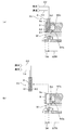
この基板処理装置は、中空の回転軸1が、モータ3の回転軸に連結されており、このモータ3の駆動により鉛直軸J周りに回転可能となっている。この回転軸1の上端部には、スピンベース5が一体的にネジなどの締結部品によって連結されている。したがって、モータ3の駆動によりスピンベース5が鉛直軸J周りに回転可能となっている。また、スピンベース5の周縁部付近には、基板Wの下面周縁部に当接しつつ基板Wを支持する支持部7が複数個、スピンベース5から上方に向けて突出して設けられている。そして、複数個の支持部7によってスピンベース5から所定の間隔離間させた状態で基板Wが水平に支持されている。このように、この実施形態ではスピンベース5が本発明の「回転部材」に相当している。
In this substrate processing apparatus, a hollow
図3は、スピンベース5を上方から見た平面図である。スピンベース5は基板Wと相似の円形で、その中心部に開口が設けられるとともに、その周縁部付近には支持部7が複数個(この実施形態では12個)設けられている。そして、12個の支持部7が鉛直軸Jを中心として30度ずつの等角度間隔で放射状に配置されている。ここで、基板Wを水平支持するためには、支持部7の個数は少なくとも3個以上であればよいが、支持部7が基板Wの下面に当接する部分を処理するためには、支持部7を基板Wの下面に対して離当接自在に構成するとともに、処理中に少なくとも1回以上、支持部7を基板Wの下面から離間させるのが望ましい。そのため、支持部7が基板Wの下面に当接する部分をも含めて基板Wの下面を処理するためには少なくとも4個以上の支持部7が必要とされる。なお、支持部7の構成および動作については後で詳述する。
FIG. 3 is a plan view of the
また、この基板処理装置は、図1に示すようにスピンベース5に対向して配置され、基板Wの上面側の雰囲気を遮断するための雰囲気遮断板9と、該雰囲気遮断板9と基板Wの上面との間に形成される空間に窒素ガス等の不活性ガスを供給するガス供給部21(本発明の「気体供給部」に相当)を備えている。そして、ガス供給部21から基板Wの上面に向けて雰囲気遮断板9と基板Wの上面との間に形成される空間に不活性ガスを供給することによって、基板Wを支持部7に押圧させて基板Wをスピンベース5に保持させることが可能となっている。
In addition, as shown in FIG. 1, the substrate processing apparatus is disposed so as to face the
この雰囲気遮断板9は、中空を有する筒状の支持軸11の下端部に一体回転可能に取り付けられている。この支持軸11には、図示を省略する遮断駆動機構が連結されており、遮断駆動機構のモータを駆動することにより支持軸11とともに雰囲気遮断板9が鉛直軸J周りに回転されるように構成されている。また、遮断駆動機構の昇降駆動用アクチュエータ(例えばエアシリンダーなど)を作動させることで雰囲気遮断板9をスピンベース5に近接させたり、逆に離間させることが可能となっている。このように、この実施形態ではモータ3と遮断駆動機構のモータとで本発明の「回転手段」が構成されている。
The
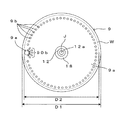
図4は雰囲気遮断板9の底面図である。この雰囲気遮断板9の基板Wの上面と対向する面の平面サイズD1は基板Wの平面サイズD2より若干大きく、その中心部に開口を有している。また、雰囲気遮断板9の周縁部には雰囲気遮断板9を上下方向(鉛直軸方向)に貫通する貫通孔9eが1個形成されており、後述するノズル6が挿入可能となっている。この貫通孔9eはスピンベース5に保持される基板Wの上面周縁部TR(図1)に対向する位置に形成されているため、ノズル6を貫通孔9eに挿入させることでノズル6を基板Wの上面周縁部TRに対向して配置させることができる。なお、貫通孔9eの孔径は、ノズル6が挿入可能な範囲で必要最小限の大きさで形成される。これは、必要以上に貫通孔9eの孔径を大きくすることで、貫通孔9eに起因する処理液の跳ね返り等の不具合を防止するためである。
FIG. 4 is a bottom view of the
雰囲気遮断板9はスピンベース5の上方に配置されて、その下面(底面)が基板Wの上面と対向する対向面9aとなっている。対向面9aには複数のガス噴出口9b、90bが開口している。ここで、ガス噴出口9bはスピンベース5に設けられた支持部7に対応する位置に、詳しくは支持部7の回転軌跡Ta(図3)上に鉛直軸Jを中心とする円周に沿って等間隔に配列されている。また、ガス噴出口90bは、貫通孔9eに対して雰囲気遮断板9の中心軸(鉛直軸J)よりに、貫通孔9eを取り囲むように配置されている。なお、これらのガス噴出口9b、90bは複数の開口にすることに限らず、例えば、複数のガス噴出口9b(または90b)のそれぞれを繋ぎ合わせて単一の開口としてもよい。さらに、複数のガス噴出口9b、90bの全てを繋ぎ合わせて全周にわたってリング状の開口としてもよい。但し、複数の開口とした方が、ガス噴出圧の均一性を得る点で有利である。このように、この実施形態では雰囲気遮断板9が本発明の「遮断部材」に、ガス噴出口9b、90bが本発明の「気体噴出口」に相当している。
The
図1に戻って説明を続ける。これらのガス噴出口9b、90bはそれぞれに、雰囲気遮断板9の内部に形成されたガス流通空間9c、90cに連通している。このガス流通空間9c、90cに不活性ガスを供給するために、ガス流通空間9c、90cは配管25を介してガス供給部21に連通接続されている。この配管25には、装置全体を制御する制御部80により開閉制御される開閉弁23が介装されている。このため、制御部80が開閉弁23を開にすることでガス供給部21からガス流通空間9c、90cに不活性ガスが供給されて、複数のガス噴出口9b、90bから基板Wの上面に向けて不活性ガスが噴出される。また、複数のガス噴出口9b、90bは支持部7の回転軌跡Ta上に配置されるように雰囲気遮断板9の対向面9aに設けられており、ガス噴出口9bは基板Wの上面側へ向けて略鉛直方向に不活性ガスを噴出するように形成される一方、ガス噴出口90bは基板Wの上面側へ向けて下向きかつ径方向外向きに噴出するように形成されている。そして、これらのガス噴出口9b、90bの各々から均一に不活性ガスが噴出されることで、基板Wはスピンベース5に上方に向けて突出して設けられた各支持部7に均等に押圧される。これにより、基板Wはスピンベース5に水平に保持される。ここで、基板Wの下面に支持部7が当接する部分に対応する基板Wの上面側に直接に不活性ガスを供給しているので、基板Wをスピンベース5に確実に、しかも必要最小限のガス供給量で効率良く保持させることができる。
Returning to FIG. 1, the description will be continued. These
次に、ノズル6の構成および動作について説明する。このノズル6は貫通孔9eの形状に合わせて円筒形状に構成され、貫通孔9eに挿入されることで、ノズル6の先端部が基板Wの上面周縁部TRに対向して配置される。また、ノズル6の先端部の下端面は雰囲気遮断板9の対向面9aと面一の位置まで挿入される。このため、ノズル6から基板Wの上面周縁部TRに処理液を供給可能になっている。すなわち、ノズル6には、その内部に薬液供給管61とリンス液供給管63が配設され、各供給管61、63の先端部(下端部)から基板Wの上面周縁部に対して、それぞれ薬液、リンス液として純水を供給できるように構成されている。ここで、薬液供給管61は配管14を介して薬液供給源31と接続される一方、リンス液供給管63が配管22を介して純水供給源33と接続されている。また、配管14、22にはそれぞれ、開閉弁16、20が介装されており、制御部80が開閉弁16、20を制御することでノズル6に供給される薬液および純水の流量を調整可能となっている。
Next, the configuration and operation of the
また、ノズル6は1本のアーム65(図2)の先端側に固着されている。一方、アーム65の基端部には、ノズル移動機構67が連結されている。そして、制御部80からの制御指令に応じてノズル移動機構67が作動することでアーム65を昇降駆動させるとともに、回転軸心P回りに揺動駆動させることが可能となっている。これにより、ノズル6は、雰囲気遮断板9の貫通孔9eに挿入されることで基板Wと対向して基板Wの上面周縁部TRに処理液を供給可能な対向位置P1(図1、図2の実線で示す位置)と、対向位置P1から上昇して側方に退避した退避位置P2(図1、図2の破線で示す位置)との間を移動することができる。このように、この実施形態ではノズル移動機構67が本発明の「ノズル駆動機構」に相当している。
The
また、雰囲気遮断板9の貫通孔9eの内壁にはガス導入口9dが設けられており、ガス導入口9dはガス流通空間90cに接続されている。このため、ガス供給部21から不活性ガスが供給されると、ガス噴出口9b、90bから基板Wの上面に向けて不活性ガスが噴出されると同時に、貫通孔9eの内部空間にも不活性ガスが導入される。したがって、ノズル6が退避位置P2に位置決めされる状態、すなわち、ノズル6が貫通孔9eに挿入されていない状態では、ガス供給部21から貫通孔9eに不活性ガスが導入され、雰囲気遮断板9の上下の貫通孔9eの開口から不活性ガスが噴出される。
A
雰囲気遮断板9の中心の開口および支持軸11の中空部には、上部洗浄ノズル12が同軸に設けられ、その下端部のノズル口12aからスピンベース5に押圧保持された基板Wの上面の回転中心付近に薬液、純水等の処理液を供給できるように構成されている。この上部洗浄ノズル12は、配管13に連通接続されている。この配管13は、基端部において分岐しており、一方の分岐配管13aには薬液供給源31が接続され、他方の分岐配管13bには純水供給源33が接続されている。各分岐配管13a、13bには開閉弁15、17が介装されており、制御部80による開閉弁15、17の開閉制御によって上部洗浄ノズル12から基板Wの上面に薬液と純水とを選択的に切換えて供給することができる。
An
また、支持軸11の中空部の内壁面と、上部洗浄ノズル12の外壁面との間の隙間は、気体供給路18となっている。この気体供給路18は、開閉弁19を介装した配管27を介して気体供給源35に連続接続されている。そして、上部洗浄ノズル12による薬液処理およびリンス処理を行った後、制御部80による開閉弁19の開閉制御によって気体供給路18を介して基板Wの上面と雰囲気遮断板9の対向面9aとの間の空間に清浄な空気や不活性ガス等の気体を供給することによって、基板Wの乾燥処理を行うことが可能となっている。
Further, a gap between the inner wall surface of the hollow portion of the
回転軸1の中空部には、下部洗浄ノズル41が同軸に設けられ、その上端部のノズル口41aから基板Wの下面の回転中心付近に処理液を供給できるように構成されている。この下部洗浄ノズル41は、配管43に連通接続されている。この配管43は、基端部において分岐しており、一方の分岐配管43aには薬液供給源31が接続され、他方の分岐配管43bには純水供給源33が接続されている。各分岐配管43a、43bには開閉弁45、47が介装されており、制御部80による開閉弁45、47の開閉制御によって下部洗浄ノズル41から基板Wの下面に薬液と純水とを選択的に切換えて供給することができる。
A
また、回転軸1の内壁面と下部洗浄ノズル41の外壁面との間の隙間は、円筒状の気体供給路48を形成している。この気体供給路48は、開閉弁49を介装した配管51を介して気体供給源35に連続接続されていて、制御部80による開閉弁49の開閉制御によって気体供給路48を介して基板Wの下面とスピンベース5の対向面との間の空間に清浄な空気や不活性ガス等の気体を供給することができる。
Further, a gap between the inner wall surface of the
次に、支持部7の構成および動作について説明する。図5は支持部の構成を示す部分断面図である。なお、上記複数の支持部7はいずれも同一構成を有しているため、ここではひとつの支持部7の構成についてのみ図面を参照しつつ説明する。図5に示すように、支持部7はスピンベース5の一部が上方に向けて凸状に延出した延出部5aの内部に設けられている。この支持部7は、基板Wの下面周縁部に離当接可能にスピンベース5の延出部5aの上面に埋設されたフィルム71と、上下方向に移動可能に支持されてフィルム71の下面側に開口した円筒状凹部の上底面に離当接してフィルム71の上面中央部を押上可能となっている可動ロッド73と、この可動ロッド73を上下動させるモータ等の駆動部75とを備えている。なお、駆動部75にはモータに限らず、エアシリンダ等のアクチュエータ全般を用いてもよい。
Next, the configuration and operation of the
上記した構成を有する支持部7では、駆動部75が制御部80からの駆動信号によって図示省略する駆動連結部を介して可動ロッド73を上昇駆動させることにより、可動ロッド73の先端部がフィルム71の円筒状凹部の上底面に当接してそのままフィルム71の上面中央部を押上げる。これにより、スピンベース5の上面側に埋設されているフィルム71の上面がスピンベース5の延出部5aの上面から突出する。このため、複数の支持部7のフィルム71の全て(若しくは少なくとも3個以上)を突出させることで、フィルム71を基板Wの下面と当接させつつ基板Wをスピンベース5の延出部5aの上面から離間(例えば、1mm程度)させて水平支持することが可能となる(図5)。一方で、駆動部75が可動ロッド73を下降駆動させると、可動ロッド73の先端部はフィルム71の円筒状凹部の上底面から離間されて、フィルム71の上面をスピンベース5の延出部5aの上面と同一平面内に収容する。このため、突出させた複数の支持部7のフィルム71のうち少なくとも3個を残して、その一部を下降させることで、下降させたフィルム71を基板Wの下面から離間させることが可能となる。なお、このようなフィルム71は、可撓性を有するとともに処理液に対する耐腐食性を有する樹脂により成形される。好ましくは、PCTFE(ポリクロロトリフルオロエチレン)等のフッ素樹脂が用いられる。このように、この実施形態ではフィルム71が本発明の「支持部材」に相当している。
In the
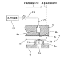
ここで、基板Wの上面周縁部にノズル6から処理液を供給して基板Wの上面処理領域TRを処理(ベベル処理)する場合における、上面処理領域TRと、雰囲気遮断板9の対向面9aに設けられたガス噴出口9b、90bから噴出される不活性ガスの供給位置および支持部7の配設位置との位置関係について説明する。図5は、ガス噴出口9bからの不活性ガスの供給位置および支持部7の配設位置との位置関係について図示しているが、ガス噴出口90bからの不活性ガスの供給位置および支持部7の配設位置との位置関係についても基本的に同様である。すなわち、ガス噴出口9bから基板Wの上面に向けて略鉛直方向に噴出される不活性ガスならびにガス噴出口90bから基板Wの上面に向けて下向きかつ径方向外向きに噴出される不活性ガスは、ノズル6からの処理液によって処理される上面処理領域TRより内側の非処理領域NTRに供給される。一方で、支持部7は不活性ガスが供給される非処理領域NTRに対応する基板Wの下面側に当接して支持するようにスピンベース5の周縁部に設けられている。このように構成することで基板Wをスピンベース5に押圧保持させるとともに、処理液の非処理領域NTRへの侵入を防止して基板Wの径方向における周端面からの処理幅を均一にすることができる。特にノズル6が挿入される貫通孔9eの周囲のガス噴出口90bからは、不活性ガスが基板Wの上面に向けて下向きかつ径方向外向きに噴出されるので、ノズル6から吐出される処理液が非処理領域NTRに入り込むのが確実に防止される。
Here, when the processing liquid is supplied from the
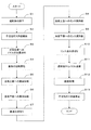
次に、上記のように構成された基板処理装置の動作について図6を参照しつつ詳述する。図6は、図1の基板処理装置の動作を示すフローチャートである。具体的には基板Wの下面側に処理液を供給して基板Wの下面を処理するとともに、基板Wの上面側に処理液を供給して基板Wの上面周縁部TRを処理する場合について説明する。この基板処理装置では、図示を省略する基板搬送ロボットにより未処理の基板Wが基板処理装置に搬送され、デバイス形成面を上にして裏面側で支持部7上に載置されると、制御部80が装置各部を以下のように制御して薬液処理、リンス処理、および乾燥処理を実行する。なお、基板搬送ロボットによる基板Wの搬送を行う際には、雰囲気遮断板9、支持軸11および上部洗浄ノズル12は一体的にスピンベース5の上方に離間退避している。
Next, the operation of the substrate processing apparatus configured as described above will be described in detail with reference to FIG. FIG. 6 is a flowchart showing the operation of the substrate processing apparatus of FIG. Specifically, the case where the processing liquid is supplied to the lower surface side of the substrate W to process the lower surface of the substrate W and the processing liquid is supplied to the upper surface side of the substrate W to process the upper surface peripheral portion TR of the substrate W will be described. To do. In this substrate processing apparatus, when an unprocessed substrate W is transported to the substrate processing apparatus by a substrate transport robot (not shown) and placed on the
上記のようにして基板Wが支持部7に載置されると、雰囲気遮断板9、支持軸11および上部洗浄ノズル12を一体的に降下させて雰囲気遮断板9を基板Wに近接配置させる(ステップS1)。これにより、基板Wの上面(デバイス形成面)は雰囲気遮断板9の対向面9aによって、ごく近接した状態で塞がれることになる。そして、開閉弁23を開にしてガス供給部21からの不活性ガスを雰囲気遮断板9の対向面9aに設けられた複数のガス噴出口9b、90bから噴出させることで、基板Wは支持部7に押圧され、スピンベース5に保持される(ステップS2)。ここで、複数のガス噴出口9b、90bから均等に不活性ガスを噴出させることで、基板Wは各支持部7に均等に押圧されて水平支持される。
When the substrate W is placed on the
次に、制御部80はノズル移動機構67を作動させることで、図7(a)に示すようにノズル6を雰囲気遮断板9の貫通孔9eに挿入させて対向位置P1に位置決めする(ステップS3)。それに続いて、制御部80は雰囲気遮断板9を停止させたままでモータ3を駆動してスピンベース5と一体に基板Wを回転させる(ステップS4)。支持部7に押圧された基板Wは支持部7と基板Wとの間に発生する摩擦力で支持部7に支持されながら、スピンベース5とともに回転することとなる。続いて、開閉弁16を開にしてノズル6から薬液を基板Wの上面周縁部TRに供給する(ステップS5)。これにより、薬液は基板Wの上面周縁部TRの全周にわたって基板Wの周端面から所定幅に均一に供給され、基板Wの上面周縁部TRに対する薬液処理が行われる。
Next, the
基板Wの上面周縁部TRへの薬液供給後、制御部80は開閉弁45を開にして薬液供給源31からの薬液を下部洗浄ノズル41のノズル口41aから基板Wの下面中心部に向けて供給する(ステップS6)。これにより、基板Wの下面中心部に供給された薬液は、基板Wの回転に伴う遠心力によって下面全体に拡がり、基板Wの下面全面に対する薬液処理が行われる。ここで、薬液処理中に各支持部7を基板Wの下面から少なくとも1回以上、離間させることで支持部7と基板Wの当接部分にも薬液を回り込ませて当該部分を処理することができる。この場合、例えば、12個の支持部7を順に1個ずつ離間させるようにしてもよいし、少なくとも3個の支持部7を基板Wの下面に当接させる限りにおいて2個以上の支持部7を一度に離間させるようにしてもよい。なお、基板Wの下面中心部における下部洗浄ノズル41のノズル口41aからの薬液の噴射圧に対抗させるために、気体供給路18からも不活性ガスを供給して基板Wを支持部7に押圧させるようにしてもよい。さらに、基板Wの下面に対する薬液処理は基板Wの上面周縁部TRに対する薬液処理中に、または基板Wの上面周縁部TRに対する薬液処理のタイミングと一部が重複するように行うようにしてもよい。こうして、薬液処理を所定時間行った後、基板Wの回転を継続しつつ、制御部80は開閉弁16、45を閉にして薬液供給源31からの薬液の供給を停止して薬液を振り切って基板外に排液する。
After supplying the chemical solution to the upper surface peripheral portion TR of the substrate W, the
ここで、ノズル6は雰囲気遮断板9の貫通孔9eに挿入されているため、薬液が飛散してノズル6に向けて跳ね返ってくるような場合でも薬液は雰囲気遮断板9の対向面9aに遮られ、ノズル6の周囲(側面)に薬液が付着するようなことはない。このため、ノズル移動時においてノズル6から薬液が落ちて基板Wあるいは基板周辺部材に付着して悪影響を及ぼすことが防止される。したがって、ノズル6の洗浄も不要となり、装置のスループットの向上を図ることができる。
Here, since the
また、基板Wの上面周縁部TRおよび下面に供給された薬液は基板Wの径方向外側に飛散するが、この実施形態では基板Wの外周端部を保持するチャックピン等の保持部材がないことから、基板Wの径方向外側に向かう薬液が基板表面に跳ね返ってくることがない。また、基板Wの外周端部付近の気流を乱す要因がないことから処理液ミストの基板表面側への巻き込みが軽減される。このため、基板Wの上面の非処理領域NTRに薬液が跳ね返って、デバイス形成面が腐食されるのを防止することができる。また、処理液ミストの巻き込みを防止することで基板表面へのパーティクル付着を抑制することができる。 Further, the chemical solution supplied to the upper surface peripheral portion TR and the lower surface of the substrate W is scattered outward in the radial direction of the substrate W, but in this embodiment, there is no holding member such as a chuck pin for holding the outer peripheral end portion of the substrate W. Therefore, the chemical solution directed toward the outer side in the radial direction of the substrate W does not rebound to the substrate surface. In addition, since there is no factor that disturbs the airflow near the outer peripheral edge of the substrate W, the entrainment of the processing liquid mist on the substrate surface side is reduced. For this reason, it is possible to prevent the chemical solution from splashing back into the non-processing region NTR on the upper surface of the substrate W and corroding the device formation surface. Further, by preventing the treatment liquid mist from being caught, the adhesion of particles to the substrate surface can be suppressed.
こうして、薬液の液切りが完了すると(ステップS7)、制御部80は開閉弁20を開にして、ノズル6からリンス液(純水、DIW等)を基板Wの上面周縁部TRに供給する(ステップS8)。これにより、基板Wの上面周縁部TRに付着している薬液がリンス液で洗い落とされる。また、基板Wの下面に対しても、基板Wの上面周縁部TRに対するリンス処理後に、または基板Wの上面周縁部TRに対するリンス処理中に、または基板Wの上面周縁部TRに対するリンス処理のタイミングと一部が重複するように、制御部80は開閉弁47を開にすることでリンス処理を行う(ステップS9)。そして、リンス処理を所定時間行った後、制御部80は開閉弁20、47を閉にしてリンス液の供給を停止してリンス液を振り切って基板外に排液する(ステップS10)。
Thus, when the draining of the chemical solution is completed (step S7), the
次に、制御部80はノズル移動機構67を作動させることで、図7(b)に示すようにノズル6を貫通孔9eから抜き出して雰囲気遮断板9から離れた退避位置P2に位置決めする(ステップS11)。そして、モータ3を高速回転させることで、基板Wの回転が加速され、基板Wの乾燥処理が行われる(ステップS12)。これにより、基板表面に付着する液成分が遠心力で振り切られる。このとき、図示を省略する遮断駆動機構のモータを駆動させることにより支持軸11とともに雰囲気遮断板9を鉛直軸J周りに回転させることで、スピンドライを効果的に行うことができる。また、このように基板Wとともに雰囲気遮断板9を回転させることで基板Wと雰囲気遮断板9との間に回転に伴う余分な気流が発生するのを防止することができる。この乾燥処理の間、制御部80は開閉弁49を開にして気体供給源35から所定流量の不活性ガスを基板Wの下面とスピンベース5の対向面との間の空間に導入するとともに、開閉弁19を開にして所定流量の不活性ガスを基板Wの上面と雰囲気遮断板9の対向面9aとの間の空間に導入する。その結果、基板Wを取り囲む周囲の空間は速やかに不活性ガスによって置換されるので、空間内に残留する薬液雰囲気によって基板Wが汚染されることがない。また、不所望な酸化膜が基板Wの上下面に成長することがない。
Next, the
また、ノズル6が退避位置P2に位置決めされ、ノズル6が貫通孔9eから抜き出されると、ガス導入口9dから貫通孔9eに導入される不活性ガスが雰囲気遮断板9の上下の貫通孔9eの開口から勢いよく噴出する(図7(b))。このため、ノズル6が貫通孔9eから抜き出された状態であっても、リンス液が貫通孔9eに入り込み基板Wに向けて跳ね返ることがない。したがって、貫通孔9eに起因する跳ね返りが抑制され、基板Wの上面中央部(非処理領域NTR)に形成されるデバイス形成面を腐食させることがない。
When the
乾燥処理が終了した後、制御部80はモータ3の駆動を停止させて基板Wの回転を停止させるとともに、遮断駆動機構のモータを停止させて雰囲気遮断板9の回転を停止させる。そして、開閉弁23を閉にしてガス供給部21からのガス供給を停止することで、基板Wの押圧支持を解除する(ステップS13)。その後、雰囲気遮断板9が上方へ移動させられ、基板搬送ロボットによって処理済の基板Wが搬出される。これにより、一連の薬液処理およびリンス処理の動作が終了する。
After the drying process is completed, the
以上のように、この実施形態によれば、雰囲気遮断板9の平面サイズD1は基板サイズD2に対して同等以上の大きさであるので、該雰囲気遮断板9を基板Wの上面に対向して配設することで、基板Wの上面が基板周囲の外部雰囲気から確実に遮断される。また、雰囲気遮断板9の周縁部にはノズル6が挿入可能な貫通孔9eが形成されているので、ノズル6を該貫通孔9eに挿入させることで基板Wの上面周縁部TRと対向して配置させることができる。このため、スピンベース5に保持された基板Wを回転させるとともに、ノズル6から処理液を供給することで、基板Wの上面周縁部TRの全周に渡って直接に処理液を供給することができる。したがって、基板Wの上面全体を雰囲気遮断板9で覆うことで基板Wの上面中央部(非処理領域NTR)へ処理液が付着するのを防止しながら、基板Wの径方向における周端面からの処理幅を均一にして処理することができる。
As described above, according to this embodiment, since the plane size D1 of the
特に、基板Wの下面に供給される処理液を基板Wの周端面から回り込ませて基板Wの上面周縁部TRの処理を行う場合に比べて、基板Wの径方向における周端面からの処理幅の制御が容易であり、処理幅を高精度に制御することができるとともに、処理幅を大きくすることも可能である。また、半導体ウエハ等の基板Wにノッチ部分がある場合でも、ノッチ部分の処理幅の均一性を良好にすることができる。 In particular, the processing width supplied from the peripheral end surface in the radial direction of the substrate W compared to the case where the processing liquid supplied to the lower surface of the substrate W is made to circulate from the peripheral end surface of the substrate W to perform processing on the upper peripheral edge TR of the substrate W. The processing width can be easily controlled, the processing width can be controlled with high accuracy, and the processing width can be increased. Even when the substrate W such as a semiconductor wafer has a notch portion, the uniformity of the processing width of the notch portion can be improved.
また、この実施形態によれば、ノズル6を雰囲気遮断板9とは離れた退避位置P2に位置決めすることで、基板Wとともに雰囲気遮断板9を回転させることができる。このため、雰囲気遮断板9に付着する処理液を振り切るとともに、基板Wと雰囲気遮断板9との間に回転に伴う余分な気流が発生するのを防止することができ、より良好な基板処理を行うことができる。
In addition, according to this embodiment, the
また、この実施形態によれば、ノズル6は貫通孔9eに挿入されているため、基板処理中に処理液が飛散してノズル6に向けて跳ね返ってくるような場合でも、処理液は雰囲気遮断板9の対向面9aに遮られてノズル6に大量の処理液が付着することがない。このため、ノズル移動時においてノズル6から処理液が落ちて基板Wあるいは基板周辺部材に付着して悪影響を及ぼすことが防止される。その結果、ノズル6の洗浄も不要となり、装置のスループットを向上させることができる。
In addition, according to this embodiment, since the
また、この実施形態によれば、ノズル6が雰囲気遮断板9から離れた退避位置P2に位置決めされる際にも、貫通孔9eの上下の開口から不活性ガスが噴出されているので、処理液が貫通孔9eに入り込み基板Wに処理液が跳ね返ることがない。このため、貫通孔9eに起因する処理液の跳ね返りによって基板Wの上面中央部(非処理領域NTR)に形成されるデバイス形成面を腐食させることがない。
Further, according to this embodiment, when the
また、この実施形態によれば、ノズル6を貫通孔9eから抜き出すと同時に貫通孔9eから不活性ガスが噴出されるので、不活性ガスの供給を効率良く行うことができる。また、ガス流通空間9cからの不活性ガスをガス導入口9dを介して貫通孔9eに導入しているので、基板Wをスピンベース5に押圧保持させるためのガス供給部21および配管25などを共通利用できるため装置構成を簡略化することができる。
Moreover, according to this embodiment, since the inert gas is ejected from the through-
さらに、この実施形態によれば、基板Wは、その下面に当接する支持部7に離間して支持されるとともに、その上面に供給される不活性ガスによって支持部7に押圧されることで、スピンベース5に保持される。そして、基板Wは支持部7との間に発生する摩擦力で支持部7に支持されてスピンベース5とともに回転される。このように基板Wを保持することで、基板Wの外周端部に接触して基板Wを保持するチャックピン等の保持部材を不要とすることができる。このため、基板Wの回転により基板表面を伝って径方向外側に向かう処理液が直接にチャックピン等の保持部材に当たって基板表面へ跳ね返ることがない。また、基板Wの外周端部付近の気流を乱す要因がないことからミスト状の処理液の基板表面側への巻き込みを軽減することができる。これにより、基板の上面中央部(非処理領域NTR)への処理液の付着を効果的に防止することができる。
Furthermore, according to this embodiment, the substrate W is supported by being separated from the
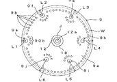
なお、本発明は上記した実施形態に限定されるものではなく、その趣旨を逸脱しない限りにおいて上述したもの以外に種々の変更を行うことが可能である。例えば、上記実施形態では、雰囲気遮断板9の周縁部に1箇所の貫通孔9eを形成しているが、これに限定されない。例えば、図8に示すように、雰囲気遮断板9の周縁部に複数箇所の貫通孔を形成するようにしてもよい。図8では、6箇所の貫通孔9e〜9jを形成した場合の雰囲気遮断板9の底面図を示している。このとき、各貫通孔の雰囲気遮断板9の周端面からの距離を異ならせることにより、例えば、貫通孔9e〜9jの雰囲気遮断板9の周端面からの距離L1〜L6をL1<L2<L3<L4<L5<L6とすることにより、基板Wの径方向における周端面からの処理幅を変更することができる。すなわち、ノズル6を貫通孔9e〜9jに選択的に挿入させることで、処理内容に応じて適宜、基板Wの径方向における周端面からの処理幅を変更しながら、しかも均一にして処理することができる。なお、この実施形態においても、貫通孔9e〜9jから不活性ガスを噴出させることで、貫通孔9e〜9jに起因する処理液の跳ね返りを防止することができる。
The present invention is not limited to the above-described embodiment, and various modifications other than those described above can be made without departing from the spirit of the present invention. For example, in the above embodiment, one through
また、上記実施形態では、ノズル6および貫通孔9eを円筒形状としているが、これに限定されない。例えば、ノズル先端部を先細りの形状(円錐台形状)にするとともに、貫通孔を該ノズル形状に合わせて形成するようにしてもよい。
Moreover, in the said embodiment, although the
この発明は、半導体ウエハ、フォトマスク用ガラス基板、液晶表示用ガラス基板、プラズマ表示用ガラス基板、光ディスク用基板などを含む基板全般の表面に対して洗浄処理などの処理を施す基板処理装置に適用することができる。 The present invention is applied to a substrate processing apparatus for performing a process such as a cleaning process on the entire surface of a substrate including a semiconductor wafer, a glass substrate for a photomask, a glass substrate for a liquid crystal display, a glass substrate for a plasma display, and an optical disk substrate. can do.
3…モータ(回転手段)
5…スピンベース(回転部材)
6…ノズル
9…雰囲気遮断板(遮断部材)
9a…対向面
9b、90b…ガス噴出口(気体噴出口)
9d…ガス導入口(気体導入口)
9e〜9j…貫通孔
21…ガス供給部(気体供給部)
67…ノズル移動機構(ノズル駆動機構)
71…フィルム(支持部材)
J…鉛直軸
NTR…非処理領域
P1…対向位置
P2…退避位置
TR…上面処理領域(上面周縁部)
W…基板
3 ... Motor (rotating means)
5 ... Spin base (rotating member)
6 ...
9a ... Opposing
9d ... Gas inlet (gas inlet)
9e-9j ... through-
67 ... Nozzle movement mechanism (nozzle drive mechanism)
71 ... Film (supporting member)
J: Vertical axis NTR: Non-processing area P1: Opposing position P2: Retraction position TR: Upper surface processing area (upper edge portion)
W ... Board
Claims (11)
前記基板を保持する基板保持手段と、
前記基板保持手段により保持された基板を回転させる回転手段と、
回転する前記基板の上面周縁部に前記処理液を供給するノズルと、
前記基板の上面に対向して配設されるとともに、その周縁部に前記ノズルが挿入可能な上下方向に貫通する貫通孔を有する遮断部材と、
前記ノズルを駆動することで前記ノズルを前記貫通孔に挿入させて前記基板の上面周縁部に対向する対向位置と、前記遮断部材から離れた退避位置とに位置決めさせるノズル駆動機構と、
前記ノズルが前記退避位置に位置決めされた状態で、前記貫通孔から気体を噴出させる気体噴出手段と
を備え、
前記対向位置に位置決めされた前記ノズルから前記基板の上面周縁部に処理液を供給することを特徴とする基板処理装置。 In a substrate processing apparatus for performing a predetermined process by supplying a processing liquid to the substrate while rotating the substrate,
Substrate holding means for holding the substrate;
Rotating means for rotating the substrate held by the substrate holding means;
A nozzle for supplying the treatment liquid to the peripheral edge of the upper surface of the rotating substrate;
A blocking member that is disposed to face the upper surface of the substrate and has a through-hole penetrating in a vertical direction in which the nozzle can be inserted in a peripheral portion thereof;
A nozzle driving mechanism that drives the nozzle to position the nozzle in the through-hole so as to be positioned at a facing position facing the peripheral edge of the upper surface of the substrate and a retracted position away from the blocking member ;
In a state in which the nozzle is positioned in the retracted position, comprise a <br/> and gas ejection means for ejecting gas from the through hole,
A substrate processing apparatus, wherein a processing liquid is supplied from the nozzle positioned at the facing position to a peripheral edge of the upper surface of the substrate.
前記基板を保持する基板保持手段と、
前記基板保持手段により保持された基板を回転させる回転手段と、
回転する前記基板の上面周縁部に前記処理液を供給するノズルと、
前記基板の上面に対向して配設されるとともに、その周縁部に前記ノズルが挿入可能な上下方向に貫通する貫通孔を有する遮断部材と、
前記ノズルを駆動することで前記ノズルを前記貫通孔に挿入させて前記基板の上面周縁部に対向する対向位置と、前記遮断部材から離れた退避位置とに位置決めさせるノズル駆動機構と
を備え、
前記対向位置に位置決めされた前記ノズルから前記基板の上面周縁部に処理液を供給し、
前記ノズルが前記退避位置に位置決めされた状態で、前記回転手段は前記基板とともに前記遮断部材を回転させることを特徴とする基板処理装置。 In a substrate processing apparatus for performing a predetermined process by supplying a processing liquid to the substrate while rotating the substrate,
Substrate holding means for holding the substrate;
Rotating means for rotating the substrate held by the substrate holding means;
A nozzle for supplying the treatment liquid to the peripheral edge of the upper surface of the rotating substrate;
A blocking member that is disposed to face the upper surface of the substrate and has a through-hole penetrating in a vertical direction in which the nozzle can be inserted in a peripheral portion thereof;
A nozzle drive mechanism that drives the nozzle to insert the nozzle into the through hole and positions the nozzle at a facing position facing the peripheral edge of the upper surface of the substrate and a retracted position away from the blocking member;
Supplying a processing liquid from the nozzle positioned at the facing position to the peripheral edge of the upper surface of the substrate ;
The nozzle in a state of being positioned in the retracted position, said rotating means substrate processing apparatus according to claim Rukoto rotating the blocking member together with the substrate.
前記基板を保持する基板保持手段と、
前記基板保持手段により保持された基板を回転させる回転手段と、
回転する前記基板の上面周縁部に前記処理液を供給するノズルと、
前記基板の上面に対向して配設されるとともに、その周縁部に前記ノズルが挿入可能な上下方向に貫通する貫通孔を有する遮断部材と、
前記ノズルを駆動することで前記ノズルを前記貫通孔に挿入させて前記基板の上面周縁部に対向する対向位置と、前記遮断部材から離れた退避位置とに位置決めさせるノズル駆動機構と
を備え、
前記基板保持手段は、鉛直軸回りに回転自在に設けられた回転部材と、前記回転部材に上方に向けて設けられ、前記基板の下面に当接して該基板を前記回転部材から離間させて支持する少なくとも3個以上の支持部材と、前記遮断部材が前記基板上面と対向する対向面に設けられた気体噴出口から気体を前記対向面と前記基板上面との間に形成される空間に供給することによって前記基板を前記支持部材に押圧させる気体供給部とを備え、
前記対向位置に位置決めされた前記ノズルから前記基板の上面周縁部に処理液を供給することを特徴とする基板処理装置。 In a substrate processing apparatus for performing a predetermined process by supplying a processing liquid to the substrate while rotating the substrate,
Substrate holding means for holding the substrate;
Rotating means for rotating the substrate held by the substrate holding means;
A nozzle for supplying the treatment liquid to the peripheral edge of the upper surface of the rotating substrate;
A blocking member that is disposed to face the upper surface of the substrate and has a through-hole penetrating in a vertical direction in which the nozzle can be inserted in a peripheral portion thereof;
A nozzle drive mechanism that drives the nozzle to insert the nozzle into the through hole and positions the nozzle at a facing position facing the peripheral edge of the upper surface of the substrate and a retracted position away from the blocking member;
The substrate holding means is provided so as to be rotatable about a vertical axis, and is provided on the rotating member so as to face upward. The substrate holding means abuts on the lower surface of the substrate and supports the substrate apart from the rotating member. The gas is supplied to a space formed between the facing surface and the upper surface of the substrate from at least three support members and a gas outlet provided on the facing surface where the blocking member faces the upper surface of the substrate. A gas supply unit that presses the substrate against the support member.
A substrate processing apparatus, wherein a processing liquid is supplied from the nozzle positioned at the facing position to a peripheral edge of the upper surface of the substrate.
前記気体噴出手段は前記気体供給部から供給される気体を前記貫通孔の内壁に設けられた気体導入口から前記貫通孔内に導くことで前記気体を前記貫通孔から噴出させる請求項6記載の基板処理装置。 In a state where the nozzle is positioned at the retracted position, the nozzle further comprises gas ejection means for ejecting gas from the through hole,
Said gas ejection means according to claim 6, wherein the jetting the gas from the through hole by directing the gas supplied from the gas supply unit from the gas inlet port provided on an inner wall of the through hole in the through-hole Substrate processing equipment.
前記基板を保持する基板保持手段と、
前記基板保持手段により保持された基板を回転させる回転手段と、
回転する前記基板の上面周縁部に前記処理液を供給するノズルと、
前記基板の上面に対向して配設されるとともに、その周縁部に前記ノズルが挿入可能な上下方向に貫通する貫通孔を有する遮断部材と、
前記ノズルを駆動することで前記ノズルを前記貫通孔に挿入させて前記基板の上面周縁部に対向する対向位置と、前記遮断部材から離れた退避位置とに位置決めさせるノズル駆動機構と
を備え、
前記対向位置に位置決めされた前記ノズルから前記基板の上面周縁部に処理液を供給し、
前記遮断部材は前記貫通孔を複数個有するものであって、各貫通孔の前記遮断部材の周端面からの径方向における距離が互いに異なることを特徴とする基板処理装置。 In a substrate processing apparatus for performing a predetermined process by supplying a processing liquid to the substrate while rotating the substrate,
Substrate holding means for holding the substrate;
Rotating means for rotating the substrate held by the substrate holding means;
A nozzle for supplying the treatment liquid to the peripheral edge of the upper surface of the rotating substrate;
A blocking member that is disposed to face the upper surface of the substrate and has a through-hole penetrating in a vertical direction in which the nozzle can be inserted in a peripheral portion thereof;
A nozzle drive mechanism that drives the nozzle to insert the nozzle into the through hole and positions the nozzle at a facing position facing the peripheral edge of the upper surface of the substrate and a retracted position away from the blocking member;
Supplying a processing liquid from the nozzle positioned at the facing position to the peripheral edge of the upper surface of the substrate ;
The said blocking member has a plurality of said through-holes, The distance in the radial direction from the peripheral end surface of the said blocking member of each through-hole is mutually different, The substrate processing apparatus characterized by the above-mentioned .
Priority Applications (4)
| Application Number | Priority Date | Filing Date | Title |
|---|---|---|---|
| JP2004223412A JP4397299B2 (en) | 2004-07-30 | 2004-07-30 | Substrate processing equipment |
| TW094116824A TWI258185B (en) | 2004-07-30 | 2005-05-24 | Substrate processing apparatus and method |
| US11/154,363 US7722736B2 (en) | 2004-07-30 | 2005-06-16 | Apparatus for and method of processing a substrate with processing liquid |
| CN2005100786509A CN1727081B (en) | 2004-07-30 | 2005-06-21 | Apparatus for and method of processing a substrate |
Applications Claiming Priority (1)
| Application Number | Priority Date | Filing Date | Title |
|---|---|---|---|
| JP2004223412A JP4397299B2 (en) | 2004-07-30 | 2004-07-30 | Substrate processing equipment |
Publications (3)
| Publication Number | Publication Date |
|---|---|
| JP2006041444A JP2006041444A (en) | 2006-02-09 |
| JP2006041444A5 JP2006041444A5 (en) | 2007-09-13 |
| JP4397299B2 true JP4397299B2 (en) | 2010-01-13 |
Family
ID=35730770
Family Applications (1)
| Application Number | Title | Priority Date | Filing Date |
|---|---|---|---|
| JP2004223412A Expired - Fee Related JP4397299B2 (en) | 2004-07-30 | 2004-07-30 | Substrate processing equipment |
Country Status (4)
| Country | Link |
|---|---|
| US (1) | US7722736B2 (en) |
| JP (1) | JP4397299B2 (en) |
| CN (1) | CN1727081B (en) |
| TW (1) | TWI258185B (en) |
Families Citing this family (56)
| Publication number | Priority date | Publication date | Assignee | Title |
|---|---|---|---|---|
| US20080017316A1 (en) * | 2002-04-26 | 2008-01-24 | Accretech Usa, Inc. | Clean ignition system for wafer substrate processing |
| US20070062647A1 (en) * | 2005-09-19 | 2007-03-22 | Bailey Joel B | Method and apparatus for isolative substrate edge area processing |
| US20080011332A1 (en) * | 2002-04-26 | 2008-01-17 | Accretech Usa, Inc. | Method and apparatus for cleaning a wafer substrate |
| US20080190558A1 (en) * | 2002-04-26 | 2008-08-14 | Accretech Usa, Inc. | Wafer processing apparatus and method |
| JP4262004B2 (en) * | 2002-08-29 | 2009-05-13 | 大日本スクリーン製造株式会社 | Substrate processing apparatus and substrate processing method |
| JP2005045206A (en) * | 2003-07-07 | 2005-02-17 | Dainippon Screen Mfg Co Ltd | Method and equipment for substrate processing |
| JP4446875B2 (en) * | 2004-06-14 | 2010-04-07 | 大日本スクリーン製造株式会社 | Substrate processing equipment |
| JP4698407B2 (en) * | 2005-12-20 | 2011-06-08 | 大日本スクリーン製造株式会社 | Substrate processing apparatus and substrate processing method |
| JP4907400B2 (en) * | 2006-07-25 | 2012-03-28 | 大日本スクリーン製造株式会社 | Substrate processing apparatus and substrate processing method |
| JP4708286B2 (en) * | 2006-08-11 | 2011-06-22 | 大日本スクリーン製造株式会社 | Substrate processing apparatus and substrate processing method |
| JP4679479B2 (en) * | 2006-09-28 | 2011-04-27 | 大日本スクリーン製造株式会社 | Substrate processing apparatus and substrate processing method |
| JP4762098B2 (en) * | 2006-09-28 | 2011-08-31 | 大日本スクリーン製造株式会社 | Substrate processing apparatus and substrate processing method |
| JP5090089B2 (en) * | 2006-10-19 | 2012-12-05 | 大日本スクリーン製造株式会社 | Substrate processing equipment |
| JP4936878B2 (en) * | 2006-12-25 | 2012-05-23 | 大日本スクリーン製造株式会社 | Substrate processing apparatus and substrate processing method |
| JP4841451B2 (en) | 2007-01-31 | 2011-12-21 | 大日本スクリーン製造株式会社 | Substrate processing apparatus and substrate processing method |
| JP4906559B2 (en) * | 2007-03-29 | 2012-03-28 | 大日本スクリーン製造株式会社 | Substrate processing apparatus and substrate processing method |
| US7958899B2 (en) | 2007-08-21 | 2011-06-14 | Dainippon Screen Mfg. Co., Ltd. | Substrate cleaning apparatus and substrate cleaning method |
| JP5242242B2 (en) * | 2007-10-17 | 2013-07-24 | 株式会社荏原製作所 | Substrate cleaning device |
| EP2051285B1 (en) * | 2007-10-17 | 2011-08-24 | Ebara Corporation | Substrate cleaning apparatus |
| US7879183B2 (en) * | 2008-02-27 | 2011-02-01 | Applied Materials, Inc. | Apparatus and method for front side protection during backside cleaning |
| KR101205460B1 (en) | 2008-06-05 | 2012-11-29 | 도쿄엘렉트론가부시키가이샤 | Liquid treatment apparatus and liquid treatment method |
| KR101065557B1 (en) | 2008-10-29 | 2011-09-19 | 다이닛뽕스크린 세이조오 가부시키가이샤 | Substrate treatment apparatus |
| JP5156661B2 (en) * | 2009-02-12 | 2013-03-06 | 東京エレクトロン株式会社 | Liquid processing apparatus and liquid processing method |
| JP5623104B2 (en) * | 2010-03-18 | 2014-11-12 | 東京エレクトロン株式会社 | Substrate cleaning apparatus and substrate cleaning method |
| JP5270607B2 (en) | 2010-03-30 | 2013-08-21 | 大日本スクリーン製造株式会社 | Substrate processing equipment |
| US8926788B2 (en) * | 2010-10-27 | 2015-01-06 | Lam Research Ag | Closed chamber for wafer wet processing |
| JP6131187B2 (en) * | 2011-06-30 | 2017-05-17 | Hoya株式会社 | Manufacturing method of glass substrate for HDD |
| JP5996381B2 (en) * | 2011-12-28 | 2016-09-21 | 東京エレクトロン株式会社 | Substrate processing apparatus and substrate processing method |
| JP5646528B2 (en) * | 2012-03-09 | 2014-12-24 | 東京エレクトロン株式会社 | Liquid processing equipment |
| US20130309874A1 (en) * | 2012-05-15 | 2013-11-21 | Lam Research Ag | Method and apparatus for liquid treatment of wafer-shaped articles |
| US10707099B2 (en) | 2013-08-12 | 2020-07-07 | Veeco Instruments Inc. | Collection chamber apparatus to separate multiple fluids during the semiconductor wafer processing cycle |
| US9768041B2 (en) | 2013-08-12 | 2017-09-19 | Veeco Precision Surface Processing Llc | Collection chamber apparatus to separate multiple fluids during the semiconductor wafer processing cycle |
| TWI569349B (en) | 2013-09-27 | 2017-02-01 | 斯克林集團公司 | Substrate processing apparatus and substrate processing method |
| TWI597770B (en) | 2013-09-27 | 2017-09-01 | 斯克林集團公司 | Substrate processing apparatus and substrate processing method |
| JP6338904B2 (en) * | 2014-03-24 | 2018-06-06 | 株式会社Screenホールディングス | Substrate processing equipment |
| CN104183524A (en) * | 2014-08-27 | 2014-12-03 | 上海华力微电子有限公司 | Wafer edge etching device |
| TWI661479B (en) * | 2015-02-12 | 2019-06-01 | 日商思可林集團股份有限公司 | Substrate processing apparatus, substrate processing system, and substrate processing method |
| US10730059B2 (en) | 2015-03-05 | 2020-08-04 | SCREEN Holdings Co., Ltd. | Substrate processing method and substrate processing apparatus |
| DE102015104735A1 (en) * | 2015-03-27 | 2016-09-29 | Obducat Ab | Turntable for receiving a substrate for a coating device |
| TWI661477B (en) * | 2015-06-18 | 2019-06-01 | 日商思可林集團股份有限公司 | Substrate processing apparatus |
| US9968970B2 (en) * | 2015-12-04 | 2018-05-15 | Lam Research Ag | Spin chuck with in situ cleaning capability |
| CN107437516B (en) | 2016-05-25 | 2021-07-13 | 株式会社斯库林集团 | Substrate processing apparatus and substrate processing method |
| JP6817821B2 (en) * | 2016-05-25 | 2021-01-20 | 株式会社Screenホールディングス | Substrate processing equipment and substrate processing method |
| CN106158709B (en) * | 2016-07-22 | 2018-09-11 | 江苏鲁汶仪器有限公司 | A kind of wafer cutting device and method |
| JP6885753B2 (en) * | 2017-03-08 | 2021-06-16 | 株式会社Screenホールディングス | Substrate processing equipment and substrate processing method |
| US11342215B2 (en) | 2017-04-25 | 2022-05-24 | Veeco Instruments Inc. | Semiconductor wafer processing chamber |
| JP6842391B2 (en) * | 2017-09-07 | 2021-03-17 | キオクシア株式会社 | Semiconductor manufacturing equipment and manufacturing method of semiconductor equipment |
| CN111107949B (en) * | 2017-12-18 | 2022-04-19 | 积水化学工业株式会社 | Surface treatment method and apparatus |
| CN108133906A (en) * | 2017-12-27 | 2018-06-08 | 德淮半导体有限公司 | Wafer processing apparatus and wafer processing |
| JP7218098B2 (en) * | 2018-05-31 | 2023-02-06 | 株式会社デンソーテン | Coating device and coating method |
| JP7166089B2 (en) * | 2018-06-29 | 2022-11-07 | 東京エレクトロン株式会社 | SUBSTRATE PROCESSING APPARATUS, SUBSTRATE PROCESSING SYSTEM AND SUBSTRATE PROCESSING METHOD |
| WO2020039849A1 (en) * | 2018-08-22 | 2020-02-27 | 東京エレクトロン株式会社 | Substrate treatment method and substrate treatment device |
| KR102154486B1 (en) * | 2018-10-11 | 2020-09-10 | 주식회사 테스 | Gas supply unit |
| CN111081585B (en) * | 2018-10-18 | 2022-08-16 | 北京北方华创微电子装备有限公司 | Spray device and cleaning equipment |
| CN113113328B (en) * | 2021-03-04 | 2023-01-31 | 江苏亚电科技有限公司 | Single wafer cleaning device washs dish structure and single wafer cleaning device |
| CN113539937B (en) * | 2021-07-09 | 2023-03-03 | 江西龙芯微科技有限公司 | Wafer bearing device |
Family Cites Families (15)
| Publication number | Priority date | Publication date | Assignee | Title |
|---|---|---|---|---|
| US20040065540A1 (en) * | 2002-06-28 | 2004-04-08 | Novellus Systems, Inc. | Liquid treatment using thin liquid layer |
| EP1091388A3 (en) * | 1999-10-06 | 2005-09-21 | Ebara Corporation | Method and apparatus for cleaning a substrate |
| JP3709129B2 (en) | 2000-08-29 | 2005-10-19 | 大日本スクリーン製造株式会社 | Substrate processing apparatus and substrate processing method |
| JP2002176020A (en) | 2000-09-04 | 2002-06-21 | Sony Corp | Apparatus and method for treating substrate as well as method for manufacturing device product |
| JP3958539B2 (en) * | 2001-08-02 | 2007-08-15 | 東京エレクトロン株式会社 | Substrate processing apparatus and substrate processing method |
| JP3727602B2 (en) | 2002-03-11 | 2005-12-14 | 大日本スクリーン製造株式会社 | Substrate peripheral processing apparatus and substrate peripheral processing method |
| JP2004006672A (en) | 2002-04-19 | 2004-01-08 | Dainippon Screen Mfg Co Ltd | Substrate processing method and apparatus |
| JP3838946B2 (en) * | 2002-07-22 | 2006-10-25 | 株式会社荏原製作所 | Substrate processing apparatus and substrate processing method |
| US20040084144A1 (en) * | 2002-08-21 | 2004-05-06 | Dainippon Screen Mfg. Co., Ltd. | Substrate processing apparatus and substrate processing method |
| KR100466297B1 (en) * | 2002-10-17 | 2005-01-13 | 한국디엔에스 주식회사 | Apparatus for manufacturing semiconductor devices |
| JP4446875B2 (en) * | 2004-06-14 | 2010-04-07 | 大日本スクリーン製造株式会社 | Substrate processing equipment |
| US7547181B2 (en) * | 2004-11-15 | 2009-06-16 | Dainippon Screen Mfg. Co., Ltd. | Substrate position correcting method and apparatus using either substrate radius or center of rotation correction adjustment sum |
| JP4222997B2 (en) * | 2004-11-15 | 2009-02-12 | 大日本スクリーン製造株式会社 | Substrate processing equipment |
| JP4698407B2 (en) * | 2005-12-20 | 2011-06-08 | 大日本スクリーン製造株式会社 | Substrate processing apparatus and substrate processing method |
| JP4708286B2 (en) * | 2006-08-11 | 2011-06-22 | 大日本スクリーン製造株式会社 | Substrate processing apparatus and substrate processing method |
-
2004
- 2004-07-30 JP JP2004223412A patent/JP4397299B2/en not_active Expired - Fee Related
-
2005
- 2005-05-24 TW TW094116824A patent/TWI258185B/en not_active IP Right Cessation
- 2005-06-16 US US11/154,363 patent/US7722736B2/en not_active Expired - Fee Related
- 2005-06-21 CN CN2005100786509A patent/CN1727081B/en not_active Expired - Fee Related
Also Published As
| Publication number | Publication date |
|---|---|
| TWI258185B (en) | 2006-07-11 |
| CN1727081A (en) | 2006-02-01 |
| JP2006041444A (en) | 2006-02-09 |
| TW200605209A (en) | 2006-02-01 |
| US7722736B2 (en) | 2010-05-25 |
| US20060021636A1 (en) | 2006-02-02 |
| CN1727081B (en) | 2011-06-08 |
Similar Documents
| Publication | Publication Date | Title |
|---|---|---|
| JP4397299B2 (en) | Substrate processing equipment | |
| JP4446875B2 (en) | Substrate processing equipment | |
| KR101375423B1 (en) | Apparatus for liquid treatment of treatment object | |
| JP4657090B2 (en) | Substrate processing equipment | |
| US6793769B2 (en) | Substrate processing apparatus | |
| KR100979979B1 (en) | Liquid processing apparatus and liquid processing method | |
| JP4619144B2 (en) | Substrate processing equipment | |
| JP4979758B2 (en) | Substrate processing apparatus and method | |
| JP7197376B2 (en) | Substrate processing method and substrate processing apparatus | |
| JP4222997B2 (en) | Substrate processing equipment | |
| JP6890992B2 (en) | Substrate processing equipment and substrate processing method | |
| JP6782185B2 (en) | Substrate processing equipment and substrate processing method | |
| JP2007258565A (en) | Substrate processing method and substrate processing apparatus | |
| JP2004235216A (en) | Substrate processor and substrate processing method | |
| JP2008177584A (en) | Substrate processing method and substrate processing apparatus | |
| TWI785330B (en) | Substrate processing apparatus, substrate processing method, and computer readable storage medium | |
| JP2011071198A (en) | Substrate processing method and apparatus | |
| JP4936878B2 (en) | Substrate processing apparatus and substrate processing method | |
| JP2006120666A (en) | Substrate-treating device | |
| JP2002177854A (en) | Substrate treatment apparatus | |
| JP2011054823A (en) | Substrate treatment device and method for treating the same | |
| JP6405259B2 (en) | Substrate processing apparatus and substrate processing method | |
| JP2010267690A (en) | Substrate processing apparatus and substrate processing method | |
| KR100846690B1 (en) | Substrate cleaning method and computer readable recording medium | |
| JP5824225B2 (en) | Substrate processing equipment |
Legal Events
| Date | Code | Title | Description |
|---|---|---|---|
| A521 | Written amendment |
Free format text: JAPANESE INTERMEDIATE CODE: A523 Effective date: 20070724 |
|
| A621 | Written request for application examination |
Free format text: JAPANESE INTERMEDIATE CODE: A621 Effective date: 20070724 |
|
| A977 | Report on retrieval |
Free format text: JAPANESE INTERMEDIATE CODE: A971007 Effective date: 20090807 |
|
| A131 | Notification of reasons for refusal |
Free format text: JAPANESE INTERMEDIATE CODE: A131 Effective date: 20090811 |
|
| A521 | Written amendment |
Free format text: JAPANESE INTERMEDIATE CODE: A523 Effective date: 20090916 |
|
| TRDD | Decision of grant or rejection written | ||
| A01 | Written decision to grant a patent or to grant a registration (utility model) |
Free format text: JAPANESE INTERMEDIATE CODE: A01 Effective date: 20091020 |
|
| A01 | Written decision to grant a patent or to grant a registration (utility model) |
Free format text: JAPANESE INTERMEDIATE CODE: A01 |
|
| A61 | First payment of annual fees (during grant procedure) |
Free format text: JAPANESE INTERMEDIATE CODE: A61 Effective date: 20091020 |
|
| FPAY | Renewal fee payment (event date is renewal date of database) |
Free format text: PAYMENT UNTIL: 20121030 Year of fee payment: 3 |
|
| R150 | Certificate of patent or registration of utility model |
Ref document number: 4397299 Country of ref document: JP Free format text: JAPANESE INTERMEDIATE CODE: R150 Free format text: JAPANESE INTERMEDIATE CODE: R150 |
|
| FPAY | Renewal fee payment (event date is renewal date of database) |
Free format text: PAYMENT UNTIL: 20121030 Year of fee payment: 3 |
|
| FPAY | Renewal fee payment (event date is renewal date of database) |
Free format text: PAYMENT UNTIL: 20121030 Year of fee payment: 3 |
|
| FPAY | Renewal fee payment (event date is renewal date of database) |
Free format text: PAYMENT UNTIL: 20131030 Year of fee payment: 4 |
|
| R250 | Receipt of annual fees |
Free format text: JAPANESE INTERMEDIATE CODE: R250 |
|
| R250 | Receipt of annual fees |
Free format text: JAPANESE INTERMEDIATE CODE: R250 |
|
| R250 | Receipt of annual fees |
Free format text: JAPANESE INTERMEDIATE CODE: R250 |
|
| S533 | Written request for registration of change of name |
Free format text: JAPANESE INTERMEDIATE CODE: R313533 |
|
| R350 | Written notification of registration of transfer |
Free format text: JAPANESE INTERMEDIATE CODE: R350 |
|
| R250 | Receipt of annual fees |
Free format text: JAPANESE INTERMEDIATE CODE: R250 |
|
| R250 | Receipt of annual fees |
Free format text: JAPANESE INTERMEDIATE CODE: R250 |
|
| R250 | Receipt of annual fees |
Free format text: JAPANESE INTERMEDIATE CODE: R250 |
|
| R250 | Receipt of annual fees |
Free format text: JAPANESE INTERMEDIATE CODE: R250 |
|
| R250 | Receipt of annual fees |
Free format text: JAPANESE INTERMEDIATE CODE: R250 |
|
| LAPS | Cancellation because of no payment of annual fees |