JP4389035B2 - Cell culture device, bioreactor and cell culture chamber - Google Patents
Cell culture device, bioreactor and cell culture chamber Download PDFInfo
- Publication number
- JP4389035B2 JP4389035B2 JP2002316136A JP2002316136A JP4389035B2 JP 4389035 B2 JP4389035 B2 JP 4389035B2 JP 2002316136 A JP2002316136 A JP 2002316136A JP 2002316136 A JP2002316136 A JP 2002316136A JP 4389035 B2 JP4389035 B2 JP 4389035B2
- Authority
- JP
- Japan
- Prior art keywords
- culture
- cell culture
- cell
- channel structure
- cells
- Prior art date
- Legal status (The legal status is an assumption and is not a legal conclusion. Google has not performed a legal analysis and makes no representation as to the accuracy of the status listed.)
- Expired - Fee Related
Links
Images


Classifications
-
- C—CHEMISTRY; METALLURGY
- C12—BIOCHEMISTRY; BEER; SPIRITS; WINE; VINEGAR; MICROBIOLOGY; ENZYMOLOGY; MUTATION OR GENETIC ENGINEERING
- C12M—APPARATUS FOR ENZYMOLOGY OR MICROBIOLOGY; APPARATUS FOR CULTURING MICROORGANISMS FOR PRODUCING BIOMASS, FOR GROWING CELLS OR FOR OBTAINING FERMENTATION OR METABOLIC PRODUCTS, i.e. BIOREACTORS OR FERMENTERS
- C12M23/00—Constructional details, e.g. recesses, hinges
- C12M23/42—Integrated assemblies, e.g. cassettes or cartridges
-
- C—CHEMISTRY; METALLURGY
- C12—BIOCHEMISTRY; BEER; SPIRITS; WINE; VINEGAR; MICROBIOLOGY; ENZYMOLOGY; MUTATION OR GENETIC ENGINEERING
- C12M—APPARATUS FOR ENZYMOLOGY OR MICROBIOLOGY; APPARATUS FOR CULTURING MICROORGANISMS FOR PRODUCING BIOMASS, FOR GROWING CELLS OR FOR OBTAINING FERMENTATION OR METABOLIC PRODUCTS, i.e. BIOREACTORS OR FERMENTERS
- C12M23/00—Constructional details, e.g. recesses, hinges
- C12M23/24—Gas permeable parts
-
- C—CHEMISTRY; METALLURGY
- C12—BIOCHEMISTRY; BEER; SPIRITS; WINE; VINEGAR; MICROBIOLOGY; ENZYMOLOGY; MUTATION OR GENETIC ENGINEERING
- C12M—APPARATUS FOR ENZYMOLOGY OR MICROBIOLOGY; APPARATUS FOR CULTURING MICROORGANISMS FOR PRODUCING BIOMASS, FOR GROWING CELLS OR FOR OBTAINING FERMENTATION OR METABOLIC PRODUCTS, i.e. BIOREACTORS OR FERMENTERS
- C12M29/00—Means for introduction, extraction or recirculation of materials, e.g. pumps
- C12M29/10—Perfusion
Landscapes
- Health & Medical Sciences (AREA)
- Organic Chemistry (AREA)
- Life Sciences & Earth Sciences (AREA)
- Engineering & Computer Science (AREA)
- Bioinformatics & Cheminformatics (AREA)
- Chemical & Material Sciences (AREA)
- Zoology (AREA)
- Wood Science & Technology (AREA)
- Sustainable Development (AREA)
- Microbiology (AREA)
- Biotechnology (AREA)
- Biomedical Technology (AREA)
- Biochemistry (AREA)
- General Engineering & Computer Science (AREA)
- General Health & Medical Sciences (AREA)
- Genetics & Genomics (AREA)
- Clinical Laboratory Science (AREA)
- Apparatus Associated With Microorganisms And Enzymes (AREA)
Description
【0001】
【発明の属する技術分野】
本発明は、細胞培養装置、バイオリアクター及び細胞培養チャンバーに関する。さらに詳しくは、組織工学分野等において応用上有用な肝細胞や繊維芽細胞等の細胞について、栄養及び酸素の供給並びに老廃物の除去を適切に行いつつ、高密度に培養することが可能な細胞培養装置;これを用いたバイオリアクター;細胞培養チャンバーに関する。
【0002】
【従来の技術】
現在、組織工学分野においては、細胞を、長時間活性を保ちながら連続的に培養することができるバイオリアクターの研究が行われている。これらのバイオリアクターは、近い将来、ハイブリッド型人工臓器の構築に有用であると考えられ、また、医療分野や薬学分野において、移植や薬剤スクリーニング、動物実験の代替実験などへの利用も期待されている。
【0003】
肝細胞や繊維芽細胞等の細胞の培養において、細胞の分化・増殖といった活性を維持するためには、通常、付着可能な担体や、栄養成分及び酸素の供給が必要とされている。また、細胞の代謝により生じた老廃物は、細胞の活性を妨げるので、除去する必要がある。
従来より用いられている細胞培養方式の1つとして、ペトリ皿のような培養容器の平坦な表面に細胞を付着させ、そこに栄養成分や酸素を含んだ培養液を灌流させることにより、栄養成分及び酸素の供給と老廃物の除去を同時に行う方式がある。この方式では、培養液中の栄養成分や酸素は、細胞層を通って拡散して個々の細胞に供給され、一方、老廃物は逆に、培養液中に移行して除去される。
【0004】
【発明が解決しようとする課題】
バイオリアクター、特に人工臓器等を作成する際には、多量の細胞を高密度に培養する必要がある。
しかしながら、細胞の増殖がすすみ、細胞密度が高くなるにつれて、細胞層の厚さは増大するので、培養液中の栄養成分や酸素が全ての細胞に到達することが困難になる。また、深部に存在する細胞の周辺部分の老廃物は除去されにくい。そのため、それらの細胞の活性の維持は次第に困難になる。
また、細胞への酸素供給は、基本的に、酸素の培養液への自然な溶解に頼っているので、細胞の高密度培養に必要な酸素を、培養液中に十分に溶解させることは困難である。
さらに、上記の培養方式では、培養液の灌流速度や培養容器の傾き、細胞層の厚さの偏りなどによって、培養液の流れる位置に偏りが生じやすい。そのため、栄養成分や酸素、老廃物の分布に偏りが生じてしまうという問題がある。
これらの問題は、特に、培養容器の容量が大きいほど顕著であり、培養容器の容量を大きくして培養することは非常に困難であった。
【0005】
これに対し、個々の容量の小さい培養容器を多数連結して、大容量の細胞培養装置を構成することが考えられる。
この場合、多数の培養容器を並列に並べたのでは非常に多くのスペースが必要となるので、省スペースのためには、各培養容器を積層することが望ましい。
しかしながら、多数の培養容器を積層すると、酸素と培養容器との接触面積が少なくなるため、培養液中の酸素濃度がますます低くなってしまい、細胞の活性維持に必要な酸素を供給できないという問題がある。
本発明は、以上のとおりの事情に鑑みてなされたものであり、細胞を、その活性を維持しつつ長時間、高密度培養することができ、大容量化も可能である細胞培養装置を提供することを目的としている。
【0006】
【課題を解決するための手段】
本発明者らは、鋭意研究の結果、酸素透過性材料からなり、内部に細胞が固着され且つ培養液が灌流される培養液用流路構造を有する少なくとも2つの細胞培養チャンバーが積層された細胞装置において、各細胞培養チャンバー間の少なくとも1カ所に、気体用流路構造を設けることにより、上記目的が達成されることを発見し、本発明を完成した。
【0007】
すなわち、前記課題を解決する本発明の第一の発明は、酸素透過性材料からなり、内部に細胞が固着され且つ培養液が灌流される培養液用流路構造を有する少なくとも4つの細胞培養チャンバーが積層され、
各細胞培養チャンバー間の少なくとも1カ所に、酸素透過性材料からなり、内部に気体用流路構造を有する気体チャンバーが挿入されており、
各細胞培養チャンバーおよび気体チャンバーを積層面に対して垂直方向に接続し、前記培養液用流路構造に培養液を灌流させるための培養液灌流路を備える細胞培養装置である。
前記細胞培養チャンバーは、酸素透過性材料からなり、内部に流路構造を有し、該流路構造に培養液を灌流させるための培養液供給口及び培養液排出口を備え、前記流路構造の表面に、前記培養液供給口から供給された培養液を分散させ、均質に分布させる突起、穴または段差が分散配置されており、該流路構造の表面に細胞が固着されるものであることが好ましい。
前記酸素透過性材料はポリジメチルシロキサンであることが好ましい。
また、前記細胞培養装置は、バイオリアクターとして用いることもできる。
【0008】
【発明の実施の形態】
以下、添付の図面を用いて、本発明を更に詳細に説明する。
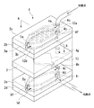
図1に、本発明の細胞培養装置の一例を示す。本実施態様の細胞培養装置1は、4つの細胞培養チャンバー2a,2b,2c,2dが積層され、細胞培養チャンバー2b,2c間に気体チャンバー3が設けられている。また、細胞培養装置1には、積層面に対して垂直方向に貫通して各チャンバーを接続する培養液灌流路4,5が設けられている。培養液は、培養液灌流路4を介して、細胞培養チャンバー2a,2b,2c,2d内部の培養液用流路構造12a,12b,12c,12dに供給され、培養液灌流路5を介して回収されるようになっている。つまり、細胞培養装置1内の培養液の流れが並列になるようになっている。気体チャンバー3内部の気体用流路構造13には、培養液は流されない。
【0009】
図2に、細胞培養装置1の位置A−Aにおける断面図を示す。
それぞれ一対の酸素透過性材料からなるシートによって構成されている細胞培養チャンバー2a,2b,2c,2dの内部には、複雑な三次元構造の空間(以下、培養液用流路構造という)12a,12b,12c,12dが設けられており、ここに細胞が固着され且つ培養液が灌流されるようになっている。複雑な三次元構造とすることにより、表面積が広くなっているので、より多くの細胞が固着できる。
気体チャンバー3(図3参照)は、内部に気体用流路構造13を有しており、気体用流路構造13内を気体(空気や酸素)が流れるようになっている。
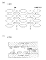
図4に、細胞培養チャンバーの培養液用流路構造内の培養液の流れ(a)及び気体チャンバー内での気体の流れ(b)を示す。
【0010】
細胞培養チャンバー2a,2b,2c,2d及び気体チャンバー3は、ともに、酸素透過性材料から構成されている。そのため、外気中及び気体チャンバー3内の酸素は、装置内を拡散して、培養液中に供給される。
培養液用流路構造内における培養液中の酸素濃度を一定に保持し、且つ、培養液用流路構造の表面に固着した細胞に、活性維持に必要とされる酸素を確実に供給するためには、チャンバー外表面と、チャンバー内部の気体用流路構造表面との間が0.2mm以下であり、チャンバー全体の厚さが1mm以下になるように設定することが好ましい。
ただし、外部から培養液を供給するチューブ接続のためと、装置全体の構造強度を保つために、最上部のシートについては1mm程度の厚みを持たせる必要がある。
【0011】
また、酸素供給量は、チャンバーと酸素との接触面積に比例する。従来であれば、細胞培養チャンバー2a以外の細胞培養チャンバー2b,2c,2dの場合、積層されていることで酸素との接触面積が減少するため、酸素供給量が減少し、細胞の活性が低下していた。しかしながら、本装置では、細胞培養チャンバー2b,2c間に気体用流路構造13を有する気体チャンバー3が設けられているので、気体用流路構造13内から酸素が供給され、細胞の活性を維持することができる。
したがって、複数、例えば2つの細胞培養チャンバーと、気体用チャンバーとを交互に順次積層していくことで、大容量の細胞培養装置を得ることもできる。
【0012】
このように、本発明の細胞培養装置は、肝細胞等の有用な細胞を、その活性を維持しつつ長時間、高密度培養することができ、大容量化も可能であるので、バイオリアクターとして好適に用いられる。
【0013】
前記酸素透過性材料としては、培養する細胞に対して適合性を有するものであれば、既知の任意の酸素透過性材料が使用可能であり、例えば、酸素透過性コンタクトレンズなどに用いられている生体適合性の酸素透過性材料などを挙げることができる。特に、透明性を有するものであれば、流路構造の表面の細胞の分布状況が観察できるので好適である。
そのような材料として、好ましくは、生体適合性のシリコーンゴム、特に好ましくはポリジメチルシロキサン(以下、PDMSという)が用いられる。PDMSは、安価で生体適合性を有する材料であり、また、透明性及びガス透過性を有している。
【0014】
図1に示した細胞培養装置1は、例えば以下のようにして製造することができる。
まず、一方の表面に、多数の突起や溝により立体的な流路構造が形成された凹部を有するPDMSシートを8枚作成する。次いで、各PDMSシートを、2枚ずつ、前記流路構造の凹部が内側になるように積層して、内部に培養液用流路構造を有する4個の細胞培養チャンバー2a,2b,2c,2dを得る。
上記と同様にして、内部に気体用流路構造を有する1個の気体チャンバー3を得る。
その後、細胞培養チャンバー2a,2b、気体チャンバー3、細胞培養チャンバー2c,2dを順次積層する。
また、各PDMSシートには、それぞれ同様の位置に、前記凹部に連絡する2つの貫通孔が設けられており、各チャンバーを積層した際に、この貫通孔が、培養液用流路構造に培養液を灌流させる培養液灌流路を構成する。
【0015】
前記PDMSシートは、例えば、図5に示すような従来公知のフォトリソグラフィー工程により作成することができる。
i)シリコンウェーハ51を用意し、
ii)該ウェーハ51上に、スピンコーティングによりSU−8(ネガ型フォトレジスト)膜52を形成する。次いで、
iii)所定のマスクパターン53(すなわち流路構造のパターン)を介して露光・現像を行い、ウェーハ上にパターンを転写し、マスター(原版)を得る。
iv)得られたパターンをマスクにして、CHF3プラズマ処理を行うことにより、表面がコーティングされて、ポリテトラフルオロエチレン等のフルオロカーボンポリマーの膜54が形成される。
v)その膜上に、未重合のPDMSを塗布してPDMS層55を形成し、重合させる。
vi)得られた透明なPDMS層を剥離し、酸素プラズマ処理を行う。得られたPDMSシート56の表面には、流路構造57が形成されている。
vii)得られたPDMSシートを、流路構造を内側になるようにして別のPDMSシート58と積層し、内部に流路構造を有するチャンバーを得る。このとき、別のPDMSシート58の表面には、流路構造が設けられていても設けられていなくてもよい。
【0016】
以下、図6に基づいて、本発明に係る細胞培養装置の別の実施形態を説明する。尚、以下に記載する実施形態において、図1に示した第1実施形態に対応する構成要素には、同一の符号を付してその詳細な説明を省略する。
図6に示す細胞培養装置1は、培養液の流れが、並列ではなく、直列である点で図1に示した細胞培養装置1と異なっている。
すなわち、図6に示した細胞培養装置1においては、培養液は、まず、培養液灌流路4eを介して培養液用流路構造12aの一端4aに供給され、流路構造12aの他端5a方向に流れ、他端5aから、培養液灌流路5eを介して培養液用流路構造12bの一端5bに供給される。一端5bに供給された培養液は、培養液用流路構造12b内を他端4b方向に流れ、他端4bから、他端4bと培養液用流路構造12cの一端4cとを連絡する培養液灌流路4f,4g,4hを介して培養液用流路構造12cの一端4cに供給される。一端4cに供給された培養液は、培養液用流路構造12c内を他端5c方向に流れ、他端5cから、他端5cと培養液用流路構造12dの一端5dとを連絡する培養液灌流路5fを介して培養液用流路構造12dの一端5dに供給される。一端5dに供給された培養液は、培養液用流路構造12d内を他端4d方向に流れ、他端4dから培養液灌流路4iを介して回収される。
このように、培養液の流れを直列にすることにより、並列の場合よりも流れがよくなる。
【0017】
次に、本発明の細胞培養チャンバーについて説明する。
本発明の細胞培養チャンバーは、酸素透過性材料からなり、内部に培養液の流れが一様となる流路構造を有し、該流路構造に細胞が固着されやすい構造を有し、且つ、該流路構造に培養液を灌流させるための培養液供給口及び培養液排出口を備える。
「培養液の流れが一様となる流路構造」とは、培養液供給口からの培養液を、その流路構造内全体に、概ね均質な量、概ね均質な速度、概ね均質な方向で流れるようにする構造であり、多様な高さや大きさの突起や穴、段差等によって形成される。
【0018】
図7は、本発明の好ましい実施形態における、細胞培養チャンバー内部の「培養液の流れが一様となる流路構造」70の一部を拡大した図である。この流路構造70の表面には、培養液供給口の部分から、比較的大きな突起71、それよりも小さい中程度の突起72、微細な矢印状の突起73、微細な細長い六角形状の突起74、微細な円形の穴75などが規則的に分散配置されている。これらの突起や穴は、同じ形状のもの同士は、培養液の流れる方向Dに対して垂直方向に平行且つ等間隔に配置されている。さらに、その突起や溝が設けられている面自体にも段差76が設けられている。これらによって、複雑で立体的な、網目状の流路構造が形成されている。
図8は、図7に示した流路構造の一部の平面図(a)及び方向Dにおける断面図(b)を概略的に示したものである。
【0019】
このような流路構造が内部に設けられていることによって、流路構造内に供給された培養液は、各突起や穴、段差により分散され、流路構造全体にわたって均質に広がるようになっており、培養液の一様な流れが得られる。
また、3次元的な流路構造であるため、細胞固着が促進される。これは、3次元的な構造であるため、突起と突起との間や穴の中で、流速が遅くなる部分が生じるためと考えられる。
【0020】
また、本発明の細胞培養チャンバーは、その製造方法が簡便であるため、設計上の自由度が大きく、様々なデザインの流路構造に対応可能である。
【0021】
酸素透過性材料としては、培養する細胞に対して適合性を有するものであれば、既知の任意の酸素透過性材料が使用可能であり、好ましくはPDMSが用いられる。PDMSは、上述したような利点を有するほか、図7に示したような複雑で微細な流路構造を容易に作成できるという利点を有する。
【0022】
本発明の細胞培養チャンバーは、前記培養液供給口及び培養液排出口を介して培養液を灌流させることにより、細胞培養装置として利用することができる。
また、本発明の細胞培養チャンバーは、上述した本発明の細胞培養装置を構成する細胞培養チャンバーとして好適に用いられる。
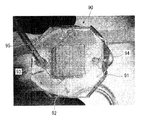
図9は、本発明の好ましい実施形態の細胞培養チャンバー91を備えた細胞培養装置90の一例である。この細胞培養装置90に用いられている細胞培養チャンバー91は、その内部に「培養液の流れが一様となる流路構造」92が設けられており、該流路構造の両端に、培養液供給口93及び培養液排出口94が設けられている。培養液供給口93には、培養液を供給するためのチューブ95が接続されている。培養液供給口93から供給された培養液は、流路構造を構成する多数の突起や穴により、流路構造92内全体に均一な量、均一な圧力で分散し、培養液排出口94方向へと流される。このように、培養液の流れが一様となって、培養液が流路構造92内全体に均質に分布するので、培養液中の栄養成分や酸素の供給や、培養液を介した老廃物の回収除去が偏りなく行われる。
【0023】
本発明の細胞培養装置及び細胞培養チャンバーを用いて培養可能な細胞は、その活性の維持に酸素を必要とする細胞であれば特に制限はなく、動物、特にヒト由来の肝細胞や繊維芽細胞など、応用上、非常に有用な細胞についても、長時間、その活性を維持しながら培養することができる。
遺伝子配列が同じであるヒト由来の細胞を高密度培養できれば、薬物スクリーニング等のヒト健康リスクを評価する上で説得力ある結果を得ることが可能になる。例えば、ヒト肝臓ガン由来細胞株Hep G2は、その機能の面で正常肝細胞に大きく劣るが、培養の簡便な株化細胞である。株化した肝由来細胞として、ヒトの正常肝細胞を用いることは事実上不可能であり、注目する機能さえ備えていれば、ガン化した細胞であってもヒト由来の細胞を用いる利点は大きい。
【0024】
また、細胞を固着させる前に予め、流路構造の表面をI型コラーゲン等でプレコーティングしておくと、細胞がより強固に流路構造に固着するので好ましい。培養時の培養液の灌流速度は、流路構造部に固着した細胞が剥がれない程度より遅ければ特に制限はなく、培養する細胞によって適宜設定すればよい。
【0025】
細胞培養時の培養液の流速は、5〜30μL/minとすることが好ましい。流速がこの範囲内にあると、流れによって生じる剪断応力によって細胞の固着や流路構造部への分布が妨げられず、また、死んだ細胞を除去することもできる。
また、灌流させている培養液は、培養液中に排出された老廃物や細胞の分泌物(例えばHep G2細胞培養時のアルブミン)を除去するために、少なくとも3〜4日毎に交換することが好ましい。
【0026】
上記細胞培養装置は、バイオリアクターとして好適に用いられる。特に、組織工学分野等において応用上有用な肝細胞や繊維芽細胞等の細胞について、高密度に、大容量で培養することができるので、臓器類の応答を再現可能なレベルの細胞数を達成でき、そのため、ハイブリッド型人工臓器や、動物実験の代替、薬剤スクリーニング等に利用することができる。
【0027】
【実施例】
本発明のおよびその効果を具体的に説明し、好ましい培養条件を求めるために、以下の試験例を行った。これらは本発明を限定するものではない。
以下の試験例では、以下の条件で培養した線維芽細胞株3T3−L1細胞及びヒト肝癌由来肝細胞株Hep G2細胞を用いた。
【0028】
<培養液>
Dulbecco's modified Minimum Essential Medium(DMEM、ニッスイ)に、1/10容量のウシ胎児血清、25mMのHEPES(hydroxyethylpiperazine-N'2-ethane sulfonic acid)、100U/mLペニシリン、100μg/mLストレプトマイシン、0.25μg/mLアンフォテリシンBをそれぞれ加えたもの。
<培養方法>
細胞の培養にはペトリディッシュを使用し、34〜35℃、20%O2及び5%CO2雰囲気下のインキュベータ内で培養を行った。
初期密度2.0×10⁴cells/cm2を目安として、2〜3日毎に培養液の交換を行った。また、Hep G2細胞については少なくとも2週間毎に、また、3T3−L1細胞については5〜6日毎に継代操作を行った。
【0029】
試験例1
1.<細胞の固着>
閉鎖系灌流回路上に、培養液タンク101、細胞を播種するためのバルブ102、ペリスタティックポンプ103、バブルトラップ104及び細胞培養装置105が配置された培養システム100(図10参照)を用いて以下の試験を行った。細胞培養装置105として、図7に示したのと同様の流路構造を有する細胞培養チャンバー(PDMS製;20×20mm、厚さ4mm;外表面と流路構造部との間の厚さ1.5mm)を用いた。
培養システム100を構成する部材はすべて、予め、オートクレーブにより滅菌した。細胞の播種前に、細胞培養チャンバーを、ダルベッコリン酸緩衝液(Dulbecco's phosphate buffered saline)で洗浄した。その後、34〜36℃、酸素濃度19.5%、二酸化炭素濃度5%のインキュベータ内で、0.03%I型コラーゲン水溶液(新田ゼラチン社製)を導入した後、1時間静置して細胞培養チャンバー内部の流路構造表面をコーティングした。
バルブ102を介して線維芽細胞株3T3−L1細胞を灌流回路内に添加(播種)し、濃度が9μg/mlとなるようにグルコースを添加後、インキュベーター内に一晩静置したところ、細胞培養チャンバーの流路構造の表面に細胞の固着がみとめられた。
固着しなかった細胞は培養液を灌流させることによってチャンバー内から取り除き、貯蔵タンク内で吸引除去して、以下の操作を行った。
【0030】
2.<灌流速度の影響>
灌流速度の影響を調べるために、培養液をいくつかの流速で灌流させて培養を行った。その際、グルコースについては、追加の添加をせずに濃度変化を計測した。
培養中、流路構造表面の細胞を観察したところ、細胞は、培養液の流れる方向に沿って分布していった。
また、活性を維持している細胞の数と、グルコース消費量とは関連しているので、培養開始後、灌流回路内のグルコース濃度の培養日数による変化を、グルコースアナライザー(Glucose analyser 2, Beckman Instruments Inc.)を用いて測定した。
【0031】
図11に、流速5μl/min(系列1:◆)及び10μl/min(系列2:■)の結果を示す。流速の遅い系列1の場合、培養5日目には、系列2に比べて比較的多くの細胞の死亡が確認された。この原因は、図11においてグルコース濃度が十分維持されていることからもわかるように、グルコースが不足したためではない。一方、流速の速い10μl/minの場合、グルコースの減少が順調であり、良好な培養条件が得られたことがわかる。この原因は、培養液の流速が速いため、グルコースが均質に配分されると同時に死細胞が適正に除去されたためであると考えられる。
【0032】
また、光学顕微鏡で観察したところ、比較的速い流速(例えば30μl/min)で培養液を灌流させた場合、細胞の形状は長く延びており、1週間以上生育することは困難であった。これは、流速が速すぎると、細胞が十分に固着せず、正常に分布することが困難になることを示している。また、この場合、培養開始後すぐに、多くの細胞の死亡が確認された。
なお、3T3−L1細胞の培養時に細胞にかかる剪断応力を測定したところ、培養に適した最大剪断応力は約12dyn/cm2以下であった。また、同様の操作をHep G2細胞を用いて行ったところ、培養に適した最大剪断応力は約4dyn/cm2以下であった。
【0033】
試験例2
培養液を上記試験例1の系列2と同じ流速で灌流させ、培養液中のグルコース濃度が低くなるとグルコースを添加した以外は上記試験例1の系列2と同様の条件で3T3−L1細胞(播種した細胞密度:1×10⁶cells/ml)及びHep G2細胞(播種した細胞密度:4×10⁶cells/ml)それぞれの培養を行った。播種した細胞密度が違うのは、培養初日のグルコース消費量がかなり異なっているためである。なお、5日目及び9日目に培養液の交換を行った。
細胞密度は培養6日目に最大に達した。その間に死亡した細胞は、流速を上げることによって取り除き、更に培養を続けたところ、13日目まで細胞密度の増加が続いた。
図12に、1日あたりのグルコース消費量の変化を示す(3T3−L1細胞(●)、Hep G2細胞(◆))。培養14日後まで、グルコースが順調に消費されており、細胞活性が維持されていたことがわかる。
図13に、Hep G2細胞培養時の灌流回路内のアルブミン濃度変化を示す。アルブミンの分泌量が多いほど細胞の活性が高いので、アルブミン濃度を測定することにより、細胞の活性の有無を確認することができる。図13に示す結果は、培養2週間後にも、細胞の活性が維持されていたことを示している。
【0034】
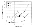
試験例3<気体用流路構造の効果>
気体用流路構造が設けられていることによる効果を示すために、(A)1つの細胞培養チャンバーからなる細胞培養装置、(B)図1に示す、気体用チャンバーが挿入された細胞培養装置、(C)4つの細胞培養チャンバーが積層された細胞培養装置を用いて、試験例2と同様の条件で、以下の実験を行った。
【0035】
図14に、3T3−L1細胞培養時のグルコース濃度の変化を示す((A):△、(B):■、(C):◆)。グルコース濃度の減少率は、(B)>(A)>(C)の順であった。この結果は、気体用チャンバーを設けた積層型の(B)が、単層で用いる場合よりも細胞の培養に適しており、一方、気体用チャンバーを設けない場合には、積層することにより、単層で用いる場合よりも細胞の活性が維持されにくくなることを示している。
【0036】
図15に、Hep G2細胞培養時のアルブミン分泌量((A):◆、(B):●、(C):■)の変化を示す。
気体チャンバーを有していない(C)の場合、アルブミン分泌量が1つの細胞培養チャンバーのみ(A)の場合よりも少ないのに対して、気体チャンバーを備えた(B)を用いた場合、細胞の活性は測定期間中(12日目まで)維持され、アルブミンの分泌量も最大であり、細胞の活性が高かった。
【0037】
【発明の効果】
本発明の細胞培養装置では、気体用流路構造が設けられており、該気体用流路構造内の酸素が、チャンバーの壁を透過して細胞培養チャンバー内に供給されるので、多数の細胞培養チャンバーを積層して、細胞培養装置を大容量化することができる。また、個々の細胞培養チャンバーの大きさを小さくすれば、大容量であり且つ小型の細胞培養装置となる。このような細胞培養装置を用いることにより、組織工学において生理学的な数の細胞を高密度で得ることができるので、バイオリアクター、特に、人工臓器等の作成において非常に有用である。これらは、各種臓器内での薬物動態やその影響を調べる上でも有用である。
また、本発明の細胞培養チャンバーは、培養液の流れが一様となる流路構造を有しているので、栄養成分や酸素の分布に偏りが生じにくく、老廃物の回収除去も良好である。そのため、細胞を、その活性を維持しつつ長時間、高密度培養することができる。
【図面の簡単な説明】
【図1】 本発明の細胞培養装置の一例を示す概略図である。
【図2】 図1の細胞培養装置の位置A−Aにおける縦断面図である。
【図3】 気体チャンバーの概略図である。
【図4】 流路構造内における培養液の流れ(a)及び気体チャンバー内部の気体の流れ(b)を示す概略図である。
【図5】 PDMSシートの製造工程の一例を示す図である。
【図6】 本発明の細胞培養装置の一例を示す概略図である。
【図7】 本発明の細胞培養チャンバーの一例において、その流路構造の一部を拡大した図である。
【図8】 図7に示した流路構造の一部の平面図(a)及び方向Dにおける断面図(b)を概略的に示した図である。
【図9】 本発明の細胞培養チャンバーを備えた細胞培養装置の一例を示す図である。
【図10】 本発明の細胞培養装置を用いた閉鎖系灌流システムの一例を示す概略図である。
【図11】 試験例1:培養液中のグルコース濃度を示すグラフである。
【図12】 試験例2:培養細胞の1日あたりのグルコース消費量(3T3−L1細胞(●)とHep G2細胞(◆))を示すグラフである。
【図13】 試験例2:Hep G2細胞の培養液中のアルブミン濃度の変化を示すグラフである。
【図14】 試験例3:3T3−L1細胞の培養液中のグルコース濃度の変化を示すグラフである。
【図15】 試験例3:Hep G2細胞によるアルブミン分泌量の変化を示すグラフである。
【符号の説明】
1…細胞培養装置、2a〜2d…細胞培養チャンバー、3…気体チャンバー、4,5…培養液灌流路、12a〜12d…培養液用流路構造、13…気体用流路構造、90…細胞培養装置、91…細胞培養チャンバー、92…流路構造、93…培養液供給口、94…培養液排出口[0001]
BACKGROUND OF THE INVENTION
The present invention relates to a cell culture device, a bioreactor, and a cell culture chamber. More specifically, for cells such as hepatocytes and fibroblasts that are useful in applications in the field of tissue engineering, etc., cells that can be cultured at high density while appropriately supplying nutrients and oxygen and removing waste products The present invention relates to a culture apparatus; a bioreactor using the same; and a cell culture chamber.
[0002]
[Prior art]
Currently, in the field of tissue engineering, bioreactors capable of continuously culturing cells while maintaining activity for a long time are being studied. These bioreactors are expected to be useful for the construction of hybrid-type artificial organs in the near future, and are expected to be used for transplantation, drug screening, and alternative experiments for animal experiments in the medical and pharmaceutical fields. Yes.
[0003]
In the culture of cells such as hepatocytes and fibroblasts, in order to maintain activities such as cell differentiation and proliferation, it is usually necessary to supply adherent carriers, nutrient components and oxygen. In addition, waste products generated by cell metabolism interfere with cell activity and need to be removed.
As one of the conventionally used cell culture methods, cells are attached to a flat surface of a culture vessel such as a Petri dish, and a nutrient solution or oxygen-containing culture solution is perfused there, thereby providing nutrient components. In addition, there is a method of simultaneously supplying oxygen and removing waste products. In this method, nutrient components and oxygen in the culture solution are diffused through the cell layer and supplied to individual cells, while waste products are transferred to the culture solution and removed.
[0004]
[Problems to be solved by the invention]
When creating a bioreactor, particularly an artificial organ, a large amount of cells must be cultured at high density.
However, as cell growth proceeds and the cell density increases, the thickness of the cell layer increases, making it difficult for nutrients and oxygen in the culture solution to reach all cells. In addition, waste products around the cells existing in the deep part are difficult to remove. Therefore, maintaining the activity of those cells becomes increasingly difficult.
In addition, oxygen supply to cells basically relies on natural dissolution of oxygen in the culture medium, so it is difficult to sufficiently dissolve the oxygen necessary for high-density cell culture in the culture medium. It is.
Furthermore, in the culture method described above, the position where the culture solution flows is likely to be biased due to the perfusion rate of the culture fluid, the tilt of the culture vessel, the thickness of the cell layer, and the like. Therefore, there is a problem that the distribution of nutrient components, oxygen, and waste products is uneven.
These problems are particularly conspicuous as the capacity of the culture container is increased, and it has been very difficult to perform culture with a larger capacity of the culture container.
[0005]
On the other hand, it is conceivable to configure a large-capacity cell culture apparatus by connecting a large number of small culture containers.
In this case, since a large amount of space is required if a large number of culture vessels are arranged in parallel, it is desirable to stack the culture vessels in order to save space.
However, when a large number of culture vessels are stacked, the contact area between oxygen and the culture vessel is reduced, so that the oxygen concentration in the culture solution becomes lower and the oxygen necessary for maintaining cell activity cannot be supplied. There is.
The present invention has been made in view of the circumstances as described above, and provides a cell culture apparatus capable of culturing cells at high density for a long time while maintaining their activity, and capable of increasing the capacity. The purpose is to do.
[0006]
[Means for Solving the Problems]
As a result of earnest research, the present inventors have made a cell in which at least two cell culture chambers made of an oxygen permeable material and having a culture fluid flow channel structure in which cells are fixed and the culture fluid is perfused are laminated. In the apparatus, it was discovered that the above object was achieved by providing a gas flow channel structure at least at one location between each cell culture chamber, and the present invention was completed.
[0007]
That is, the first invention of the present invention that solves the above-mentioned problems is made of an oxygen-permeable material, and has at least a culture fluid channel structure in which cells are fixed and the culture fluid is perfused.4Two cell culture chambers are stacked,
At least one location between each cell culture chamber consists of an oxygen permeable material.InsideGas channel structureA gas chamber having a,
eachCell cultureChamberAnd gas chamberIs a cell culture apparatus provided with a culture medium perfusion channel for connecting the culture medium in a direction perpendicular to the stacking surface and perfusing the culture medium in the culture fluid channel structure.
The cell culture chamber is made of an oxygen permeable material, has a flow channel structure therein, and includes a culture solution supply port and a culture solution discharge port for allowing the culture solution to perfuse into the flow channel structure. On the surface of the liquid crystal, the culture solution supplied from the culture solution supply port is dispersed, and projections, holes, or steps for distributing it uniformly are distributed, and the cells are fixed to the surface of the flow channel structure. It is preferable.
The oxygen permeable material is preferably polydimethylsiloxane.
The cell culture apparatus can also be used as a bioreactor..
[0008]
DETAILED DESCRIPTION OF THE INVENTION
Hereinafter, the present invention will be described in more detail with reference to the accompanying drawings.
FIG. 1 shows an example of the cell culture apparatus of the present invention. In the
[0009]
In FIG. 2, sectional drawing in position AA of the
Inside each of the
The gas chamber 3 (see FIG. 3) has a gas
FIG. 4 shows the flow (a) of the culture solution in the culture fluid flow channel structure of the cell culture chamber and the flow (b) of the gas in the gas chamber.
[0010]
The
To maintain a constant oxygen concentration in the culture fluid in the culture fluid flow channel structure and to reliably supply oxygen necessary for maintaining activity to the cells fixed on the surface of the culture fluid flow channel structure Is preferably set so that the distance between the outer surface of the chamber and the surface of the gas flow path structure inside the chamber is 0.2 mm or less and the thickness of the entire chamber is 1 mm or less.
However, the uppermost sheet needs to have a thickness of about 1 mm in order to connect the tube for supplying the culture solution from the outside and to maintain the structural strength of the entire apparatus.
[0011]
The oxygen supply amount is proportional to the contact area between the chamber and oxygen. Conventionally, in the case of the
Therefore, a large-capacity cell culture apparatus can be obtained by alternately and sequentially laminating a plurality of, for example, two cell culture chambers and gas chambers.
[0012]
As described above, the cell culture device of the present invention can cultivate useful cells such as hepatocytes at high density for a long time while maintaining the activity thereof, and can increase the capacity. Preferably used.
[0013]
As the oxygen permeable material, any known oxygen permeable material can be used as long as it is compatible with cells to be cultured. For example, it is used for an oxygen permeable contact lens. Examples include biocompatible oxygen-permeable materials. In particular, a material having transparency is suitable because the distribution state of cells on the surface of the channel structure can be observed.
As such a material, preferably a biocompatible silicone rubber, particularly preferably polydimethylsiloxane (hereinafter referred to as PDMS) is used. PDMS is an inexpensive and biocompatible material, and has transparency and gas permeability.
[0014]
The
First, eight PDMS sheets having a recess having a three-dimensional channel structure formed by a large number of protrusions and grooves are formed on one surface. Next, two PDMS sheets are stacked so that the recesses of the flow channel structure are inside, and four
In the same manner as described above, one
Thereafter, the
In addition, each PDMS sheet is provided with two through-holes communicating with the concave portion at the same position, and when the chambers are stacked, the through-holes are cultured in the culture fluid channel structure. A culture medium perfusion channel for perfusing the liquid is constructed.
[0015]
The PDMS sheet can be produced, for example, by a conventionally known photolithography process as shown in FIG.
i) preparing a
ii) An SU-8 (negative photoresist)
iii) Exposure / development is performed through a predetermined mask pattern 53 (that is, a flow path structure pattern), and the pattern is transferred onto the wafer to obtain a master (original).
iv) Using the obtained pattern as a mask, CHF3By performing the plasma treatment, the surface is coated, and a
v) On the film, unpolymerized PDMS is applied to form a
vi) The obtained transparent PDMS layer is peeled off and oxygen plasma treatment is performed. A
vii) The obtained PDMS sheet is laminated with another
[0016]
Hereinafter, another embodiment of the cell culture device according to the present invention will be described with reference to FIG. In the embodiment described below, the same reference numerals are given to the components corresponding to the first embodiment shown in FIG. 1, and the detailed description thereof will be omitted.
The
That is, in the
Thus, by making the flow of the culture solution in series, the flow becomes better than in the case of parallel.
[0017]
Next, the cell culture chamber of the present invention will be described.
The cell culture chamber of the present invention is made of an oxygen permeable material, has a flow channel structure in which the flow of the culture solution is uniform, has a structure in which cells are easily fixed to the flow channel structure, and The channel structure includes a culture solution supply port and a culture solution discharge port for perfusing the culture solution.
“A flow path structure in which the flow of the culture solution is uniform” means that the culture solution from the culture solution supply port is distributed in a generally uniform amount, a substantially uniform speed, and a generally uniform direction throughout the flow channel structure. The structure is made to flow, and is formed by protrusions, holes, steps, and the like having various heights and sizes.
[0018]
FIG. 7 is an enlarged view of a part of the “channel structure in which the flow of the culture solution is uniform” 70 inside the cell culture chamber in a preferred embodiment of the present invention. On the surface of the
FIG. 8 schematically shows a plan view (a) of a part of the flow channel structure shown in FIG.
[0019]
By providing such a flow path structure, the culture solution supplied in the flow path structure is dispersed by the protrusions, holes, and steps and spreads uniformly throughout the flow path structure. And a uniform flow of the culture solution is obtained.
Moreover, since it is a three-dimensional channel structure, cell adhesion is promoted. This is presumably because of the three-dimensional structure, there is a portion where the flow velocity becomes slow between the protrusions and in the hole.
[0020]
Moreover, since the cell culture chamber of the present invention is simple in its production method, it has a high degree of freedom in design, and can cope with flow channel structures of various designs.
[0021]
As the oxygen permeable material, any known oxygen permeable material can be used as long as it is compatible with cells to be cultured, and PDMS is preferably used. In addition to the advantages described above, PDMS has the advantage that a complicated and fine channel structure as shown in FIG. 7 can be easily created.
[0022]
The cell culture chamber of the present invention can be used as a cell culture device by perfusing a culture solution through the culture solution supply port and the culture solution discharge port.
The cell culture chamber of the present invention is suitably used as a cell culture chamber that constitutes the above-described cell culture apparatus of the present invention.
FIG. 9 is an example of a
[0023]
Cells that can be cultured using the cell culture apparatus and cell culture chamber of the present invention are not particularly limited as long as they require oxygen to maintain their activity, and are hepatocytes and fibroblasts derived from animals, particularly humans. For example, very useful cells for application can be cultured while maintaining their activity for a long time.
If human-derived cells having the same gene sequence can be cultured at high density, it is possible to obtain a convincing result in evaluating human health risks such as drug screening. For example, the human liver cancer-derived cell line Hep G2 is a cell line that is easy to culture, although its function is greatly inferior to that of normal hepatocytes. It is practically impossible to use human normal hepatocytes as established liver-derived cells, and as long as they have the function of interest, the advantage of using human-derived cells is great even for cancerous cells. .
[0024]
In addition, it is preferable to pre-coat the surface of the flow channel structure with type I collagen or the like before the cells are fixed, because the cells are more firmly fixed to the flow channel structure. The perfusion rate of the culture solution at the time of culture is not particularly limited as long as it is slower than the extent that the cells fixed to the flow channel structure are not peeled off, and may be appropriately set depending on the cells to be cultured.
[0025]
The flow rate of the culture solution during cell culture is preferably 5 to 30 μL / min. When the flow rate is within this range, the shearing stress generated by the flow does not prevent the cells from being fixed and distributed to the channel structure, and dead cells can be removed.
In addition, the perfusate culture medium can be replaced at least every 3 to 4 days in order to remove waste products and cell secretions (eg, albumin during Hep G2 cell culture) discharged into the culture medium. preferable.
[0026]
The cell culture device is suitably used as a bioreactor. In particular, cells such as hepatocytes and fibroblasts, which are useful for applications in the field of tissue engineering, can be cultured at high density and in large volumes, achieving a number of cells that can reproduce organ responses. Therefore, it can be used for hybrid artificial organs, substitution for animal experiments, drug screening, and the like.
[0027]
【Example】
In order to specifically explain the effects of the present invention and the preferred culture conditions,testAn example was done. These do not limit the invention.
belowtestIn the example, fibroblast cell line 3T3-L1 cells and human liver cancer-derived hepatocyte line Hep G2 cells cultured under the following conditions were used.
[0028]
<Culture solution>
Dulbecco's modified Minimum Essential Medium (DMEM, Nissui), 1/10 volume fetal bovine serum, 25 mM HEPES (hydroxyethylpiperazine-N′2-ethanesulfonic acid), 100 U / mL penicillin, 100 μg / mL streptomycin, 0.25 μg / Each with mL amphotericin B added.
<Culture method>
A Petri dish is used for culturing the cells, and the temperature is 34 to 35 ° C. and 20% O.2And 5% CO2Culture was performed in an incubator under an atmosphere.
Initial density 2.0 × 10⁴cells / cm2As a guide, the culture solution was changed every 2-3 days. In addition, the passage operation was performed at least every 2 weeks for Hep G2 cells and every 5 to 6 days for 3T3-L1 cells.
[0029]
1. <Cell adhesion>
Using a culture system 100 (see FIG. 10) in which a
All members constituting the
When fibroblast cell line 3T3-L1 cells were added (seeded) into the perfusion circuit through
The cells that did not adhere were removed from the chamber by perfusing the culture solution, removed by suction in a storage tank, and the following operation was performed.
[0030]
2. <Influence of perfusion rate>
In order to examine the influence of the perfusion rate, culture was performed by perfusing the culture solution at several flow rates. At that time, the change in concentration of glucose was measured without additional addition.
During the culture, the cells on the surface of the channel structure were observed, and the cells were distributed along the flowing direction of the culture solution.
In addition, since the number of cells that maintain activity and glucose consumption are related, the change in the glucose concentration in the perfusion circuit with the number of days of culture after the start of culturing was measured using a glucose analyzer (
[0031]
FIG. 11 shows the results at flow rates of 5 μl / min (series 1: ♦) and 10 μl / min (series 2: ■). In the case of
[0032]
When observed with an optical microscope, when the culture solution was perfused at a relatively high flow rate (for example, 30 μl / min), the shape of the cells was long and it was difficult to grow for more than one week. This indicates that if the flow rate is too high, the cells do not adhere sufficiently and it is difficult to distribute normally. Further, in this case, many cell deaths were confirmed immediately after the start of culture.
In addition, when the shear stress applied to the cells during the culture of 3T3-L1 cells was measured, the maximum shear stress suitable for the culture was about 12 dyn / cm.2It was the following. Moreover, when the same operation was performed using Hep G2 cells, the maximum shear stress suitable for culture was about 4 dyn / cm.2It was the following.
[0033]
Culture broth abovetest3T3-L1 cells (seeded cell density: 1) under the same conditions as in
The cell density reached a maximum on
FIG. 12 shows changes in glucose consumption per day (3T3-L1 cells (●), Hep G2 cells (♦)). It can be seen that until 14 days after culturing, glucose was consumed smoothly and the cell activity was maintained.
FIG. 13 shows changes in albumin concentration in the perfusion circuit during Hep G2 cell culture. The greater the amount of albumin secreted, the higher the activity of the cells. Therefore, by measuring the albumin concentration, the presence or absence of the activity of the cells can be confirmed. The results shown in FIG. 13 indicate that the cell activity was maintained even after 2 weeks of culture.
[0034]
In order to show the effect of the provision of the gas flow channel structure, (A) a cell culture device composed of one cell culture chamber, (B) a cell culture device in which the gas chamber is inserted as shown in FIG. (C) Using a cell culture apparatus in which four cell culture chambers are stacked,testThe following experiment was performed under the same conditions as in Example 2.
[0035]
FIG. 14 shows changes in glucose concentration during 3T3-L1 cell culture ((A): Δ, (B): ■, (C): ◆). The decreasing rate of the glucose concentration was in the order of (B)> (A)> (C). This result shows that the layered type (B) provided with the gas chamber is more suitable for cell culture than the case of using a single layer, whereas if the gas chamber is not provided, by laminating, It shows that the cell activity is less likely to be maintained than when used in a monolayer.
[0036]
FIG. 15 shows changes in albumin secretion ((A): ♦, (B): ●, (C): ■) during Hep G2 cell culture.
In the case of (C) which does not have a gas chamber, the amount of albumin secretion is smaller than that in the case of only one cell culture chamber (A), whereas when (B) having a gas chamber is used, Activity was maintained during the measurement period (until day 12), the amount of albumin secreted was also maximum, and the cell activity was high.
[0037]
【The invention's effect】
In the cell culture device of the present invention, a gas channel structure is provided, and oxygen in the gas channel structure is supplied to the cell culture chamber through the wall of the chamber. Cell culture apparatuses can be increased in capacity by stacking culture chambers. Further, if the size of each cell culture chamber is reduced, a large-capacity and small-sized cell culture apparatus can be obtained. By using such a cell culture device, a physiological number of cells can be obtained at high density in tissue engineering, and thus it is very useful in the production of bioreactors, particularly artificial organs. These are also useful for investigating pharmacokinetics in various organs and their effects.
In addition, since the cell culture chamber of the present invention has a flow path structure in which the flow of the culture solution is uniform, the distribution of nutrient components and oxygen is less likely to occur, and the collection and removal of waste products are also good. . Therefore, the cells can be cultured at a high density for a long time while maintaining the activity.
[Brief description of the drawings]
FIG. 1 is a schematic view showing an example of a cell culture apparatus of the present invention.
2 is a longitudinal sectional view at position AA of the cell culture device of FIG. 1. FIG.
FIG. 3 is a schematic view of a gas chamber.
FIG. 4 is a schematic view showing a flow (a) of a culture solution in a flow channel structure and a flow (b) of a gas inside a gas chamber.
FIG. 5 is a diagram showing an example of a PDMS sheet manufacturing process.
FIG. 6 is a schematic view showing an example of the cell culture apparatus of the present invention.
FIG. 7 is an enlarged view of a part of the flow channel structure in an example of the cell culture chamber of the present invention.
8 is a diagram schematically showing a plan view (a) of a part of the flow channel structure shown in FIG. 7 and a cross-sectional view (b) in a direction D. FIG.
FIG. 9 is a diagram showing an example of a cell culture apparatus provided with the cell culture chamber of the present invention.
FIG. 10 is a schematic view showing an example of a closed system perfusion system using the cell culture device of the present invention.
FIG. 11testExample 1: It is a graph which shows the glucose concentration in a culture solution.
FIG.testExample 2: It is a graph which shows glucose consumption (3T3-L1 cell (●) and Hep G2 cell (♦)) per day of cultured cells.
FIG. 13testExample 2: It is a graph which shows the change of the albumin density | concentration in the culture solution of Hep G2 cell.
FIG. 14testExample 3: It is a graph which shows the change of the glucose concentration in the culture solution of 3T3-L1 cell.
FIG. 15testExample 3: It is a graph which shows the change of the albumin secretion amount by Hep G2 cell.
[Explanation of symbols]
DESCRIPTION OF
Claims (4)
各細胞培養チャンバー間の少なくとも1カ所に、酸素透過性材料からなり、内部に気体用流路構造を有する気体チャンバーが挿入されており、
各細胞培養チャンバーおよび気体チャンバーを積層面に対して垂直方向に接続し、前記培養液用流路構造に培養液を灌流させるための培養液灌流路を備える細胞培養装置。At least four cell culture chambers made of an oxygen permeable material and having a culture fluid flow channel structure in which cells are fixed and the culture fluid is perfused are laminated,
At least one place between the cell culture chamber, Ri Do oxygen permeable material, a gas chamber having a gas flow path structure is inserted therein,
A cell culture apparatus comprising a culture solution perfusion channel for connecting each cell culture chamber and a gas chamber in a direction perpendicular to the laminated surface, and allowing the culture solution to perfuse the culture solution channel structure.
Priority Applications (1)
| Application Number | Priority Date | Filing Date | Title |
|---|---|---|---|
| JP2002316136A JP4389035B2 (en) | 2002-10-30 | 2002-10-30 | Cell culture device, bioreactor and cell culture chamber |
Applications Claiming Priority (1)
| Application Number | Priority Date | Filing Date | Title |
|---|---|---|---|
| JP2002316136A JP4389035B2 (en) | 2002-10-30 | 2002-10-30 | Cell culture device, bioreactor and cell culture chamber |
Publications (2)
| Publication Number | Publication Date |
|---|---|
| JP2004147555A JP2004147555A (en) | 2004-05-27 |
| JP4389035B2 true JP4389035B2 (en) | 2009-12-24 |
Family
ID=32459927
Family Applications (1)
| Application Number | Title | Priority Date | Filing Date |
|---|---|---|---|
| JP2002316136A Expired - Fee Related JP4389035B2 (en) | 2002-10-30 | 2002-10-30 | Cell culture device, bioreactor and cell culture chamber |
Country Status (1)
| Country | Link |
|---|---|
| JP (1) | JP4389035B2 (en) |
Families Citing this family (28)
| Publication number | Priority date | Publication date | Assignee | Title |
|---|---|---|---|---|
| JP4664646B2 (en) * | 2004-10-20 | 2011-04-06 | 一般社団法人オンチップ・セロミクス・コンソーシアム | Cell culture microchamber and cell structure construction method |
| JP4033265B2 (en) * | 2004-10-29 | 2008-01-16 | 財団法人北九州産業学術推進機構 | Cell tissue microdevice |
| JP2008519598A (en) * | 2004-11-11 | 2008-06-12 | エージェンシー フォー サイエンス,テクノロジー アンド リサーチ | Cell culture devices |
| US20090136982A1 (en) | 2005-01-18 | 2009-05-28 | Biocept, Inc. | Cell separation using microchannel having patterned posts |
| WO2006078470A2 (en) * | 2005-01-18 | 2006-07-27 | Biocept, Inc. | Cell separation using microchannel having patterned posts |
| US20060252087A1 (en) * | 2005-01-18 | 2006-11-09 | Biocept, Inc. | Recovery of rare cells using a microchannel apparatus with patterned posts |
| JP4586192B2 (en) * | 2005-03-08 | 2010-11-24 | 財団法人生産技術研究奨励会 | Cell culture chamber |
| JP4689383B2 (en) | 2005-07-19 | 2011-05-25 | 高木産業株式会社 | Culturing chamber, culturing apparatus, and method for feeding culture solution |
| US7745209B2 (en) | 2005-07-26 | 2010-06-29 | Corning Incorporated | Multilayered cell culture apparatus |
| JP4831730B2 (en) * | 2005-08-19 | 2011-12-07 | 株式会社東海ヒット | Medium storage device, petri dish lid |
| JP5731728B2 (en) * | 2007-05-02 | 2015-06-10 | 株式会社セルシード | Sealed cell culture vessel and cell culture method using the same |
| JP2008271915A (en) * | 2007-05-02 | 2008-11-13 | Cellseed Inc | System for supplying closed culture medium to culture small cells |
| KR100870982B1 (en) | 2007-05-03 | 2008-12-01 | 주식회사 바이오트론 | A multilayer Bio-reactor |
| CN101918532B (en) * | 2007-08-22 | 2016-03-30 | 普罗柏欧贞股份公司 | For culture systems and the method for vitro test immunogenicity and immunologic function |
| ES2639183T3 (en) | 2007-09-19 | 2017-10-25 | The Charles Stark Draper Laboratory, Inc. | Microfluidic structures with circular cross section |
| DE102008056037B4 (en) * | 2008-11-05 | 2012-10-31 | Fraunhofer-Gesellschaft zur Förderung der angewandten Forschung e.V. | Microfluidic bioreactor |
| WO2011000572A1 (en) | 2009-07-02 | 2011-01-06 | Patenthandel Portfoliofonds I Gmbh & Co. Kg | Method and device for detecting long-term biological effects in cells |
| US20110082563A1 (en) * | 2009-10-05 | 2011-04-07 | The Charles Stark Draper Laboratory, Inc. | Microscale multiple-fluid-stream bioreactor for cell culture |
| JP6164580B2 (en) | 2013-03-13 | 2017-07-19 | 国立大学法人 筑波大学 | Microchannel device and method related thereto |
| JP2013143955A (en) * | 2013-03-19 | 2013-07-25 | Cellseed Inc | Supply system for closed culture medium for culturing small cell |
| JP5837530B2 (en) * | 2013-04-22 | 2015-12-24 | 株式会社セルシード | Sealed cell culture vessel and cell culture method using the same |
| JP6366226B2 (en) * | 2013-05-24 | 2018-08-01 | 株式会社島津製作所 | Microchip reactor |
| EP3269798A4 (en) * | 2015-03-31 | 2018-10-31 | Dokkyo Medical University | Incubator provided with clean bench function, and incubator system |
| WO2017101096A1 (en) | 2015-12-18 | 2017-06-22 | 江阴瑞康健生物医学科技有限公司 | Combined bioreactor bin applicable to perfusion culture |
| JP2018023291A (en) * | 2016-08-08 | 2018-02-15 | 株式会社カネカ | Cell culture vessel, cell culture system using same, and cell culture method |
| IL292409A (en) * | 2019-10-24 | 2022-06-01 | Octane Biotech Inc | Cell culture chamber with improved cell-contacting surfaces |
| JP1681965S (en) | 2020-07-27 | 2021-03-29 | ||
| JP1699777S (en) | 2021-03-05 | 2021-11-15 |
-
2002
- 2002-10-30 JP JP2002316136A patent/JP4389035B2/en not_active Expired - Fee Related
Also Published As
| Publication number | Publication date |
|---|---|
| JP2004147555A (en) | 2004-05-27 |
Similar Documents
| Publication | Publication Date | Title |
|---|---|---|
| JP4389035B2 (en) | Cell culture device, bioreactor and cell culture chamber | |
| US5792653A (en) | Substrate for cell structures | |
| Gerlach et al. | Hepatocyte culture between three dimensionally arranged biomatrix-coated independent artificial capillary systems and sinusoidal endothelial cell co-culture compartments | |
| Ostrovidov et al. | Membrane-based PDMS microbioreactor for perfused 3D primary rat hepatocyte cultures | |
| Anada et al. | An oxygen-permeable spheroid culture system for the prevention of central hypoxia and necrosis of spheroids | |
| JP4586192B2 (en) | Cell culture chamber | |
| US10717961B2 (en) | Cell culture system and cell culture method | |
| EP2411501B1 (en) | Apparatus for cell or tissue culture | |
| EP3545074A1 (en) | Bi-layer multi-well cell culture platform | |
| JP2008519598A (en) | Cell culture devices | |
| Gerlach | Long-term liver cell cultures in bioreactors and possible application for liver support | |
| CN102203241B (en) | Cell storage method and cell transport method | |
| US20090286317A1 (en) | Modular culture system for maintenance, differentiation and proliferation of cells | |
| JPH06205665A (en) | Module for cultivating microorganism and for utilizing and/or maintaining metabolism | |
| JP2016093149A (en) | Cell culture apparatus, and cell culture method | |
| US20210123008A1 (en) | Cell culture chamber with improved cell-contacting surfaces | |
| RU2668157C1 (en) | Device for formation of a two-layer cellular model | |
| Nalayanda et al. | Engineering an artificial alveolar-capillary membrane: a novel continuously perfused model within microchannels | |
| CN114317272B (en) | Culture device for multicellular co-culture and cell culture method | |
| EP2130905A1 (en) | Method for culturing eukaryotic cells | |
| CN113846016B (en) | High-flux porous array chip, device, preparation method and application | |
| US20070207537A1 (en) | Bioreactor | |
| US7358082B2 (en) | Device and method for culturing cells | |
| ZA200109700B (en) | Modular cell carrier systems for the three-dimensional cell growth. | |
| JP2008271911A (en) | Method for culturing epithelial cell |
Legal Events
| Date | Code | Title | Description |
|---|---|---|---|
| A621 | Written request for application examination |
Free format text: JAPANESE INTERMEDIATE CODE: A621 Effective date: 20050728 |
|
| A131 | Notification of reasons for refusal |
Free format text: JAPANESE INTERMEDIATE CODE: A131 Effective date: 20080701 |
|
| A521 | Written amendment |
Free format text: JAPANESE INTERMEDIATE CODE: A523 Effective date: 20080826 |
|
| A131 | Notification of reasons for refusal |
Free format text: JAPANESE INTERMEDIATE CODE: A131 Effective date: 20090203 |
|
| A521 | Written amendment |
Free format text: JAPANESE INTERMEDIATE CODE: A523 Effective date: 20090406 |
|
| TRDD | Decision of grant or rejection written | ||
| A01 | Written decision to grant a patent or to grant a registration (utility model) |
Free format text: JAPANESE INTERMEDIATE CODE: A01 Effective date: 20090825 |
|
| A01 | Written decision to grant a patent or to grant a registration (utility model) |
Free format text: JAPANESE INTERMEDIATE CODE: A01 |
|
| A61 | First payment of annual fees (during grant procedure) |
Free format text: JAPANESE INTERMEDIATE CODE: A61 Effective date: 20090911 |
|
| FPAY | Renewal fee payment (event date is renewal date of database) |
Free format text: PAYMENT UNTIL: 20121016 Year of fee payment: 3 |
|
| R150 | Certificate of patent or registration of utility model |
Free format text: JAPANESE INTERMEDIATE CODE: R150 |
|
| FPAY | Renewal fee payment (event date is renewal date of database) |
Free format text: PAYMENT UNTIL: 20121016 Year of fee payment: 3 |
|
| S533 | Written request for registration of change of name |
Free format text: JAPANESE INTERMEDIATE CODE: R313533 |
|
| FPAY | Renewal fee payment (event date is renewal date of database) |
Free format text: PAYMENT UNTIL: 20121016 Year of fee payment: 3 |
|
| R350 | Written notification of registration of transfer |
Free format text: JAPANESE INTERMEDIATE CODE: R350 |
|
| FPAY | Renewal fee payment (event date is renewal date of database) |
Free format text: PAYMENT UNTIL: 20131016 Year of fee payment: 4 |
|
| R250 | Receipt of annual fees |
Free format text: JAPANESE INTERMEDIATE CODE: R250 |
|
| R250 | Receipt of annual fees |
Free format text: JAPANESE INTERMEDIATE CODE: R250 |
|
| R250 | Receipt of annual fees |
Free format text: JAPANESE INTERMEDIATE CODE: R250 |
|
| R250 | Receipt of annual fees |
Free format text: JAPANESE INTERMEDIATE CODE: R250 |
|
| LAPS | Cancellation because of no payment of annual fees |