JP4385759B2 - Lane departure prevention device - Google Patents
Lane departure prevention device Download PDFInfo
- Publication number
- JP4385759B2 JP4385759B2 JP2003421423A JP2003421423A JP4385759B2 JP 4385759 B2 JP4385759 B2 JP 4385759B2 JP 2003421423 A JP2003421423 A JP 2003421423A JP 2003421423 A JP2003421423 A JP 2003421423A JP 4385759 B2 JP4385759 B2 JP 4385759B2
- Authority
- JP
- Japan
- Prior art keywords
- departure
- steering
- lane
- driver
- intention
- Prior art date
- Legal status (The legal status is an assumption and is not a legal conclusion. Google has not performed a legal analysis and makes no representation as to the accuracy of the status listed.)
- Expired - Fee Related
Links
Images


Landscapes
- Steering Control In Accordance With Driving Conditions (AREA)
- Control Of Driving Devices And Active Controlling Of Vehicle (AREA)
- Regulating Braking Force (AREA)
Description
本発明は、走行中に自車両が走行車線から逸脱しそうになったときに、その逸脱を防止する車線逸脱防止装置に関するものである。 The present invention relates to a lane departure prevention apparatus for preventing a departure when a host vehicle is about to depart from a traveling lane during traveling.
従来の車線逸脱防止装置としては、自車両が走行車線から逸脱傾向にあるとき、操舵角から判断される運転者操作による操舵方向と自車両の逸脱方向とが一致しているか否かに基づいて、運転者の意思によりステアリング操作をしているか否かを判断し、運転者の操舵意思がないと判断された場合には、自車両の走行状態に基づいて算出された将来の車線からの逸脱推定量に応じて、左右の車輪に制動力差を与えることで車両にヨーモーメントを発生させて車線逸脱を回避するものが知られている(例えば、特許文献1参照)。
しかしながら、上記従来の車線逸脱防止装置にあっては、操舵角から判断される運転者操作による操舵方向と自車両の逸脱方向とに応じて運転者の操舵意思を判断しており、操舵意思があると判断された場合には逸脱回避制御を行わないようにしている。しかしながら、逸脱方向への操舵が検出されている場合であっても、横風や横方向に傾斜した路面等、自車両に外力が働くことにより、運転者の意思に反して走行中の車線から逸脱しそうになるという状況もあり、この場合も逸脱回避制御を適切に作動させたいという未解決の課題がある。
そこで、本発明は、上記従来例の未解決の課題に着目してなされたものであり、運転者の意図しない車線逸脱を適切に判断して逸脱回避制御を行うことができる車線逸脱防止装置を提供することを目的としている。
However, in the above conventional lane departure prevention device, the driver's steering intention is determined according to the steering direction by the driver's operation determined from the steering angle and the departure direction of the host vehicle. When it is determined that there is, the departure avoidance control is not performed. However, even when steering in a deviating direction is detected, the vehicle deviates from the driving lane against the driver's intention due to external forces acting on the host vehicle, such as crosswinds or laterally inclined road surfaces. There is a situation where this is likely to occur, and in this case as well, there is an unresolved problem of wanting to properly operate the departure avoidance control.
Therefore, the present invention has been made paying attention to the unsolved problems of the above-described conventional example, and is a lane departure prevention device capable of appropriately judging a lane departure unintended by the driver and performing departure avoidance control. It is intended to provide.
上記目的を達成するために、本発明に係る車線逸脱防止装置は、走行状態検出手段で自車両の走行状態を検出し、横加速度検出手段で自車両の横加速度を算出し、ステアリング状態検出手段でステアリングの状態を検出し、前記走行状態検出手段で検出された走行状態に基づいて、逸脱判断手段で自車両が走行車線から逸脱傾向にあることを判断し、前記逸脱判断手段により自車両が走行車線から逸脱傾向にあることが判断されたときに、前記ステアリング状態検出手段で検出されたステアリング状態と前記横加速度検出手段で検出された横加速度とに基づいて、逸脱意思判断手段で運転者の意思に反する逸脱であることを判断し、前記逸脱意思判断手段により運転者の意思に反する逸脱であることが判断されたときに、逸脱防止制御手段で、前記走行状態検出手段で検出された走行状態に応じて逸脱を回避する方向に自車両を制御する。また、前記ステアリング状態検出手段は、ステアリングホイールの舵角変化量を検出する。さらに、前記逸脱意思判断手段は、前記逸脱判断手段により自車両が走行車線から逸脱傾向にあることが判断されたときに、前記横加速度検出手段で検出した横加速度が所定値以上であり、且つ前記ステアリング状態検出手段で検出した舵角変化量が所定値より小さいとき、運転者の意思に反する逸脱であると判断する。 To achieve the above object, engagement Ru car line departure prevention apparatus of the present invention, in a running state detecting means detects a running state of the vehicle, and calculates a lateral acceleration of the vehicle in the lateral acceleration detecting means, the steering state The detecting means detects the steering state, and based on the traveling state detected by the traveling state detecting means, the departure determining means determines that the host vehicle tends to deviate from the traveling lane, and the departure determining means when the vehicle is determined to be in the deviation tendency from the driving lane, based on the detected lateral acceleration by the steering state detected steering state detecting means and the lateral acceleration detecting means, in deviation intention determining means When it is determined that the departure is contrary to the driver's intention, and the departure intention determination means determines that the departure is contrary to the driver's intention, the departure prevention control means Controlling the vehicle in a direction to avoid the deviation according to the traveling state detected by the running state detecting means. The steering state detecting means detects a steering angle change amount of the steering wheel. Further, the departure intention determination means has a lateral acceleration detected by the lateral acceleration detection means that is equal to or greater than a predetermined value when the departure determination means determines that the host vehicle tends to depart from the driving lane, and When the steering angle change detected by the steering state detecting means is smaller than a predetermined value, it is determined that the deviation is contrary to the driver's intention.
本発明によれば、自車両が走行車線から逸脱傾向にあるときには、ステアリング状態(舵角変化量)と横加速度とに基づいて、その逸脱が運転者の意図に反する逸脱であるか否かを判断し、運転者の意図に反する車線逸脱であるときにのみ、逸脱を回避する方向に自車両を制御するように各輪の制動力を制御する。したがって、舵角が変化していないにも関わらず横加速度が変化している場合には、横風等の外力が自車両に加わって車線逸脱しそうであると判断して逸脱回避制御を行うことができるなど、運転者の意図に反する車線逸脱を適切に防止することができる。 According to the present invention, when the host vehicle tends to deviate from the driving lane, whether or not the deviation is a deviation against the driver's intention is determined based on the steering state (steering angle change amount) and the lateral acceleration. Judgment is made and the braking force of each wheel is controlled so that the host vehicle is controlled in a direction to avoid the departure only when the lane departure is contrary to the driver's intention . Therefore, when the lateral acceleration changes even though the rudder angle does not change, it is determined that an external force such as a crosswind is applied to the host vehicle and the vehicle is likely to deviate from the lane, and departure avoidance control can be performed. It is possible to appropriately prevent lane departure that is contrary to the driver's intention .
以下、本発明の実施の形態を図面に基づいて説明する。
図1は、本発明における実施形態の概略構成図である。この車両は、自動変速機及びコンベンショナルディファレンシャルギヤを搭載した後輪駆動車両であり、制動装置は、前後輪とも左右輪の制動力(制動液圧)を独立に制御可能としている。
図中の符号1はブレーキペダル、2はブースタ、3はマスタシリンダ、4はリザーバ、9はエンジン、10は自動変速機であり、通常は、運転者によるブレーキペダル1の踏込み量に応じ、マスタシリンダ3で昇圧された制動流体圧が、前輪5FL、5FR及び後輪5RL、5RRの各ホイールシリンダ6FL〜6RRに供給されるようになっている。また、このマスタシリンダ3と各ホイールシリンダ6FL〜6RRとの間には制動流体圧制御回路7が介装されており、この制動流体圧制御回路7内で、各ホイールシリンダ6FL〜6RRの制動流体圧を個別に制御することも可能となっている。
Hereinafter, embodiments of the present invention will be described with reference to the drawings.
FIG. 1 is a schematic configuration diagram of an embodiment of the present invention. This vehicle is a rear wheel drive vehicle equipped with an automatic transmission and a conventional differential gear, and the braking device can control the braking force (braking fluid pressure) of the left and right wheels independently of the front and rear wheels.
In the figure,
前記制動流体圧制御回路7は、例えばアンチスキッド制御やトラクション制御に用いられる制動流体圧制御回路を利用したものであり、この実施形態では、各ホイールシリンダ6FL〜6RRの制動流体圧を、単独で増減圧することができるように構成されている。この制動流体圧制御回路7は、後述するコントロールユニット8からの制動流体圧指令値に応じて各ホイールシリンダ6FL〜6RRの制動流体圧を制御する。
The brake fluid
また、この車両には、自車両の走行車線逸脱防止判断用に走行車線内の自車両の位置を検出するための外界認識センサとして、CCDカメラ13及びカメラコントローラ14を備えている。このカメラコントローラ14では、CCDカメラ13で捉えた自車両前方の撮像画像から、道路区画線等のレーンマーカを検出して走行車線を検出し、さらに、その走行車線に対する自車両のヨー角Φ、走行車線中央からの横変位X、走行車線の曲率ρ、車線幅L等を算出することができるように構成されており、これらの算出信号はコントロールユニット8に出力される。
In addition, this vehicle includes a
また、この車両には、自車両に発生する横加速度Ygを検出する横加速度検出手段としての加速度センサ15、前記マスタシリンダ3の出力圧、所謂マスタシリンダ圧Pmを検出するマスタシリンダ圧センサ16、ステアリングホイール19の操舵角θを検出する操舵角センサ20、各車輪5FL〜5RRの回転速度即ち所謂車輪速度Vwj(j=FL〜RR)を検出する車輪速度センサ21FL〜21RR、方向指示器による方向指示操作を検出する方向指示スイッチ22、操舵トルクTstrを検出するトルクセンサ23が備えられ、それらの検出信号はコントロールユニット8に出力される。なお、操舵角センサ20及びトルクセンサ23がステアリング状態検出手段に対応している。
Further, the vehicle includes an
なお、検出された車両の走行状態データに左右の方向性がある場合には、何れも左方向を正方向とする。すなわち、ヨー角Φは左旋回時に正値となり、横変位Xは走行車線中央から左方にずれているときに正値となる。
次に、前記コントロールユニット8で行われる車線逸脱防止制御処理について、図2及び図3のフローチャートに従って説明する。この車線逸脱防止制御処理は、例えば10msec毎のタイマ割込処理によって実行される。
If the detected vehicle traveling state data has left and right directions, the left direction is the positive direction. That is, the yaw angle Φ becomes a positive value when turning left, and the lateral displacement X becomes a positive value when it is shifted to the left from the center of the traveling lane.
Next, the lane departure prevention control process performed by the control unit 8 will be described with reference to the flowcharts of FIGS. This lane departure prevention control process is executed by, for example, a timer interrupt process every 10 msec.
この車線逸脱防止制御処理では、まず図2のステップS1で、前記各センサやコントローラからの各種データを読み込む。具体的には、前記各センサで検出された横加速度Yg、各車輪速度Vwj、マスタシリンダ圧Pm、操舵角θ、方向指示スイッチ信号WS、操舵トルクTstr、カメラコントローラ14からの走行車線に対する車両ヨー角Φ、走行車線中央からの横変位X、走行車線の曲率ρ、走行レーン幅Lを読み込む。
In this lane departure prevention control process, first, in step S1 of FIG. 2, various data from the sensors and controllers are read. Specifically, the lateral acceleration Yg detected by the sensors, the wheel speeds Vw j , the master cylinder pressure Pm, the steering angle θ, the direction instruction switch signal WS, the steering torque T str , and the travel lane from the
次いでステップS2に移行して、前記ステップS1で読み込んだ各車輪速度VwFL〜VwRRのうち、非駆動輪である前左右輪速度VwFL、VwFRの平均値から自車両の車速Vを算出して、ステップS3に移行する。
V=(VwFL+VwFR)/2 ………(1)
なお、ABS制御等が作動している場合には、ABS制御内で推定された推定車体速度を用いるようにしてもよい。
Next, the routine proceeds to step S2 calculation, among the wheel speeds Vw FL ~Vw RR read in the step S1, before a non-driven wheel left and right wheel speeds Vw FL, from the average value of Vw FR of the vehicle the vehicle speed V Then, the process proceeds to step S3.
V = (Vw FL + Vw FR ) / 2 (1)
Note that, when the ABS control or the like is operating, the estimated vehicle speed estimated in the ABS control may be used.
ステップS3では、横変位X、横変位Xの変化量dX及び車線までの距離(L/2−X)に基づいて、下記(2)式をもとに自車両が逸脱するまでの逸脱予測時間Toutを算出し、ステップS4に移行する。
Tout=(L/2−X)/dX ………(2)
なお、この逸脱予測時間Toutは、自車両のヨー角Φ、走行車線の曲率ρ、車両のヨーレートφ、操舵角θ等により予測するようにしてもよい。
In step S3, based on the lateral displacement X, the variation dX of the lateral displacement X, and the distance to the lane (L / 2-X), the estimated departure time until the vehicle departs based on the following equation (2). T out is calculated, and the process proceeds to step S4.
T out = (L / 2−X) / dX (2)
The departure prediction time T out may be predicted based on the yaw angle Φ of the host vehicle, the curvature ρ of the traveling lane, the yaw rate φ of the vehicle, the steering angle θ, and the like.
ステップS4では、前記ステップS3で算出した逸脱予測時間Toutが逸脱判断閾値Tsより小さいか否かを判定し、Tout≧Tsであるときには、自車両は逸脱傾向にないと判断してステップS5に移行し、逸脱判断フラグFoutを逸脱傾向にないことを意味する“0”にリセットしてステップS6に移行する。
ステップS6では、下記(3)式をもとに目標ヨーモーメントMsを0(零)に設定してから後述するステップS16に移行する。
Ms=0 ………(3)
In step S4, the estimated time of departure T out was calculated in step S3 it is determined whether the deviation determination threshold Ts is smaller than that when a T out ≧ Ts is the vehicle is determined not to deviation tendency step S5 , The deviation determination flag Fout is reset to “0” which means that there is no tendency to deviate, and the process proceeds to step S6.
In step S6, the target yaw moment Ms is set to 0 (zero) based on the following equation (3), and then the process proceeds to step S16 described later.
Ms = 0 (3)
一方、前記ステップS4の判定結果が、Tout<Tsであるときには自車両は逸脱傾向にあると判断してステップS7に移行し、逸脱判断フラグFoutを逸脱傾向にあることを意味する“1”にセットしてステップS8に移行する。
ステップS8では、横変位Xの符号を判定し、X≧0であるときには自車両が走行車線中央から左方にずれていると判断してステップS9に移行し、逸脱方向Doutを左側であることを意味する“1”にセットして後述するステップS11に移行し、前記ステップS8の判定結果がX<0であるときには、ステップS10に移行して、逸脱方向Doutを右側であることを意味する“2”にセットしてステップS11に移行する。
On the other hand, when the determination result in step S4 is T out <Ts, it is determined that the host vehicle is in a tendency to deviate and the process proceeds to step S7, which means that the deviation determination flag F out is deviating from “1”. Set to "" and go to step S8.
In step S8, the sign of the lateral displacement X is determined. When X ≧ 0, it is determined that the host vehicle is shifted to the left from the center of the traveling lane, the process proceeds to step S9, and the departure direction Dout is on the left side. Is set to "1" which means that the process proceeds to step S11 to be described later. When the determination result in step S8 is X <0, the process proceeds to step S10 and the deviation direction Dout is set to the right side. The meaning is set to “2”, and the process proceeds to step S11.
ステップS11では、横加速度Ygが予め設定された閾値YgTH以上であるか否かを判定する。
ステップS11の判定結果が、Yg<YgTHであるときにはステップS12に移行して、運転者が車線変更をしようとしているか否かを判定する。この判定は、方向指示スイッチ信号WS及び操舵角θにより行い、方向指示スイッチ22がオン状態であるときに、方向指示スイッチ信号WSの符号により判断される方向と逸脱方向Doutとが一致している場合には、運転者の意図的な車線変更であると判断する。また、方向指示スイッチ22がオフ状態であるときに操舵角θが予め設定した操舵角設定値θS以上である場合にも、運転者の意図的な車線変更であると判断する。
In step S11, it is determined whether or not the lateral acceleration Yg is equal to or greater than a preset threshold Yg TH .
When the determination result in step S11 is Yg <Yg TH , the process proceeds to step S12 to determine whether or not the driver is changing the lane. This determination is performed based on the direction indicating switch signal WS and the steering angle θ. When the
そして、このステップS12で、運転者による車線変更の意図があると判断されたときには、前記ステップS5に移行し、車線変更の意図がないと判断されたときには、ステップS13に移行して、舵角の変化量Δθが予め設定した舵角変化量設定値ΔθS以上であるか否かを判定する。Δθ<ΔθSであるときには、運転者の意思による操舵ではないと判断して後述するステップS15に移行し、Δθ≧ΔθSであるときには、運転者の意思による操舵の可能性があると判断してステップS14に移行する。 When it is determined in step S12 that the driver intends to change lanes, the process proceeds to step S5. When it is determined that there is no intention to change lanes, the process proceeds to step S13, and the steering angle It is determined whether or not the amount of change Δθ is equal to or greater than a preset steering angle change amount setting value Δθ S. If Δθ <Δθ S, it is determined that the steering is not performed by the driver's intention, and the process proceeds to step S15 described later. If Δθ ≧ Δθ S, it is determined that there is a possibility of steering by the driver's intention. Then, the process proceeds to step S14.
ステップS14では、舵角変化量Δθが運転者の意図によって発生したのか、それとも例えば横風等の自車両に加わる外力によってステアリングが操舵されたのかを判断する。この判定は、舵角に変化が生じた際の操舵トルクTstrの符号によって行い、具体的には、図4のAに示すように、舵角に変化が生じた際の操舵トルクTstrが転舵方向に対して正の力(同方向)であるときには運転者の意図による操舵の変化、図4のBに示すように、転舵方向に対して負の力(逆方向)であるときには外力による操舵の変化であると判断する。 In step S14, it is determined whether the steering angle change amount Δθ is generated by the driver's intention or whether the steering is steered by an external force applied to the host vehicle such as a crosswind. This determination is made based on the sign of the steering torque T str when the steering angle changes. Specifically, as shown in FIG. 4A, the steering torque T str when the steering angle changes is obtained. When the force is positive (same direction) with respect to the turning direction, the steering changes due to the driver's intention. As shown in FIG. 4B, when the force is negative (reverse direction) with respect to the turning direction. It is determined that the steering is changed by an external force.
そして、舵角変化量Δθが運転者の意図によって発生したと判断されたときには、前記ステップS5に移行し、運転者の意図によるものではないと判断されたときには、ステップS15に移行する。
ステップS15では、横変位Xとその変化量dXとに基づいて、下記(4)式をもとに車両に発生させる目標ヨーモーメントMsを算出してからステップS16に移行する。
Ms=K1・X+K2・dX ………(4)
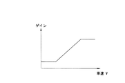
ここで、K1,K2は車速Vに応じて変動するゲインであり、夫々図5に示すゲイン算出マップを参照して算出する。
When it is determined that the steering angle change amount Δθ is generated by the driver's intention, the process proceeds to step S5. When it is determined that the steering angle change amount Δθ is not caused by the driver's intention, the process proceeds to step S15.
In step S15, based on the lateral displacement X and its change amount dX, the target yaw moment Ms to be generated in the vehicle is calculated based on the following equation (4), and then the process proceeds to step S16.
Ms = K 1 · X + K 2 · dX (4)
Here, K 1 and K 2 are gains that vary according to the vehicle speed V, and are calculated with reference to the gain calculation map shown in FIG.
なお、自車両の走行車線に対するヨー角Φ、横変位X及び前方走行車線曲率ρに基づいて、下記(5)式をもとに目標ヨーモーメントMsを算出するようにしてもよい。
Ms=Ka・Φ+Kb・X+Kc・ρ ………(5)
ここで、Ka,Kb,Kcは車速Vに応じて変動するゲインであり、Ka,Kbは図5に示すゲイン算出マップを参照し、Kcは図6に示すゲイン算出マップを参照して算出する。
ステップS16では、目標ヨーモーメントMs及びマスタシリンダ液圧Pmに応じて、各輪の目標制動液圧Psi(i=FL〜RR)算出する目標制動液圧算出処理を行う。
The target yaw moment Ms may be calculated based on the following equation (5) based on the yaw angle Φ, the lateral displacement X, and the forward travel lane curvature ρ with respect to the travel lane of the host vehicle.
Ms = K a · Φ + K b · X + K c · ρ (5)
Here, K a, K b, K c is a gain that varies according to vehicle speed V, K a, K b refers to the gain calculation map shown in FIG. 5, K c is the gain calculation map shown in FIG. 6 To calculate.
In step S16, a target brake hydraulic pressure calculation process for calculating the target brake hydraulic pressure Ps i (i = FL to RR) of each wheel according to the target yaw moment Ms and the master cylinder hydraulic pressure Pm is performed.
次いで、ステップS17に移行して、前記ステップS16で算出した目標制動液圧PsFL〜PsRRを制動流体制御回路7に出力してからタイマ割込処理を終了して所定のメインプログラムに復帰する。
前記ステップS16では、図3に示す目標制動液圧算出処理を行い、先ずステップS21で逸脱判断フラグFoutが逸脱傾向にないことを意味する“0”にリセットされているか否かを判定する。
Then, the processing proceeds to step S17, to return from the output of the target brake hydraulic pressures Ps FL ~Ps RR calculated at step S16 to the brake
In the step S16, it performs target brake hydraulic pressure calculation processing shown in FIG. 3, first departure determination flag F out in step S21 means that there is no the departure tendency "0" to determine whether it is reset.
ステップS21の判定結果が、Fout=0であるときにはステップS22に移行して、下記(6)式に示すように前左輪の目標制動液圧PsFL及び前右輪の目標制動液圧PsFRをマスタシリンダ液圧Pmから算出される前後配分を考慮した前輪マスタシリンダ圧Pmfの1/2に設定すると共に、下記(7)式に示すように後左輪の目標制動液圧PsRL及び後右輪の目標制動液圧PsRRをマスタシリンダ圧Pmから算出される前後配分を考慮した後輪マスタシリンダ圧Pmrの1/2に設定してから目標制動液圧算出処理を終了し、所定のメインプログラムに復帰する。
PsFL=PsFR=Pmf/2 ………(6)
PsRL=PsRR=Pmr/2 ………(7)
When the determination result in step S21 is F out = 0, the process proceeds to step S22, and the front left wheel target braking fluid pressure Ps FL and the front right wheel target braking fluid pressure Ps FR are obtained as shown in the following equation (6). Is set to ½ of the front wheel master cylinder pressure Pmf considering the front-rear distribution calculated from the master cylinder hydraulic pressure Pm, and the rear left wheel target braking hydraulic pressure Ps RL and the rear right wheel as shown in the following equation (7): The target brake hydraulic pressure Ps RR is set to ½ of the rear wheel master cylinder pressure Pmr in consideration of the front / rear distribution calculated from the master cylinder pressure Pm, and then the target brake hydraulic pressure calculation process is terminated, and a predetermined main Return to the program.
Ps FL = Ps FR = Pmf / 2 (6)
Ps RL = Ps RR = Pmr / 2 (7)
前記ステップS21の判定結果がFout=1であるときには、ステップS23に移行して、目標ヨーモーメントMsの絶対値|Ms|が設定値Ms1より小さいか否かを判定し、|Ms|<MS1であるときにはステップS24に移行して、下記(8)及び(9)式をもとに、後輪左右輪の制動力に差を発生させるような目標制動液圧差ΔPsFとΔPsRとを目標ヨーモーメントMsに基づいて算出してから後述するステップS26に移行する。
ΔPsF=0 ………(8)
ΔPsR=2×KBR×|Ms|/T ………(9)
When the determination result in step S21 is F out = 1, the process proceeds to step S23 to determine whether or not the absolute value | Ms | of the target yaw moment Ms is smaller than the set value Ms1, and | Ms | <MS1 When it is, the process proceeds to step S24, and based on the following equations (8) and (9), target braking hydraulic pressure differences ΔPs F and ΔPs R that cause a difference in braking force between the left and right rear wheels are set as targets. After calculating based on the yaw moment Ms, the process proceeds to step S26 described later.
ΔPs F = 0 (8)
ΔPs R = 2 × K BR × | Ms | / T (9)
一方、|Ms|≧MS1であるときにはステップS25に移行して、下記(10)及び(11)式をもとに、前後左右輪の制動力に差を発生させるような目標制動液圧差ΔPsFとΔPsRとを目標ヨーモーメントMsに基づいて算出してからステップS26に移行する。
ΔPsF=2×KBF×(|Ms|−Ms1)/T ………(10)
ΔPsR=2×KBR×Ms1/T ………(11)
ここで、Tは前後輪同一のトレッドである。また、KBRは制動力を制動液圧に換算する場合の換算係数であり、ブレーキ諸元により定まる。
On the other hand, when | Ms | ≧ MS1, the process proceeds to step S25, and based on the following equations (10) and (11), a target braking hydraulic pressure difference ΔPs F that causes a difference in the braking force between the front and rear left and right wheels. And ΔPs R are calculated based on the target yaw moment Ms, and then the process proceeds to step S26.
ΔPs F = 2 × K BF × (| Ms | −Ms1) / T (10)
ΔPs R = 2 × K BR × Ms1 / T (11)
Here, T is the same tread for the front and rear wheels. K BR is a conversion coefficient for converting braking force into braking hydraulic pressure, and is determined by brake specifications.
ステップS26では、目標ヨーモーメントMsを負即ち左方向に発生させようとしているか否かを判定し、Ms<0であるときにはステップS27に移行して、前左輪の目標制動圧PsFLを下記(12)式に示すようにマスタシリンダ圧Pmf/2に設定し、前右輪の目標制動圧PsFRを下記(13)式に示すようにマスタシリンダ圧Pmf/2に目標制動液圧差ΔPsFを加算した値に設定し、後左輪の目標制動圧PsRLを下記(14)式に示すようにマスタシリンダ圧Pmから算出される前後配分を考慮した後輪側マスタシリンダ圧Pmr/2に設定し、後右輪の目標制動圧PsRRを下記(15)式に示すように後輪マスタシリンダ圧Pmr/2に後輪側目標制動液圧差ΔPsRを加算した値に設定してから目標制動液圧算出処理を終了し、所定のメインプログラムに復帰する。
PsFL=Pmf/2 ………(12)
PsFR=Pmf/2+ΔPsF ………(13)
PsRL=Pmr/2 ………(14)
PsRR=Pmr/2+ΔPsR ………(15)
In step S26, determines whether or not trying to generate the target yaw moment Ms in the negative i.e. leftward, Ms <when it is 0, the process proceeds to step S27, before following the target braking pressure Ps FL of the left wheel (12 ) is set to the master cylinder pressure Pmf / 2 as shown in the expression before adding the target brake hydraulic pressure difference DerutaPs F to the master cylinder pressure Pmf / 2 as shown the target braking pressure Ps FR of the right wheel in the following equation (13) The rear left wheel target braking pressure Ps RL is set to the rear wheel side master cylinder pressure Pmr / 2 in consideration of the front-rear distribution calculated from the master cylinder pressure Pm as shown in the following equation (14): The target braking pressure Ps RR of the rear right wheel is set to a value obtained by adding the rear wheel side target braking hydraulic pressure difference ΔPs R to the rear wheel master cylinder pressure Pmr / 2 as shown in the following equation (15). Finish the calculation process To return to the predetermined main program.
Ps FL = Pmf / 2 (12)
Ps FR = Pmf / 2 + ΔPs F (13)
Ps RL = Pmr / 2 (14)
Ps RR = Pmr / 2 + ΔPs R (15)
一方、前記ステップS26の判定結果がMs≧0であるときにはステップS28に移行して、前左輪の目標制動圧PsFLを下記(16)式に示すようにマスタシリンダ圧Pmf/2に前輪側目標制動液圧差ΔPsFを加算した値に設定し、前右輪の目標制動圧PsFRを下記(17)式に示すようにマスタシリンダ圧Pmf/2に設定し、後左輪の目標制動圧PsRLを下記(18)式に示すように後輪側マスタシリンダ圧Pmr/2に後輪側目標制動液圧差ΔPsRを加算した値に設定し、後右輪の目標制動圧PsRRを下記(19)式に示すように後輪マスタシリンダ圧Pmr/2に設定してから目標制動液圧算出処理を終了し、所定のメインプログラムに復帰する。
PsFL=Pmf/2+ΔPsF ………(16)
PsFR=Pmf/2 ………(17)
PsRL=Pmr/2+ΔPsR ………(18)
PsRR=Pmr/2 ………(19)
On the other hand, front-wheel-side target master cylinder pressure Pmf / 2 as the process proceeds to step S28, indicating the target braking pressure Ps FL of the front left wheel in the following equation (16) when the judgment result of the step S26 is Ms ≧ 0 The brake hydraulic pressure difference ΔPs F is set to the added value, the front right wheel target brake pressure Ps FR is set to the master cylinder pressure Pmf / 2 as shown in the following equation (17), and the rear left wheel target brake pressure Ps RL Is set to a value obtained by adding the rear-wheel-side target braking hydraulic pressure difference ΔPs R to the rear-wheel-side master cylinder pressure Pmr / 2 as shown in the following equation (18), and the rear-right wheel target braking pressure Ps RR is set to the following (19 ) After setting the rear wheel master cylinder pressure Pmr / 2 as shown in the equation, the target brake fluid pressure calculation process is terminated, and the process returns to a predetermined main program.
Ps FL = Pmf / 2 + ΔPs F (16)
Ps FR = Pmf / 2 (17)
Ps RL = Pmr / 2 + ΔPs R (18)
Ps RR = Pmr / 2 (19)
図2の車線逸脱防止制御処理で、ステップS3〜S5及びS7〜S10の処理が逸脱判断手段に対応し、ステップS11〜S14の処理が逸脱意思判断手段に対応し、ステップS15〜S17の処理が逸脱防止制御手段に対応している。
したがって、今、運転者がステアリング操作を行っておらず、自車両に外力が働いていない状態で、自車両が走行車線に沿って直進走行しているものとする。この場合には、図2の逸脱防止制御処理において、ステップS3でTout<Tsとなる逸脱予測時間Toutが算出されるので、ステップS4からステップS5に移行して、逸脱判断フラグFout=0となって逸脱傾向にないことを示す状態となり、ステップS6で目標ヨーモーメントMsが“0”に設定される。これにより、図3のステップS22で各車輪5FL〜5RRの目標制動圧PsFL〜PsRRには、運転者の制動操作に応じたマスタシリンダ圧Pmf及びPmrが夫々設定され、運転者のステアリング操作に応じた走行状態が継続される。
In the lane departure prevention control process of FIG. 2, steps S3 to S5 and S7 to S10 correspond to departure determination means, steps S11 to S14 correspond to departure intention determination means, and steps S15 to S17 are performed. It corresponds to the deviation prevention control means.
Accordingly, it is assumed that the host vehicle is traveling straight along the travel lane in a state where the driver is not performing the steering operation and no external force is applied to the host vehicle. In this case, in the departure prevention control process of FIG. 2, a departure prediction time T out that satisfies T out <Ts is calculated in step S3, and therefore, the processing shifts from step S4 to step S5 and the departure determination flag F out = It becomes 0 and indicates that there is no tendency to deviate, and the target yaw moment Ms is set to “0” in step S6. Thus, the target braking pressure Ps FL ~Ps RR of each wheel 5FL~5RR in step S22 in FIG. 3, the master cylinder pressures Pmf and Pmr according to the brake operation of the driver are respectively set, the driver's steering operation The running state corresponding to is continued.
この状態から、運転者の脇見によって車両が走行車線の中央位置から徐々に左方向に逸脱を始めたとする。この場合には、ステップS3でTout≧Tsとなる逸脱予測時間Toutが算出されるので、ステップS4からステップS7に移行して、逸脱判断フラグFout=1となって逸脱傾向にあることを示す状態となる。自車両には外力が働いておらず、横加速度Ygは閾値YgTHより小さいので、ステップS11からステップS12を経てステップS13に移行する。運転者はステアリング操作を行っていないので、ステップS13の判定によりステップS15に移行して、前記(4)式をもとに目標ヨーモーメントMsが算出される。そして、この目標ヨーモーメントMsが自車両に発生するように、図3のステップS27で各車輪5FL〜5RRの目標制動圧PsFL〜PsRRが設定されることにより、逸脱回避方向である右方向への進路修正を的確に行う。 From this state, it is assumed that the vehicle gradually begins to deviate leftward from the center position of the travel lane due to the driver's sideways look. In this case, since the predicted departure time T out satisfying T out ≧ Ts is calculated in step S3, the process proceeds from step S4 to step S7, and the departure determination flag F out = 1 and there is a tendency of departure. It will be in the state which shows. Since no external force is acting on the host vehicle and the lateral acceleration Yg is smaller than the threshold Yg TH , the process proceeds from step S11 to step S13 through step S12. Since the driver does not perform the steering operation, the process proceeds to step S15 based on the determination in step S13, and the target yaw moment Ms is calculated based on the equation (4). Then, the target braking pressures Ps FL to Ps RR of the wheels 5FL to 5RR are set in step S27 of FIG. 3 so that the target yaw moment Ms is generated in the host vehicle, so that the right direction that is the departure avoidance direction is set. Correct the course to.
運転者が方向指示スイッチを操作して意図的に車線変更をしようとしているものとする。この場合には、ステップS12で方向指示スイッチ22の方向と逸脱方向フラグDoutによって判断される逸脱方向とが一致していると判断されてステップS5に移行し、逸脱判断フラグFout=0となって逸脱傾向にないことを示す状態となる。これにより、図3のステップS22で各車輪5FL〜5RRの目標制動圧PsFL〜PsRRには、運転者の制動操作に応じたマスタシリンダ圧Pm及びPmrが夫々設定され、運転者のステアリング操作に応じた走行状態が維持されるので、逸脱防止制御が作動することなく運転者の感覚に合った走行状態を継続することができる。
このように、運転者が方向指示スイッチを操作して意図的に車線変更をしようとして、走行車線から逸脱傾向にある場合には、逸脱防止制御を作動させないようにするので、運転者に違和感を与えることなく運転者の感覚に合った走行制御を行うことができる。
It is assumed that the driver is intentionally changing the lane by operating the direction switch. In this case, it is determined in step S12 that the direction of the
In this way, when the driver tries to intentionally change the lane by operating the direction indicating switch and tends to deviate from the traveling lane, the departure prevention control is not activated, so the driver feels uncomfortable. It is possible to perform traveling control that matches the driver's feeling without giving it.
運転者がステアリング操作を行っていない状態で、自車両に横風等の外力が働いて、運転者の意図に反して走行中の車線から左方向に逸脱傾向にあるものとする。この場合には、Yg≧YgTHとなるような横加速度Ygが発生し、ステップS11の判定によりステップS13に移行する。舵角が変化しておらず、操舵変化量Δθが閾値Δθsより小さくなっているので、ステップS13からステップS15に移行して、前記(4)式をもとに目標ヨーモーメントMsが算出される。これにより、この目標ヨーモーメントMsが自車両に発生するように、図3のステップS27で各車輪5FL〜5RRの目標制動圧PsFL〜PsRRが設定されることにより、逸脱回避方向である右方向への進路修正を的確に行う。
このように、操舵変化がない場合であっても、横加速度が所定値以上であるときには、運転者の意図に反する逸脱であると判断するので、自車両に横風等の外力が加わるなどにより走行中の車線から逸脱傾向にある場合には、確実に逸脱防止制御を作動して逸脱を回避することができる。
It is assumed that an external force such as a cross wind acts on the host vehicle when the driver is not performing a steering operation, and the vehicle tends to deviate leftward from the driving lane against the driver's intention. In this case, generated lateral acceleration Yg such that Yg ≧ Yg TH, the process proceeds to step S13 by the determination in step S11. Since the steering angle has not changed and the steering change amount Δθ is smaller than the threshold value Δθs, the routine proceeds from step S13 to step S15, and the target yaw moment Ms is calculated based on the above equation (4). . As a result, the target braking pressures Ps FL to Ps RR of the wheels 5FL to 5RR are set in step S27 in FIG. 3 so that the target yaw moment Ms is generated in the host vehicle. Correct the course in the direction.
As described above, even when there is no steering change, when the lateral acceleration is equal to or greater than a predetermined value, it is determined that the deviation is contrary to the driver's intention. When there is a tendency to deviate from the middle lane, the deviation prevention control can be reliably operated to avoid the deviation.
一方、自車両に横風等の外力が働いて、運転者の意図に反して左方向に逸脱傾向にあり、運転者によってステアリング操作されていないにも関わらず、舵角変化が生じている場合には、Δθ≧Δθsとなる操舵変化量Δθが検出されるので、ステップS13の判定によりステップS14に移行して、その操舵変化が運転者の操舵によって発生したのか、外力によって発生したのかを操舵トルクTstrの符号により判定する。運転者は操舵をしていないので、トルクセンサ23で検出された操舵トルクTstrが転舵方向に対して逆向きとなって、外力により操舵変化が発生したものと判断され、ステップS14からステップS15に移行して、前記(4)式をもとに目標ヨーモーメントMsが算出される。これにより、この目標ヨーモーメントMsが自車両に発生するように、図3のステップS27で各車輪5FL〜5RRの目標制動圧PsFL〜PsRRが設定されることにより、逸脱回避方向である右方向への進路修正を的確に行う。
On the other hand, when an external force such as a crosswind acts on the vehicle and the vehicle tends to deviate to the left against the driver's intention, and the steering angle is changing even though the driver is not steering. Since the steering change amount Δθ that satisfies Δθ ≧ Δθs is detected, the process proceeds to step S14 based on the determination in step S13, and the steering torque determines whether the steering change is caused by the driver's steering or the external force. Judged by the sign of T str . Since the driver is not steering, it is determined that the steering torque T str detected by the
なお、本実施形態においては、ステップS11で横加速度を検出しているが、この工程を除いても構わない。この場合、ステップS9の次にステップS12の判断が行われ、次にステップS13、S14によって自車両の舵角変化が外力によるものか否かを判断することになる。
したがって、舵角に変化が生じた際には、その舵角変化が運転者の操舵によって発生したのか、外力によって発生したのかをトルクセンサで検出された操舵トルクによって判断するので、運転者の意図しない舵角変化を確実に検出して、運転者の意図しない車線逸脱時に車両にヨーモーメントを発生させ、運転者に違和感のない逸脱回避制御を行うことができる。
In this embodiment, the lateral acceleration is detected in step S11, but this step may be omitted. In this case, the determination in step S12 is performed after step S9, and then in steps S13 and S14, it is determined whether or not the steering angle change of the host vehicle is due to an external force.
Therefore, when a change occurs in the steering angle, it is determined from the steering torque detected by the torque sensor whether the change in the steering angle is caused by the driver's steering or the external force. It is possible to reliably detect a change in the rudder angle and generate a yaw moment when the vehicle departs from a lane that is not intended by the driver, thereby performing departure avoidance control without causing the driver to feel uncomfortable.
以上のように、本実施形態においては、自車両の横加速度を検出し、自車両の走行状態に基づいて走行車線から逸脱傾向にあると判断されたときには、その逸脱が運転者の意思による逸脱であるのか、運転者の意思に反する逸脱であるのかを走行状態と横加速度とに基づいて判断するので、運転者の意図しない車線逸脱時には適切に逸脱回避制御を行うことができると共に、運転者の意図による車線逸脱時には逸脱回避制御を非作動として、運転者の違和感を抑制することができる。 As described above, in the present embodiment, when the lateral acceleration of the host vehicle is detected and it is determined that there is a tendency to deviate from the traveling lane based on the traveling state of the host vehicle, the departure is a deviation due to the driver's intention. Or a deviation against the driver's intention, based on the driving state and the lateral acceleration, it is possible to appropriately perform the departure avoidance control when the driver deviates from the lane and the driver does not intend. When the vehicle departs from the lane due to the intention, the departure avoidance control is deactivated, and the driver's uncomfortable feeling can be suppressed.
また、自車両が走行車線から逸脱傾向にあるときには、横加速度が所定値以上であり、且つ舵角変化量が所定値より小さいときに、運転者の意思に反する逸脱であると判断して逸脱回避制御を作動するので、舵角が変化していないにも関わらず、横加速度が発生して走行車線から逸脱しそうになった場合に、適切に車線逸脱を回避することができる。
さらに、自車両が走行車線から逸脱傾向にあるときには、舵角変化量が所定値以上であり、且つ操舵トルクが転舵方向に対して逆向きであるときに、運転者の意思に反する逸脱であると判断して逸脱回避制御を作動するので、操舵変化が自車両に働く外力等によって発生したことを確実に検出して、運転者の意図しない車線逸脱時に適切に車線逸脱を回避することができる。
Further, when the host vehicle tends to deviate from the driving lane, it is judged that the deviation is contrary to the driver's intention when the lateral acceleration is equal to or greater than a predetermined value and the steering angle change amount is smaller than the predetermined value. Since the avoidance control is activated, it is possible to appropriately avoid the lane departure when the lateral acceleration occurs and the vehicle is about to depart from the traveling lane even though the steering angle is not changed.
Furthermore, when the host vehicle tends to deviate from the driving lane, when the steering angle change amount is equal to or greater than a predetermined value and the steering torque is opposite to the steering direction, the deviation is contrary to the driver's intention. Since the departure avoidance control is activated based on the judgment that there is, it is possible to reliably detect that a steering change has occurred due to an external force or the like acting on the host vehicle, and to appropriately avoid the departure from the lane when the driver does not intend to leave the lane. it can.
また、操舵トルクが転舵方向に対して正値であるときには、運転者の意思による操舵変化であると判断して逸脱回避制御を非作動とするので、逸脱回避制御が作動してしまうことによる運転者の違和感を抑制することができる。
なお、上記実施形態においては、後輪駆動車に本発明を適用した場合について説明したが、前輪駆動車に本発明を適用することもできる。この場合には、ステップS2で、各車輪速度VwFL〜VwRRのうち、非駆動輪である後左右輪速度VwRL、VwRRの平均値から自車両の車速Vを算出すればよい。
Further, when the steering torque is a positive value with respect to the turning direction, it is determined that the steering change is caused by the driver's intention, and the departure avoidance control is deactivated. Therefore, the departure avoidance control is activated. A driver's discomfort can be suppressed.
In the above embodiment, the case where the present invention is applied to a rear wheel drive vehicle has been described. However, the present invention can also be applied to a front wheel drive vehicle. In this case, in step S2, among the wheel speeds Vw FL ~Vw RR, left and right wheel speeds Vw RL after a non-driven wheels, may be calculated vehicle speed V of the host vehicle from an average value of Vw RR.
6FL〜6RR ホイールシリンダ
7 制動流体圧制御回路
8 コントロールユニット
9 エンジン
13 CCDカメラ
14 カメラコントローラ
15 加速度センサ
16 マスタシリンダ圧センサ
20 操舵角センサ
21FL〜21RR 車輪速センサ
22 方向指示スイッチ
23 トルクセンサ
6FL to
Claims (2)
自車両の走行状態を検出する走行状態検出手段と、自車両の横加速度を検出する横加速度検出手段と、ステアリングの状態を検出するステアリング状態検出手段と、前記走行状態検出手段で検出された走行状態に基づいて、自車両が走行車線から逸脱傾向にあることを判断する逸脱判断手段と、該逸脱判断手段により自車両が走行車線から逸脱傾向にあることが判断されたときに、前記ステアリング状態検出手段で検出されたステアリング状態と前記横加速度検出手段で検出された横加速度とに基づいて、運転者の意思に反する逸脱であることを判断する逸脱意思判断手段と、該逸脱意思判断手段により運転者の意思に反する逸脱であることが判断されたときに、前記走行状態検出手段で検出された走行状態に応じて逸脱を回避する方向に自車両を制御する逸脱防止制御手段とを備え、前記ステアリング状態検出手段は、ステアリングホイールの舵角変化量を検出し、前記逸脱意思判断手段は、前記逸脱判断手段により自車両が走行車線から逸脱傾向にあることが判断されたときに、前記横加速度検出手段で検出した横加速度が所定値以上であり、且つ前記ステアリング状態検出手段で検出した舵角変化量が所定値より小さいとき、運転者の意思に反する逸脱であると判断することを特徴とする車線逸脱防止装置。 In a lane departure prevention apparatus for controlling the host vehicle so as to avoid a departure from the traveling lane of the host vehicle,
Travel state detection means for detecting the travel state of the host vehicle, lateral acceleration detection means for detecting the lateral acceleration of the host vehicle, steering state detection means for detecting the steering state, and travel detected by the travel state detection means Departure determination means for determining that the host vehicle tends to deviate from the traveling lane based on the state, and when the departure determining means determines that the host vehicle is in a tendency to depart from the driving lane, the steering state Based on the steering state detected by the detection means and the lateral acceleration detected by the lateral acceleration detection means, the departure intention determination means for determining that the departure is contrary to the driver's intention, and the departure intention determination means When it is determined that the deviation is contrary to the driver's intention, the deviation is automatically avoided in accordance with the running condition detected by the running condition detecting means. And a departure prevention control means for controlling both, the steering state detecting means detects a steering angle change amount of the steering wheel, the deviation intention determining means, departure tendency vehicle from the traffic lane by the deviation determining means When the lateral acceleration detected by the lateral acceleration detecting means is greater than or equal to a predetermined value and the steering angle change detected by the steering state detecting means is smaller than a predetermined value, the driver's A lane departure prevention apparatus, characterized in that it is determined that the departure is against the intention .
Priority Applications (1)
| Application Number | Priority Date | Filing Date | Title |
|---|---|---|---|
| JP2003421423A JP4385759B2 (en) | 2003-12-18 | 2003-12-18 | Lane departure prevention device |
Applications Claiming Priority (1)
| Application Number | Priority Date | Filing Date | Title |
|---|---|---|---|
| JP2003421423A JP4385759B2 (en) | 2003-12-18 | 2003-12-18 | Lane departure prevention device |
Publications (2)
| Publication Number | Publication Date |
|---|---|
| JP2005178534A JP2005178534A (en) | 2005-07-07 |
| JP4385759B2 true JP4385759B2 (en) | 2009-12-16 |
Family
ID=34782658
Family Applications (1)
| Application Number | Title | Priority Date | Filing Date |
|---|---|---|---|
| JP2003421423A Expired - Fee Related JP4385759B2 (en) | 2003-12-18 | 2003-12-18 | Lane departure prevention device |
Country Status (1)
| Country | Link |
|---|---|
| JP (1) | JP4385759B2 (en) |
Families Citing this family (4)
| Publication number | Priority date | Publication date | Assignee | Title |
|---|---|---|---|---|
| JP4770501B2 (en) * | 2006-02-08 | 2011-09-14 | 日産自動車株式会社 | Vehicle behavior control apparatus and vehicle behavior control method |
| JP5150955B2 (en) * | 2008-03-21 | 2013-02-27 | 本田技研工業株式会社 | Vehicle travel support device, vehicle, vehicle travel support program |
| KR101575277B1 (en) | 2014-08-11 | 2015-12-07 | 현대자동차 주식회사 | Apparatus and method of determining driving tendency of driver |
| JP6683065B2 (en) * | 2016-08-25 | 2020-04-15 | トヨタ自動車株式会社 | Lane departure suppression device |
-
2003
- 2003-12-18 JP JP2003421423A patent/JP4385759B2/en not_active Expired - Fee Related
Also Published As
| Publication number | Publication date |
|---|---|
| JP2005178534A (en) | 2005-07-07 |
Similar Documents
| Publication | Publication Date | Title |
|---|---|---|
| JP3982483B2 (en) | Lane departure prevention device | |
| JP4867313B2 (en) | Lane departure prevention device | |
| JP4534754B2 (en) | Lane departure prevention device | |
| JP4748122B2 (en) | Lane departure prevention device | |
| EP1298021B1 (en) | Lane-keep control system for vehicle | |
| JP3823924B2 (en) | Vehicle behavior control device | |
| JP4457891B2 (en) | Lane departure prevention device | |
| JP3642310B2 (en) | Lane departure prevention device | |
| US7200478B2 (en) | Lane departure prevention apparatus | |
| JP4835309B2 (en) | Lane departure prevention device | |
| JP2004322787A (en) | Lane departure prevention device | |
| EP2259955B1 (en) | Lane departure prevention system and method | |
| JP2004243783A (en) | Lane deviation preventing device | |
| JP4517854B2 (en) | Lane departure prevention apparatus and lane departure prevention method | |
| JP4385759B2 (en) | Lane departure prevention device | |
| JP2006306203A (en) | Lane deviation preventing device | |
| JP4396514B2 (en) | Lane departure prevention device | |
| JP2005182406A (en) | Lane departure prevention device | |
| JP4385751B2 (en) | Lane departure prevention device | |
| JP4601946B2 (en) | Lane departure prevention device | |
| JP4501967B2 (en) | Lane departure prevention device | |
| JP4423930B2 (en) | Lane departure prevention device | |
| JP4496758B2 (en) | Lane departure prevention device | |
| JP4613324B2 (en) | Lane departure prevention device | |
| JP4983089B2 (en) | Lane departure prevention device |
Legal Events
| Date | Code | Title | Description |
|---|---|---|---|
| A621 | Written request for application examination |
Free format text: JAPANESE INTERMEDIATE CODE: A621 Effective date: 20061113 |
|
| A131 | Notification of reasons for refusal |
Free format text: JAPANESE INTERMEDIATE CODE: A131 Effective date: 20081021 |
|
| A977 | Report on retrieval |
Free format text: JAPANESE INTERMEDIATE CODE: A971007 Effective date: 20081023 |
|
| A521 | Written amendment |
Free format text: JAPANESE INTERMEDIATE CODE: A523 Effective date: 20081127 |
|
| TRDD | Decision of grant or rejection written | ||
| A01 | Written decision to grant a patent or to grant a registration (utility model) |
Free format text: JAPANESE INTERMEDIATE CODE: A01 Effective date: 20090908 |
|
| A01 | Written decision to grant a patent or to grant a registration (utility model) |
Free format text: JAPANESE INTERMEDIATE CODE: A01 |
|
| A61 | First payment of annual fees (during grant procedure) |
Free format text: JAPANESE INTERMEDIATE CODE: A61 Effective date: 20090921 |
|
| R150 | Certificate of patent or registration of utility model |
Ref document number: 4385759 Country of ref document: JP Free format text: JAPANESE INTERMEDIATE CODE: R150 Free format text: JAPANESE INTERMEDIATE CODE: R150 |
|
| FPAY | Renewal fee payment (event date is renewal date of database) |
Free format text: PAYMENT UNTIL: 20121009 Year of fee payment: 3 |
|
| FPAY | Renewal fee payment (event date is renewal date of database) |
Free format text: PAYMENT UNTIL: 20121009 Year of fee payment: 3 |
|
| FPAY | Renewal fee payment (event date is renewal date of database) |
Free format text: PAYMENT UNTIL: 20131009 Year of fee payment: 4 |
|
| LAPS | Cancellation because of no payment of annual fees |