JP4382043B2 - Single fiber structure containing cellulose fiber and synthetic fiber and method for producing the same - Google Patents
Single fiber structure containing cellulose fiber and synthetic fiber and method for producing the same Download PDFInfo
- Publication number
- JP4382043B2 JP4382043B2 JP2005518378A JP2005518378A JP4382043B2 JP 4382043 B2 JP4382043 B2 JP 4382043B2 JP 2005518378 A JP2005518378 A JP 2005518378A JP 2005518378 A JP2005518378 A JP 2005518378A JP 4382043 B2 JP4382043 B2 JP 4382043B2
- Authority
- JP
- Japan
- Prior art keywords
- synthetic fibers
- fibers
- web
- fiber structure
- fiber
- Prior art date
- Legal status (The legal status is an assumption and is not a legal conclusion. Google has not performed a legal analysis and makes no representation as to the accuracy of the status listed.)
- Expired - Lifetime
Links
- 239000000835 fiber Substances 0.000 title claims description 131
- 229920002994 synthetic fiber Polymers 0.000 title claims description 87
- 239000012209 synthetic fiber Substances 0.000 title claims description 86
- 229920003043 Cellulose fiber Polymers 0.000 title claims description 28
- 238000004519 manufacturing process Methods 0.000 title description 4
- 239000000463 material Substances 0.000 claims description 15
- 229920001577 copolymer Polymers 0.000 claims description 6
- LYCAIKOWRPUZTN-UHFFFAOYSA-N ethylene glycol Natural products OCCO LYCAIKOWRPUZTN-UHFFFAOYSA-N 0.000 claims description 6
- 150000004676 glycans Chemical class 0.000 claims description 6
- 229920000098 polyolefin Polymers 0.000 claims description 6
- 229920001282 polysaccharide Polymers 0.000 claims description 6
- 239000005017 polysaccharide Substances 0.000 claims description 6
- 239000004952 Polyamide Substances 0.000 claims description 3
- QQVIHTHCMHWDBS-UHFFFAOYSA-N perisophthalic acid Natural products OC(=O)C1=CC=CC(C(O)=O)=C1 QQVIHTHCMHWDBS-UHFFFAOYSA-N 0.000 claims description 3
- 239000005014 poly(hydroxyalkanoate) Substances 0.000 claims description 3
- 229920000747 poly(lactic acid) Polymers 0.000 claims description 3
- 229920002647 polyamide Polymers 0.000 claims description 3
- 229920001707 polybutylene terephthalate Polymers 0.000 claims description 3
- 229920001610 polycaprolactone Polymers 0.000 claims description 3
- 229920000728 polyester Polymers 0.000 claims description 3
- 229920006149 polyester-amide block copolymer Polymers 0.000 claims description 3
- 229920000139 polyethylene terephthalate Polymers 0.000 claims description 3
- 239000005020 polyethylene terephthalate Substances 0.000 claims description 3
- 229920000903 polyhydroxyalkanoate Polymers 0.000 claims description 3
- KKEYFWRCBNTPAC-UHFFFAOYSA-L terephthalate(2-) Chemical compound [O-]C(=O)C1=CC=C(C([O-])=O)C=C1 KKEYFWRCBNTPAC-UHFFFAOYSA-L 0.000 claims description 3
- 239000004632 polycaprolactone Substances 0.000 claims description 2
- 239000012530 fluid Substances 0.000 description 31
- 238000000034 method Methods 0.000 description 27
- 230000003014 reinforcing effect Effects 0.000 description 17
- 239000000047 product Substances 0.000 description 16
- 238000001035 drying Methods 0.000 description 12
- 239000000123 paper Substances 0.000 description 11
- 238000000465 moulding Methods 0.000 description 10
- 230000008569 process Effects 0.000 description 10
- 239000007789 gas Substances 0.000 description 9
- 210000001519 tissue Anatomy 0.000 description 9
- 230000006835 compression Effects 0.000 description 8
- 238000007906 compression Methods 0.000 description 8
- 238000010438 heat treatment Methods 0.000 description 7
- 238000002844 melting Methods 0.000 description 7
- 230000008018 melting Effects 0.000 description 7
- 239000011347 resin Substances 0.000 description 6
- 229920005989 resin Polymers 0.000 description 6
- XLYOFNOQVPJJNP-UHFFFAOYSA-N water Substances O XLYOFNOQVPJJNP-UHFFFAOYSA-N 0.000 description 6
- 239000010410 layer Substances 0.000 description 5
- 239000001913 cellulose Substances 0.000 description 4
- -1 poly (hydroxy) Ether esters Chemical class 0.000 description 4
- 239000002002 slurry Substances 0.000 description 4
- 239000002759 woven fabric Substances 0.000 description 4
- 230000015572 biosynthetic process Effects 0.000 description 3
- 229920002678 cellulose Polymers 0.000 description 3
- 239000011248 coating agent Substances 0.000 description 3
- 238000000576 coating method Methods 0.000 description 3
- 238000010924 continuous production Methods 0.000 description 3
- 230000000694 effects Effects 0.000 description 3
- 229920005610 lignin Polymers 0.000 description 3
- 229920000642 polymer Polymers 0.000 description 3
- 238000004537 pulping Methods 0.000 description 3
- 238000004904 shortening Methods 0.000 description 3
- 239000000126 substance Substances 0.000 description 3
- 241000218631 Coniferophyta Species 0.000 description 2
- 238000010521 absorption reaction Methods 0.000 description 2
- 239000000654 additive Substances 0.000 description 2
- 238000005452 bending Methods 0.000 description 2
- 238000006243 chemical reaction Methods 0.000 description 2
- 238000007796 conventional method Methods 0.000 description 2
- 238000006073 displacement reaction Methods 0.000 description 2
- 238000009826 distribution Methods 0.000 description 2
- 238000004049 embossing Methods 0.000 description 2
- 239000004744 fabric Substances 0.000 description 2
- 230000001815 facial effect Effects 0.000 description 2
- 239000001257 hydrogen Substances 0.000 description 2
- 229910052739 hydrogen Inorganic materials 0.000 description 2
- 238000007373 indentation Methods 0.000 description 2
- 239000000976 ink Substances 0.000 description 2
- 230000007246 mechanism Effects 0.000 description 2
- 239000000203 mixture Substances 0.000 description 2
- 230000035699 permeability Effects 0.000 description 2
- 239000004033 plastic Substances 0.000 description 2
- 229920003023 plastic Polymers 0.000 description 2
- 229920001169 thermoplastic Polymers 0.000 description 2
- 239000002023 wood Substances 0.000 description 2
- 206010021639 Incontinence Diseases 0.000 description 1
- 241000256602 Isoptera Species 0.000 description 1
- 241000218922 Magnoliophyta Species 0.000 description 1
- 229920001410 Microfiber Polymers 0.000 description 1
- LSNNMFCWUKXFEE-UHFFFAOYSA-N Sulfurous acid Chemical compound OS(O)=O LSNNMFCWUKXFEE-UHFFFAOYSA-N 0.000 description 1
- 241001122767 Theaceae Species 0.000 description 1
- 230000002745 absorbent Effects 0.000 description 1
- 239000002250 absorbent Substances 0.000 description 1
- 239000006096 absorbing agent Substances 0.000 description 1
- 230000003213 activating effect Effects 0.000 description 1
- 230000002411 adverse Effects 0.000 description 1
- 230000009286 beneficial effect Effects 0.000 description 1
- 230000005540 biological transmission Effects 0.000 description 1
- 238000004061 bleaching Methods 0.000 description 1
- 238000007664 blowing Methods 0.000 description 1
- 230000008859 change Effects 0.000 description 1
- 238000004140 cleaning Methods 0.000 description 1
- 239000002131 composite material Substances 0.000 description 1
- 230000008878 coupling Effects 0.000 description 1
- 238000010168 coupling process Methods 0.000 description 1
- 238000005859 coupling reaction Methods 0.000 description 1
- 230000018044 dehydration Effects 0.000 description 1
- 238000006297 dehydration reaction Methods 0.000 description 1
- 238000000151 deposition Methods 0.000 description 1
- 239000007933 dermal patch Substances 0.000 description 1
- 239000000428 dust Substances 0.000 description 1
- 239000012467 final product Substances 0.000 description 1
- 239000011521 glass Substances 0.000 description 1
- 239000011121 hardwood Substances 0.000 description 1
- 230000036571 hydration Effects 0.000 description 1
- 238000006703 hydration reaction Methods 0.000 description 1
- 125000002887 hydroxy group Chemical group [H]O* 0.000 description 1
- 239000002917 insecticide Substances 0.000 description 1
- 238000009413 insulation Methods 0.000 description 1
- 239000012774 insulation material Substances 0.000 description 1
- 230000003993 interaction Effects 0.000 description 1
- 239000002655 kraft paper Substances 0.000 description 1
- 239000007788 liquid Substances 0.000 description 1
- 239000000155 melt Substances 0.000 description 1
- 239000002184 metal Substances 0.000 description 1
- 239000003658 microfiber Substances 0.000 description 1
- 239000002103 nanocoating Substances 0.000 description 1
- 239000004745 nonwoven fabric Substances 0.000 description 1
- 238000004806 packaging method and process Methods 0.000 description 1
- 238000007639 printing Methods 0.000 description 1
- 230000001681 protective effect Effects 0.000 description 1
- 239000005871 repellent Substances 0.000 description 1
- 230000002940 repellent Effects 0.000 description 1
- 230000003252 repetitive effect Effects 0.000 description 1
- 239000012260 resinous material Substances 0.000 description 1
- 239000003128 rodenticide Substances 0.000 description 1
- 238000007493 shaping process Methods 0.000 description 1
- 239000002356 single layer Substances 0.000 description 1
- 210000004872 soft tissue Anatomy 0.000 description 1
- 238000009987 spinning Methods 0.000 description 1
- 239000007921 spray Substances 0.000 description 1
- 239000003351 stiffener Substances 0.000 description 1
- 239000000725 suspension Substances 0.000 description 1
- 229920001059 synthetic polymer Polymers 0.000 description 1
- 239000004753 textile Substances 0.000 description 1
- 230000000930 thermomechanical effect Effects 0.000 description 1
- 239000004416 thermosoftening plastic Substances 0.000 description 1
- 238000009941 weaving Methods 0.000 description 1
Images


Classifications
-
- D—TEXTILES; PAPER
- D21—PAPER-MAKING; PRODUCTION OF CELLULOSE
- D21F—PAPER-MAKING MACHINES; METHODS OF PRODUCING PAPER THEREON
- D21F11/00—Processes for making continuous lengths of paper, or of cardboard, or of wet web for fibre board production, on paper-making machines
- D21F11/006—Making patterned paper
-
- Y—GENERAL TAGGING OF NEW TECHNOLOGICAL DEVELOPMENTS; GENERAL TAGGING OF CROSS-SECTIONAL TECHNOLOGIES SPANNING OVER SEVERAL SECTIONS OF THE IPC; TECHNICAL SUBJECTS COVERED BY FORMER USPC CROSS-REFERENCE ART COLLECTIONS [XRACs] AND DIGESTS
- Y10—TECHNICAL SUBJECTS COVERED BY FORMER USPC
- Y10T—TECHNICAL SUBJECTS COVERED BY FORMER US CLASSIFICATION
- Y10T428/00—Stock material or miscellaneous articles
- Y10T428/24—Structurally defined web or sheet [e.g., overall dimension, etc.]
- Y10T428/24479—Structurally defined web or sheet [e.g., overall dimension, etc.] including variation in thickness
-
- Y—GENERAL TAGGING OF NEW TECHNOLOGICAL DEVELOPMENTS; GENERAL TAGGING OF CROSS-SECTIONAL TECHNOLOGIES SPANNING OVER SEVERAL SECTIONS OF THE IPC; TECHNICAL SUBJECTS COVERED BY FORMER USPC CROSS-REFERENCE ART COLLECTIONS [XRACs] AND DIGESTS
- Y10—TECHNICAL SUBJECTS COVERED BY FORMER USPC
- Y10T—TECHNICAL SUBJECTS COVERED BY FORMER US CLASSIFICATION
- Y10T442/00—Fabric [woven, knitted, or nonwoven textile or cloth, etc.]
- Y10T442/60—Nonwoven fabric [i.e., nonwoven strand or fiber material]
Landscapes
- Nonwoven Fabrics (AREA)
- Paper (AREA)
Description
本発明は、セルロース繊維と合成繊維とを組み合わせて含む繊維構造体に関し、より特定的には、異なるマイクロ領域を有する繊維構造体に関する。 The present invention relates to a fiber structure including a combination of cellulose fibers and synthetic fibers, and more particularly to a fiber structure having different micro regions.
紙ウェブなどのセルロース繊維構造体は、当該技術分野において周知である。今日、低密度繊維ウェブは、紙タオル、トイレ用ティッシュ、フェイシャルティッシュ、ナプキン、ウェット拭き取り布などのために一般的に使用されている。かかる紙製品の大量の消費により、それら製品の改良型変形及びそれらの製造方法に対する要求が生じてきた。かかる要求に応じるべく、抄紙業者は、機械及び資源の費用と、製品を消費者へ引き渡す総費用との均衡を図らなければならない。 Cellulose fiber structures such as paper webs are well known in the art. Today, low density fiber webs are commonly used for paper towels, toilet tissue, facial tissues, napkins, wet wipes, and the like. The large consumption of such paper products has created a need for improved variants of the products and methods for their production. In order to meet these demands, papermakers must balance the cost of machinery and resources with the total cost of delivering products to consumers.
セルロース繊維を含む様々な天然繊維並びに多様な合成繊維が抄紙の際に用いられてきた。典型的なティッシュペーパーは、主としてセルロース繊維からなる。ティッシュに使用されるセルロース繊維の圧倒的大部分は、木から得られる。長繊維を含有する針葉樹(球果植物又は裸子植物)及び短繊維を含有する広葉樹(落葉樹又は被子植物)などの多くの種類が使用される。更に、多くの異なるパルプ化手法が用いられることもある。一方には、クラフト(Kraft)及び亜硫酸パルプ化法及びそれに続く強い漂白があり、これは可撓性のリグニンを含まない非常に白い繊維を製造する。もう一方では、サーモメカニカル又はケミメカニカルパルプ化法があり、これは、あまり可撓性でなく、日光で黄変し易く、湿潤性が乏しいリグニン高含有繊維を製造する。一般的な規則として、繊維のリグニン含有量が高いほど、安価である。 Various natural fibers including cellulosic fibers as well as various synthetic fibers have been used in papermaking. A typical tissue paper consists mainly of cellulose fibers. The overwhelming majority of cellulose fibers used in tissues are derived from wood. Many types are used, such as conifers (cone or gymnosperm) containing long fibers and hardwoods (deciduous or angiosperms) containing short fibers. In addition, many different pulping techniques may be used. One is Kraft and sulfite pulping followed by intense bleaching, which produces very white fibers that do not contain flexible lignin. On the other hand, there is a thermomechanical or chemimechanical pulping process, which produces lignin-rich fibers that are not very flexible, tend to yellow with sunlight, and have poor wettability. As a general rule, the higher the lignin content of the fiber, the cheaper it is.
抄紙には広範な繊維が使用されるにもかかわらず、木から得られるセルロース繊維は、使い捨てティッシュ及びタオル製品において独占的に使用される時には制限的である。木部繊維は、一般に、乾燥弾性率が高く、直径が相対的に大きく、そのため、それらの曲げ剛性が高くなる。かかる高剛性繊維は、剛直で柔軟でないティッシュを生成する傾向がある。更に、木部繊維は、乾燥すると剛性が高くなり(典型的には、結果として生じる製品の柔軟性を乏しくさせる)、水和により濡れると剛性が低くなる(典型的には、結果として生じる製品の吸収性を乏しくさせる)という望ましくない特性を有する。また、木部系繊維は、それら繊維の形状又はモルホロジーをあまり「工作する」ことができないので制限的である。相対的に僅かな種類の変形を除いて、製紙業者は、自然が供するものを受け入れなければならない。 Despite the wide range of fibers used in papermaking, cellulosic fibers from wood are limited when used exclusively in disposable tissue and towel products. The xylem fibers generally have a high dry elastic modulus and a relatively large diameter, and therefore their bending rigidity is high. Such high stiffness fibers tend to produce rigid and non-soft tissue. Furthermore, xylem fibers become more rigid when dried (typically making the resulting product less flexible) and less rigid when wetted by hydration (typically the resulting product). Undesirably). Also, xylem fibers are limited because they are less able to “craft” the shape or morphology of the fibers. With the exception of relatively few types of deformations, papermakers must accept what nature offers.
使用できるウェブを形成するために、典型的な使い捨てティッシュ及びタオル製品における繊維は、化学的な相互作用を介して互いに結合される。湿潤強度が必要とされない場合、結合は、一般的には、セルロース分子上のヒドロキシル基間で天然に生じる水素結合に制限される。最終製品において、一時的又は永久的な湿潤強度が必要とされる場合、強化樹脂を添加することができる。これらの樹脂は、セルロースと共有結合反応するか、又は既存の水素結合の周りに保護的な分子被膜を形成するかのいずれかによって作用する。いずれにせよ、これら結合機構の全ては制限的である。それらは、剛直で弾力のない結合を生じる傾向があり、製品の柔軟性及びエネルギー吸収特性に悪影響を及ぼす。 In order to form a usable web, the fibers in typical disposable tissue and towel products are bonded together through chemical interactions. If wet strength is not required, bonding is generally limited to naturally occurring hydrogen bonds between hydroxyl groups on the cellulose molecule. If the final product requires temporary or permanent wet strength, a reinforced resin can be added. These resins either act by covalently reacting with cellulose or by forming a protective molecular coating around existing hydrogen bonds. In any case, all of these coupling mechanisms are restrictive. They tend to produce a rigid and non-resilient bond, adversely affecting the product's flexibility and energy absorption properties.
互いに及び/又はセルロース繊維に熱融着する能力を有する合成繊維の使用は、前述の制限を克服する優れた方法である。木部系セルロース繊維は、熱可塑性ではなく、故に他の繊維に熱結合することができない。合成熱可塑性ポリマーは、紡糸されて非常に小さな繊維直径となることができ、一般にはセルロースよりも弾性率が低い。この結果、繊維の曲げ剛性は非常に低くなり、これは、良好な製品の柔軟性を助長する。更に、合成繊維の機能的断面を、紡糸プロセス中に微小工作(micro-engineered)することができる。合成繊維はまた、水安定性の弾性率という望ましい特性を有する。セルロース繊維と違って、適切に設計された合成繊維は濡れても適切な弾性率を失わず、故に、かかる繊維で作成されたウェブは吸収作業中も崩壊しない。ティッシュ製品において熱結合された合成繊維を使用することにより、(柔軟性及び湿潤強度に関しては良好である)水抵抗性の高強度結合により接合された(柔軟性に関しては良好である)高可撓性繊維の強固な網状構造が生じる。 The use of synthetic fibers that have the ability to be heat fused to each other and / or to cellulose fibers is an excellent way to overcome the aforementioned limitations. The xylem cellulose fiber is not thermoplastic and therefore cannot be thermally bonded to other fibers. Synthetic thermoplastic polymers can be spun into very small fiber diameters and are generally less elastic than cellulose. As a result, the bending stiffness of the fiber is very low, which facilitates good product flexibility. Furthermore, the functional cross section of the synthetic fiber can be micro-engineered during the spinning process. Synthetic fibers also have the desirable property of elastic modulus for water stability. Unlike cellulose fibers, well-designed synthetic fibers do not lose the proper modulus when wet, and therefore webs made with such fibers do not collapse during the absorbent operation. High flexibility (good in terms of flexibility) joined by a water-resistant high strength bond (good in terms of flexibility and wet strength) by using heat bonded synthetic fibers in tissue products A strong network structure of the conductive fibers is generated.
従って、本発明は、セルロース繊維と合成繊維とを組み合わせて含む繊維構造体と、かかる繊維構造体を作成するための方法に関する。 Accordingly, the present invention relates to a fiber structure comprising a combination of cellulose fibers and synthetic fibers and a method for making such a fiber structure.
本発明は、新規の単一繊維構造体及びかかる繊維構造体を作成するための方法を提供する。本発明の単一又は単プライ繊維構造体は、繊維構造体の全体にわたってランダムに分配された複数のセルロース繊維と、繊維構造体の全体にわたって非ランダム反復パターンで分配された複数の合成繊維とを含む。非ランダム反復パターンは、実質的に連続的な網状パターン、実質的に半連続的なパターン、隔離されたパターン及びこれらの任意の組み合わせを含み得る。繊維構造体は、相対的に密度が高い複数のマイクロ領域と、相対的に密度が低い複数のマイクロ領域とを含み得る。これら複数のマイクロ領域の少なくとも1つ、最も典型的には相対的に密度が高い複数のマイクロ領域は、複数の合成繊維の非ランダム反復パターンと位置合せされる。 The present invention provides a novel single fiber structure and a method for making such a fiber structure. The single or single-ply fiber structure of the present invention comprises a plurality of cellulose fibers randomly distributed throughout the fiber structure and a plurality of synthetic fibers distributed in a non-random repeating pattern throughout the fiber structure. Including. Non-random repeating patterns may include a substantially continuous mesh pattern, a substantially semi-continuous pattern, an isolated pattern, and any combination thereof. The fiber structure may include a plurality of micro regions having a relatively high density and a plurality of micro regions having a relatively low density. At least one of the plurality of microregions, most typically the plurality of relatively dense microregions, is aligned with a non-random repeating pattern of the plurality of synthetic fibers.
繊維構造体の1つの実施形態において、複数の合成繊維の少なくとも一部は、合成繊維及び/又はセルロース繊維と共接合される。繊維は、有利には、非ランダム反復パターンを含む区域において共接合され得る。 In one embodiment of the fibrous structure, at least some of the plurality of synthetic fibers are co-joined with synthetic fibers and / or cellulose fibers. The fibers can advantageously be co-joined in areas containing non-random repeating patterns.
合成繊維は、ポリオレフィン類、ポリエステル類、ポリアミド類、ポリヒドロキシアルカノエート類、多糖類及びこれらの任意の組み合わせからなる群から選択される材料を含み得る。合成繊維は、ポリ(エチレンテレフタレート)、ポリ(ブチレンテレフタレート)、ポリ(1,4−シクロヘキシレンジメチレンテレフタレート)、イソフタル酸コポリマー類、エチレングリコールコポリマー類、ポリオレフィン類、ポリ(乳酸)、ポリ(ヒドロキシエーテルエステル)、ポリ(ヒドロキシエーテルアミド)、ポリカプロラクトン、ポリエステルアミド、多糖類及びこれらの任意の組み合わせからなる群から選択される材料を更に含み得る。 Synthetic fibers can include materials selected from the group consisting of polyolefins, polyesters, polyamides, polyhydroxyalkanoates, polysaccharides, and any combination thereof. Synthetic fibers include poly (ethylene terephthalate), poly (butylene terephthalate), poly (1,4-cyclohexylenedimethylene terephthalate), isophthalic acid copolymers, ethylene glycol copolymers, polyolefins, poly (lactic acid), poly (hydroxy) Ether esters), poly (hydroxy ether amides), polycaprolactones, polyester amides, polysaccharides, and materials selected from the group consisting of any combination thereof.
本発明による単一繊維構造体を作成するための方法は、(a)繊維ウェブの全体にわたってランダムに分配された複数のセルロース繊維と、繊維ウェブの全体にわたってランダムに分配された複数の合成繊維とを含む繊維ウェブを準備する工程と、(b)ウェブにおける合成繊維の少なくとも一部の再分配を引き起こし、複数の合成繊維の実質的な一部が非ランダム反復パターンで繊維構造体の全体にわたって分配される単一繊維構造体を形成する工程とを本質的に含む。 The method for making a single fiber structure according to the present invention comprises: (a) a plurality of cellulose fibers randomly distributed throughout the fibrous web; and a plurality of synthetic fibers randomly distributed throughout the fibrous web; Providing a fiber web comprising: (b) causing redistribution of at least a portion of the synthetic fibers in the web, wherein a substantial portion of the plurality of synthetic fibers is distributed throughout the fiber structure in a non-random repeating pattern. Forming a single fiber structure.
ウェブの全体にわたってランダムに分配された複数のセルロース繊維と、ウェブ(本明細書中では「初期」ウェブとも呼ばれる)の全体にわたってランダムに分配された複数の合成繊維とを含む繊維ウェブは、複数の合成繊維と混合された複数のセルロース繊維を含む水性スラリーを提供し、この水性スラリーをフォーミング部材上に堆積させ、そのスラリーを部分的に脱水することによって調製され得る。この方法はまた、初期繊維ウェブをフォーミング部材から成形部材へ移送し、この成形部材上で、初期ウェブを更に脱水させ、所望のパターンに従って成形され得る工程を包含し得る。繊維ウェブにおける合成繊維の再分配工程は、ウェブが成形部材上に配置される間に行うことができる。更に、又はあるいは、再分配工程はウェブが乾燥ドラムの表面などの乾燥表面と結合している時に行うことができる。 A fibrous web comprising a plurality of cellulosic fibers randomly distributed throughout the web and a plurality of synthetic fibers randomly distributed throughout the web (also referred to herein as an “initial” web) It can be prepared by providing an aqueous slurry comprising a plurality of cellulose fibers mixed with synthetic fibers, depositing the aqueous slurry on a forming member and partially dewatering the slurry. The method can also include the steps of transferring the initial fibrous web from the forming member to the forming member, whereupon the initial web can be further dewatered and formed according to the desired pattern. The process of redistributing synthetic fibers in the fibrous web can be performed while the web is placed on the molded member. Additionally or alternatively, the redistribution step can be performed when the web is bonded to a drying surface, such as the surface of a drying drum.
更に具体的には、繊維構造体を作成するための方法は、複数の流体透過性区域と、複数の流体不透過性区域とを含む成形部材を準備する工程と、初期繊維ウェブを成形部材上に対面関係で配置する工程と、ウェブを乾燥表面に移送する工程と、ウェブにおける合成繊維の再分配を引き起こすため十分な温度まで初期ウェブを加熱する工程とを含む。合成繊維の再分配は、合成繊維の溶融、合成繊維の少なくとも部分的な移動、又はこれらの組み合わせにより達成され得る。 More specifically, a method for making a fibrous structure includes providing a molded member that includes a plurality of fluid permeable areas and a plurality of fluid impermeable areas; and an initial fiber web on the molded member. Placing the web in a face-to-face relationship, transferring the web to a dry surface, and heating the initial web to a temperature sufficient to cause redistribution of the synthetic fibers in the web. Synthetic fiber redistribution can be accomplished by melting synthetic fibers, at least partial movement of synthetic fibers, or a combination thereof.
成形部材は、微視的に単一平面状であり、ウェブに接触する側と、このウェブに接触する側に対向する裏側とを有する。最も典型的には開口を含む流体透過性区域は、成形部材のウェブ側から裏側まで延在する。繊維ウェブが成形部材上に配置される時、ウェブの繊維は成形部材のマイクロ形状に適合する傾向があり、故に、成形部材上に配置された繊維ウェブは、成形部材の複数の流体透過性区域に相当する第一の複数のマイクロ領域と、成形部材の複数の流体不透過性区域に相当する第二の複数のマイクロ領域とを含む。流体圧力差が成形部材上に配置されたウェブに付与され、成形部材の流体透過性区域への、第一の複数のウェブのマイクロ領域の偏向が促進され得る。 The molding member is microscopically flat and has a side that contacts the web and a back side that faces the side that contacts the web. Most typically, the fluid permeable area, including the openings, extends from the web side to the back side of the molded member. When the fibrous web is disposed on the molded member, the fibers of the web tend to conform to the micro shape of the molded member, and therefore the fibrous web disposed on the molded member has a plurality of fluid permeable areas of the molded member. And a second plurality of micro regions corresponding to a plurality of fluid-impermeable areas of the molded member. A fluid pressure differential may be applied to the web disposed on the forming member to facilitate deflection of the micro-regions of the first plurality of webs to the fluid permeable area of the forming member.
成形部材上に配置されたウェブは、成形部材を通して、又は反対側から熱ガスで加熱され得る。成形部材を通してウェブが加熱される時、主に、第一の複数のマイクロ領域が熱ガスに曝露される。ウェブは、乾燥ドラムと結合している間も加熱され得る。ウェブは、繊維ウェブにおける合成繊維の再分配を引き起こすために十分な温度まで加熱され、それにより、合成繊維は非ランダム反復パターンを含み、その一方で、セルロース繊維は、ウェブの全体にわたってランダムに分配されたまま残る。 The web placed on the molded member can be heated with hot gas through the molded member or from the opposite side. When the web is heated through the forming member, primarily the first plurality of micro-regions are exposed to the hot gas. The web can also be heated while combined with the drying drum. The web is heated to a temperature sufficient to cause redistribution of the synthetic fibers in the fiber web so that the synthetic fibers contain a non-random repeating pattern, while the cellulose fibers are randomly distributed throughout the web. It remains to be done.
成形部材の1つの実施形態は、対面関係でパターン付き枠組みに接合された補強要素を具備する。かかる実施形態において、パターン付き枠組みは、成形部材のウェブ側を含む。パターン付き枠組みは、樹脂、金属、ガラス、プラスチック又はその他好適な材料からなる群から選択される好適な材料を含むことができる。パターン付き枠組みは、実質的に連続的なパターン、実質的に半連続的なパターン、隔離されたパターン又はこれらの任意の組み合わせを有し得る。 One embodiment of the molded member comprises a reinforcing element joined to the patterned framework in a face-to-face relationship. In such embodiments, the patterned framework includes the web side of the molded member. The patterned frame can include a suitable material selected from the group consisting of resin, metal, glass, plastic or other suitable material. The patterned framework may have a substantially continuous pattern, a substantially semi-continuous pattern, an isolated pattern, or any combination thereof.
本発明の方法は、有利には、成形部材と、乾燥ドラムの表面などの好適な圧縮用表面との間で初期ウェブを型押しして、初期ウェブの選択された一部を高密度化する工程を含み得る。最も典型的には、ウェブの高密度化された一部は、成形部材の複数の流体不透過性区域に相当する一部である。 The method of the present invention advantageously embosses an initial web between a molded member and a suitable compression surface, such as the surface of a drying drum, to densify a selected portion of the initial web. Steps may be included. Most typically, the densified portion of the web is the portion corresponding to the plurality of fluid impermeable areas of the molded member.
本明細書中の図面に例証された工業的な連続プロセスにおいて、フォーミング部材及び成形部材のそれぞれは、支持ローラの周りを連続的に移動するエンドレスベルトを含む。 In the industrial continuous process illustrated in the drawings herein, each of the forming and forming members includes an endless belt that moves continuously around a support roller.
本明細書で使用する時、次の用語は、次に示す意味を有する。 As used herein, the following terms have the following meanings.
「単一繊維構造体」は、複数のセルロース繊維及び合成繊維を含む構成であり、これらの繊維は中で絡み合って、幾つかの所定の微視的な形状特性、物理的特性、及び外観特性を有する単プライシート製品を形成する。セルロース及び/又は合成繊維は、単一繊維構造体の内部で、当該技術分野において既知であるように積層されてもよい。 A “single fiber structure” is a configuration that includes a plurality of cellulose fibers and synthetic fibers that are intertwined in a number of predetermined microscopic shape characteristics, physical characteristics, and appearance characteristics. A single-ply sheet product is formed. Cellulose and / or synthetic fibers may be laminated within a single fiber structure as is known in the art.
「マイクロ形状」又はその変形は、繊維構造体の全体的な(即ち「巨視的な」)形状と違って、その全体構成に関連しない構造体の相対的に小さな(即ち、「微視的な」)細部(details)、例えば表面テクスチャなどを指す。例えば、本発明の成形部材においては、流体透過性区域及び流体不透過性区域の組み合わせが、成形部材のマイクロ形状を構成する。「巨視的な」又は「巨視的に」を含む用語は、X−Y表面などの二次元構成に置かれる時を考慮した場合、構造体又はその一部の「マクロ形状」又は全体的な形状について言う。例えば、巨視的なレベルでは、繊維構造体は、それが平坦な表面上に配置される時、相対的に薄くて平坦なシートを含む。しかしながら、微視的なレベルでは、繊維構造体は、異なる高さを形成する複数のマイクロ領域、例えば、第一の高さを有する網状領域と、枠組み領域の全体にわたって分散され、且つその枠組み領域から外側に向かって延在し、第二の高さを形成する複数の繊維「ピロー」とを含み得る。 A “micro-shape” or a deformation thereof, unlike the overall (ie, “macroscopic”) shape of a fiber structure, is a relatively small (ie, “microscopic” of a structure that is not related to its overall configuration. ") Refers to details, such as surface texture. For example, in the molded member of the present invention, the combination of the fluid permeable area and the fluid impermeable area constitutes the micro shape of the molded member. The term including “macroscopic” or “macroscopic” refers to the “macro shape” or the overall shape of a structure or part thereof, when considered when placed in a two-dimensional configuration such as an XY surface Say about. For example, at a macroscopic level, a fibrous structure includes a relatively thin and flat sheet when it is placed on a flat surface. However, at a microscopic level, the fiber structure is distributed over a plurality of micro-regions that form different heights, for example, a mesh region having a first height and a framework region, and the framework region. And a plurality of fibers “pillows” extending outward from and forming a second height.
「坪量」は、繊維構造体の(典型的には平方メートル単位で測定される)単位面積の(グラム単位で測定される)重量であり、この単位面積は、繊維構造体の平面に取られる。坪量が測定される単位面積の大きさ及び形状は、異なる坪量を有する領域の相対的及び絶対的な大きさ及び形状に左右される。 “Basis weight” is the weight (measured in grams) of unit area (typically measured in square meters) of the fiber structure, and this unit area is taken in the plane of the fiber structure . The size and shape of the unit area in which the basis weight is measured depends on the relative and absolute size and shape of regions having different basis weights.
「キャリパー」は、試料の巨視的な厚さである。キャリパーは、異なる(differential)領域の高さ(それら領域の微視的な特徴である)とは区別されるべきである。最も典型的には、キャリパーは、平方センチメートル当たり95グラム(g/cm2)の負荷が均一にかかった状態で測定される。 “Caliper” is the macroscopic thickness of a sample. The caliper should be distinguished from the heights of the different areas (which are microscopic features of those areas). Most typically, calipers are measured with a uniform load of 95 grams per square centimeter (g / cm 2 ).
「密度」は、ある領域の(繊維構造体の平面に垂直に取った)厚さに対する坪量の比である。かさ密度は、適当な単位変換が組み込まれたキャリパーで除した試料の坪量である。本明細書で使用されるかさ密度は、立方センチメートル当たりのグラム(g/cm3)単位を有する。 “Density” is the ratio of the basis weight to the thickness (taken perpendicular to the plane of the fiber structure) of a region. Bulk density is the basis weight of a sample divided by a caliper that incorporates the appropriate unit conversion. Bulk density as used herein has units of grams per cubic centimeter (g / cm 3 ).
「機械方向」(又は「MD」)は、製造装置を介して作成されている繊維構造体の流れに平行な方向である。「機械横方向」(又は「CD」)は、機械方向に垂直であって、作成中の繊維構造体の一般平面に平行な方向である。 “Machine direction” (or “MD”) is a direction parallel to the flow of the fibrous structure being created via the manufacturing equipment. “Cross-machine direction” (or “CD”) is the direction perpendicular to the machine direction and parallel to the general plane of the fibrous structure being made.
「X」、「Y」及び「Z」は、デカルト座標の従来型の系を示し、互いに垂直な座標「X」及び「Y」は、参照X−Y平面を画定し、「Z」は、X−Y平面に直交するものを画定する。「Z方向」は、X−Y平面に垂直な任意の方向を示す。同様に、用語「Z寸法」は、Z方向に平行に測定された寸法、距離又はパラメーターを意味する。例えば成形部材などの構成要素が湾曲するか、ないしは別の方法で脱平面化する(deplane)する時、X−Y平面は当該構成要素の形状に従う。 “X”, “Y” and “Z” denote a conventional system of Cartesian coordinates, the coordinates “X” and “Y” perpendicular to each other define a reference XY plane, and “Z” is Define what is orthogonal to the XY plane. The “Z direction” indicates an arbitrary direction perpendicular to the XY plane. Similarly, the term “Z dimension” means a dimension, distance or parameter measured parallel to the Z direction. For example, when a component such as a molded member is curved or otherwise deplaned, the XY plane follows the shape of the component.
「実質的に連続的な」領域(区域/網状組織/枠組み)は、その内部において、ある1つのものが、線の長さ全体にわたって内部全体に延びる中断されていない線により、任意の2点をつなぐことができる区域を指す。つまり、実質的に連続的な領域又はパターンは、X−Y平面に平行な全ての方向に実質的な「連続性」を有し、その領域の縁部でのみ終端される。用語「実質的に」は、「連続的な」に関連して、絶対的な連続性が好ましいが、絶対的な連続性から僅かにずれたものも、設計され、意図されるような繊維構造体又は成形部材の性能に顕著な影響を及ぼさない限り許容できることを示すように意図する。 A “substantially continuous” region (zone / network / framework) is any two points in its interior, with one uninterrupted line extending throughout the entire length of the line. Refers to the area where can be connected. That is, a substantially continuous region or pattern has substantial “continuity” in all directions parallel to the XY plane and is terminated only at the edge of that region. The term “substantially” in relation to “continuous” is preferably absolute continuity, although slight deviations from absolute continuity are also contemplated as designed and intended for the fiber structure. It is intended to indicate that it is acceptable as long as it does not significantly affect the performance of the body or molded part.
「実質的に半連続的な」領域(区域/網状組織/枠組み)は、全ての、しかし少なくとも1つのX−Y平面に平行な方向に「連続性」を有する区域であって、その内部で、ある1つのものが、線の長さの全体にわたってその区域内全体に延びる中断されていない線により、任意の2点をつなぐことができない区域を指す。半連続的な枠組みは、X−Y平面に平行な唯一の方向に連続性を有する。上述の連続的な領域から類推して、全ての、しかし少なくとも1つの方向への絶対的な連続性が好ましいが、かかる連続性から僅かにずれたものも、その構造体又は成形部材の性能に顕著な影響を及ぼさない限り許容できる。 A “substantially semi-continuous” region (area / network / framework) is an area having “continuity” in a direction parallel to all but at least one XY plane, within which , One refers to an area where any two points cannot be connected by an uninterrupted line that extends entirely within the area over the entire length of the line. A semi-continuous framework has continuity in the only direction parallel to the XY plane. By analogy with the continuous region described above, absolute but continuous in all but at least one direction is preferred, but slight deviations from such continuity also affect the performance of the structure or molded part. It is acceptable as long as it has no significant effect.
「不連続的な」領域(又はパターン)は、隔離された、互いに分離した区域を指し、これらの区域は、X−Y平面に平行な全ての方向において不連続的である。 “Discontinuous” regions (or patterns) refer to isolated, isolated areas that are discontinuous in all directions parallel to the XY plane.
「成形部材」は、複数のセルロース繊維と、複数の合成繊維とを含む初期ウェブの支持体として使用できる構造要素であり、並びに本発明の繊維構造体の所望の微視的形状を形成する、又は「成形する」ためのフォーミングユニットである。成形部材は、流体透過性区域及び上部に生成される構造体に微視的な三次元パターンを付与する能力を有するいかなる構成要素を含んでもよく、この成形部材は、固定板、ベルト、(ジャガードタイプなどの織布パターンを含む)織布、バンド、ロールを具備する単層構造体及び多層構造体を制限なく包含する。 "Molding member" is a structural element that can be used as a support for an initial web comprising a plurality of cellulose fibers and a plurality of synthetic fibers, as well as forming the desired microscopic shape of the fiber structure of the present invention. Or it is a forming unit for “molding”. The molded member may include any component having the ability to impart a microscopic three-dimensional pattern to the fluid permeable area and the structure produced thereon, the molded member comprising a fixed plate, belt, (Jacquard Single layer structures and multilayer structures with woven fabrics, bands, rolls (including woven fabric patterns such as types) are included without limitation.
「補強要素」は、成形部材の幾つかの実施形態において望ましい(しかし必要ではない)構成要素であり、主に、例えば樹脂性材料を含む成形部材の一体性、安定性及び耐性を付与する、又は助長するのに役立つ。補強要素は、流体透過性であるか、又は部分的に流体透過性であることができ、様々な実施形態及び織成パターンを有してもよく、例えば、(ジャガードタイプなどの織布パターンを含む)複数の織り合わせた糸、フェルト、プラスチック、他の好適な合成材料、又はこれらの任意の組み合わせなどの様々な材料を含んでもよい。 A “reinforcing element” is a desirable (but not necessary) component in some embodiments of a molded member and primarily provides the integrity, stability and resistance of the molded member, including, for example, a resinous material. Or to help. The reinforcing element can be fluid permeable or partially fluid permeable and can have various embodiments and woven patterns, for example (woven fabric patterns such as jacquard type). Various materials such as a plurality of interwoven yarns, felts, plastics, other suitable synthetic materials, or any combination thereof.
「圧縮用表面」は、成形部材のウェブに接触する側に配置された繊維ウェブが繊維ウェブの一部を高密度化するために圧縮され得る表面である。 A “compressive surface” is a surface on which a fibrous web disposed on the side of the molded member that contacts the web can be compressed to densify a portion of the fibrous web.
「再分配温度」は、本発明の一体化繊維構造体を構成する複数の合成繊維の少なくとも一部を、溶融させる、少なくとも部分的に移動させる、縮ませる、ないしは別の方法でウェブ内でのそれらの初期の位置、状態又は形状を変え、結果として繊維ウェブ内の複数の合成繊維の実質的な一部の「再分配」を生じさせ、これにより、合成繊維が繊維ウェブの全体にわたって非ランダム反復パターンを含む温度又は温度範囲を意味する。 “Redistribution temperature” means that at least a part of the plurality of synthetic fibers constituting the integrated fiber structure of the present invention is melted, at least partially moved, shrunk, or otherwise within the web. Changing their initial position, state or shape, resulting in a “redistribution” of a substantial portion of the plurality of synthetic fibers within the fibrous web, thereby making the synthetic fibers non-random throughout the fibrous web It means a temperature or temperature range that includes a repetitive pattern.
「共接合繊維」は、それぞれ個々の繊維特性を保持したまま、溶融、接着、包装により互いに融着又は接着された、ないしは別の方法で共に接合された2つ以上の繊維を意味する。 “Co-bonded fiber” means two or more fibers that are fused or bonded to each other by melting, bonding, packaging, or otherwise bonded together while retaining individual fiber properties.
一般に、単一繊維構造体100を作成するための本発明の方法は、(a)繊維ウェブの全体にわたってランダムに分配された複数のセルロース繊維と、繊維ウェブの全体にわたってランダムに分配された複数の合成繊維とを含む繊維ウェブ10を準備する工程と、(b)ウェブにおける合成繊維の少なくとも一部の再分配を引き起こし、複数の合成繊維の実質的な一部が非ランダム反復パターンで繊維構造体の全体にわたって分配される単一繊維構造体100を形成する工程とを含む。
In general, the method of the present invention for making a
初期ウェブ10は、当該技術分野において既知であるようにフォーミング部材13上で形成され得る。本発明の連続的なプロセスの1つの代表的な実施形態を示す図1において、ヘッドボックス12から出るセルロース繊維及び合成繊維の水性混合物又は水性スラリー11は、矢印Aの方向に、ロール13a、13b、及び13cによって支持され、それらの周りを連続的に移動するフォーミング部材13に配置され得る。フォーミング部材13上に最初に繊維を配置することは、作成中の繊維構造体100の幅全体にわたる複数の繊維の坪量の均一性を助長すると考えられている。本発明によって合成繊維並びにセルロース繊維の積層配置を考慮する。
The
フォーミング部材13は流体透過性であり、フォーミング部材13の下に置かれ、上に置かれた複数の繊維に流体圧力差を付与する真空装置14は、フォーミング部材13上に形成されている初期ウェブ10の少なくとも部分的な脱水を促進すると共に、フォーミング部材13の全体にわたる繊維のおおよそ均等な分配も促す。フォーミング部材13は、当該技術分野において既知である任意の構造体を含むことができ、この構造体としては、ワイヤと、補強要素及びそれに接合された樹脂性枠組みを具備する複合ベルトと、その他好適な構造体が挙げられるが、これらに限定されない。
The forming
フォーミング部材13上に形成された初期ウェブ10は、当該技術分野において既知であるあらゆる従来手段、例えば真空シュー15によって、フォーミング部材13から成形部材50へと移送されることができ、この真空シュー15は、フォーミング部材13上に配置された初期ウェブ10がそこから分離され、成形部材50に接着するのに十分な真空圧を印加する。図1において、成形部材50は、矢印Bの方向にロール50a、50b、50c及び50dによって支持され、それらの周りを移動するエンドレスベルトを具備する。成形部材50は、ウェブに接触する側51と、このウェブに接触する側に対向する裏側52とを有する。
The
本発明の繊維構造体は、短縮することができる。例えば、単一繊維構造体100を作成するための本発明の連続的なプロセスにおいて、成形部材50が、フォーミング部材13のそれよりも小さい直線速度を有してもよいことが想定される。フォーミング部材13から成形部材50への移送点におけるかかる速度差の使用は、抄紙分野において一般的に既知であり、いわゆる「マイクロ収縮」を達成するのに使用されることができ、この「マイクロ収縮」は、典型的には、低濃度の湿潤ウェブに適用される時に効果的であると考えられている。米国特許第4,440,597号(その開示は、マイクロ収縮の主要な機構を説明する目的で、参考により本明細書に組み込まれる)は、かかる「湿潤マイクロ収縮」について詳細に記載している。簡潔に言えば、湿潤マイクロ収縮は、低繊維濃度を有するウェブを第一部材(有孔フォーミング部材など)から、第一部材よりも遅い速度で動く第二部材(目の荒い織布など)へと移送することを含む。フォーミング部材13の速度は、成形部材50のそれよりも約1%〜約25%大きいものであり得る。マイクロ収縮を引き起こすいわゆるラッシュトランスファー(rush-transfer)について記載する他の特許文献としては、例えば、米国特許第5,830,321号、米国特許第6,361,654号及び米国特許第6,171,442号が挙げられ、これらの開示は、ラッシュトランスファープロセス及びそれにより作成された製品について記載する目的で、本明細書に参考として組み込まれる。
The fiber structure of the present invention can be shortened. For example, it is envisioned that in a continuous process of the present invention for making a
幾つかの実施形態において、複数のセルロース繊維及び複数の合成繊維は、成形部材50のウェブに接触する側51上に直接堆積され得る。成形部材50の裏側52は、典型的には、必要に応じて特定のプロセスにより支持ロール、案内ロール、真空装置などの装置と接触する。成形部材50は、複数の流体透過性区域54と複数の流体不透過性区域55とを含む(図2及び図3)。流体透過性区域54は、成形部材50のウェブ側51から裏側52まで、成形部材50の厚さHを貫通して延在する(図3)。有利には、複数の流体透過性区域54及び複数の流体不透過性区域55の少なくとも1つは、成形部材50の全体にわたって非ランダム反復パターンを形成する。かかるパターンは、実質的に連続的なパターン(図2)、実質的に半連続的なるパターン(図4)、隔離されたパターン(図5)又はこれらの任意の組み合わせを含み得る。成形部材50の流体透過性区域54は、成形部材50のウェブに接触する側51から裏側52まで延在する開口を含み得る。開口の壁は、ウェブに接触する表面51に対して垂直であるか、あるいは、図2、図3、図5、及び図6に示されるように傾斜され得る。所望であれば、開口を含む幾つかの流体透過性区域54は、米国特許第5,972,813号(ポーラット(Polat)ら、1999年10月26日発行;この開示は、本明細書に参考として組み込まれる)に記載されるように、「密封されて(blind)」いるか、又は「閉鎖されて(closed)」(図示せず)いてもよい。
In some embodiments, the plurality of cellulose fibers and the plurality of synthetic fibers can be deposited directly on the
複数のランダムに分配されたセルロース繊維と、複数のランダムに分配された合成繊維とを含む初期ウェブ10が、成形部材50のウェブに接触する側51上に堆積される時、成形部材50上に配置された初期ウェブ10は、少なくとも部分的に、成形部材50のパターンと一致する(図7)。読み手の便宜を図るため、成形部材50上に配置された繊維ウェブは、参照番号20で示されている(及び、「成形」ウェブと呼ばれることもある)。
When the
成形部材50はベルト又はバンドを具備することができ、このベルト又はバンドは、それが参照X−Y平面内にある時に巨視的に単一平面状であり、Z方向はX−Y平面に対して垂直である。同様に、単一繊維構造体100は、巨視的に単一平面状であり、且つX−Y平面に平行な平面内にあるものと考えられる。X−Y平面に垂直であるのはZ方向であり、構造体100のキャリパー若しくは厚さH、又は成形部材50若しくは構造体100の異なるマイクロ領域の高さがこのZ方向に沿って延在する。
The molded
所望であれば、ベルトを具備する成形部材50は、プレスフェルト(図示せず)として実施されてもよい。本発明に従って使用するのに好適なプレスフェルトは、米国特許第5,549,790号(ファン(Phan)、1996年8月27日発行)、米国特許第5,556,509号(トロクハン(Trokhan)ら、1996年9月17日発行)、米国特許第5,580,423号(アンプルスキー(Ampulski)ら、1996年12月3日発行)、米国特許第5,609,725号(ファン、1997年3月11日発行)、米国特許第5,629,052号(トロクハンら、1997年5月13日発行)、米国特許第5,637,194号(アンプルスキーら、1997年6月10日発行)、米国特許第5,674,663号(マクファーランド(MacHarland)ら、1997年10月7日発行)、米国特許第5,693,187号(アンプルスキーら、1997年12月2日発行)、米国特許第5,709,775号(トロクハンら、1998年1月20日発行)、米国特許第5,776,307号(アンプルスキーら、1998年7月7日発行)、米国特許第5,795,440号(アンプルスキーら、1998年8月18日発行)、米国特許第5,814,190号(ファン、1998年9月29日発行)、米国特許第5,817,377号(トロクハンら、1998年10月6日発行)、米国特許第5,846,379号(アンプルスキーら、1998年12月8日発行)、米国特許第5,855,739号(アンプルスキーら、1999年1月5日発行)及び米国特許第5,861,082号(アンプルスキーら、1999年1月19日発行)の教示に従って作成されてもよく、これらの開示は、本明細書に参考として組み込まれる。代替実施形態において、成形部材200は、米国特許第5,569,358号(キャメロン(Cameron)、1996年10月29日発行)の教示に従ったプレスフェルトとして実施されてもよい。
If desired, the forming
成形部材50の1つの主要な実施形態は、補強要素70に接合された樹脂性の枠組み60を含む(図2〜図6)。樹脂性の枠組み60は、一定の予め選択されたパターンを有することができ、このパターンは、実質的に連続的であるか(図2)、実質的に半連続的であるか(図4)、別個であるか(図5及び図6)、又はこれらの任意の組み合わせであり得る。例えば、図2及び図3は、複数の開口を全体にわたって有する実質的に連続的な枠組み60を示す。補強要素70は、実質的に流体透過性であることができ、図2〜図6に示すような織布スクリーン、又は不織布要素、例えば、有孔要素、フェルト、ネット、複数の孔を有する板、又はこれらの任意の組み合わせを具備してもよい。成形部材50における開口54と位置合せされた補強要素70の一部は、単一繊維構造体100を作成するプロセスの間、成形部材の流体透過性区域内に偏向された繊維に対する支持体となり、作成中のウェブの繊維が成形部材50を通過するのを防ぎ(図7)、それにより、結果として生じた構造体100にピンホールが生じるのを低減する。好適な補強要素70は、米国特許第5,496,624号(ステルジェス(Stelljes)ら、1996年3月5日発行)、米国特許第5,500,277号(トロクハンら、1996年3月19日発行)及び米国特許第5,566,724号(トロクハンら、1996年10月22日発行)に従って作成されてもよく、これらの開示は、本明細書に参考として組み込まれる。
One major embodiment of the molded
枠組み60は、米国特許第5,549,790号(ファン、1996年8月27日発行)、米国特許第5,556,509号(トロクハンら、1996年9月17日発行)、米国特許第5,580,423号(アンプルスキーら、1996年12月3日発行)、米国特許第5,609,725号(ファン、1997年3月11日発行)、米国特許第5,629,052号(トロクハンら、1997年5月13日発行)、米国特許第5,637,194号(アンプルスキーら、1997年6月10日発行)、米国特許第5,674,663号(マクファーランドら、1997年10月7日発行)、米国特許第5,693,187号(アンプルスキーら、1997年12月2日に発行)、米国特許第5,709,775号(トロクハンら、1998年1月20日に発行)、米国特許第5,795,440号(アンプルスキーら、1998年8月18日に発行)、米国特許第5,814,190号(ファン、1998年9月29日発行)、米国特許第5,817,377号(トロクハンら、1998年10月6日発行)及び米国特許第5,846,379号(アンプルスキーら、1998年12月8日発行)に教示されるように補強要素70に適用されてもよく、これらの開示は、本明細書に参考として組み込まれる。
所望であれば、ジャガードタイプの織成などを含む補強要素70を用いることができる。例証するベルトは、米国特許第5,429,686号(チウ(Chiu)ら、1995年7月4日発行)、米国特許第5,672,248号(ウェンド(Wendt)ら、1997年9月30日発行)、米国特許第5,746,887号(ウェンドら、1998年5月5日発行)及び米国特許第6,017,417号(ウェンドら、2000年1月25日発行)に見出され、これらの開示は、織り方のパターンの主要な構成を示す目的で、本明細書に参考として組み込まれる。本発明は、かかるジャガード織又は同様のパターンなどを有するウェブに接触する側51を含む成形部材50を想定する。様々な設計のジャガード織パターンは、フォーミング部材13、成形部材50及び圧縮用表面210として利用され得る。ジャガード織は、例えばヤンキー乾燥ドラムなどの乾燥ドラムに移送されると典型的に起こるなど、ニップ内で構造体を圧縮又は圧痕形成したくない場合に特に有用であると文献では報告されている。
If desired, reinforcing
成形部材50は、共に譲渡された特許出願連続番号09/694,915(トロクハンら、2000年10月24日出願)によって教示されるように、複数のベース部分から(典型的には横へ)延在する複数の懸垂部分を具備することができ、この開示は、本明細書に参考として組み込まれる。懸垂部分は、補強要素70から持ち上げられ、懸垂部分と補強要素の間に空隙を形成し、その空隙において、初期ウェブ10の繊維は偏向され、繊維構造体100の片持ち部分を形成することができる。懸垂部分を有する成形部材50は、少なくとも2つの層により形成され、対面関係で共に接合された多層構造体を含んでもよい。それら層のそれぞれは、本明細書中の図面に示したものと同様の構造を有し得る。接合された層は、一方の層の開口が他方の枠組みの一部と(成形部材50の一般表面に対して垂直な方向に)重なるように位置付けされる。複数の懸垂部分を具備する成形部材50の別の実施形態は、透明領域と、不透明領域とを含むマスクを通して、感光性樹脂又は他の硬化性材料の層を差別的に硬化することを含むプロセスにより作成され得る。不透明領域は、異なる不透明性を有する領域、例えば、相対的に高い不透明性を有する領域(黒などの透明ではないもの)と、相対的に低い部分的な不透明性(即ち、幾らか透明である)を有する領域とを含む。
The molded
初期ウェブ10が成形部材50のウェブに接触する側51上に配置されるとすぐに、ウェブ10は、少なくとも部分的に、成形部材50の三次元パターンに適合する(図7)。更に、初期ウェブ10のセルロース繊維及び合成繊維を成形部材50の三次元パターンに適合させて、成形ウェブ(読み手の便宜を図るため、図1では「20」として示されている)となるようにする、又はそれを促すべく、様々な手段を利用することができる。しかしながら、本明細書では、参照番号「10」と「20」、並びに用語「初期ウェブ」と「成形ウェブ」は互換的に使用可能であることを理解すべきである。
As soon as the
1つの方法は、複数の繊維に流体圧力差を付与することを含む。例えば、成形部材50の裏側52に配置された真空装置16及び/又は17を、成形部材50、ひいては上部に配置された複数の繊維に真空圧を印加するために配置することができる(図1)。真空装置16及び17それぞれの真空圧により生じた流体圧力差ΔP1及び/又はΔP2の影響の下、初期ウェブ10の一部は、成形部材50の開口内に偏向されるか、ないしは別の方法でその三次元パターンに適合し得る。
One method includes applying a fluid pressure differential to the plurality of fibers. For example, the
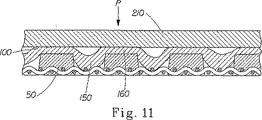
ウェブの一部を成形部材50の開口内に偏向することにより、成形部材50の開口内に形成される結果として生じたピロー150の密度を、成形ウェブ20の残部の密度に比べて低下させることができる。開口内に偏向されていない領域160は、その後、乾燥ドラム200の表面210とロール50c(図1)の間に形成された圧縮ニップ内などの、圧縮用表面210と成形部材50(図11)の間でウェブ20を型押しすることによって圧痕形成されてもよい。圧痕形成される場合、領域160の密度は、ピロー150の密度に対して更により大きい。
By deflecting a portion of the web into the opening of the forming
繊維構造体100の2つの複数のマイクロ領域は、2つの異なる高さで配置されるものと考えられる。本明細書で使用する時、領域の高さは、参照平面(即ち、X−Y平面)からのその距離を指す。便宜上、参照平面を水平なものとして視覚化することができ、参照平面からの高さ距離は垂直である(即ち、Z方向)。構造体100の特定のマイクロ領域の高さは、当該技術分野において周知であるような用途に適する任意の非接触型測定装置を用いて測定してもよい。特に好適な測定装置は、50mmの範囲で0.3×1.2mmのビームサイズを有する非接触型レーザー変位センサ(Laser Displacement Sensor)である。好適な非接触型レーザー変位センサは、アイデック社(Idec Company)により、モデルMX1A/Bとして販売されている。あるいは、当該技術分野において既知であるような接触型スタイラス(stylis)ゲージを、異なる高さを測定するのに利用してもよい。かかるスタイラスゲージは、米国特許第4,300,981号(カーステンズ(Carstens)に発行)に記載されており、この開示は、本明細書に参考として組み込まれる。本発明による繊維構造体100は、圧痕形成領域160が参照平面と接触した状態で、参照平面上に置くことができる。ピロー150は、参照平面から垂直に離れるように延在する。複数のピロー150は、対称的なピロー、非対称的なピロー(図7では参照番号150a)、又はこれらの組み合わせを含み得る。
Two micro-regions of the
マイクロ領域の異なる高さは、深さ又は高さが異なる三次元パターン(図示せず)を有する成形部材50によって形成することもできる。異なる深さ/高さを有するこのような三次元パターンは、成形部材50の予め選択された一部をやすりにかけ、それらの高さを低くすることによって作成することができる。また、硬化性材料を含む成形部材50は、三次元マスクを使用することにより作成することができる。深さ/高さが異なる凹部/凸部を有する三次元マスクを使用することによって、やはり異なる高さを有する対応する枠組み60を形成することができる。高さが異なる表面を形成する他の従来技法を、上述の用途に使用することができる。
Different heights of the micro regions can also be formed by the molded
成形部材200を貫通して幾つかのフィラメント又はその一部を押し入れ、故に、結果として生じた繊維構造体にいわゆるピンホールの形成を招き得る真空装置16及び/若しくは17、並びに/又は真空ピックアップシュー15(図1)によって、作成中の繊維構造体に流体圧力差を急激に付与することから生じ得る負の効果を改善するために、成形部材50の裏側52を、微視的な表面の凹凸を形成すべく「非平坦化」することができる。それら表面の凹凸は、成形部材50の裏側52と抄紙機器の表面(例えば、真空装置の表面など)の間に真空シールが形成されるのを防ぎ、これにより、それら間に「漏れ」を創出し、故に空気通過乾燥プロセスにおける真空圧の印加がもたらす望ましくない結果を緩和するので、成形部材50の幾つかの実施形態においては有益であり得る。かかる漏れを創出する他の方法は、米国特許第5,718,806号、米国特許第5,741,402号、米国特許第5,744,007号、米国特許第5,776,311号及び米国特許第5,885,421号に開示されており、これらの開示は、本明細書に参考として組み込まれる。
漏れは、米国特許第5,624,790号、米国特許第5,554,467号、米国特許第5,529,664号、米国特許第5,514,523号及び米国特許第5,334,289号に記載されるような、いわゆる「光透過差技法」を用いて創出され得、これらの開示は、本明細書に参考として組み込まれる。成形部材は、不透明な一部を有する補強要素に感光性樹脂のコーティングを適用し、次いで透明領域及び不透明領域を有するマスクを通して、また補強要素を通して、そのコーティングを活性化波長の光に曝露することにより作成され得る。 Leaks were found in U.S. Patent No. 5,624,790, U.S. Patent No. 5,554,467, U.S. Patent No. 5,529,664, U.S. Patent No. 5,514,523 and U.S. Patent No. 5,334. 289 may be created using the so-called “light transmission difference technique”, as described in US Pat. No. 289, the disclosures of which are incorporated herein by reference. The molded member applies a photosensitive resin coating to a reinforcing element having an opaque portion, and then exposes the coating to light of an activating wavelength through a mask having transparent and opaque regions and through the reinforcing element. Can be created.
裏側表面の凹凸を創り出す別の方法は、米国特許第5,364,504号、米国特許第5,260,171号及び米国特許第5,098,522号に記載されるような非平坦化されたフォーミング表面又は非平坦化されたバリアフィルムの使用を含み、これらの開示は、本明細書に参考として組み込まれる。成形部材は、補強要素が非平坦化表面上を移動する間に、補強要素上にくまなく感光性樹脂をキャストし、次いで、透明領域及び不透明領域を有するマスクを通してそのコーティングを活性化波長の光に曝露することによって作成され得る。 Another method of creating backside surface irregularities is non-planarized as described in US Pat. No. 5,364,504, US Pat. No. 5,260,171 and US Pat. No. 5,098,522. The disclosure of which is incorporated herein by reference. The molded member casts the photosensitive resin all over the reinforcing element as the reinforcing element moves over the non-planarized surface, and then activates the coating through a mask having transparent and opaque regions to activate light of the wavelength. Can be created by exposure to.
この方法は、初期ウェブ10(又は成形ウェブ20)が、成形部材と共に移動するエンドレスバンドを構成する可撓性の材料シートで覆われ、それにより初期ウェブ10が、成形部材と可撓性材料シートの間に一定期間挟まれるという任意の工程を含んでもよい。可撓性材料シートは、成形部材の空気透過性よりも低い空気透過性を有し得、幾つかの実施形態においては空気不透過性であり得る。成形部材50を通して流体圧力差を可撓性シートに付与することにより、可撓性シートの少なくとも一部が、成形部材50の三次元パターンに向かって、及び場合によってはその中へ偏向され、それにより、成形部材50上に配置されたウェブの一部が押入されて、成形部材50の三次元パターンと密接に適合する。米国特許第5,893,965号(この開示は、本明細書に参考として組み込まれる)は、可撓性材料シートを利用する方法及び装置の主要な構成を記載している。
In this method, the initial web 10 (or molded web 20) is covered with a flexible material sheet that forms an endless band that moves with the molded member, whereby the
流体圧力差に加えて、又はその代わりに、機械的圧力も、本発明の繊維構造体100の微視的な三次元パターンの形成を促進するために使用することができる。かかる機械的圧力は、例えば、ロールの表面又はバンド(図示せず)の表面を含む任意の好適な圧縮用表面により創出され得る。圧縮用表面は平滑であり得るか、又はそれ自体の三次元パターンを有し得る。後者の例では、圧縮用表面をエンボス加工装置として使用することができ、これにより、成形部材50の三次元パターンと連携して、又はそれとは独立して、作成中の繊維構造体100内に凸部及び/又は凹部の独特なマイクロパターンを形成する。更に、例えば柔軟材及びインクなどの様々な添加剤を作成中の繊維構造体に堆積させるために、圧縮用表面を使用することができる。様々な添加剤を作成中の繊維構造体に直接又は間接的に堆積させるために、例えば、インクロール又はスプレー装置又はシャワー(図示せず)などの様々な従来技法を使用してもよい。
In addition to or instead of the fluid pressure differential, mechanical pressure can also be used to facilitate the formation of a microscopic three-dimensional pattern of the
ウェブ内の合成繊維の少なくとも一部を再分配する工程は、ウェブ形成工程の後に達成されてもよい。最も典型的には、再分配は、例えば加熱装置90及び/又は乾燥表面210によって、例えば乾燥ドラムのフード(例えば、ヤンキーの乾燥フードなど)と結合している図1に示す加熱装置80によって、ウェブが成形部材50上に配置されている間に起こり得る。いずれの例においても、矢印は繊維ウェブ上に衝突する熱ガスの方向を概略的に示す。再分配は、合成繊維の少なくとも一部を溶融させるか、ないしは別の方法でそれらの構成を変更させることにより達成され得る。理論に束縛されるものではないが、約230℃〜約300℃の範囲の再分配温度では、高温の影響下での縮み及び/又は少なくとも部分的な溶融の結果として、ウェブを構成する合成繊維の少なくとも一部は移動し得ると考えられている。図8及び図9は、初期ウェブ10における合成繊維の再分配を概略的に例証することを意図する。図8において、代表的な合成繊維101、102、103及び104が、ウェブに熱が印加される前に、ウェブの全体にわたってランダムに分配されていることが示されている。図9では、熱Tがウェブに印加され、これにより合成繊維101〜104が、少なくとも部分的に溶融、縮む、ないしは別の方法で自らの形状を変え、故にウェブ内での合成繊維の再分配を引き起こす。
Redistributing at least a portion of the synthetic fibers within the web may be accomplished after the web forming step. Most typically, the redistribution is performed by, for example, the
理論に束縛されるものではないが、合成繊維は、2つの現象のうちの少なくとも1つの影響下で、十分に高い温度が印加された後に移動することができると考えられている。合成(ポリマー)繊維を溶融するのに十分な程温度が高い場合、結果として生じる液体ポリマーは、表面張力に起因して自らの表面積/質量を最小にし、あまり熱の影響を受けない繊維部分の端部で球体のような形状(図9では102、104)を形成する傾向を有する。一方、温度が溶融点よりも低い場合、残留応力が高い繊維は、応力が繊維の縮み又はコイル化により緩和される点まで軟化する。これは、ポリマー分子が典型的には非線形にコイル化した状態でいることを好むために起こると考えられている。それらの製造中に非常に延伸され、次いで冷却された繊維は、準安定性形状に延伸されたポリマー分子からなる。その後の加熱により、分子、ひいては繊維は自由エネルギーが最小のコイル化状態に戻る。 Without being bound by theory, it is believed that synthetic fibers can move after a sufficiently high temperature is applied under the influence of at least one of two phenomena. If the temperature is high enough to melt the synthetic (polymer) fibers, the resulting liquid polymer will minimize its surface area / mass due to surface tension and will be less susceptible to heat effects. It tends to form a sphere-like shape (102, 104 in FIG. 9) at the end. On the other hand, if the temperature is lower than the melting point, the fiber with high residual stress softens to the point where the stress is relaxed by fiber shrinkage or coiling. This is believed to occur because polymer molecules typically prefer to be in a non-linear coiled state. Fibers that are highly drawn during their manufacture and then cooled are composed of polymer molecules drawn into a metastable shape. Subsequent heating returns the molecules, and thus the fibers, to a coiled state with minimal free energy.
合成繊維が少なくとも部分的に溶融又は軟化すると、それらは、セルロース繊維であれ、他の合成繊維であれ、隣接する繊維と共接合可能になる。理論に束縛されるものではないが、繊維の共接合は、機械的共接合と、化学的共接合とを含み得る。化学的な共接合は、少なくとも2つの隣接する繊維が、個々の共接合繊維のアイデンティティが共接合区域にて実質的に失われるように分子レベルで共に接合される時に起こる。繊維の機械的な共接合は、1つの繊維が隣接する繊維の形状に単に適合する時に起こり、共接合繊維間に化学反応はない。図12は、機械的共接合の1つの実施形態を概略的に示し、繊維111は、隣接する合成繊維112により物理的に「取り込まれて」いる。繊維111は合成繊維又はセルロース繊維であり得る。図12に示す例において、合成繊維112は、コア112a及びシース、又はシェル、112bを含む2成分構造体を含み、コア112aの溶融温度は、シース112bの溶融温度よりも大きく、故に、加熱すると、シース112bのみが溶融し、一方コア112aはその完全性を保持する。2つ以上の構成成分を含む多成分繊維が本発明で使用可能であることが理解される。
When the synthetic fibers are at least partially melted or softened, they can be co-joined with adjacent fibers, whether cellulose fibers or other synthetic fibers. Without being bound by theory, fiber co-bonding can include mechanical co-bonding and chemical co-bonding. Chemical co-bonding occurs when at least two adjacent fibers are bonded together at the molecular level such that the identity of the individual co-bonded fibers is substantially lost in the co-bonded area. Mechanical co-bonding of fibers occurs when one fiber simply conforms to the shape of adjacent fibers and there is no chemical reaction between the co-bonded fibers. FIG. 12 schematically illustrates one embodiment of mechanical co-bonding, where fibers 111 are physically “entrapped” by adjacent
ウェブにおける合成繊維の加熱は、成形部材50の流体透過性区域に対応する複数のマイクロ領域を加熱することにより達成され得る。例えば、加熱装置90からの熱ガスは、図1に概略的に示すように、ウェブを通って押入され得る。プレドライヤー(図示せず)も、繊維の再分配を行うためのエネルギー源として使用され得る。プロセスに応じて、熱ガスの流れの方向を、図1に示す方向に対して反転することができ、故に熱ガスは成形部材を通ってウェブを貫通する(図9)。次いで、成形部材50の流体透過性区域に配置されるウェブの「ピロー」部分150は、主に高温ガスによって影響される。ウェブの残部は、成形部材50により熱ガスから遮蔽される。従って、共接合繊維は、主としてウェブのピロー部分150において共接合される。プロセスに応じて、合成繊維は、相対的に高い密度を有する複数のマイクロ領域が非ランダム反復パターンの複数の合成繊維と位置合せされるように再分配され得る。あるいは、合成繊維は、相対的に低い密度を有する複数のマイクロ領域が非ランダム反復パターンの複数の合成繊維と位置合せされるように再分配され得る。
Heating of the synthetic fibers in the web can be accomplished by heating a plurality of microregions corresponding to the fluid permeable areas of the molded
合成繊維は本明細書に記載されるように再分配されるが、セルロース繊維のランダムな分配は熱に影響されない。故に、結果として生じた繊維構造体100は、繊維構造体の全体にわたってランダムに分配された複数のセルロース繊維と、繊維構造体の全体にわたって非ランダム反復パターンで分配された複数の合成繊維とを含む。図10は繊維構造体100の1つの実施形態を概略的に示し、セルロース繊維110は、構造体の全体にわたってランダムに分配され、合成繊維120は、非ランダム反復パターンで再分配される。
Synthetic fibers are redistributed as described herein, but the random distribution of cellulose fibers is not affected by heat. Thus, the resulting
繊維構造体100は、相対的に高い坪量を有する複数のマイクロ領域と、相対的に低い坪量を有する複数の領域とを有してもよい。複数の合成繊維の非ランダム反復パターンは、相対的に高い坪量を有するマイクロ領域と位置合せされてもよい。あるいは、複数の合成繊維の非ランダム反復パターンは、相対的に低い坪量を有するマイクロ領域と位置合せされてもよい。合成繊維の非ランダム反復パターンは、本明細書中で定義されるように、実質的に連続的なパターン、実質的に半連続的なパターン、隔離されたパターン、又はこれらの任意の組み合わせからなる群から選択してもよい。
The
合成繊維の材料は、ポリオレフィン類、ポリエステル類、ポリアミド類、ポリヒドロキシアルカノエート類、多糖類及びこれらの任意の組み合わせからなる群から選択することができる。より具体的には、合成繊維の材料は、ポリ(エチレンテレフタレート)、ポリ(ブチレンテレフタレート)、ポリ(1,4−シクロヘキシレンジメチレンテレフタレート)、イソフタル酸コポリマー類、エチレングリコールコポリマー類、ポリオレフィン類、ポリ(乳酸)、ポリ(ヒドロキシエーテルエステル)ポリ(ヒドロキシエーテルアミド)、ポリカプロラクトン、ポリエステルアミド、多糖類、及びこれらの任意の組み合わせからなる群から選択され得る。 The synthetic fiber material can be selected from the group consisting of polyolefins, polyesters, polyamides, polyhydroxyalkanoates, polysaccharides and any combination thereof. More specifically, synthetic fiber materials include poly (ethylene terephthalate), poly (butylene terephthalate), poly (1,4-cyclohexylenedimethylene terephthalate), isophthalic acid copolymers, ethylene glycol copolymers, polyolefins, It may be selected from the group consisting of poly (lactic acid), poly (hydroxy ether ester) poly (hydroxy ether amide), polycaprolactone, polyester amide, polysaccharide, and any combination thereof.
所望であれば、初期ウェブ又は成形ウェブは、坪量差を有してもよい。繊維構造体100において坪量差があるマイクロ領域を創出する1つの方法は、共に譲渡された米国特許第5,245,025号、米国特許第5,277,761号、米国特許第5,443,691号、米国特許第5,503,715号、米国特許第5,527,428号、米国特許第5,534,326号、米国特許第5,614,061号及び米国特許第5,654,076号(これらの開示は、本明細書に参考として組み込まれる)に記載されるように、図5及び図6に主として示される構造体、即ち流体透過性の補強要素に接合された複数の隔離された突出部を含むこの構造体を含むフォーミング部材上に初期ウェブ10を形成することを含む。かかるフォーミング部材上に形成された初期ウェブ10は、相対的に高い坪量を有する複数のマイクロ領域と、相対的に低い坪量を有する複数のマイクロ領域とを有する。
If desired, the initial web or molded web may have a basis weight difference. One method of creating a micro-area with a difference in basis weight in the
その方法の別の実施形態において、再分配工程は、2つの工程で達成されてもよい。例として、まず、繊維ウェブが成形部材上に配置される間に、例えばウェブのピローを通して熱ガスを吹きつけることにより、合成繊維を再分配することができ、これにより、合成繊維は、例えば、相対的に密度が低い複数のマイクロ領域が複数の合成繊維の非ランダム反復パターンと位置合せされるような第一のパターンに従って再分配される。次いで、ウェブを別の成形部材に移送することができ、合成繊維は第二のパターンに従って更に再分配され得る。 In another embodiment of the method, the redistribution step may be accomplished in two steps. By way of example, synthetic fibers can be redistributed, for example, by blowing hot gas through the web's pillows while the fiber web is first placed on the molded member, so that the synthetic fibers are, for example, A plurality of relatively low density micro-regions are redistributed according to a first pattern that is aligned with a non-random repeating pattern of synthetic fibers. The web can then be transferred to another forming member and the synthetic fibers can be further redistributed according to a second pattern.
繊維構造体100は、所望により、当該技術分野において既知であるように短縮されてもよい。短縮は、例えば乾燥ドラム200(図1)の表面210などの剛直表面から構造体100をクレーピングすることによって達成することができる。クレーピングは、これもまた当該技術分野において周知であるように、ドクターブレード250を使って達成することができる。例えば、クレーピングは、米国特許第4,919,756号(ソーダイ(Sawdai)、1992年4月24日発行)に従って達成されてもよく、この開示は、本明細書に参考として組み込まれる。あるいは、又は更に、短縮は、上述のようなマイクロ収縮を通して達成されてもよい。
The
短縮される繊維構造体100は、典型的には、機械横方向よりも機械方向により延伸性があり、短縮プロセスにより形成されたヒンジ線の周りで容易に曲げられ、このヒンジ線は、概ね機械横方向に、即ち繊維構造体100の幅に沿って延在する。クレーピングされていない及び/又は別の方法で短縮される繊維構造体100は、本発明の範囲内であると想定される。
The shortened
本発明の繊維構造体100を用いて様々な製品を作成することができる。結果として生じた製品は、空気、油及び水用フィルタ;掃除機用フィルタ;炉用フィルタ;フェイスマスク;コーヒーフィルタ、ティー又はコーヒーバッグ;断熱材及び遮音材;おむつ、女性用パッド及び失禁物品などの単回使用型衛生製品用の不織布;微小繊維又は通気性布地のような吸水性及び着用の柔軟性を改良するための生分解性織物布地;粉塵の回収及び除去のための静電的に帯電した構造ウェブ;補強材、及び包装紙、筆記用紙、新聞印刷用紙、ダンボールのような硬質紙用ウェブ、及びトイレットペーパー、紙タオル、ナプキン及びフェイシャルティッシュなどの紙のティッシュ等級用ウェブ;外科用カーテン、創傷包帯、包帯及び皮膚貼付剤のような医療用途での使用を見出し得る。繊維構造体はまた、特定用途のための臭い吸収剤、シロアリ忌避剤、殺虫剤、殺鼠剤などを包含してもよい。結果として生じた製品は、水及び油を吸収し、油若しくは水こぼしの清掃、又は農業若しくは園芸用途のための制御された水保持及び放出での使用を見出し得る。
Various products can be made using the
Claims (8)
(a)前記繊維構造体の全体にわたってランダムに分配された複数のセルロース繊維と、
(b)前記繊維構造体が複数の合成繊維の異なる坪量の2つ以上の領域を有するように前記繊維構造体の全体にわたって分配された前記複数の合成繊維と、
を含み、
ここで、前記繊維構造体が、相対的に密度が高い複数のマイクロ領域と、相対的に密度が低い複数のマイクロ領域とを含み、前記相対的に密度が高い複数のマイクロ領域の少なくとも1つが、前記複数の合成繊維の相対的に坪量の高い領域と位置合せされ、前記複数の合成繊維が、前記繊維構造体の全体にわたって非ランダム反復パターンで分配され、前記非ランダム反復パターンが、連続的な網状パターン、半連続的なパターン、隔離されたパターン及びこれらの任意の組み合わせからなる群から選択される単一繊維構造体。Single fiber structure:
(A) a plurality of cellulose fibers randomly distributed throughout the fibrous structure;
(B) the plurality of synthetic fibers distributed throughout the fiber structure such that the fiber structure has two or more regions of different basis weights of the plurality of synthetic fibers;
Including
Here, the fibrous structure, a relatively high density plurality of micro regions, and a relatively low density plurality of micro regions, the relatively density at least one of the plurality of high micro regions the plurality of the relatively basis weight regions of high and alignment of synthetic fibers, wherein the plurality of synthetic fibers, said distributed in a non-random repeating pattern throughout the fibrous structure, the non-random repeating pattern, continuous A single fiber structure selected from the group consisting of a typical reticulated pattern, a semi-continuous pattern, an isolated pattern, and any combination thereof .
Applications Claiming Priority (2)
| Application Number | Priority Date | Filing Date | Title |
|---|---|---|---|
| US10/360,038 US7052580B2 (en) | 2003-02-06 | 2003-02-06 | Unitary fibrous structure comprising cellulosic and synthetic fibers |
| PCT/US2004/003335 WO2004072371A1 (en) | 2003-02-06 | 2004-02-04 | Unitary fibrous structure comprising cellulosic and synthetic fibers and process for making same |
Publications (2)
| Publication Number | Publication Date |
|---|---|
| JP2006514175A JP2006514175A (en) | 2006-04-27 |
| JP4382043B2 true JP4382043B2 (en) | 2009-12-09 |
Family
ID=32823921
Family Applications (1)
| Application Number | Title | Priority Date | Filing Date |
|---|---|---|---|
| JP2005518378A Expired - Lifetime JP4382043B2 (en) | 2003-02-06 | 2004-02-04 | Single fiber structure containing cellulose fiber and synthetic fiber and method for producing the same |
Country Status (9)
| Country | Link |
|---|---|
| US (2) | US7052580B2 (en) |
| EP (1) | EP1590530B1 (en) |
| JP (1) | JP4382043B2 (en) |
| CN (2) | CN1745214B (en) |
| AU (1) | AU2004211617B2 (en) |
| CA (1) | CA2514603C (en) |
| ES (1) | ES2392252T3 (en) |
| MX (1) | MXPA05007931A (en) |
| WO (1) | WO2004072371A1 (en) |
Families Citing this family (41)
| Publication number | Priority date | Publication date | Assignee | Title |
|---|---|---|---|---|
| US20040157524A1 (en) * | 2003-02-06 | 2004-08-12 | The Procter & Gamble Company | Fibrous structure comprising cellulosic and synthetic fibers |
| US7052580B2 (en) * | 2003-02-06 | 2006-05-30 | The Procter & Gamble Company | Unitary fibrous structure comprising cellulosic and synthetic fibers |
| US7067038B2 (en) * | 2003-02-06 | 2006-06-27 | The Procter & Gamble Company | Process for making unitary fibrous structure comprising randomly distributed cellulosic fibers and non-randomly distributed synthetic fibers |
| EP1757728B1 (en) * | 2005-08-26 | 2008-11-19 | Voith Patent GmbH | Polymer particles mixed with fibers, method of making, and products such as press fabrics made therefrom |
| WO2007123704A2 (en) * | 2006-03-31 | 2007-11-01 | The Procter & Gamble Company | Nonwoven fibrous structure comprising synthetic fibers and hydrophilizing agent |
| EP2001425B1 (en) * | 2006-03-31 | 2011-09-14 | The Procter & Gamble Company | Absorbent article comprising a fibrous structure comprising synthetic fibers and a hydrophilizing agent |
| MX2008011673A (en) * | 2006-03-31 | 2008-09-22 | Procter & Gamble | Method for forming a fibrous structure comprising synthetic fibers and hydrophilizing agents. |
| US7771648B2 (en) * | 2006-04-06 | 2010-08-10 | The Procter & Gamble Company | One-dimensional continuous molded element |
| US20070254145A1 (en) * | 2006-05-01 | 2007-11-01 | The Procter & Gamble Company | Molded elements |
| DE102006041772B4 (en) * | 2006-09-04 | 2010-07-01 | Carl Freudenberg Kg | Infusion bag and use of the same |
| US7799411B2 (en) * | 2006-10-31 | 2010-09-21 | The Procter & Gamble Company | Absorbent paper product having non-embossed surface features |
| US20080099170A1 (en) * | 2006-10-31 | 2008-05-01 | The Procter & Gamble Company | Process of making wet-microcontracted paper |
| US9315929B2 (en) | 2007-09-28 | 2016-04-19 | The Procter & Gamble Company | Non-wovens with high interfacial pore size and method of making same |
| US20090136722A1 (en) * | 2007-11-26 | 2009-05-28 | Dinah Achola Nyangiro | Wet formed fibrous structure product |
| US8845935B2 (en) * | 2008-03-12 | 2014-09-30 | Novartis Ag | Method for cast molding contact lenses |
| CN102056985B (en) | 2008-05-06 | 2014-02-19 | 梅塔玻利克斯公司 | Biodegradable polyester blends |
| US20090280297A1 (en) * | 2008-05-07 | 2009-11-12 | Rebecca Howland Spitzer | Paper product with visual signaling upon use |
| US20100119779A1 (en) * | 2008-05-07 | 2010-05-13 | Ward William Ostendorf | Paper product with visual signaling upon use |
| EP2539507A1 (en) | 2010-02-26 | 2013-01-02 | The Procter & Gamble Company | Fibrous structure product with high wet bulk recovery |
| CA2820287C (en) | 2010-12-08 | 2019-06-04 | Buckeye Technologies Inc. | Dispersible nonwoven wipe material |
| US9439549B2 (en) * | 2010-12-08 | 2016-09-13 | Georgia-Pacific Nonwovens LLC | Dispersible nonwoven wipe material |
| CN102320074B (en) * | 2011-09-14 | 2014-05-28 | 黄俊腾 | Manufacturing method of environment-friendly inorganic paper |
| US9458574B2 (en) | 2012-02-10 | 2016-10-04 | The Procter & Gamble Company | Fibrous structures |
| WO2014004939A1 (en) | 2012-06-29 | 2014-01-03 | The Procter & Gamble Company | Textured fibrous webs, apparatus and methods for forming textured fibrous webs |
| US9475930B2 (en) | 2012-08-17 | 2016-10-25 | Metabolix, Inc. | Biobased rubber modifiers for polymer blends |
| US8815054B2 (en) | 2012-10-05 | 2014-08-26 | The Procter & Gamble Company | Methods for making fibrous paper structures utilizing waterborne shape memory polymers |
| JP2014210596A (en) * | 2013-04-18 | 2014-11-13 | ユニチカトレーディング株式会社 | Favorite beverage extract bag |
| EP3004225A1 (en) | 2013-05-30 | 2016-04-13 | Metabolix, Inc. | Recyclate blends |
| WO2015149029A1 (en) | 2014-03-27 | 2015-10-01 | Metabolix, Inc. | Highly filled polymer systems |
| US10132042B2 (en) | 2015-03-10 | 2018-11-20 | The Procter & Gamble Company | Fibrous structures |
| EP3023084B1 (en) | 2014-11-18 | 2020-06-17 | The Procter and Gamble Company | Absorbent article and distribution material |
| US10765570B2 (en) | 2014-11-18 | 2020-09-08 | The Procter & Gamble Company | Absorbent articles having distribution materials |
| US10517775B2 (en) | 2014-11-18 | 2019-12-31 | The Procter & Gamble Company | Absorbent articles having distribution materials |
| KR20180064535A (en) | 2015-11-03 | 2018-06-14 | 킴벌리-클라크 월드와이드, 인크. | Paper tissue with high bulk and low lint |
| WO2017156203A1 (en) | 2016-03-11 | 2017-09-14 | The Procter & Gamble Company | A three-dimensional substrate comprising a tissue layer |
| US11255051B2 (en) | 2017-11-29 | 2022-02-22 | Kimberly-Clark Worldwide, Inc. | Fibrous sheet with improved properties |
| SE543939C2 (en) | 2018-05-15 | 2021-09-28 | Albany Int Corp | A method and a machine for making tissue paper |
| GB2590316B (en) | 2018-07-25 | 2022-06-01 | Kimberly Clark Co | Process for making three-dimensional foam-laid nonwovens |
| CN109371735A (en) * | 2018-11-10 | 2019-02-22 | 长沙云聚汇科技有限公司 | A kind of surface layer antibacterial nonwoven cloth processing unit (plant) |
| CN109338785A (en) * | 2018-11-10 | 2019-02-15 | 长沙云聚汇科技有限公司 | A kind of nonwoven paper cloth processing unit (plant) |
| CA3064406C (en) | 2018-12-10 | 2023-03-07 | The Procter & Gamble Company | Fibrous structures |
Family Cites Families (95)
| Publication number | Priority date | Publication date | Assignee | Title |
|---|---|---|---|---|
| US3116199A (en) * | 1961-07-19 | 1963-12-31 | Fmc Corp | Water-laid web |
| NL6702029A (en) * | 1966-07-26 | 1968-01-29 | ||
| GB1279210A (en) * | 1970-05-26 | 1972-06-28 | Wiggins Teape Res Dev | Non-woven fibrous material |
| US3879257A (en) * | 1973-04-30 | 1975-04-22 | Scott Paper Co | Absorbent unitary laminate-like fibrous webs and method for producing them |
| US4012281A (en) * | 1975-03-04 | 1977-03-15 | Johnson & Johnson | Wet laid laminate and method of manufacturing the same |
| US3994771A (en) * | 1975-05-30 | 1976-11-30 | The Procter & Gamble Company | Process for forming a layered paper web having improved bulk, tactile impression and absorbency and paper thereof |
| GB1573114A (en) | 1976-12-08 | 1980-08-13 | Ici Ltd | Paper |
| US4300981A (en) * | 1979-11-13 | 1981-11-17 | The Procter & Gamble Company | Layered paper having a soft and smooth velutinous surface, and method of making such paper |
| US4440697A (en) * | 1980-07-11 | 1984-04-03 | Yamaha Hatsudoki Kabushiki Kaisha | Carburetor |
| US4486268A (en) * | 1981-05-04 | 1984-12-04 | Kimberly-Clark Corporation | Air/water hybrid former |
| US4487796A (en) * | 1981-07-02 | 1984-12-11 | Kimberly-Clark Corporation | Laminated, creped tissue and method of manufacture |
| IE53968B1 (en) | 1981-11-24 | 1989-04-26 | Kimberly Clark Ltd | Microfibre web product |
| US4440597A (en) | 1982-03-15 | 1984-04-03 | The Procter & Gamble Company | Wet-microcontracted paper and concomitant process |
| US4529480A (en) * | 1983-08-23 | 1985-07-16 | The Procter & Gamble Company | Tissue paper |
| US4741941A (en) * | 1985-11-04 | 1988-05-03 | Kimberly-Clark Corporation | Nonwoven web with projections |
| US5277761A (en) | 1991-06-28 | 1994-01-11 | The Procter & Gamble Company | Cellulosic fibrous structures having at least three regions distinguished by intensive properties |
| US4808467A (en) * | 1987-09-15 | 1989-02-28 | James River Corporation Of Virginia | High strength hydroentangled nonwoven fabric |
| US4919756A (en) | 1988-08-26 | 1990-04-24 | The Procter & Gamble Company | Method of and apparatus for compensatingly adjusting doctor blade |
| DE69020598T2 (en) * | 1989-02-17 | 1996-04-04 | Matsushita Electric Ind Co Ltd | Tuner for tuning to selected stations. |
| DE69007566T2 (en) * | 1989-07-18 | 1994-06-30 | Mitsui Petrochemical Ind | Nonwoven fabric and process for its manufacture. |
| CA2155222C (en) | 1990-06-29 | 1997-11-11 | Paul Dennis Trokhan | Process for making absorbent paper web |
| US5260171A (en) | 1990-06-29 | 1993-11-09 | The Procter & Gamble Company | Papermaking belt and method of making the same using a textured casting surface |
| US5098522A (en) | 1990-06-29 | 1992-03-24 | The Procter & Gamble Company | Papermaking belt and method of making the same using a textured casting surface |
| US5167765A (en) * | 1990-07-02 | 1992-12-01 | Hoechst Celanese Corporation | Wet laid bonded fibrous web containing bicomponent fibers including lldpe |
| US5167764A (en) * | 1990-07-02 | 1992-12-01 | Hoechst Celanese Corporation | Wet laid bonded fibrous web |
| US5094717A (en) * | 1990-11-15 | 1992-03-10 | James River Corporation Of Virginia | Synthetic fiber paper having a permanent crepe |
| US5204173A (en) * | 1990-11-29 | 1993-04-20 | Dvsg Holding Gmbh | Paperboard product and process |
| CA2048905C (en) * | 1990-12-21 | 1998-08-11 | Cherie H. Everhart | High pulp content nonwoven composite fabric |
| US5178729A (en) * | 1991-01-15 | 1993-01-12 | James River Corporation Of Virginia | High purity stratified tissue and method of making same |
| US5245025A (en) * | 1991-06-28 | 1993-09-14 | The Procter & Gamble Company | Method and apparatus for making cellulosic fibrous structures by selectively obturated drainage and cellulosic fibrous structures produced thereby |
| EP0575601A1 (en) | 1992-01-21 | 1993-12-29 | James River Corporation Of Virginia | Reinforced absorbent paper |
| JP3135991B2 (en) * | 1992-06-18 | 2001-02-19 | 本田技研工業株式会社 | Fuel cell and fuel cell stack tightening method |
| TW244342B (en) * | 1992-07-29 | 1995-04-01 | Procter & Gamble | |
| US5405682A (en) * | 1992-08-26 | 1995-04-11 | Kimberly Clark Corporation | Nonwoven fabric made with multicomponent polymeric strands including a blend of polyolefin and elastomeric thermoplastic material |
| CA2105026C (en) * | 1993-04-29 | 2003-12-16 | Henry Louis Griesbach Iii | Shaped nonwoven fabric and method for making the same |
| US5405499A (en) * | 1993-06-24 | 1995-04-11 | The Procter & Gamble Company | Cellulose pulps having improved softness potential |
| US5607551A (en) | 1993-06-24 | 1997-03-04 | Kimberly-Clark Corporation | Soft tissue |
| US5795440A (en) | 1993-12-20 | 1998-08-18 | The Procter & Gamble Company | Method of making wet pressed tissue paper |
| US5861082A (en) | 1993-12-20 | 1999-01-19 | The Procter & Gamble Company | Wet pressed paper web and method of making the same |
| US5776307A (en) | 1993-12-20 | 1998-07-07 | The Procter & Gamble Company | Method of making wet pressed tissue paper with felts having selected permeabilities |
| CZ183596A3 (en) | 1993-12-20 | 1996-11-13 | Procter & Gamble | Wet pressed paper structure and process for producing thereof |
| US5904811A (en) | 1993-12-20 | 1999-05-18 | The Procter & Gamble Company | Wet pressed paper web and method of making the same |
| US5429686A (en) | 1994-04-12 | 1995-07-04 | Lindsay Wire, Inc. | Apparatus for making soft tissue products |
| CA2134594A1 (en) | 1994-04-12 | 1995-10-13 | Kimberly-Clark Worldwide, Inc. | Method for making soft tissue products |
| CA2142805C (en) | 1994-04-12 | 1999-06-01 | Greg Arthur Wendt | Method of making soft tissue products |
| US5496624A (en) | 1994-06-02 | 1996-03-05 | The Procter & Gamble Company | Multiple layer papermaking belt providing improved fiber support for cellulosic fibrous structures, and cellulosic fibrous structures produced thereby |
| US5500277A (en) | 1994-06-02 | 1996-03-19 | The Procter & Gamble Company | Multiple layer, multiple opacity backside textured belt |
| US5569358A (en) | 1994-06-01 | 1996-10-29 | James River Corporation Of Virginia | Imprinting felt and method of using the same |
| US5814190A (en) | 1994-06-29 | 1998-09-29 | The Procter & Gamble Company | Method for making paper web having both bulk and smoothness |
| US5549790A (en) | 1994-06-29 | 1996-08-27 | The Procter & Gamble Company | Multi-region paper structures having a transition region interconnecting relatively thinner regions disposed at different elevations, and apparatus and process for making the same |
| US5556509A (en) * | 1994-06-29 | 1996-09-17 | The Procter & Gamble Company | Paper structures having at least three regions including a transition region interconnecting relatively thinner regions disposed at different elevations, and apparatus and process for making the same |
| BR9607604A (en) | 1995-02-15 | 1998-06-09 | Procter & Gamble | Method of applying a photosensitive resin to a substrate for papermaking |
| US5629052A (en) | 1995-02-15 | 1997-05-13 | The Procter & Gamble Company | Method of applying a curable resin to a substrate for use in papermaking |
| US5516580A (en) | 1995-04-05 | 1996-05-14 | Groupe Laperriere Et Verreault Inc. | Cellulosic fiber insulation material |
| US5538595A (en) | 1995-05-17 | 1996-07-23 | The Proctor & Gamble Company | Chemically softened tissue paper products containing a ploysiloxane and an ester-functional ammonium compound |
| FR2738125B1 (en) * | 1995-08-30 | 1998-03-06 | Oreal | PACKAGING KIT FOR MASCARA |
| US5693187A (en) | 1996-04-30 | 1997-12-02 | The Procter & Gamble Company | High absorbance/low reflectance felts with a pattern layer |
| US5830321A (en) | 1997-01-29 | 1998-11-03 | Kimberly-Clark Worldwide, Inc. | Method for improved rush transfer to produce high bulk without macrofolds |
| US5718806A (en) | 1996-09-03 | 1998-02-17 | The Procter & Gamble Company | Vacuum apparatus having flow management device for controlling the rate of application of vacuum pressure in a through air drying papermaking process |
| US5776311A (en) | 1996-09-03 | 1998-07-07 | The Procter & Gamble Company | Vacuum apparatus having transitional area for controlling the rate of application of vacuum in a through air drying papermaking process |
| US5885421A (en) | 1996-09-03 | 1999-03-23 | The Procter & Gamble Company | Vacuum apparatus for having textured clothing for controlling rate of application of vacuum pressure in a through air drying papermaking process |
| US5741402A (en) | 1996-09-03 | 1998-04-21 | The Procter & Gamble Company | Vacuum apparatus having plurality of vacuum sections for controlling the rate of application of vacuum pressure in a through air drying papermaking process |
| US5744007A (en) | 1996-09-03 | 1998-04-28 | The Procter & Gamble Company | Vacuum apparatus having textured web-facing surface for controlling the rate of application of vacuum pressure in a through air drying papermaking process |
| US20020007169A1 (en) * | 1996-12-06 | 2002-01-17 | Weyerhaeuser Company | Absorbent composite having improved surface dryness |
| ATE258851T1 (en) * | 1996-12-06 | 2004-02-15 | Weyerhaeuser Co | ONE-PIECE COMPOSITE LAMINATE |
| US6017418A (en) * | 1996-12-23 | 2000-01-25 | Fort James Corporation | Hydrophilic, humectant, soft, pliable, absorbent paper and method for its manufacture |
| US5990377A (en) | 1997-03-21 | 1999-11-23 | Kimberly-Clark Worldwide, Inc. | Dual-zoned absorbent webs |
| US5935880A (en) * | 1997-03-31 | 1999-08-10 | Wang; Kenneth Y. | Dispersible nonwoven fabric and method of making same |
| US6214146B1 (en) * | 1997-04-17 | 2001-04-10 | Kimberly-Clark Worldwide, Inc. | Creped wiping product containing binder fibers |
| US5989682A (en) * | 1997-04-25 | 1999-11-23 | Kimberly-Clark Worldwide, Inc. | Scrim-like paper wiping product and method for making the same |
| US6129815A (en) * | 1997-06-03 | 2000-10-10 | Kimberly-Clark Worldwide, Inc. | Absorbent towel/wiper with reinforced surface and method for producing same |
| US6139686A (en) * | 1997-06-06 | 2000-10-31 | The Procter & Gamble Company | Process and apparatus for making foreshortened cellulsic structure |
| US5893965A (en) | 1997-06-06 | 1999-04-13 | The Procter & Gamble Company | Method of making paper web using flexible sheet of material |
| US6060149A (en) * | 1997-09-12 | 2000-05-09 | The Procter & Gamble Company | Multiple layer wiping article |
| US6103061A (en) * | 1998-07-07 | 2000-08-15 | Kimberly-Clark Worldwide, Inc. | Soft, strong hydraulically entangled nonwoven composite material and method for making the same |
| US6277241B1 (en) * | 1997-11-14 | 2001-08-21 | Kimberly-Clark Worldwide, Inc. | Liquid absorbent base web |
| US5972813A (en) | 1997-12-17 | 1999-10-26 | The Procter & Gamble Company | Textured impermeable papermaking belt, process of making, and process of making paper therewith |
| US6261679B1 (en) * | 1998-05-22 | 2001-07-17 | Kimberly-Clark Worldwide, Inc. | Fibrous absorbent material and methods of making the same |
| AU6265099A (en) | 1998-10-01 | 2000-04-26 | Kimberly-Clark Worldwide, Inc. | Differential basis weight nonwoven webs |
| US6110848A (en) * | 1998-10-09 | 2000-08-29 | Fort James Corporation | Hydroentangled three ply webs and products made therefrom |
| WO2000039394A1 (en) | 1998-12-30 | 2000-07-06 | Kimberly-Clark Worldwide, Inc. | Layered tissue having a long fiber layer with a patterned mass distribution |
| US6241850B1 (en) * | 1999-06-16 | 2001-06-05 | The Procter & Gamble Company | Soft tissue product exhibiting improved lint resistance and process for making |
| US20020180092A1 (en) * | 1999-10-14 | 2002-12-05 | Kimberly-Clark Worldwide, Inc. | Process for making textured airlaid materials |
| US6361654B1 (en) | 2000-04-26 | 2002-03-26 | Kimberly-Clark Worldwide, Inc. | Air knife assisted sheet transfer |
| US6607635B2 (en) * | 2000-05-12 | 2003-08-19 | Kimberly-Clark Worldwide, Inc. | Process for increasing the softness of base webs and products made therefrom |
| US6808595B1 (en) * | 2000-10-10 | 2004-10-26 | Kimberly-Clark Worldwide, Inc. | Soft paper products with low lint and slough |
| US6576090B1 (en) | 2000-10-24 | 2003-06-10 | The Procter & Gamble Company | Deflection member having suspended portions and process for making same |
| CA2394667C (en) * | 2000-11-01 | 2008-07-15 | The Procter & Gamble Company | Multi-layer substrate for a premoistened wipe capable of controlled fluid release |
| DE10106494B4 (en) * | 2001-02-13 | 2005-05-12 | Papierfabrik Schoeller & Hoesch Gmbh & Co. Kg | Self-cleaning and anti-adhesive papers and paper-like materials, process for their preparation and their use |
| MXPA04002297A (en) * | 2001-09-24 | 2004-06-29 | Procter & Gamble | A soft absorbent web material. |
| US20040079500A1 (en) * | 2002-10-18 | 2004-04-29 | Sca Hygiene Products Ab | Absorbent tissue layer |
| US6861380B2 (en) * | 2002-11-06 | 2005-03-01 | Kimberly-Clark Worldwide, Inc. | Tissue products having reduced lint and slough |
| US20040157524A1 (en) * | 2003-02-06 | 2004-08-12 | The Procter & Gamble Company | Fibrous structure comprising cellulosic and synthetic fibers |
| US7067038B2 (en) * | 2003-02-06 | 2006-06-27 | The Procter & Gamble Company | Process for making unitary fibrous structure comprising randomly distributed cellulosic fibers and non-randomly distributed synthetic fibers |
| US7052580B2 (en) * | 2003-02-06 | 2006-05-30 | The Procter & Gamble Company | Unitary fibrous structure comprising cellulosic and synthetic fibers |
-
2003
- 2003-02-06 US US10/360,038 patent/US7052580B2/en not_active Expired - Lifetime
-
2004
- 2004-02-04 MX MXPA05007931A patent/MXPA05007931A/en active IP Right Grant
- 2004-02-04 CA CA002514603A patent/CA2514603C/en not_active Expired - Fee Related
- 2004-02-04 AU AU2004211617A patent/AU2004211617B2/en not_active Ceased
- 2004-02-04 WO PCT/US2004/003335 patent/WO2004072371A1/en active IP Right Grant
- 2004-02-04 JP JP2005518378A patent/JP4382043B2/en not_active Expired - Lifetime
- 2004-02-04 EP EP20040708237 patent/EP1590530B1/en not_active Expired - Lifetime
- 2004-02-04 CN CN2004800033955A patent/CN1745214B/en not_active Expired - Fee Related
- 2004-02-04 CN CN2004800033692A patent/CN1745215B/en not_active Expired - Fee Related
- 2004-02-04 ES ES04708237T patent/ES2392252T3/en not_active Expired - Lifetime
-
2006
- 2006-04-06 US US11/398,844 patent/US7214293B2/en not_active Expired - Lifetime
Also Published As
| Publication number | Publication date |
|---|---|
| MXPA05007931A (en) | 2005-09-30 |
| US7214293B2 (en) | 2007-05-08 |
| US7052580B2 (en) | 2006-05-30 |
| WO2004072371A1 (en) | 2004-08-26 |
| JP2006514175A (en) | 2006-04-27 |
| US20060175030A1 (en) | 2006-08-10 |
| EP1590530A1 (en) | 2005-11-02 |
| CN1745214B (en) | 2010-05-26 |
| CN1745215A (en) | 2006-03-08 |
| CN1745215B (en) | 2010-05-26 |
| CN1745214A (en) | 2006-03-08 |
| ES2392252T3 (en) | 2012-12-07 |
| CA2514603C (en) | 2008-11-18 |
| AU2004211617A1 (en) | 2004-08-26 |
| EP1590530B1 (en) | 2012-08-01 |
| AU2004211617B2 (en) | 2007-07-26 |
| US20040154768A1 (en) | 2004-08-12 |
| CA2514603A1 (en) | 2004-08-26 |
Similar Documents
| Publication | Publication Date | Title |
|---|---|---|
| JP4382043B2 (en) | Single fiber structure containing cellulose fiber and synthetic fiber and method for producing the same | |
| JP4382042B2 (en) | Method for making single fiber structures comprising randomly distributed cellulose fibers and non-randomly distributed synthetic fibers and single fiber structures made thereby | |
| US7045026B2 (en) | Process for making a fibrous structure comprising cellulosic and synthetic fibers | |
| US5776307A (en) | Method of making wet pressed tissue paper with felts having selected permeabilities | |
| US20080099170A1 (en) | Process of making wet-microcontracted paper | |
| AU2004211619B2 (en) | Process for making a fibrous structure comprising cellulosic and synthetic fibers | |
| AU6055499A (en) | High caliper paper and papermaking belt for producing the same | |
| MXPA01003328A (en) | High caliper paper and papermaking belt for producing the same |
Legal Events
| Date | Code | Title | Description |
|---|---|---|---|
| A131 | Notification of reasons for refusal |
Free format text: JAPANESE INTERMEDIATE CODE: A131 Effective date: 20080401 |
|
| A521 | Written amendment |
Free format text: JAPANESE INTERMEDIATE CODE: A523 Effective date: 20080610 |
|
| A131 | Notification of reasons for refusal |
Free format text: JAPANESE INTERMEDIATE CODE: A131 Effective date: 20090428 |
|
| A521 | Written amendment |
Free format text: JAPANESE INTERMEDIATE CODE: A523 Effective date: 20090713 |
|
| TRDD | Decision of grant or rejection written | ||
| A01 | Written decision to grant a patent or to grant a registration (utility model) |
Free format text: JAPANESE INTERMEDIATE CODE: A01 Effective date: 20090825 |
|
| A01 | Written decision to grant a patent or to grant a registration (utility model) |
Free format text: JAPANESE INTERMEDIATE CODE: A01 |
|
| A61 | First payment of annual fees (during grant procedure) |
Free format text: JAPANESE INTERMEDIATE CODE: A61 Effective date: 20090916 |
|
| FPAY | Renewal fee payment (event date is renewal date of database) |
Free format text: PAYMENT UNTIL: 20121002 Year of fee payment: 3 |
|
| R150 | Certificate of patent or registration of utility model |
Free format text: JAPANESE INTERMEDIATE CODE: R150 |