JP4381901B2 - Channel estimation and data detection method - Google Patents
Channel estimation and data detection method Download PDFInfo
- Publication number
- JP4381901B2 JP4381901B2 JP2004181729A JP2004181729A JP4381901B2 JP 4381901 B2 JP4381901 B2 JP 4381901B2 JP 2004181729 A JP2004181729 A JP 2004181729A JP 2004181729 A JP2004181729 A JP 2004181729A JP 4381901 B2 JP4381901 B2 JP 4381901B2
- Authority
- JP
- Japan
- Prior art keywords
- transmission
- signal
- mld
- antenna
- parameter
- Prior art date
- Legal status (The legal status is an assumption and is not a legal conclusion. Google has not performed a legal analysis and makes no representation as to the accuracy of the status listed.)
- Active
Links
Images


Landscapes
- Mobile Radio Communication Systems (AREA)
- Radio Transmission System (AREA)
Description
本発明は通信路推定及びデータ検出方法に係り、特に、複数の送受信アンテナを用いて無線通信を行うMIMOシステムにおいて、通信路を推定してデータ検出を行う通信路推定及びデータ検出方法に関する。 The present invention relates to a communication path estimation and data detection method, and more particularly to a communication path estimation and data detection method for performing data detection by estimating a communication path in a MIMO system that performs wireless communication using a plurality of transmission / reception antennas.
近年、無線通信は、伝送速度及び周波数利用効率の向上が求められている。これらの要求を実現する手段として、送受信機で複数のアンテナを用いて信号伝送を行うMIMO(Multiple−Input Multiple−Output)システムが注目されている(例えば非特許文献1〜10参照)。
In recent years, wireless communication is required to improve transmission speed and frequency utilization efficiency. As means for realizing these requirements, a MIMO (Multiple-Input Multiple-Output) system that performs signal transmission using a plurality of antennas in a transceiver is drawing attention (see, for example, Non-Patent
MIMOシステムには、様々な信号検出法が存在するが、代表的な信号検出法として、ZF(Zero−Forcing)やMMSE(Minimum Mean Square Error)がある。これらは線形演算のみで信号検出が可能なため、演算量は非常に少ないが、大きな特性劣化が生じる。また、非線形的なアプローチによる信号検出法として、V−BLAST(Vertical Bell Laboratories Layered Space−Time)が提案されている(例えば非特許文献3、4参照)。
There are various signal detection methods in the MIMO system. Typical signal detection methods include ZF (Zero-Forcing) and MMSE (Minimum Mean Square Error). Since these signals can be detected only by linear calculation, the amount of calculation is very small, but large characteristic deterioration occurs. Moreover, V-BLAST (Vertical Bell Laboratories Layered Space-Time) has been proposed as a signal detection method using a non-linear approach (see, for example,
V−BLASTは、受信電力の大きな送信信号からZFによりシンボル検出し、その後、検出した送信信号を干渉成分として受信信号から除去していく信号検出法である。V−BLASTは、線形的なアプローチによる信号検出法よりも優れた信号検出法であることが知られているが、干渉除去過程において、誤り伝播による雑音強調を招き、特性は劣化する。また、非特許文献5、6に記載された方法では、V−BLASTにおけるZF検出をMMSE規範に拡張している(OSD:Ordered Successive MMSE Detection)。
V-BLAST is a signal detection method in which a symbol is detected by ZF from a transmission signal having a large reception power, and then the detected transmission signal is removed from the reception signal as an interference component. V-BLAST is known to be a signal detection method superior to a signal detection method based on a linear approach, but in the process of interference cancellation, noise enhancement due to error propagation is caused and the characteristics deteriorate. In the methods described in
一方、MIMOシステムにおける理想的な信号検出法として、最尤検出法(MLD:Maximum Likelihood Detection)が知られている(例えば非特許文献6参照)。MLDは、すべての受信予測値の候補点に対し、受信信号との距離を計算し、その距離が最小となる信号点を送信信号と決定する。そのため、MLDの演算量は、送信アンテナ数と変調多値数が増加するに従って指数関数的に増大してしまう。このため、MLDや他の信号検出法の欠点を克服するために、様々な研究が行われている。その1つに、受信機側で検出すべき送信信号をいくつかの小さなグループに分け、すべての送信信号に対してではなく、各グループに対してMLDを行うことで演算量を低減する方法が提案されている(例えば非特許文献8、9参照)。
しかしながら、非特許文献8、9記載の信号検出法では、グループサイズが大きい場合には、優れた特性を達成できるが、演算量は多くなってしまう。一方、グループサイズが小さい場合には、演算量は低減できるが、特性は劣化してしまう。
However, in the signal detection methods described in
本発明は上記問題点を解決するために成されたものであり、MIMOシステムにおいて通信路推定及びデータ検出の演算量を低減することができると共に、優れた誤り率特性を得ることができる通信路推定及びデータ検出方法を提供することを目的とする。 The present invention has been made to solve the above-described problems, and can reduce the amount of calculation of communication channel estimation and data detection in a MIMO system and can provide excellent error rate characteristics. An object is to provide an estimation and data detection method.
上記目的を達成するために請求項1記載の発明は、複数の送信アンテナから送信された送信データを複数の受信アンテナで受信し、各受信アンテナで受信した受信データに基づいて、前記送信アンテナと前記受信アンテナとの間の通信路利得を推定して前記送信データを検出する通信路推定及びデータ検出方法において、各送信アンテナと各受信アンテナとの間の通信路についての通信路利得を表す通信路推定値を求め、前記通信路推定値及び雑音の分散に基づいて、各送信アンテナからの送信信号についての信号品質を表すパラメータを各々算出し、各送信アンテナについての前記パラメータと予め定めた閾値との各々の比較結果に基づいて、前記閾値以上のパラメータに対応する送信アンテナの送信信号については、最小誤差二乗法により送信信号を検出するMMSE検出手段により検出し、前記閾値未満のパラメータに対応する送信アンテナの送信信号については、最尤検出により送信信号を検出する最尤検出手段により検出することを特徴とする。
In order to achieve the above object, the invention according to
この発明は、複数の送信アンテナ及び複数の受信アンテナを有する多入力多出力のシステムに適用される発明であり、複数の送信アンテナから送信された送信データを複数の受信アンテナで受信し、各受信アンテナで受信した受信データに基づいて、送信アンテナと受信アンテナとの間の通信路利得を推定して送信データを検出する。 The present invention is an invention applied to a multi-input multi-output system having a plurality of transmission antennas and a plurality of reception antennas. The transmission data transmitted from the plurality of transmission antennas is received by the plurality of reception antennas, and each reception is performed. Based on the reception data received by the antenna, the transmission data is detected by estimating the channel gain between the transmission antenna and the reception antenna.
まず、各送信アンテナと各受信アンテナとの間の通信路についての通信路利得を表す通信路推定値を求め、通信路推定値及び雑音の分散に基づいて、各送信アンテナからの送信信号についての信号品質を表すパラメータを各々算出する。例えば請求項4に記載したように、前記パラメータは、信号電力と、干渉信号電力及び雑音電力の和と、の比とすることができる。この場合、パラメータの値が大きければ信号品質がよく、パラメータの値が小さければ信号品質が悪いこととなる。
First, a channel estimation value indicating a channel gain for a channel between each transmitting antenna and each receiving antenna is obtained, and a transmission signal from each transmitting antenna is calculated based on the channel estimation value and noise variance. Each parameter representing signal quality is calculated. For example, as described in
そして、各送信アンテナについて算出したパラメータと、予め定めた閾値との各々の比較結果に基づいて、検出性能の異なる複数の検出手段を切り替えて、各送信アンテナから送信された送信信号を各々検出する。 Then, based on the comparison result between the parameter calculated for each transmission antenna and a predetermined threshold, a plurality of detection means having different detection performances are switched to detect transmission signals transmitted from the respective transmission antennas. .
ここで、検出性能には、例えばデータの誤り率等の検出精度や、検出に要する演算量等を含む。また、閾値は、所望の誤り率や演算量が得られる値に設定される。一般に、誤り率が優れた検出手段は演算量が多くなり、誤り率が多少劣る検出手段は演算量が少ない。また、元々信号品質がよい信号については多少誤り率が多少劣る検出手段で検出しても検出精度が大きく劣化することはなく、逆に、信号品質が悪い信号については、誤り率の優れた検出手段によって検出することにより検出精度を高めることができる。 Here, the detection performance includes, for example, detection accuracy such as an error rate of data, a calculation amount required for detection, and the like. Further, the threshold value is set to a value at which a desired error rate and calculation amount can be obtained. In general, a detection means with an excellent error rate has a large amount of calculation, and a detection means with a slightly lower error rate has a small amount of calculation. In addition, detection accuracy is not significantly degraded for signals with originally good signal quality, even if detected by detection means with somewhat inferior error rate. Conversely, for signals with poor signal quality, detection with an excellent error rate is possible. Detection accuracy can be increased by detecting by means.
従って、閾値を適切に設定し、パラメータが閾値以上の信号、すなわち比較的品質のよい信号に対しては誤り率が多少劣るが演算量が少ない検出手段によって検出し、パラメータが閾値未満の信号、すなわち比較的品質の劣る信号に対しては誤り率が優れるが演算量が多くなる検出手段によって検出することにより、常に誤り率の優れた検出手段で検出する場合と比較して、演算量を低減しつつ優れた誤り率を得ることができる。 Accordingly, the threshold value is appropriately set, and a signal whose parameter is equal to or higher than the threshold value, that is, a signal with a relatively low quality, is detected by a detection unit with a slightly lower error rate but a small amount of calculation. In other words, for signals with relatively poor quality, the amount of computation is reduced by detecting with detection means that has an excellent error rate but a large amount of computation, compared with the case where detection is always performed with a superior error rate. In addition, an excellent error rate can be obtained.
そこで、前記閾値以上のパラメータに対応する送信アンテナの送信信号については、最小誤差二乗法により送信信号を検出するMMSE検出手段により検出し、前記閾値未満のパラメータに対応する送信アンテナの送信信号については、最尤検出により送信信号を検出する最尤検出手段により検出することができる。 Therefore, the transmission signal of the transmission antenna corresponding to the parameter equal to or greater than the threshold is detected by the MMSE detection means that detects the transmission signal by the least error square method, and the transmission signal of the transmission antenna corresponding to the parameter less than the threshold is determined. It can be detected by a maximum likelihood detecting means for detecting a transmission signal by maximum likelihood detection.
前述したように、MMSEによる検出は、最尤検出、すなわちML検出と比較して演算量を少なくて済むが、検出精度は劣化する。従って、本発明のように、パラメータが閾値以上の信号については演算量の少ないMMSEで検出し、パラメータが閾値未満の信号については最尤検出により検出することにより、演算量を低減しつつ優れた誤り率を得ることができる。 As described above, detection by MMSE requires a smaller amount of computation than maximum likelihood detection, that is, ML detection, but the detection accuracy deteriorates. Therefore, as in the present invention, a signal with a parameter greater than or equal to a threshold is detected by MMSE with a small amount of computation, and a signal with a parameter less than a threshold is detected by maximum likelihood detection, which is excellent while reducing the amount of computation. An error rate can be obtained.
また、請求項2に記載したように、前記最尤検出手段は、前記MMSE検出手段により検出した送信信号を干渉成分として受信信号から除去し、当該干渉成分が除去された受信信号に基づいて最尤検出するようにしてもよい。このように、MMSEにより検出した信号を干渉成分として除去してから最尤検出することにより、より検出精度を高めることができる。
In addition, as described in
また、請求項3に記載したように、前記閾値以上のパラメータに対応する送信アンテナの送信信号については、当該送信信号のうち前記パラメータが最大の送信信号を、最小誤差二乗法により送信信号を検出するMMSE検出手段により検出し、検出した送信信号を干渉成分として受信信号から除去し、当該干渉成分が除去された受信信号に基づいて前記パラメータを再度算出し、算出したパラメータと前記閾値とを比較する処理を、前記閾値以上のパラメータが存在しなくなるまで繰り返し、前記閾値未満のパラメータに対応する送信アンテナの送信信号については、最尤検出により送信信号を検出する最尤検出手段により検出するようにしてもよい。
Further, as described in
すなわち、パラメータが閾値以上で且つ最大の送信信号については演算量の少ないMMSEで検出すると共に、これを干渉成分として受信信号から除去し、再度パラメータを算出して閾値と比較する処理を繰り返す。すなわち、前述したOSDによって送信信号を検出する。一方、パラメータが閾値未満の信号については最尤検出により検出する。このように、OSDと最尤検出とを切り替えて送信信号を検出することにより、演算量を低減しつつ優れた誤り率を得ることができる。 That is, the process of detecting the maximum transmission signal whose parameter is equal to or greater than the threshold value by MMSE with a small amount of calculation, removing this from the received signal as an interference component, calculating the parameter again, and comparing with the threshold value is repeated. That is, the transmission signal is detected by the OSD described above. On the other hand, signals with parameters less than the threshold are detected by maximum likelihood detection. Thus, by detecting the transmission signal by switching between OSD and maximum likelihood detection, an excellent error rate can be obtained while reducing the amount of calculation.
なお、閾値を任意に設定できるようにしてもよい。これにより、例えば誤り率を重視する場合には閾値を高めに設定し、演算量を重視する場合には閾値を低めに設定する等、簡単に所望の誤り率や演算量を得ることができる。 Note that the threshold may be arbitrarily set. As a result, for example, when the error rate is important, the threshold value is set high, and when the calculation amount is important, the threshold value is set low. Thus, a desired error rate and calculation amount can be easily obtained.
以上説明したように本発明は、MIMOシステムにおいて通信路推定及びデータ検出の演算量を低減することができると共に、優れた誤り率特性を得ることができる、という優れた効果を有する。 As described above, the present invention has an excellent effect that it is possible to reduce the calculation amount of channel estimation and data detection in a MIMO system and to obtain an excellent error rate characteristic.
以下、図面を参照して本発明の実施形態の一例を詳細に説明する。 Hereinafter, an example of an embodiment of the present invention will be described in detail with reference to the drawings.
図1には、本発明に係る無線通信システム10の概略ブロック図を示した。図1に示すように、無線通信システム10は、送信機12及び受信機14により構成されている。
FIG. 1 shows a schematic block diagram of a
送信機12は、シンボルマッピング部16及びデマルチプレクサ18を含んで構成されており、受信機14は、信号検出部20、通信路推定部21、マルチプレクサ22、及びシンボルデマッピング部24を含んで構成されている。
The
デマルチプレクサ18には、N本(N≧2)の送信アンテナ261〜26Ntが接続されており、通信路推定及び信号検出部20には、M本(M≧2)の受信アンテナ281〜28Nrが接続されている。
N (N ≧ 2) transmission antennas 26 1 to 26 Nt are connected to the
シンボルマッピング部16は、入力信号をシンボルマッピングして送信シンボル行列Xをデマルチプレクサ18へ出力する。
The
デマルチプレクサ18は、送信シンボル行列Xから各送信アンテナ261〜26Nで送信すべき送信シンボル系列X1〜XNtを生成し、それぞれ対応する送信アンテナ261〜26Ntへ出力する。これにより、各送信アンテナから各送信アンテナに対応した送信シンボル系列が送信される。
The
受信機14では、各送信アンテナ261〜26Ntから送信された信号が各受信アンテナ281〜28Nrによって受信され、信号検出部20及び通信路推定部21に取り込まれる。
In the
このとき、受信信号ベクトルrは次式で表される。 At this time, the received signal vector r is expressed by the following equation.

上記(1)式で示されるように、rはNr×1の受信信号ベクトル、HはNr×Ntの通信路行列、xはNt×1の送信信号ベクトル、nはNr×1の雑音ベクトルである。 As shown in the above equation (1), r is a reception signal vector of N r × 1, H is a channel matrix of N r × N t , x is a transmission signal vector of N t × 1, and n is N r × 1 noise vector.
また、Hの成分hj,iは、送信アンテナiから受信アンテナjへの通信路応答であってE[|hj,i|2]=1を満たす。なお、E[・]は期待値演算を示す。また、xは送信信号ベクトルであり、E[xxH]=INtを満たすように正規化される。nはゼロ平均、分散σ2の加法的白色ガウス雑音ベクトルを表し、E[nnH]=σ2INrを満たす。また、(・)Hは複素共役転置、Inは、n行n列の単位行列を表す。 The component h j, i of H is a channel response from the transmitting antenna i to the receiving antenna j and satisfies E [| h j, i | 2 ] = 1. E [•] indicates an expected value calculation. Further, x is a transmission signal vector, and is normalized so as to satisfy E [xx H ] = I Nt . n represents an additive white Gaussian noise vector with zero mean and variance σ 2 , and satisfies E [nn H ] = σ 2 I Nr . Further, (·) H is the complex conjugate transpose, I n denotes the identity matrix of n rows and n columns.
雑音の分散σ2は、以下のようにして推定される。 The noise variance σ 2 is estimated as follows.
次に、従来より公知の信号検出法であるMMSEについて説明する。 Next, MMSE which is a conventionally known signal detection method will be described.
MMSEでは、受信信号と所望信号の誤差電力が最小となるような受信重み行列Gを算出する。つまり、MMSEによる受信重み行列Gは、次式で表されるE[||x−Gr||2]が最小となる受信重み行列となる。 In MMSE, a reception weight matrix G that minimizes the error power between the received signal and the desired signal is calculated. That is, the reception weight matrix G by MMSE is a reception weight matrix that minimizes E [|| x-Gr || 2 ] expressed by the following equation.
すなわち、MMSEによる重み行列Gは次式で表される。 That is, the weight matrix G by MMSE is expressed by the following equation.
![]()
![]()
この受信重み行列Gに、次式で示すように受信信号ベクトルrを乗じることにより、送信信号を検出することができる。 A transmission signal can be detected by multiplying the reception weight matrix G by a reception signal vector r as shown in the following equation.
ここで、Q(・)は硬判定を行う関数である。MMSEは、MIMOシステムにおいて線形演算のみで信号検出が可能なため、演算量は非常に少なくなるが、MLDに比べ特性は劣化する。 Here, Q (•) is a function for performing a hard decision. Since the MMSE can detect a signal only by a linear operation in a MIMO system, the amount of calculation is very small, but the characteristics are deteriorated as compared with the MLD.
次に、非特許文献6に記載されたOSD(Ordered Successive MMSE Detection)による信号検出法について説明する。
Next, a signal detection method using OSD (Ordered Successive MMSE Detection) described in
OSDは、各送信アンテナから送信された送信信号の受信信号についてのSINR(Signal to Interference plus Noise Ratio:信号電力対干渉信号電力+雑音電力比)に従って、検出する信号を順序づけし、SINRが最大となる送信信号からMMSEによりシンボル検出し、その後、検出した送信信号を干渉成分として受信信号ベクトルから除去することで、干渉を低減させていく信号検出法である。すなわち、OSDの信号検出過程は、大きく分けて、nulling、cancelling、orderingの3つの検出過程から成る。以下に、OSDの信号検出法を示す。なお、以下では、(・)k(1<k<Nt)は、検出段階を示す。 The OSD orders the signals to be detected according to the SINR (Signal to Interference plus Noise Ratio) for the reception signal of the transmission signal transmitted from each transmission antenna, and the SINR is maximized. This is a signal detection method in which interference is reduced by detecting a symbol from the transmitted signal using MMSE and then removing the detected transmission signal from the received signal vector as an interference component. That is, the OSD signal detection process is roughly divided into three detection processes: nulling, canceling, and ordering. The signal detection method of OSD is shown below. In the following, (·) k (1 <k <N t ) indicates a detection stage.
初期設定では、最初の検出段階において、r(1)とH(1)を、それぞれrとHに設定する(r(1)=r,H(1)=H)。 In the initial setting, r (1) and H (1) are set to r and H, respectively, in the first detection stage (r (1) = r, H (1) = H).
Nullingでは、後述するOrderingの処理に基づいて、次式により送信信号xiの推定値を求める。 In Nulling, an estimated value of the transmission signal x i is obtained by the following equation based on the ordering process described later.
ここで、GiはMMSEの重み行列Gのi番目の行である。 Here, G i is the i-th row of the MMSE weight matrix G.
Cancellingでは、次式で示すように、判定した送信信号を干渉成分として受信信号から除去する。 In Cancelling, as shown by the following equation, the determined transmission signal is removed from the reception signal as an interference component.
![]()
![]()
そして、修正した通信路行列は次式で表される。 The corrected channel matrix is expressed by the following equation.
判定した送信信号を除去する際には、検出する信号の順序が全体のシステム特性に大きな影響を与える。Orderingでは、各送信アンテナからの信号の受信SINRを推定し、SINRの大きな信号から検出する。SINRは次式で表される。 When removing the determined transmission signal, the order of the signals to be detected has a great influence on the overall system characteristics. In ordering, the received SINR of a signal from each transmitting antenna is estimated and detected from a signal having a large SINR. SINR is expressed by the following equation.
次に、MLDによる信号検出法について説明する。 Next, a signal detection method using MLD will be described.
MLDは、MIMOシステムにおいて理想的な信号検出法である。MLDでは、すべての受信予測値の候補点に対し受信信号との距離を計算し、その距離が最小となる信号点を送信信号と決定する。送信信号xの推定値は次式で表される。 MLD is an ideal signal detection method in a MIMO system. In MLD, the distance to the reception signal is calculated for all candidate reception prediction values, and the signal point having the minimum distance is determined as the transmission signal. The estimated value of the transmission signal x is expressed by the following equation.
MLDで必要なシンボルレプリカ候補の組み合わせは、変調多値数をMとすると、MNt通り存在する。このため、演算量は送信アンテナ数Ntと変調多値数Mが大きくなるにつれて指数関数的に増大する。 The combination of symbol replica candidates required MLD is the modulation level when the M, there as M Nt. For this reason, the amount of calculation increases exponentially as the number of transmitting antennas Nt and the modulation multilevel number M increase.
次に、本発明に係るMLDの演算量を低減するために複雑さを低減した信号検出法について説明する。 Next, a signal detection method with reduced complexity in order to reduce the calculation amount of the MLD according to the present invention will be described.
この信号検出法は、各送信アンテナからの信号の受信SINRを算出し、その値に基づきMMSE又はOSDとMLDとを切り替えて信号を検出するものである。 In this signal detection method, the reception SINR of a signal from each transmission antenna is calculated, and the signal is detected by switching between MMSE or OSD and MLD based on the value.
まず、通信路推定について説明する。最初に、トレーニング区間において、各送信アンテナからパイロットシンボル(既知シンボル)として直交系列の信号を送信し、各アンテナ間の通信路応答を推定する。各送信アンテナ間の通信路は次式で表される。 First, channel estimation will be described. First, in a training section, orthogonal series signals are transmitted as pilot symbols (known symbols) from each transmission antenna, and a channel response between the antennas is estimated. The communication path between each transmission antenna is expressed by the following equation.
![]()
![]()
ここで、i番目の送信アンテナからのパイロット信号をxi(t)、i=1、…、Ntとすると、パイロット信号の関係は次式のように表される。 Here, assuming that the pilot signal from the i-th transmitting antenna is x i (t), i = 1,..., N t , the relationship of the pilot signal is expressed by the following equation.
ここで、T0はトレーニング長(パイロットシンボルの長さ)、*は複素共役である。次式で示すように、受信信号にパイロット信号を乗じることにより、通信路を推定することができる。 Here, T 0 is a training length (length of a pilot symbol), and * is a complex conjugate. As shown by the following equation, the communication path can be estimated by multiplying the received signal by the pilot signal.
次に、MMSEとMLDとを切り替えて信号検出する方法(MMSE−MLD)について、図2に示すフローチャートを参照して説明する。 Next, a method of detecting signals by switching between MMSE and MLD (MMSE-MLD) will be described with reference to the flowchart shown in FIG.
ステップ100では、通信路推定部21によって、上記(20)式により通信路が推定される。これにより、通信路行列Hが得られる。なお、ステップ102以降は、信号検出部20によって実行される。
In
ステップ102では、推定された通信路行列H、雑音の分散等に基づいて、上記(16)式により各送信アンテナから送信された送信信号についての受信SINRが信号検出部20によって各々推定される。
In
ステップ104では、閾値判定処理が行われる。具体的には、受信SINRが閾値ζ以上の送信アンテナを集合Aに、受信SINRが閾値ζ未満の送信アンテナを集合Bに属するものとして設定する。
In
ステップ106では、閾値ζ以上の受信SINRが全く無いか否かを判定し、全くない場合には、ステップ112へ移行し、一つでも閾値ζ以上の受信SINRが存在する場合には、ステップ108へ移行する。
In
ステップ108では、集合Aに含まれるすべての送信信号xAの推定値を、次式で示すようにそれぞれMMSEにより検出する。
In
ここで、GAは、MMSE重み行列Gの集合Aに含まれるすべての行を表す。閾値ζは、所要特性(例えばビット誤り率)、演算量をどの程度まで許容するか等を考慮して予め決定される。 Here, G A represents all rows included in the set A of the MMSE weight matrix G. The threshold value ζ is determined in advance in consideration of required characteristics (for example, bit error rate), how much calculation amount is allowed, and the like.
そして、ステップ110では、次式により、MMSEにより検出した送信信号を、干渉成分として受信信号ベクトルrから除去し、修正した受信信号ベクトルr’を得る。
In
![]()
![]()
ここで、HAは、Hの集合Aに含まれるすべての列を表す。また、次式により、通信路行列を修正し、修正した通信路行列H’を得る。 Here, H A represents all columns included in the set A of H. Further, the communication channel matrix is corrected by the following equation to obtain a corrected communication channel matrix H ′.
ステップ112では、集合Bの受信SINRが閾値ζを下回る送信信号について、上記(17)式により、MLDによって送信信号を検出する。なお、ステップ110から移行した場合には、ステップ112により修正した通信路行列H’を用いてMLDにより検出する。
In
このように、MMSE−MLDでは、受信SINRが閾値ζ以上の送信信号についてはMMSEにより送信信号を検出し、それ以外の送信信号についてはMLDにより送信信号を検出するので、すべての送信信号に対して常にMLDを行う必要がなく、MLDと比較して演算量を少なくすることができる。 As described above, in the MMSE-MLD, the transmission signal is detected by the MMSE for the transmission signal having the reception SINR of the threshold value ζ or more, and the transmission signal is detected by the MLD for the other transmission signals. Therefore, it is not always necessary to perform MLD, and the amount of calculation can be reduced as compared with MLD.
次に、OSDとMLDとを切り替えて信号検出する方法(OSD−MLD)について、図3に示すフローチャートを参照して説明する。 Next, a method of detecting signals by switching between OSD and MLD (OSD-MLD) will be described with reference to the flowchart shown in FIG.
ステップ200では、通信路推定部21によって、上記(20)式により通信路が推定される。これにより、通信路行列Hが得られる。なお、ステップ202以降は、信号検出部20によって実行される。
In
ステップ202では、推定された通信路行列H、雑音の分散等に基づいて、上記(16)式により各送信アンテナから送信された送信信号についての受信SINRが信号検出部20によって各々推定される。
In
ステップ204では、閾値ζ以上の受信SINRが有るか否かを判断し、閾値ζ以上の受信SINRが有る場合にはステップ206へ移行し、閾値ζ以上の受信SINRが無い場合には、ステップ212へ移行する。
In
ステップ206では、閾値ζ以上の受信SINRのうち受信SINRが最大となる送信信号x(k) imaxを次式によりMMSEにより検出する。
In
ここで、(k)(1<k<Nt)は、検出段階を示す。 Here, (k) (1 <k <N t ) indicates a detection stage.
ステップ208では、全送信信号について検出が終了したか否かを判定し、終了した場合には本ルーチンを終了し、終了していない場合には、ステップ210へ移行する。
In
ステップ210では、次式により、MMSEにより検出した送信信号を、干渉成分として受信信号から除去する。
In
また、通信路行列を次式により修正し、修正した通信路行列H(k+1)を得る。 Further, the communication channel matrix is corrected by the following equation to obtain a corrected communication channel matrix H (k + 1) .
そして、ステップ202へ戻り、MMSE検出した送信信号以外の送信信号に対して、再び受信SINRを推定し、上記と同様の処理を繰り返す。このとき、検出した送信信号に対応する通信路を考慮しなくなるため、干渉成分が低減され、受信SINRが改善される。これらの処理は、閾値ζ以上の受信SINRが存在しなくなるまで繰り返される。 Then, the process returns to step 202, the received SINR is estimated again for transmission signals other than the transmission signal detected by MMSE, and the same processing as described above is repeated. At this time, since the communication path corresponding to the detected transmission signal is not taken into consideration, the interference component is reduced and the reception SINR is improved. These processes are repeated until there is no received SINR equal to or greater than the threshold value ζ.
一方、閾値ζ以上の受信SINRが存在しない場合には、ステップ212において、上記(17)式により、MLDによって送信信号を検出する。
On the other hand, if there is no reception SINR equal to or greater than the threshold ζ, in
このように、OSD−MLDにおいても、すべての送信信号に対して常にMLDによる検出を行う必要がないので、MLDのみによって送信信号を検出する場合と比較して演算量を低減することができる。 As described above, even in OSD-MLD, since it is not always necessary to perform detection by MLD for all transmission signals, the amount of calculation can be reduced as compared with the case of detecting transmission signals only by MLD.
次に、本発明の実施例として、MMSE−MLD、OSD−MLDの各信号検出法と、従来例に係るMMSE、OSD、MLDの信号検出法についてビット誤り率特性(BER特性)等について計算機シミュレーションした結果について説明する。 Next, as an embodiment of the present invention, computer simulation of bit error rate characteristics (BER characteristics), etc., for each of the MMSE-MLD and OSD-MLD signal detection methods and the conventional MMSE, OSD, and MLD signal detection methods The results will be described.
まず、BER特性について説明する。 First, the BER characteristic will be described.
本シミュレーションにおいては、送信アンテナ数と受信アンテナ数はともに4本(Nt=Nr=4)、通信路は準静的フラットフェージング、通信路推定は理想的とした。また、変調方式はQPSK又は変調多値数M=16の16QAM(Quadrature Amplitude Modulation)とした。 In this simulation, the number of transmission antennas and the number of reception antennas are both four (N t = N r = 4), the communication path is quasi-static flat fading, and the communication path estimation is ideal. The modulation method is QPSK or 16QAM (Quadrature Amplitude Modulation) with a modulation multi-level number M = 16.
図4〜6には、受信アンテナあたりのSNRが15dB、20dB、及び25dBのときの各信号検出法における閾値ζとBERとの関係をシミュレーションした結果を示した。なお、図4の変調方式はQPSK、図5、6の変調方式は16QAMである。 4 to 6 show the results of simulating the relationship between the threshold ζ and BER in each signal detection method when the SNR per receiving antenna is 15 dB, 20 dB, and 25 dB. 4 is QPSK, and FIGS. 5 and 6 are 16QAM.
図4〜6に示すように、閾値ζが大きくなるに従って、MMSE−MLD、OSD−MLDのBERは、MLDのBERに近づくことがわかる。そして、SNR=15dBの場合は閾値ζ=11dB、SNR=20dBの場合は閾値ζ=16dB、SNR=25dBの場合は閾値ζ=18dBで、MLDとほぼ等しいBERとなることがわかる。 As shown in FIGS. 4 to 6, it can be seen that the BER of the MMSE-MLD and the OSD-MLD approaches the BER of the MLD as the threshold ζ increases. It can be seen that the threshold ζ = 11 dB when SNR = 15 dB, the threshold ζ = 16 dB when SNR = 20 dB, the threshold ζ = 18 dB when SNR = 25 dB, and a BER substantially equal to MLD.
次に、MLDの演算量と、本発明に係るMMSE−MLDとOSD−MLDの演算量をシミュレーションした結果について説明する。 Next, the result of simulating the calculation amount of MLD and the calculation amounts of MMSE-MLD and OSD-MLD according to the present invention will be described.
ここでは、非特許文献10に記載されたのと同様に演算量として複素乗算のみを考慮した。その結果、MLDの乗算数は、図5、6のように変調方式が16QAMのとき、1310720となった。本発明に係るMMSE−MLD、OSD−MLDの演算量は、MLDを行う割合に大きく依存する。ここでは、m個の送信信号をMMSE又はOSDで検出し、n個の送信信号をMLDで検出するとき(m、n)と表記するものとする。つまり、m+n=Ntとなる。
Here, as described in
以下の表1に、MMSE−MLD、OSD−MLDにおける(m、n)の乗算数を示す。 Table 1 below shows the number of multiplications of (m, n) in MMSE-MLD and OSD-MLD.
表1から明らかなように、MLDにより検出される信号が増加するに従って、MMSE−MLD、OSD−MLDによる乗算数も増加することがわかる。 As can be seen from Table 1, as the signal detected by MLD increases, the number of multiplications by MMSE-MLD and OSD-MLD also increases.
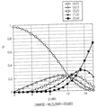
図7〜10には、SNRが20dB、25dBの場合におけるMMSE−MLD、OSD−MLDの閾値ζと(m、n)の検出確率pとの関係を示した。 7 to 10 show the relationship between the threshold ζ of MMSE-MLD and OSD-MLD and the detection probability p of (m, n) when the SNR is 20 dB and 25 dB.
図7、8から明らかなように、MMSE−MLDとOSD−MLDはともに、SNR=20dB、閾値ζ=16dBのとき、(0、4)即ち、すべての送信信号をMLDで検出する確率を約44.7%に低減できることがわかる。同様に、図9、10から明らかなように、SNR=25dB、閾値ζ=18dBのとき、すべての送信信号をMLDで検出する確率を約22.2%に低減できることがわかる。また、SNR=20dB及び25dBのときのMMSE−MLDにおける各(m、n)とOSD−MLDにおける各(m、n)の検出確率を比較すると、(0、4)となる確率は等しいが、OSD−MLDの方がMMSE−MLDよりも(1、3)、(2、2)となる確率は低いことがわかる。これは、OSD−MLDでは、検出した送信信号を干渉成分として受信信号から除去した後、検出した送信信号に対応する通信路を考慮しなくなるため、再び受信SINRを算出する際に干渉成分が低減され、受信SINRが改善されるからである。 As is apparent from FIGS. 7 and 8, both MMSE-MLD and OSD-MLD have (0, 4) when SNR = 20 dB and threshold ζ = 16 dB, ie, the probability that all transmission signals are detected by MLD is approximately It turns out that it can reduce to 44.7%. Similarly, as is apparent from FIGS. 9 and 10, when SNR = 25 dB and threshold value ζ = 18 dB, the probability that all transmission signals are detected by MLD can be reduced to about 22.2%. Further, when the detection probabilities of each (m, n) in MMSE-MLD and each (m, n) in OSD-MLD when SNR = 20 dB and 25 dB are compared, the probability of being (0, 4) is equal. It can be seen that OSD-MLD has a lower probability of (1, 3), (2, 2) than MMSE-MLD. This is because in OSD-MLD, the detected transmission signal is removed from the received signal as an interference component, and then the communication path corresponding to the detected transmission signal is not taken into account, so the interference component is reduced when calculating the received SINR again. This is because the received SINR is improved.
図11〜13には、MMSE−MLD、OSD−MLDの各信号検出法において、SNRが15dB、20dB、25dBの場合における、閾値ζとMLDで必要な乗算数で正規化したときの正規化乗算数との関係をシミュレーションした結果を示した。なお、SNR=15dBの変調方式はQPSK、SNR=20dB、25dBの変調方式は16QAMである。 FIGS. 11 to 13 show normalized multiplications when the signal detection methods of MMSE-MLD and OSD-MLD are normalized with the threshold ζ and the number of multiplications necessary for MLD when the SNR is 15 dB, 20 dB, and 25 dB. The result of simulating the relationship with the number is presented. The modulation scheme with SNR = 15 dB is QPSK, and the modulation scheme with SNR = 20 dB and 25 dB is 16QAM.
図11から明らかなように、SNR=15dBの場合において、閾値ζ=11dBのとき、すなわちMLDとBER特性が同等となる閾値のとき、MLDの乗算数と比較して、MMSE−MLDは約50%、OSD−MLDは約55%の乗算数となることがわかる。なお、OSD−MLDの乗算数は、MMSE−MLDの乗算数よりも多いが、これはSINRを算出する際の乗算数がOSD−MLDの方が多いからである。 As is apparent from FIG. 11, in the case of SNR = 15 dB, when the threshold ζ = 11 dB, that is, the threshold at which the MLD and BER characteristics are equivalent, the MMSE-MLD is about 50 compared with the number of multiplications of the MLD. %, OSD-MLD is a multiplication factor of about 55%. The number of OSD-MLD multiplications is larger than the number of MMSE-MLD multiplications, because the number of multiplications for calculating SINR is larger for OSD-MLD.
同様に、図12から明らかなように、SNR=20dBの場合において、MLDとBER特性が同等となる閾値ζ=16dBのとき、MLDの乗算数と比較して、MMSE−MLDは約46.2%、OSD−MLDは約45.7%の乗算数となることがわかる。 Similarly, as is apparent from FIG. 12, in the case of SNR = 20 dB, MMSE-MLD is about 46.2 when the threshold value ζ = 16 dB at which the MLD and BER characteristics are equivalent compared to the number of multiplications of MLD. %, OSD-MLD is a multiplication factor of about 45.7%.
同様に、図13から明らかなように、SNR=25dBの場合において、MLDとBER特性が同等となる閾値ζ=18dBのとき、MLDの乗算数と比較して、MMSE−MLDでは約22.2%、OSD−MLDでは約21.2%の乗算数となり、演算量を低減できることがわかる。 Similarly, as apparent from FIG. 13, in the case of SNR = 25 dB, when the threshold ζ = 18 dB at which the MLD and BER characteristics are equivalent, the MMSE-MLD has about 22.2 in comparison with the multiplication number of the MLD. %, OSD-MLD has a multiplication factor of about 21.2%, which indicates that the amount of calculation can be reduced.
このように、MMSE−MLD、OSD−MLDは、MLDと同等のBER特性を少ない演算量で得ることができる。 Thus, MMSE-MLD and OSD-MLD can obtain BER characteristics equivalent to MLD with a small amount of computation.
また、変調方式が16QAMの場合のSNR=20dB、25dBのMMSE−MLDとOSD−MLDの乗算数を比較すると、乗算数は、ほぼ等しいことがわかる。これは、表1からわかるように、変調方式が16QAMのときには、各(m、n)において、(0、4)の乗算数が桁違いに多いため、MMSE−MLD、OSD−MLDの乗算数は、(0、4)となる検出確率に大きく依存するが、MMSE−MLDとOSD−MLDは、(0、4)となる検出確率が等しいためであると考えられる。 Further, when the number of multiplications of MMSE-MLD and OSD-MLD of SNR = 20 dB and 25 dB when the modulation method is 16QAM is compared, it can be seen that the number of multiplications is substantially equal. As can be seen from Table 1, when the modulation method is 16QAM, the number of multiplications of (0, 4) is extremely large in each (m, n), so the number of multiplications of MMSE-MLD and OSD-MLD. Depends largely on the detection probability of (0, 4), but it is considered that MMSE-MLD and OSD-MLD have the same detection probability of (0, 4).
また、図5,6から明らかなように、BER特性は、OSD−MLDの方がMMSE−MLDよりも優れているため、乗算数とBERの観点から、OSD−MLDの方がMMSE−MLDよりも優れた信号検出法であることがわかる。 As is clear from FIGS. 5 and 6, the OSD-MLD is superior to the MMSE-MLD in terms of the BER characteristics. Therefore, from the viewpoint of the number of multiplications and the BER, the OSD-MLD is better than the MMSE-MLD. It can be seen that this is an excellent signal detection method.
しかしながら、以下の表2に示すように、変調方式がQPSKのとき、MMSE−MLD、OSD−MLDの演算量は(0、4)以外の検出確率にも大きく依存するため、MMSE−MLDとOSD−MLDの演算量に差が生じる。 However, as shown in Table 2 below, when the modulation method is QPSK, the calculation amount of MMSE-MLD and OSD-MLD greatly depends on detection probabilities other than (0, 4), so MMSE-MLD and OSD -There is a difference in the calculation amount of MLD.
変調方式がQPSKのときも16QAMのときと同様に、SINRの閾値ζが大きくなるに従って、MMSE−MLD、OSD−MLDのBERはMLDのBERに近づくが、MLDと等しいBERとなる閾値では、MMSE−MLDの方がOSD−MLDよりも乗算数が少ないと言える。 When the modulation method is QPSK, the BER of MMSE-MLD and OSD-MLD approaches the BER of MLD as the SINR threshold ζ increases as in the case of 16QAM. It can be said that -MLD has fewer multiplications than OSD-MLD.
従って、変調方式がQPSKのときは、MMSE−MLDの方がOSD−MLDよりも優れていると言える。 Therefore, it can be said that MMSE-MLD is superior to OSD-MLD when the modulation method is QPSK.
10 無線通信システム
12 送信機
14 受信機
16 シンボルマッピング部
18 デマルチプレクサ
20 信号検出部
21 通信路推定部
22 マルチプレクサ
24 シンボルデマッピング部
261〜26Nt 送信アンテナ
281 〜28Nr 受信アンテナ
DESCRIPTION OF SYMBOLS 10 Radio |
Claims (4)
各送信アンテナと各受信アンテナとの間の通信路についての通信路利得を表す通信路推定値を求め、
前記通信路推定値及び雑音の分散に基づいて、各送信アンテナからの送信信号についての信号品質を表すパラメータを各々算出し、
各送信アンテナについての前記パラメータと予め定めた閾値との各々の比較結果に基づいて、前記閾値以上のパラメータに対応する送信アンテナの送信信号については、最小誤差二乗法により送信信号を検出するMMSE検出手段により検出し、前記閾値未満のパラメータに対応する送信アンテナの送信信号については、最尤検出により送信信号を検出する最尤検出手段により検出する
ことを特徴とする通信路推定及びデータ検出方法。 The transmission data transmitted from the plurality of transmission antennas is received by the plurality of reception antennas, and the channel gain between the transmission antenna and the reception antenna is estimated based on the reception data received by each reception antenna, In the channel estimation and data detection method for detecting transmission data,
Find a channel estimate representing the channel gain for the channel between each transmit antenna and each receive antenna,
Based on the channel estimation value and noise variance, each calculates a parameter representing the signal quality for the transmission signal from each transmission antenna,
MMSE detection for detecting a transmission signal by a least error square method for a transmission signal of a transmission antenna corresponding to a parameter equal to or greater than the threshold based on a comparison result between the parameter for each transmission antenna and a predetermined threshold. A transmission path estimation and data detection method characterized in that a transmission signal of a transmission antenna corresponding to a parameter less than the threshold is detected by maximum likelihood detection means for detecting a transmission signal by maximum likelihood detection .
各送信アンテナと各受信アンテナとの間の通信路についての通信路利得を表す通信路推定値を求め、 Find a channel estimate representing the channel gain for the channel between each transmit antenna and each receive antenna,
前記通信路推定値及び雑音の分散に基づいて、各送信アンテナからの送信信号についての信号品質を表すパラメータを各々算出し、 Based on the channel estimation value and noise variance, each calculates a parameter representing the signal quality for the transmission signal from each transmission antenna,
各送信アンテナについての前記パラメータと予め定めた閾値との各々の比較結果に基づいて、前記閾値以上のパラメータに対応する送信アンテナの送信信号については、当該送信信号のうち前記パラメータが最大の送信信号を、最小誤差二乗法により送信信号を検出するMMSE検出手段により検出し、検出した送信信号を干渉成分として受信信号から除去し、当該干渉成分が除去された受信信号に基づいて前記パラメータを再度算出し、算出したパラメータと前記閾値とを比較する処理を、前記閾値以上のパラメータが存在しなくなるまで繰り返し、前記閾値未満のパラメータに対応する送信アンテナの送信信号については、最尤検出により送信信号を検出する最尤検出手段により検出する Based on the comparison results between the parameter for each transmission antenna and a predetermined threshold, for the transmission signal of the transmission antenna corresponding to the parameter equal to or greater than the threshold, the transmission signal having the maximum parameter among the transmission signals Is detected by the MMSE detection means for detecting the transmission signal by the least error square method, the detected transmission signal is removed from the received signal as an interference component, and the parameter is recalculated based on the received signal from which the interference component has been removed. Then, the process of comparing the calculated parameter with the threshold value is repeated until there is no more parameter than the threshold value, and the transmission signal of the transmission antenna corresponding to the parameter less than the threshold value is detected by maximum likelihood detection. Detect by maximum likelihood detection means to detect
ことを特徴とする通信路推定及びデータ検出方法。 A channel estimation and data detection method.
Priority Applications (1)
| Application Number | Priority Date | Filing Date | Title |
|---|---|---|---|
| JP2004181729A JP4381901B2 (en) | 2004-06-18 | 2004-06-18 | Channel estimation and data detection method |
Applications Claiming Priority (1)
| Application Number | Priority Date | Filing Date | Title |
|---|---|---|---|
| JP2004181729A JP4381901B2 (en) | 2004-06-18 | 2004-06-18 | Channel estimation and data detection method |
Publications (2)
| Publication Number | Publication Date |
|---|---|
| JP2006005791A JP2006005791A (en) | 2006-01-05 |
| JP4381901B2 true JP4381901B2 (en) | 2009-12-09 |
Family
ID=35773775
Family Applications (1)
| Application Number | Title | Priority Date | Filing Date |
|---|---|---|---|
| JP2004181729A Active JP4381901B2 (en) | 2004-06-18 | 2004-06-18 | Channel estimation and data detection method |
Country Status (1)
| Country | Link |
|---|---|
| JP (1) | JP4381901B2 (en) |
Families Citing this family (17)
| Publication number | Priority date | Publication date | Assignee | Title |
|---|---|---|---|---|
| US8660210B2 (en) * | 2006-01-23 | 2014-02-25 | Qualcomm Incorporated | Method of packet format dependent selection of MIMO-OFDM demodulator |
| JP4574565B2 (en) * | 2006-02-10 | 2010-11-04 | 日本電信電話株式会社 | Wireless communication system and wireless communication method |
| CN101026428A (en) * | 2006-02-17 | 2007-08-29 | 华为技术有限公司 | Maxium likelihood estimation method and device for multi input multi output system |
| JP4854378B2 (en) * | 2006-05-01 | 2012-01-18 | ソフトバンクBb株式会社 | Wireless transmission system and wireless transmission method |
| JP4813335B2 (en) * | 2006-11-21 | 2011-11-09 | 日本電信電話株式会社 | Wireless signal detection method |
| JP2009060176A (en) * | 2007-08-29 | 2009-03-19 | Kyocera Corp | Radio communication device and radio reception method |
| JP5069579B2 (en) * | 2008-01-30 | 2012-11-07 | 京セラ株式会社 | Wireless communication system, wireless communication apparatus, and wireless communication method |
| US7809075B2 (en) * | 2008-08-18 | 2010-10-05 | Xilinx, Inc. | MIMO symbol detection for SNR higher and lower than a threshold |
| US8558967B2 (en) | 2009-02-12 | 2013-10-15 | Panasonic Corporation | Illuminating lens, lighting device, surface light source, and liquid-crystal display apparatus |
| US8576351B2 (en) | 2009-02-12 | 2013-11-05 | Panasonic Corporation | Illuminating lens, lighting device, surface light source, and liquid-crystal display apparatus |
| US8469554B2 (en) | 2009-02-12 | 2013-06-25 | Panasonic Corporation | Illuminating lens, lighting device, surface light source, and liquid-crystal display apparatus |
| US8508688B2 (en) | 2009-02-12 | 2013-08-13 | Panasonic Corporation | Illuminating lens, lighting device, surface light source, and liquid-crystal display apparatus |
| US8582053B2 (en) | 2009-02-12 | 2013-11-12 | Panasonic Corporation | Illuminating lens, lighting device, surface light source, and liquid-crystal display apparatus |
| JP2010193350A (en) * | 2009-02-20 | 2010-09-02 | Sharp Corp | Communication apparatus and communication system |
| JP5487090B2 (en) | 2010-12-03 | 2014-05-07 | 株式会社日立製作所 | Radio signal processing method and radio communication apparatus |
| EP2775644A4 (en) | 2011-11-02 | 2015-04-08 | Fujitsu Ltd | Wireless communication apparatus and communication method |
| CN107911182B (en) * | 2017-11-21 | 2020-07-14 | 合肥工业大学 | Method for detecting sudden change of environmental characteristic parameters of wireless channel |
-
2004
- 2004-06-18 JP JP2004181729A patent/JP4381901B2/en active Active
Also Published As
| Publication number | Publication date |
|---|---|
| JP2006005791A (en) | 2006-01-05 |
Similar Documents
| Publication | Publication Date | Title |
|---|---|---|
| JP4381901B2 (en) | Channel estimation and data detection method | |
| US11711155B2 (en) | Self-adaptive MIMO detection method and system | |
| EP1897224B1 (en) | Sphere decoding apparatus for mimo channel | |
| EP1802000B1 (en) | Apparatus and method for cancelling interference from neighbor cells in broadband communication system | |
| EP1420529A2 (en) | Receiving apparatus, transmitting apparatus, and reception method in mimo system | |
| US20070155336A1 (en) | Apparatus and method for eliminating multi-user interference | |
| US20050031062A1 (en) | Method and apparatus for determining a shuffling pattern based on a minimum signal to noise ratio in a double space-time transmit diversity system | |
| EP1538772A1 (en) | Apparatus and method for transmitting data using eigenvector selection in MIMO mobile communication systems | |
| US7397874B2 (en) | Method and device for detecting vertical bell laboratories layered space-time codes | |
| TWI479827B (en) | Wireless receiver with receive diversity | |
| KR101106684B1 (en) | Apparatus and method for receiver in multiple antenna system | |
| CN101442388A (en) | Precoding method and apparatus for multi-input multi-output system | |
| US8811215B2 (en) | Apparatus and method for detecting signal in spatial multiplexing system | |
| KR101508700B1 (en) | Apparatus and method for detecting signal in multiple input multiple output wireless communication system | |
| CN101227254A (en) | Method for detecting V-BLAST in MIMO system | |
| JP2008228145A (en) | Receiver in multi-user mimo system, control program and reception control method | |
| WO2012035626A1 (en) | Wireless communication method, wireless communication system, base station, and mobile station | |
| KR101348557B1 (en) | Method for detecting signal using mimo-ofdm system and apparatus thereof | |
| JP5730417B2 (en) | Concepts for providing data detection information | |
| JP5339865B2 (en) | Wireless receiving method and wireless receiving device | |
| Li et al. | Multi-feedback successive interference cancellation with multi-branch processing for MIMO systems | |
| Yang et al. | Fixed-complexity LLL-based signal detection for MIMO systems | |
| Zhou et al. | Fast recursive algorithm for efficient transmit antenna selection in spatial multiplexing systems | |
| KR101289938B1 (en) | Apparatus and method for receiving a signal in a mobile communication system using multiple input multiple output scheme | |
| CN106549898B (en) | MIMO-OFDM system-based SSFE signal detection method and device |
Legal Events
| Date | Code | Title | Description |
|---|---|---|---|
| A621 | Written request for application examination |
Free format text: JAPANESE INTERMEDIATE CODE: A621 Effective date: 20070615 |
|
| A131 | Notification of reasons for refusal |
Free format text: JAPANESE INTERMEDIATE CODE: A131 Effective date: 20090630 |
|
| A521 | Written amendment |
Free format text: JAPANESE INTERMEDIATE CODE: A523 Effective date: 20090820 |
|
| TRDD | Decision of grant or rejection written | ||
| A01 | Written decision to grant a patent or to grant a registration (utility model) |
Free format text: JAPANESE INTERMEDIATE CODE: A01 Effective date: 20090908 |
|
| A01 | Written decision to grant a patent or to grant a registration (utility model) |
Free format text: JAPANESE INTERMEDIATE CODE: A01 |
|
| A61 | First payment of annual fees (during grant procedure) |
Free format text: JAPANESE INTERMEDIATE CODE: A61 Effective date: 20090916 |
|
| FPAY | Renewal fee payment (event date is renewal date of database) |
Free format text: PAYMENT UNTIL: 20121002 Year of fee payment: 3 |
|
| R150 | Certificate of patent or registration of utility model |
Free format text: JAPANESE INTERMEDIATE CODE: R150 |