JP4379569B2 - Image acquisition / display apparatus and method for editing photographing conditions using the apparatus - Google Patents
Image acquisition / display apparatus and method for editing photographing conditions using the apparatus Download PDFInfo
- Publication number
- JP4379569B2 JP4379569B2 JP2003003158A JP2003003158A JP4379569B2 JP 4379569 B2 JP4379569 B2 JP 4379569B2 JP 2003003158 A JP2003003158 A JP 2003003158A JP 2003003158 A JP2003003158 A JP 2003003158A JP 4379569 B2 JP4379569 B2 JP 4379569B2
- Authority
- JP
- Japan
- Prior art keywords
- condition
- editing
- data
- screen
- shooting
- Prior art date
- Legal status (The legal status is an assumption and is not a legal conclusion. Google has not performed a legal analysis and makes no representation as to the accuracy of the status listed.)
- Expired - Fee Related
Links
- 238000000034 method Methods 0.000 title claims description 41
- 238000003384 imaging method Methods 0.000 claims description 133
- 230000005855 radiation Effects 0.000 claims description 39
- 238000006243 chemical reaction Methods 0.000 claims description 36
- 238000000605 extraction Methods 0.000 claims description 27
- 238000012545 processing Methods 0.000 claims description 13
- 239000000284 extract Substances 0.000 claims description 6
- 230000007704 transition Effects 0.000 claims description 3
- 238000010586 diagram Methods 0.000 description 33
- 238000003745 diagnosis Methods 0.000 description 29
- 230000007246 mechanism Effects 0.000 description 19
- 230000006870 function Effects 0.000 description 17
- OAICVXFJPJFONN-UHFFFAOYSA-N Phosphorus Chemical compound [P] OAICVXFJPJFONN-UHFFFAOYSA-N 0.000 description 15
- 230000008707 rearrangement Effects 0.000 description 8
- 230000005284 excitation Effects 0.000 description 7
- 230000008569 process Effects 0.000 description 7
- 210000001015 abdomen Anatomy 0.000 description 5
- 238000012937 correction Methods 0.000 description 5
- 230000000694 effects Effects 0.000 description 5
- 210000003141 lower extremity Anatomy 0.000 description 5
- 230000035945 sensitivity Effects 0.000 description 5
- 230000004936 stimulating effect Effects 0.000 description 5
- 210000001364 upper extremity Anatomy 0.000 description 5
- 238000001514 detection method Methods 0.000 description 3
- 230000001174 ascending effect Effects 0.000 description 2
- 230000008859 change Effects 0.000 description 2
- 201000010099 disease Diseases 0.000 description 2
- 208000037265 diseases, disorders, signs and symptoms Diseases 0.000 description 2
- 238000003780 insertion Methods 0.000 description 2
- 230000037431 insertion Effects 0.000 description 2
- 210000004705 lumbosacral region Anatomy 0.000 description 2
- 210000004072 lung Anatomy 0.000 description 2
- GGCZERPQGJTIQP-UHFFFAOYSA-N sodium;9,10-dioxoanthracene-2-sulfonic acid Chemical compound [Na+].C1=CC=C2C(=O)C3=CC(S(=O)(=O)O)=CC=C3C(=O)C2=C1 GGCZERPQGJTIQP-UHFFFAOYSA-N 0.000 description 2
- 238000003705 background correction Methods 0.000 description 1
- 238000005452 bending Methods 0.000 description 1
- 230000008901 benefit Effects 0.000 description 1
- 230000005540 biological transmission Effects 0.000 description 1
- 238000007796 conventional method Methods 0.000 description 1
- 238000002059 diagnostic imaging Methods 0.000 description 1
- 238000007689 inspection Methods 0.000 description 1
- 230000000873 masking effect Effects 0.000 description 1
- 230000003287 optical effect Effects 0.000 description 1
- 238000002601 radiography Methods 0.000 description 1
- 238000012552 review Methods 0.000 description 1
- 238000005070 sampling Methods 0.000 description 1
- 238000012216 screening Methods 0.000 description 1
- 238000009966 trimming Methods 0.000 description 1
Images


Landscapes
- Studio Devices (AREA)
- Apparatus For Radiation Diagnosis (AREA)
- Television Signal Processing For Recording (AREA)
Description
【0001】
【発明の属する技術分野】
本発明は、データ編集装置及びデータ編集方法に関し、特に、医用画像データの診断に用いられる画像取得表示装置における撮影条件の編集機構及び該画像取得表示装置を用いた撮影条件の編集方法並びに撮影条件配列プログラムに関する。
【0002】
【従来の技術】
X線等の放射線を用いて取得した放射線画像は病気診断用の医用画像として広く用いられており、例えば、被検体を透過したX線を蛍光体層(蛍光スクリーン)に照射し、蛍光体層で発生する可視光を通常の写真と同様に銀塩を使用したフィルムに照射して現像する、いわゆる放射線写真が従来より使用されている。
【0003】
しかし、近年では、銀塩を塗布したフィルムを使用せずに、輝尽性蛍光体やFPD(Flat Panel Detector)等の放射線ディテクタから放射線画像をデジタル信号として直接取り出す放射線画像変換方法が用いられるようになってきている。更に、上記放射線画像変換方法で得られた放射線画像をより診断に適した画像とする目的で各種画像処理が施されるようになってきている。
【0004】
具体的には、例えば、米国特許3,859,527号、特開昭55−12144号公報に、輝尽蛍光体を用い、可視光線又は赤外線を輝尽励起光として使用する放射線画像変換方法が開示されている。この方法は、支持体上に輝尽蛍光体層を形成した放射線画像変換パネルを使用するものであり、この輝尽蛍光体層に被検体を透過した放射線を当てて被検体各部位の放射線透過量に対応する放射線エネルギーを蓄積されて潜像を形成した後、輝尽蛍光体層を所定の波長のレーザ光等の輝尽励起光で走査することにより蓄積された放射線エネルギーを輝尽光として放射させ、この輝尽光をフォトマルチプライヤー等の光電変換素子を用いて光電変換して電気信号として取り出すものである。
【0005】
この輝尽性蛍光体を利用した放射線画像診断システムは、通称コンピューテッドラジオグラフィー(CR)と呼ばれ、大きく分けて、輝尽性蛍光体を読み取り装置に内蔵した立位/臥位専用タイプのシステムと、輝尽性蛍光体を内部に収容した持ち運び可能なカセッテ及びカセッテから蛍光体を引き出し読み取りを行う読み取り装置を組み合わせたカセッテタイプのシステムとに分類される。
【0006】
上記いずれの放射線画像診断システムで放射線画像の撮影を行う場合でも、撮影に際して、体の部位や撮影方向等の多数の撮影条件の中から適切な撮影条件を選択する必要があり、この撮影条件の選択は、通常、患者情報の入力や撮影した画像データの表示を行うコントローラで行われる。
【0007】
コントローラの表示部では、この多数の撮影条件は複数のページに分類され、ページ毎に表示される。そして、「前ページ」ボタンや「後ページ」ボタンによってページを前後に順に送ることにより、選択したい撮影条件を含むページを探し、表示された撮影条件の中から患者の撮影に適した撮影条件を選択する。また、撮影条件が非常に多数である場合は、撮影条件を整理するために撮影条件を階層構造とするものもあり、階層毎に選択肢による選択を行っていくことによって目的とする撮影条件にたどりつくことができる。
【0008】
【特許文献1】
特開昭55−12144号公報
【特許文献2】
米国特許第3,859,527号
【0009】
【発明が解決しようとする課題】
放射線画像診断システムでの撮影条件の選択において、複数のページを順に送って所望の撮影条件を含むページを探し、その中から当該撮影条件を選択する方法では、撮影条件が増えるに従って、後方のページに含まれる撮影条件を選択するときにキー操作を多く必要とし、迅速性に欠けるという問題がある。また、キー操作が多くなればなるほど誤った撮影条件を選択する可能性が増える。
【0010】
また、撮影条件を階層構造とし、階層毎に選択肢の中から選択を行っていくことにより所望の撮影条件を抽出する方法では、撮影条件が多数になるに従って階層も増加し、所望の撮影条件にたどり着くまでのキー操作の数も増える。また、放射線画像診断システムにおける撮影条件には選択頻度に大きな差があり、非常によく選択されるものと殆ど選択されないものとがある。しかし、撮影条件を階層構造にした場合は、撮影条件を選択する際に、選択頻度に関係なく、必ず一定の数だけのキー操作を必要とするため、頻繁に選択される撮影条件であっても殆ど選択されない撮影条件を選択する場合と同様の時間がかかってしまうという問題がある。
【0011】
上記放射線画像診断システムは病院などの医療現場で用いられるものであり、撮影後すぐに診断を行いたいという要望もあり、システム全体に迅速性が要求される。また、放射線画像診断システムを集団検診時において用いることもあり、そのような場合にはさらなる迅速性が要求される。また、放射線は人体に有害なものであるため、撮影の失敗による再撮影は極力避ける必要がある。
【0012】
従って、撮影条件の選択を短時間に行う必要があり、そのためには表示される撮影条件の数を減らすことも考えられるが、必要とする撮影条件が表示されなければ撮影そのものを行うことができなくなってしまう。一方、ユーザーによって必要とする撮影条件はまちまちであり、全ての撮影条件を網羅したマスターデータから抽出、選択して作成した撮影条件群には使用されない撮影条件も多く含まれている。また、表示すべき撮影条件は、継続的な使用に伴って変化するものであり、常に適切な撮影条件を表示するには撮影条件群そのものを編集する必要がある。
【0013】
本発明は、上記問題点に鑑みてなされたものであって、その主たる目的は、撮影条件の選択を迅速かつ確実に行うための撮影条件の編集機構を備えた画像取得表示装置及び該装置を用いた撮影条件の編集方法並びに撮影条件配列プログラムを提供することにある。
【0014】
【問題を解決するための手段】
上記目的を達成するため、本発明の画像取得表示装置は、複数の撮影条件の中から患者の撮影に際して用いられる撮影条件を選択する画面と、前記患者の放射線画像を記録した放射線画像変換媒体から読み取った画像データを表示する画面とが少なくとも表示される画像取得表示装置において、前記複数の撮影条件の各々に、該撮影条件の分類が可能な複数の分類コードを割り当てたシリアルナンバーが付与されており、予め与えられた複数の撮影条件で構成されるマスターデータから前記シリアルナンバーに基づいて抽出され、前記選択画面に表示される複数の撮影条件を編集する手段を備え、前記編集手段では、前記マスターデータからユーザーが必要とする複数の撮影条件を抽出して該ユーザー固有のユーザーデータを作成する第1の編集画面と、作成したユーザーデータの分類を修正、編集する第2の編集画面と、前記ユーザーデータの各々の撮影条件を修正、編集する第3の編集画面とが生成され、各々の編集画面に設けたスイッチにより、前記編集画面間の遷移が行われるものである。
【0018】
また、本発明においては、前記第1の編集画面では、前記マスターデータ又は作成済みのユーザーデータが表示されるコピー元データ表示欄と、作成するユーザーデータが表示されるコピー先データ表示欄とが対比して形成され、各々の表示欄には、前記分類コードの各々を条件とした抽出を行う抽出手段と、前記シリアルナンバー又は前記撮影条件の名称を用いた検索を行う検索手段と、前記シリアルナンバー又は前記撮影条件の撮影部位を用いた並び替えを行う並び替え手段とを含み、前記コピー元データ表示欄から、所定の撮影条件をドラッグ&ドロップで前記コピー先データ表示欄に移動させることにより、前記ユーザーデータが作成される構成とすることができる。
【0019】
また、本発明においては、前記第2の編集画面では、作成するユーザーデータが表示されるデータ表示欄と、モダリティを指定するモダリティ分類欄と、撮影部位を指定する撮影部位分類欄と、指定された前記モダリティ及び前記撮影部位で分類された撮影条件が表示される個別表示欄とが形成され、前記データ表示欄には、前記分類コードの各々を条件とした抽出を行う抽出手段と、前記シリアルナンバー又は前記撮影条件の名称を用いた検索を行う検索手段とを含み、前記データ表示欄から、所定の撮影条件をドラッグ&ドロップで前記個別表示欄に移動させることにより、前記ユーザーデータの分類が修正される構成とすることができ、前記データ表示欄で選択した複数の撮影条件を一括して移動させることにより、該複数の撮影条件がセット条件として前記ユーザーデータに登録されることが好ましい。
【0020】
また、本発明においては、前記第3の編集画面では、画像データの読み取り装置の種別と読み取り条件と読み取り画像とが表示される入力条件欄と、画像データの出力装置の種別と出力条件と画像処理条件と出力画像とが表示される出力条件欄とが形成され、選択された撮影条件の編集が可能となる構成とすることもできる。
【0022】
また、本発明の編集方法は、複数の撮影条件の中から患者の撮影に際して用いられる撮影条件を選択する画面と、前記患者の放射線画像を記録した放射線画像変換媒体から読み取った画像データを表示する画面とが少なくとも表示される画像取得表示装置における撮影条件の編集方法において、前記複数の撮影条件の各々に、複数の分類コードを割り当てたシリアルナンバーを付与し、前記撮影条件を該撮影条件の特質で分類し、予め与えられた複数の撮影条件で構成されるマスターデータから前記シリアルナンバーに基づいて撮影条件を抽出し、抽出した複数の撮影条件を編集する画面を表示し、前記ユーザーによる編集を可能とし、前記撮影条件の編集に際して、前記マスターデータからユーザーが必要とする複数の撮影条件を抽出してユーザーデータを作成する第1の編集画面と、作成したユーザーデータの分類を修正、編集する第2の編集画面と、前記ユーザーデータの各々の撮影条件を修正、編集する第3の編集画面とを生成し、各々の編集画面に設けたスイッチにより、前記編集画面間の遷移を可能とするものである。
【0024】
このように、本発明は、撮影条件に放射線診断の特質を考慮して設定した複数の分類コードで構成されるシリアルナンバーを付与することによって多様な分類を可能とし、また、編集画面として全ての撮影条件を網羅したマスターデータからユーザー固有の撮影条件群を作成する第1の編集画面や、ユーザー固有の撮影条件群の分類を確認、修正する第2の編集画面や、各々の撮影条件を確認、編集する第3の編集画面を用いてドラッグ&ドロップで編集を行うことにより、ユーザー自らが簡単に撮影条件群の編集を行うことができる。また、撮影条件配列プログラムを用いて撮影条件の選択頻度に応じて所定の分類コードの値を設定し、画面の作成にあたって、設定値を参照して表示順を配列し直すことにより、ユーザーは常に使用形態に適合した画面で撮影条件の選択を行うことができる。
【0025】
【発明の実施の形態】
本発明に係る画像取得表示装置は、その好ましい一実施の形態において、放射線画像診断を行う患者の情報を特定する画面と、複数の撮影条件の中から患者の撮影に用いる撮影条件を選択する画面と、患者の放射線画像を記録した放射線画像変換媒体から読み取った画像データを表示する画面とを有し、各々の撮影条件に、放射線診断の特質を考慮して設定した撮影部位、モダリティ、撮影技法、撮影方向、プリントフォーマット等の複数の分類コードを割り当てたシリアルナンバーを付与して該分類コードを用いて多様な分類を可能とし、撮影条件の編集画面として、予めメーカーが設定した複数の撮影条件で構成されるマスターデータからユーザーが任意に抽出したユーザーデータを作成するマスタ編集画面と、作成したユーザーデータの分類を修正、編集する条件キー編集画面と、ユーザーデータの各々の撮影条件を修正、編集する条件編集画面とを設け、ドラッグ&ドロップで撮影条件のコピーやセット条件の設定を行うことにより、ユーザー自らが簡単にユーザーデータを作成することができ、撮影条件選択画面の表示を最適化することにより、選択作業をスムーズに行うことができる。
【0026】
【実施例】
上記した本発明の実施の形態についてさらに詳細に説明すべく、本発明の実施例について図1乃至図11を参照して説明する。図1は、放射線画像診断システムの全体構成を示す図であり、図2は、放射線画像診断システムを構成する画像取得表示装置の構成を示すブロック図である。又、図3乃至図11は、コントローラで表示される画面の構成例を示す図である。
【0027】
なお、以下の説明においては、本発明の特徴である撮影条件の編集機構をカセッテタイプの画像取得表示装置のコントローラに設ける場合について記載するが、カセッテ以外の他の放射線画像変換媒体を使用するシステムや放射線画像変換媒体を使用しない立位/臥位専用タイプのシステム、FPD等の放射線ディテクタを用いて放射線画像をデジタル信号として直接取り出すシステム等の医用画像の表示を行う任意の装置のコントローラに設けることができ、また、これらの医用画像装置にネットワークで接続されて動作する編集装置に上記編集機構を設けることもできる。
【0028】
まず、本発明の特徴である撮影条件の編集機構の理解を容易にするために、放射線画像診断システム及び画像取得表示装置の構成及び放射線画像診断システムを用いた撮影手順について概説する。
【0029】
図1及び図2に示すように、放射線画像診断システム1は、X線撮影を行うX線撮影装置2と撮影したX線画像を読み取って表示する画像取得表示装置6とからなり、X線撮影装置2では、X線管等からなるX線照射装置3から照射されるX線が被検体4を透過してカセッテ5に内蔵された放射線画像変換パネル5a等の放射線画像変換媒体に照射する。この放射線画像変換パネル5aは、輝尽性蛍光体層を有しており、この輝尽性蛍光体にX線が照射されると、そのX線のエネルギーの一部がX線の照射量に応じて輝尽性蛍光体に潜像として蓄積される。
【0030】
そして、X線撮影後、潜像が形成された放射線画像変換パネル5aを内蔵するカセッテ5を画像取得表示装置6の画像読み取り装置(リーダー7)に投入する。リーダー7では、カセッテ5から放射線画像変換パネル5aを取り出し、リーダー7内の励起光照射部7aにより放射線画像変換パネル5aに可視光や赤外光等の励起光が照射されると、放射線画像変換パネル5aは、輝尽性蛍光体が蓄積したX線のエネルギー量に応じて輝尽発光する。この発光光はフィルタ7bを介して光電変換部7cに入力され、光電変換部7cでは当該光信号を発光強度に比例する電圧信号に変換してA/D変換部7dに出力する。このA/D変換部7bは、入力された電圧信号をデジタル画像信号データに変換して、コントローラ8に出力する。
【0031】
コントローラ8は、CRT等の表示部8dやキーボード、タッチパネル等の操作部8eを有しており、このA/D変換部7bから送られたデジタル画像信号データを記憶部8cに記録させるとともに、CRT等の表示部8dに出力したり、DICOMネットワークを介して接続されているレーザーイメージャー9にデータを送信してフィルムとして出力する。
【0032】
また、コントローラ8には、設定した読み取り条件に基づいてリーダー7を制御する制御部8aや、リーダー7で読み取った画像に対して種々の画像処理(補正処理、階調変換処理、トリミング、反転/回転、パラメータ変更、マスキング等)を施す演算処理部8b、受付リスト画面、検索画面、撮影部位選択画面、撮影ルーチン画面等の各種画面を作成する画面作成部8h、カセッテ5のプレートIDを読み取る識別ラベル検出部8fや、本発明の特徴である撮影条件の編集を可能とする撮影条件編集手段8gを備えている。
【0033】
なお、図の構成において、リーダー7とコントローラ8とは分離された形態としているが、これらが一体となって画像取得表示装置6を構成する形態としても良い。また、コントローラ8には、ネットワークを介して遠隔から患者情報を入出力するためのHIS、RIS等の端末10や撮影の履歴情報等を記憶するデータベース11を接続するようにしてもよい。更に、本発明の編集機構を独立した編集装置12に設ける構成としても良い。
【0034】
上記カセッテタイプの放射線画像診断システム1では、カセッテ5と患者情報や撮影条件、読み取り条件等の予約情報との対応関係を明確とするために、予めカセッテ5と予約情報との対応関係を登録した後に撮影を行う方法(前登録)や、放射線撮影前にカセッテ5の登録を行うことなく、カセッテ投入順と予約情報の入力順との対応付けを行う方法(後登録)のいずれかが採用されて、画像データの読み取りが実行される。
【0035】
この前登録と後登録とは各々特徴があり、例えば、リーダー7やコントローラ8が各々異なる場所に多数設置され、多数の放射線技師が撮影を行う病院等では、前登録によって多数の患者の放射線画像診断を的確に行うことができ、一方、リーダー7やコントローラ8の設置台数の少なく、少数の放射線技師が撮影を行う開業医等では、後登録によって迅速かつ効率的にX線撮影を行うことができる。なお、本実施例の特徴である撮影条件の編集機構は、いずれの登録方式を採用する装置においても適用可能である。
【0036】
図3乃至図11の画面構成例を参照して、上記構成の放射線画像診断システム1を用いて患者の撮影し、取得した画像を用いて診断を行う手順について説明し、撮影条件の選択動作の役割及び撮影条件の編集の必要性について述べる。
【0037】
まず、放射線技師等のオペレータは、コントローラ8の表示部8d、操作部8eにより、患者情報の入力を行う。ここでは、図3に示す検索画面13が初期画面として設定されているものとし、入力領域13bのキーボードを操作して所定の検索キーを入力し、検索ボタンをタッチ又はクリックすると、HIS、RIS等の外部情報端末やデータベース等を参照して検索が実行され、患者情報が表示領域13aに表示される。
【0038】
この患者情報は、受付けリスト画面14から入手することもでき、その場合は、検索画面13の[受付リスト]ボタンをタッチして図4に示すような受付けリスト画面14を表示する。この受付リスト画面14には、患者ID、患者氏名、性別、年齢、依頼科、病棟、撮影条件、撮影枚数等の情報が表示領域14aに一覧表示されており、オペレータは一覧表示の中から撮影を行う所定の患者を選択する。そして、[OK]ボタンで検索画面13に戻り、検索画面13に設けた[検査開始]ボタンを選択して検査を開始すると、撮影条件選択画面が表示される。
【0039】
この撮影条件とは、放射線画像を撮影する際に考慮すべき条件であり、選択した撮影条件に基づいて撮影することにより、適正な放射線画像を取得することができる。撮影条件としては、例えば、撮影部位(頭部、胸部、腹部、頚部、腰部、脊椎、肺野、上肢、下肢等)、撮影体位(立位、臥位等)、撮影方向(正面、側面等)、患者の特徴(性別、年齢、体格等)、病名等が挙げられる。
【0040】
この多数の撮影条件は、システムを提供するメーカーが全ての条件を網羅したデータ(メーカーマスターデータ)として提供するが、数百にも及ぶ撮影条件を全て画面に表示するとなると画面が数十ページにもなり、このような多数のページの中から患者に適した撮影条件を迅速に選択することは困難である。そこで、通常、メーカー側で全ての撮影条件の中からユーザーが使用する撮影条件のみを抽出し、かつ、オペレータが容易に選択できるように抽出した撮影条件を分類した画面を作成してユーザーに提供している。
【0041】
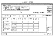
撮影条件を分類した画面として、図5〜8に示すような撮影条件選択画面15が表示される。この撮影条件選択画面15には、例えば、抽出した撮影条件の中で特に使用頻度の高い撮影条件をアイコン15cを用いて見やすく表示する設定条件表示領域15aや、撮影体位、撮影部位等の撮影形態毎に分類された撮影条件を表示する分類表示領域15bとが設けられており、例えば、分類表示領域15bのタグから[お気に入り]を選択すると図5に示すようにユーザーがお気に入りとして登録した撮影条件が表示され、[立位]を選択すると図6に示すように立位として分類された撮影条件が表示され、[臥位]を選択すると図7に示すように臥位として分類された撮影条件が表示され、[カセッテ]を選択すると図8に示すようにカセッテとして分類された撮影条件が各々表示される。そして、オペレータは設定条件表示領域15aから撮影条件を選択したり、立位、臥位、カセッテ等の項目を選択した後、[前ページ]や[次ページ]等のボタンを押して所望の撮影条件が含まれる画面を表示させ、その中から適宜撮影条件を選択する。
【0042】
上記撮影条件選択画面15は、オペレータの操作性を考慮して作成されたものであり、このように整理された画面で撮影条件を選択するのは容易であるが、ユーザーによってメーカーマスターデータから抽出を希望する撮影条件の種類や数は異なり、また、継続的な使用に伴って使用頻度に差が生じたり、新たに使用する撮影条件が生じる等、撮影条件の見直しや画面構成の修正が必要になる場合もある。
【0043】
この場合、従来はメーカーマスターデータから所望の撮影条件を抽出する作業や、撮影条件の表示順を修正する作業等はメーカー側が行っていたが、ユーザーが自ら上記作業を行うことができればメーカーの負担も軽減され、また、ユーザーも必要に応じて適宜使いやすい画面を作成することができる。しかしながら、上述したように、メーカーマスターデータには数百もの撮影条件が含まれ、その中からユーザーが必要とする撮影条件を抽出するのは困難であり、また、編集作業を支援する編集機構を備えた画像取得表示装置や編集装置が存在していなかった。
【0044】
撮影条件の編集が困難となる背景には、各々の撮影条件に付与するシリアルナンバーが順番に採番した通し番号であったり、また、分類可能なコードが付与されている場合でも、コードの構成が放射線診断の特質に合致しておらず、有効な検索や並べ替えができないということにある。そこで、本実施例では、放射線診断の特質を考慮して設定した複数の分類コードで構成されるシリアルナンバーを各々の撮影条件に付与することにより多様な分類を可能とし、かつ、機械操作に不慣れなユーザーであっても検索、抽出を容易に行うことができる編集画面を設けることにより、上記問題を解決している。その具体的な構成については後述する各実施例において説明する。
【0045】
撮影手順の説明に戻ると、撮影条件選択画面15を用いて撮影条件を選択した後、[OK]ボタンを押すと、コントローラ8の識別ラベル検出部8fによりカセッテ5から読み取った識別ラベル情報(プレートID)と撮影条件及び読み取り条件との対応付けが行われる。そして、X線撮影装置2等の放射線画像撮影装置を用いて選択した患者を撮影し、患者のX線透過画像をカセッテ5内部の放射線画像変換パネル5aに潜像として記録する。
【0046】
次に、放射線技師等のオペレータはX線撮影装置2からカセッテ5を取り出し、取り出したカセッテ5をリーダー7の任意のスロットに挿入すると、前登録の場合は、リーダー7はプレートIDを読み取り、プレートIDを検索キーとしてデータベースを検索し、プレートIDに対応する読み取り条件を抽出する。また、後登録の場合は、カセッテ投入順キューと予約選択キューとの対応付けからカセッテ5に対応する読み取り条件を抽出する。その後、リーダー7では設定された読み取り条件に従って、放射線画像変換パネル5aの潜像を読み取る。
【0047】
画像データの読み取り手順としては、まず、読み取り条件として設定された読み取り感度、読み取り解像度に従って、プレート搬送機構の搬送速度やA/D変換部7dのサンプリングピッチが設定される。そして、カセッテ5から放射線画像変換パネル5aが引き出され、走査機構で放射線画像変換パネル5aを走査しながら、放射線画像変換パネル5aに蓄積・保持された画像データを読み出す。
【0048】
そして、放射線画像変換パネル5aに励起光が作用すると、蛍光体内部に蓄積されていたエネルギーが輝尽光として発生し、この輝尽光を集光して光電変換部7cによって電気信号に変換し、この電気信号を対数変換器にて対数変換し(これによって、電気信号は輝尽光の光強度にリニアな電気信号から、輝尽光の光強度の対数リニアな電気信号、すなわち濃度にリニアな電気信号に変換される。)、さらにA/D変換部7dによってデジタル化する。
【0049】
A/D変換部7dから出力される画像データは、演算処理部8bで画像取得表示装置6や放射線画像変換パネル5aに特有の補正処理(シェーディング補正や励起光発生部に起因するムラ補正、放射線画像変換パネルの感度ムラ補正など)、階調変換処理等が施される。
【0050】
その後、図9乃至図11に示すような撮影ルーチン画面が表示される。図9は、代表的な画像データが表示される主表示部16aと、関連して撮影された画像データがサムネイル形式で縮小表示される副表示部16bと、入力した患者情報が表示される患者情報表示領域16cと、モダリティを示すアイコン群(立位アイコン16d、臥位アイコン16e、カセッテアイコン16f)とを備えた一画像形式の撮影ルーチン画面16であり、図10は、複数の画像(図では4つの画像)が対等に大きく表示される表示形式(一括形式)の撮影ルーチン画面17、図11は、2つの画像が対等に大きく表示される表示形式の撮影ルーチン画面18であり、この中から診断に適した表示形式を適宜選択して撮影した画像データを表示して診断を行う。
【0051】
上記一連の動作を繰り返して診断を行うが、医用画像の撮影では緊急を要する場合もあり、また、撮影条件の選択ミスを防止するためにも、撮影条件選択画面にはユーザーの使用形態に応じた必要十分な撮影条件が表示される必要がある。以下に、メーカーマスターデータの中からユーザー自らが撮影条件を抽出して所望の撮影条件選択画面を得るための撮影条件編集機構について説明する。
【0052】
[実施例1]
まず、本発明の第1の実施例に係る撮影条件の編集機構を備えた画像取得表示装置及び該装置を用いた撮影条件の編集方法について、図12乃至図15を参照して説明する。図12乃至図14は、本実施例の撮影条件の編集の際にコントローラに表示される画面構成例を示す図であり、図15は、撮影条件に付与される分類コードの構成を示す図である。
【0053】
前記したように撮影条件は多種多様であり、各々のユーザーの要望に応えるためにメーカーが予め設定するメーカーマスターデータには全ての撮影条件を網羅する必要がある。その結果、撮影条件は多数のページに分割され、多数のページの中から所望の撮影条件を選択しなければならず、撮影条件の選択動作に時間がかかってしまう。撮影条件の選択をスムーズに行うには、不要な撮影条件を削除して撮影条件の数を少なくする方法もあるが、どの撮影条件が必要で、どの撮影条件が不要であるかはユーザー自身が選択するものであり、そのためにはユーザー自身がユーザー固有のマスターデータを作成することが好ましい。
【0054】
そこで、本実施例では、各々の撮影条件に通し番号ではなく、放射線診断の特質を考慮して設定した複数の分類コードにより構成されるシリアルナンバーを付与し、分類コードを用いて抽出や検索、並び替えといった編集作業を容易に行うことができるようにしている。具体的には、図15に示すように、管理フラグ22a、モダリティ22b、部位22d、22e、左右22f、撮影技法22g、撮影方向22h、枝番22i等の複数の分類コード22で構成されるシリアルナンバー23を各々の撮影条件に割り当てて放射線診断に特質に合致した分類ができるようにしている。
【0055】
各々の分類コード22について説明すると、管理フラグ22aはマスターコード自体のバージョンやオリジナル又はコピーの区別をするフラグ等からなり、モダリティ22bは立位、臥位、カセッテ等の読み取り種別を示している。また、部位(1)22c及び部位(2)22dは各々の撮影条件を部位(頭部、胸部、腹部、頚部、腰部、脊椎、肺野、上肢、下肢等)毎に分類するためのコードであり、左右22eは、手、足、顎、左(L)、右(R)等の種別を表している。また、撮影技法22gは、単純/造影/ストレス/前屈/後屈等の撮影の方法を表すコードであり、撮影方向22hは、AP、PA、正面、側面、RAO、LAO、RL、LR等の撮影方向を表すコードである。また、枝番22iはプリントフォーマット(1×1、2×1、1×2等)を表すコードである。
【0056】
すなわち、従来の撮影条件は通し番号で採番されるか、若しくは部位毎に分類して採番されていたため、細かい条件で抽出や検索することができず、また、左右や撮影技法、撮影方向といった撮影条件固有の条件で検索することができず、多量のデータから所望の撮影条件を抽出することは困難であったが、本実施例では、撮影条件固有の分類コードで細かく分類することによって多様な抽出、検索を可能とし、ユーザーの利便性を著しく向上させている。また、上記分類コード以外に予備の領域を設けることによってユーザー固有の条件での分類を行うことができ、また、将来、新たな撮影条件が追加された場合にも対応可能としている。
【0057】
なお、撮影条件の分類コード22としては上記構成に限定されず、少なくとも撮影部位以外に、放射線診断の特質を反映した撮影条件固有の特徴を表す分類コードを1以上含む構成であればよい。
【0058】
上記分類コード22で構成されるシリアルナンバーが付与された撮影条件を用いて、メーカーが提供するマスターデータからユーザーが必要とする撮影条件を抽出したユーザー固有のマスターデータを作成する方法について、図12乃至図14の画面構成例を用いて説明する。
【0059】
図12は、オリジナル又はユーザーが作成したマスターデータから、所望の撮影条件を抽出して新たなユーザーマスターデータを作成するマスター編集画面19の画面構成例であり、図13は、マスター編集画面で作成したユーザーマスターの内容及び分類を確認し、条件キーを編集する条件キー編集画面20の画面構成例であり、図14は、各撮影条件の詳細な内容を表示し、編集する条件編集画面の画面構成例である。
【0060】
本実施例の撮影条件の編集機構は、少なくとも上記3種類の画面から構成されている。まず、マスター編集画面19から説明すると、本画面は、メーカーが提供するオリジナルの撮影条件データ(以下、メーカーマスターデータと称する。)からユーザーが抽出した撮影条件データ(以下、ユーザーマスターデータと称する。)を作成するための画面であり、コピー元のメーカーマスターデータ又は既に作成したユーザーマスターデータを表示するコピー元データ表示欄19aと新たに作成するユーザーマスターデータを表示するコピー先データ表示欄19bとを含み、各々の表示欄は所望の撮影条件を表示可能とするためのスクロール機能や抽出機能(抽出条件入力欄19c)、検索機能(検索ボタン19d)、並び替え機能(並び替えボタン19e)が設けられている。
【0061】
そして、例えば、メーカーマスターデータの中から頭部を条件として抽出を行うと、分類コード22の部位(1)22dが頭部に対応する値のデータが検索され、コピー元データ表示欄19aに表示される。ここで、本実施例の構成では、撮影条件を撮影部位(頭部/頚部/胸部/腹部/脊椎/腰部/上肢/下肢等)のみならず、放射線診断の特質を考慮してモダリティ22bや左右22f、撮影技法22g、撮影方向22h、枝番22i等に細かく分類しているため、抽出条件としてこれらの条件を用いて抽出することができ、例えば、特定のモダリティに用いる撮影条件や特定の撮影技法で撮影する撮影条件、特定の方向から撮影する撮影条件、特定のプリントフォーマットでプリントする撮影条件等、ユーザーのニーズに合致した撮影条件を抽出することができ、撮影条件の選択作業を容易にしている。
【0062】
また、並び替えボタン19eを押すと、全データをシリアルナンバー昇順、シリアルナンバー降順、部位別昇順、部位別降順に並び替えることができ、検索ボタン19dを押すと検索用のウィンドゥが開いてシリアルナンバーや名称で検索することができる。
【0063】
そして、ユーザーは、スクロール機能や抽出機能、検索機能、並び替え機能を用いて所望の撮影条件を表示した後、マウスをクリックしたりカーソルを動かして撮影条件を選択し、ドラッグ&ドロップでデータを移動させると、選択された撮影条件がコピー先データ表示欄19bに表示される。また、簡易選択ボタン19fを押すと、全てのデータを指定したり、特定の部位(頭部/頚部/胸部/腹部/脊椎/腰部/上肢/下肢等)のデータを指定したり、番号の範囲を指定することができ、簡易複写ボタン19gを押すと上記指定のデータを一度にコピーすることもできる。この操作を繰り返して所望の撮影条件の抽出作業を行う。
【0064】
その際、コピーしたデータが多数になるとどの撮影条件をコピーしたかが分かり難くなるため、コピー先データ表示欄19bの抽出条件入力欄19cで所定の条件を選択して抽出したり、並び替えボタン19eで並び替えて選択した撮影条件の確認を行うことができる。そして、編集が終了したらコピーボタンを押すと、ユーザーマスターデータが記憶部8cに記憶される。
【0065】
このように、コピー元データ表示欄19aとコピー先データ表示欄19bとを対比して表示し、各々にスクロール機能や抽出機能、検索機能、並び替え機能を設け、ドラッグ&ドロップで編集可能とすることにより、多数の撮影条件の中から容易に所望の撮影条件を抽出することができ、ユーザー固有のマスターデータの作成が可能となる。
【0066】
また、コピー元データ表示欄19aやコピー先データ表示欄19bに表示された各々の撮影条件の詳細な内容を確認、修正することもできる。その場合は、各々の欄の撮影条件を選択してクリックすると、図14に示すような条件編集画面21が表示される。この条件編集画面21は、例えば、入力条件欄21aと出力条件欄21bとを含み、入力条件欄21aには、画像データを読み取る装置の種別や、感度(低感度/標準/高感度)、画素サイズ(標準/高精細)等の基本条件や、サイズ(六切/四切/大四/大角/半切)や向き(縦/横)、位置(上/中/下/右/左)等の読取画素サイズ、読み取る画像を表示する領域が設けられている。また、出力条件欄21bには、出力先のプリンタの種別や、プリントフォーマット(1画像1コマ/1画像2コマ/2画像2コマ)、出力方法(全体出力/切り出し出力)や各種画像調整、オーバーレイ表示等の設定欄が設けられている。そして、オペレータは条件編集画面21で撮影条件の詳細設定を確認したり、編集してマスター編集画面19に戻って編集作業を続ける。
【0067】
そして、メーカーマスターデータから所望の撮影条件を抽出してユーザーマスターデータを作成して登録すれば、撮影条件選択画面15に登録したユーザーマスターデータの撮影条件が表示される。これにより必要十分な撮影条件のみが表示され、撮影条件の選択作業が容易になるが、メーカーマスターデータに比べて撮影条件の数は少なくなっていてもデータを羅列しただけでは撮影条件の選択に時間がかかる。また、撮影条件の中には単独で使用するものもあれば、複数の撮影条件を組み合わせてセットとして使用するものもある。
【0068】
例えば、通常撮影される画像は、正面+側面、右側面+左側面、右斜位、左斜位など偶数枚数を撮影し比較する場合が多い。特に、胸部正面、胸部側面の場合は2画像をセットとして撮影する場合が多く、腰椎を4方向(正面、側面、右斜位、左斜位)から撮影する場合は、4方向の濃度を同じように調整する必要があり、このような場合には、撮影条件をセット条件として登録しておくことが好ましい。
【0069】
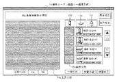
そこで、ユーザーマスターデータを作成した後、図13に示すような条件キー編集画面20を用いて、ユーザーマスターデータをモダリティ毎、撮影部位毎に分類したり、セット条件の設定を行うこともできる。この条件キー編集画面20には、マスター編集画面19のコピー先データ表示欄19bと同様のマスターデータ表示欄20aと、モダリティを選択するモダリティ分類欄20bと、頭部/頚部/胸部/腹部/脊椎/腰部/上肢/下肢等の撮影部位を選択する部位分類欄20cと、選択された分類の撮影条件が表示される条件表示欄20dとが含まれている。
【0070】
そして、マスターデータ表示欄20aに指定したマスターデータを表示させ、抽出条件として各々の分類コード22に対応する条件を選択すると、抽出条件に合致したデータが表示され、モダリティ分類欄20bや部位分類欄20cの中から所望の分類を選択すると、分類コード22を参照して当該分類に対応する撮影条件が条件表示欄20dに表示される。ユーザーは条件表示欄20dに表示される内容を確認し、分類コード22で自動的に割り当てられた分類では不十分な場合には、個別に撮影条件を選択して当該分類から削除したり、新たにマスターデータ表示欄20aからドラッグ&ドロップで所望の撮影条件を移動させて登録したりすることができる。また、マスターデータ表示欄20aで複数の撮影条件を選択して条件表示欄20dに移動させると、この複数の撮影条件がセット条件として当該分類に登録される。
【0071】
なお、条件キー編集画面20においても個別の撮影条件の詳細な内容を確認、編集することができ、その場合は、マスターデータ表示欄20a又は条件表示欄20dの各々の撮影条件をクリックすると、前記した条件編集画面21が表示されて詳細な内容の確認及び編集が可能となる。
【0072】
上記構成のマスター編集画面19、条件キー編集画面20、条件編集画面21を用いてメーカーマスターデータ又は既に作成したユーザーマスターデータから新たなユーザーマスターデータを作成し、更にその分類を修正したり、セット条件を登録すると、撮影条件選択画面15にはその内容を反映して分類された撮影条件が分類表示欄15bに表示され、ユーザーの利便性を向上させることができる。
【0073】
このように、本実施例の撮影条件の編集機構及び撮影条件の編集方法では、撮影条件に、放射線診断の特質を考慮して設定した複数の分類コードで構成されるシリアルナンバーを付与することにより、従来に比べてより高度で多彩な抽出や検索を行うことができる。また、図12乃至図14に示すような編集画面を用いることにより、機械操作に不慣れなユーザーであっても多数の撮影条件の中から所望の撮影条件を抽出したり、分類を修正したり、複数の撮影条件をセット条件として登録することができる。
【0074】
[実施例2]
次に、本発明の第2の実施例に係る撮影条件の編集機構を備えた画像取得表示装置及び該装置を用いた撮影条件の編集方法並びに撮影条件配列プログラムについて、図16及び図17を参照して説明する。図16は、本実施例の撮影条件の編集機構を備えたコントローラの構成を示す図であり、図17は、撮影条件に付与される分類コードの構成を示す図である。なお、本実施例は、撮影条件編集手段に学習機能を設けて撮影条件の表示順を自動的に再配列させることを特徴とするものであり、他の部分の構成、動作に関しては前記した第1の実施例と同様である。
【0075】
すなわち、前記した第1の実施例では、ユーザー自らがマスター編集画面19や条件キー編集画面20、条件編集画面21等を用いてユーザーマスターデータを作成したが、撮影を重ねるに従って、ユーザーマスターデータの中でも頻繁に使用される撮影条件やほとんど使用されない撮影条件が生じる。その場合、ユーザーは各種編集画面を用いて不要な撮影条件を削除して撮影条件選択画面15を取り扱いやすくすることができるが、撮影条件の選択頻度を参照して撮影条件の構成や表示順をコントローラ8で自動的に調整させることもできる。
【0076】
例えば、図16に示すように、コントローラ8に、制御部8a、演算処理部8b、記憶部8c、表示部8d、操作部8e、識別ラベル検出部8f、撮影条件編集手段8g、画面作成部8hに加えて、撮影条件の選択頻度を参照してユーザーマスターデータの並び替えを行うデータ配列手段8iを設け、撮影条件選択画面15を作成する際に、選択頻度に応じて撮影条件の表示順を適宜更新することができる。
【0077】
このような並び替えを実現するには、例えば、図17に示すように、撮影条件に付与される分類コード22の予備欄に各々の撮影条件の選択頻度に応じた数値を書き込む頻度領域22jを設け、撮影条件選択画面15において撮影条件が選択されたら、記憶部8cでは選択頻度を順次加算して記憶し、演算処理部8bでは、選択頻度又は選択頻度に対応付けて設定される値を頻度領域22jに書き込むことによって、各々の撮影条件を選択頻度で識別することができる。そして、選択頻度に応じて頻繁に選択される撮影条件を前に、ほとんど選択されない撮影条件を後ろに表示することにより、ユーザーが撮影条件を選択するための時間を短縮することができる。
【0078】
また、選択頻度に代えて撮影条件が選択された日付を分類コード22の所定の領域に記憶し、日付の新しい順に撮影条件を表示することもできる。また、緊急に撮影する場合が多い部位を前に表示したり、複数の医師や放射線技師、依頼科にまたがる部位を前に表示することもでき、この場合も分類コード22の所定の領域にメーカー又はユーザーが数値を設定し、撮影条件選択画面15の作成に際してその数値を参照して表示順を設定すればよい。
【0079】
このような表示順の再配列を自動的に行うこともできる。その場合には、撮影条件のシリアルナンバー23から所定の分類コード22の値を抽出する処理と、撮影条件選択画面15での撮影条件の選択に応じて、当該撮影条件の分類コードの値を加算する処理と、複数の撮影条件を分類コードの値を参照して順位付けする処理と、該順位に基づいて表示位置を設定する処理とを行う撮影条件配列プログラムをコントローラ8にロードし、実行させることにより可能である。
【0080】
このように、複数の分類コードで構成されるシリアルナンバーの特徴を生かして、選択頻度や撮影の日付等を記録して分類コードに書き込み、分類コードの値を考慮して撮影条件の表示順を自動的に更新することによって、常に取り扱いやすい画面を表示することができ、ユーザーの撮影条件の選択に要する時間を短縮して医用診断をスムーズに行うことができる。
【0081】
なお、上記各実施例では、撮影条件の編集について記載したが、本発明は上記各実施例に限定されるものではなく、任意のデータ列からユーザーの使用形態に適したデータを抽出して新たなデータ列を生成する編集機構、編集方法、編集装置に適用することができる。
【0082】
【発明の効果】
以上説明したように、本発明の撮影条件編集機構を備えた画像取得表示装置及び該装置を用いた撮影条件編集方法並びに撮影条件配列プログラムによれば、下記記載の効果を奏する。
【0083】
本発明の第1の効果は、簡便かつ確実に、ユーザー自らがユーザーマスターデータの編集を行うことができるということである。
【0084】
その理由は、撮影条件に、放射線診断の特質を考慮して設定した複数の分類コードで構成されるシリアルナンバーを付与することにより、撮影部位のみならず、撮影技法や撮影方向等を用いて抽出や検索を行うことができるからである。また、編集画面としてメーカーマスターデータからユーザーマスターデータを作成するマスター編集画面や、ユーザーマスターデータの分類を確認、編集する条件キー編集画面や各々の撮影条件を確認、編集する条件編集画面を用い、抽出機能や検索機能、並び替え機能により所望の撮影条件を表示させ、ドラッグ&ドロップで編集することができるからである。
【0085】
また、本発明の第2の効果は、選択頻度に応じて撮影条件の表示順を自動的に更新することができるということである。
【0086】
その理由は、編集機構を備えるコントローラに、撮影条件配列プログラムをロードすることにより、各々の撮影条件の所定の分類コードの値を抽出する処理と、撮影条件の選択に際して該撮影条件の分類コードの値を書き換える処理と、分類コードの値に基づいて表示順を設定する処理と、表示順に基づいて表示位置を設定する処理とを実行させることができるからである。
【0087】
そして上記効果により、ユーザーは常に取り扱いやすい画面で撮影条件の選択を行うことができ、医用診断をスムーズに行うことができる。
【図面の簡単な説明】
【図1】本発明に係る放射線画像診断システムの全体構成を示す図である。
【図2】本発明に係る放射線画像診断システムを構成する画像取得表示装置の構成を示すブロック図である。
【図3】本発明に係る画像取得表示装置のコントローラに表示される画面の構成例を示す図であり、患者情報の検索画面を示す図である。
【図4】本発明に係る画像取得表示装置のコントローラに表示される画面の構成例を示す図であり、患者情報の受付けリスト画面を示す図である。
【図5】本発明に係る画像取得表示装置のコントローラに表示される画面の構成例を示す図であり、撮影条件の選択画面(お気に入り)を示す図である。
【図6】本発明に係る画像取得表示装置のコントローラに表示される画面の構成例を示す図であり、撮影条件の選択画面(立位)を示す図である。
【図7】本発明に係る画像取得表示装置のコントローラに表示される画面の構成例を示す図であり、撮影条件の選択画面(臥位)を示す図である。
【図8】本発明に係る画像取得表示装置のコントローラに表示される画面の構成例を示す図であり、撮影条件の選択画面(カセッテ)を示す図である。
【図9】本発明に係る画像取得表示装置のコントローラに表示される画面の構成例を示す図であり、画像データの表示画面(一画像形式)を示す図である。
【図10】本発明に係る画像取得表示装置のコントローラに表示される画面の構成例を示す図であり、画像データの表示画面(一括形式)を示す図である。
【図11】本発明に係る画像取得表示装置のコントローラに表示される画面の構成例を示す図であり、画像データの表示画面(一括形式)を示す図である。
【図12】本発明の第1の実施例に係る画像取得表示装置のコントローラに表示される撮影条件編集画面(マスター編集画面)の構成例を示す図である。
【図13】本発明の第1の実施例に係る画像取得表示装置のコントローラに表示される撮影条件編集画面(条件キー編集画面)の構成例を示す図である。
【図14】本発明の第1の実施例に係る画像取得表示装置のコントローラに表示される撮影条件編集画面(条件編集画面面)の構成例を示す図である。
【図15】本発明の第1の実施例に係る撮影条件に付与する分類コードの構成を示す図である。
【図16】本発明の第2の実施例に係る放射線画像診断システムを構成するコントローラの構成を示すブロック図である。
【図17】本発明の第2の実施例に係る撮影条件に付与する分類コードの構成を示す図である。
【符号の説明】
1 放射線画像診断システム
2 X線撮影装置
3 X線照射装置
4 被検体
5 カセッテ
5 放射線画像変換パネル
6 画像取得表示装置
7 リーダー
7a 励起光照射部
7b フィルタ
7c 光電変換部
7d A/D変換部
8 コントローラ
8a 制御部
8b 演算処理部
8c 記憶部
8d 表示部
8e 操作部
8f 識別ラベル検出部
8g 撮影条件編集手段
8h 画面作成部
8i データ配列手段
9 イメージャー
10 HIS、RIS
11 データベース
12 編集装置
13 検索画面
13a 表示領域
13b 入力領域
14 受付けリスト画面
14a 表示領域
15 撮影条件選択画面
15a 設定条件表示領域
15b 分類表示領域
15c アイコン
16 撮影ルーチン画面(一画像形式)
16a 主表示部
16b 副表示部
16c 患者情報表示領域
16d 立位アイコン
16e 臥位アイコン
16f カセッテアイコン
17 撮影ルーチン画面(一括形式(4画像))
17a 画像表示部
18 撮影ルーチン画面(一括形式(2画像))
18a 画像表示部
19 マスター編集画面
19a コピー元データ表示欄
19b コピー先データ表示欄
19c 抽出条件入力欄
19d 検索ボタン
19e 並び替えボタン
19f 簡易選択ボタン
19g 簡易複写ボタン
20 条件キー編集画面
20a マスターデータ表示欄
20b モダリティ分類欄
20c 部位分類欄
20d 条件表示欄
21 条件編集画面
21a 入力条件欄
21b 出力条件欄
22 分類コード
22a 管理フラグ領域
22b モダリティ領域
22c 予備領域
22d 部位(1)領域
22e 部位(2)領域
22f 左右領域
22g 撮影技法領域
22h 撮影方向領域
22i 枝番領域
22j 頻度領域
23 シリアルナンバー[0001]
BACKGROUND OF THE INVENTION
The present invention relates to a data editing apparatus and a data editing method, and more particularly, to an imaging condition editing mechanism in an image acquisition / display apparatus used for diagnosis of medical image data, an imaging condition editing method using the image acquisition / display apparatus, and an imaging condition. It relates to an array program.
[0002]
[Prior art]
Radiation images acquired using radiation such as X-rays are widely used as medical images for diagnosing diseases. For example, a phosphor layer (phosphor screen) is irradiated with X-rays transmitted through a subject, and the phosphor layer In the past, so-called radiographs have been used, in which visible light generated in
[0003]
However, in recent years, a radiation image conversion method for directly extracting a radiation image as a digital signal from a radiation detector such as a stimulable phosphor or FPD (Flat Panel Detector) without using a film coated with silver salt has been used. It is becoming. Furthermore, various image processes have been performed for the purpose of making the radiographic image obtained by the radiographic image conversion method more suitable for diagnosis.
[0004]
Specifically, for example, in US Pat. No. 3,859,527 and JP-A-55-12144, there is a radiation image conversion method using a stimulable phosphor and using visible light or infrared light as stimulated excitation light. It is disclosed. This method uses a radiation image conversion panel in which a photostimulable phosphor layer is formed on a support, and the radiation transmitted through the subject is applied to the photostimulable phosphor layer to transmit the radiation through each part of the subject. After the radiation energy corresponding to the amount is accumulated to form a latent image, the accumulated radiation energy is used as the stimulating light by scanning the stimulable phosphor layer with stimulating excitation light such as laser light of a predetermined wavelength. The light is emitted, and the stimulated light is photoelectrically converted using a photoelectric conversion element such as a photomultiplier to be taken out as an electric signal.
[0005]
Radiation imaging diagnostic systems using stimulable phosphors are commonly referred to as computed radiography (CR), and can be broadly divided into standing / recumbent position types that contain stimulable phosphors in readers. And a cassette type system in which a portable cassette containing a stimulable phosphor and a reading device for extracting and reading the phosphor from the cassette are combined.
[0006]
Even when radiographic imaging is performed with any of the above radiographic diagnostic systems, it is necessary to select an appropriate imaging condition from a number of imaging conditions such as a body part and an imaging direction. The selection is usually performed by a controller that inputs patient information and displays captured image data.
[0007]
In the display unit of the controller, the large number of shooting conditions are classified into a plurality of pages and displayed for each page. Then, by using the “Previous Page” and “Next Page” buttons, the pages are moved forward and backward to find a page that includes the imaging conditions that you want to select, and the imaging conditions that are appropriate for the patient's imaging are displayed from the displayed imaging conditions. select. In addition, when there are a large number of shooting conditions, some shooting conditions have a hierarchical structure in order to organize the shooting conditions, and the target shooting conditions can be reached by selecting options for each layer. be able to.
[0008]
[Patent Document 1]
Japanese Patent Laid-Open No. 55-12144
[Patent Document 2]
U.S. Pat. No. 3,859,527
[0009]
[Problems to be solved by the invention]
In the selection of imaging conditions in the radiological image diagnosis system, in a method in which a plurality of pages are sequentially sent to search for a page including a desired imaging condition, and the imaging condition is selected from among the pages, as the imaging conditions increase, the pages on the back There is a problem in that a large number of key operations are required when selecting the shooting conditions included in the, and lack of quickness. In addition, as the number of key operations increases, the possibility of selecting an erroneous shooting condition increases.
[0010]
Also, in the method of extracting desired shooting conditions by making the shooting conditions into a hierarchical structure and selecting from the choices for each layer, the hierarchy increases as the number of shooting conditions increases, and the desired shooting conditions are achieved. The number of key operations to reach will also increase. In addition, there is a large difference in the selection frequency in the imaging conditions in the radiological image diagnostic system, and there are some that are selected very well and those that are hardly selected. However, when shooting conditions have a hierarchical structure, a certain number of key operations are always required when selecting shooting conditions, regardless of the frequency of selection. However, there is a problem that it takes the same time as selecting an imaging condition that is hardly selected.
[0011]
The radiological image diagnosis system is used in a medical field such as a hospital, and there is also a demand to make a diagnosis immediately after imaging, and the entire system is required to be quick. In addition, the radiological image diagnostic system may be used at the time of mass screening, and in such a case, further rapidity is required. In addition, since radiation is harmful to the human body, it is necessary to avoid re-imaging due to imaging failure as much as possible.
[0012]
Therefore, it is necessary to select the shooting conditions in a short time. To that end, it may be possible to reduce the number of shooting conditions displayed. However, if the required shooting conditions are not displayed, shooting itself can be performed. It will disappear. On the other hand, the shooting conditions required by the user vary, and many shooting conditions that are not used are included in the shooting condition group extracted and selected from the master data covering all shooting conditions. Further, the shooting conditions to be displayed change with continuous use, and it is necessary to edit the shooting condition group itself in order to always display appropriate shooting conditions.
[0013]
The present invention has been made in view of the above problems, and a main object of the present invention is to provide an image acquisition / display apparatus including an imaging condition editing mechanism for quickly and reliably selecting an imaging condition, and the apparatus. It is an object of the present invention to provide a method for editing used shooting conditions and a shooting condition array program.
[0014]
[Means for solving problems]
In order to achieve the above object, an image acquisition and display apparatus according to the present invention includes a screen for selecting an imaging condition used for imaging a patient from a plurality of imaging conditions, and a radiographic image conversion medium on which the radiographic image of the patient is recorded. In the image acquisition and display device in which at least a screen for displaying the read image data is displayed, each of the plurality of shooting conditions is assigned a serial number to which a plurality of classification codes capable of classifying the shooting conditions are assigned. And means for editing a plurality of shooting conditions that are extracted based on the serial number from master data composed of a plurality of shooting conditions given in advance and displayed on the selection screen. The editing means extracts a plurality of shooting conditions required by the user from the master data and creates user data unique to the user, and corrects and edits the classification of the created user data. A second editing screen and a third editing screen for correcting and editing each shooting condition of the user data are generated, and a transition between the editing screens is performed by a switch provided on each editing screen. Is.
[0018]
In the present invention, the first editing screen includes a copy source data display field in which the master data or created user data is displayed, and a copy destination data display field in which user data to be created is displayed. Each display column is formed in contrast, an extraction means for performing extraction using each of the classification codes as a condition, a search means for performing a search using the serial number or the name of the photographing condition, and the serial number Rearrangement means for performing rearrangement using the number or the imaging part of the imaging condition, and by dragging and dropping the predetermined imaging condition from the copy source data display field to the copy destination data display field The user data can be created.
[0019]
In the present invention, the second edit screen is designated with a data display field for displaying user data to be created, a modality classification field for designating a modality, and an imaging part classification field for designating an imaging part. In addition, an individual display field for displaying the imaging conditions classified by the modality and the imaging region is formed, and the data display field includes an extraction means for performing extraction based on each of the classification codes, and the serial Search means for performing a search using a number or the name of the shooting condition, and by moving a predetermined shooting condition from the data display column to the individual display column by drag and drop, the user data can be classified. The plurality of shooting conditions can be corrected, and the plurality of shooting conditions selected in the data display field can be moved collectively. It is preferable to be registered in the user data as a set condition.
[0020]
In the present invention, on the third editing screen, an input condition column for displaying a type of image data reading device, a reading condition, and a read image, a type of image data output device, an output condition, and an image An output condition field in which processing conditions and output images are displayed is formed, and the selected photographing condition can be edited.
[0022]
The editing method of the present invention displays a screen for selecting an imaging condition used for imaging a patient from a plurality of imaging conditions, and image data read from a radiographic image conversion medium on which the radiographic image of the patient is recorded. In the method for editing shooting conditions in an image acquisition and display device in which at least a screen is displayed, a serial number assigned with a plurality of classification codes is assigned to each of the plurality of shooting conditions, and the shooting conditions are characteristics of the shooting conditions. The shooting conditions are extracted based on the serial number from the master data composed of a plurality of shooting conditions given in advance, and a screen for editing the extracted shooting conditions is displayed. Possible When editing the shooting conditions, a first editing screen for creating user data by extracting a plurality of shooting conditions required by the user from the master data, and a first editing screen for correcting and editing the classification of the created
[0024]
As described above, the present invention enables various classifications by assigning serial numbers composed of a plurality of classification codes set in consideration of the characteristics of radiological diagnosis to the imaging conditions. First editing screen for creating user-specific shooting condition groups from master data covering shooting conditions, second editing screen for checking and correcting user-specific shooting condition groups, and checking each shooting condition The user can easily edit the photographing condition group by performing drag and drop editing using the third editing screen to be edited. In addition, by setting the value of a predetermined classification code according to the selection frequency of shooting conditions using the shooting condition array program, and by rearranging the display order with reference to the set values when creating the screen, the user can always Shooting conditions can be selected on a screen suitable for the usage pattern.
[0025]
DETAILED DESCRIPTION OF THE INVENTION
In a preferred embodiment of the image acquisition and display apparatus according to the present invention, a screen for specifying information of a patient who performs radiological image diagnosis, and a screen for selecting an imaging condition used for imaging the patient from a plurality of imaging conditions. And a screen for displaying image data read from a radiographic image conversion medium on which a radiographic image of a patient is recorded, and an imaging region, modality, and imaging technique set in consideration of the characteristics of radiation diagnosis for each imaging condition A serial number to which a plurality of classification codes such as shooting direction and print format are assigned is assigned to enable various classifications using the classification codes, and a plurality of shooting conditions set in advance by the manufacturer as a shooting condition editing screen. Master edit screen to create user data arbitrarily extracted by the user from the master data composed of By providing a condition key editing screen for correcting and editing classifications, and a condition editing screen for correcting and editing each shooting condition of user data, and copying and setting shooting conditions by drag and drop, the user can The user can easily create user data, and the selection operation can be performed smoothly by optimizing the display of the photographing condition selection screen.
[0026]
【Example】
In order to describe the above-described embodiment of the present invention in more detail, an example of the present invention will be described with reference to FIGS. FIG. 1 is a diagram showing an overall configuration of a radiological image diagnostic system, and FIG. 2 is a block diagram showing a configuration of an image acquisition and display device that constitutes the radiographic image diagnostic system. FIGS. 3 to 11 are diagrams showing examples of screens displayed on the controller.
[0027]
In the following description, a case where an imaging condition editing mechanism, which is a feature of the present invention, is provided in a controller of a cassette type image acquisition / display apparatus will be described. However, a system using a radiation image conversion medium other than a cassette Or a system dedicated to a standing or lying position that does not use a radiographic image conversion medium, or a system of any device that displays a medical image such as a system that directly extracts a radiographic image as a digital signal using a radiation detector such as an FPD It is also possible to provide the editing mechanism in an editing apparatus that operates by being connected to these medical image apparatuses via a network.
[0028]
First, in order to facilitate understanding of the imaging condition editing mechanism, which is a feature of the present invention, the configuration of the radiation image diagnostic system and the image acquisition / display apparatus and the imaging procedure using the radiation image diagnostic system will be outlined.
[0029]
As shown in FIGS. 1 and 2, the radiological
[0030]
Then, after X-ray imaging, the
[0031]
The
[0032]
The
[0033]
In the configuration shown in the figure, the
[0034]
In the above-mentioned cassette type radiographic
[0035]
The pre-registration and the post-registration have their respective characteristics. For example, in a hospital where a large number of
[0036]
With reference to the screen configuration examples of FIGS. 3 to 11, a procedure for imaging a patient using the radiological
[0037]
First, an operator such as a radiologist inputs patient information through the
[0038]
This patient information can also be obtained from the
[0039]
This imaging condition is a condition that should be taken into account when capturing a radiographic image, and an appropriate radiographic image can be acquired by imaging based on the selected imaging condition. The imaging conditions include, for example, an imaging region (head, chest, abdomen, neck, waist, spine, lung field, upper limb, lower limb, etc.), an imaging position (standing position, supine position, etc.), an imaging direction (front, side, etc.) ), Patient characteristics (sex, age, physique, etc.), disease name, etc.
[0040]
These many shooting conditions are provided as data covering all the conditions (maker master data) by the manufacturer that provides the system. However, if all of the shooting conditions of several hundreds are displayed on the screen, the screen will be several dozen pages. In addition, it is difficult to quickly select imaging conditions suitable for the patient from such a large number of pages. Therefore, the manufacturer usually extracts only the shooting conditions used by the user from all the shooting conditions, and creates and provides the user with a screen that classifies the extracted shooting conditions so that the operator can easily select them. is doing.
[0041]
A shooting
[0042]
The shooting
[0043]
In this case, in the past, the manufacturer has performed the task of extracting the desired shooting conditions from the manufacturer master data and the operation of correcting the display order of the shooting conditions. In addition, the user can create a user-friendly screen as needed. However, as described above, the manufacturer master data includes hundreds of shooting conditions, and it is difficult to extract the shooting conditions required by the user, and an editing mechanism that supports editing work is provided. There was no image acquisition / display device or editing device provided.
[0044]
The background that makes it difficult to edit shooting conditions is the serial number assigned to each shooting condition in sequence, or even if a code that can be classified is assigned, the code configuration is It does not match the characteristics of radiological diagnosis and cannot be effectively searched or sorted. In this embodiment, therefore, various classifications can be made by assigning serial numbers composed of a plurality of classification codes set in consideration of the characteristics of radiological diagnosis to each imaging condition, and unfamiliar with machine operation. The above problem is solved by providing an editing screen that enables even a simple user to search and extract. The specific configuration will be described in each embodiment described later.
[0045]
Returning to the description of the shooting procedure, after selecting the shooting condition using the shooting
[0046]
Next, an operator such as a radiologist takes out the
[0047]
As a procedure for reading image data, first, according to the reading sensitivity and reading resolution set as reading conditions, the conveying speed of the plate conveying mechanism and the sampling pitch of the A / D converter 7d are set. Then, the radiation image conversion panel 5a is pulled out from the
[0048]
When excitation light acts on the radiation image conversion panel 5a, the energy accumulated in the phosphor is generated as stimulating light, and the stimulated light is collected and converted into an electrical signal by the photoelectric conversion unit 7c. The logarithmic converter converts the electric signal into a logarithmic converter (the electric signal is changed from an electric signal linear to the light intensity of the stimulating light to a logarithmic linear electric signal of the light intensity of the stimulating light, that is, linear to the concentration. The digital signal is further converted into a digital signal by the A / D converter 7d.
[0049]
The image data output from the A / D conversion unit 7d is subjected to correction processing (shading correction, unevenness correction caused by the excitation light generation unit, radiation correction) specific to the image acquisition display device 6 and the radiation image conversion panel 5a by the
[0050]
Thereafter, a photographing routine screen as shown in FIGS. 9 to 11 is displayed. FIG. 9 shows a main display unit 16a on which representative image data is displayed, a sub-display unit 16b on which related captured image data is reduced and displayed in a thumbnail format, and a patient on which input patient information is displayed. FIG. 10 shows a
[0051]
Diagnosis is performed by repeating the above series of operations. However, medical imaging may be urgent, and in order to prevent mistakes in selecting imaging conditions, the imaging condition selection screen will be displayed according to the user's usage. Necessary and sufficient shooting conditions must be displayed. A shooting condition editing mechanism for allowing the user himself to extract shooting conditions from the maker master data and obtaining a desired shooting condition selection screen will be described below.
[0052]
[Example 1]
First, an image acquisition / display apparatus having an imaging condition editing mechanism according to a first embodiment of the present invention and an imaging condition editing method using the apparatus will be described with reference to FIGS. FIGS. 12 to 14 are diagrams showing examples of screen configurations displayed on the controller when shooting conditions are edited according to the present embodiment, and FIG. 15 is a diagram showing a configuration of classification codes assigned to shooting conditions. is there.
[0053]
As described above, there are a wide variety of shooting conditions, and it is necessary to cover all shooting conditions in the manufacturer master data set in advance by the manufacturer in order to meet the demands of each user. As a result, the shooting condition is divided into a large number of pages, and a desired shooting condition must be selected from the large number of pages, and the shooting condition selection operation takes time. To select shooting conditions smoothly, you can delete unnecessary shooting conditions and reduce the number of shooting conditions. However, it is up to you to decide which shooting conditions are required and which shooting conditions are unnecessary. For this purpose, it is preferable that the user himself creates user-specific master data.
[0054]
Therefore, in this embodiment, serial numbers composed of a plurality of classification codes set in consideration of the characteristics of radiological diagnosis are assigned to each imaging condition instead of serial numbers, and extraction, search, and arrangement using the classification codes are performed. Editing work such as replacement can be performed easily. More specifically, as shown in FIG. 15, a serial composed of a plurality of
[0055]
Each of the
[0056]
That is, the conventional imaging conditions are numbered by serial numbers or classified and numbered for each part, so that extraction and search cannot be performed with detailed conditions, and the right and left, imaging technique, imaging direction, etc. Although it was difficult to retrieve the desired shooting conditions from a large amount of data because it was not possible to search with conditions specific to the shooting conditions, in this embodiment, various classifications can be made by finely classifying with the classification codes specific to the shooting conditions. Extraction and search are possible, and the convenience of the user is remarkably improved. Further, by providing a spare area in addition to the above classification code, it is possible to perform classification based on user-specific conditions, and it is possible to cope with new imaging conditions added in the future.
[0057]
The imaging
[0058]
FIG. 12 shows a method for creating user-specific master data in which shooting conditions required by a user are extracted from master data provided by a manufacturer using shooting conditions to which a serial number composed of the
[0059]
FIG. 12 is a screen configuration example of a master editing screen 19 that creates new user master data by extracting desired shooting conditions from original or user-created master data, and FIG. 13 is created on the master editing screen. FIG. 14 is a screen configuration example of the condition key editing screen 20 for confirming the contents and classification of the user master and editing the condition key. FIG. 14 shows a screen of the condition editing screen for displaying and editing the detailed contents of each photographing condition. It is a structural example.
[0060]
The photographing condition editing mechanism of this embodiment is composed of at least the above three types of screens. First, the master editing screen 19 will be described. This screen is referred to as shooting condition data (hereinafter referred to as user master data) extracted by the user from original shooting condition data provided by the manufacturer (hereinafter referred to as manufacturer master data). ), A copy source data display column 19a for displaying copy source maker master data or already created user master data, and a copy destination data display column 19b for displaying newly created user master data Each display field has a scroll function, an extraction function (extraction condition input field 19c), a search function (search button 19d), and a rearrangement function (rearrangement button 19e) for enabling display of desired shooting conditions. Is provided.
[0061]
For example, when extraction is performed from the maker master data on the condition of the head, the data of the value corresponding to the head (1) 22d of the
[0062]
When the sort button 19e is pressed, all data can be sorted in ascending order of serial number, serial number descending order, ascending order by part, and descending order by part. When the search button 19d is pressed, a search window is opened and the serial number is opened. You can search by name.
[0063]
The user displays the desired shooting conditions using the scroll function, extraction function, search function, and sort function, then clicks the mouse or moves the cursor to select the shooting conditions, and drag and drop the data. When moved, the selected shooting condition is displayed in the copy destination data display field 19b. When the simple selection button 19f is pressed, all data is specified, data of a specific part (head / neck / chest / abdomen / spine / lumbar / upper limb / lower limb, etc.) is specified. When the simple copy button 19g is pressed, the specified data can be copied at a time. This operation is repeated to extract a desired shooting condition.
[0064]
At that time, if there are a large number of copied data, it becomes difficult to know which shooting condition has been copied. Therefore, a predetermined condition is selected and extracted in the extraction condition input field 19c of the copy destination data display field 19b, or a sort button is selected. The photographing conditions selected by rearranging at 19e can be confirmed. When the copy button is pressed when editing is completed, the user master data is stored in the
[0065]
In this way, the copy source data display field 19a and the copy destination data display field 19b are displayed in comparison, and each is provided with a scroll function, an extraction function, a search function, and a rearrangement function, and can be edited by drag and drop. Thus, desired shooting conditions can be easily extracted from a large number of shooting conditions, and user-specific master data can be created.
[0066]
Further, it is possible to confirm and correct the detailed contents of each photographing condition displayed in the copy source data display field 19a and the copy destination data display field 19b. In that case, when the shooting conditions in each column are selected and clicked, a
[0067]
Then, if desired shooting conditions are extracted from the manufacturer master data and user master data is created and registered, the shooting conditions of the user master data registered on the shooting
[0068]
For example, images that are normally shot are often taken and compared for even numbers such as front + side, right side + left side, right oblique, left oblique. In particular, two images are often taken as a set for the front and side of the chest, and when the lumbar spine is photographed from four directions (front, side, right oblique, left oblique), the density in the four directions is the same. In such a case, it is preferable to register the photographing condition as a set condition.
[0069]
Therefore, after the user master data is created, the user master data can be classified for each modality and each imaging region, or set conditions can be set using a condition key editing screen 20 as shown in FIG. The condition key edit screen 20 includes a master data display column 20a similar to the copy destination data display column 19b of the master edit screen 19, a modality classification column 20b for selecting a modality, and a head / neck / chest / abdomen / spine. A region classification column 20c for selecting an imaging region such as / lumbar region / upper limb / lower limb, and a condition display column 20d for displaying the imaging conditions of the selected classification are included.
[0070]
When the designated master data is displayed in the master data display field 20a and a condition corresponding to each
[0071]
The detailed contents of the individual shooting conditions can also be confirmed and edited on the condition key editing screen 20, and in this case, by clicking each shooting condition in the master data display column 20a or the condition display column 20d, The
[0072]
Using the master editing screen 19, the condition key editing screen 20, and the
[0073]
As described above, in the imaging condition editing mechanism and the imaging condition editing method of the present embodiment, the imaging conditions are assigned serial numbers composed of a plurality of classification codes set in consideration of the characteristics of radiation diagnosis. Compared to conventional methods, more advanced and diverse extraction and retrieval can be performed. In addition, by using an editing screen as shown in FIGS. 12 to 14, even a user unfamiliar with the machine operation can extract a desired shooting condition from a large number of shooting conditions, correct a classification, A plurality of shooting conditions can be registered as set conditions.
[0074]
[Example 2]
Next, with reference to FIGS. 16 and 17, for an image acquisition and display apparatus having an imaging condition editing mechanism according to a second embodiment of the present invention, an imaging condition editing method using the apparatus, and an imaging condition array program. To explain. FIG. 16 is a diagram illustrating a configuration of a controller including a shooting condition editing mechanism according to the present embodiment, and FIG. 17 is a diagram illustrating a configuration of a classification code assigned to the shooting conditions. This embodiment is characterized in that a shooting function editing means is provided with a learning function to automatically rearrange the display order of shooting conditions, and the configuration and operation of other parts are described above. This is the same as the first embodiment.
[0075]
That is, in the first embodiment described above, the user himself / herself created the user master data using the master edit screen 19, the condition key edit screen 20, the
[0076]
For example, as shown in FIG. 16, the
[0077]
In order to realize such rearrangement, for example, as shown in FIG. 17, a
[0078]
In addition, the date when the shooting condition is selected instead of the selection frequency can be stored in a predetermined area of the
[0079]
Such rearrangement of the display order can be automatically performed. In that case, according to the process of extracting the value of the
[0080]
In this way, taking advantage of the characteristics of serial numbers composed of multiple classification codes, the selection frequency, shooting date, etc. are recorded and written in the classification code, and the display order of the shooting conditions is determined in consideration of the classification code value. By automatically updating, it is possible to always display a screen that is easy to handle, and it is possible to smoothly perform a medical diagnosis by reducing the time required for the user to select imaging conditions.
[0081]
In each of the above embodiments, the editing of the shooting conditions has been described. However, the present invention is not limited to each of the above embodiments, and new data is extracted by extracting data suitable for the user's usage form from an arbitrary data string. The present invention can be applied to an editing mechanism, an editing method, and an editing apparatus that generate a simple data string.
[0082]
【The invention's effect】
As described above, according to the image acquisition / display apparatus provided with the photographing condition editing mechanism of the present invention, the photographing condition editing method using the apparatus, and the photographing condition array program, the following effects can be obtained.
[0083]
The first effect of the present invention is that the user can edit the user master data easily and reliably.
[0084]
The reason is that, by assigning serial numbers consisting of multiple classification codes set in consideration of the characteristics of radiological diagnosis to the imaging conditions, it is extracted using not only the imaging region but also the imaging technique and imaging direction. This is because search can be performed. In addition, using the master edit screen to create user master data from the manufacturer master data as the edit screen, the condition key edit screen to check and edit the classification of user master data, and the condition edit screen to check and edit each shooting condition, This is because desired shooting conditions can be displayed by the extraction function, search function, and rearrangement function, and can be edited by drag and drop.
[0085]
The second effect of the present invention is that the display order of photographing conditions can be automatically updated according to the selection frequency.
[0086]
The reason is that by loading a shooting condition array program into a controller having an editing mechanism, the value of a predetermined classification code for each shooting condition is extracted, and the classification code of the shooting condition is selected when selecting the shooting condition. This is because the process of rewriting the value, the process of setting the display order based on the value of the classification code, and the process of setting the display position based on the display order can be executed.
[0087]
Due to the above effects, the user can always select an imaging condition on a screen that is easy to handle, and a medical diagnosis can be performed smoothly.
[Brief description of the drawings]
FIG. 1 is a diagram showing an overall configuration of a radiographic image diagnosis system according to the present invention.
FIG. 2 is a block diagram showing a configuration of an image acquisition and display apparatus that constitutes a radiological image diagnosis system according to the present invention.
FIG. 3 is a diagram showing a configuration example of a screen displayed on the controller of the image acquisition and display device according to the present invention, and is a diagram showing a patient information search screen.
FIG. 4 is a diagram showing a configuration example of a screen displayed on the controller of the image acquisition display device according to the present invention, and is a diagram showing an acceptance list screen for patient information.
FIG. 5 is a diagram showing a configuration example of a screen displayed on the controller of the image acquisition and display device according to the present invention, and is a diagram showing a shooting condition selection screen (favorite).
FIG. 6 is a diagram showing a configuration example of a screen displayed on the controller of the image acquisition display device according to the present invention, and is a diagram showing a shooting condition selection screen (standing position).
FIG. 7 is a diagram illustrating a configuration example of a screen displayed on the controller of the image acquisition and display device according to the present invention, and is a diagram illustrating a selection screen for a shooting condition (prone position).
FIG. 8 is a diagram illustrating a configuration example of a screen displayed on the controller of the image acquisition and display device according to the present invention, and is a diagram illustrating a selection screen (cassette) for photographing conditions.
FIG. 9 is a diagram showing a configuration example of a screen displayed on the controller of the image acquisition and display device according to the present invention, and is a diagram showing a display screen (one image format) of image data.
FIG. 10 is a diagram showing a configuration example of a screen displayed on the controller of the image acquisition display device according to the present invention, and is a diagram showing a display screen (collective format) of image data.
FIG. 11 is a diagram showing a configuration example of a screen displayed on the controller of the image acquisition and display device according to the present invention, and is a diagram showing a display screen (collective format) of image data.
FIG. 12 is a diagram illustrating a configuration example of an imaging condition editing screen (master editing screen) displayed on the controller of the image acquisition display device according to the first embodiment of the present invention.
FIG. 13 is a diagram illustrating a configuration example of an imaging condition editing screen (condition key editing screen) displayed on the controller of the image acquisition display device according to the first embodiment of the present invention.
FIG. 14 is a diagram illustrating a configuration example of an imaging condition editing screen (condition editing screen surface) displayed on the controller of the image acquisition display device according to the first embodiment of the present invention.
FIG. 15 is a diagram illustrating a configuration of a classification code assigned to a shooting condition according to the first embodiment of the present invention.
FIG. 16 is a block diagram showing a configuration of a controller constituting the radiographic image diagnosis system according to the second example of the present invention.
FIG. 17 is a diagram illustrating a configuration of a classification code assigned to a shooting condition according to the second embodiment of the present invention.
[Explanation of symbols]
1 Radiological imaging diagnosis system
2 X-ray imaging equipment
3 X-ray irradiation equipment
4 subjects
5 cassettes
5 Radiation image conversion panel
6 Image acquisition and display device
7 leader
7a Excitation light irradiation unit
7b filter
7c Photoelectric converter
7d A / D converter
8 Controller
8a Control unit
8b Arithmetic processing part
8c storage unit
8d display
8e Operation unit
8f Identification label detector
8g Shooting condition editing means
8h Screen creation part
8i data array means
9 Imager
10 HIS, RIS
11 Database
12 Editing device
13 Search screen
13a Display area
13b Input area
14 Acceptance list screen
14a Display area
15 Shooting condition selection screen
15a Setting condition display area
15b Classification display area
15c icon
16 Shooting routine screen (one image format)
16a Main display section
16b Sub display section
16c Patient information display area
16d standing icon
16e supine icon
16f cassette icon
17 Shooting routine screen (batch format (4 images))
17a Image display section
18 Shooting routine screen (batch format (2 images))
18a Image display section
19 Master edit screen
19a Copy source data display field
19b Copy destination data display field
19c Extraction condition input field
19d Search button
19e Sort button
19f Simple selection button
19g Simple copy button
20 Condition key edit screen
20a Master data display field
20b Modality classification field
20c Site classification column
20d Condition display field
21 Condition edit screen
21a Input condition column
21b Output condition column
22 Classification code
22a Management flag area
22b Modality area
22c Reserve area
22d region (1) region
22e region (2) region
22f Left and right area
22g Photography technique area
22h Shooting direction area
22i Branch number area
22j Frequency area
23 Serial number
Claims (10)
前記複数の撮影条件の各々に、該撮影条件の分類が可能な複数の分類コードを割り当てたシリアルナンバーが付与されており、
予め与えられた複数の撮影条件で構成されるマスターデータから前記シリアルナンバーに基づいて抽出され、前記選択画面に表示される複数の撮影条件を編集する手段を備え、
前記編集手段では、前記マスターデータからユーザーが必要とする複数の撮影条件を抽出して該ユーザー固有のユーザーデータを作成する第1の編集画面と、作成したユーザーデータの分類を修正、編集する第2の編集画面と、前記ユーザーデータの各々の撮影条件を修正、編集する第3の編集画面とが生成され、各々の編集画面に設けたスイッチにより、前記編集画面間の遷移が行われることを特徴とする画像取得表示装置。Image acquisition that displays at least a screen for selecting an imaging condition to be used for imaging of a patient from a plurality of imaging conditions and a screen for displaying image data read from a radiographic image conversion medium that records the radiation image of the patient In the display device,
Each of the plurality of shooting conditions is given a serial number assigned with a plurality of classification codes capable of classifying the shooting conditions,
A unit that is extracted based on the serial number from master data composed of a plurality of shooting conditions given in advance and includes a means for editing a plurality of shooting conditions displayed on the selection screen ,
The editing means extracts a plurality of shooting conditions required by the user from the master data and creates user data unique to the user, and modifies and edits the classification of the created user data. 2 editing screens and a third editing screen for correcting and editing each shooting condition of the user data are generated, and transition between the editing screens is performed by a switch provided in each editing screen. A characteristic image acquisition and display device.
前記複数の撮影条件の各々に、複数の分類コードを割り当てたシリアルナンバーを付与し、前記撮影条件を該撮影条件の特質で分類し、
予め与えられた複数の撮影条件で構成されるマスターデータから前記シリアルナンバーに基づいて撮影条件を抽出し、抽出した複数の撮影条件を編集する画面を表示し、前記ユーザーによる編集を可能とし、
前記撮影条件の編集に際して、前記マスターデータからユーザーが必要とする複数の撮影条件を抽出してユーザーデータを作成する第1の編集画面と、作成したユーザーデータの分類を修正、編集する第2の編集画面と、前記ユーザーデータの各々の撮影条件を修正、編集する第3の編集画面とを生成し、各々の編集画面に設けたスイッチにより、前記編集画面間の遷移を可能とすることを特徴とする撮影条件の編集方法。 Image acquisition that displays at least a screen for selecting an imaging condition to be used for imaging of a patient from a plurality of imaging conditions and a screen for displaying image data read from a radiographic image conversion medium that records the radiation image of the patient In the editing method of shooting conditions in the display device,
A serial number assigned with a plurality of classification codes is assigned to each of the plurality of shooting conditions, and the shooting conditions are classified according to characteristics of the shooting conditions,
Extracting shooting conditions based on the serial number from master data composed of a plurality of shooting conditions given in advance, displaying a screen for editing the extracted shooting conditions, enabling editing by the user,
When editing the shooting conditions, a first editing screen for creating user data by extracting a plurality of shooting conditions required by the user from the master data, and a second for correcting and editing the classification of the created user data An edit screen and a third edit screen for correcting and editing each shooting condition of the user data are generated, and transition between the edit screens is enabled by a switch provided in each edit screen. How to edit shooting conditions .
Priority Applications (1)
| Application Number | Priority Date | Filing Date | Title |
|---|---|---|---|
| JP2003003158A JP4379569B2 (en) | 2002-01-28 | 2003-01-09 | Image acquisition / display apparatus and method for editing photographing conditions using the apparatus |
Applications Claiming Priority (3)
| Application Number | Priority Date | Filing Date | Title |
|---|---|---|---|
| JP2002018404 | 2002-01-28 | ||
| JP2002-18404 | 2002-01-28 | ||
| JP2003003158A JP4379569B2 (en) | 2002-01-28 | 2003-01-09 | Image acquisition / display apparatus and method for editing photographing conditions using the apparatus |
Related Child Applications (1)
| Application Number | Title | Priority Date | Filing Date |
|---|---|---|---|
| JP2009163197A Division JP4706941B2 (en) | 2002-01-28 | 2009-07-09 | Image acquisition / display apparatus and method for editing photographing conditions using the apparatus |
Publications (3)
| Publication Number | Publication Date |
|---|---|
| JP2003284709A JP2003284709A (en) | 2003-10-07 |
| JP2003284709A5 JP2003284709A5 (en) | 2006-07-06 |
| JP4379569B2 true JP4379569B2 (en) | 2009-12-09 |
Family
ID=29253251
Family Applications (1)
| Application Number | Title | Priority Date | Filing Date |
|---|---|---|---|
| JP2003003158A Expired - Fee Related JP4379569B2 (en) | 2002-01-28 | 2003-01-09 | Image acquisition / display apparatus and method for editing photographing conditions using the apparatus |
Country Status (1)
| Country | Link |
|---|---|
| JP (1) | JP4379569B2 (en) |
Families Citing this family (12)
| Publication number | Priority date | Publication date | Assignee | Title |
|---|---|---|---|---|
| JP4615265B2 (en) * | 2004-07-22 | 2011-01-19 | ジーイー・メディカル・システムズ・グローバル・テクノロジー・カンパニー・エルエルシー | Radiography equipment |
| JP4695369B2 (en) * | 2004-09-16 | 2011-06-08 | 株式会社日立メディコ | Image display method of X-ray imaging apparatus |
| JP4713914B2 (en) * | 2005-03-31 | 2011-06-29 | 株式会社東芝 | MEDICAL IMAGE MANAGEMENT DEVICE, MEDICAL IMAGE MANAGEMENT METHOD, AND MEDICAL IMAGE MANAGEMENT SYSTEM |
| JP2008073228A (en) * | 2006-09-21 | 2008-04-03 | Ge Medical Systems Global Technology Co Llc | Image diagnosis system and control device for the same |
| JP6093501B2 (en) * | 2009-01-22 | 2017-03-08 | コーニンクレッカ フィリップス エヌ ヴェKoninklijke Philips N.V. | Method and apparatus for predicting user interaction during image processing |
| JP5330090B2 (en) * | 2009-05-20 | 2013-10-30 | キヤノン株式会社 | Radiation imaging apparatus, display processing method thereof, and program |
| JP5818637B2 (en) | 2010-11-01 | 2015-11-18 | 株式会社東芝 | Magnetic resonance imaging apparatus and magnetic resonance imaging method |
| JP6397178B2 (en) * | 2013-10-30 | 2018-09-26 | キヤノン株式会社 | Control device, operation method of control device, and program |
| JP6355317B2 (en) * | 2013-10-30 | 2018-07-11 | キヤノン株式会社 | Imaging control apparatus, X-ray imaging apparatus, imaging control method, and program |
| JP6624784B2 (en) * | 2015-01-06 | 2019-12-25 | キヤノン株式会社 | Radiation imaging system and its control method, information processing apparatus and its control method, computer program |
| JP7164964B2 (en) * | 2018-04-04 | 2022-11-02 | キヤノン株式会社 | Information processing device, radiation imaging device, radiation imaging system, information processing method and program |
| JP7382739B2 (en) | 2019-05-14 | 2023-11-17 | キヤノンメディカルシステムズ株式会社 | Photography support equipment |
-
2003
- 2003-01-09 JP JP2003003158A patent/JP4379569B2/en not_active Expired - Fee Related
Also Published As
| Publication number | Publication date |
|---|---|
| JP2003284709A (en) | 2003-10-07 |
Similar Documents
| Publication | Publication Date | Title |
|---|---|---|
| JP4706941B2 (en) | Image acquisition / display apparatus and method for editing photographing conditions using the apparatus | |
| US7162068B2 (en) | Medical image displaying device, image obtaining and displaying device, method for displaying image in displaying device, and program for selecting display format | |
| US7769602B2 (en) | Medical image creating system, medical image creating method and display controlling program | |
| JP2004283325A (en) | Medical image processor, medical network system and program for medical image processor | |
| EP2008578A1 (en) | Medical image display device and program | |
| CN101233519A (en) | Revolutionary series control for medical imaging archive manager | |
| JP4379569B2 (en) | Image acquisition / display apparatus and method for editing photographing conditions using the apparatus | |
| JP2009089723A (en) | Medical imaging system | |
| JP2008006169A (en) | Medical image display system for small-scale institution | |
| JP3788510B2 (en) | Medical image apparatus, display screen transition method and screen transition program in the apparatus | |
| JP2004073454A (en) | Instrument and method for photographing medical image, and program | |
| JP4525095B2 (en) | Medical image photographing system and medical image management method | |
| JP2017184875A (en) | Radiographic system, information terminal, radiographic apparatus, radiographic method, and program | |
| JP2006110202A (en) | System and method for medical image diagnosis | |
| JP2010264266A (en) | Medical image generation system and control device | |
| JP4032286B2 (en) | Medical image apparatus, display screen transition method and screen transition program in the apparatus | |
| JP2008220482A (en) | Diagnosis support system | |
| JP4182794B2 (en) | Medical image display method and medical image display system | |
| JP2004298225A (en) | Medical image radiographing system | |
| JP2004305387A (en) | Displaying method and medical image displaying device | |
| JP2005296064A (en) | Control unit and display controlling program | |
| JP4380195B2 (en) | Medical imaging system | |
| JP4258250B2 (en) | Medical image photographing system and medical image management method | |
| JP4366970B2 (en) | Medical imaging system | |
| JP2007117574A (en) | Small-scale diagnostic system |
Legal Events
| Date | Code | Title | Description |
|---|---|---|---|
| A621 | Written request for application examination |
Free format text: JAPANESE INTERMEDIATE CODE: A621 Effective date: 20051220 |
|
| A521 | Request for written amendment filed |
Free format text: JAPANESE INTERMEDIATE CODE: A523 Effective date: 20060518 |
|
| A977 | Report on retrieval |
Free format text: JAPANESE INTERMEDIATE CODE: A971007 Effective date: 20090313 |
|
| A131 | Notification of reasons for refusal |
Free format text: JAPANESE INTERMEDIATE CODE: A131 Effective date: 20090514 |
|
| A521 | Request for written amendment filed |
Free format text: JAPANESE INTERMEDIATE CODE: A523 Effective date: 20090709 |
|
| TRDD | Decision of grant or rejection written | ||
| A01 | Written decision to grant a patent or to grant a registration (utility model) |
Free format text: JAPANESE INTERMEDIATE CODE: A01 Effective date: 20090826 |
|
| A01 | Written decision to grant a patent or to grant a registration (utility model) |
Free format text: JAPANESE INTERMEDIATE CODE: A01 |
|
| A61 | First payment of annual fees (during grant procedure) |
Free format text: JAPANESE INTERMEDIATE CODE: A61 Effective date: 20090908 |
|
| FPAY | Renewal fee payment (event date is renewal date of database) |
Free format text: PAYMENT UNTIL: 20121002 Year of fee payment: 3 |
|
| R150 | Certificate of patent or registration of utility model |
Free format text: JAPANESE INTERMEDIATE CODE: R150 |
|
| FPAY | Renewal fee payment (event date is renewal date of database) |
Free format text: PAYMENT UNTIL: 20131002 Year of fee payment: 4 |
|
| S531 | Written request for registration of change of domicile |
Free format text: JAPANESE INTERMEDIATE CODE: R313531 |
|
| S533 | Written request for registration of change of name |
Free format text: JAPANESE INTERMEDIATE CODE: R313533 |
|
| R350 | Written notification of registration of transfer |
Free format text: JAPANESE INTERMEDIATE CODE: R350 |
|
| LAPS | Cancellation because of no payment of annual fees |