JP4373426B2 - Transmitting apparatus and transmitting method - Google Patents
Transmitting apparatus and transmitting method Download PDFInfo
- Publication number
- JP4373426B2 JP4373426B2 JP2006298312A JP2006298312A JP4373426B2 JP 4373426 B2 JP4373426 B2 JP 4373426B2 JP 2006298312 A JP2006298312 A JP 2006298312A JP 2006298312 A JP2006298312 A JP 2006298312A JP 4373426 B2 JP4373426 B2 JP 4373426B2
- Authority
- JP
- Japan
- Prior art keywords
- control channel
- frequency
- channel
- specific control
- generation unit
- Prior art date
- Legal status (The legal status is an assumption and is not a legal conclusion. Google has not performed a legal analysis and makes no representation as to the accuracy of the status listed.)
- Active
Links
Images


Landscapes
- Mobile Radio Communication Systems (AREA)
Description
本発明は無線通信の技術分野に関し、特に周波数スケジューリング及びマルチキャリア伝送が行われる通信システムに使用される基地局、通信端末、送信方法及び受信方法に関する。 The present invention relates to a technical field of wireless communication, and more particularly to a base station, a communication terminal, a transmission method, and a reception method used in a communication system in which frequency scheduling and multicarrier transmission are performed.
この種の技術分野では高速大容量の通信を効率的に行う広帯域の無線アクセスを実現することが益々重要になっている。特に下りチャネルではマルチパスフェージングを効果的に抑制しつつ高速大容量の通信を行う等の観点からマルチキャリア方式−より具体的には直交周波数分割多重(OFDM: Orthogonal Frequency Division Multiplexing)方式−が有望視されている。そして、周波数利用効率を高めてスループットを向上させる等の観点から次世代のシステムでは周波数スケジューリングを行うことも提案されている。 In this type of technical field, it is becoming increasingly important to realize broadband wireless access that efficiently performs high-speed and large-capacity communication. Especially in the downlink channel, the multi-carrier method-more specifically, the Orthogonal Frequency Division Multiplexing (OFDM) method-is promising from the viewpoint of performing high-speed and large-capacity communication while effectively suppressing multipath fading. Is being viewed. And it is also proposed to perform frequency scheduling in the next-generation system from the viewpoint of improving the frequency utilization efficiency and improving the throughput.
図1に示されるように、システムで使用可能な周波数帯域は、複数のリソースブロックに分割され(図示の例では3つに分割され)、リソースブロックの各々は1以上のサブキャリアを含む。リソースブロックは周波数チャンク(chunk)とも呼ばれる。端末には1以上のリソースブロックが割り当てられる。周波数スケジューリングは、端末から報告される下りパイロットチャネルのリソースブロック毎の受信信号品質又はチャネル状態情報(CQI: Channel Quality Indicator)に応じて、チャネル状態の良好な端末に優先的にリソースブロックを割り当てることで、システム全体の伝送効率又はスループットを向上させようとする。周波数スケジューリングが行われる場合には、スケジューリングの内容を端末に通知する必要があり、この通知は制御チャネル(L1/L2制御シグナリングチャネル又は付随制御チャネルと呼ばれてもよい)によって行われる。さらに、この制御チャネルを用いて、スケジュールされたリソースブロックで用いられる変調方式(例えば、QPSK、16QAM、64QAM等),チャネル符号化情報(例えば、チャネル符号化率等)さらにはハイブリッド自動再送要求(HARQ: Hybrid Auto Repeat ReQuest)も送られることになる。周波数帯域を複数のリソースブロックに分け、リソースブロック毎に変調方式を変える技術については、例えば非特許文献1に記載されている。
一方、将来的な次世代の無線アクセス方式では、広狭様々な周波数帯域が用意され、端末は場所により又は用途に応じて様々な帯域を利用できることが要請されるかもしれない。この場合、端末の受信可能な周波数帯域幅も用途や価格に応じて広狭様々な周波数帯域が用意されうる。この場合にも周波数スケジューリングが適切に行われるならば、周波数利用効率及びスループットの向上を期待することができる。しかしながら既存の通信システムで使用可能な周波数帯域は固定された帯域であることを前提としているので、広狭様々な周波数帯域が基地局側および端末側に用意されている場合に、あらゆる組み合わせを全て許容した上でスケジューリングの内容を端末又はユーザに適切に通知する具体的手法は未だ確立されていない。 On the other hand, in the next generation wireless access scheme in the future, a wide variety of frequency bands may be prepared, and the terminal may be required to be able to use various bands depending on the location or depending on the application. In this case, the frequency bandwidth that can be received by the terminal can be prepared in various wide and narrow frequency bands depending on the application and price. Also in this case, if frequency scheduling is appropriately performed, it is possible to expect improvement in frequency utilization efficiency and throughput. However, since it is assumed that the frequency band that can be used in the existing communication system is a fixed band, all combinations are allowed when various frequency bands are prepared on the base station side and terminal side. In addition, a specific method for appropriately notifying the contents of scheduling to the terminal or the user has not been established yet.
他方、全端末に共通のある特定のリソースブロックが制御チャネル用に固定的に割り当てられたとすると、端末のチャネル状態はリソースブロック毎に異なるのが一般的であるので、端末によっては制御チャネルを良好に受信できないおそれがある。また、全リソースブロックに制御チャネルが分散された場合には、どの端末もある程度の受信品質で制御チャネルを受信できるかもしれないが、それ以上の受信品質を期待することは困難になってしまう。従って制御チャネルをより高品質に端末に伝送することが望まれる。 On the other hand, if a specific resource block common to all terminals is fixedly allocated for the control channel, the channel state of the terminal is generally different for each resource block, so that depending on the terminal, the control channel is good. May not be received. If the control channel is distributed to all resource blocks, any terminal may be able to receive the control channel with a certain level of reception quality, but it is difficult to expect a higher reception quality. Therefore, it is desired to transmit the control channel to the terminal with higher quality.
さらに変調方式及びチャネル符号化率が適応的に変更される適応変調符号化(AMC: Adaptive Modulation and Coding)制御が行われる場合には、制御チャネルを送信するのに必要なシンボル数が端末毎に異なる。AMCの組み合わせによって1シンボル当たりに伝送される情報量が異なるからである。また、将来的なシステムでは送信側及び受信側にそれぞれ用意された複数のアンテナで別々の信号を送受信することも検討されている。この場合、各アンテナで通信される信号の各々にスケジューリング情報等の前述の制御情報が必要になるかもしれない。従ってこの場合は制御チャネルを送信するのに必要なシンボル数は端末毎に異なるだけでなく、端末に用いられるアンテナ数に応じても異なる可能性がある。制御チャネルで伝送すべき情報量が端末毎に異なっている場合に、リソースを効率的に使用するには制御情報量の変動に柔軟に対応可能な可変フォーマットを利用する必要があるが、それは送信側及び受信側の信号処理負担を大きくしてしまうことが懸念される。逆に、フォーマットが固定される場合は、最大情報量に合わせて制御チャネル専用のフィールドを確保する必要がある。しかしそのようにすると制御チャネル専用のフィールドに空きが生じたとしてもその部分のリソースはデータ伝送には利用されず、リソースの有効利用の要請に反することになってしまう。従って制御チャネルを簡易かつ高効率に伝送することが望まれる。 In addition, when adaptive modulation and coding (AMC) control is performed in which the modulation scheme and channel coding rate are adaptively changed, the number of symbols required to transmit the control channel is determined for each terminal. Different. This is because the amount of information transmitted per symbol differs depending on the combination of AMC. In a future system, it is also considered to transmit and receive different signals with a plurality of antennas respectively prepared on the transmission side and the reception side. In this case, the aforementioned control information such as scheduling information may be required for each signal communicated by each antenna. Therefore, in this case, the number of symbols necessary for transmitting the control channel is not only different for each terminal, but may be different depending on the number of antennas used for the terminal. When the amount of information to be transmitted on the control channel differs from terminal to terminal, it is necessary to use a variable format that can flexibly cope with fluctuations in the amount of control information in order to use resources efficiently. There is a concern that the signal processing burden on the reception side and the reception side will increase. Conversely, when the format is fixed, it is necessary to secure a dedicated field for the control channel according to the maximum amount of information. However, in this case, even if a field dedicated to the control channel is vacant, that part of the resource is not used for data transmission, which is contrary to a request for effective use of the resource. Therefore, it is desired to transmit the control channel simply and efficiently.
本発明は、上記問題点の少なくとも1つに対処するためになされたものであり、その課題は、通信システムに割り当てられた周波数帯域が複数の周波数ブロックに分割され、周波数ブロックの各々は1以上のサブキャリアを含むリソースブロックを複数個含み、端末は1以上の周波数ブロックを用いて通信を行う通信システムにおいて、通信可能な帯域幅の異なる様々な端末に制御チャネルを効率的に伝送するための基地局、通信端末、送信方法及び受信方法を提供することである。 The present invention has been made to address at least one of the above-described problems. The problem is that the frequency band allocated to the communication system is divided into a plurality of frequency blocks, and each of the frequency blocks is one or more. In order to efficiently transmit a control channel to various terminals having different communicable bandwidths in a communication system in which a terminal performs communication using one or more frequency blocks. It is to provide a base station, a communication terminal, a transmission method, and a reception method.
本発明の一形態によれば、送信装置が使用される。送信装置は、 According to one aspect of the invention, a transmission device is used. The transmitter is
通信システムに与えられた周波数帯域が複数の周波数ブロックを含み、各周波数ブロックが複数のリソースブロックを含んでおり、個々の通信端末に対して少なくともひとつのリソースブロックを割り当てる周波数スケジューリング部と、 A frequency scheduling unit in which a frequency band given to the communication system includes a plurality of frequency blocks, each frequency block includes a plurality of resource blocks, and allocates at least one resource block to each communication terminal;
前記周波数スケジューリング部において少なくともひとつのリソースブロックを割り当てた通信端末に対して、データチャネルを生成する第1生成部と、 A first generation unit that generates a data channel for a communication terminal to which at least one resource block is allocated in the frequency scheduling unit;
前記周波数スケジューリング部において少なくともひとつのリソースブロックを割り当てた通信端末単位に、特定制御チャネルを生成する第2生成部と、 A second generation unit that generates a specific control channel for each communication terminal assigned at least one resource block in the frequency scheduling unit;
前記周波数スケジューリング部において少なくともひとつのリソースブロックを割り当てた通信端末に共通の不特定制御チャネルを生成する第3生成部と、 A third generation unit that generates an unspecified control channel common to communication terminals to which at least one resource block is allocated in the frequency scheduling unit;
通信端末に通知するための報知情報が含まれた報知チャネルを生成する第4生成部と、 A fourth generation unit for generating a broadcast channel including broadcast information for notifying a communication terminal;
通信システムに与えられた周波数帯域に含まれた複数の周波数ブロックのうち、中心周波数を含む周波数ブロックに、前記第4生成部において生成した報知チャネルを配置させるとともに、通信システムに与えられた周波数帯域に含まれた複数の周波数ブロックにわたって、前記第3生成部において生成した不特定制御チャネルと、前記第2生成部において生成した少なくともひとつの特定制御チャネルと、前記第1生成部において生成した少なくともひとつのデータチャネルとを配置させる多重化部と、 Among the plurality of frequency blocks included in the frequency band given to the communication system, the broadcast channel generated in the fourth generation unit is arranged in the frequency block including the center frequency, and the frequency band given to the communication system The unspecified control channel generated by the third generation unit, at least one specific control channel generated by the second generation unit, and at least one generated by the first generation unit over a plurality of frequency blocks included in A multiplexing unit for arranging the data channels of
前記多重化部の出力信号を送信する送信部とを備え、 A transmission unit for transmitting the output signal of the multiplexing unit,
前記第2生成部において生成される少なくともひとつの特定制御チャネルが含まれた部分に対するシンボル数は可変であり、 The number of symbols for the portion including at least one specific control channel generated in the second generation unit is variable,
前記第3生成部において生成される不特定制御チャネルは、前記第2生成部において生成される少なくともひとつの特定制御チャネルが含まれた部分のシンボル数に関する情報を含むことを特徴とする送信装置である。 The non-specific control channel generated in the third generation unit includes information on the number of symbols in a portion including at least one specific control channel generated in the second generation unit. is there.
また、本発明の一形態によれば、送信方法が使用される。送信方法は、 Also according to one aspect of the invention, a transmission method is used. The transmission method is
通信システムに与えられた周波数帯域が複数の周波数ブロックを含み、各周波数ブロックが複数のリソースブロックを含んでおり、個々の通信端末に対して少なくともひとつのリソースブロックを割り当てるステップと、 A frequency band given to the communication system includes a plurality of frequency blocks, each frequency block includes a plurality of resource blocks, and assigns at least one resource block to each communication terminal;
少なくともひとつのリソースブロックを割り当てた通信端末に対して、データチャネルを生成するステップと、 Generating a data channel for a communication terminal assigned with at least one resource block;
少なくともひとつのリソースブロックを割り当てた通信端末単位に、特定制御チャネルを生成するステップと、 Generating a specific control channel for each communication terminal assigned with at least one resource block;
少なくともひとつのリソースブロックを割り当てた通信端末に共通の不特定制御チャネルを生成するステップと、 Generating an unspecified control channel common to communication terminals assigned with at least one resource block;
通信端末に通知するための報知情報が含まれた報知チャネルを生成するステップと、 Generating a broadcast channel including broadcast information for notifying a communication terminal;
通信システムに与えられた周波数帯域に含まれた複数の周波数ブロックのうち、中心周波数を含む周波数ブロックに、報知チャネルを配置させるとともに、通信システムに与えられた周波数帯域に含まれた複数の周波数ブロックにわたって、不特定制御チャネル、少なくともひとつの特定制御チャネル、少なくともひとつのデータチャネルを配置させるステップと、 Among the plurality of frequency blocks included in the frequency band given to the communication system, the broadcast channel is arranged in the frequency block including the center frequency, and the plurality of frequency blocks included in the frequency band given to the communication system A non-specific control channel, at least one specific control channel, and at least one data channel,
前記配置させるステップからの出力信号を送信するステップとを備え、 Transmitting an output signal from the placing step,
前記特定制御チャネルを生成するステップにおいて生成される少なくともひとつの特定制御チャネルが含まれた部分に対するシンボル数は可変であり、 The number of symbols for the portion including at least one specific control channel generated in the step of generating the specific control channel is variable,
前記不特定制御チャネルを生成するステップにおいて生成される不特定制御チャネルは、前記第2生成部において生成される少なくともひとつの特定制御チャネルが含まれた部分のシンボル数に関する情報を含むことを特徴とする送信方法である。 The unspecified control channel generated in the step of generating the unspecified control channel includes information on the number of symbols in a portion including at least one specific control channel generated in the second generation unit. This is the transmission method.
本発明の実施例によれば、システム周波数帯域を構成する複数の周波数ブロックの各々が1以上のサブキャリアを含むリソースブロックを複数個含む通信システムにおいて、通信可能な帯域幅の異なる様々な通信端末に制御チャネルを効率的に伝送することができる。 According to an embodiment of the present invention, in a communication system including a plurality of resource blocks each including one or more subcarriers, each of a plurality of frequency blocks constituting a system frequency band, various communication terminals having different communicable bandwidths. In addition, the control channel can be transmitted efficiently.
本発明の一形態では、周波数スケジューリングが周波数ブロック毎に行われ、スケジューリング情報を通知する制御チャネルが最小帯域幅に合わせて周波数ブロック毎に作成される。これにより、通信可能な帯域幅の異なる様々な通信端末に制御チャネルを効率的に伝送することができる。 In one embodiment of the present invention, frequency scheduling is performed for each frequency block, and a control channel for notifying scheduling information is created for each frequency block according to the minimum bandwidth. As a result, the control channel can be efficiently transmitted to various communication terminals having different communicable bandwidths.
周波数ブロック毎に作成された制御チャネルは、所定のホッピングパターンに従って周波数多重されてもよい。これにより、通信端末間及び周波数ブロック間での通信品質の均一化を図ることができる。 The control channel created for each frequency block may be frequency multiplexed according to a predetermined hopping pattern. Thereby, it is possible to achieve uniform communication quality between communication terminals and between frequency blocks.
通信システムに与えられた周波数帯域の中心周波数を含む帯域であって1つの周波数ブロック分の帯域幅を有する帯域で、報知チャネルが送信されてもよい。これにより、通信システムにアクセスしようとするどの通信端末でも、中心周波数付近の最低帯域幅の信号を受信することで、通信システムに簡易に接続できる。 The broadcast channel may be transmitted in a band including the center frequency of the frequency band given to the communication system and having a bandwidth corresponding to one frequency block. As a result, any communication terminal that intends to access the communication system can easily connect to the communication system by receiving a signal having the minimum bandwidth near the center frequency.
通信システムに与えられた周波数帯域の中心周波数を含む帯域であって1つの周波数ブロック分の帯域幅を有する帯域で、ページングチャネルも送信される。これは、待ち受け時の受信帯域とセルサーチを行う帯域とを合わせることができ、周波数同調回数をなるべく少なくする観点から好ましい。 The paging channel is also transmitted in a band including the center frequency of the frequency band given to the communication system and having a bandwidth corresponding to one frequency block. This is preferable from the viewpoint of reducing the number of frequency tunings as much as possible because the reception band at the time of standby and the band for cell search can be matched.
周波数帯域全体を均一に使用する観点からは、通信端末に割り当てられた周波数ブロックで、該通信端末を呼び出すページングチャネルが送信されてもよい。 From the viewpoint of uniformly using the entire frequency band, a paging channel for calling the communication terminal may be transmitted using the frequency block assigned to the communication terminal.
本発明の一形態では、制御チャネルが、不特定の通信端末で復号される不特定制御チャネルと1以上のリソースブロックが割り当てられた特定の通信端末で復号される特定制御チャネルとに分けられ、それらは別々に符号化及び変調されてよい。制御チャネルはスケジューリング情報に従って不特定制御チャネル及び特定制御チャネルを時間多重され、マルチキャリア方式で送信される。これにより、通信端末毎に制御情報量が異なったとしても固定フォーマットでリソースを無駄にせずに効率的に制御チャネルを伝送することができる。 In one aspect of the present invention, the control channel is divided into an unspecified control channel that is decoded by an unspecified communication terminal and a specific control channel that is decoded by a specific communication terminal to which one or more resource blocks are allocated, They may be encoded and modulated separately. The control channel is time-multiplexed with the non-specific control channel and the specific control channel according to the scheduling information, and is transmitted in a multi-carrier scheme. Thereby, even if the amount of control information differs for each communication terminal, it is possible to efficiently transmit the control channel in a fixed format without wasting resources.
不特定制御チャネルは周波数ブロック全域にわたって分散するようにマッピングされ、ある特定の通信端末に関する特定制御チャネルはその特定の通信端末に割り当てられたリソースブロックに限定してマッピングされてもよい。不特定制御チャネルの品質を全ユーザにわたって一定以上に確保しつつ、特定制御チャネルの品質を良好にすることができる。特定制御チャネルは、特定の通信端末各自にとってチャネル状態の良いリソースブロックにマッピングされているからである。 The non-specific control channel may be mapped so as to be distributed over the entire frequency block, and the specific control channel related to a specific communication terminal may be mapped only to the resource block assigned to the specific communication terminal. The quality of the specific control channel can be improved while ensuring the quality of the non-specific control channel to a certain level or more over all users. This is because the specific control channel is mapped to a resource block having a good channel state for each specific communication terminal.
下りリンクのパイロットチャネルも、複数の通信端末に割り当てられた複数のリソースブロックにわたって分散するようにマッピングされてよい。パイロットチャネルを広帯域にわたってマッピングすることで、チャネル推定精度等を向上させることができる。 The downlink pilot channel may also be mapped so as to be distributed over a plurality of resource blocks allocated to a plurality of communication terminals. By mapping the pilot channel over a wide band, the channel estimation accuracy and the like can be improved.
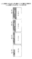
図2は本発明の一実施例で使用される周波数帯域を示す。説明の便宜上、具体的な数値が使用されるが数値は単なる一例にすぎず、様々な数値が使用されてもよい。通信システムに与えられた周波数帯域(全送信帯域)は一例として20MHzの帯域幅を有する。この全送信帯域は4つの周波数ブロック1〜4を含み、周波数ブロックの各々は1以上のサブキャリアを含むリソースブロックを複数個含む。図示の例では周波数ブロックの各々に多数のサブキャリアが含まれている様子が模式的に示される。本実施例では、通信が行われる帯域幅として、5MHz、10MHz、15MHz及び20MHzの4種類が用意されており、端末は、1以上の周波数ブロックを使用し、4つのうちの何れかの帯域幅で通信を行う。通信システム内で通信を行う端末は、4つのどの帯域ででも通信可能かもしれないし、何れかの帯域幅でしか通信できないかもしれない。ただし、少なくとも5MHzの帯域で通信できることが必要とされる。
FIG. 2 shows the frequency band used in one embodiment of the present invention. For convenience of explanation, specific numerical values are used, but the numerical values are merely examples, and various numerical values may be used. As an example, the frequency band (total transmission band) given to the communication system has a bandwidth of 20 MHz. The entire transmission band includes four
本実施例では、データチャネル(共有データチャネル)のスケジューリング内容を端末に通知するための制御チャネル(L1/L2制御シグナリングチャネル又は低レイヤ制御チャネル)は最小帯域幅(5MHz)で構成され、制御チャネルは各周波数ブロックで独立に用意される。例えば5MHzの帯域幅で通信を行う端末が、周波数ブロック1で通信を行う場合には、周波数ブロック1で用意される制御チャネルを受信し、スケジューリングの内容を得ることができる。端末がどの周波数ブロックで通信できるかについては例えば報知チャネルを用いて予め通知されてもよい。また、通信開始後に、使用する周波数ブロックが変更されてもよい。10MHzの帯域幅で通信を行う端末が、周波数ブロック1及び2で通信を行う場合には、端末は隣接する2つの周波数ブロックを使用し、周波数ブロック1及び2で用意される双方の制御チャネルを受信し、10MHzの範囲にわたるスケジューリングの内容を得ることができる。15MHzの帯域幅で通信を行う端末は、隣接する3つの周波数ブロックを使用し、周波数ブロック1,2及び3で通信を行う場合には、端末は周波数ブロック1,2及び3で用意される全ての制御チャネルを受信し、15MHzの範囲にわたるスケジューリングの内容を得ることができる。20MHzの帯域幅で通信を行う端末は、全ての周波数ブロックで用意される制御チャネルを全て受信し、20MHzの範囲にわたるスケジューリングの内容を得ることができる。
In this embodiment, the control channel (L1 / L2 control signaling channel or low layer control channel) for notifying the terminal of the scheduling content of the data channel (shared data channel) is configured with a minimum bandwidth (5 MHz), and the control channel Are prepared independently for each frequency block. For example, when a terminal that performs communication in a bandwidth of 5 MHz performs communication in the
図中、制御チャネルに関して周波数ブロックの中に4つの離散的なブロックが示されているが、これは制御チャネルがその周波数ブロック中の複数のリソースブロックに分散してマッピングされている様子を示す。制御チャネルの具体的なマッピング例については後述される。 In the figure, four discrete blocks are shown in the frequency block for the control channel, and this shows how the control channel is distributed and mapped to a plurality of resource blocks in the frequency block. A specific mapping example of the control channel will be described later.
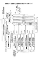
図3Aは本発明の一実施例による基地局の部分ブロック図を示す。図3Aには、周波数ブロック割当制御部31、周波数スケジューリング部32、周波数ブロック1での制御シグナリングチャネル生成部33−1及びデータチャネル生成部34−1、...周波数ブロックMでの制御シグナリングチャネル生成部33−M及びデータチャネル生成部34−M、報知チャネル(又はページングチャネル)生成部35、周波数ブロック1に関する第1多重部1−1、...周波数ブロックMに関する第1多重部1−M、第2多重部37、第3多重部38、他チャネル生成部39、逆高速フーリエ変換部40(IFFT)及びサイクリックプレフィックス(CP)付加部41が描かれている。
FIG. 3A shows a partial block diagram of a base station according to one embodiment of the present invention. 3A shows a frequency block
周波数ブロック割当制御部31は、端末(移動端末でも固定端末でもよい)から報告された通信可能な最大帯域幅に関する情報に基づいて、その端末が使用する周波数ブロックを確認する。周波数ブロック割当制御部31は個々の端末と周波数ブロックとの対応関係を管理し、その内容を周波数スケジューリング部32に通知する。ある帯域幅で通信可能な端末がどの周波数ブロックで通信してよいかについては、事前に報知チャネルで報知されていてもよい。例えば、報知チャネルは、5MHzの帯域幅で通信するユーザに対して、周波数ブロック1,2,3,4の何れかの帯域の使用を許可してもよいし、それらの内の何れかに使用が制限されてもよい。また、10MHzの帯域幅で通信するユーザに対して、周波数ブロック(1,2)、(2,3)又は(3,4)のような隣接する2つの周波数ブロックの組み合わせの使用が許可される。これら全ての使用が許可されてもよいし、或いは何れかの組み合わせに使用が制限されてもよい。15MHzの帯域幅で通信するユーザに対して、周波数ブロック(1,2,3)又は(2,3,4)のような隣接する3つの周波数ブロックの組み合わせの使用を許可する。双方の使用が許可されてもよいし、或いは一方の組み合わせに使用が制限されてもよい。20MHzの帯域幅で通信するユーザに対しては全ての周波数ブロックが使用される。使用可能な周波数ブロックは所定の周波数ホッピングパターンに従って通信開始後に変更されてもよい。
The frequency block
周波数スケジューリング部32は、複数の周波数ブロックの各々の中で周波数スケジューリングを行う。1つの周波数ブロック内での周波数スケジューリングは、端末から報告されたリソースブロック毎のチャネル状態情報CQIに基づいて、チャネル状態の良い端末にリソースブロックを優先的に割り当てるようにスケジューリング情報を決定する。
The
周波数ブロック1での制御シグナリングチャネル生成部33−1は、周波数ブロック1内のリソースブロックだけを用いて、周波数ブロック1内でのスケジューリング情報を端末に通知するための制御シグナリングチャネルを構成する。他の周波数ブロックも同様に、その周波数ブロック内のリソースブロックだけを用いて、その周波数ブロック内でのスケジューリング情報を端末に通知するための制御シグナリングチャネルを構成する。
The control signaling channel generation unit 33-1 in the
周波数ブロック1でのデータチャネル生成部34−1は、周波数ブロック1内の1以上のリソースブロックを用いて伝送されるデータチャネルを生成する。周波数ブロック1は1以上の端末(ユーザ)で共有されてよいので、図示の例ではN個のデータチャネル生成部1−1〜Nが用意されている。他の周波数ブロックについても同様に、その周波数ブロックを共有する端末のデータチャネルが生成される。
The data channel generation unit 34-1 in the
周波数ブロック1に関する第1多重部1−1は、周波数ブロック1に関する信号を多重化する。この多重化は少なくとも周波数多重を含む。制御シグナリングチャネル及びデータチャネルがどのように多重されるかについては後述される。他の第1多重部1−xも同様に周波数ブロックxで伝送される制御シグナリングチャネル及びデータチャネルを多重化する。
The first multiplexing unit 1-1 related to the
第2多重部37は、様々な多重部1−x(x=1,...,M)の周波数軸上での位置関係を所定のホッピングパターンに従って変更する動作を行うが、この機能については第2実施例で説明される。
The
報知チャネル(又はページングチャネル)生成部35は、局データのような配下の端末に通知するための報知情報を生成する。端末の通信可能な最大周波数帯域とその端末が使用可能な周波数ブロックとの関係を示す情報が制御情報に含まれてもよい。使用可能な周波数ブロックが様々に変更される場合には、それがどのように変化するかを示すホッピングパターンを指定する情報が報知情報に含まれてもよい。なお、ページングチャネルは、報知チャネルと同じ帯域で送信されてもよいし、各端末で使用される周波数ブロックで送信されてもよい。
The broadcast channel (or paging channel)
他チャネル生成部39は制御シグナリングチャネル及びデータチャネル以外のチャネルを生成する。例えば他チャネル生成部39はパイロットチャネルを生成する。
The other
第3多重部38は各周波数ブロックの制御シグナリングチャネル及びデータチャネルと、報知チャネル及び/又は他のチャネルとを必要に応じて多重化する。
The
逆高速フーリエ変換部40は第3多重部38から出力された信号を逆高速フーリエ変換し、OFDM方式の変調を行う。
The inverse fast
サイクリックプレフィックス(CP)付加部41はOFDM方式の変調後のシンボルにガードインターバルを付加し、送信シンボルを生成する。送信シンボルは例えばOFDMシンボルの末尾(又は先頭)の一連のデータを先頭(又は末尾)に付加することで作成されてもよい。
A cyclic prefix (CP) adding
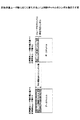
図3Bは図3AのCP付加部41に続く要素を示す。図示されているように、ガードインターバルの付加されたシンボルは、RF送信回路でディジタルアナログ変換、周波数変換及び帯域制限等の処理を経て、電力増幅器で適切な電力に増幅され、デュプレクサ及び送受信アンテナを介して送信される。
FIG. 3B shows elements following the
本発明に必須ではないが、本実施例では受信時に2アンテナによるアンテナダイバーシチ受信が行われる。2つのアンテナで受信された上り信号は、上り信号受信部に入力される。 Although not essential to the present invention, in this embodiment, antenna diversity reception by two antennas is performed during reception. Uplink signals received by the two antennas are input to the uplink signal receiver.
図4Aは1つの周波数ブロック(x番目の周波数ブロック)に関する信号処理要素を示す。xは1以上M以下の整数である。概して、周波数ブロックxに関する制御シグナリングチャネル生成部33−x及びデータチャネル生成部34−x、多重部43−A,B、多重部1−xが示されている。制御シグナリングチャネル生成部33−xは、不特定制御チャネル生成部41及び1以上の特定制御チャネル生成部42−A,B,...を有する。
FIG. 4A shows signal processing elements for one frequency block (xth frequency block). x is an integer of 1 or more and M or less. In general, a control signaling channel generation unit 33-x and a data channel generation unit 34-x, a multiplexing unit 43-A, B, and a multiplexing unit 1-x related to the frequency block x are illustrated. The control signaling channel generator 33-x includes an unspecific
不特定制御チャネル生成部41は制御シグナリングチャネルのうち、その周波数ブロックを使用する全ての端末が復号及び復調しなければならない不特定制御チャネル(不特定制御情報と呼んでもよい。)の部分にチャネル符号化及び多値変調を行い、それを出力する。
The unspecified control
特定制御チャネル生成部42−A,B,...は、制御シグナリングチャネルのうち、その周波数ブロックの中で1以上のリソースブロックの割り当てられた端末が復号及び復調しなければならない特定制御チャネル(特定制御情報と呼んでもよい。)の部分にチャネル符号化及び多値変調を行い、それを出力する。 Specific control channel generators 42-A, B,. . . Is a channel code in a part of a specific control channel (which may be referred to as specific control information) that must be decoded and demodulated by a terminal to which one or more resource blocks are allocated in the frequency block. And multi-level modulation and output it.
データチャネル生成部x−A,B,...は、個々の端末A,B,...宛のデータチャネルについてのチャネル符号化及び多値変調をそれぞれ行う。このチャネル符号化及び多値変調に関する情報は、上記の特定制御チャネルに含まれる。 Data channel generators x-A, B,. . . Are the individual terminals A, B,. . . Channel coding and multi-level modulation are performed for the data channel to which it is addressed. Information regarding this channel coding and multi-level modulation is included in the specific control channel.
多重部43−A,B,...は、リソースブロックの割り当てられた端末各々について特定制御チャネル及びデータチャネルをリソースブロックに対応付ける。 Multiplexers 43-A, B,. . . Associates a specific control channel and a data channel with a resource block for each terminal to which the resource block is assigned.
上述したように不特定制御チャネルについての符号化(及び変調)は不特定制御チャネル生成部41で行われ、特定制御チャネルについての符号化(及び変調)は特定制御チャネル生成部42−A,B,...で個々に行われる。従って、本実施例では図6に概念的に示されるように、不特定制御チャネルは、周波数ブロックxが割り当てられているユーザ全員分の情報を含み、それらはまとめて誤り訂正符号化の対象になる。
As described above, the coding (and modulation) for the unspecified control channel is performed by the unspecified control
別の実施例では不特定制御チャネルもユーザ毎に誤り訂正符号化されてもよい。この場合、各ユーザは個々に誤り訂正符号化されたブロックのどれに自局の情報が含まれているかを一義的には特定できないので、全てのブロックをデコードする必要がある。この別の実施例では符号化の処理がユーザ毎に閉じているので、ユーザの追加及び変更が比較的容易である。各ユーザはユーザ全員分の不特定制御チャネルをデコードし、復調する必要がある。 In another embodiment, the unspecified control channel may also be error correction coded for each user. In this case, each user cannot uniquely identify which of the individual error correction coded blocks contains the information of the own station, so it is necessary to decode all the blocks. In this alternative embodiment, since the encoding process is closed for each user, addition and change of users are relatively easy. Each user needs to decode and demodulate the unspecified control channel for all the users.
これに対して、特定制御チャネルは、実際にリソースブロックの割り当てられたユーザに関する情報しか含まず、ユーザ毎に誤り訂正符号化される。リソースブロックの割り当てられたユーザが誰であるかは、不特定制御チャネルをデコード及び復調することで判明する。従って特定制御チャネルは全員がデコードする必要はなく、リソースブロックの割り当てられたユーザだけがデコードすればよい。なお、特定制御チャネルについてのチャネル符号化率や変調方式は通信中に適宜変更されるが、不特定制御チャネルについてのチャネル符号化率や変調方式は固定されていてもよい。ただし、一定以上の信号品質を確保するため送信電力制御(TPC)が行われることが望ましい。特定制御チャネルは誤り訂正符号化が施された上で良好なリソースブロックで伝送される。従って、パンクチャリングを行うことで下りデータ量がある低度減らされてもよい。 On the other hand, the specific control channel includes only information related to users to which resource blocks are actually allocated, and is error-correction coded for each user. The user to whom the resource block is assigned can be determined by decoding and demodulating the unspecified control channel. Therefore, it is not necessary for everyone to decode the specific control channel, and only the user to whom the resource block is assigned needs to decode it. Note that the channel coding rate and the modulation scheme for the specific control channel are appropriately changed during communication, but the channel coding rate and the modulation scheme for the non-specific control channel may be fixed. However, it is desirable to perform transmission power control (TPC) to ensure a certain level of signal quality. The specific control channel is transmitted with a good resource block after being subjected to error correction coding. Therefore, the amount of downlink data may be reduced to a certain degree by performing puncturing.
図5Aは下り制御シグナリングチャネルの種類及び情報項目の一例を示す。下り制御シグナリングチャネルには、報知チャネル(BCH)、個別L3シグナリングチャネル(上位レイヤ制御チャネル)及びL1/L2制御チャネル(低レイヤ制御チャネル)が含まれる。L1/L2制御チャネルには下りデータ伝送用の情報だけでなく上りデータ伝送用の情報が含まれてもよい。また、L1/L2制御チャネルにはL1/L2制御チャネルの伝送フォーマット(データ変調方式及びチャネル符号化率、同時割り当てユーザ数等)が含まれてもよい。以下、各チャネルで伝送される情報項目を概説する。 FIG. 5A shows an example of the types and information items of the downlink control signaling channel. The downlink control signaling channel includes a broadcast channel (BCH), a dedicated L3 signaling channel (upper layer control channel), and an L1 / L2 control channel (lower layer control channel). The L1 / L2 control channel may include not only information for downlink data transmission but also information for uplink data transmission. The L1 / L2 control channel may include the transmission format of the L1 / L2 control channel (data modulation scheme, channel coding rate, number of simultaneously allocated users, etc.). The information items transmitted in each channel will be outlined below.
(報知チャネル)
報知チャネルはセル内で不変な情報や低速で変化する情報を通信端末(移動端末でも固定端末でもよく、ユーザ装置と呼ばれてもよい)に通知するのに使用される。例えば1000ms(1秒)程度の周期で変化してよい情報は、報知情報として通知されてもよい。報知情報には、下りL1/L2制御チャネルの伝送フォーマット、同時割当最大ユーザ数、リソースブロック配置情報及びMIMO方式情報が含まれてもよい。
(Broadcast channel)
The broadcast channel is used to notify a communication terminal (which may be a mobile terminal or a fixed terminal or may be referred to as a user apparatus) of information that does not change in a cell or information that changes at a low speed. For example, information that may change at a cycle of about 1000 ms (1 second) may be notified as broadcast information. The broadcast information may include the transmission format of the downlink L1 / L2 control channel, the maximum number of simultaneously allocated users, resource block arrangement information, and MIMO scheme information.
伝送フォーマットは、データ変調方式とチャネル符号化率で特定される。チャネル符号化率の代わりに、データサイズが通知されてもよい。データ変調方式とデータサイズからチャネル符号化率が一意に導出可能だからである。なお、この伝送フォーマットは後述されるL1/L2制御チャネル内(パート0)で通知されてもよい。 The transmission format is specified by the data modulation scheme and the channel coding rate. The data size may be notified instead of the channel coding rate. This is because the channel coding rate can be uniquely derived from the data modulation scheme and data size. This transmission format may be notified in the L1 / L2 control channel (part 0) described later.
同時割当最大ユーザ数は、1TTIに,FDM、CDM及びTDMの1以上を用いて多重可能な最大数を表す。この数は上りチャネル及び下りチャネルで同じでもよいし、異なってもよい。 The maximum number of simultaneously allocated users represents the maximum number that can be multiplexed using one or more of FDM, CDM, and TDM in 1 TTI. This number may be the same for the uplink channel and the downlink channel, or may be different.
リソースブロック配置情報は、そのセルで使用されるリソースブロックの周波数,時間軸上での位置を特定するための情報である。本実施例では、周波数分割多重(FDM)方式としてローカライズド(localized)FDM方式と、ディストリビュート(distributed)FDM方式の2種類を利用可能である。ローカライズドFDM方式では、周波数軸上で局所的に良いチャネル状態のユーザに優先的に連続的な帯域が割り当てられる。この方式は、移動度の小さなユーザの通信や、高品質で大容量のデータ伝送等に有利である。ディストリビュートFDM方式では、広帯域に渡って断続的に複数の周波数成分を有するように下り信号が作成される。この方式は、移動度の大きなユーザの通信や、音声パケット(VoIP)のような周期的且つ小さなデータサイズのデータ伝送等に有利である。何れの方式が使用されるにせよ、周波数リソースは連続的な帯域又は離散的な複数の周波数成分を特定する情報に従って、リソースの割り当てが行われる。 The resource block arrangement information is information for specifying the frequency block and the position on the time axis of the resource block used in the cell. In this embodiment, two types of frequency division multiplexing (FDM) systems, a localized FDM system and a distributed FDM system, can be used. In the localized FDM scheme, a continuous band is preferentially allocated to users in a channel state that is locally good on the frequency axis. This method is advantageous for communication of users with low mobility, high-quality and large-capacity data transmission, and the like. In the distributed FDM system, a downlink signal is created so as to have a plurality of frequency components intermittently over a wide band. This method is advantageous for communication of users with high mobility, data transmission of periodic and small data size such as voice packet (VoIP), and the like. Regardless of which method is used, the frequency resource is allocated according to information specifying a continuous band or a plurality of discrete frequency components.
図5B上側に示されるように、例えば、ローカライズドFDM方式でリソースが「4番」で特定される場合には、フィジカルリソースブロック番号4のリソースが使用される。図5B下側に示されるようなディストリビュートFDM方式で、「4番」でリソースが特定される場合には、フィジカルリソースブロック2,8の左半分2つが使用される。図示の例では、1つのフィジカルリソースブロックが2つに分割されている。ディストリビュートFDM方式における番号付けや分割数はセル毎に異なってよい。このため、リソースブロック配置情報が報知チャネルでセル内の通信端末に通知される。
As shown in the upper part of FIG. 5B, for example, when the resource is specified as “No. 4” in the localized FDM method, the resource of physical
MIMO方式情報は、基地局に複数のアンテナが用意されている場合に、シングルユーザマイモ(SU-MIMO: Single User - Multi Input Multi Output)方式又はマルチユーザマイモ(MU-MIMO: Multi - User MIMO)方式の何れが行われるかが示される。SU-MIMO方式は複数アンテナの通信端末1台と通信を行う方式であり、MU-MIMO方式は1アンテナの通信端末複数台と同時に通信を行う方式である。 MIMO system information includes single user mimo (SU-MIMO) or multi user mimo (MU-MIMO: Multi-User MIMO) when multiple antennas are prepared in the base station. Which of the schemes is performed is indicated. The SU-MIMO method is a method for communicating with one communication terminal having a plurality of antennas, and the MU-MIMO method is a method for performing communication simultaneously with a plurality of communication terminals having one antenna.
(個別L3シグナリングチャネル)
個別L3シグナリングチャネルも、例えば1000ms周期のような低速で変化する情報を通信端末に通知するのに使用される。報知チャネルはセル内の全通信端末に通知されるが、個別L3シグナリングチャネルは特定の通信端末にしか通知されない。個別L3シグナリングチャネルには、FDM方式の種別及びパーシステントスケジューリング情報が含まれる。個別L3シグナリングチャネルは、特定制御チャネルに分類されてもよい。
(Dedicated L3 signaling channel)
The dedicated L3 signaling channel is also used to notify the communication terminal of information that changes at a low speed such as a period of 1000 ms. The broadcast channel is notified to all communication terminals in the cell, but the dedicated L3 signaling channel is notified only to a specific communication terminal. The dedicated L3 signaling channel includes the FDM type and persistent scheduling information. The dedicated L3 signaling channel may be classified as a specific control channel.
FDM方式の種別は、特定された個々の通信端末がローカライズドFDM方式又はディストリビュートFDM方式の何れで多重されるかを指示する。 The type of the FDM system indicates whether the specified individual communication terminal is multiplexed by the localized FDM system or the distributed FDM system.
パーシステントスケジューリング情報は、パーシステント(Persistent)スケジューリングが行われる場合に、上り又は下りデータチャネルの伝送フォーマット(データ変調方式及びチャネル符号化率)や、使用されるリソースブロック等を特定する。 The persistent scheduling information specifies the transmission format (data modulation scheme and channel coding rate) of the uplink or downlink data channel, the resource block to be used, etc. when persistent scheduling is performed.
(L1/L2制御チャネル)
下りL1/L2制御チャネルには、下りリンクのデータ伝送に関連する情報だけでなく、上りリンクのデータ伝送に関連する情報が含まれてもよい。更に、L1/L2制御チャネルの伝送フォーマットを示す情報ビット(パート0)が含まれてもよい。下りリンクのデータ伝送に関連する情報は以下のようにパート1、パート2a及びパート2bの3種類に分類できる。パート1及びパート2aは不特定制御チャネルに分類でき、パート2bは特定制御チャネルに分類できる。
(L1 / L2 control channel)
The downlink L1 / L2 control channel may include not only information related to downlink data transmission but also information related to uplink data transmission. Furthermore, an information bit (part 0) indicating the transmission format of the L1 / L2 control channel may be included. Information related to downlink data transmission can be classified into three types,
(パート0)
パート0には、L1/L2制御チャネルの伝送フォーマット(変調方式及びチャネル符号化率、同時割当ユーザ数又は全体の制御ビット数)が含まれる。L1/L2制御チャネルの伝送フォーマットとして報知チャネルで通知される情報を用いる場合には、パート0には、同時割当ユーザ数(又は全体の制御ビット数)が含まれる。
(Part 0)
L1/L2制御チャネルに必要なシンボル数は、同時多重ユーザ数及び多重するユーザの受信品質に依存する。図5C左側に示されるように、典型的にはL1/L2制御チャネルのシンボル数を十分に大きくしておく。シンボル数を変更する場合には、報知チャネルで通知されるL1/L2制御チャネルの伝送フォーマットによって、例えば1000ms(1秒)程度の周期で制御することができる。しかし、図5C右側に示されるように同時多重ユーザ数が小さければ、制御チャネルとして必要なシンボル数は少なくなる。従って、短い周期で同時多重ユーザ数及び多重するユーザの受信品質が変化する場合には、十分大きく確保されているL1/L2制御チャネルに無駄が生じる場合がある。 The number of symbols required for the L1 / L2 control channel depends on the number of simultaneously multiplexed users and the reception quality of the users to be multiplexed. As shown in the left side of FIG. 5C, typically, the number of symbols of the L1 / L2 control channel is made sufficiently large. When changing the number of symbols, control can be performed with a period of about 1000 ms (1 second), for example, according to the transmission format of the L1 / L2 control channel notified by the broadcast channel. However, if the number of simultaneously multiplexed users is small as shown on the right side of FIG. 5C, the number of symbols required for the control channel is reduced. Therefore, when the number of simultaneously multiplexed users and the reception quality of the users to be multiplexed change in a short period, there may be waste in the L1 / L2 control channel that is secured sufficiently large.
このようなL1/L2制御チャネルの無駄を低減するため、L1/L2制御チャネル内で、変調方式及びチャネル符号化率、同時割当ユーザ数(又は全体の制御ビット数)を通知してもよい。L1/L2制御チャネル内で変調方式及びチャネル符号化率を通知することで、報知チャネルによる通知より短い周期で変調方式及びチャネル符号化率を変更することが可能になる。 In order to reduce the waste of the L1 / L2 control channel, the modulation scheme, the channel coding rate, and the number of simultaneously allocated users (or the total number of control bits) may be notified in the L1 / L2 control channel. By notifying the modulation scheme and channel coding rate in the L1 / L2 control channel, it becomes possible to change the modulation scheme and channel coding rate in a shorter cycle than the notification by the broadcast channel.
(パート1)
パート1には、ページングインジケータ(PI)が含まれる。各通信端末はページングインジケータを復調することで、自端末に対する呼出がなされているか否かを確認できる。
(Part 1)
(パート2a)
パート2aには、下りデータチャネルのリソース割当情報、割当時間長及びMIMO情報が含まれる。
(Part 2a)
Part 2a includes resource allocation information, allocation time length, and MIMO information of the downlink data channel.
下りデータチャネルのリソース割当情報は、下りデータチャネルが含まれているリソースブロックを特定する。リソースブロックの特定については、当該技術分野で既知の様々な方法が使用可能である。例えば、ビットマップ方式、ツリー分岐番号方式等が使用されてもよい。 The resource allocation information of the downlink data channel specifies a resource block including the downlink data channel. Various methods known in the art can be used for specifying the resource block. For example, a bitmap method, a tree branch number method, or the like may be used.
割当時間長は、下りデータチャネルがどの程度の期間連続して伝送されるかを示す。最も頻繁にリソース割当内容が変わる場合は、TTI毎であるが、オーバーヘッドを削減する観点から、複数のTTIにわたって同じリソース割当内容でデータチャネルが伝送されてもよい。 The allocated time length indicates how long the downlink data channel is continuously transmitted. The resource allocation contents change most frequently every TTI, but from the viewpoint of reducing overhead, the data channel may be transmitted with the same resource allocation contents over a plurality of TTIs.
MIMO情報は、通信にMIMO方式が使用される場合に、アンテナ数、ストリーム数等を指定する。ストリーム数は情報系列数と呼んでもよい。 The MIMO information specifies the number of antennas, the number of streams, and the like when the MIMO scheme is used for communication. The number of streams may be called the number of information sequences.
なお、パート2aにユーザ識別情報が含まれることは必須でないが、その全部又は一部が含まれてもよい。 In addition, although it is not essential that the part 2a includes user identification information, it may be included in whole or in part.
(パート2b)
パート2bには、MIMO方式が使用される場合のプリコーディング情報、下りデータチャネルの伝送フォーマット、ハイブリッド再送制御(HARQ)情報及びCRC情報が含まれる。
(Part 2b)
Part 2b includes precoding information, a downlink data channel transmission format, hybrid retransmission control (HARQ) information, and CRC information when the MIMO scheme is used.
MIMO方式が使用される場合のプリコーディング情報は、複数のアンテナの個々に適用される重み係数を特定する。各アンテナに適用される重み係数を調整することで、通信信号の指向性が調整される。 The precoding information when the MIMO scheme is used specifies a weighting factor applied to each of a plurality of antennas. The directivity of the communication signal is adjusted by adjusting the weighting coefficient applied to each antenna.
下りデータチャネルの伝送フォーマットは、データ変調方式とチャネル符号化率で特定される。チャネル符号化率の代わりに、データサイズ又はペイロードサイズが通知されてもよい。データ変調方式とデータサイズからチャネル符号化率が一意に導出可能だからである。 The transmission format of the downlink data channel is specified by the data modulation scheme and the channel coding rate. Instead of the channel coding rate, the data size or the payload size may be notified. This is because the channel coding rate can be uniquely derived from the data modulation scheme and data size.
ハイブリッド再送制御(HARQ: Hybrid Automatic Repeat ReQuest)情報は、下りパケットの再送制御に必要な情報を含む。具体的には、再送制御情報は、プロセス番号、パケット合成法を示す冗長バージョン情報、及び新規パケットであるか再送パケットであるかを見分けるための新旧インジケータ(New Data Indicator)を含む。 Hybrid retransmission control (HARQ: Hybrid Automatic Repeat ReQuest) information includes information necessary for downlink packet retransmission control. Specifically, the retransmission control information includes a process number, redundant version information indicating a packet combining method, and a new and old indicator (New Data Indicator) for distinguishing whether the packet is a new packet or a retransmission packet.
CRC情報は、誤り検出に巡回冗長検査法が使用される場合に、ユーザ識別情報(UE-ID)が畳み込まれたCRC検出ビットを示す。 CRC information indicates a CRC detection bit in which user identification information (UE-ID) is convoluted when the cyclic redundancy check method is used for error detection.
上りリンクのデータ伝送に関連する情報は以下のようにパート1乃至パート4の4種類に分類できる。これらの情報は、原則として不特定制御チャネルに分類されてよいが、下りデータチャネル用にリソースが割り当てられている通信端末に対しては、特定制御チャネルとして伝送されてもよい。
Information related to uplink data transmission can be classified into four types of
(パート1)
パート1には、過去の上りデータチャネルに対する送達確認情報が含まれる。送達確認情報は、パケットに誤りがなかったこと若しくはあったとしても許容範囲内であったことを示す肯定応答(ACK)、或いはパケットに許容範囲を超える誤りがあったことを示す否定応答(NACK)を示す。
(Part 1)
(パート2)
パート2には、将来の上りデータチャネルに対するリソース割当情報、その上りデータチャネルの伝送フォーマット、送信電力情報及びCRC情報が含まれる。
(Part 2)
リソース割当情報は、上りデータチャネルの送信に使用可能なリソースブロックを特定する。リソースブロックの特定については、当該技術分野で既知の様々な方法が使用可能である。例えば、ビットマップ方式、ツリー分岐番号方式等が使用されてもよい。 The resource allocation information specifies resource blocks that can be used for uplink data channel transmission. Various methods known in the art can be used for specifying the resource block. For example, a bitmap method, a tree branch number method, or the like may be used.
上りデータチャネルの伝送フォーマットは、データ変調方式とチャネル符号化率で特定される。チャネル符号化率の代わりに、データサイズ又はペイロードサイズが通知されてもよい。データ変調方式とデータサイズからチャネル符号化率が一意に導出可能だからである。 The transmission format of the uplink data channel is specified by the data modulation scheme and the channel coding rate. Instead of the channel coding rate, the data size or the payload size may be notified. This is because the channel coding rate can be uniquely derived from the data modulation scheme and data size.
送信電力情報は、上りデータチャネルがどの程度の電力で送信されるべきかを示す。 The transmission power information indicates how much power the uplink data channel should be transmitted.
CRC情報は、誤り検出に巡回冗長検査法が使用される場合に、ユーザ識別情報(UE-ID)が畳み込まれたCRC検出ビットを示す。なお、ランダムアクセスチャネル(RACH)に対する応答信号(下りL1/L2制御チャネル)では、UE-IDとして、RACHプリアンブルのランダムIDが使用されてもよい。 CRC information indicates a CRC detection bit in which user identification information (UE-ID) is convoluted when the cyclic redundancy check method is used for error detection. In the response signal (downlink L1 / L2 control channel) for the random access channel (RACH), the random ID of the RACH preamble may be used as the UE-ID.
(パート3)
パート3には、送信タイミング制御ビットが含まれる。これは、セル内の通信端末間の同期をとるための制御ビットである。
(Part 3)
(パート4)
パート4は通信端末の送信電力に関する送信電力情報を含み、この情報は、上りデータチャネルの伝送用にリソースが割り当てられなかった通信端末が、例えば下りチャネルのCQIを報告するためにどの程度の電力で上り制御チャネルを送信すべきかを示す。
(Part 4)
図4Bは図4Aと同様に、1つの周波数ブロックに関する信号処理要素を示すが、個々の制御情報を具体的に明示している点で図4Aと異なって見える。図4A及び図4Bで同じ参照符号は同じ要素を示す。図中、「リソースブロック内マッピング」とは特定の通信端末に割り当てられた1以上のリソースブロックに限定してマッピングされることを示す。「リソースブロック外マッピング」とは多数のリソースブロックを含む周波数ブロック全域にわたってマッピングされることを示す。L1/L2制御チャネル内のパート0は、不特定制御チャネルとして周波数ブロック全域で送信される。L1/L2制御チャネルの内の上りデータ伝送に関連する情報(パート1〜4)は、下りデータチャネル用にリソースが割り当てられていれば特定制御チャネルとしてそのリソースで、そうでなければ不特定制御チャネルとして周波数ブロック全域で送信される。
FIG. 4B shows signal processing elements related to one frequency block, similar to FIG. 4A, but looks different from FIG. 4A in that each control information is clearly specified. The same reference numerals in FIGS. 4A and 4B indicate the same elements. In the figure, “mapping within a resource block” indicates that mapping is limited to one or more resource blocks assigned to a specific communication terminal. “Outside resource block mapping” indicates mapping across the entire frequency block including a large number of resource blocks.
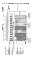
図7Aはデータチャネル及び制御チャネルのマッピング例を示す。図示のマッピング例は、1つの周波数ブロック及び1つのサブフレームに関するものであり、概して第1多重部1−xの出力内容に相当する(但し、パイロットチャネル等は第3多重部38で多重される。)。1つのサブフレームは例えば1つの送信時間間隔(TTI)に対応してもよいし、複数のTTIに対応してもよい。図示の例では、周波数ブロックに7つのリソースブロックRB1〜7が含まれている。この7つのリソースブロックは、図3Aの周波数スケジューリング部32によって、チャネル状態の良い端末に割り当てられる。
FIG. 7A shows an example of data channel and control channel mapping. The illustrated mapping example relates to one frequency block and one subframe, and generally corresponds to the output content of the first multiplexing unit 1-x (however, the pilot channel and the like are multiplexed by the third multiplexing unit 38). .) One subframe may correspond to, for example, one transmission time interval (TTI) or may correspond to a plurality of TTIs. In the illustrated example, seven resource blocks RB1 to RB7 are included in the frequency block. These seven resource blocks are allocated to terminals having good channel states by the
概して、不特定制御チャネル等、パイロットチャネル等及びデータチャネル等は時間多重されている。不特定制御チャネル(L1/L2制御チャネル内のパート0を含む)は周波数ブロックの全域にわたって分散してマッピングされている。即ち不特定制御チャネルは7つのリソースブロックの占める帯域全体にわたって分散している。図示の例では不特定制御チャネル(L1/L2制御チャネル内のパート0を含む)をと他の制御チャネル(特定制御チャネルを除く)とが周波数多重されている。他のチャネルには例えば同期チャネル等が含まれてもよい。特にL1/L2制御チャネル内のパート0は、遅延時間を短くする必要があるため、先頭OFDMシンボルに多重することが好ましい。図示の例では不特定制御チャネル及び他の制御チャネルは、何らかの間隔を隔てて並んだ複数の周波数成分を各々が有するように周波数多重される。このような多重化方式は、ディストリビュート周波数分割多重化(distributed FDM)方式と呼ばれる。ディストリビュートFDM方式は周波数ダイバーシチ効果が得られる点で有利である。周波数成分同士の間隔は全て同じでもよいし異なっていてもよい。いずれにせよ、不特定制御チャネルが1つの周波数ブロックの全域にわたって分散していることを要する。更に、別法としてCDM方式を適用することも可能である。CDM方式では周波数ダイバーシチ効果が更に大きくなるという利点がある一方で、直交性の崩れによる受信品質の劣化が生じる欠点もある。
In general, unspecified control channels, pilot channels, and data channels are time-multiplexed. Unspecified control channels (including
図示の例ではパイロットチャネル等も周波数ブロック全域にわたってマッピングされている。様々な周波数成分についてのチャネル推定等を正確に行う観点からは、図示のようにパイロットチャネルが広範囲にマッピングされていることが望ましい。 In the illustrated example, pilot channels and the like are also mapped over the entire frequency block. From the viewpoint of accurately performing channel estimation and the like for various frequency components, it is desirable that the pilot channel is mapped over a wide range as illustrated.
図示の例ではリソースブロックRB1,RB2,RB4はユーザ1(UE1)に割り当てられ、リソースブロックRB3,RB5,RB6はユーザ2(UE2)に割り当てられ、リソースブロックRB7はユーザ3(UE3)に割り当てられる。上述したようにこのような割り当て情報は不特定制御チャネルに含まれている。更に、ユーザ1に割り当てられたリソースブロックの内のリソースブロックRB1の先頭に、ユーザ1に関する特定制御チャネルがマッピングされている。ユーザ2に割り当てられたリソースブロックの内のリソースブロックRB3の先頭には、ユーザ2に関する特定制御チャネルがマッピングされている。ユーザ3に割り当てられたリソースブロックRB7の先頭には、ユーザ3に関する特定制御チャネルがマッピングされている。図中、ユーザ1,2,3の特定制御チャネルの占める大きさが不均一に描かれている点に留意を要する。これは、特定制御チャネルの情報量がユーザにより異なってよいことを表す。特定制御チャネルはデータチャネルに割り当てられたリソースブロックに限定して局所的にマッピングされる。この点、様々なリソースブロックにわたって分散してマッピングされるディストリビュートFDMと異なり、このようなマッピング方式はローカライズド周波数分割多重(localized FDM)とも呼ばれる。
In the illustrated example, resource blocks RB1, RB2, and RB4 are assigned to user 1 (UE1), resource blocks RB3, RB5, and RB6 are assigned to user 2 (UE2), and resource block RB7 is assigned to user 3 (UE3). . As described above, such allocation information is included in the unspecified control channel. Furthermore, a specific control channel for
図7Bは不特定制御チャネルの別のマッピング例を示す。ユーザ1(UE1)の特定制御チャネルは、図7Aでは1つのリソースブロックRB1だけにマッピングされていたが、図7BではリソースブロックRB1,RB2,RB4全体(ユーザ1に割り当てられたリソースブロック全体)にわたってディストリビュートFDM方式で離散的に分散してマッピングされている。また、ユーザ2(UE2)に関する特定制御チャネルも、図7Aに示される場合とは異なり、リソースブロックRB3,RB5,RB6全体にわたってマッピングされている。ユーザ2の特定制御チャネルと共有データチャネルは時分割多重されている。このように、各ユーザの特定制御チャネル及び共有データチャネルは、各ユーザに割り当てられた1以上のリソースブロックの全部又は一部の中で、時分割多重(TDM)方式で及び/又は周波数分割多重方式で(ローカライズドFDM方式及びディストリビュートFDM方式を含む)多重されてもよい。2以上のリソースブロックにわたって特定制御チャネルをマッピングすることで、特定制御チャネルについても周波数ダイバーシチ効果を期待することができ、特定制御チャネルの更なる信号品質の向上を図ることができる。
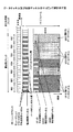
FIG. 7B shows another example of mapping of unspecified control channels. The specific control channel of user 1 (UE1) is mapped to only one resource block RB1 in FIG. 7A, but over the entire resource blocks RB1, RB2, and RB4 (entire resource blocks assigned to user 1) in FIG. 7B. The distributed FDM method is discretely distributed and mapped. Also, the specific control channel for user 2 (UE2) is also mapped over the entire resource blocks RB3, RB5, RB6, unlike the case shown in FIG. 7A.
次にL1/L2制御チャネル内のパート0の具体的なフォーマットを説明する。
Next, a specific format of
図7CはL1/L2制御チャネルのシンボル数(又は同時割当ユーザ数)をパート0で通知する場合のL1/L2制御チャネルのフォーマットを示す例である。通信端末が報知チャネルで通知された変調方式及び符号化率(MCS: Modulation and Coding Scheme)を用いる場合、同時割当ユーザ数に応じてL1/L2制御チャネルに必要なシンボル数が変わってくる。これを識別するために、L1/L2制御チャネルのパート0の情報として、制御ビット(図7Cでは2ビット)が設けられている。例えば00の制御ビットをパート0の情報として通知することにより、通信端末でこの制御ビットを復号してL1/L2制御チャネルのシンボル数が100であることを知ることができる。なお、図7Cの先頭の2ビットがパート0に相当し、可変の制御チャネルが不特定制御チャネル(下りの場合はパート1及びパート2a)に相当する。また、図7Cでは報知チャネルでMCSが通知されているが、L3シグナリングチャネルでMCSが通知されてもよい。
FIG. 7C shows an example of the format of the L1 / L2 control channel when the number of symbols (or the number of simultaneously allocated users) of the L1 / L2 control channel is notified in
図7Dは各MCSの同時割当ユーザ数をパート0で通知する場合のL1/L2制御チャネルのフォーマットを示す例である。予め決められた種類のMCSの中から通信端末の受信品質に応じて適切なMCSを用いる場合に、通信端末の受信品質に応じてL1/L2制御チャネルに必要なシンボル数が変わってくる。これを識別するために、L1/L2制御チャネルのパート0の情報として、制御ビット(図7Dでは8ビット)が設けられている。図7Dでは、一例として4種類のMCSが存在し、各MCSの同時割当ユーザ数の最大値が3である場合を示している。同時割当ユーザ数が0〜3であるため、この情報は2ビットで表すことができる(00=0ユーザ、01=1ユーザ、10=2ユーザ、11=3ユーザ)。各MCSについて2ビットが必要になるため、この場合のパート0は8ビットとなる。例えば、01100001の制御ビットをパート0の情報として通知することにより、通信端末でこの制御ビットに基づいて自分の受信品質に応じた制御情報(下りの場合はパート2a)を知ることができる。
FIG. 7D is an example showing the format of the L1 / L2 control channel when the number of simultaneously allocated users of each MCS is notified in
図7Eは3セクタ構成の場合でのL1/L2制御チャネル内の情報ビット(パート0)のマッピングを示す例である。3セクタ構成の場合には、L1/L2制御チャネルの伝送フォーマットを示す情報ビット(パート0)を送信するために3種類のパターンを用意しておき、それぞれのパターンが周波数領域で重ならないように各セクタに割り当ててもよい。隣接セクタ(又はセル)での送信パターンが互いに異なるようにパターンを選択することで、干渉コーディネーションの効果を得ることが可能になる。 FIG. 7E is an example showing mapping of information bits (part 0) in the L1 / L2 control channel in the case of a three-sector configuration. In the case of a three-sector configuration, three types of patterns are prepared for transmitting information bits (part 0) indicating the transmission format of the L1 / L2 control channel so that the patterns do not overlap in the frequency domain. It may be assigned to each sector. By selecting patterns so that transmission patterns in adjacent sectors (or cells) are different from each other, the effect of interference coordination can be obtained.
図7Fは様々な多重法の例を示す。上記の例では様々な不特定制御チャネルはディストリビュートFDM方式で多重されているが、符号分割多重(CDM)方式や時分割多重(TDM)方式のような適切な様々な多重法が使用されてもよい。図7F(1)はディストリビュートFDM方式で多重が行われる様子を示す。離散的な複数の周波数成分を特定する番号1,2,3,4を用いることで、各ユーザの信号を適切に直交させることができる。ただし,この例のように規則的でなくてもよい。また,隣接するセル間で異なる規則を用いることで,送信電力制御を行ったときの干渉量をランダム化することができる。図7F(2)は符号分割多重(CDM)方式で多重が行われる様子を示す。コード1,2,3,4を用いることで、各ユーザの信号を適切に直交させることができる。図7F(3)はディストリビュートFDM方式で、ユーザ多重数が3に変わった場合の様子を示す。離散的な複数の周波数成分を特定する番号1,2,3を再定義することで、各ユーザの信号を適切に直交させることができる。同時割当ユーザ数が最大数未満であった場合は、図7F(4)に示されるように、基地局は下り制御チャネルの送信電力を増やしてもよい。また,CDMとFDMのハイブリッドも適用可能である。
FIG. 7F shows examples of various multiplexing methods. In the above example, various unspecified control channels are multiplexed using the distributed FDM method, but various appropriate multiplexing methods such as code division multiplexing (CDM) and time division multiplexing (TDM) are used. Also good. FIG. 7F (1) shows a state in which multiplexing is performed by the distributed FDM method. By using
図8Aは本発明の一実施例で使用される移動端末の部分ブロック図を示す。図8Aにはキャリア周波数同調部81、フィルタリング部82、サイクリックプレフィックス(CP)除去部83、高速フーリエ変換部(FFT)84、CQI測定部85、報知チャネル(又はページングチャネル)復号部86、不特定制御チャネル(パート0)復号部87−0、不特定制御チャネル復号部87、特定制御チャネル復号部88及びデータチャネル復号部89が描かれている。
FIG. 8A shows a partial block diagram of a mobile terminal used in one embodiment of the present invention. 8A shows a carrier
キャリア周波数同調部81は端末に割り当てられている周波数ブロックの信号を受信できるように受信帯域の中心周波数を適切に調整する。
The carrier
フィルタリング部82は受信信号をフィルタリングする。
The
サイクリックプレフィックス除去部83は受信信号からガードインターバルを除去し、受信シンボルから有効シンボル部分を抽出する。 The cyclic prefix removing unit 83 removes the guard interval from the received signal and extracts the effective symbol portion from the received symbol.
高速フーリエ変換部(FFT)84は有効シンボルに含まれる情報を高速フーリエ変換し、OFDM方式の復調を行う。 A fast Fourier transform unit (FFT) 84 performs fast Fourier transform on information included in the effective symbol and performs OFDM demodulation.
CQI測定部85は受信信号に含まれているパイロットチャネルの受信電力レベルを測定し、測定結果をチャネル状態情報CQIとして基地局にフィードバックする。CQIは周波数ブロック内の全てのリソースブロック毎に行われ、それらが全て基地局に報告される。
報知チャネル(又はページングチャネル)復号部86は報知チャネルを復号する。ページングチャネルが含まれている場合にはそれも復号する。
The broadcast channel (or paging channel)
不特定制御チャネル(パート0)復号部87−0はL1/L2制御チャネル内のパート0の情報を復号する。このパート0により、不特定制御チャネルの伝送フォーマットを認識することが可能になる。
The unspecified control channel (part 0) decoding unit 87-0 decodes the information of
不特定制御チャネル復号部87は受信信号に含まれている不特定制御チャネルを復号し、スケジューリング情報を抽出する。スケジューリング情報には、その端末宛の共有データチャネルにリソースブロックが割り当てられているか否かを示す情報、割り当てられている場合にはリソースブロック番号を示す情報等が含まれる。
The unspecified control
特定制御チャネル復号部88は受信信号に含まれている特定制御チャネルを復号する。特定制御チャネルは共有データチャネルに関するデータ変調、チャネル符号化率及びHARQの情報が含まれる。
The specific control
データチャネル復号部89は、特定制御チャネルから抽出した情報に基づいて、受信信号に含まれている共有データチャネルを復号する。復号結果に応じて肯定応答(ACK)又は否定応答(NACK)が基地局に報告されてもよい。
The data
図8Bは図8Aと同様に、移動端末の部分ブロック図を示すが、個々の制御情報を具体的に明示している点で図8Aと異なって見える。図8A及び図8Bで同じ参照符号は同じ要素を示す。図中、「リソースブロック内デマッピング」とは特定の通信端末に割り当てられた1以上のリソースブロックに限定してマッピングされた情報を抽出することを示す。「リソースブロック外デマッピング」とは多数のリソースブロックを含む周波数ブロック全域にわたってマッピングされた情報を抽出することを示す。 FIG. 8B shows a partial block diagram of the mobile terminal as in FIG. 8A, but it looks different from FIG. 8A in that individual control information is specifically shown. The same reference numerals in FIG. 8A and FIG. 8B indicate the same elements. In the figure, “in-resource block demapping” indicates that information mapped to one or more resource blocks allocated to a specific communication terminal is extracted. “Outside resource block demapping” indicates that information mapped over the entire frequency block including a large number of resource blocks is extracted.
図8Cは図8Aの受信部に関連する要素を示す。本発明に必須ではないが、本実施例では受信時に2アンテナによるアンテナダイバーシチ受信が行われる。2つのアンテナで受信された下り信号は、それぞれRF受信回路(81,82)に入力され、ガードインターバル(サイクリックプレフィックス)が除去され(83)、高速フーリエ変換される(84)。各アンテナで受信された信号は、アンテナダイバーシチ合成部で合成される。合成後の信号は、図8Aの各復号部へ又は図8Bの分離部に与えられる。 FIG. 8C shows elements associated with the receiver of FIG. 8A. Although not essential to the present invention, in this embodiment, antenna diversity reception by two antennas is performed during reception. The downlink signals received by the two antennas are respectively input to the RF receiving circuits (81, 82), the guard interval (cyclic prefix) is removed (83), and fast Fourier transformed (84). Signals received by the respective antennas are combined by an antenna diversity combining unit. The combined signal is supplied to each decoding unit in FIG. 8A or to the separation unit in FIG. 8B.
図9は本発明の一実施例による動作例を示すフローチャートである。一例として、10MHzの帯域幅で通信可能な移動端末UE1を有するユーザが、20MHzの帯域幅で通信を行っているセル又はセクタに入ったとする。通信システムの最低周波数帯域は5MHzであり、図2に示されるように全帯域が4つの周波数ブロック1〜4に分かれているものとする。
FIG. 9 is a flowchart showing an operation example according to an embodiment of the present invention. As an example, it is assumed that a user having a mobile terminal UE1 that can communicate with a bandwidth of 10 MHz enters a cell or a sector that performs communication with a bandwidth of 20 MHz. It is assumed that the minimum frequency band of the communication system is 5 MHz, and the entire band is divided into four
ステップS11では、端末UE1は基地局からの報知チャネルを受信し、自局が使用可能な周波数ブロックが何であるかを確認する。報知チャネルは全20MHzの帯域の中心周波数を含む5MHzの帯域で送信されていてもよい。このようにすることで、受信可能な帯域幅の異なるどの端末も報知チャネルを簡易に受信することができる。報知チャネルは、10MHzの帯域幅で通信するユーザに対して、周波数ブロック(1,2)、(2,3)又は(3,4)のような隣接する2つの周波数ブロックの組み合わせの使用を許可する。これら全ての使用が許可されてもよいし、或いは何れかの組み合わせに使用が制限されてもよい。一例として周波数ブロック2,3の使用が許可されたとする。 In step S11, the terminal UE1 receives the broadcast channel from the base station, and confirms what frequency blocks the local station can use. The broadcast channel may be transmitted in a 5 MHz band including the center frequency of the entire 20 MHz band. In this way, any terminal having a different receivable bandwidth can easily receive the broadcast channel. The broadcast channel allows users communicating with a bandwidth of 10 MHz to use a combination of two adjacent frequency blocks such as frequency blocks (1, 2), (2, 3) or (3,4). To do. Use of all of these may be permitted, or use may be limited to any combination. As an example, it is assumed that use of the frequency blocks 2 and 3 is permitted.
ステップS12では、端末UE1は下りパイロットチャネルを受信し、周波数ブロック2,3に関する受信信号品質を測定する。測定は各周波数ブロックに含まれている多数のリソースブロック毎に行われ、それら全てがチャネル状態情報CQIとして基地局に報告される。 In step S12, the terminal UE1 receives the downlink pilot channel and measures the received signal quality regarding the frequency blocks 2 and 3. The measurement is performed for each of a number of resource blocks included in each frequency block, and all of them are reported to the base station as channel state information CQI.
ステップS21では、基地局は端末UE1及び他の端末から報告されたチャネル状態情報CQIに基づいて、周波数ブロック毎に周波数スケジューリングを行う。UE1宛のデータチャネルは周波数ブロック2又は3から伝送されることは、周波数ブロック割当制御部(図3Aの31)で確認及び管理されている。
In step S21, the base station performs frequency scheduling for each frequency block based on the channel state information CQI reported from the terminal UE1 and other terminals. It is confirmed and managed by the frequency block allocation control unit (31 in FIG. 3A) that the data channel addressed to UE1 is transmitted from
ステップS22では、基地局はスケジューリング情報に従って制御シグナリングチャネルを周波数ブロック毎に作成する。制御シグナリングチャネルには不特定制御チャネル及び特定制御チャネルが含まれている。 In step S22, the base station creates a control signaling channel for each frequency block according to the scheduling information. The control signaling channel includes an unspecified control channel and a specified control channel.
ステップS23ではスケジューリング情報に従って制御チャネル及び共有データチャネルが周波数ブロック毎に基地局から送信される。 In step S23, the control channel and the shared data channel are transmitted from the base station for each frequency block according to the scheduling information.
ステップS13では、端末UE1は周波数ブロック2及び3で伝送される信号を受信する。 In step S13, the terminal UE1 receives signals transmitted in the frequency blocks 2 and 3.
ステップS14−0では、端末UE1は周波数ブロック2及び3で受信した制御チャネルのパート0から不特定制御チャネルの伝送フォーマットを認識する。
In step S14-0, the terminal UE1 recognizes the transmission format of the unspecified control channel from the
ステップS14では、周波数ブロック2で受信した制御チャネルから不特定制御チャネルを分離し、それを復号し、スケジューリング情報を抽出する。同様に周波数ブロック3で受信した制御チャネルからも不特定制御チャネルを分離し、それを復号し、スケジューリング情報を抽出する。いずれのスケジューリング情報にも、端末UE1宛の共有データチャネルにリソースブロックが割り当てられているか否かを示す情報、割り当てられている場合にはリソースブロック番号を示す情報等が含まれる。自局宛の共有データチャネルに何らのリソースブロックも割り当てられていなかった場合には、端末UE1は待ち受け状態に戻り、制御チャネルの受信を待機する。自局宛の共有データチャネルに何らのかのリソースブロックが割り当てられていた場合には、端末UE1は、ステップS15で受信信号に含まれている特定制御チャネルを分離し、それを復号する。特定制御チャネルは共有データチャネルに関するデータ変調、チャネル符号化率及びHARQの情報が含まれている。
In step S14, the unspecified control channel is separated from the control channel received in the
ステップS16では、端末UE1は、特定制御チャネルから抽出した情報に基づいて、受信信号に含まれている共有データチャネルを復号する。復号結果に応じて肯定応答(ACK)又は否定応答(NACK)が基地局に報告されてもよい。以後同様の手順が反復される。 In step S16, the terminal UE1 decodes the shared data channel included in the received signal based on the information extracted from the specific control channel. An acknowledgment (ACK) or a negative acknowledgment (NACK) may be reported to the base station according to the decoding result. Thereafter, the same procedure is repeated.
不特定制御チャネル(パート0を含む)は全ユーザが必要とする情報であり、この不特定制御チャネルに基づいてデータチャネルを復号するため、不特定制御チャネルに誤り検出(CRC)符号化及びチャネル符号化が行われる。本発明の第2実施例では、この誤り検出符号化及びチャネル符号化の具体例について説明する。図4Bは、L1/L2制御情報(パート0)とL1/L2制御情報(パート2a及び2b)とを別々にチャネル符号化する構成に対応する図である(それぞれの制御情報についてチャネル符号化・拡散・データ変調部41、42−Aを有する)。この代替構成について以下に説明する。
The unspecified control channel (including part 0) is information required by all users, and in order to decode the data channel based on this unspecified control channel, error detection (CRC) coding and channel are added to the unspecified control channel. Encoding is performed. In the second embodiment of the present invention, a specific example of this error detection coding and channel coding will be described. FIG. 4B is a diagram corresponding to a configuration in which L1 / L2 control information (part 0) and L1 / L2 control information (parts 2a and 2b) are separately channel-coded (channel coding / (Including diffusion /
図10Aはパート0とパート2a及び2bとを併せて誤り検出符号化し、パート0とパート2a及び2bとを別にチャネル符号化する場合を示す。通信端末UE1及びUE2は、パート0とパート2a及び2bとを併せて誤り検出し、パート0に基づいてパート2a及び2bの中から自通信端末用のL1/L2制御チャネルを用いる。
FIG. 10A shows a case where
パート0の制御ビットに比較してパート0の誤り検出(CRC)符号が大きくなる可能性があるため、この場合には誤り検出符号化のオーバーヘッドを低減することが可能になる。
Since the error detection (CRC) code of
図10Bはパート0とパート2a及び2bとを別に誤り検出符号化し、パート0とパート2a及び2bとを別にチャネル符号化する場合を示す。図10Aの場合に比べてオーバーヘッドは大きくなるが、パート0の誤り検出に失敗した場合に、パート2a及び2bの処理を行う必要がなくなる利点がある。
FIG. 10B shows a case where
図10Cはパート0とパート2a及び2bとを併せて誤り検出符号化し、パート0とパート2a及び2bとを併せてチャネル符号化する場合を示す。この場合には、パート0とパート2a及び2bとを併せて復号しなければパート0の情報を抽出することができなくなるが、チャネル符号化率の効率が高くなる利点がある。
FIG. 10C shows a case where
図10A〜10Cではパート0とパート2a及び2bとの誤り検出符号化及びチャネル符号化について説明したが、パート2a及び2b以外の不特定制御チャネルにも同様に適用可能である。
Although FIGS. 10A to 10C describe error detection coding and channel coding of
31 周波数ブロック割当制御部
32 周波数スケジューリング部
33−x 周波数ブロックxでの制御シグナリングチャネル生成部
34−x 周波数ブロックxでのデータチャネル生成部
35 報知チャネル(又はページングチャネル)生成部
1−x 周波数ブロックxに関する第1多重部
37 第2多重部
38 第3多重部
39 他チャネル生成部
40 逆高速フーリエ変換部
41 サイクリックプレフィックス付加部
41 不特定制御チャネル生成部
42 特定制御チャネル生成部
43 多重部
81 キャリア周波数同調部
82 フィルタリング部
83 サイクリックプレフィックス除去部
84 高速フーリエ変換部(FFT)
85 CQI測定部
86 報知チャネル復号部
87−0 不特定制御チャネル(パート0)復号部
87 不特定制御チャネル復号部
88 特定制御チャネル復号部
89 データチャネル復号部
31 frequency block
85
Claims (14)
前記周波数スケジューリング部において少なくともひとつのリソースブロックを割り当てた通信端末に対して、データチャネルを生成する第1生成部と、 A first generation unit that generates a data channel for a communication terminal to which at least one resource block is allocated in the frequency scheduling unit;
前記周波数スケジューリング部において少なくともひとつのリソースブロックを割り当てた通信端末単位に、特定制御チャネルを生成する第2生成部と、 A second generation unit that generates a specific control channel for each communication terminal assigned at least one resource block in the frequency scheduling unit;
前記周波数スケジューリング部において少なくともひとつのリソースブロックを割り当てた通信端末に共通の不特定制御チャネルを生成する第3生成部と、 A third generation unit that generates an unspecified control channel common to communication terminals to which at least one resource block is allocated in the frequency scheduling unit;
通信端末に通知するための報知情報が含まれた報知チャネルを生成する第4生成部と、 A fourth generation unit for generating a broadcast channel including broadcast information for notifying a communication terminal;
通信システムに与えられた周波数帯域に含まれた複数の周波数ブロックのうち、中心周波数を含む周波数ブロックに、前記第4生成部において生成した報知チャネルを配置させるとともに、通信システムに与えられた周波数帯域に含まれた複数の周波数ブロックにわたって、前記第3生成部において生成した不特定制御チャネルと、前記第2生成部において生成した少なくともひとつの特定制御チャネルと、前記第1生成部において生成した少なくともひとつのデータチャネルとを配置させる多重化部と、 Among the plurality of frequency blocks included in the frequency band given to the communication system, the broadcast channel generated in the fourth generation unit is arranged in the frequency block including the center frequency, and the frequency band given to the communication system The unspecified control channel generated by the third generation unit, at least one specific control channel generated by the second generation unit, and at least one generated by the first generation unit over a plurality of frequency blocks included in A multiplexing unit for arranging the data channels of
前記多重化部の出力信号を送信する送信部とを備え、 A transmission unit for transmitting the output signal of the multiplexing unit,
前記第2生成部において生成される少なくともひとつの特定制御チャネルが含まれた部分に対するシンボル数は可変であり、 The number of symbols for the portion including at least one specific control channel generated in the second generation unit is variable,
前記第3生成部において生成される不特定制御チャネルは、前記第2生成部において生成される少なくともひとつの特定制御チャネルが含まれた部分のシンボル数に関する情報を含むことを特徴とする送信装置。 The non-specific control channel generated in the third generation unit includes information on the number of symbols in a portion including at least one specific control channel generated in the second generation unit.
少なくともひとつのリソースブロックを割り当てた通信端末に対して、データチャネルを生成するステップと、 Generating a data channel for a communication terminal assigned with at least one resource block;
少なくともひとつのリソースブロックを割り当てた通信端末単位に、特定制御チャネルを生成するステップと、 Generating a specific control channel for each communication terminal assigned with at least one resource block;
少なくともひとつのリソースブロックを割り当てた通信端末に共通の不特定制御チャネルを生成するステップと、 Generating an unspecified control channel common to communication terminals assigned with at least one resource block;
通信端末に通知するための報知情報が含まれた報知チャネルを生成するステップと、 Generating a broadcast channel including broadcast information for notifying a communication terminal;
通信システムに与えられた周波数帯域に含まれた複数の周波数ブロックのうち、中心周波数を含む周波数ブロックに、報知チャネルを配置させるとともに、通信システムに与えられた周波数帯域に含まれた複数の周波数ブロックにわたって、不特定制御チャネル、少なくともひとつの特定制御チャネル、少なくともひとつのデータチャネルを配置させるステップと、 Among the plurality of frequency blocks included in the frequency band given to the communication system, the broadcast channel is arranged in the frequency block including the center frequency, and the plurality of frequency blocks included in the frequency band given to the communication system A non-specific control channel, at least one specific control channel, and at least one data channel,
前記配置させるステップからの出力信号を送信するステップとを備え、 Transmitting an output signal from the placing step,
前記特定制御チャネルを生成するステップにおいて生成される少なくともひとつの特定制御チャネルが含まれた部分に対するシンボル数は可変であり、 The number of symbols for the portion including at least one specific control channel generated in the step of generating the specific control channel is variable,
前記不特定制御チャネルを生成するステップにおいて生成される不特定制御チャネルは、前記第2生成部において生成される少なくともひとつの特定制御チャネルが含まれた部分のシンボル数に関する情報を含むことを特徴とする送信方法。 The unspecified control channel generated in the step of generating the unspecified control channel includes information on the number of symbols in a portion including at least one specific control channel generated in the second generation unit. How to send.
Priority Applications (19)
| Application Number | Priority Date | Filing Date | Title |
|---|---|---|---|
| JP2006298312A JP4373426B2 (en) | 2006-01-18 | 2006-11-01 | Transmitting apparatus and transmitting method |
| CN2007800096568A CN101405950B (en) | 2006-01-18 | 2007-01-11 | Base station, communication terminal, transmission method and reception method |
| EP14174078.7A EP2793410B1 (en) | 2006-01-18 | 2007-01-11 | Base station, communication terminal, transmission method and reception method |
| RU2008133315/09A RU2430471C2 (en) | 2006-01-18 | 2007-01-11 | Base station, communication terminal, data transmission and reception method |
| KR1020087020175A KR101345637B1 (en) | 2006-01-18 | 2007-01-11 | Base station, communication terminal, transmission method and reception method |
| EP07706609.0A EP1976317A4 (en) | 2006-01-18 | 2007-01-11 | Base station, communication terminal, transmission method and reception method |
| PCT/JP2007/050262 WO2007083569A1 (en) | 2006-01-18 | 2007-01-11 | Base station, communication terminal, transmission method and reception method |
| AU2007206548A AU2007206548B2 (en) | 2006-01-18 | 2007-01-11 | Base station, communication terminal, transmission method and reception method |
| BRPI0706639-2A BRPI0706639A2 (en) | 2006-01-18 | 2007-01-11 | base station, communication terminal, transmission method and reception method |
| MX2008009202A MX2008009202A (en) | 2006-01-18 | 2007-01-11 | Base station, communication terminal, transmission method and reception method. |
| ES14174078.7T ES2560417T3 (en) | 2006-01-18 | 2007-01-11 | Base station, communication terminal, transmission method and reception method |
| US12/161,429 US8072931B2 (en) | 2006-01-18 | 2007-01-11 | Base station, communication terminal, transmission method and reception method |
| CN201110371003.2A CN102368872B (en) | 2006-01-18 | 2007-01-11 | Transmission device and transmission method |
| CA2637594A CA2637594C (en) | 2006-01-18 | 2007-01-11 | Base station, communication terminal, transmission method and reception method |
| HUE14174078A HUE028521T2 (en) | 2006-01-18 | 2007-01-11 | Base station, communication terminal, transmission method and reception method |
| CN201110371001.3A CN102387596B (en) | 2006-01-18 | 2007-01-11 | Transmission device and transmission method |
| TW096101589A TW200737798A (en) | 2006-01-18 | 2007-01-16 | Base station, communication terminal, transmission method and reception method |
| US13/243,137 US8477708B2 (en) | 2006-01-18 | 2011-09-23 | Base station, communication terminal, transmission method and reception method |
| US13/243,292 US8472394B2 (en) | 2006-01-18 | 2011-09-23 | Base station, communication terminal, transmission method and reception method |
Applications Claiming Priority (2)
| Application Number | Priority Date | Filing Date | Title |
|---|---|---|---|
| JP2006010496 | 2006-01-18 | ||
| JP2006298312A JP4373426B2 (en) | 2006-01-18 | 2006-11-01 | Transmitting apparatus and transmitting method |
Publications (3)
| Publication Number | Publication Date |
|---|---|
| JP2007221755A JP2007221755A (en) | 2007-08-30 |
| JP2007221755A5 JP2007221755A5 (en) | 2009-08-27 |
| JP4373426B2 true JP4373426B2 (en) | 2009-11-25 |
Family
ID=38498451
Family Applications (1)
| Application Number | Title | Priority Date | Filing Date |
|---|---|---|---|
| JP2006298312A Active JP4373426B2 (en) | 2006-01-18 | 2006-11-01 | Transmitting apparatus and transmitting method |
Country Status (1)
| Country | Link |
|---|---|
| JP (1) | JP4373426B2 (en) |
Families Citing this family (22)
| Publication number | Priority date | Publication date | Assignee | Title |
|---|---|---|---|---|
| AU2007200145A1 (en) | 2006-01-18 | 2007-08-02 | Nec Australia Pty Ltd | Method of physical resource management in a wideband communication system |
| AU2007262023A1 (en) * | 2006-06-19 | 2007-12-27 | Ntt Docomo, Inc. | Radio resource allocation method and radio base station |
| JP5106796B2 (en) * | 2006-06-19 | 2012-12-26 | 株式会社エヌ・ティ・ティ・ドコモ | Base station, transmission method |
| US8027297B2 (en) | 2006-10-02 | 2011-09-27 | Lg Electronics Inc. | Method for transmitting downlink control signal |
| JP4976498B2 (en) | 2006-10-02 | 2012-07-18 | エルジー エレクトロニクス インコーポレイティド | Control signal transmission method using efficient multiplexing |
| US8290072B2 (en) | 2006-10-24 | 2012-10-16 | Mitsubishi Electric Corporation | Transmission apparatus, reception apparatus, communication apparatus, and communication system |
| KR101049138B1 (en) | 2007-03-19 | 2011-07-15 | 엘지전자 주식회사 | In a mobile communication system, an acknowledgment signal receiving method |
| EP2127245B1 (en) | 2007-03-19 | 2015-12-23 | LG Electronics Inc. | A resource allocation method and a method for transmitting/receiving resource allocation information in mobile communication system |
| KR100913090B1 (en) | 2007-06-13 | 2009-08-21 | 엘지전자 주식회사 | A method for transmitting spread-signal in a communication system |
| KR100908063B1 (en) | 2007-06-13 | 2009-07-15 | 엘지전자 주식회사 | Method of transmitting a spread signal in a mobile communication system |
| KR100900289B1 (en) | 2007-06-21 | 2009-05-29 | 엘지전자 주식회사 | A method for transmitting and receiving a control channel in the Orthogonal Frequency Division Multiplexing system |
| EP3026834B1 (en) * | 2007-10-29 | 2017-07-19 | Panasonic Corporation | Radio communication device and constellation control method |
| US8254328B2 (en) | 2007-12-17 | 2012-08-28 | Nec Corporation | Scheduling method for multi-user MIMO in which resource blocks are allocated based on priorities |
| US9072093B2 (en) | 2007-12-19 | 2015-06-30 | Qualcomm Incorporated | Flexible control channels for unplanned wireless networks |
| KR100908064B1 (en) * | 2008-01-30 | 2009-07-15 | 엘지전자 주식회사 | Method for transporting downlink control information |
| JP5209346B2 (en) * | 2008-03-05 | 2013-06-12 | 株式会社エヌ・ティ・ティ・ドコモ | Transmission device, transmission method, reception device, and reception method |
| JP4511622B2 (en) * | 2008-04-22 | 2010-07-28 | 株式会社エヌ・ティ・ティ・ドコモ | Mobile communication method, mobile station and radio base station |
| JP4511621B2 (en) * | 2008-04-22 | 2010-07-28 | 株式会社エヌ・ティ・ティ・ドコモ | Mobile communication method, mobile station and radio base station |
| US8194529B2 (en) * | 2008-09-08 | 2012-06-05 | Sony Corporation | Frame and data pattern structure for multi-carrier systems |
| JP5083253B2 (en) * | 2009-03-16 | 2012-11-28 | 富士通モバイルコミュニケーションズ株式会社 | Wireless transmission device, wireless reception device, and transmission method |
| US8472304B2 (en) * | 2009-03-31 | 2013-06-25 | Mitsubishi Electric Research Laboratories, Inc. | Carrier allocation and time sharing for OFDMA/TDMA networks |
| JP5255537B2 (en) * | 2009-08-18 | 2013-08-07 | 株式会社エヌ・ティ・ティ・ドコモ | Radio communication control method, radio base station apparatus, and mobile terminal apparatus |
-
2006
- 2006-11-01 JP JP2006298312A patent/JP4373426B2/en active Active
Also Published As
| Publication number | Publication date |
|---|---|
| JP2007221755A (en) | 2007-08-30 |
Similar Documents
| Publication | Publication Date | Title |
|---|---|---|
| JP4373426B2 (en) | Transmitting apparatus and transmitting method | |
| JP4913641B2 (en) | Base station, communication terminal, transmission method, reception method, communication system | |
| JP4671982B2 (en) | Base station, transmission method and mobile communication system | |
| JP4932555B2 (en) | Base station, user apparatus, transmission method and reception method | |
| JP5106796B2 (en) | Base station, transmission method | |
| JP4373410B2 (en) | Transmitting apparatus and transmitting method | |
| EP2793410B1 (en) | Base station, communication terminal, transmission method and reception method | |
| JP4755137B2 (en) | Base station apparatus and communication control method | |
| JP4750898B2 (en) | Mobile communication system | |
| JP4373422B2 (en) | Transmitting apparatus and transmitting method | |
| JP4966345B2 (en) | Base station, communication terminal, transmission method, and reception method | |
| RU2430471C2 (en) | Base station, communication terminal, data transmission and reception method | |
| JP4755297B2 (en) | Base station apparatus and transmission method |
Legal Events
| Date | Code | Title | Description |
|---|---|---|---|
| A621 | Written request for application examination |
Free format text: JAPANESE INTERMEDIATE CODE: A621 Effective date: 20090122 |
|
| A521 | Request for written amendment filed |
Free format text: JAPANESE INTERMEDIATE CODE: A523 Effective date: 20090710 |
|
| A871 | Explanation of circumstances concerning accelerated examination |
Free format text: JAPANESE INTERMEDIATE CODE: A871 Effective date: 20090710 |
|
| A975 | Report on accelerated examination |
Free format text: JAPANESE INTERMEDIATE CODE: A971005 Effective date: 20090819 |
|
| TRDD | Decision of grant or rejection written | ||
| A01 | Written decision to grant a patent or to grant a registration (utility model) |
Free format text: JAPANESE INTERMEDIATE CODE: A01 Effective date: 20090901 |
|
| A01 | Written decision to grant a patent or to grant a registration (utility model) |
Free format text: JAPANESE INTERMEDIATE CODE: A01 |
|
| A61 | First payment of annual fees (during grant procedure) |
Free format text: JAPANESE INTERMEDIATE CODE: A61 Effective date: 20090903 |
|
| FPAY | Renewal fee payment (event date is renewal date of database) |
Free format text: PAYMENT UNTIL: 20120911 Year of fee payment: 3 |
|
| R150 | Certificate of patent or registration of utility model |
Ref document number: 4373426 Country of ref document: JP Free format text: JAPANESE INTERMEDIATE CODE: R150 Free format text: JAPANESE INTERMEDIATE CODE: R150 |
|
| FPAY | Renewal fee payment (event date is renewal date of database) |
Free format text: PAYMENT UNTIL: 20130911 Year of fee payment: 4 |
|
| R250 | Receipt of annual fees |
Free format text: JAPANESE INTERMEDIATE CODE: R250 |
|
| R250 | Receipt of annual fees |
Free format text: JAPANESE INTERMEDIATE CODE: R250 |
|
| R250 | Receipt of annual fees |
Free format text: JAPANESE INTERMEDIATE CODE: R250 |
|
| R250 | Receipt of annual fees |
Free format text: JAPANESE INTERMEDIATE CODE: R250 |
|
| R250 | Receipt of annual fees |
Free format text: JAPANESE INTERMEDIATE CODE: R250 |
|
| R250 | Receipt of annual fees |
Free format text: JAPANESE INTERMEDIATE CODE: R250 |
|
| R250 | Receipt of annual fees |
Free format text: JAPANESE INTERMEDIATE CODE: R250 |
|
| R250 | Receipt of annual fees |
Free format text: JAPANESE INTERMEDIATE CODE: R250 |
|
| R250 | Receipt of annual fees |
Free format text: JAPANESE INTERMEDIATE CODE: R250 |
|
| R250 | Receipt of annual fees |
Free format text: JAPANESE INTERMEDIATE CODE: R250 |
|
| R250 | Receipt of annual fees |
Free format text: JAPANESE INTERMEDIATE CODE: R250 |
|
| R250 | Receipt of annual fees |
Free format text: JAPANESE INTERMEDIATE CODE: R250 |