JP4371725B2 - Inkjet recording device - Google Patents
Inkjet recording device Download PDFInfo
- Publication number
- JP4371725B2 JP4371725B2 JP2003272069A JP2003272069A JP4371725B2 JP 4371725 B2 JP4371725 B2 JP 4371725B2 JP 2003272069 A JP2003272069 A JP 2003272069A JP 2003272069 A JP2003272069 A JP 2003272069A JP 4371725 B2 JP4371725 B2 JP 4371725B2
- Authority
- JP
- Japan
- Prior art keywords
- ink
- recording
- tank
- sub
- period
- Prior art date
- Legal status (The legal status is an assumption and is not a legal conclusion. Google has not performed a legal analysis and makes no representation as to the accuracy of the status listed.)
- Expired - Fee Related
Links
- 238000000034 method Methods 0.000 claims description 202
- 230000008569 process Effects 0.000 claims description 188
- 238000011084 recovery Methods 0.000 claims description 134
- 238000007599 discharging Methods 0.000 claims description 56
- 238000012545 processing Methods 0.000 claims description 52
- 230000009969 flowable effect Effects 0.000 claims description 10
- 238000001514 detection method Methods 0.000 claims description 7
- 238000012937 correction Methods 0.000 claims description 3
- 230000032669 eclosion Effects 0.000 claims 1
- 239000000976 ink Substances 0.000 description 1117
- 238000001704 evaporation Methods 0.000 description 90
- 230000008020 evaporation Effects 0.000 description 90
- 239000003086 colorant Substances 0.000 description 28
- 239000007788 liquid Substances 0.000 description 23
- 230000000694 effects Effects 0.000 description 20
- 238000010586 diagram Methods 0.000 description 19
- 239000002904 solvent Substances 0.000 description 19
- PEDCQBHIVMGVHV-UHFFFAOYSA-N Glycerine Chemical compound OCC(O)CO PEDCQBHIVMGVHV-UHFFFAOYSA-N 0.000 description 18
- 238000000926 separation method Methods 0.000 description 17
- 239000000463 material Substances 0.000 description 15
- XLYOFNOQVPJJNP-UHFFFAOYSA-N water Substances O XLYOFNOQVPJJNP-UHFFFAOYSA-N 0.000 description 13
- KFZMGEQAYNKOFK-UHFFFAOYSA-N Isopropanol Chemical compound CC(C)O KFZMGEQAYNKOFK-UHFFFAOYSA-N 0.000 description 12
- MTHSVFCYNBDYFN-UHFFFAOYSA-N diethylene glycol Chemical compound OCCOCCO MTHSVFCYNBDYFN-UHFFFAOYSA-N 0.000 description 12
- 239000012528 membrane Substances 0.000 description 11
- 206010037660 Pyrexia Diseases 0.000 description 10
- 238000004891 communication Methods 0.000 description 10
- 230000002411 adverse Effects 0.000 description 9
- 235000011187 glycerol Nutrition 0.000 description 9
- 239000006096 absorbing agent Substances 0.000 description 8
- 238000005259 measurement Methods 0.000 description 7
- 239000000203 mixture Substances 0.000 description 7
- 239000002699 waste material Substances 0.000 description 7
- LYCAIKOWRPUZTN-UHFFFAOYSA-N Ethylene glycol Chemical compound OCCO LYCAIKOWRPUZTN-UHFFFAOYSA-N 0.000 description 6
- 230000002950 deficient Effects 0.000 description 5
- 239000000835 fiber Substances 0.000 description 5
- 230000006870 function Effects 0.000 description 5
- 238000011282 treatment Methods 0.000 description 5
- XSQUKJJJFZCRTK-UHFFFAOYSA-N Urea Chemical compound NC(N)=O XSQUKJJJFZCRTK-UHFFFAOYSA-N 0.000 description 4
- 239000004202 carbamide Substances 0.000 description 4
- 238000004040 coloring Methods 0.000 description 4
- 239000004094 surface-active agent Substances 0.000 description 4
- 230000001960 triggered effect Effects 0.000 description 4
- 239000004743 Polypropylene Substances 0.000 description 3
- 239000006185 dispersion Substances 0.000 description 3
- 230000007613 environmental effect Effects 0.000 description 3
- 238000002474 experimental method Methods 0.000 description 3
- 238000005187 foaming Methods 0.000 description 3
- 230000007246 mechanism Effects 0.000 description 3
- 230000009467 reduction Effects 0.000 description 3
- 230000008901 benefit Effects 0.000 description 2
- 230000005540 biological transmission Effects 0.000 description 2
- 230000008859 change Effects 0.000 description 2
- 230000001186 cumulative effect Effects 0.000 description 2
- 230000003247 decreasing effect Effects 0.000 description 2
- 230000003203 everyday effect Effects 0.000 description 2
- 238000003384 imaging method Methods 0.000 description 2
- 230000010365 information processing Effects 0.000 description 2
- -1 polypropylene Polymers 0.000 description 2
- 230000004044 response Effects 0.000 description 2
- 238000010792 warming Methods 0.000 description 2
- 206010067482 No adverse event Diseases 0.000 description 1
- 150000001298 alcohols Chemical class 0.000 description 1
- 230000015572 biosynthetic process Effects 0.000 description 1
- 230000000052 comparative effect Effects 0.000 description 1
- 230000001627 detrimental effect Effects 0.000 description 1
- 238000004090 dissolution Methods 0.000 description 1
- 239000000428 dust Substances 0.000 description 1
- 239000006260 foam Substances 0.000 description 1
- 230000002496 gastric effect Effects 0.000 description 1
- 230000009931 harmful effect Effects 0.000 description 1
- 238000010438 heat treatment Methods 0.000 description 1
- 230000006872 improvement Effects 0.000 description 1
- 238000003780 insertion Methods 0.000 description 1
- 230000037431 insertion Effects 0.000 description 1
- 239000004973 liquid crystal related substance Substances 0.000 description 1
- 230000014759 maintenance of location Effects 0.000 description 1
- 230000005499 meniscus Effects 0.000 description 1
- 238000002156 mixing Methods 0.000 description 1
- 230000002093 peripheral effect Effects 0.000 description 1
- 230000035699 permeability Effects 0.000 description 1
- 239000000049 pigment Substances 0.000 description 1
- 229920001155 polypropylene Polymers 0.000 description 1
- 239000011148 porous material Substances 0.000 description 1
- 238000001454 recorded image Methods 0.000 description 1
- 230000002940 repellent Effects 0.000 description 1
- 239000005871 repellent Substances 0.000 description 1
- 229910052709 silver Inorganic materials 0.000 description 1
- 239000004332 silver Substances 0.000 description 1
- 239000007787 solid Substances 0.000 description 1
- 230000006641 stabilisation Effects 0.000 description 1
- 238000011105 stabilization Methods 0.000 description 1
- 239000000758 substrate Substances 0.000 description 1
- 239000002344 surface layer Substances 0.000 description 1
- 238000004381 surface treatment Methods 0.000 description 1
- 238000012360 testing method Methods 0.000 description 1
Images


Classifications
-
- B—PERFORMING OPERATIONS; TRANSPORTING
- B41—PRINTING; LINING MACHINES; TYPEWRITERS; STAMPS
- B41J—TYPEWRITERS; SELECTIVE PRINTING MECHANISMS, i.e. MECHANISMS PRINTING OTHERWISE THAN FROM A FORME; CORRECTION OF TYPOGRAPHICAL ERRORS
- B41J2/00—Typewriters or selective printing mechanisms characterised by the printing or marking process for which they are designed
- B41J2/005—Typewriters or selective printing mechanisms characterised by the printing or marking process for which they are designed characterised by bringing liquid or particles selectively into contact with a printing material
- B41J2/01—Ink jet
- B41J2/17—Ink jet characterised by ink handling
- B41J2/175—Ink supply systems ; Circuit parts therefor
- B41J2/17503—Ink cartridges
- B41J2/17506—Refilling of the cartridge
- B41J2/17509—Whilst mounted in the printer
-
- B—PERFORMING OPERATIONS; TRANSPORTING
- B41—PRINTING; LINING MACHINES; TYPEWRITERS; STAMPS
- B41J—TYPEWRITERS; SELECTIVE PRINTING MECHANISMS, i.e. MECHANISMS PRINTING OTHERWISE THAN FROM A FORME; CORRECTION OF TYPOGRAPHICAL ERRORS
- B41J2/00—Typewriters or selective printing mechanisms characterised by the printing or marking process for which they are designed
- B41J2/005—Typewriters or selective printing mechanisms characterised by the printing or marking process for which they are designed characterised by bringing liquid or particles selectively into contact with a printing material
- B41J2/01—Ink jet
- B41J2/135—Nozzles
- B41J2/165—Prevention or detection of nozzle clogging, e.g. cleaning, capping or moistening for nozzles
- B41J2/16517—Cleaning of print head nozzles
- B41J2/1652—Cleaning of print head nozzles by driving a fluid through the nozzles to the outside thereof, e.g. by applying pressure to the inside or vacuum at the outside of the print head
- B41J2/16532—Cleaning of print head nozzles by driving a fluid through the nozzles to the outside thereof, e.g. by applying pressure to the inside or vacuum at the outside of the print head by applying vacuum only
-
- B—PERFORMING OPERATIONS; TRANSPORTING
- B41—PRINTING; LINING MACHINES; TYPEWRITERS; STAMPS
- B41J—TYPEWRITERS; SELECTIVE PRINTING MECHANISMS, i.e. MECHANISMS PRINTING OTHERWISE THAN FROM A FORME; CORRECTION OF TYPOGRAPHICAL ERRORS
- B41J2/00—Typewriters or selective printing mechanisms characterised by the printing or marking process for which they are designed
- B41J2/005—Typewriters or selective printing mechanisms characterised by the printing or marking process for which they are designed characterised by bringing liquid or particles selectively into contact with a printing material
- B41J2/01—Ink jet
- B41J2/17—Ink jet characterised by ink handling
- B41J2/175—Ink supply systems ; Circuit parts therefor
- B41J2/17566—Ink level or ink residue control
- B41J2002/17569—Ink level or ink residue control based on the amount printed or to be printed
Landscapes
- Ink Jet (AREA)
Description
本発明は、インクジェット記録装置に関するものであり、その目的は主として、出力画像の色再現性の安定化に関する。 The present invention relates to an ink jet recording apparatus, and an object thereof is mainly related to stabilization of color reproducibility of an output image.
従来のインクジェット記録装置としては、主走査方向に移動可能なキャリッジ上に、記録手段としての記録ヘッドおよびインク容器としてのインクタンクを交換可能に搭載したいわゆるシリアルスキャン方式のものがある。この記録方式は、記録ヘッド及びインクタンクが搭載されたキャリッジの主走査と、記録媒体の副走査(搬送)との繰り返しによって、記録媒体上に順次画像を記録する。 As a conventional ink jet recording apparatus, there is a so-called serial scan type apparatus in which a recording head as a recording unit and an ink tank as an ink container are mounted on a carriage movable in the main scanning direction. In this recording method, images are sequentially recorded on the recording medium by repeating the main scanning of the carriage on which the recording head and the ink tank are mounted and the sub-scanning (conveyance) of the recording medium.
このようなシリアルスキャンの記録方式を用いて、PDA(Personal Digital Assistants:個人用情報端末)用あるいはカメラ用などに適した超小型のプリンタを実現することを考えた場合、キャリッジ自体の大きさが小さくなるので、これに搭載されるインクタンクのインク容量も極端に小さくする必要が生じる。しかしキャリッジ上のインクタンクの容量が極端に小さい場合は、インクタンクの交換頻度が頻繁になったり、あるいは記録動作途中においてインクタンクを交換しなければならないような事態が発生する可能性がある。 Considering the realization of an ultra-small printer suitable for a PDA (Personal Digital Assistant) or a camera using such a serial scan recording method, the size of the carriage itself is small. Therefore, the ink capacity of the ink tank mounted on the ink tank needs to be extremely small. However, when the capacity of the ink tank on the carriage is extremely small, there is a possibility that the ink tank is frequently replaced or that the ink tank needs to be replaced during the recording operation.
そこで、このような問題を解決するべく、キャリッジが所定の待機位置に移動するたびに、これとは別に設けられたインク収容部材(以下メインタンクと呼ぶ。通常メインタンクはキャリッジ上のインクタンクよりははるかに大きい。)からキャリッジ上のインクタンク(以下サブタンクと呼ぶ)にインクを適宜のタイミングで補給するインク供給方式(以下便宜上「ピットインインク供給方式」と称する)の装置が、特許文献1等で提案されている。 Therefore, in order to solve such a problem, an ink storage member (hereinafter referred to as a main tank, which is provided separately) every time the carriage moves to a predetermined standby position. Is an ink supply system (hereinafter referred to as “pit-in ink supply system” for the sake of convenience) that supplies ink to an ink tank (hereinafter referred to as a sub-tank) on a carriage at an appropriate timing. Proposed in
この装置では、例えば1枚の記録媒体に印刷をする度に、キャリッジを所定の待機位置に移動させて、キャリッジ上のサブタンクとメインタンクとを適宜のタイミングでジョイント部材にて連結し、この連結状態でメインタンクからサブタンクにインクを補給するようになっている。したがって、上述したキャリッジ上のサブタンクのインク容量が極めて小さいことに起因する問題は解消される。 In this apparatus, for example, every time printing is performed on one recording medium, the carriage is moved to a predetermined standby position, and the sub tank and the main tank on the carriage are connected by a joint member at an appropriate timing. In the state, ink is supplied from the main tank to the sub tank. Therefore, the above-mentioned problem due to the very small ink capacity of the sub tank on the carriage is solved.
しかし、上記構成において、本発明者等が鋭意研究した結果、以下の知見を得た。すなわち、比較的長期間、インクジェット記録装置を未使用のまま放置し、再びプリントを試みた場合に、画像の色調が自然ではなくなる、あるいは続けて同じ画像をプリントした場合に、複数枚の画像間で色調が異なってしまう。 However, as a result of intensive studies by the present inventors in the above configuration, the following knowledge was obtained. That is, if the inkjet recording device is left unused for a relatively long period of time and printing is attempted again, the color tone of the image will not be natural, or if the same image is subsequently printed, The color tone will be different.
このような色調の不自然さや同じプリント物の色味のズレは、写真を印刷するためのカメラ用プリンタとしては特に好ましくない現象である。 Such unnatural color tone and color shift of the same printed matter are phenomena that are particularly undesirable for a camera printer for printing photographs.
これらの現象は、長期間低湿度環境などにプリンタが放置されることによるサブタンク内のインクの濃縮が原因で引き起こされる。この問題は、サブタンクの開口部を必要に応じて塞ぐような機構を設けたり、サブタンクの材質をガス透過性の小さい材質にしたり、タンクの厚みを増すことによって軽減することが可能である。 These phenomena are caused by the concentration of ink in the sub tank due to the printer being left in a low humidity environment for a long period of time. This problem can be alleviated by providing a mechanism that closes the opening of the sub-tank as necessary, making the sub-tank material a material with low gas permeability, or increasing the thickness of the tank.
しかし、蒸発がゼロにならない限りこれらは根本的な対策にはならない。また、このような対策は、コストアップになったり、サブタンク部分のサイズアップによって小型化を阻害したりする。 However, these are not fundamental measures unless the evaporation reaches zero. Further, such measures increase the cost or hinder downsizing by increasing the size of the sub-tank portion.
また、本発明者らが更に詳細に検討したところ、比較的長期間インクジェット記録装置を未使用のまま放置すると、サブタンク内のインクの増粘が激しく、通常のインクジェットプリンタで用いられるところのインク粘度をはるかに上回るインク粘度となってしまい、記録ヘッドのノズルの回復ができない場合がある、という知見を得た。 Further, when the present inventors examined in more detail, if the ink jet recording apparatus is left unused for a relatively long period of time, the viscosity of the ink in the sub-tank increases drastically, and the ink viscosity as used in a normal ink jet printer is increased. It has been found that the ink viscosity is much higher than the above, and the nozzle of the recording head may not be recovered.
図19はサブタンクとサブタンク内の残存インク量の関係を時系列的に説明する概念図である。まず図19(a)は、ピットインインク供給方式によりサブタンク内にインクが満たされた状態であり、印字が終了すると図19(b)のように印字に用いられた分のインクが消費された状態となる。なお、ピットインインク供給方式を小型のプリンタに適用する場合、サブタンクはその容量が極めて小さいものであり、例えば、各色あたりのインク収容量が0.4ml(=400μl)である。図19(a)では0.4mlのインクが充填されており、図19(b)ではそのうちの半分の0.2mlが消費され、0.2mlが残った状態とする。 FIG. 19 is a conceptual diagram illustrating the relationship between the sub tank and the remaining ink amount in the sub tank in time series. First, FIG. 19 (a) shows a state in which the sub tank is filled with ink by the pit-in ink supply method, and when printing is completed, the ink used for printing is consumed as shown in FIG. 19 (b). It becomes. When the pit-in ink supply method is applied to a small-sized printer, the sub tank has a very small capacity. For example, the ink capacity per color is 0.4 ml (= 400 μl). In FIG. 19 (a), 0.4 ml of ink is filled, and in FIG. 19 (b), half of 0.2 ml is consumed and 0.2 ml remains.
このような図19(b)の状態で放置されると、サブタンクからインクの水分等の蒸発可能成分が蒸発していく。その蒸発速度はサブタンクの材質や厚み、あるいは記録ヘッドのノズルの乾燥を防ぐためのキャップの材質や構成等によって異なるが、いずれにしろある速度で蒸発が進行する。例えば、その蒸発速度を各色、1日あたり0.002ml(=2μl/day)であるとすると、50日で100μl程度が蒸発し、初期重量からの蒸発率は50%となる。さらに放置が進むと蒸発速度はやや緩やかにはなるものの、最終的にはインク中の蒸発可能な溶剤成分がすべて蒸発しきった状態(図10(c)の状態)に到達する。なおここで蒸発速度はプリンタの動作保証環境中の最も乾燥が厳しい状態での蒸発速度としている。 When left in the state shown in FIG. 19B, evaporable components such as ink moisture evaporate from the sub tank. The evaporation speed varies depending on the material and thickness of the sub-tank and the material and configuration of the cap for preventing the nozzles of the recording head from being dried, but the evaporation proceeds at any rate. For example, if the evaporation rate is 0.002 ml per day for each color (= 2 μl / day), about 100 μl is evaporated in 50 days, and the evaporation rate from the initial weight is 50%. Further, the evaporation rate becomes somewhat slow as the standing proceeds, but finally, the state reaches the state where all the evaporable solvent components in the ink are completely evaporated (the state shown in FIG. 10C). Here, the evaporation rate is the evaporation rate in the most severely dry state in the operation guarantee environment of the printer.
通常のインクジェット記録装置で用いられるインク組成としては、不揮発な染料または顔料の色材成分が10%以下程度、揮発性の低い溶剤(例えばグリセリンやエチレングリコール類)の溶剤比率は15%〜40%程度、残りが揮発性の水またはアルコール類である。揮発性の低い溶剤も厳密にはわずかずつ蒸発していくが水等に比べて圧倒的に揮発性が低いので、ここでは色材とこれら揮発性の低い溶剤を便宜上“不揮発溶剤”と称し、その比率を仮に25%とする。すると上記の例では、インク残量200μl×揮発可能成分比0.75=150μlが蒸発可能で、約75日程度でそれら蒸発可能な水分等は全て蒸発してしまう。このポイントを蒸発限界と称することにする。(実際にはその後も他の揮発性の低い溶剤が徐々に蒸発している。)
このようなインクの粘度は、これも組成にもよるが、後述する本発明の第6の実施形態のインクであれば、未蒸発時で約2.0mPa・s、50%蒸発時で10.0mPa・sである。これに対して、蒸発限界の75%まで蒸発したインクの粘度は約400mPa・s程度以上まで達し、通常の未蒸発時のインク粘度の200倍以上となる。
As an ink composition used in a normal ink jet recording apparatus, the coloring material component of a non-volatile dye or pigment is about 10% or less, and the solvent ratio of a low-volatile solvent (for example, glycerin or ethylene glycol) is 15% to 40%. To the extent, the remainder is volatile water or alcohols. Strictly speaking, low-volatility solvents also evaporate little by little, but they are overwhelmingly less volatile than water, etc., so here color materials and these low-volatility solvents are called “nonvolatile solvents” for convenience, The ratio is assumed to be 25%. Then, in the above example, the
The viscosity of such an ink depends on the composition, but in the case of the ink of the sixth embodiment of the present invention described later, it is about 2.0 mPa · s when not evaporated and 10.0 mPa · s when 50% evaporated. s. On the other hand, the viscosity of the ink evaporated to 75% of the evaporation limit reaches about 400 mPa · s or more, which is 200 times or more of the ink viscosity at the time of normal non-evaporation.
そして、このような高粘度のインクがノズルに存在する場合、従来のインクジェット記録装置の吸引回復方法ではインクを引くことができず、そのノズルは吐出不良ノズルとなってしまう。なお、このような現象は、少量のインクがサブタンク内に残存したままで放置されることでインク濃縮度が高くなってしまいがちな、小容量のサブタンクを使用したピットインインク供給システムにおいて特有の問題である。 When such high-viscosity ink is present in the nozzle, the ink cannot be drawn by the suction recovery method of the conventional ink jet recording apparatus, and the nozzle becomes a defective ejection nozzle. Such a phenomenon is a particular problem in a pit-in ink supply system using a small-capacity sub-tank, which tends to increase the ink concentration by leaving a small amount of ink remaining in the sub-tank. It is.
本発明は、このような状況に鑑みてなされたものであり、その目的の1つは、小容量のサブタンクを使用するピットインインク供給システムにおいて生じる「サブタンク内のインク濃縮による弊害」を軽減することである。 The present invention has been made in view of such a situation, and one of its purposes is to alleviate “detrimental effects due to ink concentration in the sub-tank” that occurs in a pit-in ink supply system that uses a small-capacity sub-tank. It is.
また、本発明の目的の1つは、インク濃縮が発生しても、そのインク濃縮の弊害の1つである「画像の色調の不自然さ」を軽減できるようにすることである。 Another object of the present invention is to reduce “unnatural color tone of an image”, which is one of the adverse effects of ink concentration, even when ink concentration occurs.
また、本発明の目的の1つは、インク濃縮が発生しても、そのインク濃縮の弊害の1つである「複数枚の画像間での色調の差異」を軽減できるようにすることである。 Another object of the present invention is to make it possible to reduce the “color difference between a plurality of images”, which is one of the adverse effects of ink concentration, even when ink concentration occurs. .
また、本発明の目的の1つは、サブタンクを長期間放置する場合であっても、吐出不良ノズルの発生を防止し、良好な画像を得ることができるようにするものである。 Another object of the present invention is to prevent the occurrence of defective ejection nozzles and to obtain a good image even when the sub tank is left for a long period of time.
また、本発明の目的の1つは、インク濃縮が発生した場合であっても、色の再現性を良好にできるようにすることである。 Another object of the present invention is to improve color reproducibility even when ink concentration occurs.
第1の本発明は、インクを貯留するメインタンクと、前記メインタンクとインク供給路を介して分離/接続が可能であるサブタンクと、前記サブタンクから供給されるインクを吐出するための記録ヘッドとを有し、前記記録ヘッドから記録媒体にインクを吐出して記録を行うインクジェット記録装置であって、前回の記録終了から次回の記録開始までの間において、前記メインタンクから前記サブタンクへ前記インク供給路を介してインクを供給するためのインク供給手段と、前記前回の記録終了から次回の記録開始までの間の、前記インク供給手段によるインク供給の前に、前記サブタンク内の残存インクの少なくとも一部を排出するインク排出処理を行うことが可能なインク排出処理手段と、(A)前回の記録終了から次回の記録開始までの間において電源OFFが継続している期間、(B)前回の電源OFFから、次回の記録を開始するための記録開始信号の受信までの期間、(C)前回の記録終了から前記記録開始信号の受信までの期間、あるいは(D)前回の回復処理の終了から前記記録開始信号の受信までの期間のいずれかを計測する計測手段と、前回の記録終了時における前記サブタンク内のインクの量に対応した値を算出する第1の算出手段と、前回の記録終了後における前記サブタンク内のインクの粘度に対応した値を算出する第2の算出手段と、前記計測手段により計測された期間、前記第1の算出手段により算出されたインクの量に対応した値および前記第2の算出手段により算出されたインクの粘度に対応した値に基づいて、現在の前記サブタンク内のインクの粘度に対応した値を算出する第3の算出手段と、前記第3の算出手段により算出された値に基づいて、前記インク排出処理手段によるインク排出処理を行うか否かを制御する制御手段と、を備えることを特徴とするインクジェット記録装置である。 According to a first aspect of the present invention, there is provided a main tank for storing ink, a sub-tank that can be separated / connected to the main tank via an ink supply path, and a recording head for discharging ink supplied from the sub-tank. An ink jet recording apparatus that performs recording by ejecting ink from the recording head onto a recording medium, and supplies the ink from the main tank to the sub tank between the end of the previous recording and the start of the next recording At least one of the remaining ink in the sub-tank before the ink supply by the ink supply means between the end of the previous recording and the start of the next recording. an ink discharge processing means capable of performing the ink discharge process for discharging the parts, (a) the next recording start or from the last record end (B) The period from the previous power-off to the reception of the recording start signal for starting the next recording, (C) The recording start from the end of the previous recording Measuring means for measuring either the period until the signal reception or (D) the period from the end of the previous recovery process to the reception of the recording start signal; and the amount of ink in the sub-tank at the end of the previous recording A first calculation unit that calculates a value corresponding to the first recording unit, a second calculation unit that calculates a value corresponding to the viscosity of the ink in the sub-tank after the end of the previous recording, a period measured by the measurement unit , based on the value corresponding to the viscosity of the ink calculated by the value corresponding to the amount of ink calculated by the first calculating means and the second calculating means, i in the current of the sub-tank A third calculating means for calculating a value corresponding to the viscosity of the click, on the basis of the third value calculated by the calculating means, control for controlling whether to perform the ink ejection process by the ink discharge processing means an ink jet recording apparatus characterized by comprising: means, a.
第2の本発明は、温度および湿度を検出する検出手段と、前記期間中における温度および湿度の履歴を記憶する記憶手段と、前記履歴に基づいて、前記第3の算出手段により算出された値を補正する補正手段と、を備えることを特徴とする請求項1に記載のインクジェット記録装置である。 The second of the present invention includes a detection means for detecting the temperature and humidity, and storage means for storing a history of temperature and humidity during the period, based on the history, the third value calculated by the calculating means a correction means for correcting an ink jet recording apparatus according to claim 1, characterized in that it comprises a.
第3の本発明は、インクを貯留するメインタンクと、前記メインタンクとインク供給路を介して分離/接続が可能であるサブタンクと、前記サブタンクから供給されるインクを吐出するための記録ヘッドとを有し、前記記録ヘッドから記録媒体にインクを吐出して記録を行うインクジェット記録装置であって、前回の記録終了から次回の記録開始までの間において、前記メインタンクから前記サブタンクへ前記インク供給路を介してインクの供給を行うためのインク供給手段と、前記前回の記録終了から次回の記録開始までの間において、前記サブタンク内の残存インクの少なくとも一部を排出するインク排出処理を行うことが可能なインク排出処理手段と、(A)前回の記録終了から次回の記録開始までの間において電源OFFが継続している期間、(B)前回の電源OFFから、次回の記録を開始するための記録開始信号の受信までの期間、(C)前回の記録終了から前記記録開始信号の受信までの期間、あるいは(D)前回の回復処理の終了から前記記録開始信号の受信までの期間のいずれかを計測する計測手段と、前記計測手段により計測された期間が所定の期間以上の場合、前記インク供給手段によりインクの供給を行ってから前記インク排出処理手段によりインク排出処理を行い、その後、前記インク供給手段によりインクの供給を行うように制御し、前記計測手段により計測された期間が所定の期間未満の場合、前記インク排出処理手段によるインク排出処理を行わずに前記インク供給手段によりインクの供給を行うように制御する制御手段と、を備えたことを特徴とするインクジェット記録装置である。 According to a third aspect of the present invention, there is provided a main tank for storing ink, a sub-tank that can be separated / connected to the main tank via an ink supply path, and a recording head for discharging ink supplied from the sub-tank. An ink jet recording apparatus that performs recording by ejecting ink from the recording head onto a recording medium, and supplies the ink from the main tank to the sub tank between the end of the previous recording and the start of the next recording An ink supply means for supplying ink via a path, and an ink discharge process for discharging at least a part of the remaining ink in the sub tank between the end of the previous recording and the start of the next recording. an ink discharging process means which is capable, it is continuously power OFF during the period until the next recording start from (a) the last recording end (B) the period from the previous power-off to the reception of the recording start signal for starting the next recording, (C) the period from the end of the previous recording to the reception of the recording start signal, or (D ) when a measuring means for measuring any of the period from the end of previous recovery process until the reception of the recording start signal, the period of time that is measured by the measuring means is equal to or more than a predetermined period of time, of the ink by the ink supply means There row ink discharge process by the ink discharge process unit after performing the supply, then controls so as to supply the ink by the ink supply means, when the period measured by said measuring means is less than a predetermined time period , characterized by comprising a controller that controls so as to supply the ink by the ink supplying means without the ink discharge process by the ink discharge processing means An ink jet recording apparatus which.
第4の本発明は、インクを貯留するメインタンクと、前記メインタンクとインク供給路を介して分離/接続が可能であるサブタンクと、前記サブタンクから供給されるインクを吐出するための記録ヘッドとを有し、前記記録ヘッドから記録媒体にインクを吐出して記録を行うインクジェット記録装置であって、前回の記録終了から次回の記録開始までの間において、前記メインタンクから前記サブタンクへ前記インク供給路を介してインクの供給を行うためのインク供給手段と、前記前回の記録終了から次回の記録開始までの間において、前記サブタンク内の残存インクの少なくとも一部を排出するインク排出処理を行うことが可能なインク排出処理手段と、(A)前回の記録終了から次回の記録開始までの間において電源OFFが継続している期間、(B)前回の電源OFFから、次回の記録を開始するための記録開始信号の受信までの期間、(C)前回の記録終了から前記記録開始信号の受信までの期間、あるいは(D)前回の回復処理の終了から前記記録開始信号の受信までの期間のいずれかを計測する計測手段と、前回の記録終了時における前記サブタンク内のインクの量に対応した値を算出する第1の算出手段と、前記計測手段により計測された期間および前記第1の算出手段により算出されたインクの量に対応した値に基づいて、前記インク供給手段によりインクの供給を行ってから前記インク排出処理を行い、その後、前記インク供給手段によりインクの供給を行うか、あるいは、前記インク排出処理手段によるインク排出処理を行わずに前記インク供給手段によりインクの供給を行うかを制御する制御手段と、を備えることを特徴とするインクジェット記録装置である。 According to a fourth aspect of the present invention, there is provided a main tank for storing ink, a sub tank that can be separated / connected via the main tank and an ink supply path, and a recording head for discharging ink supplied from the sub tank. An ink jet recording apparatus that performs recording by ejecting ink from the recording head onto a recording medium, and supplies the ink from the main tank to the sub tank between the end of the previous recording and the start of the next recording An ink supply means for supplying ink via a path, and an ink discharge process for discharging at least a part of the remaining ink in the sub tank between the end of the previous recording and the start of the next recording. an ink discharging process means which is capable, it is continuously power OFF during the period until the next recording start from (a) the last recording end (B) the period from the previous power-off to the reception of the recording start signal for starting the next recording, (C) the period from the end of the previous recording to the reception of the recording start signal, or (D ) and measurement means for measuring either a period from the end of previous recovery process until the reception of the recording start signal, a first calculating the value corresponding to the amount of ink in the sub-tank at the previous recording ends Based on a value corresponding to the calculation means, the period measured by the measurement means and the amount of ink calculated by the first calculation means, the ink supply means supplies the ink and then the ink discharge process. gastric row, then emergence line supplying ink by the ink supply means or by said ink supplying means without the ink discharge process by the ink discharge processing means And control means for controlling whether to supply the ink, an ink jet recording apparatus comprising: a.
第5の本発明は、インクを貯留するメインタンクと、前記メインタンクとインク供給路を介して分離/接続が可能であるサブタンクと、前記サブタンクから供給されるインクを吐出するための記録ヘッドとを有し、前記記録ヘッドから記録媒体にインクを吐出して記録を行うインクジェット記録装置であって、前回の記録終了から次回の記録開始までの間において、前記メインタンクから前記サブタンクへ前記インク供給路を介してインクの供給を行うためのインク供給手段と、前記前回の記録終了から次回の記録開始までの間において、前記サブタンク内の残存インクの少なくとも一部を排出するインク排出処理を行うことが可能なインク排出処理手段と、(A)前回の記録終了から次回の記録開始までの間において電源OFFが継続している期間、(B)前回の電源OFFから、次回の記録を開始するための記録開始信号の受信までの期間、(C)前回の記録終了から前記記録開始信号の受信までの期間、あるいは(D)前回の回復処理の終了から前記記録開始信号の受信までの期間のいずれかを計測する計測手段と、前回の記録終了時における前記サブタンク内のインクの量に対応した値を算出する第1の算出手段と、前回の記録終了後における前記サブタンク内のインクの粘度に対応した値を算出する第2の算出手段と、前記計測手段により計測された期間、前記第1の算出手段により算出されたインクの量に対応した値および前記第2の算出手段により算出されたインクの粘度に対応した値に基づいて、現在の前記サブタンク内のインクの粘度に対応した値を算出する第3の算出手段と、前記第3の算出手段により算出された値が所定値以上の場合、前記インク供給手段によりインクの供給を行ってから前記インク排出処理手段によりインク排出処理を行い、その後、前記インク供給手段によりインクの供給を行うように制御し、前記第3の算出手段により算出された値が所定値未満の場合、前記インク排出処理手段によるインク排出処理を行わずに前記インク供給手段によりインクの供給を行うように制御する制御手段と、を備えることを特徴とするインクジェット記録装置である。 According to a fifth aspect of the present invention, there is provided a main tank for storing ink, a sub-tank that can be separated / connected to the main tank via an ink supply path, and a recording head for discharging ink supplied from the sub-tank. An ink jet recording apparatus that performs recording by ejecting ink from the recording head onto a recording medium, and supplies the ink from the main tank to the sub tank between the end of the previous recording and the start of the next recording An ink supply means for supplying ink via a path, and an ink discharge process for discharging at least a part of the remaining ink in the sub tank between the end of the previous recording and the start of the next recording. an ink discharging process means which is capable, it is continuously power OFF during the period until the next recording start from (a) the last recording end (B) the period from the previous power-off to the reception of the recording start signal for starting the next recording, (C) the period from the end of the previous recording to the reception of the recording start signal, or (D ) and measurement means for measuring either a period from the end of previous recovery process until the reception of the recording start signal, a first calculating the value corresponding to the amount of ink in the sub-tank at the previous recording ends A calculation unit, a second calculation unit that calculates a value corresponding to the viscosity of the ink in the sub tank after the end of the previous recording, and a period measured by the measurement unit , calculated by the first calculation unit . based on the value corresponding to the viscosity of the ink is calculated by the value corresponding to the amount and the second calculation means of the ink, the calculated value corresponding to the viscosity of the ink in the current of the sub-tank A calculation means, when the value calculated by said third calculating means is equal to or greater than the predetermined value, performs the ink ejection process by the ink discharge process unit after performing the supply of ink by the ink supply means, then, the Ink supply is controlled by the ink supply means, and when the value calculated by the third calculation means is less than a predetermined value , the ink supply means does not perform the ink discharge processing by the ink discharge processing means. and control means for controlling so as to supply the ink, an ink jet recording apparatus comprising: a.
第6の本発明は、前記インク排出処理手段は、前記サブタンク内において流動可能な残存インクのほぼ全量を排出することを特徴とする請求項1から5のいずれかに記載のインクジェット記録装置である。 The sixth aspect of the present invention is the ink jet recording apparatus according to any one of claims 1 to 5 , wherein the ink discharge processing unit discharges substantially all of the remaining ink that can flow in the sub tank. .
本発明によれば、ピットイン供給方式を用いるインクジェット記録装置において、インク濃縮による弊害を低減できる。 According to the present invention, it is possible to reduce the adverse effects of ink concentration in an ink jet recording apparatus that uses a pit-in supply system.
以下、図面を参照して本発明を詳細に説明するが、まず実施形態に先立って本発明を適用するインクジェット記録装置の構成を説明する。なお、以下では、カメラ部と一体化したインクジェット記録装置を例に挙げて説明するが、本発明のインクジェット記録装置にはカメラ部は設けられていなくてもよい。 Hereinafter, the present invention will be described in detail with reference to the drawings. First, the configuration of an ink jet recording apparatus to which the present invention is applied will be described prior to an embodiment. In the following, an ink jet recording apparatus integrated with a camera unit will be described as an example. However, the ink jet recording apparatus of the present invention may not be provided with a camera unit.
「基本構成」
まず、図1から図4に基づいて、本発明に係る装置の基本構成について説明する。本例において説明する装置は、光学的に撮像して電気信号に変換する撮像部(以下、「カメラ部」とも称する)と、撮像して得られた電気信号に基づいて画像の記録を行う画像記録部(以下、「プリンタ部」とも称する)とを備えた情報処理機器として構成されている。以下、本例で説明する情報処理機器を「プリンタ内蔵カメラ」と称して説明する。
Basic configuration
First, the basic configuration of the apparatus according to the present invention will be described with reference to FIGS. The apparatus described in this example includes an imaging unit (hereinafter also referred to as a “camera unit”) that optically captures and converts the image into an electrical signal, and an image that records an image based on the electrical signal obtained by imaging. The information processing device includes a recording unit (hereinafter also referred to as a “printer unit”). Hereinafter, the information processing apparatus described in this example will be referred to as a “printer built-in camera”.
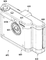
図1にて、装置本体A001においては、カメラ部A100の背面側にプリンタ部(記録装置部)B100が一体的に組み込まれている。プリンタ部B100は、図2のメディアパックC100から供給されるインクとプリント媒体を用いて画像を記録する。C100はB100に対して、図1中、左側の図示されないスロットに挿入され、必要に応じてプリントされたプリント出力物はA109の用紙排出口から排出される。 In FIG. 1, in the apparatus main body A001, a printer section (recording apparatus section) B100 is integrally incorporated on the back side of the camera section A100. The printer unit B100 records an image using ink and a print medium supplied from the media pack C100 in FIG. C100 is inserted into a slot (not shown) on the left side in FIG. 1 with respect to B100, and a printed output printed as necessary is discharged from a paper discharge port of A109.
プリンタ部B100によって記録を行う場合には、カメラ部A100のレンズA101が下側になるように置いた姿勢とする。この記録姿勢において、プリンタ部B100における後述の記録ヘッドB120は、インクを下向きに吐出する姿勢となる。記録姿勢は、カメラ部A100による撮影状態の姿勢と同様の姿勢とすることも可能であり、上記の記録姿勢に限られることはない。記録動作の安定性の面からは、上記のインクを下向きに吐出する記録姿勢が好ましい。 When recording is performed by the printer unit B100, the posture is set so that the lens A101 of the camera unit A100 is on the lower side. In this recording posture, a later-described recording head B120 in the printer unit B100 is in a posture for ejecting ink downward. The recording posture can be the same as the posture in the shooting state by the camera unit A100, and is not limited to the above recording posture. From the viewpoint of the stability of the recording operation, a recording posture in which the above ink is discharged downward is preferable.
以下においては、本例の装置の機械的な基本構成を(1)「カメラ部」、(2)「メディアパック」、(3)「プリンタ部」、(4)「電気制御系」とに分けて説明する。 In the following, the mechanical basic configuration of the apparatus of this example is divided into (1) “camera unit”, (2) “media pack”, (3) “printer unit”, and (4) “electric control system”. I will explain.
(1)「カメラ部」
カメラ部A100は、基本的には、一般的なデジタルカメラを構成するものであり、後述するプリンタ部B100と共に装置本体A001に一体的に組み合わせられることによって、図1のような外観のプリンタ内蔵のデジタルカメラを構成する。図1において、A101はレンズ、A102はファインダー、A102aはファインダー窓、A103はストロボ、A104はレリーズボタン、レンズに対して本体裏側には図示しない液晶表示部(外部表示部)がある。カメラ部A100は、CCDを用いて撮像したデータの処理、メモリカード(CFカード等)への画像の記憶、画像の表示、プリンタ部B100等との間の各種データの授受をする。A109は、撮影された画像を後述のプリント媒体に記録した場合に、画像が記録されたプリント媒体が排出される排出部である。なおカメラ部A100およびプリンタ部B100の電源としてはここでは図示しないが本体内に収納された単3乾電池を用いている。
(1) "Camera part"
The camera unit A100 basically constitutes a general digital camera. When the camera unit A100 is integrally combined with the apparatus main body A001 together with a printer unit B100 described later, the camera unit A100 has a built-in printer with an appearance as shown in FIG. Configure a digital camera. In FIG. 1, A101 is a lens, A102 is a finder, A102a is a finder window, A103 is a strobe, A104 is a release button, and there is a liquid crystal display unit (external display unit) (not shown) on the back side of the main body with respect to the lens. The camera unit A100 processes data captured using a CCD, stores images on a memory card (CF card or the like), displays images, and exchanges various data with the printer unit B100 or the like. A 109 is a discharge unit that discharges the print medium on which the image is recorded when the photographed image is recorded on a print medium described later. As the power source for the camera unit A100 and the printer unit B100, although not shown here, AA batteries stored in the main body are used.
(2)「メディアパック」
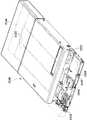
図2のメディアパックC100は、装置本体A001に対して着脱可能であり、本例の場合は、装置本体A001の左側のスロット(図示せず)に差し込まれることによって、装置本体A001に装着される。挿入部のスロットはメディアパックC100が装着されていないときは閉じられており、それが装着されるときに開かれる。図2は、メディアパックC100の外装を外した状態を示す。
(2) “Media Pack”
The media pack C100 of FIG. 2 is detachable from the apparatus main body A001. In this example, the media pack C100 is attached to the apparatus main body A001 by being inserted into a slot (not shown) on the left side of the apparatus main body A001. . The slot of the insertion portion is closed when the media pack C100 is not attached, and is opened when the media pack C100 is attached. FIG. 2 shows a state in which the exterior of the media pack C100 is removed.
パック本体C101には、前述のメインタンクに相当するインクパックC103(ここではインク袋)とプリント媒体C104(ここではインクジェット記録用紙)が収容されている。図2において、インクパックC103は、プリント媒体C104の下方に収容される。本例の場合、インクパックC103は、Y(イエロー),M(マゼンタ),C(シアン)のインクを個別に収容するように3つ備えられており、またプリント媒体C104は20枚重ねて収容されている。それらのインクとプリント媒体C104は、画像の記録に最適な組合せのものが選択された上で、同じメディアパックC100内に収容されている。 The pack body C101 accommodates an ink pack C103 (here, an ink bag) corresponding to the above-described main tank and a print medium C104 (here, inkjet recording paper). In FIG. 2, the ink pack C103 is stored below the print medium C104. In this example, the ink pack C103 is provided with three Y (yellow), M (magenta), and C (cyan) inks, and 20 print media C104 are stacked. Has been. The ink and the print medium C104 are stored in the same media pack C100 after selecting an optimal combination for image recording.
したがって、インクとプリント媒体の組合せが異なる種々のメディアパック(例えば、超高画質用、ノーマル画質用、シール用、分割シール用等のメディアパック)を用意しておいて、記録すべき画像の種類、および画像が形成されるプリント媒体の用途などに応じて、それらのメディアパックを選択的に装置本体A001に装着することにより、最適な組合せのインクとプリント媒体を用いて、目的に応じた画像を確実に記録することができる。ここで、メディアパックC100には図示しないEEPROM(識別IC)が備えられており、そのEEPROMには、メディアパックが収容しているインクとプリント媒体の種類や残量などの識別データが記憶される。 Therefore, various media packs with different combinations of ink and print media (for example, media packs for ultra-high image quality, normal image quality, seal, divided seal, etc.) are prepared and the types of images to be recorded Depending on the use of the print medium on which the image is formed, the media pack is selectively mounted on the apparatus main body A001, so that an image corresponding to the purpose can be obtained using an optimal combination of ink and print medium. Can be recorded reliably. Here, the media pack C100 is provided with an unillustrated EEPROM (identification IC), and the EEPROM stores identification data such as the type and remaining amount of ink and print medium contained in the media pack. .
メディアパックC100のプリンタ部への装着は後述するが(図3参照:プリンタ部B100に対して矢印Cの方向から装着される)、このときインクパックC103は、Y,M,Cのインクのそれぞれに対応する3つのジョイントC105を通して、後述するプリンタ部のインク供給系に接続される。一方、プリント媒体C104は、図示しない分離機構によって一枚ずつ分離されてから、本体内の給紙ローラによって矢印C方向に送り出される。 Although mounting of the media pack C100 to the printer unit will be described later (see FIG. 3: mounting from the direction of the arrow C to the printer unit B100), the ink pack C103 at this time uses the Y, M, and C inks, respectively. Are connected to an ink supply system of a printer unit, which will be described later, through three joints C105. On the other hand, the print media C104 are separated one by one by a separation mechanism (not shown) and then fed out in the direction of arrow C by a paper feed roller in the main body.
また、パック本体C101には、後述するプリンタ部の記録ヘッドをワイプするためのワイパーC106と、プリンタ部から排出された廃インクを吸収するためのインク吸収体C107が備えられている。 Further, the pack body C101 is provided with a wiper C106 for wiping a recording head of the printer unit, which will be described later, and an ink absorber C107 for absorbing waste ink discharged from the printer unit.
(3)「プリンタ部」
図3は本例のプリンタ部B100で、インクジェット記録ヘッドを用いるシリアルタイプの記録装置である。このプリンタ部B100については、(3)−1「プリント動作部」、(3)−2「インク供給回復系」に分けて説明する。
(3) “Printer”
FIG. 3 shows a printer unit B100 of this example, which is a serial type recording apparatus using an ink jet recording head. The printer unit B100 will be described separately in (3) -1 “print operation unit” and (3) -2 “ink supply recovery system”.
(3)−1「プリント動作部」
図3は、プリンタ部B100全体の斜視図で外装を取り外した図である。
(3) -1 “Print Operation Unit”
FIG. 3 is a perspective view of the entire printer unit B100 with the exterior removed.
プリンタ部B100の本体には、図3の矢印C方向からメディアパックC100が挿入されているとする。メディアパックC100から矢印C方向に送り出されたプリント媒体C104は、プリント媒体搬送系におけるLFローラB101とLFピンチローラB102との間に挟まれつつ、プラテンB103上にて矢印Bの副走査方向に搬送される。B104は、ガイド軸B105とリードスクリューB106に沿って矢印Aの主走査方向に往復移動されるキャリッジである。 It is assumed that the media pack C100 is inserted into the main body of the printer unit B100 from the direction of arrow C in FIG. The print medium C104 sent out from the media pack C100 in the direction of arrow C is conveyed in the sub-scanning direction of arrow B on the platen B103 while being sandwiched between the LF roller B101 and the LF pinch roller B102 in the print medium conveyance system. Is done. B104 is a carriage that reciprocates in the main scanning direction indicated by the arrow A along the guide shaft B105 and the lead screw B106.
キャリッジB104のリードスクリューB106に対する軸受けの内側には突出するスクリューピンがバネによって取り付けられている。そして、リードスクリューB106の外周部に形成された螺旋溝に対して、スクリューピンの先端がはまり合うことによって、リードスクリューB106の回転がキャリッジB104の往復移動に変換される。 A projecting screw pin is attached by a spring to the inside of the bearing for the lead screw B106 of the carriage B104. Then, the tip of the screw pin fits into the spiral groove formed on the outer peripheral portion of the lead screw B106, whereby the rotation of the lead screw B106 is converted into the reciprocating movement of the carriage B104.
また、キャリッジB104には、後述するがY,M,Cのインクを吐出可能なインクジェット記録ヘッドB120(図4参照)と、その記録ヘッドB120に供給されるインクを収容するサブタンクが搭載されている。記録ヘッドB120には、矢印Aの主走査方向と交差する方向に沿って並ぶ複数のインク吐出口B121(図4参照)が形成されている。インク吐出口B121は、サブタンクから供給されたインクを吐出可能な複数のノズルにて構成される。インクを吐出させるためのエネルギーの発生手段としては、ノズル毎に備えた電気熱変換体を用いることができる。その電気熱変換体は、発熱駆動されることによってノズル内のインク中に気泡を発生させ、その発泡エネルギーによってインク吐出口B121からインク滴を吐出させる。 The carriage B104 is mounted with an inkjet recording head B120 (see FIG. 4) capable of ejecting Y, M, and C inks, as will be described later, and a sub-tank that accommodates ink supplied to the recording head B120. . The recording head B120 is formed with a plurality of ink ejection ports B121 (see FIG. 4) arranged along the direction intersecting with the main scanning direction of the arrow A. The ink discharge port B121 includes a plurality of nozzles that can discharge ink supplied from the sub tank. As an energy generating means for ejecting ink, an electrothermal converter provided for each nozzle can be used. The electrothermal converter is driven to generate heat, thereby generating bubbles in the ink in the nozzle, and ejecting ink droplets from the ink ejection port B121 by the foaming energy.
サブタンクは、メディアパックC100に収容されているインクパック(メインタンク)C103よりも小容量であり、少なくともプリント媒体C104の1枚分の画像記録に必要な量のインクを収容する大きさとなっている。サブタンクにおいて、Y,M,Cのインク毎のインク収容部分には、それぞれ後述するインク供給部と負圧導入部が形成されており、それらのインク供給部は対応する3つの中空のニードルB122(図4参照)に個別に接続され得るように構成され、また、それらの負圧導入部は共通のエアー吸引口B123(図4参照)に接続され得るように構成されている。サブタンクには後述するように、キャリッジB104がホームポジションに移動したときに、メディアパックC100のインクパック(メインタンク)C103からインクが補給されるようになっている。 The sub tank has a smaller capacity than the ink pack (main tank) C103 accommodated in the media pack C100, and is sized to accommodate at least the amount of ink necessary for image recording of one print medium C104. . In the sub tank, an ink supply portion and a negative pressure introduction portion, which will be described later, are formed in the ink storage portion for each of the Y, M, and C inks, and these ink supply portions correspond to the corresponding three hollow needles B122 ( 4), and the negative pressure introducing portions are configured to be connected to a common air suction port B123 (see FIG. 4). As will be described later, the sub tank is supplied with ink from the ink pack (main tank) C103 of the media pack C100 when the carriage B104 moves to the home position.
キャリッジB104の移動位置は、キャリッジB104側のエンコーダセンサB131と、プリンタ部B100の本体側のリニアスケールB132とによって検出される。また、キャリッジB104がホームポジションに移動したことは、プリンタ部B100の本体側のHPセンサーによって検出される。 The movement position of the carriage B104 is detected by an encoder sensor B131 on the carriage B104 side and a linear scale B132 on the main body side of the printer unit B100. Further, the movement of the carriage B104 to the home position is detected by the HP sensor on the main body side of the printer unit B100.
図示しない調整機構により、キャリッジB104の高さ方向の位置が調整されて、記録ヘッドB120と、プラテンB103上のプリント媒体C104との間の距離(「紙間距離」ともいう)が調整される。また、リードスクリューB106は、スクリューギア、アイドラギア、およびモータギアを介して、キャリッジモータM001によって回転駆動される。また記録ヘッドB120はフレキシブルケーブルを通じて本体基板に接続される。 The position in the height direction of the carriage B104 is adjusted by an adjustment mechanism (not shown), and the distance between the recording head B120 and the print medium C104 on the platen B103 (also referred to as “inter-paper distance”) is adjusted. The lead screw B106 is rotationally driven by a carriage motor M001 via a screw gear, an idler gear, and a motor gear. The recording head B120 is connected to the main body substrate through a flexible cable.
記録ヘッドB120は、キャリッジB104と共に矢印Aの主走査方向に移動しつつ、画像信号に応じてインク吐出口B121からインクを吐出することによって、プラテンB103上のプリント媒体に1行分の画像を記録する。このような記録ヘッドB120による1行分の記録動作と、プリント媒体搬送系による矢印Bの副走査方向へのプリント媒体の所定量の搬送動作とを繰り返すことによって、プリント媒体上に順次画像を記録する。 The recording head B120 records an image for one line on the print medium on the platen B103 by ejecting ink from the ink ejection port B121 according to an image signal while moving in the main scanning direction of the arrow A together with the carriage B104. To do. By repeating such a recording operation for one line by the recording head B120 and a conveying operation for a predetermined amount of the printing medium in the sub-scanning direction of the arrow B by the printing medium conveying system, images are sequentially recorded on the printing medium. To do.
(3)−2「インク供給回復系」
図4に、インク供給回復システムを説明する概念的構成図を示す。
(3) -2 “Ink supply recovery system”
FIG. 4 is a conceptual configuration diagram illustrating the ink supply recovery system.
プリンタ部に装着されたメディアパックC100のジョイントC105は、ホームポジションに移動したキャリッジB104側のニードルB122の下に位置する。プリンタ部の本体には、ジョイントC105の下方に位置するジョイントフォーク(図示せず)が備えられており、そのジョイントフォークがジョイントC105を上に動かすことにより、ジョイントC105がニードルB122に接続される。これにより、メディアパックC100側のインクパックC103と、キャリッジB104側のサブタンクB400との間でインク供給路が形成される。 The joint C105 of the media pack C100 attached to the printer unit is positioned below the needle B122 on the carriage B104 side that has moved to the home position. The main body of the printer unit is provided with a joint fork (not shown) positioned below the joint C105, and the joint fork moves the joint C105 upward to connect the joint C105 to the needle B122. Accordingly, an ink supply path is formed between the ink pack C103 on the media pack C100 side and the sub tank B400 on the carriage B104 side.
また、プリンタ部の本体には、ホームポジションに移動したキャリッジB104のエアー吸引口B123に接続するための負圧供給ジョイントB302が備えられている。この負圧供給ジョイントB302は、負圧供給チューブB303を介して、負圧発生源としてのポンプのシリンダポンプB304に接続されている。負圧供給ジョイントB302は、図示しないジョイントリフターによって上に動かされることにより、キャリッジB104側のエアー吸引口B123に接続される。これにより、キャリッジB104側のサブタンクの負圧導入部と、シリンダポンプB304との間の負圧導入路が形成される。 Further, the main body of the printer unit is provided with a negative pressure supply joint B302 for connecting to the air suction port B123 of the carriage B104 moved to the home position. The negative pressure supply joint B302 is connected to a cylinder pump B304 of a pump as a negative pressure generation source via a negative pressure supply tube B303. The negative pressure supply joint B302 is connected to the air suction port B123 on the carriage B104 side by being moved upward by a joint lifter (not shown). As a result, a negative pressure introducing path is formed between the negative pressure introducing portion of the sub tank on the carriage B104 side and the cylinder pump B304.
ジョイントリフターは、ジョイントモータM003の駆動力によって、負圧供給ジョイントB302と共にジョイントフォーク(及びそれによって上下動するC105)を同時に上下動させる。すなわち、インク供給路と負圧導入路の形成は同時に行われるようになっている。 The joint lifter simultaneously moves the joint fork (and C105 that moves up and down thereby) together with the negative pressure supply joint B302 by the driving force of the joint motor M003. That is, the ink supply path and the negative pressure introduction path are formed simultaneously.
サブタンクの負圧導入部には、空気の通過を許容し、かつインクの通過を阻止する気液分離部材B402が備えられている。気液分離部材は、負圧導入路を通して吸引されるサブタンク内の空気の通過を許容し、これによりメディアパックC100からサブタンクにインクが補給される。そして、サブタンク内のインクが気液分離部材に達するまで、インクが充分に補給されたときに、その気液分離部材がインクの通過を阻止することにより、インクの補給が自動的に停止する。気液分離部材は、サブタンクのインク毎のインク収容部分におけるインク供給部に備えられており、それらのインク収容部分毎に、インクの補給を自動的に停止させる。 The negative pressure introducing portion of the sub tank is provided with a gas-liquid separation member B402 that allows passage of air and prevents passage of ink. The gas-liquid separation member allows the passage of air in the sub tank sucked through the negative pressure introduction path, whereby ink is supplied from the media pack C100 to the sub tank. Then, when the ink is sufficiently replenished until the ink in the sub tank reaches the gas-liquid separation member, the gas-liquid separation member prevents the ink from passing, whereby the ink replenishment is automatically stopped. The gas-liquid separation member is provided in an ink supply portion in an ink storage portion for each ink in the sub tank, and automatically stops ink supply for each ink storage portion.
また、プリンタ部の本体には、ホームポジションに移動したキャリッジB104側の記録ヘッドB120に対して、キャッピングが可能な吸引キャップB310が備えられている。吸引キャップB310は、その内部に、吸引チューブB311を通してシリンダポンプB304から負圧が導入されることによって、記録ヘッドB120のインク吐出口B121からインクを吸引排出(吸引回復処理)させることができる。また、記録ヘッドB120は、必要に応じて、画像の記録に寄与しないインクを吸引キャップB310内に吐出させる(予備吐出処理)。吸引キャップB310内のインクは、シリンダポンプB304から、廃液チューブB312と廃液ジョイントB313を通して、メディアパックC100内のインク吸収体C107に排出される。 Further, the main body of the printer unit is provided with a suction cap B310 capable of capping the recording head B120 on the carriage B104 side moved to the home position. The suction cap B310 can suck and discharge ink (suction recovery process) from the ink discharge port B121 of the recording head B120 by introducing a negative pressure from the cylinder pump B304 through the suction tube B311 into the suction cap B310. Moreover, the recording head B120 discharges ink that does not contribute to image recording into the suction cap B310 as necessary (preliminary discharge processing). The ink in the suction cap B310 is discharged from the cylinder pump B304 to the ink absorber C107 in the media pack C100 through the waste liquid tube B312 and the waste liquid joint B313.
シリンダポンプB304は、ポンプモータM003により往復駆動される。ポンプモータM003は、前述したジョイントリフターを上下動させるための駆動源としても機能する。またワイパーリフターを上下動するための駆動源としても機能する。ワイパーリフターとは、プリンタ部B100に装着されたメディアパックC100のワイパーC106を上に動かすことによって、そのワイパーC106を記録ヘッドB120のワイピングが可能な位置に移動させるものである。なおB303、B311、B312等のチューブに対しては必要に応じて、図示しない弁が設けられていて、ポンプモータM003の各動作時には、それらの弁を開閉し、各色ごとの吸引や、一括吸引等の所望の動作を行い、昇降動作時には他の吸引や排出動作に影響を与えないようになっている。 The cylinder pump B304 is driven to reciprocate by a pump motor M003. The pump motor M003 also functions as a drive source for moving the above-described joint lifter up and down. It also functions as a drive source for moving the wiper lifter up and down. The wiper lifter moves the wiper C106 to a position where the recording head B120 can be wiped by moving the wiper C106 of the media pack C100 attached to the printer unit B100 upward. In addition, valves such as B303, B311, and B312 are provided with valves (not shown) as necessary, and when the pump motor M003 is operated, these valves are opened and closed so that suction for each color or batch suction is performed. The desired operation such as the above is performed, and other suction and discharge operations are not affected during the lifting operation.
シリンダポンプB304は、ポンプの動作位置がホームポジションにあることを検出するポンプHPセンサ(図示せず)により、プリンタのスタンバイ状態ではポンプのHP側に待機している。 The cylinder pump B304 stands by on the HP side of the pump in a standby state of the printer by a pump HP sensor (not shown) that detects that the operating position of the pump is at the home position.
ここでは、カメラ部A100とプリンタ部B100が一体となったプリンタ内蔵カメラとして説明を行なっている。しかし、本発明では、カメラ部A100とプリンタ部B100を分離した別々の装置とし、それらをインターフェースにより接続した構成においても同様に構成して、同様の機能を実現することが可能である。 Here, a description is given of a camera with a built-in printer in which the camera unit A100 and the printer unit B100 are integrated. However, according to the present invention, the camera unit A100 and the printer unit B100 can be separated from each other, and the same configuration can be realized in a configuration in which they are connected by an interface.
(インク供給回復系の詳細な説明)
以上が一般的なピットイン供給方式を用いたインク供給回復系の概略の説明であるが、以下にインク供給回復系について詳細に説明する。インク供給回復システムの概念的構成図は図4であり上述したものと同じである。上述した部分と重複する個所もあるが、図2と図4を用いて一連の動作を説明する。
(Detailed description of ink supply recovery system)
The above is a schematic description of an ink supply recovery system using a general pit-in supply system. The ink supply recovery system will be described in detail below. A conceptual configuration diagram of the ink supply recovery system is shown in FIG. 4 and is the same as described above. Although there are portions that overlap the above-described portions, a series of operations will be described with reference to FIGS.
図2において、メディアパックC100内には、Y(イエロー),M(マゼンタ),C(シアン)の3色のインクが充填されている3つのインクパック(メインタンク)C103が収容されている。これら3つのインクパックC103は3つのインク供給路C200を介して3つのジョイント(インクジョイント)C105に接続されている。 In FIG. 2, the media pack C100 contains three ink packs (main tanks) C103 filled with inks of three colors Y (yellow), M (magenta), and C (cyan). These three ink packs C103 are connected to three joints (ink joints) C105 via three ink supply paths C200.
図4においてキャリッジB104には、Y,M,Cのインクを別々に貯留するサブタンク(キャリッジタンクともいう)B400と、各キャリッジタンクB400から供給されたインクを吐出する3グループ分(Y,M,C)の複数のインク吐出口(ノズル)B121を有する記録ヘッドB120が搭載されている。 In FIG. 4, the carriage B104 has a sub-tank (also referred to as a carriage tank) B400 that stores Y, M, and C inks separately, and three groups (Y, M, and C) that discharge ink supplied from each carriage tank B400. A recording head B120 having a plurality of ink discharge ports (nozzles) B121 is mounted.
サブタンクB400の各インクの収容部(インク供給部)には、発泡体または繊維質体等を含む多孔質体、例えばポリプロピレン繊維などのインクを吸収保持するインク吸収体(スポンジ)B401がほぼ充塞されている。また、サブタンクB400の各インクの収容部(インク供給部)には、図4に示したように、下方に突出された貫通孔を有するニードル(インク取入部)B122が夫々設けられている。これら3つのニードルB122は、キャリッジB104がホームポジションに移動したときに、メディアパックC100の3つのゴムジョイントC105に夫々接続可能となる。ニードルB122の先には横穴が空いていてインク供給が可能となっている。先端は針状にクローズされている。 Each ink container (ink supply unit) of the sub-tank B400 is almost filled with a porous body including foam or a fibrous body, for example, an ink absorber (sponge) B401 that absorbs and holds ink such as polypropylene fiber. ing. Further, as shown in FIG. 4, needles (ink intake portions) B122 each having a through-hole protruding downward are provided in each ink storage portion (ink supply portion) of the sub tank B400. These three needles B122 can be connected to the three rubber joints C105 of the media pack C100 when the carriage B104 moves to the home position. A horizontal hole is formed at the tip of the needle B122 so that ink can be supplied. The tip is closed like a needle.
サブタンクB400の各インク供給部の上方には負圧導入部B410が形成されている。これら負圧導入部B410には、撥水、撥油処理が施され、空気の通過を許容しかつインクの通過を阻止する気液分離部材としての多孔質膜(インク満タン弁)B402が夫々備えられている。この多孔質膜B402によれば、インクの通過が阻止されるので、サブタンクB400内のインクの液面が多孔質膜B402まで達したとき、インクの補給は自動的に停止される。撥水、撥油処理が施されていないと、インクに対して濡れやすく、特に耐久後においては濡れ易い個所の気液分離膜の細孔にインクが入り込んでそのままになってしまうために、実質的に気液分離の効果を果たさないため、エアーの導入効率が下がり、従ってインク供給能力も下がってしまうことになる。 A negative pressure introduction part B410 is formed above each ink supply part of the sub tank B400. These negative pressure introduction portions B410 are subjected to water and oil repellency treatments, and porous membranes (ink full valves) B402 as gas-liquid separating members that allow air to pass and prevent ink from passing, respectively. Is provided. According to the porous film B402, the ink is prevented from passing, so that the ink supply is automatically stopped when the ink level in the sub tank B400 reaches the porous film B402. If water and oil repellency treatments are not applied, the ink will easily get wet with the ink, and in particular after the endurance, the ink will enter the pores of the gas-liquid separation membrane where it easily gets wet. Since the gas-liquid separation effect is not achieved, the air introduction efficiency is lowered, and the ink supply capability is also lowered.
サブタンクB400の各負圧導入部B410は、前述したように、キャリッジB104の下面側に形成された3色共通のエアー吸引口B123に連通されている。このエアー吸引口B123は、キャリッジB104がホームポジションに移動したときに、プリンタ部B100の本体側に設けられた負圧供給ジョイントB302と連結可能になり、負圧供給ジョイントB302、負圧供給チューブB303を介して、ポンプユニットB315のシリンダポンプB304の一方のシリンダ室と接続可能となる。 As described above, each negative pressure introducing portion B410 of the sub tank B400 communicates with the air suction port B123 common to the three colors formed on the lower surface side of the carriage B104. When the carriage B104 moves to the home position, the air suction port B123 can be connected to a negative pressure supply joint B302 provided on the main body side of the printer unit B100, and the negative pressure supply joint B302 and the negative pressure supply tube B303 are connected. It becomes possible to connect with one cylinder chamber of cylinder pump B304 of pump unit B315 via.
プリンタ部B100側には、キャリッジB104がホームポジションに移動したときに、Y,M,Cの3グループ分の複数のインク吐出口(ノズル)B121が形成された記録ヘッドB120のフェース面(インク吐出口形成面)B403をキャッピングするための吸引キャップB310が備えられている。吸引キャップB310には、大気連通口B404が形成されている。この大気連通口B404は大気連通弁(図示せず)によって開閉可能である。 On the printer unit B100 side, when the carriage B104 moves to the home position, the face surface (ink discharge) of the recording head B120 in which a plurality of ink discharge ports (nozzles) B121 for three groups of Y, M, and C are formed. A suction cap B310 for capping the outlet forming surface B403 is provided. An air communication port B404 is formed in the suction cap B310. This atmospheric communication port B404 can be opened and closed by an atmospheric communication valve (not shown).
吸引キャップB310は、吸引チューブB311を通してシリンダポンプB304の他方のシリンダ室に接続されている。シリンダポンプB304は、負圧供給チューブB303、吸引チューブB311および廃液チューブB312とそれぞれ接続される3つのポートを有している。 The suction cap B310 is connected to the other cylinder chamber of the cylinder pump B304 through the suction tube B311. The cylinder pump B304 has three ports respectively connected to the negative pressure supply tube B303, the suction tube B311 and the waste liquid tube B312.
図4のキャリッジB104において、B124はニードルカバーであり、ニードルB122とジョイントC105とが連結していないときは、スプリングの力によってニードルB122の横穴をゴミの付着混入から保護する位置に移動している。またニードルカバーB124は、ニードルB122とジョイントC105とが連結するときは、スプリングの力に抗して同図中の上方に押されてニードルB122の保護を解く。 In the carriage B104 of FIG. 4, B124 is a needle cover, and when the needle B122 and the joint C105 are not connected, it is moved to a position that protects the lateral hole of the needle B122 from adhering to dust by the force of the spring. . Further, when the needle B122 and the joint C105 are connected, the needle cover B124 is pushed upward in the drawing against the force of the spring to release the protection of the needle B122.
ところで、図4に示したように、サブタンクB400の内面に設けられている気体透過部材B402とインク吸収体B401とは、空間B412によって隔てられて互いに接触していないように構成することが好ましい。気液分離膜B402は、長期間インクに接した場合、その気液分離性能が低下する可能性がある。しかし、本実施形態においては、気液分離膜B402とインク吸収体B401との間に、空間B412を設けて気体透過部材B402とインク吸収体B401とが直接接触することを避けることにより、インクの補給時以外のときは、気液分離膜B402にインクが接しない。したがって、気液分離膜B402の機能の低下を防止することができる。また、空間B412の内壁面(例えばB414で示す面)は、適切な表面処理(例えば撥水処理)によってインクの付着が極力抑えられることが好ましい。 Incidentally, as shown in FIG. 4, it is preferable that the gas permeable member B402 and the ink absorber B401 provided on the inner surface of the sub tank B400 are separated from each other by a space B412 and are not in contact with each other. When the gas-liquid separation membrane B402 is in contact with ink for a long period of time, the gas-liquid separation performance may be lowered. However, in this embodiment, a space B412 is provided between the gas-liquid separation membrane B402 and the ink absorber B401 to avoid direct contact between the gas permeable member B402 and the ink absorber B401. At times other than replenishment, the ink does not contact the gas-liquid separation membrane B402. Therefore, it is possible to prevent the function of the gas-liquid separation membrane B402 from being lowered. In addition, it is preferable that the inner wall surface of the space B412 (for example, a surface indicated by B414) can suppress ink adhesion as much as possible by appropriate surface treatment (for example, water repellent treatment).
メインタンクC103からサブタンクB400にインクを供給する場合は、前述のジョイントリフタ(またはジョイントフォーク)により、ゴムジョイントC105とニードルB122、負圧供給ジョイントB302とエアー吸引口B123とをそれぞれ接合し、シリンダポンプB304によって負圧導入部B410および気液分離膜B402を通してサブタンクB400中の空気を吸引することによってメインタンクからサブタンクにインクを供給する。 When ink is supplied from the main tank C103 to the subtank B400, the rubber joint C105 and the needle B122, the negative pressure supply joint B302, and the air suction port B123 are joined by the joint lifter (or joint fork), respectively, and the cylinder pump Ink is supplied from the main tank to the sub tank by sucking the air in the sub tank B400 through the negative pressure introducing part B410 and the gas-liquid separation membrane B402 by B304.
サブタンク内へのインク供給後、ゴムジョイントC105とニードルB122、負圧供給ジョイントB302とエアー吸引口B123とをそれぞれ分離させ、必要に応じて吸引キャップB310からシリンダポンプB304によってサブタンク内のインクを吸引する。ここでは少なくともインク針内に存在するインク量以上程度は吸引することが好ましい。あるいは別な観点から、記録ヘッドB120にインクを通し、ノズル近傍に存在する(もしくは混入する可能性のある)泡を取り除く程度の吸引を行った後に、記録動作を行う。 After supplying the ink into the sub tank, the rubber joint C105 and the needle B122, the negative pressure supply joint B302 and the air suction port B123 are separated from each other, and the ink in the sub tank is sucked from the suction cap B310 by the cylinder pump B304 as necessary. . Here, it is preferable to suck at least about the amount of ink present in the ink needle. Alternatively, from another viewpoint, the recording operation is performed after the ink is passed through the recording head B120 and suction is performed to remove bubbles existing in the vicinity of the nozzle (or possibly mixed in).
4「電気制御系」
次に、本装置の電気制御系の構成について図7を参照しながら説明する。
4 "Electric control system"
Next, the configuration of the electric control system of this apparatus will be described with reference to FIG.
図7に本装置の電気構成のブロック図を示す。図7において、500はMPU部及びプリンターコントロール部を一体化したASICを示している。504は装置の全体を制御するプログラムが収められたフラッシュROM、506はASICの作業エリア及び記録画像のバッファーとして使用されるDRAMを示している。509はEEPROMを示し、このEEPROMは書き換え可能なROMであり電源が供給されなくても内容が消えないものである。EEPROM509には、電源ONの時にユーザーが行った設定情報や、使用インク量、サブタンクに残存しているインク量等が書き込まれている。ASICはまた、ヒートパルス生成のコントローラを含み、記録ヘッドB120に対して記録ヘッドの制御信号を生成し送信する。またASICは、キャリッジや紙送りの制御、他電源やLEDや各種センサーとのI/Oや、カメラ側とのデータの送受信、またはコンピューターとのデータの送受信を行う。
FIG. 7 shows a block diagram of the electrical configuration of the present apparatus. In FIG. 7,
502はキャリッジB104の駆動を行うためのキャリッジモータードライバーを示し、503は紙送りローラを駆動するための紙送りモータドライバーを示している。キャリッジモータードライバー502及び紙送りモータドライバー503はASICから出力される制御信号によりモータのコントロールをおこなう。
本装置のカメラ部及びプリンタ部は電池116で駆動する。また装置内には別の電源115を持ち、それはカメラの電源Off中の日付情報保持や、測定等の用途に用いられる。106は本体の電源を投入する電源スイッチを示し、符号107はエラー解除スイッチ、110はパワーランプ、109はエラーランプを示している。
The camera unit and printer unit of this apparatus are driven by a
118はインターフェースコネクターを示し、例えばホストコンピューターなどの外部との信号通信を行う。インターフェースコネクター118は有線でホストコンピューターに接続される。119は内蔵インターフェースで、ここではカメラ一体型プリンタのカメラ部とのデータの送受信を行う。
HPセンサー26はフォトインタラプタタイプのセンサーであり、キャリアB104の位置を検出する。またペーパーセンサー25、排紙センサー17は接点式のセンサーで記録装置内の記録用紙の有無を検出する。
The
なお、本発明は、インクパック(メインタンク)C103とプリント媒体C104とが収容されているメディアパックC100を用いる形態に限定されるものではない。つまり、インクパック(メインタンク)とプリント媒体とは同じ容器に収容されている必要性はなく、例えば、一般のプリンタのように、プリント媒体は装置外部から挿入できるように構成し、メインタンクはそれ単独で装置に装着できるように構成してもよい。なお、サブタンクは少なくとも記録媒体1枚分の画像記録に必要な量のインクを収容できる大きさとなっていればよい。 Note that the present invention is not limited to the form using the media pack C100 in which the ink pack (main tank) C103 and the print medium C104 are accommodated. In other words, the ink pack (main tank) and the print medium do not need to be stored in the same container. For example, the print medium can be inserted from the outside of the apparatus like a general printer. You may comprise so that it can mount | wear with an apparatus independently. Note that the subtank only needs to be large enough to accommodate an amount of ink necessary for image recording for at least one recording medium.
(本発明の特徴的部分)
本発明では、サブタンク内の残存インクの少なくとも一部を排出するインク排出処理を、次回の記録動作(印字)のためのピットインインク供給(第2のピットインインク供給ともいう)の前に行うことを特徴事項としている。以下、本発明の特徴事項を第1〜第24実施形態にて説明する。
(Characteristic part of the present invention)
In the present invention, the ink discharging process for discharging at least a part of the remaining ink in the sub tank is performed before the pit-in ink supply (also referred to as the second pit-in ink supply) for the next recording operation (printing). It is a feature item. The features of the present invention will be described below in the first to twenty-fourth embodiments.
第1〜第19の実施形態では上記インク排出処理を記録開始前のタイミングで行なっているが、本明細書において「記録開始前のタイミング」とは、例えば、電源ON(電源投入)をトリガとしたタイミング、あるいは、記録動作を開始するための記録開始信号の受信をトリガとしたタイミング、あるいは電源投入後の最初の記録動作を開始するための初期記録開始信号の受信をトリガとしたタイミングのいずれかである。 In the first to nineteenth embodiments, the ink discharge process is performed at a timing before the start of recording. In this specification, the “timing before the start of recording” is, for example, a power ON (power on) as a trigger. Timing triggered by reception of a recording start signal for starting a recording operation, or timing triggered by reception of an initial recording start signal for starting the first recording operation after power-on It is.
また、本明細書において「放置期間」とは、前回の印字終了から次回の印字開始の間において電源Offが継続している期間、あるいは、前回の電源OFF時から次回の印字開始時(次回の記録動作を開始するための記録開始信号の受信時)までの期間、あるいは、前回の印字終了時から次回の印字開始時までの期間、あるいは前回の回復処理(吸引回復)の終了から次回の印字開始時までの期間のいずれかである。 Further, in this specification, the “leaving period” is a period in which the power is continuously turned off between the end of the previous print and the start of the next print, or the next print start from the previous power off (next time The period from the end of the previous print to the start of the next print, or the end of the previous recovery process (suction recovery) until the next print One of the periods up to the start.
(第1の実施形態)
第1の実施形態は、記録動作で使用するインクをサブタンクへ供給するピットインインク供給(以下、(次回)記録動作のためのピットインインク供給、あるいは(次回)印字時のピットインインク供給という)の前において、サブタンク内の残存インクを排出するインク排出処理を行うことを特徴とする。ここでは、特に、記録ヘッドを吸引キャップと密着させた状態で記録ヘッドからインクを吸引することで、記録ヘッドを介してサブタンク内の残存インクを排出する場合について説明する。この第1の実施形態では、上記インク排出処理を記録開始前のタイミングにて行う。
(First embodiment)
In the first embodiment, before the pit-in ink supply for supplying ink used in the recording operation to the sub-tank (hereinafter referred to as the (next) pit-in ink supply for the recording operation or (next) pit-in ink supply at the time of printing). The ink discharging process for discharging the residual ink in the sub tank is performed. Here, in particular, a case will be described in which the ink remaining in the sub-tank is discharged through the recording head by sucking ink from the recording head while the recording head is in close contact with the suction cap. In the first embodiment, the ink discharge process is performed at a timing before the start of recording.
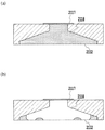
図14は、第1の実施形態を説明するためのサブタンク内のインクの状態を示す模式図である。図14(a)は、記録終了時におけるサブタンク内の残存インクの状態を表している。サブタンクB400にインクが満タンに充填された状態から、記録動作によってb101までインクが減少した様子を表している。 FIG. 14 is a schematic diagram showing the state of ink in the sub tank for explaining the first embodiment. FIG. 14A shows the state of the remaining ink in the sub tank at the end of recording. This shows a state in which the ink is reduced from the state where the sub tank B400 is filled with ink to b101 by the recording operation.
前述したように、サブタンクにはニードルやエアー吸引口といった大気と連通する箇所があるため、長期間低湿度環境に放置された場合には、インク中の水分がサブタンクから水蒸気として蒸発し、b102まで内部インクが濃縮されインク中の色材濃度が上昇することが起こり得る(図14(b))。この状態からピットインインク供給がなされた場合、満タンのb103まで新しいインクが供給されても、比較的多量の残存濃縮インクに対し新供給インクが混合することになるため、その混合インクの濃度は初期のインク濃度よりも高いものになってしまう(図14(c))。そして、この図14(c)の状態のインクで再度記録を行うと、初期濃度(濃縮する前の濃度)のインクで記録を行った場合に比べ、記録濃度が高くなったり、減法混色によるカラー記録時に色調がずれたりする場合がある。つまり、画像の色調が不自然になる、あるいは、複数枚の画像間で色調が異なる、といった濃縮インクによる弊害が発生するのである。 As described above, since there are locations in the sub tank that communicate with the atmosphere such as needles and air suction ports, the water in the ink evaporates from the sub tank as water vapor when left in a low-humidity environment for a long time. It is possible that the internal ink is concentrated and the color material concentration in the ink is increased (FIG. 14B). When pit-in ink is supplied from this state, even if new ink is supplied up to full b103, the newly supplied ink is mixed with a relatively large amount of remaining concentrated ink, so the density of the mixed ink is The ink density becomes higher than the initial ink density (FIG. 14 (c)). When recording is performed again with the ink in the state shown in FIG. 14 (c), the recording density becomes higher or the color due to subtractive color mixing is higher than when recording is performed with ink having an initial density (density before concentration). Color tone may be shifted during recording. That is, the adverse effect of the concentrated ink occurs such that the color tone of the image becomes unnatural or the color tone is different among a plurality of images.
これに対して、本実施形態では、図14(d)に示すように、記録開始前のタイミングにおいて吸引動作によってサブタンク内の残存濃縮インクをb104のレベルまで排出している。もちろん、このレベルは例として表示しているだけであって、どのレベルまで排出を行うかはインクの残量やインク種などによって適宜決められるものであって、本例のみに限られるものではない。なお、色調の改善には、残存濃縮インクをほぼ全量排出することが最も効果的であるが、残存濃縮インクを一部排出するだけでも効果はある。また、残存濃縮インクを一部だけ排出する場合にはインク消費量抑制の点で有利である。 In contrast, in the present embodiment, as shown in FIG. 14D, the remaining concentrated ink in the sub tank is discharged to the level of b104 by the suction operation at the timing before the start of recording. Of course, this level is only displayed as an example, and the level to be discharged is determined as appropriate according to the remaining amount of ink and ink type, and is not limited to this example. . For the improvement of the color tone, it is most effective to discharge almost all of the remaining concentrated ink, but it is also effective to discharge only a part of the remaining concentrated ink. Further, when only a part of the remaining concentrated ink is discharged, it is advantageous in terms of suppressing ink consumption.
図14(d)では残存濃縮インクの量が非常に少なくなっている。従って、この状態からピットインインク供給を行った場合、残存濃縮インクの量に対し供給される新供給インクの量が十分多いため、インク濃度の上昇はほとんど起こらず、正常な記録を行うことが可能となる。 In FIG. 14 (d), the amount of remaining concentrated ink is very small. Therefore, when pit-in ink is supplied from this state, the amount of newly supplied ink supplied is sufficiently large relative to the amount of remaining concentrated ink, so that the ink density hardly increases and normal recording can be performed. It becomes.
以上の述べたように第1の実施形態によれば、記録開始前において、比較的長期間放置されたサブタンク内の残存濃縮インクを少なくとも一部排出した後に、ピットインインク供給にてサブタンク内へ新インクを供給する構成であるため、初期濃度に比較的近い濃度のインクで記録を行うことができ、その結果、色調のズレを軽減できる。また、複数ページ間での濃度差も抑制できる。 As described above, according to the first embodiment, at least a part of the remaining concentrated ink in the sub-tank that has been left for a relatively long period of time before the start of recording is discharged, and then the pit-in ink is supplied to the sub-tank. Since the ink is supplied, recording can be performed with ink having a density that is relatively close to the initial density, and as a result, color shift can be reduced. Moreover, the density difference between a plurality of pages can be suppressed.
(第2の実施形態)
第2の実施形態は、サブタンクの放置期間(例えば、前回の記録動作終了からの経過期間)に基づいて、サブタンク内の残存インクを排出する排出処理を実行するか否かを切り替えることを特徴とする。より具体的には、放置期間が所定期間以上であれば、記録動作のためのピットインインク供給の前に、サブタンク内の残存インクを排出する排出処理を行い、一方、放置期間が所定期間よりも短ければ、サブタンク内の残存インクを排出する排出処理を行わないように制御する。
(Second Embodiment)
The second embodiment is characterized by switching whether or not to execute the discharge process for discharging the remaining ink in the sub tank based on the sub tank leaving period (for example, the elapsed period from the end of the previous recording operation). To do. More specifically, if the leaving period is equal to or longer than the predetermined period, a discharge process for discharging the remaining ink in the sub tank is performed before supplying the pit-in ink for the recording operation, while the leaving period is longer than the predetermined period. If it is shorter, control is performed so as not to perform the discharge process of discharging the remaining ink in the sub tank.
このような排出処理の切り替え制御を行なう理由は概略次の通りである。すなわち、放置期間が比較的短い場合、サブタンク中のインクの蒸発はまだそれ程進行していない。従って、第1の実施形態で述べたような濃度の上昇はあまり起こっておらず、実用上それ程問題ないと考えられる。そういった場合には、記録動作のためのピットインインク供給の前における上記残存インクの排出処理を行わないようにする。これにより、必要以上にインクを消費しないようにすることができる。ある環境下でのサブタンク内のインクの蒸発速度は、放置された期間によって推測することが可能であるので、放置期間を計測(タイムカウント)することにより上記排出処理の切り替え制御を具現化することができる。 The reason why such discharge process switching control is performed is as follows. That is, when the leaving period is relatively short, the evaporation of the ink in the sub tank has not progressed so much. Therefore, the increase in concentration as described in the first embodiment does not occur so much, and it is considered that there is no problem in practical use. In such a case, the remaining ink is not discharged before the pit-in ink is supplied for the recording operation. Thereby, it is possible to prevent the ink from being consumed more than necessary. Since the evaporation rate of the ink in the sub-tank in a certain environment can be estimated from the left period, the discharge process switching control is realized by measuring the left period (time counting). Can do.
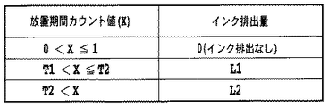
図15に示すフローチャートを参照して第2の実施形態について説明する。まず、プリンタの電源オフ信号によってタイムカウンタXを初期化し、ステップS1501において放置期間のカウントを開始する。このカウンタは所定期間が経過する度毎にXの値を増やしていく構成となっており、例えば、1秒毎にXの値を1ずつ増加させる構成、1分毎にXの値を1ずつ増加させる構成、1時間毎にXの値を1ずつ増加させる構成、あるいは1日毎にXの値を1ずつ増加させる構成等を用いることができる。ステップS1502において電源が投入(ON)されたら、この時点でのXの値を所定の閾値αと比較する(ステップS1503)。 The second embodiment will be described with reference to the flowchart shown in FIG. First, the time counter X is initialized by the printer power-off signal, and in step S1501, counting of the leaving period is started. This counter is configured to increase the value of X every time a predetermined period elapses. For example, the counter is configured to increase the value of X by 1 every second, and the value of X is incremented by 1 every minute. A configuration for increasing the value of X by 1 every hour, a configuration for increasing the value of X by 1 every day, or the like can be used. When the power is turned on (ON) in step S1502, the value of X at this time is compared with a predetermined threshold value α (step S1503).
このステップS1503においてXの値が閾値α未満であれば、サブタンク内のインクはまだ蒸発がさほど進んでいないと判断し、そのままステップS1504をスキップしてステップS1505へ進む。一方、Xの値が閾値α以上であれば、インク濃縮を低減するためにステップS1504に進み、ステップS1504において吸引動作を行いサブタンクからインクを排出する。なお、ここでのインク排出量は上記第1の実施形態と同様で構わない。その後、ステップS1505へ進みカウンタXを初期化する。次に電源OFF信号が来ればステップS1501へ戻り、そのままであれば印字待機状態となる。なお、この印字待機状態において記録開始信号が入力されたら、サブタンクへのピットイン供給を適宜行い、その後記録を開始する。 If the value of X is less than the threshold value α in step S1503, it is determined that the ink in the sub-tank has not progressed so much, and step S1504 is skipped and the process proceeds to step S1505. On the other hand, if the value of X is equal to or greater than the threshold value α, the process proceeds to step S1504 to reduce ink concentration, and in step S1504, a suction operation is performed to discharge ink from the sub tank. The ink discharge amount here may be the same as that in the first embodiment. Thereafter, the process proceeds to step S1505 to initialize the counter X. Next, if a power OFF signal is received, the process returns to step S1501. When a recording start signal is input in this print standby state, pit-in is appropriately supplied to the sub tank, and then recording is started.
このように図15では、電源ON後の最初の記録動作のためのピットインインク供給の前にインク排出処理の実行有無を電源ON時に判断している。しかし、このインク排出処理の実行有無の判断時期は電源ON時に限られるものではなく、記録開始前であればよく、例えば、記録開始信号の受信時でもよい。また、上記図15では、タイムカウント値Xを前回の電源OFFからの経過期間としているが、これには限られず、前回の記録動作終了からの経過期間でもよい。以下で図16を参照しながら、インク排出処理の実行有無の判断時期を記録開始信号の受信時とし、且つタイムカウント値Xを前回の記録動作終了からの経過期間とした場合について説明する。 As described above, in FIG. 15, whether or not the ink discharge process is performed is determined when the power is turned on before supplying the pit-in ink for the first recording operation after the power is turned on. However, the determination timing of whether or not to execute the ink discharge process is not limited to when the power is turned on, and may be before the start of recording, for example, when the recording start signal is received. In FIG. 15, the time count value X is the elapsed period from the previous power-off, but is not limited to this, and may be the elapsed period from the end of the previous recording operation. Hereinafter, a case where the determination timing of whether or not to execute the ink discharge process is set at the time of receiving the recording start signal and the time count value X is set as the elapsed period from the end of the previous recording operation will be described with reference to FIG.
図16のフローチャートについて説明すると、まず、ステップS1601にて記録開始信号を受信すると、ステップS1602にてタイムカウント値Xが所定の閾値α以上であるか否かを判断する。ここで、タイムカウント値Xは、前回の記録動作終了からの経過期間とする。ステップS1602にてXの値がα未満であると判断されたら、インク排出処理(ステップS1603)は行わずにステップS1604へ進む。一方、ステップS1602にてXの値がα以上であると判断されたらステップS1603にてインク排出処理を行い、その後ステップS1604へ進む。なお、このインク排出処理における排出量は上記第1の実施形態と同様で構わない。ステップS1604においてピットインインク供給方式にてサブタンク内へ新インクを供給したら、ステップS1605にて通常の回復動作(吸引動作)を行い、ステップS1606にて記録動作を開始する。 Referring to the flowchart of FIG. 16, when a recording start signal is received in step S1601, it is determined in step S1602 whether or not the time count value X is equal to or greater than a predetermined threshold value α. Here, the time count value X is an elapsed period from the end of the previous recording operation. If it is determined in step S1602 that the value of X is less than α, the process advances to step S1604 without performing the ink discharge process (step S1603). On the other hand, if it is determined in step S1602 that the value of X is greater than or equal to α, ink discharge processing is performed in step S1603, and then the process proceeds to step S1604. The discharge amount in the ink discharge process may be the same as that in the first embodiment. When new ink is supplied into the sub tank by the pit-in ink supply method in step S1604, a normal recovery operation (suction operation) is performed in step S1605, and a recording operation is started in step S1606.
なお、図16のフローチャートは、記録信号の受信の度毎に行う構成であってもよいし、電源ON後の最初の記録開始信号の受信時だけに行なう構成であってもよい。 Note that the flowchart of FIG. 16 may be configured every time a recording signal is received, or may be configured only when the first recording start signal is received after the power is turned on.
以上説明したように第2の実施形態によれば、放置期間が長い場合にはインク濃縮度が高いと推定し、インク排出処理を行ってからピットインインク供給を行い、一方、放置期間が短い場合にはインク濃縮度が低いと推定し、インク排出処理を行なわずにピットインインク供給を行うようにしているので、上記第1の実施形態の効果(色調ズレの軽減、複数ページ間での濃度差の軽減)に加え、インク消費量の低減を図れる。すなわち、本実施形態によれば、インク排出量を抑制しつつも、インク濃縮による弊害を抑制できる。 As described above, according to the second embodiment, when the leaving period is long, it is estimated that the ink concentration is high, the ink discharge process is performed, and then the pit-in ink is supplied. On the other hand, when the leaving period is short Since the ink concentration is estimated to be low and the pit-in ink is supplied without performing the ink discharge process, the effects of the first embodiment (reduction in color misregistration, density difference between a plurality of pages). In addition, the ink consumption can be reduced. That is, according to the present embodiment, it is possible to suppress adverse effects due to ink concentration while suppressing the ink discharge amount.
(第3の実施形態)
第3実施形態では、上記第2の実施形態におけるインク排出処理の際のインク排出量を複数段階に細かく分けて制御することで、インク排出量の更なる抑制を実現した点を特徴としている。具体的には、放置期間に応じてインク排出量を異ならせるのである。
(Third embodiment)
The third embodiment is characterized in that the ink discharge amount during the ink discharge process in the second embodiment is finely divided and controlled in a plurality of stages to further suppress the ink discharge amount. Specifically, the ink discharge amount is varied according to the leaving period.
上述したように色調ズレを発生させる程度のインク濃縮度となる場合にはインク排出処理を行う必要がある。このインク排出処理におけるインク排出量としては、制御の簡易化を重視するのであれば、放置期間によらず一定量にすることが望ましい。 As described above, when the ink concentration is high enough to cause color misregistration, it is necessary to perform ink discharge processing. As the ink discharge amount in this ink discharge processing, if importance is attached to simplification of control, it is desirable to set a constant amount regardless of the leaving period.
一方、インク排出量の低減を重視するならば、放置期間に応じてインク排出量を異ならせることが望ましい。詳しくは、放置期間が長い程インク濃縮度が高くなる傾向があるので、放置期間が長い程インク排出量を多くし、放置期間が短い程インク排出量を少なくするのである。例えば、インク排出量を複数段階(0、L1、L2: 0<L1<L2)に制御する場合を考える。この場合、図17に示すように、タイムカウント値Xの範囲(T1<X≦T2、T2<X)とインク排出量(L1、L2)とを予め対応付けておき、タイムカウント値Xがどの範囲に属するかに応じてインク排出量を変えるのである。これにより、放置期間が長くなるに伴ってインク排出量をL1、L2と徐々に多くできる。なお、タイムカウント値XがO<X≦T1の場合は、放置期間が短いのでインク排出処理は行なわない。つまり、インク排出量は0である。 On the other hand, if it is important to reduce the ink discharge amount, it is desirable to vary the ink discharge amount according to the leaving period. Specifically, since the ink concentration tends to be higher as the leaving period is longer, the ink discharge amount is increased as the leaving period is longer, and the ink discharge amount is decreased as the leaving period is shorter. For example, consider a case where the ink discharge amount is controlled in a plurality of stages (0, L1, L2: 0 <L1 <L2). In this case, as shown in FIG. 17, the range of time count value X (T1 <X ≦ T2, T2 <X) and the ink discharge amount (L1, L2) are associated in advance, and the time count value X is The ink discharge amount is changed according to whether it belongs to the range. Thereby, the ink discharge amount can be gradually increased to L1 and L2 as the leaving period becomes longer. When the time count value X is O <X ≦ T1, the ink discharge process is not performed because the leaving period is short. That is, the ink discharge amount is zero.
以上の述べたように第3の実施形態によれば、放置期間に応じてインク排出量を変更しているので、上記第2の実施形態に比べインク排出量を更に低減できる。 As described above, according to the third embodiment, since the ink discharge amount is changed according to the leaving period, the ink discharge amount can be further reduced as compared with the second embodiment.
(第4の実施形態)
前回の記録動作の際に既にインクが相当量減少していた場合(つまり、記録時のインク消費量が多い場合)には、図14(a)中のインク量b101が十分少なく、それに伴って図14(b)の残存濃縮インクの量b102も少ない。従って、図14(c)においては、ピットインインク供給によるフレッシュなインク(新供給インク)が残存濃縮インクに対して十分供給されることになるため、混合インクの濃度がそれほど高くならない場合もあり、必ずしも上記第1や第2の実施形態ほどインク排出量を多くする必要はない。そこで、この第4の実施形態では、サブタンクの放置期間に加え、記録時のインク消費量も考慮して、インク排出処理の実行有無あるいはインク排出量を制御するようにし、更なるインク排出量の低減を実現するものである。
(Fourth embodiment)
When the ink has already decreased by a considerable amount during the previous recording operation (that is, when the ink consumption during recording is large), the ink amount b101 in FIG. The remaining concentrated ink amount b102 in FIG. 14B is also small. Therefore, in FIG. 14C, since fresh ink (new supply ink) by supplying pit-in ink is sufficiently supplied to the remaining concentrated ink, the density of the mixed ink may not be so high. It is not always necessary to increase the ink discharge amount as in the first and second embodiments. Therefore, in the fourth embodiment, in addition to the sub-tank leaving period, the ink consumption during printing is also taken into consideration, and whether or not the ink discharge process is executed or the ink discharge amount is controlled, so that a further ink discharge amount can be set. Reduction is realized.
なお、記録時のインク消費量はインク濃縮度合いと関連性があり、インク消費量が多ければ残存インク量が少ないためインク濃縮は起こりにくくなり、一方、インク消費量が少なければ残存インク量が多いためインク濃縮は起こりやすくなる。また、記録時のインク消費量はドットカウンタで吐出ドットをカウントすることにより求めることができる。また、ドットカウンタは、吐出ドット数が増加する度毎にドットカウント値Yを増やしていく構成となっており、例えば、1ドット毎にYの値を1ずつ増加させる構成である。 Note that the ink consumption during recording is related to the degree of ink concentration. If the ink consumption is large, the remaining ink amount is small, so that the ink concentration is difficult to occur. On the other hand, if the ink consumption is small, the residual ink amount is large. Therefore, ink concentration tends to occur. The ink consumption during recording can be obtained by counting the number of ejected dots with a dot counter. The dot counter is configured to increase the dot count value Y every time the number of ejected dots increases. For example, the dot counter is configured to increase the Y value by 1 for each dot.
図18はドットカウント値の取得を行うシーケンスを示した図である。まず、図18のステップS1801においてピットインインク供給方式によりメインタンクからサブタンクへインクを供給し、その後、吸引動作や予備吐出等により記録ヘッドからインクを排出する回復動作を行う。続いてステップS1802においてプリンタ内のドットカウント値Yを初期化する。ステップS1803において記録が開始されると、ステップS1804に進みドットカウントを開始する。なお、この実施形態では、ドットカウントを開始する具体的なタイミングは、プリンタへの記録用紙の給紙が終了した時点である。 FIG. 18 is a diagram showing a sequence for obtaining a dot count value. First, in step S1801 in FIG. 18, the ink is supplied from the main tank to the sub tank by the pit-in ink supply method, and then the recovery operation for discharging the ink from the recording head by the suction operation or the preliminary discharge is performed. In step S1802, the dot count value Y in the printer is initialized. When recording is started in step S1803, the process proceeds to step S1804 to start dot count. In this embodiment, the specific timing for starting the dot count is when the recording paper feed to the printer is completed.
次にステップS1805に進み、記録動作を終了するかどうかを調べる。ここで、次に記録するデータが存在しない場合は、記録動作を終了し、まだ未記録データが存在する場合には、処理はステップS1801に戻り、上述した処理をデータが存在しなくなるまで繰り返す。記録が終了するとステップS1806に進み、ドットカウントを終了する。ここでカウント値Yをメモリに記憶させる。 In step S1805, it is checked whether the recording operation is to be terminated. If there is no data to be recorded next, the recording operation is terminated. If there is still unrecorded data, the process returns to step S1801, and the above-described process is repeated until there is no more data. When the recording is finished, the process proceeds to step S1806, and the dot count is finished. Here, the count value Y is stored in the memory.
そして、本実施形態では、このドットカウント値Yと上記第2の実施形態で説明した放置期間カウント値Xとに基づいて、インク排出処理を行うか否かを制御する。すなわち、図15のS1503ではインク排出処理の実行有無の判断をタイムカウント値Xに基づいて行っているが、この第4の実施形態では、S1503におけるインク排出処理の実行有無の判断を、タイムカウント値Xとドットカウント値Yとに基づいて行うのである。詳しくは、タイムカウント値Xとドットカウント値Yを用い、X/Yの値を所定の閾値βと比較し、X/Yの値が閾値β以上であれば、インク濃縮度合いが大きいと判断してインク排出処理を行い、一方、X/Yの値が閾値β未満であれば、インク濃縮度合いは小さいと判断し、インク排出処理を行なわないようにするのである。要するに、この第4の実施形態では、図15のフローチャートのステップS1503を「X/Y≧β」に置き換えた処理を行うのである。 In this embodiment, whether or not to perform the ink discharge process is controlled based on the dot count value Y and the leaving period count value X described in the second embodiment. That is, in S1503 in FIG. 15, the determination of whether or not the ink discharge process is performed is performed based on the time count value X. In the fourth embodiment, the determination of whether or not the ink discharge process is performed in S1503 is a time count. This is based on the value X and the dot count value Y. Specifically, the time count value X and the dot count value Y are used, the X / Y value is compared with a predetermined threshold value β, and if the X / Y value is equal to or greater than the threshold value β, it is determined that the degree of ink concentration is large. On the other hand, if the X / Y value is less than the threshold value β, it is determined that the degree of ink concentration is small, and the ink discharge process is not performed. In short, in the fourth embodiment, the processing in which step S1503 in the flowchart of FIG. 15 is replaced with “X / Y ≧ β” is performed.
以上述べたように第4の実施形態によれば、サブタンクの放置期間および記録時のインク消費量に基づいてインク排出処理の実行有無あるいはインク排出量を制御するようにしているので、インク濃縮による弊害を軽減しつつも、第2の実施形態よりも更にインク排出量を抑制することができるようになる。 As described above, according to the fourth embodiment, whether or not the ink discharge process is executed or the ink discharge amount is controlled based on the sub-tank leaving period and the ink consumption amount at the time of recording. While reducing the harmful effects, the ink discharge amount can be further suppressed as compared with the second embodiment.
(第5の実施形態)
第5の実施形態を説明する前に、下記第5〜第15の実施形態に共通する事項について説明する。これらの第5〜第15の実施形態では、0.4mlのインクを収容できる程度の容量のサブタンクを用いる場合について説明するが、当然のことながら、サブタンクのインク容量は0.4mlに限定されるものではない。また、第5〜第15の実施形態では、「放置期間」を、前回の印字終了後から次回の印字開始前の間において電源Offが継続している期間として説明しているが、これには限られず、例えば、前回の電源OFF時から次回の印字開始時(次回の記録動作を開始するための記録開始信号の受信時)までの期間、あるいは、前回の印字終了時から次回の印字開始時までの期間としてもよい。また、第5〜第15の実施形態では、「放置期間」を日数で管理する場合について説明しているが、時間、分、秒のいずれで管理してもよい。
(Fifth embodiment)
Before describing the fifth embodiment, items common to the following fifth to fifteenth embodiments will be described. In these fifth to fifteenth embodiments, the case where a sub tank having a capacity capable of accommodating 0.4 ml of ink is used will be described. However, as a matter of course, the ink capacity of the sub tank is not limited to 0.4 ml. Absent. In the fifth to fifteenth embodiments, the “leaving period” is described as a period in which the power is turned off between the end of the previous printing and the start of the next printing. For example, the period from the previous power-off to the next printing start (when the recording start signal is received to start the next recording operation), or the time from the end of the previous printing to the next printing start It is good also as the period until. In the fifth to fifteenth embodiments, the case where the “leaving period” is managed by the number of days has been described, but it may be managed by any of hours, minutes, and seconds.
因みに、第5〜第8の実施形態では、少なくとも放置期間(例えば、放置日数)に応じて、次回印字時のピットインインク供給前にインク排出処理を行うか否かを制御する点で共通している。簡単に言えば、少なくとも放置期間に応じて、小回復シーケンスを実行するか中回復シーケンスを実行するかを切り替えている。なお、「小回復シーケンス」および「中回復シーケンス」の定義は後述する。 Incidentally, in the fifth to eighth embodiments, it is common to control whether or not to perform the ink discharge process before the pit-in ink supply at the next printing according to at least the leaving period (for example, the number of days left). Yes. In short, switching between the execution of the small recovery sequence and the execution of the intermediate recovery sequence is performed at least according to the leaving period. The definitions of “small recovery sequence” and “medium recovery sequence” will be described later.
この第5の実施形態では、プリンタが未使用の状態で放置された期間(放置期間)を算出し、この放置期間が所定の期間以上である場合にはサブタンク内の流動可能なインクの全量(ほぼ全量)を排出するインク排出処理を行い、一方、放置期間が所定の期間未満である場合にはインク排出処理を行わないようにしている。より具体的には、放置期間が長い場合には、記録動作のためのピットインインク供給の前にインク排出処理を行い、一方、放置期間が短い場合には、記録動作のためのピットインインク供給の前にインク排出処理を行わないようにしている。要するに、放置期間に基づいて、中回復シーケンスを実行するか小回復シーケンスを実行するかを制御するのである。 In the fifth embodiment, a period in which the printer is left unused (left period) is calculated, and when the left period is equal to or longer than a predetermined period, the total amount of flowable ink in the sub tank ( On the other hand, the ink discharge process is performed so that the ink discharge process is not performed when the leaving period is less than the predetermined period. More specifically, when the leaving period is long, the ink discharging process is performed before the pit-in ink supply for the recording operation. On the other hand, when the leaving period is short, the pit-in ink supply for the recording operation is performed. The ink discharge process is not performed before. In short, whether the medium recovery sequence or the small recovery sequence is executed is controlled based on the leaving period.
図20は、サブタンク内にインクが残った状態で放置された場合の、サブタンク内の残存インクの蒸発の程度とその影響を説明するための図である。図20(a)は横軸が放置日数で、縦軸が累積の蒸発量(g)である。放置開始前のサブタンク内のインク残量は従来例で示したのと同じで各色0.2ml(=200μl)である。つまり、サブタンク内の充填可能なインク容量が各色0.4mlであるに対して、ここでは半分まで消費して、各色0.2ml(=200μl)が残っている状態で放置が開始されたとする。 FIG. 20 is a diagram for explaining the degree of evaporation of the residual ink in the sub tank and the influence when the ink is left in a state where the ink remains in the sub tank. In FIG. 20A, the horizontal axis represents the number of days left, and the vertical axis represents the cumulative evaporation amount (g). The remaining amount of ink in the sub-tank before starting to stand is the same as that shown in the conventional example, and is 0.2 ml (= 200 μl) for each color. In other words, it is assumed that the ink capacity that can be filled in the sub tank is 0.4 ml for each color, but half of the ink is consumed here, and the ink is left to stand with 0.2 ml (= 200 μl) for each color remaining.
第5の実施形態のインク組成としては、重量比で色材が5%、不揮発性溶剤が20%(エチレングリコール7%、ジエチレングリコール12%、他界面活性剤等が約1%)、残りの75%が揮発性溶剤(水72.5%、イソプロピルアルコール2.5%)であるようなインクを用いている。そのため揮発成分は75%であるので、蒸発可能量は200μl×0.75=150μlとなり、蒸発速度を従来例と同じ2μl/dayとすると75日でほぼ完全に蒸発するが、そのポイントが図20(a)中の変曲点である。なお、図20は計算値であるので変曲点が明確である。実際には変曲点手前から蒸発は緩やかになり滑らかな曲線で飽和するが、説明では便宜上、計算値のグラフで説明する。
In the ink composition of the fifth embodiment, the color material is 5% by weight, the non-volatile solvent is 20% (ethylene glycol 7%,
図20(b)は横軸が放置日数で、縦軸が初期残存インク重量(放置開始前の残存インクの重量)に対する蒸発したインク重量の割合(蒸発率)である。 In FIG. 20B, the horizontal axis represents the number of days left, and the vertical axis represents the ratio (evaporation rate) of the evaporated ink weight to the initial remaining ink weight (the weight of the remaining ink before the start of leaving).
ここまでは従来例で説明したものと同じであり、サブタンク内のインクの濃縮度を模式的に表した図20(c)に相当するポイントが、図20(c)中の変曲点である。ここで図20(c)のサブタンクの状態にて、ユーザーが印字を行おうとする場合(すなわち放置後の印字)、従来例であればまずピットイン供給方式にてサブタンク内にインクを供給する。そのときの様子が図19(d)であり、供給されるインクはフレッシュなインクであるが、前回の記録動作時の残存インクが濃縮された状態で残っているため、サブタンク内のインクの濃度はフレッシュインクの濃度よりは高くなる。この濃縮度を計算したものが図20(c)である。フレッシュインクのインク濃度(つまり、色材比率のことであり、色材量/インク全量で求められ、この実施形態では5%である)に対して、濃縮度が1.1倍ということは、初期濃度(5%)を有するインクに対して5.5%の色材濃度を有するインクであることを意味する。 Up to this point, the point is the same as that described in the conventional example, and the point corresponding to FIG. 20 (c) schematically showing the concentration of ink in the sub tank is the inflection point in FIG. 20 (c). . Here, when the user intends to perform printing in the state of the sub tank in FIG. 20C (that is, printing after being left), in the conventional example, first, ink is supplied into the sub tank by the pit-in supply method. FIG. 19D shows the state at that time, and the supplied ink is a fresh ink, but the remaining ink in the previous recording operation remains in a concentrated state. Becomes higher than the concentration of fresh ink. FIG. 20 (c) shows the calculated concentration. The concentration of the fresh ink is 1.1 times the ink density of the fresh ink (that is, the color material ratio, which is determined by the color material amount / the total amount of ink, which is 5% in this embodiment). This means that the ink has a coloring material concentration of 5.5% with respect to the ink having (5%).
図20(c)では横軸が放置日数であり、例えば上記のような残量のサブタンクの状態から50日の放置の後に印字をしようとして、ピットイン供給を行った場合は、そのときのサブタンクにフレッシュインクが供給され、前からあった濃縮インクと混ざり合うことで初期のインク濃度の1.25倍の濃度を有するインクとなってしまうことを意味する。 In FIG. 20 (c), the abscissa indicates the number of days left. For example, if pit-in supply is attempted after printing for 50 days from the remaining sub-tank state, the sub-tank at that time is displayed. This means that fresh ink is supplied and mixed with the previously concentrated ink, resulting in an ink having a density of 1.25 times the initial ink density.
そして、本発明者らが検討したところ、この第5の実施形態で用いるインクに関しては、インクの濃縮度が1.15倍以内であればCIE1976 L*a*b*表色系におけるΔE(色差)がほぼ5以下となるため好ましく、さらに濃縮度が1.25倍以内であればΔEが10程度で許容限界であり、それ以上では好ましくない、という知見を得た。なお、ここでいう許容限界とは、特定の色に関しては色味の違いは認識できるが、本発明のプリンタ(例えば、デジタルカメラ用に特化した写真画質プリンタ)の用途として主に想定される一般的な写真画像をプリントする場合においては色味の差はあるものの許容はできるという限界値のことである。もちろんこの値はそのプリンタの用途に応じて異ならせても構わない。 As a result of studies by the present inventors, regarding the ink used in the fifth embodiment, if the ink concentration is within 1.15 times, ΔE (color difference) in the CIE1976 L * a * b * color system will be It has been found that it is preferable because it is almost 5 or less, and that ΔE is about 10 when the concentration is within 1.25 times, which is not acceptable. The allowable limit here can be recognized as a color difference for a specific color, but is mainly assumed as an application of the printer of the present invention (for example, a photo image quality printer specialized for a digital camera). In the case of printing a general photographic image, it is a limit value that can be allowed although there is a difference in color. Of course, this value may vary depending on the application of the printer.
本発明では、本体の電源がOffされた状態であっても内部電池515を用いて定期的にASIC500を起動し、プリンタの電源Offが継続する期間(すなわち放置期間)をEEPROM509内にカウントアップして記憶していくようにしている。そして次回の印字時にEEPROM内の放置期間の値が所定値以上であれば(ここでは50日以上であれば)、最初にサブタンク内の流動可能な残存濃縮インクを全量排出した後に、ピットイン供給にてサブタンク内へインクを供給し所定の回復動作等を行ってから印字するようにした。そのため、ピットイン供給にてインクを供給した後のサブタンク内のTotalのインク濃縮度が1.25倍を超えないようにすることができ、結果として、放置後の次回記録動作における画像の色味差を軽減できるようになる。
In the present invention, the
図21は、図19の従来例に対する本実施形態の効果を説明するための図であって、図21中(a)〜(c)までは図19の(a)〜(c)と同じである。しかし図21(d)で示すように、本実施形態では所定の期間印字をせずに放置されたことを検知して、そのような場合の放置後の印字前には図21(d)で示すように、流動可能なサブタンク内の残存濃縮インクを可能な限り全て抜くように吸引動作を行っている。 FIG. 21 is a diagram for explaining the effect of the present embodiment with respect to the conventional example of FIG. 19, and (a) to (c) in FIG. 21 are the same as (a) to (c) of FIG. is there. However, as shown in FIG. 21 (d), in the present embodiment, it is detected that the printer has been left without printing for a predetermined period. As shown in the drawing, the suction operation is performed so as to remove all the remaining concentrated ink in the flowable sub tank as much as possible.
流動可能なサブタンク内の残存インクを抜くための吸引とは、ここではシリンダポンプB304のフルストロークによって発生する全負圧を記録ヘッドB120の吐出ノズルB121に与えて、かつ、キャップB310内を大気連通するための大気連通弁を所定時間(ここでは20秒)閉じたままで負圧を維持し続けるような強力な吸引を行っている。発生する負圧はメカ構成上の初期体積とシリンダポンプのストロークにもよるが、サブタンク内のインクを早く抜くためには50kPa以上が好ましい。もちろんシリンダポンプの容量はサブタンクの容量よりも大きい。すなわち50kPa以上の負圧を数10秒間かけ続けるような強力な吸引を行なうようにしている。 The suction for removing the remaining ink in the sub-tank that can flow is here applied to the discharge nozzle B121 of the recording head B120 with the total negative pressure generated by the full stroke of the cylinder pump B304, and the atmosphere in the cap B310 is communicated with the atmosphere. Powerful suction is performed so that the negative pressure is maintained while the atmospheric communication valve is closed for a predetermined time (20 seconds here). Although the generated negative pressure depends on the initial volume of the mechanical structure and the stroke of the cylinder pump, it is preferably 50 kPa or more in order to quickly remove ink from the sub tank. Of course, the capacity of the cylinder pump is larger than the capacity of the sub tank. That is, strong suction is performed so that a negative pressure of 50 kPa or more is continuously applied for several tens of seconds.
サブタンクは、気液分離膜とエアー室を介してエアー吸引口で大気連通しているし、またニードルB122をジョイントC105に連結されずに開放することでも大気連通している。この大気連通状態で、上記のような吸引を行うことで、エアー吸引口から、またはニードルからエアーが引き込まれサブタンク内のインクがノズルを通してシリンダポンプへと吸引される。このようにして図21(d)のようにサブタンク内のインクを抜いてから、図21(e)のようにピットイン供給を行ってインクをサブタンク内へ供給するようにしたので、前回印字時の残存インクによるインク濃度の上昇を防ぐことができ、放置後であってもほぼフレッシュインクの状態で印字を行うことができる。 The subtank communicates with the atmosphere through an air suction port via a gas-liquid separation membrane and an air chamber, and communicates with the atmosphere by opening the needle B122 without being connected to the joint C105. By performing suction as described above in this atmosphere communication state, air is drawn from the air suction port or from the needle, and the ink in the sub tank is sucked to the cylinder pump through the nozzle. In this way, after the ink in the sub-tank is drained as shown in FIG. 21 (d), the pit-in supply is performed as shown in FIG. 21 (e) to supply the ink into the sub-tank. An increase in ink density due to the remaining ink can be prevented, and printing can be performed in a state of almost fresh ink even after being left.
なお、ここでサブタンク内の収容可能インク量をV(μl)、前回印字時のインク残量をv(μl)、蒸発速度をw(μl/day)、放置日数をT(日)とすると、次回ピットイン時にピットインされるべきインク量=(V−v)+w・Tとなるので、前回の残存インクを含めたTotalのインク濃度a''は、初期インク濃度をa、前回印字時の残存インク濃度もaとすると、 If the amount of ink that can be stored in the sub tank is V (μl), the remaining amount of ink at the previous printing is v (μl), the evaporation rate is w (μl / day), and the number of days left is T (day). Since the amount of ink to be pit-in at the next pit-in = (V−v) + w · T, the total ink density a ″ including the previous remaining ink is the initial ink density a, and the remaining at the previous printing If the ink density is also a,

となる。つまり、インク濃縮度R''=a''/a=1+(wT/V)となり、簡易的には前回印字時のインク残量によらない。また、インク濃縮度が例えば1.25倍以上となる日数TはT=((1.25−1)・V)/wとして決まる。この第5の実施形態では、放置期間が、このT(日)を超えたならばサブタンク内のインクを抜いてから、ピットインインク供給を行なうように制御するものである。 It becomes. That is, the ink concentration R ″ = a ″ / a = 1 + (wT / V), and simply does not depend on the remaining amount of ink at the previous printing. Further, the number of days T when the ink concentration becomes 1.25 times or more is determined as T = ((1.25−1) · V) / w. In the fifth embodiment, if the leaving period exceeds T (days), control is performed so that the pit-in ink is supplied after the ink in the sub tank is removed.
蒸発速度wは従来例で述べたように、ここではプリンタの動作環境中で最も蒸発が厳しい状態での蒸発速度である。なお、ここでは気温30℃/相対湿度10%環境下での蒸発速度をあらかじめ実験にて求めたものを使用している。
As described in the conventional example, the evaporation speed w is an evaporation speed in a state where the evaporation is severest in the operating environment of the printer. In this example, the evaporation rate under an environment of
そして、このような放置期間(例えば、放置日数)に応じたインク排出処理の制御を行なったところ、ピットインインク供給後におけるサブタンク内のインク濃度に大きな変化はなく、画像の濃度が自然で、さらには続けて同じ画像をプリントしたとしても画像間での濃度の差が目立つ程度には狂うことのないプリント出力が可能であった。 Then, when the ink discharge process is controlled according to such a leaving period (for example, the number of days left), the ink density in the sub-tank after the pit-in ink supply is not greatly changed, the image density is natural, Even if the same image was continuously printed, it was possible to produce a print output that did not go wrong to the extent that the difference in density between the images was conspicuous.
以上の第5の実施形態によれば、放置期間(例えば、放置日数)に応じて、次回印字時のピットインインク供給前にインク排出処理を行なうか否かを制御しているため、インク排出量を抑制しつつも、インク濃縮による弊害を抑制できる。 According to the fifth embodiment described above, whether or not to perform the ink discharge process before the pit-in ink supply at the next printing is controlled according to the leaving period (for example, the number of days to be left). While controlling this, it is possible to suppress the adverse effects of ink concentration.
(第6の実施形態)
第6の実施形態では、インク排出処理を実行するか否かについて、放置日数のみならず、前回印字終了時のサブタンク内の残存インクの量(インク残量)も考慮する。要するに、前回印字終了時のサブタンク内のインク残量と放置日数に基づいて、ピットイン供給前にインク排出処理を実行するか否かを制御するのである。簡単に言えば、前回印字終了時のサブタンク内のインク残量と放置期間に基づいて、中回復シーケンスを実行するか小回復シーケンスを実行するかを制御するのである。なお、「小回復シーケンス」および「中回復シーケンス」の定義は後述する。
(Sixth embodiment)
In the sixth embodiment, whether or not to execute the ink discharge processing is considered not only for the number of days to be left, but also the amount of ink remaining in the sub-tank at the end of the previous printing (ink remaining amount). In short, based on the remaining amount of ink in the sub-tank at the end of the previous printing and the number of days left, it is controlled whether or not to execute the ink discharge process before the pit-in supply. In short, based on the remaining amount of ink in the sub-tank and the leaving period at the end of the previous printing, it is controlled whether to execute the medium recovery sequence or the small recovery sequence. The definitions of “small recovery sequence” and “medium recovery sequence” will be described later.
図22はサブタンク内のインク残量が100μlの状態で放置が開始された場合の、図20に対応する図である。ちなみに、図20のインク残量は200μlである。図22(a)の累積蒸発量は、初期は図20(a)と同じ傾きにて増加していくが、図20(a)の場合よりもインク残量が少ないため、蒸発限界に達するのが図20(a)より早い。また、図22(b)は、初期の残存量が少ないため、蒸発率の傾きは図20(b)よりも急峻であり、50日に満たない時点(詳しくは、約30日)で蒸発限界にまで達する。 FIG. 22 is a diagram corresponding to FIG. 20 when the ink is left to stand with the ink remaining amount in the sub-tank being 100 μl. Incidentally, the ink remaining amount in FIG. 20 is 200 μl. The cumulative evaporation amount in FIG. 22 (a) initially increases with the same inclination as in FIG. 20 (a). However, since the remaining amount of ink is less than in FIG. 20 (a), the evaporation limit is reached. Is earlier than FIG. Also, in FIG. 22 (b), since the initial residual amount is small, the slope of the evaporation rate is steeper than that in FIG. 20 (b), and the evaporation limit is reached when it is less than 50 days (more specifically, about 30 days). Reach up to.
このように、蒸発の影響が初期のインク残量によって大きく異なるのは、もともとのサブタンクが小さいことに起因し、小型のサブタンクを持つピットインインク供給系に固有の問題である。ただし、図22(c)のように、仮に蒸発限界まで達したとしても、そのような濃縮インクに対してフレッシュなインクを供給した場合のTotalのインク濃縮度は、蒸発が止まるため第5の実施形態で閾値とした1.25倍に達しない。そのためインクの濃縮による画像の色味の変化(濃度が濃くなる)という点での問題は生じない。従って、第5の実施形態のように、蒸発限界まで達しても、その残存濃縮インクの粘度が比較的低くければ(第5の実施形態のインクでは100mPa・s強程度)、第5の実施形態のような処理で問題ない。 In this way, the influence of evaporation greatly differs depending on the initial ink remaining amount because the original sub-tank is small, which is a problem inherent to a pit-in ink supply system having a small sub-tank. However, as shown in FIG. 22C, even if the evaporation limit is reached, the total ink concentration when fresh ink is supplied to such concentrated ink is the fifth because the evaporation stops. It does not reach the threshold value of 1.25 times in the embodiment. Therefore, there is no problem in that the color tone of the image changes due to ink concentration (the density increases). Therefore, as in the fifth embodiment, even if the evaporation limit is reached, if the residual concentrated ink has a relatively low viscosity (about 100 mPa · s for the ink of the fifth embodiment), the fifth implementation is performed. There is no problem in processing such as form.
しかしながら、例えば、グリセリンのような粘度の高い溶剤を使用したり、尿素等の固体成分を用いた場合は、蒸発限界に達した場合の残存濃縮インクの粘度は400mPa・s程度以上となり、通常のインク粘度の200倍以上に達するため、通常の回復が困難であるという新たな課題が生じる。 However, for example, when a high viscosity solvent such as glycerin is used or a solid component such as urea is used, the viscosity of the residual concentrated ink when the evaporation limit is reached is about 400 mPa · s or more, Since the ink viscosity reaches 200 times or more, a new problem arises that normal recovery is difficult.
インク組成は色材の溶剤に対する溶解性や、記録ヘッドに対する不具合を生じさせないため等の種々の理由で変更する場合がある。この第6の実施形態では、インク組成として、重量比で色材が5%、不揮発性溶剤が20%(グリセリン8%、ジエチレングリコール6%、尿素5%、他界面活性剤等が約1%)、残りの75%が揮発性溶剤(水72.5%、イソプロピルアルコール2.5%)であるようなインクを用いている。 The ink composition may be changed for various reasons such as the solubility of the coloring material in the solvent and the problem of not causing a problem with the recording head. In this sixth embodiment, the ink composition is 5% by weight and the color material is 5%, and the non-volatile solvent is 20% (glycerin 8%, diethylene glycol 6%, urea 5%, other surfactants, etc. about 1%). The remaining 75% of the ink is volatile solvent (water 72.5%, isopropyl alcohol 2.5%).
そのため、蒸発限界に達してしまった残存濃縮インクの粘度は第5の実施形態とは異なり、そのインク粘度が400mPa・s程度以上と、通常のインクの200倍以上となる。このような高粘度のインクを通常の回復で吸引することは難しい。しかしながら、蒸発限界に達する30日以上放置された場合に、上記第5の実施形態のようにピットインインク供給前にサブタンク内のインクを全量抜いてしまうインク排出処理を行うようにすると、サブタンクに比較的多くのインクが残っている状態で放置され始めた場合(つまり、図20の例のような場合)にも、やはり30日以上の放置でサブタンク内のインクを排出してしまうため、インクの消費量がむやみに増加してしまう。 Therefore, unlike the fifth embodiment, the viscosity of the remaining concentrated ink that has reached the evaporation limit is about 400 mPa · s or more, which is 200 times or more that of normal ink. It is difficult to suck such high viscosity ink by normal recovery. However, if the ink discharge process is performed to drain all the ink in the sub tank before supplying the pit-in ink when left for 30 days or more to reach the evaporation limit, it is compared with the sub tank. Even when a large amount of ink is left to be left (that is, in the case of the example in FIG. 20), the ink in the sub tank is discharged after being left for 30 days or more. Consumption will increase unnecessarily.
本発明は比較的小型の写真プリンタ等を想定しているので、当然インクの容量も決して豊富ではない。したがって、インクの消費量が多いと、印字1枚あたりのランニングコストが高くなってしまう。そのため、この第6の実施形態では、このような前回印字時のサブタンク内のインク残量の差による放置後のインク粘度の相違に対応するために、放置期間とともに前回印字終了時のサブタンク内のインク残量も考慮して、ピットイン供給前のインク排出処理を制御するようにしている。すなわち、第6の実施形態では、前回の印字終了時のサブタンク内のインク残量を本体EEPROM内に記憶しておき、さらに第5の実施形態で説明したように、放置期間(本実施形態では、放置日数)をEEPROMにカウントUpしながら記憶していく。そして、前回印字時のインク残量と放置期間の値に基づいて、次回印字時の印字前の回復シーケンスを変えるようにしている。 Since the present invention assumes a relatively small photographic printer or the like, the ink capacity is naturally not abundant. Therefore, if the ink consumption is large, the running cost per printed sheet becomes high. For this reason, in the sixth embodiment, in order to cope with the difference in ink viscosity after leaving due to the difference in the remaining amount of ink in the sub-tank at the time of the previous printing, in the sub-tank at the end of the previous printing as well as the leaving period. In consideration of the remaining amount of ink, the ink discharge process before the pit-in supply is controlled. That is, in the sixth embodiment, the remaining amount of ink in the sub-tank at the end of the previous printing is stored in the main body EEPROM, and as described in the fifth embodiment, the leaving period (in this embodiment, , The number of days left) is memorized while counting up in EEPROM. Then, the recovery sequence before printing at the next printing is changed based on the remaining amount of ink at the previous printing and the value of the leaving period.
具体的には、前回印字終了時のインク残量(v)と放置日数(T)とに基づいて、下記の表1のように回復シーケンスを変える。表中、「−」の印は、ピットインインク供給前にはインク排出処理(サブタンク内の流動可能な全量のインクを抜く処理)は行わず、ピットインインク供給を行い、その後通常の回復処理(吸引回復動作や予備吐出動作)を行うものである。つまり、後述で定義される「小回復シーケンス」である。一方、「○」の印は、ピットインインク供給の前にインク排出処理を行い、その後、ピットインインク供給を行ってから通常の回復処理を行うものである。つまり、後述で定義される「中回復シーケンス」である。 Specifically, the recovery sequence is changed as shown in Table 1 below based on the remaining ink level (v) and the number of days left (T) at the end of the previous printing. In the table, “-” indicates that the ink discharge process (the process of removing all the flowable ink in the sub tank) is not performed before the pit-in ink supply, the pit-in ink supply is performed, and then the normal recovery process (suction) Recovery operation and preliminary discharge operation). That is, it is a “small recovery sequence” defined later. On the other hand, the mark “◯” indicates that the ink discharge process is performed before the pit-in ink supply, and then the normal recovery process is performed after the pit-in ink supply. That is, it is a “medium recovery sequence” defined later.
ここで、印字後にサブタンクに残ったインク量を精度よく検知するための手段について説明する。まず、サブタンク内に収容可能なインク量や、回復動作により排出されるインク量は固定の値であるのでROM504またはEEPROM509に記憶されている。なお、サブタンク内に収容可能なインク量や、回復動作で排出されるインク量は装置本体ごとに若干ばらつきがあるので、それらを補正するようにするとさらにインク残量検知の精度が上がる。
Here, means for accurately detecting the amount of ink remaining in the sub-tank after printing will be described. First, the amount of ink that can be stored in the sub-tank and the amount of ink discharged by the recovery operation are fixed values and are stored in the
次に、ASIC500は、吐出動作により吐出されたインク滴を1滴毎に積算する機能を有し(以下、ドットカウンタと称す)を有する。サブタンク内のインク残量は、サブタンクに収容可能なインク量から、回復動作により排出されたインク量とドットカウンタによってカウントされたインク滴×1滴の吐出量分のインク消費量とを引くことで求めることができる。ここで、サブタンクの容量を0.4mlとしているので、インク残量の検知精度としては0.0001ml程度の細かさが好ましい。なおインク滴1発のインク量も記録ヘッドごとに若干のバラツキがあるので、これを補正するようにするとさらに精度が上がる。
Next, the
そして、このような放置期間(例えば、放置日数)と前回印字時のサブタンク内のインク残量とに応じた回復動作制御を行ったところ、上記第5の実施形態の効果に加え、本実施形態のようなインクを用いた場合であっても増粘インクによる吐出不良を軽減でき、更にはインク排出処理によるインク排出量を不必要に多くせずにできた。 Then, when the recovery operation control is performed according to such a leaving period (for example, the number of days left) and the remaining amount of ink in the sub-tank at the previous printing, in addition to the effect of the fifth embodiment, this embodiment Even when such an ink is used, ejection failure due to the thickened ink can be reduced, and furthermore, the amount of ink discharged by the ink discharging process can be reduced unnecessarily.
以上の第6の実施形態によれば、放置期間(例えば、放置日数)および前回印字時のサブタンク内のインク残量とに応じて、次回印字時のピットインインク供給前にインク排出処理を行うか否かを含めた回復動作制御を行っているため、インク排出量を抑制しつつも、インク濃縮による弊害を抑制できる。 According to the sixth embodiment described above, whether the ink discharge process is performed before the pit-in ink supply at the next printing is performed according to the leaving period (for example, the number of days left) and the ink remaining amount in the sub-tank at the previous printing. Since the recovery operation control including whether or not is performed, it is possible to suppress adverse effects due to ink concentration while suppressing the ink discharge amount.
(第7の実施形態)
上記第5の実施形態にて説明した、サブタンク内の流動可能なインクというのは、サブタンクのPP繊維のスポンジを染着しているインクや枠体内面の表層や角部等に貼りつき、あるいはトラップされていて、エアーの流れに乗らないために排出されないインクを含まないということである。
(Seventh embodiment)
As described in the fifth embodiment, the flowable ink in the sub-tank is attached to the surface layer or the corner of the inner surface of the frame or the ink on which the sponge of the PP fiber of the sub-tank is dyed, or It is trapped and does not contain ink that is not discharged because it does not ride on the air flow.
このような流動しないインクの量は、サブタンクの構成によるが、特にはサブタンク内のスポンジの密度や繊維径に依存する。この第7の実施形態では、6デニールのPP繊維で、0.4g/cm3の密度のスポンジを用いたところ、0.4mlのインク量を保持するようにしたサブタンク内における、上記の流動しないインク量(以下デッドインクと称する)は0.06mlであった。従って、実際には図21(d)で示したように完全には、前回の印字後の残インクが抜け切ることはなく、結果として図21(e)のインク濃度は正確にはフレッシュインクの濃度よりも若干高い。また、蒸発量wTは日数に応じて無限に大きくなるものではなく、蒸発限界までは日数に応じて増加していくが蒸発限界に達してからは蒸発が止まる(正確には揮発しにくい溶剤成分がわずかずつ蒸発していく)。これらの要素を取り入れて回復の制御をよりきめ細かくし、結果としてさらにインクの不必要な消費を避けるための第7の実施形態について説明する。 The amount of ink that does not flow depends on the configuration of the sub tank, but in particular depends on the density and fiber diameter of the sponge in the sub tank. In the seventh embodiment, when a sponge having a density of 0.4 g / cm 3 and 6 denier PP fiber is used, the above-mentioned non-flowing ink amount (in the sub tank configured to hold an ink amount of 0.4 ml) ( (Hereinafter referred to as dead ink) was 0.06 ml. Therefore, actually, as shown in FIG. 21 (d), the remaining ink after the previous printing is not completely removed, and as a result, the ink density in FIG. Slightly higher than the concentration. Further, the evaporation amount wT does not increase infinitely according to the number of days, but increases up to the evaporation limit according to the number of days, but the evaporation stops after reaching the evaporation limit (a solvent component that is difficult to volatilize accurately) Evaporates little by little). A seventh embodiment will be described in which these elements are incorporated to make the control of recovery finer, and as a result, further unnecessary consumption of ink is avoided.
この第7の実施形態では、サブタンク内のインク残量と、サブタンク内のインク濃縮度を常に管理するようにしている。サブタンク内のインク残量が変化するのは、(1)イベントとしてピットインインク供給にてサブタンク内にインクが供給された場合、(2)吸引回復や予備吐出、あるいは印字にてインクを消費した場合、(3)放置によりサブタンク内のインクが蒸発した場合、(4)本発明に特有なサブタンク内の流動可能な全量のインクを抜く処理(インク排出処理)を行った場合、の4つがある。また、サブタンク内のインク濃縮度が変化するのは上記(1)と(3)の場合のみである。ここで、計算のパラメータを下記の表2のようにする。((注)第5の実施形態ではサブタンクの満タン量をV、サブタンク内インク残量をvとしているが、この第7の実施形態ではサブタンク内のインク残量V、インク消費量(=吸引量+吐出量)vとしている。) In the seventh embodiment, the remaining amount of ink in the sub tank and the ink concentration in the sub tank are always managed. The amount of ink remaining in the sub tank changes when: (1) When ink is supplied into the sub tank by pit-in ink supply as an event, (2) When ink is consumed by suction recovery, preliminary ejection, or printing There are four cases: (3) when the ink in the sub-tank evaporates due to leaving, and (4) when the process (ink discharge process) for removing all the flowable ink in the sub-tank specific to the present invention is performed. The ink concentration in the sub tank changes only in the cases (1) and (3). Here, the calculation parameters are as shown in Table 2 below. (Note) In the fifth embodiment, the sub tank full tank amount is V and the sub tank ink remaining amount is v. In this seventh embodiment, the ink remaining amount V in the sub tank, ink consumption (= suction) (Volume + discharge amount) v)
ここで蒸発不能成分比率とは、インク中の不揮発成分(色材+揮発しにくい溶剤)の比率のことであり、例えば上記第5および第6の実施形態では25%=0.25である。 Here, the non-evaporable component ratio is a ratio of non-volatile components (color material + a solvent that hardly volatilizes) in the ink. For example, in the fifth and sixth embodiments, 25% = 0.25.
このときの(1)〜(4)のイベント後の、サブタンク内のインク残量V、及びサブタンク内のインク濃縮度Rは下記の表3のように表される。関係式の右側のV、またはRが現在のサブタンク内インク残量と、サブタンク内インク濃縮度であり、左側のV、またはRが各々のイベント後のサブタンク内インク残量と、サブタンク内インク濃縮度である。 The remaining ink amount V in the sub tank and the ink concentration R in the sub tank after the events (1) to (4) at this time are expressed as shown in Table 3 below. V or R on the right side of the relational expression is the current ink amount in the subtank and the ink concentration in the subtank, and V or R on the left side is the ink amount in the subtank after each event and the ink concentration in the subtank. Degree.
ピットイン供給後のインク残量は満タン時に400μl、全抜き後には60μlになることは自明である。インク消費動作後(印字後)のインク残量は、第6の実施形態で説明したようなドットカウンタ機能を用いて算出された消費インク量vを現在のインク残量Vから減じた量(V−v)となる。放置後のインク残量に関しては、放置前のインク濃縮度がRであるため、放置前の不揮発成分比率はα・Rとなり、放置前インク残量Vにα・Rをかけた値が放置前インク中に含まれる不揮発性分量(V×α・R)である。一方、蒸発によって日毎に2.0μlづつ蒸発していくので放置後T日後の残存量はV−2.0・Tとなる。これらの大きい方(すなわち、蒸発限界以上には少なくならないということ)が放置後の蒸発を加味したサブタンク内インク残量である。 It is obvious that the remaining amount of ink after pit-in supply is 400 μl when the tank is full, and 60 μl after all the ink is removed. The ink remaining amount after the ink consumption operation (after printing) is obtained by subtracting the consumed ink amount v calculated by using the dot counter function as described in the sixth embodiment from the current ink remaining amount V (V -V). Regarding the ink remaining amount after being left, since the ink concentration before being left is R, the ratio of the non-volatile components before being left is α · R, and the value obtained by multiplying the ink remaining amount V before being left by α · R is the value before leaving. It is a non-volatile quantity (V × α · R) contained in the ink. On the other hand, since it evaporates by 2.0 μl every day due to evaporation, the remaining amount after T days after standing is V−2.0 · T. The larger of these (that is, not to be less than the evaporation limit) is the remaining ink amount in the sub-tank taking into account the evaporation after being left.
また、インク濃縮度Rに関しては、蒸発によって体積が初期の2分の1になったならば濃縮率は2倍なので、体積変化の逆数が、放置後の蒸発を加味したサブタンク内インク濃縮度である。さらに、ピットイン供給後のインク濃縮度は、現在のサブタンク内インク残量がVであればピットインされるインク量は400−Vなので、これに現在のサブタンク内インク量とインク濃縮度を掛けたものを加えて、更にサブタンク満タン量で割った値となる。このようにして、すべてのイベントごとにその前後でV、Rを更新していき、常にサブタンク内のインクの様子がわかるようになっている。 In addition, regarding the ink concentration R, the concentration rate is doubled if the volume becomes half of the initial value due to evaporation, so the reciprocal of the volume change is the ink concentration in the sub-tank taking into account evaporation after standing. is there. Furthermore, the ink concentration after the pit-in supply is 400-V if the current ink level in the sub-tank is V, and is multiplied by the current ink amount in the sub-tank and the ink concentration. And the value divided by the sub tank full tank amount. In this way, V and R are updated before and after every event so that the state of the ink in the sub tank can always be understood.
そして、この第7の実施形態では、図23のフローチャートで示されるように、第5の実施形態と同様に放置期間(前回の印字終了からの経過時間)が所定の期間以上であれば(ここでは50日以上)、印字のためのピットインインク供給前に、サブタンク内の残存インクのうち流動可能な全量のインクを排出(全抜き)してから、ピットインインク供給を行い、その後通常の回復処理(吸引動作)および印字処理を行うようにするとともに、放置期間が所定の期間未満(ここでは50日未満)であっても、サブタンク内のインク濃縮度が所定値以上(ここでは2.5倍以上)であれば、放置期間が50日以上の場合のときと同じ処理を行うようにしている。一方、放置期間が所定の期間未満であって且つインク濃縮度が所定値未満の場合は、サブタンク内のインク全抜き処理を行わずにピットインインク供給を行い、その後通常の回復処理および印字処理を行うようにしている。要するに、放置期間とインク濃縮度に基づいて、中回復シーケンスを実行するか小回復シーケンスを実行するかを切り替えるのである。なお、「小回復シーケンス」および「中回復シーケンス」の定義は後述する。 In the seventh embodiment, as shown in the flowchart of FIG. 23, as in the fifth embodiment, if the leaving period (elapsed time from the end of the previous printing) is equal to or longer than a predetermined period (here 50 days or more), before supplying pit-in ink for printing, discharge all the flowable ink from the remaining ink in the sub-tank (remove all), supply pit-in ink, and then perform normal recovery processing (Suction operation) and print processing are performed, and the ink concentration in the sub tank is not less than the predetermined value (here, 2.5 times or more) even if the leaving period is less than the predetermined period (here, less than 50 days). If so, the same processing is performed as when the neglect period is 50 days or more. On the other hand, if the leaving period is less than the predetermined period and the ink concentration is less than the predetermined value, the pit-in ink supply is performed without performing the all-ink removal process in the sub tank, and then the normal recovery process and print process are performed. Like to do. In short, switching between the execution of the medium recovery sequence and the execution of the small recovery sequence is performed based on the leaving period and the ink concentration. The definitions of “small recovery sequence” and “medium recovery sequence” will be described later.
なお、本実施形態で用いているインクは第6の実施形態で用いたものと同様であるが、このインクの蒸発率と粘度との関係を図24に示す。濃縮率2.5倍とは、体積が初期の4割になったことを意味するので蒸発率にすると60%となる。インク粘度は蒸発率が60%を超えた程度のところから急激に大きくなるので、この第7の実施形態では濃縮率2.5倍を閾値として、それ以上であれば放置期間が短くても上記の処理を行うようにしている。 The ink used in this embodiment is the same as that used in the sixth embodiment, and FIG. 24 shows the relationship between the evaporation rate and the viscosity of this ink. The concentration rate of 2.5 times means that the volume has become 40% of the initial volume, so the evaporation rate is 60%. Since the ink viscosity suddenly increases from the point where the evaporation rate exceeds 60%, in the seventh embodiment, the above processing is performed even if the leaving period is short as long as the concentration rate is 2.5 times as a threshold. Like to do.
この第7の実施形態では、インクの粘度(あるいは粘度と相関のある蒸発率、もしくはインク濃縮率)に応じて回復方法を制御するようにしたので、細かな対応が可能となり、インク消費量の更なる低減が可能となる。 In the seventh embodiment, since the recovery method is controlled according to the viscosity of the ink (or the evaporation rate or ink concentration rate that correlates with the viscosity), it is possible to make a fine response and reduce the ink consumption. Further reduction is possible.
そして、上記のように、放置日数、前回印字時のサブタンク内インク残量および前回印字時のサブタンク内のインク濃縮度に基づいて、次回印字時のサブタンク内のインク濃縮度を算出し、このインク濃縮度と放置日数に応じて回復制御を異ならせるようにしたところ、第5および第6の実施形態の効果に加えて、インク消費量を更に少なくできることを確認した。結果として1枚あたりのランニングコストの低いプリンタを提供することが可能となった。 As described above, the ink concentration in the subtank at the next printing is calculated based on the number of days left, the ink remaining amount in the subtank at the previous printing, and the ink concentration in the subtank at the previous printing. When the recovery control was varied according to the concentration and the number of days left, it was confirmed that the ink consumption could be further reduced in addition to the effects of the fifth and sixth embodiments. As a result, it has become possible to provide a printer with a low running cost per sheet.
(第8の実施形態)
第8の実施形態では、サブタンクからのインク排出処理(例えば、インク全抜き処理)の前に、記録ヘッドを保温するようにした点を特徴としており、それ以外は第1〜第7の実施形態と同じであるので説明を省略する。本実施形態では、図25のフローチャートで示されるように、記録ヘッドの保温処理により記録ヘッド内およびサブタンク内のインクを温めた状態で、上記第1〜第7の実施形態におけるインク排出処理(インク全抜き処理)を行うのである。
(Eighth embodiment)
The eighth embodiment is characterized in that the print head is kept warm before the ink discharging process from the sub tank (for example, the all ink removing process). Otherwise, the first to seventh embodiments are characterized. Since it is the same, description is abbreviate | omitted. In the present embodiment, as shown in the flowchart of FIG. 25, the ink discharge process (ink) in the first to seventh embodiments is performed in a state where the ink in the print head and the sub tank is warmed by the heat retention process of the print head. The complete removal process) is performed.
記録ヘッド内にはインク吐出用のヒーターがあり、これにインクが吐出されない程度の電流を流す(以下保温パルスをかける、という)ことで発熱させることで、記録ヘッドのノズル近傍のインクを温めることができる。保温パルスは発泡のパルスに対して半分以下程度が好ましく、本実施形態では発泡パルス0.7μsecに対して保温パルス0.3μsecとした。この保温パルスを長時間かけつづけると、記録ヘッドのノズル近傍のみならず、インクの流路、さらにはサブタンクまで温めることも可能である。なお温度制御は記録ヘッド内に設けられたダイオードセンサー等の出力を読み取って行っている。 There is a heater for ejecting ink in the recording head, and it heats the ink near the nozzles of the recording head by generating heat by applying a current that does not eject ink (hereinafter referred to as applying a heat retention pulse). Can do. The heat retention pulse is preferably about half or less than the foaming pulse. In this embodiment, the heat retention pulse is set to 0.3 μsec with respect to the foaming pulse 0.7 μsec. If this heat retention pulse is continued for a long time, it is possible to heat not only the vicinity of the nozzles of the recording head but also the ink flow path and further to the sub tank. The temperature control is performed by reading the output of a diode sensor or the like provided in the recording head.
このような保温パルスをかけることで、この第8の実施形態ではヘッド温度が50℃に到達するように制御を行なっている。またヘッド温度が50℃に到達してからは30秒の間、目標温度である50℃を維持するような制御を行っている。そのためノズル近傍のインク温度は30秒後にはほぼ目標温度に到達し、第6の実施形態のインクで蒸発限界に達した時の粘度が常温(25℃)では400mPa・sであるのに対して、数10mPa・sにまで下げることができる。 By applying such a heat retaining pulse, control is performed so that the head temperature reaches 50 ° C. in the eighth embodiment. In addition, control is performed to maintain the target temperature of 50 ° C. for 30 seconds after the head temperature reaches 50 ° C. Therefore, the ink temperature near the nozzle almost reaches the target temperature after 30 seconds, whereas the viscosity when reaching the evaporation limit with the ink of the sixth embodiment is 400 mPa · s at room temperature (25 ° C.). It can be reduced to several tens of mPa · s.
このようにして放置後に蒸発によって粘度が上昇した増粘インクを温めることでインク粘度を下げることができ、サブタンク内のインクの全抜きが容易になり、特に蒸発限界時のインク粘度が非常に高いようなインク(例えば、グリセリンが多量に含有されているインク等)を用いるときでも信頼性が向上する。 In this way, the ink viscosity can be lowered by warming the thickened ink whose viscosity has been increased by evaporation after standing, and the ink in the sub-tank can be easily drained, and the ink viscosity is particularly high at the evaporation limit. Even when such an ink (for example, an ink containing a large amount of glycerin) is used, the reliability is improved.
(第9の実施形態)
上記第1〜第8の実施形態では、記録動作のためのピットインインク供給前にインク排出処理(例えば、インク全抜き処理)を実行することを説明したが、この第9の実施形態では、インク排出処理の更に前に、インク排出を良好にするためのピットインインク供給を行う点を特徴としている。このようにインク排出処理の更に前にわざわざピットインインク供給を行う理由を以下で説明する。
(Ninth embodiment)
In the first to eighth embodiments, it has been described that an ink discharge process (for example, a full ink removal process) is performed before supplying pit-in ink for a recording operation. In the ninth embodiment, ink is discharged. It is characterized in that pit-in ink is supplied to improve ink discharge before the discharge process. The reason why the pit-in ink is purposely supplied before the ink discharging process will be described below.
上記第1〜第8の実施形態にて説明したように、記録動作のためのピットインインク供給前にインク排出処理を行えば、サブタンク内の残存濃縮インクが基本的には排出されるようになる。従って、基本的には、上記第1〜第8の実施形態におけるインク排出処理シーケンスにて十分である。ところが、インク排出処理を行なったとしても、残存濃縮インクが意図した量だけ排出されない場合もある。例えば、残存濃縮インクの全量を排出しようとしても全量を排出しきれない場合がある。これは、後述する現象によるものと推測される。 As described in the first to eighth embodiments, if the ink discharging process is performed before supplying the pit-in ink for the recording operation, the residual concentrated ink in the sub tank is basically discharged. . Therefore, basically, the ink discharge processing sequence in the first to eighth embodiments is sufficient. However, even if the ink discharge process is performed, the remaining concentrated ink may not be discharged in an intended amount. For example, even if it is attempted to discharge the entire remaining concentrated ink, the entire amount may not be discharged. This is presumably due to the phenomenon described later.
図26(a)はインク流路とノズルを表した記録ヘッドの詳細図である。2117はサブタンクからのインク流入口に設けられたSUSフィルター、2118はインク流路、2112はノズル列である。例えば、放置後のインク流路内に図26(a)のように高粘度インクが満たされていたとする。ここで、強力なインク排出処理(例えば、高い負圧で長い時間をかけてインクを引く処理)を行ったとしても増粘インクは非常に流れづらい。また、製造上のノズル径のばらつきや形状のばらつき、あるいは各ノズル間での微妙な蒸発率の差等のばらつきに起因して、インクが流れやすいノズルと流れにくいノズルが存在し、一旦あるノズルでインクが流れ始めるとその近傍のインクが動くためその周囲ノズルはインク排出しやすいが、逆に比較的初期にインクが流れなかったノズルはインク排出しづらい。模式的に示すと図26(b)のように残存濃縮インク(増粘インク)が若干残ったような状態になってしまう場合がある。なお、この現象はノズル列端部のほうが生じやすい。
FIG. 26A is a detailed view of the recording head showing ink flow paths and nozzles.
そして、このように増粘インクが残った状態で、ピットインインク供給を行い、その後通常の回復動作を行って2118のインク流路にフレッシュな未蒸発インクを充填したとしても、増粘インクがすみやかに溶解しないため、吐出口付近に増粘インクが残存し続け、吐出不良となってしまう可能性が無いとはいえない。なお、ピットインインク供給後における通常の回復動作時にこれらの増粘インクを吸引できない理由は、未蒸発インクと増粘インクとの粘度差にあり、吸引回復を行っても粘度の高い増粘インクは流動しづらく、粘度の低い未蒸発インクのみが流動しノズルから吸引されてしまうからである。
Then, even if the pit-in ink is supplied with the thickened ink remaining in this way, and then the normal recovery operation is performed to fill the
以上述べたように、インクの蒸発による増粘の激しいピットインインク供給システムにおいて上記インク排出処理を行ったとしても、長期放置後に増粘インクの排出ができない、あるいは増粘インクの排出はできたとしてもその排出が不十分となってしまい、結果として吐出不良を生じてしまう可能性が無いとはいえない。従って、インク排出処理による残存濃縮インク(増粘インク)の排出性をより向上させることが望ましい。 As described above, even if the ink discharge process is performed in the pit-in ink supply system where the viscosity is increased by evaporation of the ink, the thickened ink cannot be discharged after being left for a long time, or the thickened ink can be discharged. However, it cannot be said that there is no possibility that the discharge becomes insufficient, resulting in a discharge failure. Therefore, it is desirable to further improve the discharge performance of the residual concentrated ink (thickened ink) by the ink discharge process.
そこで、この第9の実施形態では、図27に示すように、記録動作のためのピットインインク供給前のインク排出処理(例えば、インク全抜き処理)を実行する更に前に、インク排出を良好にするためのピットインインク供給を行うようにしている。具体的には、図27のフローチャートのステップS2701にて記録開始信号を受信すると、ステップS2702にて増粘インク(残存濃縮インク)の排出性を向上させる目的でのピットイン供給を行う。次に、ステップS2703にてサブタンク内からインクを排出するインク排出処理(例えば、インク全抜き処理)を行う。その後、ステップS2704へ進み、記録動作のためのピットインインク供給を行う。以後、ステップS2705にて通常の回復処理を行い、ステップS2706にて記録動作を開始する。 Therefore, in the ninth embodiment, as shown in FIG. 27, before the ink discharge process (for example, the full ink discharge process) before supplying the pit-in ink for the recording operation is performed, the ink discharge is favorably performed. Pit-in ink is supplied for this purpose. Specifically, when a recording start signal is received in step S2701 in the flowchart of FIG. 27, pit-in supply is performed in step S2702 for the purpose of improving the discharge property of thickened ink (residual concentrated ink). Next, in step S2703, an ink discharge process (for example, a full ink discharge process) for discharging ink from the sub tank is performed. Thereafter, the process proceeds to step S2704, where pit-in ink is supplied for the recording operation. Thereafter, normal recovery processing is performed in step S2705, and the recording operation is started in step S2706.
以上の説明したように第9の実施形態によれば、インク排出処理の前にピットインインク供給がなされ、このピットインインク供給によるフレッシュなインクが増粘インクと混合することで増粘インクの溶解性が高まるため、インク排出処理時には増粘インクが溶解され排出されやすい状況となっている。従って、記録動作のためのピットインインク供給前のインク排出処理により増粘インクを排出できる可能性が高くなり、その結果、上記第1〜第8の実施形態に比べ、吐出不良の発生確率を低減することができる。 As described above, according to the ninth embodiment, the pit-in ink is supplied before the ink discharging process, and the fresh ink resulting from the pit-in ink supply is mixed with the thickened ink, thereby dissolving the thickened ink. Therefore, the thickened ink is easily dissolved and discharged during the ink discharging process. Accordingly, there is a high possibility that the thickened ink can be discharged by the ink discharge process before the pit-in ink supply for the recording operation, and as a result, the probability of occurrence of ejection failure is reduced compared to the first to eighth embodiments. can do.
(第10の実施形態)
第10の実施形態は、少なくとも放置期間(例えば、放置日数)に応じて、インク排出を良好にするためのピットインインク供給およびインク排出処理を、次回記録動作ためのピットインインク供給の前に行うか否かを制御しており、この点で下記第11〜第14の実施形態と共通する。つまり、簡単に言えば、少なくとも放置期間に応じて、小回復シーケンスを実行するか大回復シーケンスを実行するかを切り替えている。なお、「小回復シーケンス」および「大回復シーケンス」の定義は後述する。
(Tenth embodiment)
In the tenth embodiment, according to at least the leaving period (for example, the number of days left), the pit-in ink supply and the ink discharge process for improving ink discharge are performed before the pit-in ink supply for the next recording operation. This is common to the following 11th to 14th embodiments. That is, in short, switching between the execution of the small recovery sequence and the execution of the large recovery sequence is performed at least according to the leaving period. The definitions of “small recovery sequence” and “large recovery sequence” will be described later.
この第10の実施形態では、プリンタが未使用の状態で放置された期間(放置期間)を算出し、この放置期間が所定の期間以上である場合には、サブタンク内へ第1ピットインインク供給(インク排出を良好にするためのピットインインク供給)を行ってからサブタンク内の流動可能なインクの全量(ほぼ全量)を排出するインク排出処理を行い、一方、放置期間が所定の期間未満である場合には、第1ピットインインク供給およびインク排出処理を行わないようにしている。より具体的には、放置期間が長い場合には、第2ピットインインク供給(記録動作のためのピットインインク供給)の前に上記第1ピットインクインク供給およびインク排出処理を行い、一方、放置期間が短い場合には、第2ピットインインク供給の前に第1ピットインインク供給およびインク排出処理を行わないようにしている。 In the tenth embodiment, a period in which the printer is left unused (left period) is calculated. If the left period is equal to or longer than a predetermined period, the first pit-in ink is supplied into the sub tank ( When the ink discharge process is performed to discharge the entire amount of the flowable ink (substantially the total amount) in the sub-tank after the pit-in ink supply to improve the ink discharge), while the leaving period is less than the predetermined period In this case, the first pit-in ink supply and the ink discharge process are not performed. More specifically, when the leaving period is long, the first pit ink ink supply and the ink discharge process are performed before the second pit-in ink supply (pit-in ink supply for recording operation). Is short, the first pit-in ink supply and the ink discharge process are not performed before the second pit-in ink supply.
図28はサブタンク内の残存インクの様子を示す模式図である。図28(a)は前回印字終了後で放置前のサブタンク内のインク残量が最少量(ここでは0.15cc)となっていることを示している。サブタンクに収容可能なインク量は0.4cc、記録用紙の最大が4"×6"(4inch×6inch)サイズで、印字で用いるインク量は最大0.2cc(各色)である。必要に応じて行う印字前の回復処理(吸引動作)に用いられるインク量は0.04ccでばらつきを見込んで0.05ccとすると、サブタンク内に収容可能なインク量0.4ccからこれらを引いた値(0.15cc)が印字終了直後におけるサブタンク内の最少インク残量となる。 FIG. 28 is a schematic diagram showing the state of residual ink in the sub tank. FIG. 28A shows that the remaining amount of ink in the sub-tank before being left after the previous printing is completed is the minimum amount (0.15 cc in this case). The amount of ink that can be stored in the sub-tank is 0.4 cc, the maximum recording paper size is 4 "x 6" (4 inches x 6 inches), and the maximum amount of ink used for printing is 0.2 cc (each color). Assuming that the amount of ink used for recovery processing (suction operation) before printing performed as necessary is 0.04 cc and 0.05 cc, assuming that it is 0.05 cc, a value obtained by subtracting these from the amount of ink 0.4 cc that can be stored in the sub tank (0.15 cc) is the minimum amount of ink remaining in the sub tank immediately after printing.
この第10の実施形態では、インク組成として、重量比で色材が5%、不揮発性溶剤が20%(グリセリン8%、ジエチレングリコール6%、尿素5%、他界面活性剤等が約1%)、残りの75%が揮発性溶剤(水72.5%、イソプロピルアルコール2.5%)であるようなインクを用いている。揮発成分が75%であるので、蒸発可能量は150μl×0.75=112.5μlとなり、蒸発速度を上記第5の実施形態と同じ2μl/dayとすると、計算上では約56日でほぼ完全に蒸発する。(ただし実際には蒸発が進むにつれて蒸発速度は緩やかになる。)この蒸発限界のときのインク粘度は約400mPa・s以上と非常に高い。この蒸発限界の状態が図28(b)である。 In the tenth embodiment, the ink composition is 5% by weight and the non-volatile solvent is 20% (glycerin 8%, diethylene glycol 6%, urea 5%, other surfactants, etc., about 1%). The remaining 75% of the ink is volatile solvent (water 72.5%, isopropyl alcohol 2.5%). Since the volatile component is 75%, the evaporable amount is 150 μl × 0.75 = 112.5 μl. Assuming that the evaporation rate is 2 μl / day, which is the same as that of the fifth embodiment, it is almost completely evaporated in about 56 days. . (In actuality, however, the evaporation rate becomes slower as the evaporation proceeds.) The ink viscosity at the evaporation limit is as high as about 400 mPa · s or more. This evaporation limit state is shown in FIG.
そこで本実施形態では、このような高粘度のインクを排出するインク排出処理を記録動作のためのピットインク供給(第2のピットインインク供給)の前に行う際には、インク排出を良好するためのピットインインク供給(第1のピットインインク供給)を行い、サブタンク内へフレッシュなインクを供給し、サブタンク内で高粘度インクとフレッシュなインクを混合してから、サブタンク内の流動可能な全量のインクを排出するようにしている。 Therefore, in this embodiment, when the ink discharge process for discharging such high-viscosity ink is performed before the pit ink supply (second pit-in ink supply) for the recording operation, the ink discharge is improved. Pit-in ink supply (first pit-in ink supply), supply fresh ink into the sub tank, mix high viscosity ink and fresh ink in the sub tank, and then flow all the ink in the sub tank that can flow Is to be discharged.
図28(c)は放置後に印字を行おうとした時、その放置期間が所定の期間以上である場合(ここでは60日以上)には、まず、サブタンク内が満タンとなるようにピットインインク供給によりインクを充填する。次に、図28(d)にてサブタンク内のインクの全抜き吸引を行なう。このサブタンク内のインクの全抜き吸引について上記図4のピットイン供給回復系の概要図にて説明すると、記録ヘッドB120にキャップB310をしてから、大気連通口B404と接続される大気連通弁(不図示)を閉じ、キャップB310内を閉空間とし、シリンダポンプB304内のピストンを矢印方向に移動させる。ヘッド内は非常に増粘したインク(高粘度インク、あるいは残存濃縮インクともいう)が存在するため、圧力がかかってからのインクの応答は遅くピストンが移動しきってもまだインクの流れが生じない場合もある。このときの負圧は最大で80kPa程度と非常に強力である。この状態を例えば数10秒程度維持しつづけることで、インクが固着さえしていなければ増粘インクといえどもノズルから排出される。 In FIG. 28 (c), when printing is attempted after being left, if the leaving period is longer than a predetermined period (here, 60 days or longer), first, the pit-in ink is supplied so that the sub tank is full. To fill the ink. Next, in FIG. 28 (d), the ink in the sub tank is completely removed and sucked. Referring to the schematic diagram of the pit-in supply recovery system in FIG. 4 described above, the suction of all the ink in the sub-tank will be described. Is closed, the cap B310 is closed, and the piston in the cylinder pump B304 is moved in the direction of the arrow. Since there is very thick ink (also called high viscosity ink or residual concentrated ink) in the head, the ink response is slow after pressure is applied, and even if the piston moves completely, there is no ink flow yet. In some cases. The negative pressure at this time is very strong at a maximum of about 80 kPa. By maintaining this state for about several tens of seconds, for example, even if the ink is not fixed, even the thickened ink is discharged from the nozzle.
ただし上述したように、部分的に増粘インクが抜けきらずに残存する個所がある場合もある。しかし本実施形態では、サブタンク内の増粘インク(残存濃縮インク)を排出するインク排出処理を行う前に、サブタンク内へインクをピットイン供給しているので、図29で示すように部分的に増粘インクが残っているところに、サブタンク内に供給されたフレッシュなインクが図中矢印のように流れていく。これにより増粘インクが溶解され、排出されやすい状態となる。また、インク流路2118を流れて排出されていくインク量も通常の回復処理(吸引動作)時よりも多く、そのため増粘インクが溶解排出される効果が高い。このように本実施形態では、インク排出処理前に残存濃縮インクをフレッシュインクで友洗いして溶解することにより、インク排出処理時に残存濃縮インクが排出されやすいようにしている。結果として、この後、図28(e)にてサブタンク内へ再度インクを充填するべく第2のピットインインク供給を行い(記録動作のためのピットインク供給を行い)、図28(f)で通常の回復処理(吸引動作)を行なってから印字すると、長期放置後であっても吐出不良ノズルを発生させずに済み、良好な印字を得ることができる。
However, as described above, there may be a portion where the thickened ink remains partially without being removed. However, in this embodiment, ink is pit-in supplied into the sub tank before the ink discharge process for discharging the thickened ink (residual concentrated ink) in the sub tank. Where the viscous ink remains, the fresh ink supplied into the sub tank flows as shown by the arrows in the figure. As a result, the thickened ink is dissolved and easily discharged. Further, the amount of ink discharged through the
なお、比較例として、図28(c)の状態から(図28(d)、(e)の工程を飛ばして)図28(f)の通常の回復処理(吸引動作)を行い、その後印字をしたところ(この一連の処理を以下では「小回復シーケンス」と称す)、インク粘度が高いために増粘インクが残ってしまい回復できないノズルがあった。なお、ここでの通常の回復処理(吸引動作)とは、ピットイン供給方式にてサブタンク内にインクを充填してから行なう吸引回復のことであり、前述したように各色0.04ccのインクを吸引する吸引回復である。この通常の吸引回復について上記図4のピットイン供給回復系の概要図にて説明すると、記録ヘッドB120にキャップB310をしてから、大気連通口B304に接続される大気連通弁(不図示)を閉じ、キャップb310内を閉空間とし、シリンダポンプB304内のピストンを矢印方向に移動させながらノズルからインクを吸引し、移動開始から約1.5sec後に大気連通弁を開いて吸引を止めるものである。このような吸引では生じる吸引負圧が低く、また吸引時間も短いため増粘インクを抜くためには不十分であることがわかる。 As a comparative example, the normal recovery process (suction operation) of FIG. 28 (f) is performed from the state of FIG. 28 (c) (by skipping the steps of FIGS. 28 (d) and (e)), and then printing is performed. As a result (this series of processing is hereinafter referred to as a “small recovery sequence”), there is a nozzle that cannot be recovered because the thickened ink remains because the ink viscosity is high. The normal recovery process (suction operation) here is suction recovery performed after the sub tank is filled with ink by the pit-in supply method. As described above, 0.04 cc of each color ink is sucked. It is suction recovery. This normal suction recovery will be described with reference to the schematic diagram of the pit-in supply recovery system in FIG. 4 described above. After the cap B310 is attached to the recording head B120, the atmospheric communication valve (not shown) connected to the atmospheric communication port B304 is closed. The cap b310 is a closed space, ink is sucked from the nozzle while moving the piston in the cylinder pump B304 in the direction of the arrow, and the air communication valve is opened about 1.5 seconds after the start of the movement to stop the suction. It can be seen that the suction negative pressure generated by such suction is low, and the suction time is short, so that it is insufficient for removing the thickened ink.
なお、上述したように「小回復シーケンス」とは、図28(b)の状態から、図28(c)を経て(図28(d)、(e)を飛ばして)、図28(f)へ至るシーケンスであり、要するに、放置後において増粘インク(残存濃縮インク)が存在している状態(図28(b)の状態)のサブタンクに対し、次回印字のためのピットインインク供給(図28(c)で示される第2のピットインインク供給)を行い、その後、通常の回復処理(図28(f))を行なう回復シーケンスである。なお、「小回復シーケンス」においては、図28(c)が第2のピットインインク供給に相当する。 As described above, the “small recovery sequence” means that the state shown in FIG. 28B is passed through FIG. 28C (by skipping FIGS. 28D and 28E), and FIG. In short, the pit-in ink supply for the next printing (FIG. 28) is performed on the sub-tank in the state where the thickened ink (residual concentrated ink) is present after being left (state in FIG. 28B). This is a recovery sequence in which the second pit-in ink supply shown in (c) is performed, and then normal recovery processing (FIG. 28 (f)) is performed. In the “small recovery sequence”, FIG. 28C corresponds to the second pit-in ink supply.
更に、他のシーケンスについても定義すると、上記第9の実施形態のように、図28(b)の状態から、図28(c)、図28(d)および図28(e)を経て、図28(f)へ至るシーケンスを「大回復シーケンス」と称する。要するに、「大回復シーケンス」とは、放置後において増粘インク(残存濃縮インク)が存在している状態(図28(b)の状態)のサブタンクに対し、インク排出を良好にするためのピットインインク供給(図28(c)で示される第1ピットインインク供給)を行なってから図28(d)のインク排出処理(インク全抜き)を行い、その後、次回印字のためのピットインインク供給(図28(e)で示される第2のピットインインク供給)を行い、その後、通常の回復処理(図28(f))を行なう回復シーケンスである。なお、「大回復シーケンス」においては、図28(c)が第1のピットインインク供給、図28(e)が第2のピットインインク供給に相当する。 Furthermore, when other sequences are also defined, as in the ninth embodiment, the state shown in FIG. 28 (b) is passed through FIG. 28 (c), FIG. 28 (d), and FIG. 28 (e). The sequence up to 28 (f) is referred to as a “large recovery sequence”. In short, the “large recovery sequence” is a pit-in for improving ink discharge with respect to a sub-tank in a state where thickened ink (residual concentrated ink) is present after being left (state shown in FIG. 28B). After the ink supply (first pit-in ink supply shown in FIG. 28 (c)), the ink discharging process (full ink removal) of FIG. 28 (d) is performed, and then the pit-in ink supply for the next printing (FIG. 28). This is a recovery sequence in which the second pit-in ink supply shown in (e) of FIG. 28 is performed and then normal recovery processing (FIG. 28 (f)) is performed. In the “large recovery sequence”, FIG. 28C corresponds to the first pit-in ink supply, and FIG. 28E corresponds to the second pit-in ink supply.
更にまた、他のシーケンスについても定義すると、上記第1の実施形態のように、図28(b)の状態から、(図28(c)の工程を飛ばして)図28(d)および図28(e)を経て、図28(f)へ至るシーケンスを「中回復シーケンス」と称する。要するに、「中回復シーケンス」とは、放置後において増粘インク(残存濃縮インク)が存在している状態(図28(b)の状態)のサブタンクに対し、図28(d)のインク排出処理(インク全抜き)を行い、その後、次回印字のためのピットインインク供給(図28(e)で示される第2のピットインインク供給)を行い、その後、通常の回復処理(図28(f))を行なう回復シーケンスである。なお、「中回復シーケンス」においては、図28(e)が第2のピットインインク供給に相当する。 Furthermore, when other sequences are also defined, as in the first embodiment, from the state of FIG. 28B (by skipping the step of FIG. 28C), FIG. 28D and FIG. The sequence from (e) to FIG. 28 (f) is referred to as a “medium recovery sequence”. In short, the “medium recovery sequence” is the ink discharge process of FIG. 28D for the sub-tank in the state where the thickened ink (residual concentrated ink) is present after being left (state of FIG. 28B). (Full ink removal) is performed, and then pit-in ink supply for the next printing (second pit-in ink supply shown in FIG. 28 (e)) is performed, and then normal recovery processing (FIG. 28 (f)) is performed. Is a recovery sequence. In the “medium recovery sequence”, FIG. 28E corresponds to the second pit-in ink supply.
なお、本実施形態の放置期間の計測に関しては、本体の電源がOffされた状態であっても内部電池515を用いて定期的にASIC500を起動し、プリンタの電源Offが継続している時間(すなわち放置期間)をEEPROM509内にカウントUpして記憶していくようにしている。そして次回の印字時にEEPROM内の放置期間(カウント値)の値が所定の値以上であれば(ここでは60日以上であれば)、ピットイン供給方式にてサブタンク内へインクを供給してから、サブタンク内の流動可能なインクを全量排出して、その後再びピットインク供給方式にてサブタンク内へインクを再充填してから、通常の回復処理(吸引動作等)を行ってから印字するようにしている。
Regarding the measurement of the leaving period of the present embodiment, even when the power of the main body is turned off, the
また吸引中、サブタンクは、気液分離膜とエアー室を介してエアー吸引口で大気連通しているし、またニードルをジョイントゴムに刺さずに開放することでも大気連通している。この大気連通状態で、上記のような吸引を行うことで、エアー吸引口から、またはニードルからエアーが引き込まれサブタンク内のインクがノズルを通してシリンダポンプへと吸引される。なお、上述したように蒸発速度は、プリンタの動作環境中で最も蒸発が厳しい状態での蒸発速度であり、ここでは気温30℃/相対湿度10%環境下での蒸発速度をあらかじめ実験にて求めたものを使用している。 Further, during suction, the sub tank communicates with the atmosphere through an air suction port via a gas-liquid separation membrane and an air chamber, and also communicates with the atmosphere by opening the needle without piercing the joint rubber. By performing suction as described above in this atmosphere communication state, air is drawn from the air suction port or from the needle, and the ink in the sub tank is sucked to the cylinder pump through the nozzle. As described above, the evaporation rate is the evaporation rate under the most severe conditions in the printer's operating environment. Here, the evaporation rate in an environment with a temperature of 30 ° C / relative humidity of 10% is obtained in advance by experiments. I am using something.
ここで、この第10の実施形態のインク排出処理シーケンスについて図30を参照しながら説明する。簡単に言えば、この第10の実施形態では、放置期間に応じて、小回復シーケンスを実行するか大回復シーケンスを実行するかを制御するのである。なお、図30では、インク排出を良好にするためのピットインインク供給およびインク排出処理の実行有無の判断時期を次回印字時(次回の記録開始信号の受信時)とした場合について説明する。 Here, the ink discharge processing sequence of the tenth embodiment will be described with reference to FIG. In brief, in the tenth embodiment, whether the small recovery sequence or the large recovery sequence is executed is controlled according to the leaving period. FIG. 30 illustrates a case where the determination timing of whether or not to perform pit-in ink supply and ink discharge processing for improving ink discharge is set to the next printing time (when the next recording start signal is received).
図30のフローチャートについて説明すると、まず、ステップS3001にて記録開始信号を受信すると、ステップS3002にてタイムカウント値Xが閾値α以上であるか否かを判断する。ステップS3002にてXの値がα未満であると判断されたら、第1のピットインインク供給(ステップS3003A)およびインク排出処理(ステップS3003B)は行わずにステップS3004へ進む。一方、ステップS3002にてXの値がα以上であると判断されたらステップS3003Aにて第1のピットインインク供給(インク排出性を向上させるピットインク供給)を行ってから、ステップS3003Bにてインク排出処理を行い、その後ステップS3004へ進む。なお、このインク排出処理における排出量は上記第9の実施形態と同様で構わない。ステップS3004において記録動作のためのピットインク供給(第2のピットインインク供給)を行ったら、ステップS3005にて通常の回復動作(吸引動作)を行い、ステップS3006にて記録動作を開始する。なお、図30のフローチャートは、記録信号の受信の度毎に行う構成であってもよいし、電源ON後の最初の記録開始信号の受信時だけに行なう構成であってもよい。 Referring to the flowchart of FIG. 30, when a recording start signal is received in step S3001, it is determined in step S3002 whether or not the time count value X is greater than or equal to a threshold value α. If it is determined in step S3002 that the value of X is less than α, the process proceeds to step S3004 without performing the first pit-in ink supply (step S3003A) and the ink discharge process (step S3003B). On the other hand, if it is determined in step S3002 that the value of X is greater than or equal to α, first pit-in ink supply (pit ink supply for improving ink discharge performance) is performed in step S3003A, and then ink discharge is performed in step S3003B. The process is performed, and then the process proceeds to step S3004. The discharge amount in this ink discharge process may be the same as that in the ninth embodiment. When pit ink supply (second pit-in ink supply) for recording operation is performed in step S3004, normal recovery operation (suction operation) is performed in step S3005, and recording operation is started in step S3006. Note that the flowchart of FIG. 30 may be configured every time a recording signal is received, or may be configured only when the first recording start signal is received after the power is turned on.
以上の第10の実施形態によれば、放置期間(例えば、放置日数)に応じて、第1のピットインインク供給およびインク排出処理を、第2のピットインインク供給の前に行なうか否かを制御しているため、インク排出量を抑制しつつも、インク濃縮による弊害(特に、吐出不良ノズルを発生)を抑制でき、良好な画像のプリントが可能である。 According to the tenth embodiment described above, it is controlled whether or not the first pit-in ink supply and the ink discharge process are performed before the second pit-in ink supply in accordance with the leaving period (for example, the number of days left). Therefore, while suppressing the ink discharge amount, it is possible to suppress the adverse effects (particularly, the occurrence of defective ejection nozzles) due to the ink concentration, and it is possible to print a good image.
(第11の実施形態)
第11の実施形態では、第1のピットインインク供給およびインク排出処理を実行するか否かについて、放置日数のみならず、前回印字終了時のサブタンク内の残存インクの量(インク残量)も考慮する。要するに、前回印字終了時のサブタンク内のインク残量と放置期間に基づいて、大回復シーケンスを実行するか小回復シーケンスを実行するかを制御するのである。
(Eleventh embodiment)
In the eleventh embodiment, whether or not to execute the first pit-in ink supply and the ink discharge process is considered not only in the number of days left but also in the amount of ink remaining in the sub-tank at the end of the previous printing (ink remaining amount). To do. In short, whether to execute the large recovery sequence or the small recovery sequence is controlled based on the ink remaining amount in the sub tank and the leaving period at the end of the previous printing.
サブタンク内のインク残量が多いほど蒸発限界に達するまでの期間は長く、サブタンク内のインク残量が400μlであれば蒸発限界までは150日、300μlであれば112日、200μlであれば75日、上記第10の実施形態のように150μl(最少残量)であれば約56日である。つまり、蒸発限界に達するまでの期間はサブタンク内のインク残量に応じて大きく異なる。このように、蒸発の影響が初期のインク残量によって大きく異なるのは、もともとのサブタンクが小さいことに起因し、小型のサブタンクを持つピットインインク供給系に固有の問題である。そこで、上記第10の実施形態では最小インク残量を考慮して、60日以上であれば、サブタンクへのインク供給の後にサブタンク内のインクを全抜きして増粘インクを抜くとともに、局所的に残存する増粘インクを友洗いして溶解し、次回の印字時に吐出不良ノズルが生じないようにしている。 The longer the ink remaining in the sub tank, the longer it takes to reach the evaporation limit.If the ink remaining in the sub tank is 400 μl, it will take 150 days to evaporate, 112 days if 300 μl, and 75 days if 200 μl. If it is 150 μl (minimum remaining amount) as in the tenth embodiment, it takes about 56 days. That is, the period until reaching the evaporation limit varies greatly depending on the remaining amount of ink in the sub tank. In this way, the influence of evaporation greatly differs depending on the initial ink remaining amount because the original sub-tank is small, which is a problem inherent to a pit-in ink supply system having a small sub-tank. Therefore, in the tenth embodiment, considering the minimum ink remaining amount, if it is 60 days or more, the ink in the sub tank is completely drained after the ink is supplied to the sub tank, and the thickened ink is drained. The thickened ink remaining in the ink is washed and dissolved so that a defective ejection nozzle does not occur at the next printing.
しかし、上記のように蒸発限界まで達する期間が前回印字終了時のサブタンク内のインク残量に応じて大きく異なるため、前回印字終了時のサブタンク内のインク残量を考慮せずに回復シーケンスを決定すると、インクの消費量が不必要に多くなってしまう場合がある。つまり、前回印字終了時のサブタンク内のインク残量の多少に応じて、インク排出処理を行う必要性が生じるインク粘度に達する期間が異なるため、インク排出処理に伴うインク消費量を最小限にするためには、前回印字終了時のサブタンク内のインク残量を考慮しなければならないのである。 However, as described above, the time to reach the evaporation limit varies greatly depending on the remaining amount of ink in the sub tank at the end of the previous printing, so the recovery sequence is determined without considering the remaining amount of ink in the sub tank at the end of the previous printing. As a result, the amount of ink consumed may increase unnecessarily. In other words, the amount of ink consumed in the ink discharge process is minimized because the time period for reaching the ink viscosity that requires the ink discharge process varies depending on the amount of ink remaining in the sub tank at the end of the previous printing. For this purpose, it is necessary to consider the ink remaining amount in the sub-tank at the end of the previous printing.
本発明は比較的小型の写真プリンタ等を想定しているので、当然インクの容量も決して豊富ではないためインクの消費量が多いと、印字1枚あたりのランニングコストが高くなってしまう。そのため、第11の実施形態では、前回印字終了時のサブタンク内のインク残量の差による放置後のインク粘度の違いに対応するために、放置期間とともに前回印字終了時のサブタンク内のインク残量を考慮して、回復シーケンスを制御している。すなわち、この第11の実施形態では、前回の印字終了時のサブタンク内のインク残量を本体EEPROM内に記憶しておき、さらに上記第10の実施形態で説明したように、放置期間をEEPROMにカウントUpしながら記憶していく。そして、前回印字終了時のインク残量と放置期間に基づいて、次回印字時の印字前の回復シーケンスを変えるようにしている。 Since the present invention assumes a relatively small photographic printer or the like, the ink capacity is of course not abundant. Therefore, if the ink consumption is large, the running cost per printed sheet becomes high. Therefore, in the eleventh embodiment, in order to cope with the difference in ink viscosity after leaving due to the difference in the remaining amount of ink in the sub-tank at the end of the previous printing, the remaining ink amount in the sub-tank at the end of the previous printing as well as the leaving period. The recovery sequence is controlled in consideration of the above. That is, in the eleventh embodiment, the remaining amount of ink in the sub-tank at the end of the previous printing is stored in the main body EEPROM, and as described in the tenth embodiment, the leaving period is stored in the EEPROM. Memorize while counting up. Then, based on the remaining amount of ink at the end of the previous printing and the leaving period, the recovery sequence before printing at the next printing is changed.
具体的には、前回印字終了時のインク残量(v)と放置日数(T)とに基づいて、下記表4のように回復シーケンスを変える。表中、「−」の印は、第2のピットインインク供給(次回記録動作のためのピットインインク供給)の前には第1のピットインインク供給(インク排出性を向上させるためのピットインインク供給)およびインク排出処理は行なわず、第2のピットインインク供給(第2ピットインインク供給)を行なってから通常の回復処理をするものである。つまり、「小回復シーケンス」に相当する。一方、「○」の印は、第1のピットインインク供給後に、サブタンク内の流動可能な全量のインクを抜き、その後第2のピットインインク供給を行ってから通常の回復処理をするものである。つまり、「大回復シーケンス」に相当する。 Specifically, the recovery sequence is changed as shown in Table 4 below based on the remaining ink level (v) and the number of days left (T) at the end of the previous printing. In the table, the symbol “-” indicates the first pit-in ink supply (pit-in ink supply for improving ink discharge performance) before the second pit-in ink supply (pit-in ink supply for the next recording operation). In addition, the normal recovery process is performed after the second pit-in ink supply (second pit-in ink supply) without performing the ink discharge process. That is, it corresponds to a “small recovery sequence”. On the other hand, the mark “◯” indicates that after the first pit-in ink is supplied, all the flowable ink in the sub-tank is drained, and then the second pit-in ink is supplied, followed by normal recovery processing. That is, it corresponds to a “large recovery sequence”.
なお、印字終了後におけるサブタンク内のインク残量の検知については上記第6の実施形態にて説明した通りである。 The detection of the remaining amount of ink in the sub tank after completion of printing is as described in the sixth embodiment.
このように第11の実施形態によれば、放置期間(例えば、放置日数)と前回印字終了時のサブタンク内のインク残量とに応じて、第1のピットインクインク供給およびインク排出処理を行なうか否かを制御しているため、上記第10の実施形態の効果に加えて、インク消費量を更に低減できるという効果がある。 As described above, according to the eleventh embodiment, the first pit ink supply and the ink discharge process are performed according to the leaving period (for example, the number of days left) and the remaining amount of ink in the sub-tank at the end of the previous printing. Therefore, in addition to the effect of the tenth embodiment, there is an effect that the ink consumption can be further reduced.
(第12の実施形態)
第12の実施形態では、第1のピットインインク供給およびインク排出処理を第2のピットインインク供給前に行なうか否かを判断するにあたり、放置日数に加え、インク濃縮度も考慮するようにした点を特徴としている。なお、インク濃縮度を考慮する理由は、上記第7の実施形態で説明した通りであり、また、インク濃縮度の算出法も上記第7の実施形態で説明した通りである。要するに、この第12の実施形態によれば、放置期間とインク濃縮度に基づいて、大回復シーケンスを実行するか小回復シーケンスを実行するかを制御するのである。
(Twelfth embodiment)
In the twelfth embodiment, when determining whether or not the first pit-in ink supply and the ink discharge process are performed before the second pit-in ink supply, the ink concentration is taken into account in addition to the number of days left. It is characterized by. The reason for considering the ink concentration is as described in the seventh embodiment, and the method for calculating the ink concentration is as described in the seventh embodiment. In short, according to the twelfth embodiment, whether to execute the large recovery sequence or the small recovery sequence is controlled based on the leaving period and the ink concentration.
(第13の実施形態)
この第13の実施形態では、上記第9〜12の実施形態におけるインク排出処理(例えば、インク全抜き処理)の前に、記録ヘッドを保温するようにした点を特徴としており、それ以外は第9〜第12の実施形態と同じであるので説明を省略する。この記録ヘッドの保温処理は、インク排出処理の前であればよく、第1のピットインクインク供給後であってインク排出処理前でもよく、あるいは、第1のピットインクインク供給前でもよい。
(13th Embodiment)
The thirteenth embodiment is characterized in that the print head is kept warm before the ink discharging process (for example, the all ink removal process) in the ninth to twelfth embodiments. Since it is the same as the ninth to twelfth embodiments, the description is omitted. The heat retaining process of the recording head may be performed before the ink discharge process, may be performed after the first pit ink ink supply and before the ink discharge process, or may be performed before the first pit ink ink supply.
記録ヘッドの保温処理の方法は、上記第8の実施形態で説明した通りであり、保温パルスの付与により行う。これによりサブタンク内のインクの全抜きが容易になり、特に蒸発限界時のインク粘度が非常に高いようなインク(例えば、グリセリンが多量に含有されているインク等)を用いるときでも信頼性が向上する。 The method of heat retention processing of the recording head is as described in the eighth embodiment, and is performed by applying a heat retention pulse. This makes it easy to drain all ink from the sub tank, and improves reliability even when using ink that has a very high ink viscosity at the evaporation limit (for example, ink containing a large amount of glycerin). To do.
例えばインクとして、色材が5%、不揮発性溶剤が20%(グリセリン14%、ジエチレングリコール2%、尿素3%、他界面活性剤等が約1%)、残りの75%が揮発性溶剤(水72.5%、イソプロピルアルコール2.5%)であるようなインクを用いていると、グリセリンの成分比が大きいため、水分蒸発後の粘度が高く、ほぼグリセリン100%の状態に近いところまで粘度が上昇する。このようなインクを用いて保温温度を変えて、回復性を検討した結果を示すと下記表5のようになる。
For example, as ink, 5% of coloring material, 20% of non-volatile solvent (glycerin 14%,
表5から明らかなように、保温処理(加熱処理)により蒸発後の高粘度インクを温めることでインク粘度を下げることができ、それにより回復性が向上する。しかし、例えば80℃程度にまで温度を上げようとすると保温温度に達するまでの時間が長くなってしまい、印字までの待ち時間となってしまうため、50℃程度が好ましい。 As is apparent from Table 5, the ink viscosity can be lowered by warming the high-viscosity ink after evaporation by heat retention treatment (heating treatment), thereby improving the recoverability. However, for example, if it is attempted to raise the temperature to about 80 ° C., it takes a long time to reach the heat retention temperature, and it becomes a waiting time until printing, so about 50 ° C. is preferable.
(第14の実施形態)
第14の実施形態はインク排出処理(インク全抜き処理)の前にサブタンク内にピットイン供給するインク量を、満タンとするのではなく回復に必要な程度の量とした点を特徴としており、それ以外は第9〜第13の実施形態と同様である。具体的には、実験の結果、0.15ccのインクをピットイン供給してから、全抜き吸引でノズルを友洗いすることで、その後の回復動作が問題なく行われることを確認したので、マージンをもって0.2ccのインクを供給することとした。
(Fourteenth embodiment)
The fourteenth embodiment is characterized in that the amount of ink to be pit-in supplied into the sub-tank before the ink discharge process (ink exhaustion process) is set to an amount necessary for recovery instead of being full. Other than that is the same as the ninth to thirteenth embodiments. Specifically, as a result of the experiment, it was confirmed that after the 0.15 cc ink was supplied into the pit and the nozzles were thoroughly washed by suction, the subsequent recovery operation was performed without any problem. cc ink was supplied.
ここで、満タンではなく、満タンより少ない所定量のピットインインク供給を行なうためのピットイン供給動作を上記図4を用いて説明する。まず、ゴムジョイントC105にニードルB122を挿入し、負圧ジョイントB302とエアー吸引口B123とを接続する。その後、シリンダポンプB304内のピストンが矢印方向に移動する。そしてピストンが0.2cc×3色分=0.6cc移動したところでWaitするようにしている。このような動作により、サブタンク内の負圧生成との関係でピットイン供給のための時間を延ばさないと所定の0.2ccが入らないので、印字までの待ち時間が延びるという弊害があるが、インク消費量の低減には大きな効果がある。 Here, a pit-in supply operation for supplying a predetermined amount of pit-in ink that is not full but less than full will be described with reference to FIG. First, the needle B122 is inserted into the rubber joint C105, and the negative pressure joint B302 and the air suction port B123 are connected. Thereafter, the piston in the cylinder pump B304 moves in the direction of the arrow. And when the piston moves 0.2cc x 3 colors = 0.6cc, it waits. This operation has the adverse effect of increasing the waiting time until printing because the predetermined 0.2 cc cannot be entered unless the time for pit-in supply is extended in relation to the generation of negative pressure in the sub tank. There is a great effect in reducing the amount.
(第15の実施形態)
第15の実施形態は、第1のピットインインク供給が終了してからインク排出処理が開始されるまでの間にWait時間を設け、サブタンク内に残存する増粘インクの溶解性を高めることを特徴としている。すなわち、大回復シーケンスを行なう際に、第1のピットインインク供給が終了した時点(図28(c)の状態)でWait時間を設けることで、サブタンク内における増粘インクがフレッシュインクにより多く溶解するようになり、その後の通常の回復処理における回復性が良好となる。また図28(e)の状態でWait時間を設けてもよい。特にノズル列端部の増粘インクは溶解しづらいためフレッシュインクが近傍にある状態でWait時間を設けることは回復に有効である。更には、図28(c)の状態と図28(e)の状態の両方においてWait時間を設けることで、さらに増粘インクの溶解を促進することができるので信頼性が向上する。もちろん、このようなWait時間を設けることと、上記第13の実施形態で説明した保温処理とを組み合わせてもよい。
(Fifteenth embodiment)
The fifteenth embodiment is characterized in that a wait time is provided between the end of the first pit-in ink supply and the start of the ink discharge process to improve the solubility of the thickened ink remaining in the sub tank. It is said. That is, when the large recovery sequence is performed, a waiting time is provided at the time when the first pit-in ink supply ends (the state shown in FIG. 28C), so that the thickened ink in the sub tank is more dissolved in the fresh ink. As a result, the recoverability in the subsequent normal recovery process is improved. In addition, a wait time may be provided in the state of FIG. In particular, since the thickened ink at the end of the nozzle row is difficult to dissolve, it is effective for recovery to set the wait time in the state where the fresh ink is in the vicinity. Furthermore, by providing a wait time both in the state of FIG. 28 (c) and the state of FIG. 28 (e), dissolution of the thickened ink can be further promoted, so that the reliability is improved. Of course, such a wait time may be combined with the heat retaining process described in the thirteenth embodiment.
(第16の実施形態)
この第16の実施形態では、装置本体内に温湿度センサーを有するようにし、放置期間のカウントUpと同時にASICが温度と湿度の履歴を記憶するようにし、この環境履歴に基づいて、インク粘度に対応したパラメータである蒸発速度(あるいは蒸発率α、蒸発量)を補正することで、インク排出処理に伴うインク排出量をインク粘度に対応させて最適に低減することを特徴としている。その他は上記第5〜第15の実施形態と同じであるので説明を省略する。
(Sixteenth embodiment)
In the sixteenth embodiment, a temperature / humidity sensor is provided in the main body of the apparatus, and the ASIC stores the history of temperature and humidity at the same time as the counting period Up, and the ink viscosity is calculated based on the environmental history. By correcting the evaporation speed (or evaporation rate α, evaporation amount), which is a corresponding parameter, the ink discharge amount accompanying the ink discharge process is optimally reduced corresponding to the ink viscosity. Others are the same as those in the fifth to fifteenth embodiments, and a description thereof will be omitted.
上記第5〜第15の実施形態では、蒸発速度はプリンタの使用範囲の中で最も蒸発が厳しい(温度が高く、湿度が低い)環境下での蒸発速度を用いている。しかし、実環境では蒸発はそれほど激しくないことが多い。従って、上記実施形態のよう最も蒸発が厳しい環境下での蒸発速度(あるいは蒸発率α、蒸発量)を考慮してインク排出処理に伴うインク排出量を決定すると、必要以上のインクを消費してしまう場合がある。 In the fifth to fifteenth embodiments, the evaporation rate is an evaporation rate in an environment where evaporation is severe (high temperature and low humidity) in the range of use of the printer. However, evaporation in real environments is often not so intense. Therefore, if the ink discharge amount associated with the ink discharge process is determined in consideration of the evaporation speed (or the evaporation rate α, the evaporation amount) in the environment where evaporation is most severe as in the above embodiment, more ink is consumed than necessary. May end up.
そこで、この第16の実施形態では、装置本体の放置期間内における環境履歴(温度と湿度を含む環境の履歴)に応じて蒸発速度(あるいは蒸発率、蒸発量)を補正し、より正確にサブタンク内のインクの様子を把握できるようにした。なお、温湿度データの処理は、放置期間中の平均としてもよいし、放置開始時や終了時等で重み付けをしてもよい。このように装置本体の放置環境の履歴に基づいて蒸発速度(あるいは蒸発率、蒸発量)を補正することにより、インクの消費量をより低減することができる。 Therefore, in the sixteenth embodiment, the evaporation rate (or evaporation rate, evaporation amount) is corrected according to the environmental history (environmental history including temperature and humidity) within the device main body leaving period, and the subtank is more accurately corrected. The state of the ink inside can be grasped. The temperature / humidity data processing may be an average during the leaving period, or may be weighted at the start or end of the leaving. Thus, by correcting the evaporation rate (or evaporation rate, evaporation amount) based on the history of the leaving environment of the apparatus main body, the ink consumption can be further reduced.
(第17の実施形態)
本実施形態では、小回復シーケンス、中回復シーケンスおよび大回復シーケンスを含む複数の回復シーケンスのうち実行する回復シーケンスを、放置期間に応じて選択する点を特徴としている。この構成によれば、第5の実施形態や第10の実施形態に比べ、回復シーケンスに要するインク消費量をより必要最小限の量に近づけることができる。
(Seventeenth embodiment)
The present embodiment is characterized in that a recovery sequence to be executed is selected according to a leaving period among a plurality of recovery sequences including a small recovery sequence, a medium recovery sequence, and a large recovery sequence. According to this configuration, the ink consumption required for the recovery sequence can be made closer to the minimum necessary amount as compared with the fifth embodiment and the tenth embodiment.
(第18の実施形態)
本実施形態では、小回復シーケンス、中回復シーケンスおよび大回復シーケンスを含む複数の回復シーケンスのうち実行する回復シーケンスを、放置期間および前回印字時のインク残量に応じて選択する点を特徴としている。この構成によれば、第6の実施形態や第11の実施形態に比べ、回復シーケンスに要するインク消費量をより必要最小限の量に近づけることができる。
(Eighteenth embodiment)
The present embodiment is characterized in that a recovery sequence to be executed among a plurality of recovery sequences including a small recovery sequence, a medium recovery sequence, and a large recovery sequence is selected according to the standing period and the ink remaining amount at the previous printing. . According to this configuration, the ink consumption required for the recovery sequence can be made closer to the minimum necessary amount as compared with the sixth embodiment and the eleventh embodiment.
(第19の実施形態)
本実施形態では、小回復シーケンス、中回復シーケンスおよび大回復シーケンスを含む複数の回復シーケンスのうち実行する回復シーケンスを、放置期間およびインク濃縮度に応じて選択する点を特徴としている。この構成によれば、第7の実施形態や第12の実施形態に比べ、回復シーケンスに要するインク消費量をより必要最小限の量に近づけることができる。
(Nineteenth embodiment)
The present embodiment is characterized in that a recovery sequence to be executed among a plurality of recovery sequences including a small recovery sequence, a medium recovery sequence, and a large recovery sequence is selected according to the standing period and the ink concentration. According to this configuration, compared to the seventh embodiment and the twelfth embodiment, the ink consumption required for the recovery sequence can be made closer to the minimum necessary amount.
(第20の実施形態)
上述した第1実施形態では上記インク排出処理を記録開始前のタイミングにて行なっているが、この第20の実施形態では上記インク排出処理を記録終了後のタイミングにて行うことを特徴としている。なお、「記録終了後のタイミング」とは、例えば、電源OFF時をトリガとしたタイミング、あるいは記録の終了を示す記録終了信号の受信をトリガとしたタイミング等である。
(20th embodiment)
In the first embodiment described above, the ink discharge process is performed at a timing before the start of recording. In the twentieth embodiment, the ink discharge process is performed at a timing after the end of recording. The “timing after recording” is, for example, a timing triggered when the power is turned off, or a timing triggered by reception of a recording end signal indicating the end of recording.
この第20の実施形態では、記録終了後においてサブタンク内の残存インクを排出するので、残存インクがほとんどない状態でサブタンクは放置されることになる。従って、サブタンクが長期間放置された後に記録を行なっても、インク濃縮による弊害は発生しない。なお、サブタンクが放置された後に記録を行う場合(つまり、次回記録動作を実行する場合)には、通常通り、記録開始信号を受信したら、記録動作のためのピットインク供給(第2のピットインインク供給)を行い、その後、通常の回復処理を行ってから記録を開始する。 In the twentieth embodiment, since the remaining ink in the sub-tank is discharged after the recording is completed, the sub-tank is left with almost no remaining ink. Therefore, even if recording is performed after the sub tank has been left for a long period of time, no adverse effects due to ink concentration occur. When recording is performed after the sub-tank is left (that is, when the next recording operation is executed), when a recording start signal is received as usual, pit ink supply for the recording operation (second pit-in ink is performed). Supply), after which normal recovery processing is performed, and then recording is started.
(第21の実施形態)
第21〜第24の実施形態では、サブタンク内へのインク供給後における各色サブタンクのインク濃縮率のバラツキを小さくして色の再現性を良好するために、記録動作終了後におけるインク排出処理(第1のインク排出処理)を行うに際し、各色の残存インク量が略等しくなるようにインク排出を行う点を共通の特徴事項としている。以下、各色の残存インク量が略等しくなるようにインク排出を行う理由について説明する。
(21st Embodiment)
In the twenty-first to twenty-fourth embodiments, in order to reduce the variation in the ink concentration rate of each color sub-tank after the ink supply into the sub-tank and improve the color reproducibility, the ink discharge process (the first The common feature is that the ink discharge is performed so that the remaining ink amounts of the respective colors become substantially equal when performing the first ink discharge process. Hereinafter, the reason why the ink is discharged so that the remaining ink amounts of the respective colors become substantially equal will be described.
画像のタイプによって各色のサブタンク内に残存するインク量に大きな差が生じてしまうと、以下の点で好ましくない。なお画像のタイプによって各色の残存インク量が異なるというのは、印字した画像が例えば晴天の空であればシアンインクが多量に消費され残存量は少なく、マゼンタやイエローインクは比較的多く残るという意味である。 If there is a large difference in the amount of ink remaining in each color sub-tank depending on the type of image, it is not preferable in the following points. Note that the amount of remaining ink for each color varies depending on the image type, for example, if the printed image is a clear sky, a large amount of cyan ink is consumed, the remaining amount is small, and a relatively large amount of magenta or yellow ink remains. It is.
図5は複数のサブタンクにおける残存インクの状態を説明する図であり、ピットインインク供給前にインク抜きを行った場合と、そのままでインク抜きを行わない場合とを記す。上段はインク抜きを行う場合である。図5(a)は印字終了時点におけるインク残量を示しており、この点ではスポンジ内のインクは中量程度残存している。図5(b)はインク抜きによってインクを抜いた状態、図5(c)はサブタンク内のインクの蒸発可能成分が蒸発した後の状態、図5(d)は次回インク充填時の状態(ピットインインク供給後の状態)を示している。 FIG. 5 is a diagram for explaining the state of residual ink in a plurality of sub-tanks, and shows a case where ink is removed before supplying pit-in ink and a case where ink is not removed as it is. The upper row shows the case where ink is removed. FIG. 5 (a) shows the remaining amount of ink at the end of printing. In this respect, the ink in the sponge remains at an intermediate amount. FIG. 5 (b) shows a state in which ink has been removed by ink removal, FIG. 5 (c) shows a state after the evaporable component of ink in the sub tank has evaporated, and FIG. 5 (d) shows a state at the next ink filling (pit-in). The state after ink supply is shown.
模式的に記しているが、図5(b)で前回の印字終了時にインクを抜いたとしてもスポンジを着色している(ここではスポンジ繊維にからんでいる)分のインクも含めて、完全にはインクを抜ききれないため、図5(d)で次回インクを充填したとしても初期のインク濃度より濃くなることが避けられないことを表している。 Although it is schematically shown in Fig. 5 (b), even if the ink is removed at the end of the previous printing, the sponge is completely colored, including the amount of ink that is entangled with the sponge fibers Since the ink cannot be completely discharged, it means that even if the ink is filled next time in FIG.
一方、インク抜きを行わない場合を図5の下段に示す。図5(e)は図5(a)の後にインク抜きを行わずそのまま放置乾燥した状態で、図5(c)よりも残存濃縮インクの量が多いことを表している。図5(f)は次回インク充填時の状態(ピットインインク供給後の状態)を表しており、図5(d)以上に初期のインク濃度よりも濃くなっていることを表している。いずれにしろ初期のインク濃度よりは濃くなる(濃縮される)ことは避けられない。 On the other hand, the case where ink is not removed is shown in the lower part of FIG. FIG. 5 (e) shows that the amount of the remaining concentrated ink is larger than that in FIG. 5 (c) in the state where the ink is not removed after the ink is removed after FIG. 5 (a) and left as it is. FIG. 5 (f) shows the state at the time of the next ink filling (the state after the supply of pit-in ink), and shows that it is higher than the initial ink density than FIG. 5 (d). In any case, it is inevitable that the ink density becomes higher (concentrated) than the initial ink density.
以上は1色のサブタンク内にて起こる現象を述べたが、フルカラーの記録装置の場合は、少なくとも3色以上のインクを用いサブタンクも色毎に存在する。その様子を模式的に示したのが図6である。 The above describes the phenomenon that occurs in one color sub-tank. However, in the case of a full-color recording apparatus, at least three or more colors of ink are used and sub-tanks also exist for each color. This is schematically shown in FIG.
図6は、Y、M、Cの3色のサブタンク内のインク量を模式的に示した図で、図6(a)は印字終了時に(例えば前述したように晴天の空の画像を印字したために)Y、Mの残量が多くCの残量が極端に少ない場合を表している。 FIG. 6 is a diagram schematically showing the ink amounts in the sub-tanks of three colors Y, M, and C. FIG. 6A shows a clear sky image at the end of printing (for example, as described above, a clear sky image was printed). B) A case where the remaining amounts of Y and M are large and the remaining amount of C is extremely small.
上段はインク抜きありのときの様子を記したもので、図6(a)のような印字後の残存インクを抜こうとしても、図6(b)に示されるように3色を共に同じレベルのインク抜き状態にはできていない。これは、インク抜きを吸引で行う場合で、かつYMCの3色を1つのキャップにて吸引する場合に生じる。すなわち、3色同時吸引の場合、1色のインクが抜けきってしまうと他の色のインクが抜けづらくなってしまう場合がある。なぜならば、シアンのインクが抜けきった後には、エアーの流路が形成されてしまいインクを引くための負圧が弱められてしまうからである。(ただし、図示しているようにシアンのインクといえども完全に抜けるわけではない。シアンヘッドの吐出孔のメニスカスが破れて数ノズル単位でエアーの流路ができる結果、流路壁面に残るインクも含めて、全ノズルのインクを完全に抜くのは非常に困難になる。)
そして、図示されるように、特にイエローのインク抜きが不十分なまま放置乾燥すると、図6(b)のようなインク残量状態となる。このような状態において次回インク充填を行うと、図6(d)のように当然各色間でのインク濃縮率は異なってしまう。このように濃縮率のバランスが崩れると単純に1次色であるイエロー(ここではマゼンタも)の濃度が濃くなるだけでなく、2次色の色相も変わってしまう。すなわち、この例では、シアンはほぼ初期のインク濃度であるにもかかわらず、イエローが濃縮率の高いインクとなってしまうために、グリーンの再現時にその色味が黄色味がかった緑となってしまう。
The top row shows the state when ink is removed. Even if you try to remove the remaining ink after printing as shown in Fig. 6 (a), all three colors are at the same level as shown in Fig. 6 (b). The ink is not drained. This occurs when ink removal is performed by suction, and when three colors of YMC are sucked by one cap. That is, in the case of simultaneous suction of three colors, if one color ink is completely removed, it may be difficult to remove other color inks. This is because after the cyan ink is completely discharged, an air flow path is formed, and the negative pressure for drawing the ink is weakened. (However, cyan ink is not completely removed as shown in the figure. As a result of breaking the meniscus of the cyan head discharge hole and creating an air flow path in units of several nozzles, the ink remaining on the flow path wall surface. It is very difficult to completely remove the ink from all nozzles, including
Then, as shown in the drawing, when the ink is left to dry particularly with insufficient ink removal of yellow, the ink remaining state as shown in FIG. 6B is obtained. When ink is filled next time in such a state, the ink concentration ratios of the respective colors naturally differ as shown in FIG. 6 (d). In this way, when the balance of the concentration ratio is lost, not only the density of yellow (which is also magenta in this case), which is the primary color, is increased, but also the hue of the secondary color is changed. That is, in this example, although cyan is an ink density that is almost the initial density, yellow becomes an ink with a high concentration rate, so that when it reproduces green, its color becomes yellowish green. End up.
これは、3色ともが上記の例のイエローと同程度に濃縮されたインクを用いて印字した場合よりも、問題となりやすい。なぜならば、3色ともが濃い場合は、全体が濃い画像となるが、画像各部の色相は初期濃度のインクで印字したものとほぼ同じだからである。それに対して、上記の例のように各色間でのインク濃縮バランスが崩れると、特に2次色の画像の部分で、その色相が異なってしまうので、単純に濃度が濃い画像とはならずに上記の例では画像の中で特に緑系の色の部分が黄色がかった緑となってしまい、一方青系の色の部分は、ほぼ良好な色味で出力されるというように、画像の部分的に色味が変わってしまい、結果として画像全体での不自然さがより顕著になるからである。 This is more likely to be a problem than when all three colors are printed using ink that is concentrated to the same extent as yellow in the above example. This is because, when all three colors are dark, the whole image is dark, but the hue of each part of the image is almost the same as that printed with the initial density ink. On the other hand, if the ink concentration balance between the colors is lost as in the above example, the hue will be different, especially in the secondary color image portion, so that the image does not simply become a dark image. In the above example, the green part of the image becomes yellowish green, while the blue part of the image is output with almost good color. This is because the color is changed, and as a result, the unnaturalness of the entire image becomes more remarkable.
また、図6の下段に示すインク抜きなしの場合であっても結果としては上記のインク抜きと同じ結果となってしまう。すなわち、図6(a)に示される印字終了後のインク残量の状態のまま、放置乾燥し(図6(e)参照)、その後、次回インクを充填すると濃縮インクの濃度は3色で大きく異なってしまう(図6(f)参照)。このような図6(f)の状態において、3色一括でキャッピングし吸引すると、インク濃度の相違に伴ってインク粘度が異なり各色の流抵抗が違うため、図6(g)のように濃縮インクを3色とも同じレベルに抜くことができない。このため図6(h)のように新しいインクを再充填しても、再充填後のインク濃度に3色の間で差が生じバランスを崩してしまう。 Further, even in the case of no ink removal shown in the lower part of FIG. 6, the result is the same as the above ink removal. That is, the ink is left to dry with the ink remaining after printing shown in FIG. 6 (a) (see FIG. 6 (e)), and when the ink is filled next time, the concentration of the concentrated ink increases in three colors. They are different (see FIG. 6 (f)). In such a state of FIG. 6 (f), when capping and sucking all three colors at once, the ink viscosity varies with the difference in ink density, and the flow resistance of each color differs, so concentrated ink as shown in FIG. 6 (g). Cannot be pulled out to the same level for all three colors. For this reason, even if new ink is refilled as shown in FIG. 6 (h), the ink density after refilling is different among the three colors and the balance is lost.
このような問題に対しては、例えば3色一括のキャッピングや吸引をやめて、各色毎のキャップと吸引を行うことで解決できるが、装置が大きく煩雑になってしまうという欠点がある。あるいは3色一括吸引であっても、長時間吸引を行えば、図6(b)または図6(g)のような吸引後のインク残量のばらつきを減らすことはできるが、必ずしも長時間引いたとしても3色の残量のバランスを保証できないし、また処理時間が長くなってしまうという問題もある。このような濃縮率のバランスの問題は、従来技術では示唆されておらず、新たな問題であるといえる。 Such a problem can be solved, for example, by stopping the capping and suction of the three colors at once and performing the cap and suction for each color, but there is a disadvantage that the apparatus becomes large and complicated. Alternatively, even if three-color batch suction is performed, if the suction is performed for a long time, the variation in the remaining amount of ink after suction as shown in FIG. 6B or FIG. 6G can be reduced. Even so, there is a problem that the balance of the remaining amounts of the three colors cannot be guaranteed, and the processing time becomes long. Such a problem of the balance of the concentration rate is not suggested in the prior art and can be said to be a new problem.
第21〜第24の実施形態では、このような問題点に鑑みてなされたものであり、その主たる目的は、ピットイン供給方式を用いるインクジェット記録装置において、サブタンク内へのインク充填後における各色サブタンクのインク濃縮率のバラツキが小さく、結果として画像の濃度が自然で色再現性に優れ、さらには続けて同じ画像をプリントしたとしても画像間での濃度の差が目立つ程度には異なることのないプリント出力を可能とすることにある。 The twenty-first to twenty-fourth embodiments have been made in view of such problems. The main purpose of the twenty-first to twenty-fourth embodiments is to provide an ink jet recording apparatus using a pit-in supply system for each color sub-tank after ink filling into the sub-tank. Printing with little variation in ink concentration, resulting in natural image density and excellent color reproducibility, and even if the same image is printed continuously, the difference in density between images is not noticeable It is to enable output.
なお、第21〜第24の実施形態では、プリンタ部の大きさを小さくするため、プリンタの出力物の大きさはアナログの銀塩写真で多く見られるいわゆるL版ではなく、カードサイズとしている。カードサイズとは約54mm×86mm程度で名刺程度の大きさである。例えば1200×1200dpiで記録するのであれば、インクのドロップレットとしては画素の大きさから4〜5pl程度が必要であり、そのため画像形成に必要なインク量は約0.055ccとなり、インク充填後の回復量を例えば0.02ccとすると、必要なインク量は0.075ccとなるので、サブタンクの容量は0.1ccとしている。 In the twenty-first to twenty-fourth embodiments, in order to reduce the size of the printer unit, the size of the output product of the printer is not the so-called L version often found in analog silver halide photographs, but the card size. The card size is about 54 mm × 86 mm and is about the size of a business card. For example, if recording is performed at 1200 × 1200 dpi, the ink droplet needs about 4 to 5 pl from the size of the pixel, so the amount of ink necessary for image formation is about 0.055 cc, If the recovery amount is 0.02 cc, for example, the required ink amount is 0.075 cc, so the capacity of the sub tank is 0.1 cc.
本装置は、印字後にサブタンクに残ったインク量を精度よく検知するために、サブタンク内に収容可能なインク量や、吸引回復動作により排出されるインク量が固定の値として、ROM504またはEEPROM509に記憶されている。なおサブタンクに1回のインク充填で充填されるインク量や、1回の吸引回復動作で排出されるインク量は装置本体ごとに若干ばらつきがあるので、それらを補正するようにするのが好適であり、さらにインク残量検知の精度を向上できる。
In order to accurately detect the amount of ink remaining in the sub-tank after printing, the apparatus stores the amount of ink that can be stored in the sub-tank and the amount of ink discharged by the suction recovery operation as fixed values in the
EEPROM509は、吐出動作により排出されたインク量を1pl単位で積算するメモリ領域(以下、ドットカウンタと称す)を有する。サブタンクに収容可能なインク量から、回復動作により排出されたインク量と、カウント手段であるドットカウンタによってカウントされたインク量とを引くことで、サブタンク内の残存インクの量がわかる。ここではサブタンクの容量を0.1ccとしているので、インク残量の検知精度としては0.0001cc以下の細かさが好ましい。なおインク滴1ショットのインク量も記録ヘッドごとに若干のバラツキがあるので、これを補正するようにすると精度が上がる。
The
図8に第21実施形態でのインク排出のシーケンスを示す。スタート後まずS801で記録動作と同時に、カウント手段であるドットカウントにてインクの使用量を記録終了まで積算する。S802で記録終了後、S803でシアン、マゼンタ、イエローの各色のドットカウント値Dc、Dm、Dyを取り込み、それらに基づき各色の残存インク量を算出する。例えばサブタンクの容積が0.1ccのとき、満タン時にサブタンク内に入り得るインク量はスポンジの体積やデッドエアーの体積を引いて0.085ccである。次いで毎回のインク充填後に行われる吸引回復時に排出されるインク量が0.02ccである。これらの値はROM504またはEEPROM509に記憶されている。そして工場調整時に本体間のばらつきがあるならば補正されている。これらの値からシアンのサブタンク内に残存するインク量Rcは、Rc=0.085−0.02−Dcとして求められ、同様にマゼンタ、イエローの残量Rm、Ryも求められる。
FIG. 8 shows an ink discharge sequence in the twenty-first embodiment. After the start, first in S801, simultaneously with the recording operation, the amount of ink used is integrated until the end of recording by dot count as a counting means. After the recording is completed in S802, the dot count values Dc, Dm, and Dy of each color of cyan, magenta, and yellow are captured in S803, and the remaining ink amount of each color is calculated based on them. For example, when the sub-tank volume is 0.1 cc, the amount of ink that can enter the sub-tank when the tank is full is 0.085 cc by subtracting the sponge volume and dead air volume. Next, the amount of ink discharged at the time of suction recovery performed after each ink filling is 0.02 cc. These values are stored in the
次にS804で各色の残量のうちのMin値を、Min=Min(Rc,Rm,Ry)の演算で求める。第1の排出処理として、このMin値と各色インク残量値とを用いて、S805以降で各色のインクの排出を行う。まずシアンに関して、S806にて排出量を求めるが、ここで排出量はシアンインクの残量とMin値との差分の量に相当する。そして、ここで求められた排出量に相当する量だけインクを吐出し第1の排出処理を行う。次にS807で同様の処理を、他の色を含め全色が終了するまで繰り返す。そして各色それぞれの排出がなされた後にS808で処理が終了する。 In step S804, the Min value of the remaining amount of each color is obtained by the calculation of Min = Min (Rc, Rm, Ry). As the first discharge process, the ink of each color is discharged after S805 using the Min value and the remaining amount value of each color ink. First, regarding cyan, the discharge amount is obtained in step S806, where the discharge amount corresponds to the amount of difference between the remaining amount of cyan ink and the Min value. Then, the first discharge process is performed by discharging ink by an amount corresponding to the discharge amount obtained here. In step S807, the same processing is repeated until all colors including other colors are completed. Then, after each color is discharged, the process ends in S808.
なお、ここでは、インクを吐出することで排出を行っているが、必要に応じて、吸引排出としても良いし、両者を併用しても良い。 Here, discharging is performed by discharging ink, but suction discharge may be performed as necessary, or both may be used in combination.
このときのサブタンク内の残存インクの様子を示したものが図9であり、図6に対比することにより本実施形態の効果を理解できる。図9は図6の下段の「インク抜きなし」のときの処理に対して本実施形態を適用したものであり、図9(b)'の処理(第1のインク排出処理)が追加されている。図8のシーケンスで示したS806の処理を各色毎に繰り返すことによって図9(b)'の状態が作り出される。この第1のインク排出処理により、印字終了後のサブタンク内における各色のインク残量がばらついたとしても各色のインクを同レベルにまで消費させ、図9(b)'のように各色のインク残量のバラツキを略無くし、各色のインク残量のバランスを取ることができる。 FIG. 9 shows the state of the remaining ink in the sub tank at this time, and the effect of this embodiment can be understood by comparing with FIG. FIG. 9 shows the case where the present embodiment is applied to the process in the lower stage of FIG. 6 where “no ink removal”. The process of FIG. 9B ′ (first ink discharge process) is added. Yes. The state of FIG. 9B ′ is created by repeating the processing of S806 shown in the sequence of FIG. 8 for each color. Even if the remaining amount of ink of each color in the sub-tank after the completion of printing varies due to the first ink discharging process, the ink of each color is consumed to the same level, and the remaining ink of each color as shown in FIG. It is possible to eliminate the variation in the amount and balance the remaining amount of ink of each color.
それ以降の処理は前述したもの(図6の下段の説明)と同じであるが、サブタンク内の様子は図6の下段とは異なってくる。図9(b)'の処理のあとは処理が終了し、プリンタは放置されるが、その放置の間の乾燥により、図9(e)のように残存インクが濃縮される。そして、もし次回プリント動作時に図示しないシーケンスによって、インクの濃縮が生じているためのインクの入れ替え処理を図9(f)〜図9(g)で行った場合、各色のインクの濃縮の程度がほぼ同一であるためインクの粘度に大差がなく、インクの入れ替えがバランスよく行われ、最終的に印字直前の図9(h)において濃縮インクの各色の濃縮度に大きなバラツキがなく、かつ濃縮度そのものも小さくできる。 The subsequent processing is the same as that described above (explanation in the lower part of FIG. 6), but the state in the sub tank is different from that in the lower part of FIG. After the process of FIG. 9 (b) ′, the process ends and the printer is left unattended, but the remaining ink is concentrated as shown in FIG. If the ink replacement process is performed in the sequence shown in FIG. 9 (f) to FIG. 9 (g) because the ink is concentrated due to a sequence not shown in the next printing operation, the degree of concentration of the ink of each color is determined. Since the ink viscosity is almost the same, there is no great difference in ink viscosity, ink replacement is performed in a balanced manner, and finally there is no large variation in the concentration of each color of the concentrated ink in FIG. It can also be made smaller.
このようなシーケンスを用いて本プリンタの耐久試験を行ったところ、インク充填後におけるインク濃度はもちろんのこと、各色のインク濃縮率も色毎に大きな差がなく、結果として画像の色相が自然で色相の再現性に優れ、さらには続けて同じ画像をプリントしたとしても画像間での色相が目立つ程度には狂うことのないプリント出力が可能であることを確認した。 When the durability test of this printer was performed using such a sequence, not only the ink density after ink filling but also the ink concentration rate of each color did not differ greatly from color to color, resulting in a natural image hue. It was confirmed that the hue was excellent in reproducibility, and that even if the same image was continuously printed, it was possible to produce a print output that did not go wrong so that the hue between the images was conspicuous.
なお、インクの蒸発によって濃縮がどの程度進行するかは経過時間によって異なるので、図9(g)のインク充填後におけるインク排出処理は、例えば数日間放置されつづけたときのみ行うことにしてもよく、必要に応じて行えばよい。あるいは非常に蒸発が少ない、もしくは画像の色再現に対して厳しい要求がないようなプリンタにおいては、このようなシーケンスは設けなくても良い。このように図9(g)のインク充填後におけるインク排出処理を行わない形態においては、図9(f)にてインクが充填された後、記録動作が開始される。なお、この形態の場合、サブタンク内のインク濃度が初期のインク濃度よりも高くなり記録画像の濃度も高くなるが、各色の濃度バランスは崩れないため、色相には何ら問題なく、色相の再現性は十分良好である。 Note that how much the concentration proceeds due to ink evaporation differs depending on the elapsed time, and therefore the ink discharging process after ink filling in FIG. 9 (g) may be performed only when the ink is left standing for several days, for example. This can be done as needed. Alternatively, such a sequence may not be provided in a printer that has very little evaporation or does not have strict requirements for color reproduction of an image. As described above, in the embodiment in which the ink discharging process after ink filling in FIG. 9 (g) is not performed, the recording operation is started after ink filling in FIG. 9 (f). In this case, the ink density in the sub-tank is higher than the initial ink density and the density of the recorded image is also high, but the density balance of each color is not lost, so there is no problem with the hue and the hue reproducibility. Is good enough.
(第22の実施形態)
第2の実施形態は、インク排出のシーケンスが図10のフローのようになっている点が特徴である。これを用いてインク排出を行うと図11に示すようなサブタンク内の残存インクの状態を実現できる。図11は図6の上段の「インク抜きあり」の処理に対して本実施形態を適用した時のサブタンク内の残存インク状態を示す。
(Twenty-second embodiment)
The second embodiment is characterized in that the ink discharge sequence is as shown in the flow of FIG. When ink is discharged using this, the state of residual ink in the sub-tank as shown in FIG. 11 can be realized. FIG. 11 shows the remaining ink state in the sub-tank when the present embodiment is applied to the “ink depletion” process in the upper part of FIG.
図10は、図9の処理に対してS8の全色一括吸引処理を加えたものであり、この点で図9の処理と相違するが、その他の点では同じである。すなわち、図10の処理では、S1007にて各色のインク排出(第1のインク排出処理)が全ての色に関して終了した後に(図11(b)')、S1008で第2のインク排出処理である「一括吸引」を行い(図6(b))、サブタンク内の残存インクを可能なレベルまで排出しきるようにしている。ここにいう「一括吸引」とは、各サブタンク内のインクを同時に、互いに等しい量だけ吸引する処理をいう。 FIG. 10 is obtained by adding the all-color collective suction process of S8 to the process of FIG. 9 and is different from the process of FIG. 9 in this point, but is the same in other points. That is, in the process of FIG. 10, after the ink discharge of each color (first ink discharge process) is completed for all colors in S1007 (FIG. 11 (b) ′), the second ink discharge process is performed in S1008. “Batch suction” is performed (FIG. 6B) so that the remaining ink in the sub tank can be discharged to a possible level. Here, “collective suction” refers to a process of simultaneously sucking ink in each sub tank by an equal amount.
なお、この第2のインク排出処理は、第1のインク排出処理に引き続き行われるようにしてもよく、あるいは、第1のインク排出処理の終了後であって、次回の記録動作の前に行われるようにしてもよい。 The second ink discharge process may be performed subsequently to the first ink discharge process, or may be performed after the first ink discharge process and before the next recording operation. You may be made to be.
この第22の実施形態においても、上記第21の実施形態と同様、次回のインク充填後において、インク濃縮率は各色間でほとんど差がなく、画像の色相が自然で色相の再現性に優れ、さらには続けて同じ画像をプリントしたとしても画像間での色相が目立つ程度には狂うことのないプリント出力が可能であることを確認した。 Also in the twenty-second embodiment, as in the twenty-first embodiment, after the next ink filling, there is almost no difference in the ink concentration ratio between the colors, the hue of the image is natural, and the hue reproducibility is excellent. Furthermore, even if the same image is continuously printed, it has been confirmed that a print output that does not go wrong so that the hue between the images is conspicuous is possible.
なお本実施形態では、第21の実施形態のような次回印字前のインクの入れ替えを行う必要がないので、実施形態21に比べてインクの消費量を減らせるという効果がある。 In the present embodiment, there is no need to replace the ink before the next printing as in the twenty-first embodiment, so that the ink consumption can be reduced compared to the twenty-first embodiment.
(第23実施形態)
本実施形態ではシーケンスフローの図は示さないが、図8のS805以降の処理、または図10のS1005以降の処理を行うタイミングを変えている。上記の例では記録終了後すみやかに、S805・S1005以降の処理を行っているが、ここでは、それらをプリンタの電源Offのタイミング以後に行うようにしている。あるいはS805・S1005以後の処理は、カメラ側のオートシャットオフのタイミング以後に行っても良い。いずれにしろ電源のOffを検知してから、S805・S1005以降の排出処理を行うので、前回の印字終了後から次回の印字開始までの処理時間を短くすることができ、ユーザーを待たせることなく次のプリント動作を行えるというメリットがある。
(23rd Embodiment)
In the present embodiment, a sequence flow diagram is not shown, but the timing of performing the processing after S805 in FIG. 8 or the processing after S1005 in FIG. 10 is changed. In the above example, the processes after S805 and S1005 are performed immediately after the recording is finished, but here, these processes are performed after the timing of turning off the printer power. Alternatively, the processes after S805 and S1005 may be performed after the auto shut-off timing on the camera side. In any case, since the discharge process after S805 / S1005 is performed after the power supply is detected to be off, the processing time from the end of the previous printing to the start of the next printing can be shortened without waiting for the user. There is an advantage that the next printing operation can be performed.
(第24実施形態)
本実施形態では、図8のS803とS804の処理の間または図10のS1003とS1004の処理の間に、図12または図13に示す、所定の値との比較判断を行う判断処理を加えたところが異なる。
(24th Embodiment)
In the present embodiment, a determination process for comparing with a predetermined value shown in FIG. 12 or 13 is added between the processes of S803 and S804 of FIG. 8 or between the processes of S1003 and S1004 of FIG. However, it is different.
ここでは各色の残存インク量の算出後に、各色のサブタンクの間における残存インク量の差を求め、これが大き過ぎないのであれば(つまり、サブタンク間における残存インク量の差が所定値以下であれば)、上記第1のインク排出処理を行わずに処理を終了する。各色の残存インク量の差が小さい場合には、インク濃縮率も色間においてそれほど変わらないので、各色間でインク残量を一致させる必要もなく、この場合、各色間でのインク残量を略等しくするためになされる上記第1のインク排出処理は行わないのである。なお、色間差の大小を判断するための閾値であるところの上記所定値は、あらかじめ設定されており、ここでは0.01ccとしている。ここでは、サブタンクが0.1ccであるので、その1/10倍の0.01cc程度の差であれば、各色の濃縮率に大きな差は生じないので、厳密にインク残量を等しくするためのインク排出処理を行わないこととした。ここで用いる所定値も、蒸発の程度や、プリンタの用途に応じて、適宜変更するようにして良い。第24実施形態では、各色のインク残量の差が小さい場合、インク残量を等しくするためのインク排出処理(第1のインク排出)を行わないようにしているので、上記第21〜第23実施形態に比べ、インク消費量を少なくでき、前回印字終了後から次回印字開始までの処理時間を更に短くできるというメリットがある。 Here, after calculating the residual ink amount for each color, the difference in the residual ink amount between the sub-tanks of each color is obtained. ), The process is terminated without performing the first ink discharge process. When the difference in the remaining ink amount of each color is small, the ink concentration rate does not change so much between the colors, so there is no need to match the remaining ink amount between the colors. In this case, the remaining ink amount between the colors is substantially omitted. The first ink discharge process that is performed to make them equal is not performed. Note that the predetermined value, which is a threshold value for determining the magnitude of the difference between colors, is set in advance, and is 0.01 cc here. Here, since the sub-tank is 0.1 cc, if the difference is about 0.01 cc, which is 1/10 of the sub tank, there is no significant difference in the concentration rate of each color. The ink discharge process was not performed. The predetermined value used here may be changed as appropriate according to the degree of evaporation and the application of the printer. In the twenty-fourth embodiment, when the difference in the ink remaining amount of each color is small, the ink discharging process (first ink discharging) for equalizing the ink remaining amount is not performed. Compared to the embodiment, there are advantages that the ink consumption can be reduced and the processing time from the end of the previous printing to the start of the next printing can be further shortened.
(その他の実施形態)
上記第21〜第24の実施形態では、残存濃縮インクの量が各色で同じとなるようなインク排出処理を記録動作終了後において行なっているが、記録開始前のタイミングにて行なうようにしても良い。
(Other embodiments)
In the twenty-first to twenty-fourth embodiments, the ink discharge process is performed after the recording operation so that the amount of the remaining concentrated ink is the same for each color. good.
また、組合せが可能である限りにおいては、上記第1〜第24の実施形態を適宜組合せて使用しても良い。 Moreover, as long as a combination is possible, you may use the said 1st-24th embodiment combining suitably.
A001 装置本体
A100 カメラ部
A101 レンズ
B100 プリンタ部
B101 ローラ
B102 ピンチローラ
B103 プラテン
B104 キャリッジ
B105 ガイド軸
B106 リードスクリュー
B120 インクジェット記録ヘッド
B121 インク吐出口
B122 ニードル
B123 エアー吸引口
B131 エンコーダセンサ
B132 リニアスケール
B302 負圧供給ジョイント
B303 負圧供給チューブ
B304 ポンプシリンダ
B310 吸引キャップ
B311 吸引チューブ
B312 廃液チューブ
B313 廃液ジョイント
B400 サブタンク(インクタンク、キャリッジタンク)
B401 インク吸収体
B402 気液透過部材(気液分離膜、気体透過部材、多孔質膜)
C100 メディアパック
C101 パック本体
C103 インクパック
C104 プリント媒体
C105 ゴムジョイント
C106 ワイパー
C107 廃インク吸収体
C200 インク供給路
M001 キャリッジモータ
M003 ポンプモータ
106 電源スイッチ
107 エラー解除スイッチ
109 エラーランプ
110 パワーランプ
115 電源
116 電池
500 ASIC
506 ROM
509 EEPROM
A001 Device main body A100 Camera unit A101 Lens B100 Printer unit B101 Roller B102 Pinch roller B103 Platen B104 Carriage B105 Guide shaft B106 Lead screw B120 Inkjet recording head B121 Ink ejection port B122 Needle B123 Air suction port B131 Encoder sensor B132 Linear scale B302 Negative pressure supply Joint B303 Negative pressure supply tube B304 Pump cylinder B310 Suction cap B311 Suction tube B312 Waste liquid tube B313 Waste liquid joint B400 Sub tank (ink tank, carriage tank)
B401 Ink absorber B402 Gas-liquid permeable member (gas-liquid separation membrane, gas permeable member, porous membrane)
C100 Media pack C101 Pack body C103 Ink pack C104 Print medium C105 Rubber joint C106 Wiper C107 Waste ink absorber C200 Ink supply path M001 Carriage motor
506 ROM
509 EEPROM
Claims (6)
前回の記録終了から次回の記録開始までの間において、前記メインタンクから前記サブタンクへ前記インク供給路を介してインクを供給するためのインク供給手段と、
前記前回の記録終了から次回の記録開始までの間の、前記インク供給手段によるインク供給の前に、前記サブタンク内の残存インクの少なくとも一部を排出するインク排出処理を行うことが可能なインク排出処理手段と、
(A)前回の記録終了から次回の記録開始までの間において電源OFFが継続している期間、(B)前回の電源OFFから、次回の記録を開始するための記録開始信号の受信までの期間、(C)前回の記録終了から前記記録開始信号の受信までの期間、あるいは(D)前回の回復処理の終了から前記記録開始信号の受信までの期間のいずれかを計測する計測手段と、
前回の記録終了時における前記サブタンク内のインクの量に対応した値を算出する第1の算出手段と、
前回の記録終了後における前記サブタンク内のインクの粘度に対応した値を算出する第2の算出手段と、
前記計測手段により計測された期間、前記第1の算出手段により算出されたインクの量に対応した値および前記第2の算出手段により算出されたインクの粘度に対応した値に基づいて、現在の前記サブタンク内のインクの粘度に対応した値を算出する第3の算出手段と、
前記第3の算出手段により算出された値に基づいて、前記インク排出処理手段によるインク排出処理を行うか否かを制御する制御手段と、
を備えることを特徴とするインクジェット記録装置。 A main tank for storing ink; a sub-tank that can be separated / connected to the main tank via an ink supply path; and a recording head for discharging ink supplied from the sub-tank. An ink jet recording apparatus that performs recording by discharging ink from a recording medium to a recording medium,
Ink supply means for supplying ink from the main tank to the sub tank via the ink supply path between the end of the previous recording and the start of the next recording;
Ink discharge capable of performing an ink discharge process for discharging at least part of the remaining ink in the sub tank before the ink supply by the ink supply unit from the end of the previous recording to the start of the next recording. Processing means;
(A) A period in which the power is continuously turned off between the end of the previous recording and the start of the next recording, (B) a period from the previous power off to the reception of a recording start signal for starting the next recording (C) measuring means for measuring either the period from the end of the previous recording to the reception of the recording start signal, or (D) the period from the end of the previous recovery process to the reception of the recording start signal;
First calculating means for calculating a value corresponding to the amount of ink in the sub-tank at the end of the previous recording;
Second calculating means for calculating a value corresponding to the viscosity of the ink in the sub tank after the end of the previous recording;
The period measured by the measuring means, on the basis of the value corresponding to the viscosity of the ink calculated by the first value corresponding to the amount of ink calculated by the calculating means and said second calculating means, the current Third calculating means for calculating a value corresponding to the viscosity of the ink in the sub tank ;
Control means for controlling whether or not to perform ink discharge processing by the ink discharge processing means based on the value calculated by the third calculation means ;
An ink jet recording apparatus comprising: a.
前記期間中における温度および湿度の履歴を記憶する記憶手段と、
前記履歴に基づいて、前記第3の算出手段により算出された値を補正する補正手段と、
を備えることを特徴とする請求項1に記載のインクジェット記録装置。 Detection means for detecting temperature and humidity;
Storage means for storing a history of temperature and humidity during the period;
Based on the history, and a correction means for correcting the calculated value by said third calculating means,
The inkjet recording apparatus according to claim 1 , comprising:
前回の記録終了から次回の記録開始までの間において、前記メインタンクから前記サブタンクへ前記インク供給路を介してインクの供給を行うためのインク供給手段と、
前記前回の記録終了から次回の記録開始までの間において、前記サブタンク内の残存インクの少なくとも一部を排出するインク排出処理を行うことが可能なインク排出処理手段と、
(A)前回の記録終了から次回の記録開始までの間において電源OFFが継続している期間、(B)前回の電源OFFから、次回の記録を開始するための記録開始信号の受信までの期間、(C)前回の記録終了から前記記録開始信号の受信までの期間、あるいは(D)前回の回復処理の終了から前記記録開始信号の受信までの期間のいずれかを計測する計測手段と、
前記計測手段により計測された期間が所定の期間以上の場合、前記インク供給手段によりインクの供給を行ってから前記インク排出処理手段によりインク排出処理を行い、その後、前記インク供給手段によりインクの供給を行うように制御し、前記計測手段により計測された期間が所定の期間未満の場合、前記インク排出処理手段によるインク排出処理を行わずに前記インク供給手段によりインクの供給を行うように制御する制御手段と、
を備えたことを特徴とするインクジェット記録装置。 A main tank for storing ink; a sub-tank that can be separated / connected to the main tank via an ink supply path; and a recording head for discharging ink supplied from the sub-tank. An ink jet recording apparatus that performs recording by discharging ink from a recording medium to a recording medium,
Ink supply means for supplying ink from the main tank to the sub tank via the ink supply path between the end of the previous recording and the start of the next recording;
An ink discharge processing means capable of performing an ink discharge process for discharging at least a part of the remaining ink in the sub tank between the end of the previous recording and the start of the next recording;
(A) A period in which the power is continuously turned off between the end of the previous recording and the start of the next recording, (B) a period from the previous power off to the reception of a recording start signal for starting the next recording (C) measuring means for measuring either the period from the end of the previous recording to the reception of the recording start signal, or (D) the period from the end of the previous recovery process to the reception of the recording start signal;
If the period of time that is measured by the measuring means is equal to or more than a predetermined period of time, have a row of ink ejection process by the ink discharge process unit after performing the supply of ink by the ink supply means, then the ink by the ink supply means When the period measured by the measuring unit is less than a predetermined period, control is performed so that ink is supplied by the ink supplying unit without performing the ink discharging process by the ink discharging processing unit. Control means to
An ink jet recording apparatus characterized by comprising a.
前回の記録終了から次回の記録開始までの間において、前記メインタンクから前記サブタンクへ前記インク供給路を介してインクの供給を行うためのインク供給手段と、
前記前回の記録終了から次回の記録開始までの間において、前記サブタンク内の残存インクの少なくとも一部を排出するインク排出処理を行うことが可能なインク排出処理手段と、
(A)前回の記録終了から次回の記録開始までの間において電源OFFが継続している期間、(B)前回の電源OFFから、次回の記録を開始するための記録開始信号の受信までの期間、(C)前回の記録終了から前記記録開始信号の受信までの期間、あるいは(D)前回の回復処理の終了から前記記録開始信号の受信までの期間のいずれかを計測する計測手段と、
前回の記録終了時における前記サブタンク内のインクの量に対応した値を算出する第1の算出手段と、
前記計測手段により計測された期間および前記第1の算出手段により算出されたインクの量に対応した値に基づいて、前記インク供給手段によりインクの供給を行ってから前記インク排出処理を行い、その後、前記インク供給手段によりインクの供給を行うか、あるいは、前記インク排出処理手段によるインク排出処理を行わずに前記インク供給手段によりインクの供給を行うかを制御する制御手段と、
を備えることを特徴とするインクジェット記録装置。 A main tank for storing ink; a sub-tank that can be separated / connected to the main tank via an ink supply path; and a recording head for discharging ink supplied from the sub-tank. An ink jet recording apparatus that performs recording by discharging ink from a recording medium to a recording medium,
Ink supply means for supplying ink from the main tank to the sub tank via the ink supply path between the end of the previous recording and the start of the next recording;
An ink discharge processing means capable of performing an ink discharge process for discharging at least a part of the remaining ink in the sub tank between the end of the previous recording and the start of the next recording;
(A) A period in which the power is continuously turned off between the end of the previous recording and the start of the next recording, (B) a period from the previous power off to the reception of a recording start signal for starting the next recording (C) measuring means for measuring either the period from the end of the previous recording to the reception of the recording start signal, or (D) the period from the end of the previous recovery process to the reception of the recording start signal;
First calculating means for calculating a value corresponding to the amount of ink in the sub-tank at the end of the previous recording;
Based on the value corresponding to the amount of ink calculated by the period and the first calculating means measured by said measuring means, have a row the ink discharge process after performing the supply of ink by the ink supply means, Thereafter, the control unit eclosion line supply of ink, or to control whether to supply the ink by the ink supplying means without the ink discharge process by the ink discharge processing means by said ink supply means,
An ink jet recording apparatus comprising: a.
前回の記録終了から次回の記録開始までの間において、前記メインタンクから前記サブタンクへ前記インク供給路を介してインクの供給を行うためのインク供給手段と、
前記前回の記録終了から次回の記録開始までの間において、前記サブタンク内の残存インクの少なくとも一部を排出するインク排出処理を行うことが可能なインク排出処理手段と、
(A)前回の記録終了から次回の記録開始までの間において電源OFFが継続している期間、(B)前回の電源OFFから、次回の記録を開始するための記録開始信号の受信までの期間、(C)前回の記録終了から前記記録開始信号の受信までの期間、あるいは(D)前回の回復処理の終了から前記記録開始信号の受信までの期間のいずれかを計測する計測手段と、
前回の記録終了時における前記サブタンク内のインクの量に対応した値を算出する第1の算出手段と、
前回の記録終了後における前記サブタンク内のインクの粘度に対応した値を算出する第2の算出手段と、
前記計測手段により計測された期間、前記第1の算出手段により算出されたインクの量に対応した値および前記第2の算出手段により算出されたインクの粘度に対応した値に基づいて、現在の前記サブタンク内のインクの粘度に対応した値を算出する第3の算出手段と、
前記第3の算出手段により算出された値が所定値以上の場合、前記インク供給手段によりインクの供給を行ってから前記インク排出処理手段によりインク排出処理を行い、その後、前記インク供給手段によりインクの供給を行うように制御し、前記第3の算出手段により算出された値が所定値未満の場合、前記インク排出処理手段によるインク排出処理を行わずに前記インク供給手段によりインクの供給を行うように制御する制御手段と、
を備えることを特徴とするインクジェット記録装置。 A main tank for storing ink; a sub-tank that can be separated / connected to the main tank via an ink supply path; and a recording head for discharging ink supplied from the sub-tank. An ink jet recording apparatus that performs recording by discharging ink from a recording medium to a recording medium,
Ink supply means for supplying ink from the main tank to the sub tank via the ink supply path between the end of the previous recording and the start of the next recording;
An ink discharge processing means capable of performing an ink discharge process for discharging at least a part of the remaining ink in the sub tank between the end of the previous recording and the start of the next recording;
(A) A period in which the power is continuously turned off between the end of the previous recording and the start of the next recording, (B) a period from the previous power off to the reception of a recording start signal for starting the next recording (C) measuring means for measuring either the period from the end of the previous recording to the reception of the recording start signal, or (D) the period from the end of the previous recovery process to the reception of the recording start signal;
First calculating means for calculating a value corresponding to the amount of ink in the sub-tank at the end of the previous recording;
Second calculating means for calculating a value corresponding to the viscosity of the ink in the sub tank after the end of the previous recording;
The period measured by the measuring means, on the basis of the value corresponding to the viscosity of the ink calculated by the first value corresponding to the amount of ink calculated by the calculating means and said second calculating means, the current Third calculating means for calculating a value corresponding to the viscosity of the ink in the sub tank ;
If the value calculated by said third calculating means is equal to or greater than the predetermined value, performs the ink ejection process by the ink discharge process unit after performing the supply of ink by the ink supply means, then the ink by the ink supply means If the value calculated by the third calculation means is less than a predetermined value , the ink supply means supplies ink without performing the ink discharge processing by the ink discharge processing means. Control means for controlling
An ink jet recording apparatus comprising: a.
Priority Applications (2)
| Application Number | Priority Date | Filing Date | Title |
|---|---|---|---|
| JP2003272069A JP4371725B2 (en) | 2002-07-16 | 2003-07-08 | Inkjet recording device |
| US10/619,212 US7021731B2 (en) | 2002-07-16 | 2003-07-15 | Ink-jet printing apparatus and recovery treatment method thereof |
Applications Claiming Priority (4)
| Application Number | Priority Date | Filing Date | Title |
|---|---|---|---|
| JP2002207552 | 2002-07-16 | ||
| JP2002349384 | 2002-12-02 | ||
| JP2002349386 | 2002-12-02 | ||
| JP2003272069A JP4371725B2 (en) | 2002-07-16 | 2003-07-08 | Inkjet recording device |
Publications (3)
| Publication Number | Publication Date |
|---|---|
| JP2004195957A JP2004195957A (en) | 2004-07-15 |
| JP2004195957A5 JP2004195957A5 (en) | 2006-07-27 |
| JP4371725B2 true JP4371725B2 (en) | 2009-11-25 |
Family
ID=30449511
Family Applications (1)
| Application Number | Title | Priority Date | Filing Date |
|---|---|---|---|
| JP2003272069A Expired - Fee Related JP4371725B2 (en) | 2002-07-16 | 2003-07-08 | Inkjet recording device |
Country Status (2)
| Country | Link |
|---|---|
| US (1) | US7021731B2 (en) |
| JP (1) | JP4371725B2 (en) |
Families Citing this family (23)
| Publication number | Priority date | Publication date | Assignee | Title |
|---|---|---|---|---|
| JP2005047058A (en) * | 2003-07-30 | 2005-02-24 | Canon Inc | Inkjet recording device |
| US7766438B2 (en) * | 2004-06-04 | 2010-08-03 | Lexmark International, Inc. | Method of ink evaporation prediction for an ink reservoir |
| JP4522245B2 (en) * | 2004-12-09 | 2010-08-11 | キヤノン株式会社 | Liquid container and inkjet recording apparatus |
| JP2006305941A (en) | 2005-04-28 | 2006-11-09 | Seiko Epson Corp | Liquid feeding/collecting device |
| JP4677296B2 (en) * | 2005-06-24 | 2011-04-27 | キヤノン株式会社 | Recording device |
| JP4956965B2 (en) * | 2005-11-07 | 2012-06-20 | セイコーエプソン株式会社 | Ink charging method and ink charging processing system |
| JP4919676B2 (en) * | 2006-02-24 | 2012-04-18 | 株式会社リコー | Image forming apparatus |
| JP4556888B2 (en) * | 2006-03-13 | 2010-10-06 | セイコーエプソン株式会社 | Liquid ejecting apparatus and liquid end judging method |
| JP5054937B2 (en) * | 2006-06-19 | 2012-10-24 | キヤノン株式会社 | Inkjet recording device |
| JP4830835B2 (en) * | 2006-12-15 | 2011-12-07 | ブラザー工業株式会社 | Inkjet printer |
| JP5288871B2 (en) * | 2007-05-08 | 2013-09-11 | キヤノン株式会社 | Recording apparatus and ink amount estimation method |
| US8556361B2 (en) | 2007-08-01 | 2013-10-15 | Ricoh Company, Ltd. | Image forming device, ink managing method, and ink managing program |
| JP4246787B1 (en) * | 2007-11-14 | 2009-04-02 | ジット株式会社 | Ink storage container |
| US8070273B2 (en) * | 2007-11-14 | 2011-12-06 | Jit Co., Ltd. | Ink storage container |
| US8677978B2 (en) * | 2010-03-03 | 2014-03-25 | Kohler Co. | System and method for carburetor venting |
| JP6019954B2 (en) | 2012-01-23 | 2016-11-02 | 株式会社リコー | Image forming apparatus |
| JP5982856B2 (en) * | 2012-02-17 | 2016-08-31 | ブラザー工業株式会社 | Liquid ejection device |
| JP5979917B2 (en) | 2012-03-09 | 2016-08-31 | キヤノン株式会社 | Inkjet recording device |
| JP6175813B2 (en) * | 2013-03-07 | 2017-08-09 | 株式会社リコー | Image forming apparatus and image forming method |
| DE102015112917A1 (en) * | 2015-08-06 | 2017-02-09 | Océ Printing Systems GmbH & Co. KG | Blender, printhead, printer and process |
| JP6552545B2 (en) * | 2016-06-29 | 2019-07-31 | キヤノン株式会社 | Inkjet recording apparatus and control method |
| US10265951B2 (en) | 2016-06-29 | 2019-04-23 | Canon Kabushiki Kaisha | Inkjet printing apparatus and control method |
| JP6950440B2 (en) * | 2017-10-10 | 2021-10-13 | ブラザー工業株式会社 | Liquid drainer |
Family Cites Families (8)
| Publication number | Priority date | Publication date | Assignee | Title |
|---|---|---|---|---|
| US3891121A (en) * | 1972-08-04 | 1975-06-24 | Mead Corp | Method of operating a drop generator that includes the step of pre-pressurizing the liquid manifold |
| JPS555429B2 (en) * | 1973-09-26 | 1980-02-06 | ||
| GB8530885D0 (en) * | 1985-12-16 | 1986-01-29 | Domino Printing Sciences Plc | Ink jet printing system |
| US6398351B1 (en) * | 1998-12-14 | 2002-06-04 | Scitex Digital Printing, Inc. | Flush system for ink change |
| CA2310181C (en) * | 1999-05-31 | 2004-06-22 | Canon Kabushiki Kaisha | Ink tank, ink-jet cartridge, ink-supplying apparatus, ink-jet printing apparatus and method for supplying ink |
| JP3347688B2 (en) | 1999-05-31 | 2002-11-20 | キヤノン株式会社 | Ink tank, inkjet cartridge, and inkjet recording device |
| US6536885B2 (en) * | 2000-02-03 | 2003-03-25 | Canon Kabushiki Kaisha | Ink-transport system, ink-replacement method, ink-jet printing apparatus, and ink-supply system |
| US6471345B2 (en) * | 2000-02-03 | 2002-10-29 | Canon Kabushiki Kaisha | Inks-and-printing-media-integral-type pack, printing liquid and sheets container, sheet supplying device, and printing apparatus comprising the same |
-
2003
- 2003-07-08 JP JP2003272069A patent/JP4371725B2/en not_active Expired - Fee Related
- 2003-07-15 US US10/619,212 patent/US7021731B2/en not_active Expired - Fee Related
Also Published As
| Publication number | Publication date |
|---|---|
| JP2004195957A (en) | 2004-07-15 |
| US7021731B2 (en) | 2006-04-04 |
| US20040012648A1 (en) | 2004-01-22 |
Similar Documents
| Publication | Publication Date | Title |
|---|---|---|
| JP4371725B2 (en) | Inkjet recording device | |
| US7033006B2 (en) | Ink jet recording device and ink supplying method in the device | |
| US7468741B2 (en) | Camera with integrated printer | |
| EP1186422B1 (en) | Ink supply recovery system, ink-jet printing apparatus and image pick-up device having recording mechanism | |
| JP2001301192A (en) | Ink jet recorder | |
| JP2000334976A (en) | Ink jet recorder, ink supplying device and method for supplying ink | |
| US7198342B2 (en) | Ink jet recording apparatus and ink supply mechanism | |
| EP1211080B1 (en) | Ink, ink-jet ink, ink tank, ink-jet cartridge, ink supply device, method for introducing ink to ink tank and image recording device | |
| JP3363760B2 (en) | Ink supply device and printing device | |
| JP3347688B2 (en) | Ink tank, inkjet cartridge, and inkjet recording device | |
| US6929341B2 (en) | Ink jet recording apparatus, ink container, and ink cartridge | |
| JP2004098475A (en) | Inkjet recorder | |
| US8371682B1 (en) | Ink replenishing system for ink jet printers | |
| JP2002200773A (en) | Ink tank, ink jet cartridge, ink feed unit, ink jet recorder, and ink feed method | |
| JP2000015828A (en) | Liquid-supplementing apparatus and image-forming apparatus | |
| US20020037167A1 (en) | Camera with printer | |
| JP3787553B2 (en) | Printing apparatus and control method thereof | |
| JP2002240323A (en) | Ink, ink for ink jet, ink tank, ink jet cartridge, ink supply unit, method for introducing ink to ink tank, and image recorder | |
| JPH11192717A (en) | Ink supplying device and printer | |
| JP3241183B2 (en) | Ink jet recording device | |
| JP2002086747A (en) | Liquid storing container, liquid supplying device and liquid supplying method for supplying liquid thereto, recording device, and photography device with recording mechanism | |
| JP2004082726A (en) | Inkjet recorder, ink storage container, and ink cartridge | |
| JP3577029B2 (en) | Ink filling method | |
| JP2007331168A (en) | Inkjet recording apparatus and inkjet recording method | |
| JP2000015842A (en) | Liquid-supplementing apparatus and image-forming apparatus |
Legal Events
| Date | Code | Title | Description |
|---|---|---|---|
| A521 | Written amendment |
Free format text: JAPANESE INTERMEDIATE CODE: A523 Effective date: 20060608 |
|
| A621 | Written request for application examination |
Free format text: JAPANESE INTERMEDIATE CODE: A621 Effective date: 20060608 |
|
| A977 | Report on retrieval |
Free format text: JAPANESE INTERMEDIATE CODE: A971007 Effective date: 20090529 |
|
| A131 | Notification of reasons for refusal |
Free format text: JAPANESE INTERMEDIATE CODE: A131 Effective date: 20090605 |
|
| A521 | Written amendment |
Free format text: JAPANESE INTERMEDIATE CODE: A523 Effective date: 20090804 |
|
| TRDD | Decision of grant or rejection written | ||
| A01 | Written decision to grant a patent or to grant a registration (utility model) |
Free format text: JAPANESE INTERMEDIATE CODE: A01 Effective date: 20090825 |
|
| A01 | Written decision to grant a patent or to grant a registration (utility model) |
Free format text: JAPANESE INTERMEDIATE CODE: A01 |
|
| A61 | First payment of annual fees (during grant procedure) |
Free format text: JAPANESE INTERMEDIATE CODE: A61 Effective date: 20090901 |
|
| FPAY | Renewal fee payment (event date is renewal date of database) |
Free format text: PAYMENT UNTIL: 20120911 Year of fee payment: 3 |
|
| R150 | Certificate of patent or registration of utility model |
Free format text: JAPANESE INTERMEDIATE CODE: R150 |
|
| LAPS | Cancellation because of no payment of annual fees |