JP4370522B2 - Condenser microphone - Google Patents
Condenser microphone Download PDFInfo
- Publication number
- JP4370522B2 JP4370522B2 JP2005001009A JP2005001009A JP4370522B2 JP 4370522 B2 JP4370522 B2 JP 4370522B2 JP 2005001009 A JP2005001009 A JP 2005001009A JP 2005001009 A JP2005001009 A JP 2005001009A JP 4370522 B2 JP4370522 B2 JP 4370522B2
- Authority
- JP
- Japan
- Prior art keywords
- power supply
- circuit
- built
- microphone
- phantom
- Prior art date
- Legal status (The legal status is an assumption and is not a legal conclusion. Google has not performed a legal analysis and makes no representation as to the accuracy of the status listed.)
- Expired - Fee Related
Links
Images

Classifications
-
- H—ELECTRICITY
- H04—ELECTRIC COMMUNICATION TECHNIQUE
- H04R—LOUDSPEAKERS, MICROPHONES, GRAMOPHONE PICK-UPS OR LIKE ACOUSTIC ELECTROMECHANICAL TRANSDUCERS; DEAF-AID SETS; PUBLIC ADDRESS SYSTEMS
- H04R1/00—Details of transducers, loudspeakers or microphones
- H04R1/02—Casings; Cabinets ; Supports therefor; Mountings therein
- H04R1/04—Structural association of microphone with electric circuitry therefor
-
- H—ELECTRICITY
- H04—ELECTRIC COMMUNICATION TECHNIQUE
- H04R—LOUDSPEAKERS, MICROPHONES, GRAMOPHONE PICK-UPS OR LIKE ACOUSTIC ELECTROMECHANICAL TRANSDUCERS; DEAF-AID SETS; PUBLIC ADDRESS SYSTEMS
- H04R3/00—Circuits for transducers, loudspeakers or microphones
Landscapes
- Physics & Mathematics (AREA)
- Engineering & Computer Science (AREA)
- Acoustics & Sound (AREA)
- Signal Processing (AREA)
- Circuit For Audible Band Transducer (AREA)
- Electrostatic, Electromagnetic, Magneto- Strictive, And Variable-Resistance Transducers (AREA)
Description
本発明は、コンデンサーマイクロホンに関するもので、特に、ファントム電源供給回路と内蔵電源供給回路との切り換え回路に関するものである。 The present invention relates to a condenser microphone, and more particularly to a switching circuit between a phantom power supply circuit and a built-in power supply circuit.
コンデンサーマイクロホンは、電気音響変換器であるコンデンサーマイクロホンユニットのインピーダンスが高いことから、FET(電界効果型トランジスタ、以下同じ)などを用いたインピーダンス変換器が用いられている。このインピーダンス変換器を動作させるには電源が必要である。コンデンサーマイクロホンの電源には、マイクロホン内に内蔵させる電源すなわち一般的には電池と、外部から電源を供給するためのミキサーあるいはファントム電源がある。上記ファントム電源は、日本電子機械工業会(EIAJ)規格RC−8162A「マイクロホンの電源供給方式」に規定されているように、マイクロホンの出力コードを経由してマイクロホンに供給される(例えば、特許文献1参照)。 Since the condenser microphone unit, which is an electroacoustic transducer, has a high impedance, an impedance transducer using an FET (field effect transistor, hereinafter the same) or the like is used for the condenser microphone. A power source is required to operate this impedance converter. The power source for the condenser microphone includes a power source built in the microphone, that is, generally a battery, and a mixer or phantom power source for supplying power from the outside. The phantom power is supplied to the microphone via the output cord of the microphone as defined in the Japan Electronic Machinery Manufacturers Association (EIAJ) standard RC-8162A “Microphone power supply method” (for example, Patent Documents). 1).
比較的安価な一般用のコンデンサーマイクロホンでは、内蔵した電源電池のみで動作させるようになっている。これに対して業務用のコンデンサーマイクロホンは、内蔵電源電池のみで動作させると、電池が消耗したときに使用を継続することができなくなり、信頼性を維持することができなくなるため、外部から供給されるファントム電源を主電源として使用し、内蔵電池はファントム電源に不具合が合った場合の補助電源として使用している。 A relatively inexpensive general-purpose condenser microphone is operated only with a built-in power supply battery. On the other hand, if a condenser microphone for business use is operated only with the built-in power supply battery, it cannot be used continuously when the battery is depleted, and reliability cannot be maintained. The phantom power supply is used as the main power supply, and the built-in battery is used as an auxiliary power supply in case the phantom power supply fails.
ファントム電源と内蔵電源電池を併用するコンデンサーマイクロホンにおいて、ファントム電源からの電源供給と内蔵電源電池からの電源供給を同時に行うと、ファントム電源から電源電池に電流が流れ込み、電源電池の発熱、液漏れなどの不具合を生じる。そこでファントム電源と内蔵電源電池を併用する従来のコンデンサーマイクロホンでは、電源電池からマイクロホン回路への電源供給回路に、ファントム電源から電源電池に流入しようとする電流を阻止するためのダイオードを直列に接続している。 In a condenser microphone that uses both a phantom power supply and a built-in power supply battery, if power is supplied from the phantom power supply and power supply from the built-in power supply battery at the same time, current flows from the phantom power supply to the power supply battery, heat generation from the power supply battery, liquid leakage Cause a malfunction. Therefore, in a conventional condenser microphone that uses both a phantom power supply and a built-in power supply battery, a diode is connected in series to the power supply circuit from the power supply battery to the microphone circuit to block the current flowing from the phantom power supply to the power supply battery. ing.
図2は、上記ダイオードを備えた従来のコンデンサーマイクロホンの例を示す。図2において、コンデンサーマイクロホンユニット10は一方の端子がアースに接続され、他方の端子がマイクロホン回路12に接続されている。マイクロホン回路12は、マイクロホンユニット10のインピーダンスを低インピーダンスに変換するFET、増幅回路などを有してなる。マイクロホン回路12のアース側端子はアースに接続され、マイクロホン回路12の電源端子には、ファントム電源供給回路14から電源が供給されるとともに、内蔵電源電池20からも電源が供給されるようになっている。ファントム電源供給回路14には定電流ダイオードからなる定電流回路16が接続され、ファントム電源使用時にマイクロホン回路12に一定の電流を供給するようにして消費電流を規定するように構成されている。内蔵電源電池20からの電源供給回路には、例えばショットキーダイオードなどの逆流防止ダイオード22が接続され、ファントム電源からの電流が内蔵電源電池20に流れ込むのを防止している。内蔵電源電池20のマイナス側はアースに接続されている。
FIG. 2 shows an example of a conventional condenser microphone provided with the diode. In FIG. 2, the
マイクロホン回路12の出力端子は、トランス24の一次コイル26の一方の端子に接続されている。トランス24の一次コイル26の他方の端子はアースに接続されている。マイクロホン本体には規格化された3ピンのコネクタが設けられていて、このコネクタにケーブル側コネクタが装着されることにより、外部からファントム電源が供給されるとともに、電気音響変換されてなるマイクロホン出力が外部回路に出力されるようになっている。また、上記アースがアース端子を介してケーブルのアースに接続され、外部回路のアースに接続されるようになっている。図2に示す符号1,2,3は上記コネクタの端子番号を示す。1番端子はアース端子、ホット側の2番端子とコールド側の3番端子は音声信号の出力端子で、上記トランス24の二次コイル28の、一方の端子が2番端子に他方の端子が3番端子に接続されている。上記ケーブルと3コネクタを介して外部からファントム電源が供給され、マイクロホン内では上記二次コイル28のセンタータップがファントム電源回路14に接続され、ファントム電源がマイクロホン回路12に供給されるように構成されている。
The output terminal of the
上記従来のコンデンサーマイクロホンによれば、ファントム電源が供給されているときに、ファントム電源からの電流が内蔵電源電池20に流れ込むのをダイオード22が阻止する。これによって内蔵電源電池20が保護される。しかし、ダイオード22は順方向に電流が流れる場合であっても、端子間に一定の電圧がかかることは周知のとおりであり、したがって、内蔵電源電池20からの供給電圧が、内蔵電源電電地20からの電源供給回路に直列接続されたダイオード22の上記端子電圧の分だけ低下し、低下した電圧がマイクロホン回路12に供給される。マイクロホン回路12に供給される電圧が低くなると、その分マイクロホンの最大出力電圧が低くなる。かかる不具合を軽減するためには、できるだけ順方向電圧が低いダイオードであることが望ましく、そのためには、前述のショットキーダイオードを用いるとよい。しかしながら、ショットキーダイオードも、順方向電圧は0.4Vである。
According to the conventional condenser microphone, the diode 22 prevents the current from the phantom power from flowing into the built-in
例えば、図2に示すように内蔵電源電電地20の電圧が1.5Vであるとすると、逆流防止回路を構成するショットキーダイオードを経てマイクロホン回路12に供給される電源電圧は1.1Vに低下してしまうことになる。すなわち、1.5Vから約27%低下することになる。これを最大出力レベルにすると約2.7db低下することになる。
For example, as shown in FIG. 2, if the voltage of the built-in power supply
本発明は、以上説明した従来例の問題点を解消するためになされたもので、外部から供給されるファントム電源と内蔵電源とを切り換えて使用するコンデンサーマイクロホンにおいて、マイクロホン回路に内蔵電源から電源を供給しているとき、電源電圧の降下が軽微で、内蔵電源の電圧値に近い電圧をマイクロホン回路に供給することができ、マイクロホンの出力レベルの低下を軽減することができるコンデンサーマイクロホンを提供することを目的とする。
本発明はまた、ファントム電源が供給されているときは自動的に内蔵電源からの電源供給回路を遮断して、ファントム電源が内蔵電源に流入する不具合を防止することができるコンデンサーマイクロホンを提供することを目的とする。
The present invention has been made to solve the above-described problems of the conventional example. In a condenser microphone that is used by switching between an externally supplied phantom power source and a built-in power source, the microphone circuit is powered from the built-in power source. To provide a condenser microphone that can supply a voltage close to the voltage value of the built-in power supply to the microphone circuit and reduce the output level of the microphone when the power supply voltage drop is slight. With the goal.
The present invention also provides a condenser microphone that can automatically shut off the power supply circuit from the built-in power supply when phantom power is supplied to prevent the phantom power from flowing into the built-in power supply. With the goal.
本発明は、ファントム電源からマイクロホン回路に至るファントム電源供給回路および内蔵電源からマイクロホン回路に至る内蔵電源供給回路と、ファントム電源供給回路に接続されてファントム電源の供給の有無を検知する検知手段と、上記検知手段がファントム電源の供給を検知しているとき内蔵電源供給回路を遮断するスイッチ手段と、を備え、上記検知手段はフォト−MOSリレーが備える発光ダイオードで構成されていてファントム電源供給回路に直列に接続され、上記スイッチ手段は上記フォト−MOSリレーが備えているMOSFETで構成され、上記MOSFETは上記発光ダイオードの点滅によって上記内蔵電源供給回路を開閉するように接続されていることを最も主要な特徴とする。
上記フォト−MOSリレーの発光ダイオードはファントム電源供給回路からファントム電源が供給されることによって発光し、フォト−MOSリレーのMOSFETは上記発光ダイオードの発光によって内蔵電源供給回路を遮断するように接続するとよい。
The present invention includes a built-in power supply circuit from the phantom power supply circuit and the built-in power supply, from phantom power to the microphone circuit to the microphone circuit, and detection means for detecting the presence or absence of the supply of the phantom power is connected to a phantom power supply circuit, and a switching means for cutting off the internal power supply circuit when the detecting means has detected the supply of phantom power to said sensing means phantom power supply circuit made up of a light emitting diode included in the photo -MOS relay It is connected in series, and the switch means is constituted by a MOSFET provided in the photo-MOS relay, and the MOSFET is connected to open and close the built-in power supply circuit by blinking of the light emitting diode. Features.
The light emitting diode of the photo-MOS relay emits light when phantom power is supplied from the phantom power supply circuit, and the MOSFET of the photo-MOS relay is connected so as to cut off the built-in power supply circuit by light emission of the light emitting diode. .
ファントム電源が供給されているときはこれを検知手段が検知し、スイッチ手段が内蔵電源供給回路を遮断するため、ファントム電源から内蔵電源に電流が流れ込むことが防止され、内蔵電源が保護される。停電その他によってファントム電源が停止すると、これを検知手段が検知し、スイッチ手段が内蔵電源供給回路からマイクロホン回路に電源を供給する。スイッチ手段は、これを電圧降下のない、あるいは電圧降下があっても電圧効果が少ないものを選択することにより、内蔵電源からマイクロホン回路に供給される電源電圧を内蔵電源電圧に近い電圧にすることができる。
上記検知手段とスイッチ手段を、フォト−MOSリレーで構成すれば、内蔵電源供給時の電圧降下が少なく、内蔵電源電圧に近い電圧をマイクロホン回路に供給することができる。
When the phantom power is supplied, the detection means detects this, and the switch means cuts off the built-in power supply circuit, so that current does not flow from the phantom power to the built-in power supply, and the built-in power supply is protected. When the phantom power supply is stopped due to a power failure or the like, the detection means detects this, and the switch means supplies power from the built-in power supply circuit to the microphone circuit. Select the switch means that has no voltage drop or has little voltage effect even if there is a voltage drop, so that the power supply voltage supplied from the built-in power supply to the microphone circuit is close to the built-in power supply voltage. Can do.
If the detection means and the switch means are constituted by a photo-MOS relay, a voltage drop when supplying the built-in power supply is small, and a voltage close to the built-in power supply voltage can be supplied to the microphone circuit.
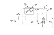
以下、本発明にかかるコンデンサーマイクロホンの実施例を、図1を参照しながら説明する。図2の従来例と同じ構成部分には同じ符号を付している。
図1において、コンデンサーマイクロホンユニット10は一方の端子がアースに接続され、他方の端子がマイクロホン回路12に接続されている。マイクロホン回路12は、マイクロホンユニット10のインピーダンスを低インピーダンスに変換するFET、増幅回路などを有してなる。マイクロホン回路12のアース側端子はアースに接続され、マイクロホン回路12の電源端子には、ファントム電源供給回路14から電源が供給されるとともに、内蔵電源電池20からも電源を供給することができるようになっている。ファントム電源供給回路14には定電流ダイオードなどからなる定電流回路16が接続され、ファントム電源使用時にマイクロホン回路12に一定の電流を供給するようにして消費電流を規定するように構成されている。
Hereinafter, an embodiment of a condenser microphone according to the present invention will be described with reference to FIG. The same components as those in the conventional example of FIG.
In FIG. 1, the
ファントム電源供給回路14にはさらにフォト−MOSリレー30の発光ダイオード32が直列に接続され、ファントム電源供給回路14からファントム電源が供給されているときは発光ダイオード32が発光するようになっている。上記内蔵電源電池20からマイクロホン回路12の電源供給回路には、上記フォト−MOSリレー30を構成する二つのMOSFET34が接続されている。この二つのMOSFET34はゲート同士が接続され、ソースとドレインが直列に接続されていて、ベースに光が照射されることにより二つのMOSFET34がオフすなわち絶縁状態となり、内蔵電源電池20からマイクロホン回路12への電源供給回路が遮断されるように接続されている。したがって、ファントム電源供給回路14からファントム電源が供給されているときは、マイクロホン回路12はファントム電源のみで動作する。これに対して、停電などによって外部からのファントム電源の供給が停止して、発光ダイオード32が消灯すると、二つのMOSFET34がオンとなり、双方向への通電が可能となる。したがって、内蔵電源電池20からマイクロホン回路12に電源が供給される。このときの二つのMOSFET34の端子間の抵抗は低く、この端子間にかかる電圧は、ショットキーダイオードなどに比べるとかなり低い。フォト−MOSリレー30として、例えば、株式会社東芝製のTLP4176Gを用いることができる。
A
フォト−MOSリレー30が上記のように接続されているため、ファントム電源供給回路14からマイクロホン回路12に電源が供給されているときは、フォト−MOSリレー30の発光ダイオード32が発光してその光束が二つのMOSFET34のゲートを照射し、二つのMOSFET34はオフとなって、内蔵電源電池20からマイクロホン回路12への電源供給回路を遮断している。これにより、ファントム電源の電流が内蔵電源電池20に流れ込むのを防止している。停電その他のトラブルなどによってファントム電源供給回路14からのファントム電源の供給が停止すると、フォト−MOSリレー30の発光ダイオード32への電源供給が停止し、発光ダイオード32が消灯する。これによりフォト−MOSリレー30の二つのMOSFET34への光束の照射が停止し、二つのMOSFET34がオンし、内蔵電源電池20からマイクロホン回路12に電源が供給されて、マイクロホン回路12は動作し続ける。このように、ファントム電源をメインとして使用し、ファントム電源にトラブルがあったとしても、自動的に内蔵電源電池20に切り替えられ、内蔵電源電池20で補助されて、動作が継続される。以上の説明から明らかなように、フォト−MOSリレー30の発光ダイオード32は、ファントム電源供給回路14に接続されてファントム電源の供給の有無を検知する検知手段を構成している。フォト−MOSリレー30の二つのMOSFET34は、内蔵電源供給回路に接続されて、上記検知手段がファントム電源の供給を検知しているとき内蔵電源供給回路を遮断するスイッチ手段を構成している。
Since the photo-
上記内蔵電源電池20のマイナス側はアースに接続されている。マイクロホン回路12の出力端子は、トランス24の一次コイル26の一方の端子に接続されている。トランス24の一次コイル26の他方の端子はアースに接続されている。マイクロホン本体には規格化された3ピンのコネクタが設けられていて、このコネクタにケーブル側コネクタが装着されることにより、外部からファントム電源が供給されるとともに、電気音響変換されてなるマイクロホン出力が外部回路に出力されるようになっている。また、上記アースがアース端子を介してケーブルのアースに接続され、外部回路のアースに接続されるようになっている。図1において符号1,2,3は上記コネクタの端子番号を示す。1番端子はアース端子、ホット側の2番端子とコールド側の3番端子は音声信号の出力端子で、上記トランス24の二次コイル28の一方の端子が2番端子に、二次コイル28の他方の端子が3番端子に接続されている。上記ケーブルと3コネクタを介して外部からファントム電源が供給され、マイクロホン内では上記二次コイル28のセンタータップがファントム電源回路14に接続され、ファントム電源がマイクロホン回路12に供給されるように構成されている。
The negative side of the built-in
内蔵電源電池20でマイクロホン回路12が動作している状態では、フォト−MOSリレー30の接点すなわち二つのMOSFET34の端子間の抵抗は、前記株式会社東芝製のTLP4176Gの場合15Ωであることから、内蔵電源電池20から供給される電流が1mAとすると、上記二つのMOSFET34の端子間での電圧降下は0.015Vである。この電圧降下の値は、前述のダイオードによる電圧降下の値と比較すればごく僅かであり、内蔵電源電池20の電圧がほぼそのままマイクロホン回路12に加えられることになり、マイクロホンの出力レベルの低下という不具合は発生しない。
In the state where the
図2に示すような従来例では、内蔵電源電池20にファントム電源から電流が流れ込むのを防止するダイオードを、内蔵電源電池20に直列に接続している。上記ダイオードには、ファントム電源からの逆流防止時に若干の逆方向電流が流れる。例えば、株式会社日立製作所製のダイオードISS198の場合、6Vの逆電圧をかけると約70μAの電流が流れ、この電流が内蔵電源電池20に流れることになり、内蔵電源電池20に不具合を生じることになる。これに対して図2に示すような本願発明の実施例によれば、フォト−MOSリレーの遮断時の抵抗は1×10の14乗Ωであることから、内蔵電源電池20に流れ込む逆電流は皆無といってよい。
In the conventional example as shown in FIG. 2, a diode that prevents current from flowing into the built-in
10 マイクロホンユニット
12 マイクロホン回路
14 ファントム電源供給回路
20 内蔵電源
30 フォト−MOSリレー
32 発光ダイオード
34 スイッチ手段としてのFET
DESCRIPTION OF
Claims (2)
ファントム電源からマイクロホン回路に至るファントム電源供給回路および内蔵電源からマイクロホン回路に至る内蔵電源供給回路と、
ファントム電源供給回路に接続されてファントム電源の供給の有無を検知する検知手段と、
上記検知手段がファントム電源の供給を検知しているとき内蔵電源供給回路を遮断するスイッチ手段と、を備え、
上記検知手段はフォト−MOSリレーが備える発光ダイオードで構成されていてファントム電源供給回路に直列に接続され、
上記スイッチ手段は上記フォト−MOSリレーが備えているMOSFETで構成され、
上記MOSFETは上記発光ダイオードの点滅によって上記内蔵電源供給回路を開閉するように接続されているコンデンサーマイクロホン。 A condenser microphone that uses a phantom power source and an internal power source that are supplied from the outside.
A built-in power supply circuit leading to the microphone circuit from phantom power supply circuit and the built-in power supply, from phantom power to the microphone circuit,
Detection means connected to the phantom power supply circuit for detecting the presence or absence of phantom power supply ;
And a switching means for cutting off the internal power supply circuit when the detecting means has detected the supply of phantom power,
The detection means is composed of a light emitting diode provided in a photo-MOS relay, and is connected in series to a phantom power supply circuit.
The switch means is composed of a MOSFET provided in the photo-MOS relay,
The MOSFET is a condenser microphone connected to open and close the built-in power supply circuit by blinking the light emitting diode .
Priority Applications (2)
| Application Number | Priority Date | Filing Date | Title |
|---|---|---|---|
| JP2005001009A JP4370522B2 (en) | 2005-01-05 | 2005-01-05 | Condenser microphone |
| US11/302,110 US20060146688A1 (en) | 2005-01-05 | 2005-12-14 | Capacitor microphone |
Applications Claiming Priority (1)
| Application Number | Priority Date | Filing Date | Title |
|---|---|---|---|
| JP2005001009A JP4370522B2 (en) | 2005-01-05 | 2005-01-05 | Condenser microphone |
Publications (3)
| Publication Number | Publication Date |
|---|---|
| JP2006191323A JP2006191323A (en) | 2006-07-20 |
| JP2006191323A5 JP2006191323A5 (en) | 2007-11-29 |
| JP4370522B2 true JP4370522B2 (en) | 2009-11-25 |
Family
ID=36640259
Family Applications (1)
| Application Number | Title | Priority Date | Filing Date |
|---|---|---|---|
| JP2005001009A Expired - Fee Related JP4370522B2 (en) | 2005-01-05 | 2005-01-05 | Condenser microphone |
Country Status (2)
| Country | Link |
|---|---|
| US (1) | US20060146688A1 (en) |
| JP (1) | JP4370522B2 (en) |
Families Citing this family (4)
| Publication number | Priority date | Publication date | Assignee | Title |
|---|---|---|---|---|
| JP4822934B2 (en) * | 2006-05-22 | 2011-11-24 | 株式会社オーディオテクニカ | Microphone circuit |
| JP5995509B2 (en) * | 2012-05-02 | 2016-09-21 | 株式会社オーディオテクニカ | Condenser microphone |
| US20160381479A1 (en) | 2015-04-10 | 2016-12-29 | Sennheiser Electronic Gmbh & Co. Kg | Method for controlling a wireless audio receiver unit and wireless audio receiver unit |
| JP6826724B2 (en) * | 2017-01-05 | 2021-02-10 | 株式会社オーディオテクニカ | Microphone |
Family Cites Families (4)
| Publication number | Priority date | Publication date | Assignee | Title |
|---|---|---|---|---|
| US4567608A (en) * | 1984-03-23 | 1986-01-28 | Electro-Voice, Incorporated | Microphone for use on location |
| JP2002077373A (en) * | 2000-08-30 | 2002-03-15 | Sony Corp | Telephone device |
| JP4528465B2 (en) * | 2001-06-08 | 2010-08-18 | 株式会社オーディオテクニカ | Microphone |
| JP4067367B2 (en) * | 2002-09-09 | 2008-03-26 | シャープ株式会社 | Load control device |
-
2005
- 2005-01-05 JP JP2005001009A patent/JP4370522B2/en not_active Expired - Fee Related
- 2005-12-14 US US11/302,110 patent/US20060146688A1/en not_active Abandoned
Also Published As
| Publication number | Publication date |
|---|---|
| US20060146688A1 (en) | 2006-07-06 |
| JP2006191323A (en) | 2006-07-20 |
Similar Documents
| Publication | Publication Date | Title |
|---|---|---|
| JP5849488B2 (en) | Switching power supply | |
| US8446185B2 (en) | Load driving device | |
| US20070230717A1 (en) | Condenser microphone circuit | |
| TWI431912B (en) | Electronic equipment having a boost dc-dc converter | |
| JP2007312260A (en) | Microphone circuit | |
| JP4473294B2 (en) | Power control device | |
| WO2013047005A1 (en) | Load driving circuit | |
| JP4370522B2 (en) | Condenser microphone | |
| US20100266140A1 (en) | Voice input/output automatic switching circuit used in hand-held microphone with speaker of communication device such as transceiver | |
| JP2008109349A (en) | Reverse current prevention circuit | |
| JPWO2007015520A1 (en) | Power supply | |
| US20090190278A1 (en) | Electronic device having reverse connection protection circuit | |
| JP2012039693A (en) | Power supply switching circuit | |
| TWI400603B (en) | Power allocating apparatus | |
| JPWO2012104980A1 (en) | Power supply device and electronic device system | |
| JP5995509B2 (en) | Condenser microphone | |
| US10151787B1 (en) | Audible ground fault buzzer circuit | |
| KR100676195B1 (en) | Apparatus for supplying power source in an organic electroluminescent device | |
| JP5561827B2 (en) | Switching power supply | |
| JP2011244659A (en) | Insulated switching dc/dc converter | |
| JP4406570B2 (en) | Power supply | |
| JP2003339117A (en) | Breakdown preventing circuit for electronic device against reverse insertion of battery | |
| JP2007097271A (en) | Switching regulator | |
| JP2008131528A (en) | Inverter amplifier | |
| JP2020155385A (en) | Lighting device of emergency illumination device, and emergency illumination device |
Legal Events
| Date | Code | Title | Description |
|---|---|---|---|
| A521 | Written amendment |
Free format text: JAPANESE INTERMEDIATE CODE: A523 Effective date: 20071016 |
|
| A621 | Written request for application examination |
Free format text: JAPANESE INTERMEDIATE CODE: A621 Effective date: 20071016 |
|
| A977 | Report on retrieval |
Free format text: JAPANESE INTERMEDIATE CODE: A971007 Effective date: 20090421 |
|
| A131 | Notification of reasons for refusal |
Free format text: JAPANESE INTERMEDIATE CODE: A131 Effective date: 20090428 |
|
| A521 | Written amendment |
Free format text: JAPANESE INTERMEDIATE CODE: A523 Effective date: 20090623 |
|
| TRDD | Decision of grant or rejection written | ||
| A01 | Written decision to grant a patent or to grant a registration (utility model) |
Free format text: JAPANESE INTERMEDIATE CODE: A01 Effective date: 20090818 |
|
| A01 | Written decision to grant a patent or to grant a registration (utility model) |
Free format text: JAPANESE INTERMEDIATE CODE: A01 |
|
| A61 | First payment of annual fees (during grant procedure) |
Free format text: JAPANESE INTERMEDIATE CODE: A61 Effective date: 20090819 |
|
| FPAY | Renewal fee payment (event date is renewal date of database) |
Free format text: PAYMENT UNTIL: 20120911 Year of fee payment: 3 |
|
| R150 | Certificate of patent or registration of utility model |
Free format text: JAPANESE INTERMEDIATE CODE: R150 |
|
| FPAY | Renewal fee payment (event date is renewal date of database) |
Free format text: PAYMENT UNTIL: 20130911 Year of fee payment: 4 |
|
| LAPS | Cancellation because of no payment of annual fees |