JP4369907B2 - Sonochemical treatment equipment - Google Patents
Sonochemical treatment equipment Download PDFInfo
- Publication number
- JP4369907B2 JP4369907B2 JP2005194238A JP2005194238A JP4369907B2 JP 4369907 B2 JP4369907 B2 JP 4369907B2 JP 2005194238 A JP2005194238 A JP 2005194238A JP 2005194238 A JP2005194238 A JP 2005194238A JP 4369907 B2 JP4369907 B2 JP 4369907B2
- Authority
- JP
- Japan
- Prior art keywords
- ultrasonic
- therapeutic
- diagnostic image
- diagnostic
- treatment
- Prior art date
- Legal status (The legal status is an assumption and is not a legal conclusion. Google has not performed a legal analysis and makes no representation as to the accuracy of the status listed.)
- Active
Links
- 230000001225 therapeutic effect Effects 0.000 claims description 114
- 230000008859 change Effects 0.000 claims description 29
- 238000002604 ultrasonography Methods 0.000 claims description 29
- 238000003745 diagnosis Methods 0.000 claims description 17
- 238000010191 image analysis Methods 0.000 claims description 14
- 230000001678 irradiating effect Effects 0.000 claims description 11
- 238000001514 detection method Methods 0.000 claims description 8
- 238000002560 therapeutic procedure Methods 0.000 claims description 6
- 238000002592 echocardiography Methods 0.000 claims description 2
- 206010028980 Neoplasm Diseases 0.000 description 42
- 238000000034 method Methods 0.000 description 37
- 230000005540 biological transmission Effects 0.000 description 27
- 239000000523 sample Substances 0.000 description 22
- 238000012545 processing Methods 0.000 description 14
- 230000008569 process Effects 0.000 description 13
- 230000003321 amplification Effects 0.000 description 10
- 238000003199 nucleic acid amplification method Methods 0.000 description 10
- 230000015271 coagulation Effects 0.000 description 9
- 238000005345 coagulation Methods 0.000 description 9
- 238000010586 diagram Methods 0.000 description 9
- 230000000875 corresponding effect Effects 0.000 description 8
- 239000003814 drug Substances 0.000 description 8
- 238000003384 imaging method Methods 0.000 description 8
- 229940079593 drug Drugs 0.000 description 7
- 239000003795 chemical substances by application Substances 0.000 description 5
- 238000012544 monitoring process Methods 0.000 description 5
- 230000001338 necrotic effect Effects 0.000 description 5
- 210000001519 tissue Anatomy 0.000 description 5
- WSFSSNUMVMOOMR-UHFFFAOYSA-N Formaldehyde Chemical compound O=C WSFSSNUMVMOOMR-UHFFFAOYSA-N 0.000 description 4
- 201000011510 cancer Diseases 0.000 description 4
- XLYOFNOQVPJJNP-UHFFFAOYSA-N water Substances O XLYOFNOQVPJJNP-UHFFFAOYSA-N 0.000 description 4
- IICCLYANAQEHCI-UHFFFAOYSA-N 4,5,6,7-tetrachloro-3',6'-dihydroxy-2',4',5',7'-tetraiodospiro[2-benzofuran-3,9'-xanthene]-1-one Chemical class O1C(=O)C(C(=C(Cl)C(Cl)=C2Cl)Cl)=C2C21C1=CC(I)=C(O)C(I)=C1OC1=C(I)C(O)=C(I)C=C21 IICCLYANAQEHCI-UHFFFAOYSA-N 0.000 description 3
- NIXOWILDQLNWCW-UHFFFAOYSA-N acrylic acid group Chemical group C(C=C)(=O)O NIXOWILDQLNWCW-UHFFFAOYSA-N 0.000 description 3
- 238000006243 chemical reaction Methods 0.000 description 3
- 230000006378 damage Effects 0.000 description 3
- 238000002474 experimental method Methods 0.000 description 3
- 230000004048 modification Effects 0.000 description 3
- 238000012986 modification Methods 0.000 description 3
- 238000001208 nuclear magnetic resonance pulse sequence Methods 0.000 description 3
- 241000196324 Embryophyta Species 0.000 description 2
- WZUVPPKBWHMQCE-UHFFFAOYSA-N Haematoxylin Chemical compound C12=CC(O)=C(O)C=C2CC2(O)C1C1=CC=C(O)C(O)=C1OC2 WZUVPPKBWHMQCE-UHFFFAOYSA-N 0.000 description 2
- 230000009471 action Effects 0.000 description 2
- 238000004458 analytical method Methods 0.000 description 2
- 230000008901 benefit Effects 0.000 description 2
- 238000002512 chemotherapy Methods 0.000 description 2
- 230000001276 controlling effect Effects 0.000 description 2
- 201000010099 disease Diseases 0.000 description 2
- 208000037265 diseases, disorders, signs and symptoms Diseases 0.000 description 2
- 238000005286 illumination Methods 0.000 description 2
- 210000000056 organ Anatomy 0.000 description 2
- 238000010186 staining Methods 0.000 description 2
- 239000000126 substance Substances 0.000 description 2
- 206010004446 Benign prostatic hyperplasia Diseases 0.000 description 1
- 206010006187 Breast cancer Diseases 0.000 description 1
- 208000026310 Breast neoplasm Diseases 0.000 description 1
- 206010060862 Prostate cancer Diseases 0.000 description 1
- 208000004403 Prostatic Hyperplasia Diseases 0.000 description 1
- 208000000236 Prostatic Neoplasms Diseases 0.000 description 1
- 230000003213 activating effect Effects 0.000 description 1
- 230000000259 anti-tumor effect Effects 0.000 description 1
- 230000004071 biological effect Effects 0.000 description 1
- 238000004364 calculation method Methods 0.000 description 1
- 210000001072 colon Anatomy 0.000 description 1
- 238000007796 conventional method Methods 0.000 description 1
- 230000002596 correlated effect Effects 0.000 description 1
- 230000007850 degeneration Effects 0.000 description 1
- 238000002059 diagnostic imaging Methods 0.000 description 1
- 230000008034 disappearance Effects 0.000 description 1
- 238000002651 drug therapy Methods 0.000 description 1
- 230000009977 dual effect Effects 0.000 description 1
- 238000004043 dyeing Methods 0.000 description 1
- 239000002961 echo contrast media Substances 0.000 description 1
- 230000000694 effects Effects 0.000 description 1
- 239000000284 extract Substances 0.000 description 1
- 210000003414 extremity Anatomy 0.000 description 1
- 230000006870 function Effects 0.000 description 1
- 230000006872 improvement Effects 0.000 description 1
- 238000004519 manufacturing process Methods 0.000 description 1
- 238000005259 measurement Methods 0.000 description 1
- 230000007246 mechanism Effects 0.000 description 1
- 239000000203 mixture Substances 0.000 description 1
- 230000017074 necrotic cell death Effects 0.000 description 1
- 229940105631 nembutal Drugs 0.000 description 1
- 208000023983 oral cavity neoplasm Diseases 0.000 description 1
- WEXRUCMBJFQVBZ-UHFFFAOYSA-N pentobarbital Chemical compound CCCC(C)C1(CC)C(=O)NC(=O)NC1=O WEXRUCMBJFQVBZ-UHFFFAOYSA-N 0.000 description 1
- 230000001737 promoting effect Effects 0.000 description 1
- 201000004240 prostatic hypertrophy Diseases 0.000 description 1
- 238000005070 sampling Methods 0.000 description 1
- 230000035945 sensitivity Effects 0.000 description 1
- 238000009214 sonodynamic therapy Methods 0.000 description 1
- 239000004575 stone Substances 0.000 description 1
- 239000000725 suspension Substances 0.000 description 1
- 230000001360 synchronised effect Effects 0.000 description 1
- 230000002194 synthesizing effect Effects 0.000 description 1
- 230000008685 targeting Effects 0.000 description 1
- 238000012360 testing method Methods 0.000 description 1
- 229940124597 therapeutic agent Drugs 0.000 description 1
- 210000000689 upper leg Anatomy 0.000 description 1
- 210000003462 vein Anatomy 0.000 description 1
- 238000012800 visualization Methods 0.000 description 1
Images


Classifications
-
- A—HUMAN NECESSITIES
- A61—MEDICAL OR VETERINARY SCIENCE; HYGIENE
- A61B—DIAGNOSIS; SURGERY; IDENTIFICATION
- A61B8/00—Diagnosis using ultrasonic, sonic or infrasonic waves
-
- A—HUMAN NECESSITIES
- A61—MEDICAL OR VETERINARY SCIENCE; HYGIENE
- A61M—DEVICES FOR INTRODUCING MEDIA INTO, OR ONTO, THE BODY; DEVICES FOR TRANSDUCING BODY MEDIA OR FOR TAKING MEDIA FROM THE BODY; DEVICES FOR PRODUCING OR ENDING SLEEP OR STUPOR
- A61M37/00—Other apparatus for introducing media into the body; Percutany, i.e. introducing medicines into the body by diffusion through the skin
- A61M37/0092—Other apparatus for introducing media into the body; Percutany, i.e. introducing medicines into the body by diffusion through the skin using ultrasonic, sonic or infrasonic vibrations, e.g. phonophoresis
-
- A—HUMAN NECESSITIES
- A61—MEDICAL OR VETERINARY SCIENCE; HYGIENE
- A61N—ELECTROTHERAPY; MAGNETOTHERAPY; RADIATION THERAPY; ULTRASOUND THERAPY
- A61N7/00—Ultrasound therapy
Description
本発明は、超音波を利用した治療装置等に関し、特に、超音波照射により生じるキャビテーションの作用で活性化される音響化学治療用の薬剤と組み合わせて治療を行う、音響化学治療装置等に関する。 The present invention relates to a therapeutic apparatus using ultrasonic waves, and more particularly to a sonochemical therapeutic apparatus that performs treatment in combination with a sonochemical therapeutic agent activated by the action of cavitation caused by ultrasonic irradiation.
超音波を医療分野に利用した装置として、超音波診断装置が広く普及している。超音波診断装置は、現在病院で使われている各種の画像診断機器の中でもリアルタイム性に優れ、安価かつ小型なために使いやすい等の長所がある。また、超音波診断装置は、元来、臓器等の形態を診断するものであったが、近年では、所定の超音波造影剤と組み合わせることによって臓器等の機能をも診断できつつある。機能診断が実現すれば、がん等の疾患をより早期に発見することができ、患者のQOL(Quality Of Life)の向上に貢献できる。 As an apparatus using ultrasonic waves in the medical field, ultrasonic diagnostic apparatuses are widely used. The ultrasonic diagnostic apparatus has advantages such as excellent real-time characteristics among various diagnostic imaging apparatuses currently used in hospitals, and is easy to use because it is inexpensive and small. In addition, the ultrasonic diagnostic apparatus originally diagnoses the form of an organ or the like, but in recent years, the function of an organ or the like can be diagnosed by combining with a predetermined ultrasonic contrast agent. If functional diagnosis is realized, diseases such as cancer can be detected at an earlier stage, which can contribute to improvement of QOL (Quality Of Life) of patients.
また、超音波は、診断だけでなく、がん等の治療にも利用されている。超音波を用いた治療方法として、生体組織に吸収されて熱に変換された超音波のエネルギにより、組織を凝固壊死させる加熱凝固治療が開示されている(例えば、非特許文献1参照)。このような加熱凝固治療は、前立腺肥大、前立腺がん、乳がん等の疾患に対して実際に行われ始めている。
このように、超音波は診断と治療とに利用できることから、患者の治療のために効率的かつ効果的な統合システムが提供されうる(例えば、特許文献1参照)。
Ultrasound is used not only for diagnosis but also for treatment of cancer and the like. As a treatment method using ultrasonic waves, a heat coagulation treatment in which the tissue is coagulated and necrosed by ultrasonic energy absorbed into a living tissue and converted into heat is disclosed (for example, see Non-Patent Document 1). Such heat coagulation treatment is actually being performed for diseases such as prostatic hypertrophy, prostate cancer, breast cancer and the like.
In this way, since ultrasound can be used for diagnosis and treatment, an efficient and effective integrated system can be provided for patient treatment (see, for example, Patent Document 1).
しかしながら、加熱凝固治療は、1kW/cm2以上の高い音響強度の収束超音波を患部に照射するために、照準がずれた際には患者への負担が増加する可能性がある。また、加熱凝固治療は、正常組織とがん化した組織とが入り組んでいるような、浸潤性や播種性のがんの治療には適さないと考えられる。 However, since the heat coagulation treatment irradiates the affected part with a focused ultrasonic wave having a high acoustic intensity of 1 kW / cm 2 or more, the burden on the patient may increase when the aim is shifted. In addition, it is considered that heat coagulation treatment is not suitable for treatment of invasive or disseminated cancer in which normal tissue and cancerous tissue are complicated.
一方、超音波と薬剤とを組み合わせることで、数W/cm2〜数10W/cm2程度の比較的低い音響強度の超音波を用いて治療を行うことができる、音響化学治療が開示されている(例えば、非特許文献2参照)。音響化学治療は、超音波照射により生じるキャビテーションと呼ばれる現象を利用して、あらかじめ患者に投与された音響化学治療用の薬剤を活性化させて、患者の治療を行う方法である。 On the other hand, by combining the ultrasonic and drug therapy can be performed using ultrasound relatively low acoustic intensity of several W / cm 2 ~ Number 10 W / cm 2, discloses an acoustic chemotherapy (For example, refer nonpatent literature 2). The sonochemical treatment is a method of treating a patient by activating a sonochemical treatment agent that has been administered to the patient in advance using a phenomenon called cavitation caused by ultrasonic irradiation.
キャビテーションは、超音波照射により気泡が発生し、発生した気泡が成長し、成長した気泡が圧縮破壊する一連の現象である。キャビテーションの最後の過程で気泡が圧縮破壊するときに、極めて高い圧力(数百気圧)と温度(数千度)が発生し、気泡近傍に特異な反応場が形成される。 Cavitation is a series of phenomena in which bubbles are generated by ultrasonic irradiation, the generated bubbles grow, and the grown bubbles compressively break. When bubbles are compressed and destroyed in the final process of cavitation, extremely high pressure (several hundred atmospheres) and temperature (several thousand degrees) are generated, and a unique reaction field is formed in the vicinity of the bubbles.
音響化学治療用の薬剤としては、例えば、ローズベンガル誘導体のように、腫瘍に集積し、キャビテーションに必要な超音波の閾値を低下させ、キャビテーションにより生じる反応場中に置かれると、例えば活性酸素を生成することによって、抗腫瘍効果を示す薬剤が開示されている(例えば、特許文献2参照)。 As a drug for sonochemical treatment, for example, a rose bengal derivative accumulates in a tumor, lowers the threshold of ultrasonic necessary for cavitation, and puts it in a reaction field generated by cavitation. A drug that exhibits an antitumor effect by being produced is disclosed (for example, see Patent Document 2).
このように、音響化学治療は、患部へのターゲッティングを薬剤と超音波とで二重に行うことができるため、非常に選択性の高い治療法となることが期待されている。 As described above, the sonochemical treatment is expected to be a highly selective treatment method because targeting to the affected area can be performed in a dual manner using the drug and the ultrasonic wave.
さらに、音響化学治療においては、従来に比べて低い音響強度の超音波でキャビテーション現象を引き起こすための超音波照射方法が開示されている。例えば、特許文献3には音場を切り替えながら超音波を照射する方法が、特許文献4には基本波にその二倍の周波数を持つ第二高調波を重畳する方法が、そして、非特許文献3には基本波と第二高調波の位相をずらして重畳する方法が開示されている。
これらの方法は、いずれも、超音波照射によって生成した気泡が照射超音波の周波数に共振する大きさになるまで成長することを促進することによって、キャビテーションを効率よく生成させる方法である。
また、一度発生した気泡を成長させるには、パルス数を3以上で超音波を継続して照射する必要があることが開示されている(例えば、非特許文献4、5参照)。
Furthermore, in sonochemical treatment, an ultrasonic irradiation method for causing a cavitation phenomenon with ultrasonic waves having a lower acoustic intensity than in the prior art is disclosed. For example, Patent Document 3 discloses a method of irradiating an ultrasonic wave while switching the sound field, Patent Document 4 discloses a method of superimposing a second harmonic having a frequency twice that of the fundamental wave, and Non-Patent Document. No. 3 discloses a method of superimposing the fundamental wave and the second harmonic with the phases shifted.
All of these methods are methods for efficiently generating cavitation by promoting the growth of bubbles generated by ultrasonic irradiation until they have a size that resonates with the frequency of the irradiated ultrasonic waves.
Further, it is disclosed that in order to grow a bubble once generated, it is necessary to continuously irradiate ultrasonic waves with a pulse number of 3 or more (see, for example, Non-Patent Documents 4 and 5).
また、超音波結石破壊や超音波加熱凝固治療中に治療部位をモニタリングする方法が複数開示されている。例えば、特許文献5には治療前に微弱な超音波で結石の位置を確認する方法が、特許文献6には複数の異なる方位からの超音波撮像で偶数倍高調波発生位置を検出し、結石の破壊やキャビテーションの圧壊している位置を確認する方法が、そして、特許文献7には偶数倍高調波を検出して気泡の生成を確認することで組織を確実に熱変性させうる温度への到達を確認する方法が開示されている。
In addition, a plurality of methods for monitoring a treatment site during ultrasonic stone destruction or ultrasonic heat coagulation treatment are disclosed. For example, Patent Document 5 discloses a method for confirming the position of a calculus with a weak ultrasonic wave before treatment, and Patent Document 6 detects an even-numbered harmonic generation position by ultrasonic imaging from a plurality of different orientations. The method of confirming the position where the destruction of the cavitation and the collapse of the cavitation are detected, and in
特に、加熱凝固治療用の超音波を照射中に診断用超音波との干渉によって超音波診断が困難になることを克服するため、超音波診断装置と加熱凝固治療装置とを同期させて、診断用の超音波が治療部位付近の可視化に用いられるときにのみ治療用超音波を停止させ治療部位の治療中の観察を可能にする手法が開示されている(例えば、非特許文献6参照)。 In particular, in order to overcome the difficulty of ultrasonic diagnosis due to interference with diagnostic ultrasound during irradiation of ultrasound for heat coagulation treatment, the diagnosis is performed by synchronizing the ultrasound diagnosis device and the heat coagulation treatment device. A technique is disclosed in which the therapeutic ultrasonic wave is stopped only when the ultrasonic wave for use is used for visualization in the vicinity of the treatment site to enable observation during treatment of the treatment site (for example, see Non-Patent Document 6).
また、加熱凝固治療において、治療用超音波の照射が停止している期間にのみ超音波診断像を得るための超音波操作を行う発明が開示されている(例えば、特許文献8、9参照)。
このように、音響化学治療は、患者への負担が少なく、効果的な腫瘍の治療方法として期待されている。また、音響化学治療では低い音響強度の超音波でも、治療の源となるキャビテーション現象を効率的に引き起こす超音波の照射方法が開示されている。
しかしながら、このような照射方法を用いた場合でも、従来の技術を用いてはキャビテーション現象を再現性良く引き起こすことは難しいという課題があった。
さらに、治療用の超音波を照射している間は適切な診断画像を生成することができないために、超音波の照射から数日経過して、実際に腫瘍の変性を確認するまでは治療効果を判定できないという問題があった。
Thus, sonochemical treatment is expected to be an effective tumor treatment method with less burden on patients. In the sonochemical treatment, there is disclosed a method of irradiating an ultrasonic wave that efficiently causes a cavitation phenomenon that is a source of treatment even with an ultrasonic wave having a low acoustic intensity.
However, even when such an irradiation method is used, there is a problem that it is difficult to cause the cavitation phenomenon with high reproducibility using the conventional technique.
Furthermore, since it is not possible to generate an appropriate diagnostic image while irradiating therapeutic ultrasound, a therapeutic effect is observed until several days after the ultrasound irradiation and actually confirming tumor degeneration. There was a problem that could not be determined.
そこで、本発明は、音響化学治療を行うのに有効なキャビテーションによる気泡生成を確認しつつ腫瘍等の治療を行うことができる装置等を提供することを目的とする。 Accordingly, an object of the present invention is to provide a device that can treat a tumor or the like while confirming bubble generation by cavitation effective for performing sonochemical treatment.
前記課題を解決するために、本発明の音響化学治療装置は、診断用の超音波を照射する第1の超音波照射手段と、治療用の超音波を照射する第2の超音波照射手段と、超音波エコーを検出するエコー検出手段と、前記第1の超音波照射手段を介して前記診断用の超音波を照射し、前記エコー検出手段を介して前記診断用の超音波に対応する前記超音波エコーを検出する診断用制御手段と、検出された前記超音波エコーに基づいて診断画像を生成する診断画像生成手段と、生成された前記診断画像に基づいてキャビテーションに関連する気泡を検出する診断画像分析手段と、前記第2の超音波照射手段を介して前記治療用の超音波を照射する治療用制御手段と、を備えた音響化学治療装置であって、前記治療用制御手段は、前記第2の超音波照射手段を介した前記治療用の超音波を、所定のパルス数および休止期間で照射する制御を行うパルス制御手段と、前記気泡が検出された場合には前記治療用の超音波の音響強度を低下させ、前記気泡が検出されない場合には前記治療用の超音波の音響強度を増加させる増幅手段と、を含み、前記診断画像生成手段は、前記治療用の超音波の前記休止期間における前記超音波エコーに基づいて前記診断画像を生成することを特徴とする音響化学治療装置である。
なお、他の発明に関しては、本明細書中で明らかにする。
In order to solve the above-described problems, a sonochemical treatment apparatus according to the present invention includes a first ultrasonic irradiation unit that irradiates diagnostic ultrasonic waves, and a second ultrasonic irradiation unit that irradiates therapeutic ultrasonic waves. , an echo detecting means for detecting the ultrasonic echo, the said first through ultrasonic irradiation means irradiates the ultrasonic waves for the diagnosis, corresponding to the ultrasound for the diagnosis through the echo detection unit Diagnostic control means for detecting an ultrasonic echo, diagnostic image generating means for generating a diagnostic image based on the detected ultrasonic echo, and bubbles related to cavitation are detected based on the generated diagnostic image A sonochemical treatment apparatus comprising: a diagnostic image analyzing unit; and a therapeutic control unit that irradiates the therapeutic ultrasonic wave via the second ultrasonic irradiation unit, wherein the therapeutic control unit includes: The second ultrasonic illumination Ultrasound for the treatment via means, reducing the acoustic intensity of the ultrasound for the therapy and pulse control means for controlling illumination with a predetermined number of pulses and rest periods, when the bubble is detected is, when the bubble is not detected includes an amplification means for increasing the acoustic intensity of the ultrasound for the therapy, the diagnosis image generation means, said in the idle period of the ultrasound for the therapy ultrasound a sonodynamic therapy system and generates the diagnosis image based on echo.
Other inventions will be clarified in this specification.
本発明によれば、音響化学治療を行うのに有効なキャビテーションによる気泡生成を確認しつつ腫瘍等の治療を行うことができる。 ADVANTAGE OF THE INVENTION According to this invention, a tumor etc. can be treated, confirming the bubble production | generation by the cavitation effective in performing sonochemical treatment.
以下、本発明を実施するための最良の形態(以下「実施形態」という)について、適宜図面を参照しながら詳細に説明する。 Hereinafter, the best mode for carrying out the present invention (hereinafter referred to as “embodiment”) will be described in detail with reference to the drawings as appropriate.
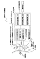
図1は、本実施形態の音響化学治療装置の構成を示すブロック図である。図1に示すように、音響化学治療装置1は、診断用プローブ2と、治療用トランスデューサ3と、装置本体4と、表示手段5とを含んで構成される。
FIG. 1 is a block diagram showing the configuration of the sonochemical treatment apparatus of this embodiment. As shown in FIG. 1, the sonochemical treatment device 1 includes a
そして、対象部位7を含む被検体6には、所定の音響化学治療用の薬剤(以下「音響化学薬剤」という)が投与されている。この音響化学薬剤は、対象部位7への治療用の超音波の照射により生じるキャビテーションの作用で活性化されるものであれば、その組成を特に限定しないが、さらに、治療を所望する対象部位7に局在しやすい性質や、キャビテーションに必要な超音波の閾値を低下させる性質を有していることが好ましい。
なお、「被検体」とは、本実施形態の音響化学治療装置1による治療対象を意味するが、その内部でキャビテーションが起こりうる構成を有していれば、どのようなものであっても構わない。例えば、被検体6は、動植物(ヒトを含む)、動植物の生体組織や、容器内に保持された懸濁液等である。
Then, a predetermined sonochemical treatment drug (hereinafter referred to as “acoustic chemical drug”) is administered to the subject 6 including the
The “subject” means a subject to be treated by the sonochemical treatment apparatus 1 of the present embodiment, but may be anything as long as it has a configuration in which cavitation can occur. Absent. For example, the subject 6 is an animal or plant (including a human), a living tissue of an animal or plant, a suspension held in a container, or the like.
<診断用プローブ>
診断用プローブ2(第1の超音波照射手段、エコー検出手段)は、被検体6を診断するために、被検体6の対象部位7に対して診断用の超音波パルスを照射し、この診断用の超音波パルスに対応する超音波エコーを受信するものである。
診断用プローブ2は、電気信号を振動に変換し、また、振動を電気信号に変換する振動子2aを含んで構成される。この振動子2aには、例えば、磁気ひずみ共振子や圧電共振子等を利用することができる。また、被検体6における所定の範囲を診断するためには、振動子2aを複数配列させることによって、それぞれの振動子2aに対応する複数の走査線を表示手段5に表示できることが好ましい。なお、振動子2aは、広範な範囲を診断するために、平面や凸面に配列していることが好ましい。
そして、診断用プローブ2は、装置本体4に接続している。
<Diagnostic probe>
The diagnostic probe 2 (first ultrasonic irradiation means, echo detection means) irradiates the
The
The
<治療用トランスデューサ>
治療用トランスデューサ3(第2の超音波照射手段)は、被検体6を治療するために、被検体6の対象部位7に対して治療用の超音波パルスを照射するものであって、基本波を照射する治療用基本波送信トランスデューサ31と、基本波の2倍の周波数の第二高調波を照射する治療用第二高調波送信トランスデューサ32を含んで構成される。
治療用基本波送信トランスデューサ31および治療用第二高調波送信トランスデューサ32の構成は、前記した診断用プローブ2と同様の構成とすることができる。なお、振動子31aおよび32aは、超音波を収束させるために、平面や凹面に配列(振動子が1つの場合には平面や凹面に形成)していることが好ましい。例えば、振動子31aおよび32aは、直径6cmF数1の球面上に配置され、幾何学焦点が同一になるように設計することができる。
このように、治療用トランスデューサ3を構成したことにより、対象部位7において基本波と第二高調波が容易に重畳し、より効率的に気泡を生成させることができる
そして、治療用基本波送信トランスデューサ31および治療用第二高調波送信トランスデューサ32は、それぞれ、装置本体4に接続している。
<Treatment transducer>
The therapeutic transducer 3 (second ultrasonic irradiation means) irradiates the
The configurations of the therapeutic fundamental
By configuring the therapeutic transducer 3 in this manner, the fundamental wave and the second harmonic can be easily superimposed on the
また、前記した診断用プローブ2、治療用基本波送信トランスデューサ31および治療用第二高調波送信トランスデューサ32は、感度よく超音波パルスの送受信を行うために、例えば、脱気水のように、超音波減衰率の少ない物質を含むマッチング層8を介して被検体6に設置される。
また、診断用プローブ2、治療用基本波送信トランスデューサ31および治療用第二高調波送信トランスデューサ32は、図示されない、超音波照射面の方向を測定できる位置検出装置と回転機構を含む固定具により互いに連結する構成としてもよい。このような構成とすることによって、治療用トランスデューサ3の位置決めを容易に行うことができる。
In addition, the above-described
Further, the
<装置本体>
装置本体4は、被検体6から収集した超音波エコーに対応する電気信号(以下「エコー信号」という)に対する処理や、超音波送受信に関する制御、診断画像の生成・表示・分析等に関する制御を行う。
ここで、装置本体4は、診断用制御部42と、治療用制御部43と、診断画像処理部44と、を含んで構成される。
<Main unit>
The apparatus main body 4 performs processing on electrical signals (hereinafter referred to as “echo signals”) corresponding to ultrasonic echoes collected from the subject 6, control on ultrasonic transmission / reception, control on generation / display / analysis of diagnostic images, and the like. .
Here, the apparatus main body 4 includes a diagnostic control unit 42, a treatment control unit 43, and a diagnostic image processing unit 44.
なお、装置本体4の各部42〜44は、CPU(Central Processing Unit)と、ROM(Read Only Memory)やRAM(Random Access Memory)等からなるメモリと、ハードディスク装置等を含んで構成される。装置本体4の各部42〜44は、メモリまたはハードディスク装置に格納されたプログラムまたはデータに相当する。そして、CPUがメモリにプログラムを読み出して演算処理を実行することにより、各処理が実現されるものとする。
また、各部42、43は、さらに、送受信される超音波を制御するための回路を適宜備えて構成される。
Each unit 42 to 44 of the apparatus main body 4 includes a CPU (Central Processing Unit), a memory including a ROM (Read Only Memory) and a RAM (Random Access Memory), a hard disk device, and the like. Each unit 42 to 44 of the apparatus main body 4 corresponds to a program or data stored in a memory or a hard disk device. And each process shall be implement | achieved when CPU reads a program to memory and performs a calculation process.
Moreover, each part 42 and 43 is further provided with the circuit for controlling the ultrasonic wave transmitted / received suitably, and is comprised.
<診断用制御部>
診断用制御部42は、診断用プローブ2と電気的に接続しており、診断用の超音波の送受信に関する制御を行うものである。
そして、診断用制御部42は、通常の超音波診断装置で使用される概ね3〜10MHz程度の周波数および概ね1W/cm2以下の音響強度の超音波を、診断用プローブ2を介して送受信できるように構成されている。
特に、診断用制御部42は、キャビテーションに関連する気泡の生成を選択的に検出するために、複数の異なる超音波の照射方法によって得られる信号を比較して非線形成分を抽出し、非線形成分を強調できる撮像方法に基づいて構成されることが好適である。
<Diagnostic control unit>
The diagnostic control unit 42 is electrically connected to the
The diagnostic control unit 42 can transmit and receive an ultrasonic wave having a frequency of about 3 to 10 MHz and an acoustic intensity of about 1 W / cm 2 or less used in a normal ultrasonic diagnostic apparatus via the
In particular, the diagnostic control unit 42 extracts a nonlinear component by comparing signals obtained by a plurality of different ultrasonic irradiation methods in order to selectively detect generation of bubbles related to cavitation. It is preferable to be configured based on an imaging method that can be emphasized.
診断用制御部42が、前記撮像方法に基づいて構成される場合に、診断用の超音波の送受信に関する制御を行う手順について説明する。 A procedure for performing control related to transmission / reception of diagnostic ultrasonic waves when the diagnostic control unit 42 is configured based on the imaging method will be described.
診断用制御部42は、診断用の超音波パルスに対応する所定の基本波からなる電気信号(適宜「基本波信号」という)を生成して診断用プローブ2に送信するとともに、診断用プローブ2からのエコー信号を図示しない増幅回路により増幅し、診断画像生成部441へ出力する。
あわせて、診断用制御部42は、それぞれの走査線に対して基本波信号と逆位相のパルス信号(適宜「逆位相信号」という)を生成し、診断画像生成部441へ出力する。
The diagnostic control unit 42 generates an electrical signal composed of a predetermined fundamental wave corresponding to the diagnostic ultrasonic pulse (referred to as “fundamental wave signal” as appropriate) and transmits it to the
In addition, the diagnostic control unit 42 generates a pulse signal having an opposite phase to the fundamental wave signal (referred to as an “inverse phase signal” as appropriate) for each scanning line, and outputs the pulse signal to the diagnostic image generation unit 441.
<診断画像処理部>
診断画像処理部44は、診断用制御部42から入力されたエコー信号と逆位相信号から、非線形成分を強調するような診断画像を生成し、分析する処理を行うものである。
診断画像処理部44は、診断画像を生成する診断画像生成部441と、生成した診断画像を分析する診断画像分析部442と、診断画像を表示手段5に表示させる診断画像表示部443とを含んで構成される。
<Diagnostic image processing unit>
The diagnostic image processing unit 44 performs a process of generating and analyzing a diagnostic image that emphasizes the nonlinear component from the echo signal and the antiphase signal input from the diagnostic control unit 42.
The diagnostic image processing unit 44 includes a diagnostic image generation unit 441 that generates a diagnostic image, a diagnostic image analysis unit 442 that analyzes the generated diagnostic image, and a diagnostic image display unit 443 that causes the display unit 5 to display the diagnostic image. Consists of.
ここで、診断画像生成部441が、受信したエコー信号と逆位相信号に基づいて、診断画像を生成する手順の一例を説明する。
まず、診断画像生成部441は、受信したエコー信号と逆位相信号とを図示しないA/D変換回路により信号処理に適したサンプリング周波数でサンプリングして、デジタル信号に変換する。
Here, an example of a procedure in which the diagnostic image generation unit 441 generates a diagnostic image based on the received echo signal and antiphase signal will be described.
First, the diagnostic image generation unit 441 samples the received echo signal and antiphase signal at a sampling frequency suitable for signal processing by an A / D conversion circuit (not shown), and converts the sampled signal into a digital signal.
そして、診断画像生成部441は、エコー信号と逆位相信号にそれぞれ対応するデジタル信号の重畳処理を行う。エコー信号に含まれる基本波と非線形成分のうち、基本波が逆位相信号によって打ち消されることによって、差分として非線形成分を抽出することができる。この非線形成分は、被検体6に体積変化の大きい成分が含まれていると発生しやすい。従って、非線形成分を強調するような撮像方法は、一般に超音波診断に使用されるBモードに比べ、被検体6内部の気泡を検出するのに好適である。 Then, the diagnostic image generation unit 441 performs superimposing processing of digital signals corresponding to the echo signal and the antiphase signal, respectively. Of the fundamental wave and the non-linear component included in the echo signal, the non-linear component can be extracted as a difference by canceling the fundamental wave by the antiphase signal. This nonlinear component is likely to occur when the subject 6 includes a component having a large volume change. Therefore, an imaging method that emphasizes the non-linear component is suitable for detecting bubbles inside the subject 6 as compared with the B mode generally used for ultrasonic diagnosis.
なお、通常、非線形成分は、基本波の周波数のn倍の周波数からなる高調波と、基本波のn/m倍の周波数からなる分調波が含まれる(ただし、nおよびmは任意の自然数)。本実施形態においては、非線形成分を用いてキャビテーションに関する気泡を検出することができれば特に周波数を限定しないが、基本波の1/3、1/2、1のn倍(1≦n≦3)の周波数に基づいて診断画像を生成した場合には、より鮮明な気泡を検出することができる。 In general, the nonlinear component includes a harmonic wave having a frequency n times the fundamental wave frequency and a subharmonic wave having a frequency n / m times the fundamental wave (where n and m are arbitrary natural numbers). ). In the present embodiment, the frequency is not particularly limited as long as a bubble related to cavitation can be detected using a non-linear component, but the frequency is 1/3, 1/2, or 1 times the fundamental wave (1 ≦ n ≦ 3). When a diagnostic image is generated based on the frequency, clearer bubbles can be detected.
そして、診断画像生成部441は、この非線形成分から診断画像を生成する処理を行う。この診断画像生成処理は、超音波画像診断の分野において従来公知の装置構成によって実現できる。
なお、診断画像生成部441は、重畳前のエコー信号や、重畳後に抽出された非線形成分に対して、例えば、高速フーリエ変換等の周波数解析や、複数の信号の大きさ・符号等を任意に変更して合成することにより、非線形成分をさらに強調させる処理を行ってもよい。
そして、診断画像生成部441は、生成した診断画像を、診断画像表示部443へ出力して表示手段5に表示させるとともに、診断画像分析部442へ出力する。
Then, the diagnostic image generation unit 441 performs a process of generating a diagnostic image from this nonlinear component. This diagnostic image generation processing can be realized by a conventionally known apparatus configuration in the field of ultrasonic image diagnosis.
Note that the diagnostic image generation unit 441 arbitrarily performs frequency analysis such as fast Fourier transform, multiple signal sizes and codes, etc., on the echo signal before superimposition and the nonlinear component extracted after superimposition. A process of further emphasizing the nonlinear component may be performed by changing and synthesizing.
Then, the diagnostic image generation unit 441 outputs the generated diagnostic image to the diagnostic image display unit 443 to be displayed on the display unit 5 and to the diagnostic image analysis unit 442.
診断画像分析部442は、診断画像生成部441によって生成された診断画像からキャビテーションに関連する気泡を検出するものである。
例えば、診断画像分析部442は、治療用トランスデューサ3を介した治療用の超音波の照射前と照射後との診断画像を比較して、診断画像上の輝度があらかじめ設定した比率を超えた場合には、その領域を気泡が発生した領域と判定する処理を行う。
そして、診断画像分析部442により検出された気泡の情報は、治療用制御部43に出力される。
The diagnostic image analysis unit 442 detects bubbles related to cavitation from the diagnostic image generated by the diagnostic image generation unit 441.
For example, when the diagnostic image analysis unit 442 compares the diagnostic images before and after the irradiation of the therapeutic ultrasonic waves via the therapeutic transducer 3 and the luminance on the diagnostic image exceeds a preset ratio, First, a process of determining the area as an area where bubbles are generated is performed.
The information on the bubbles detected by the diagnostic image analysis unit 442 is output to the treatment control unit 43.
なお、診断画像分析部442は、気泡が発生・消失したときの超音波の情報を、音響化学薬剤の種類や被検体のデータと関連づけて、図示しないデータベースに記憶させる作業を行う構成とすることもできる。 The diagnostic image analysis unit 442 is configured to perform an operation of storing ultrasonic information when bubbles are generated / disappeared in a database (not shown) in association with the type of the sonochemical agent and the data of the subject. You can also.
<治療用制御部>
治療用制御部43は、治療用基本波送信トランスデューサ31および治療用第二高調波送信トランスデューサ32と電気的に接続しており、治療用の超音波の送信に関する制御を行うものである。
<Treatment control unit>
The therapeutic control unit 43 is electrically connected to the therapeutic fundamental
治療用制御部43は、通常の超音波治療装置で使用される概ね0.5〜4.5MHz程度の周波数および300W/cm2以下の音響強度の超音波を、治療用基本波送信トランスデューサ31および治療用第二高調波送信トランスデューサ32を介して送信できるように構成されている。このような構成とすることによって、被検体6内でのキャビテーション生成に必要な周波数と音響強度の超音波を照射することができる。
ここで、治療用制御部43は、パルス生成手段431と、増幅手段432と、位相変調手段433とを含んで構成される。
The therapeutic control unit 43 generates ultrasonic waves having a frequency of approximately 0.5 to 4.5 MHz and an acoustic intensity of 300 W / cm 2 or less, which are used in a normal ultrasonic therapy apparatus, and the fundamental
Here, the therapeutic control unit 43 includes a pulse generation unit 431, an amplification unit 432, and a phase modulation unit 433.
パルス生成手段(パルス制御手段)431は、治療用の超音波の照射時間と、休止期間と、超音波照射の終了タイミングとを規定する、パルス信号を生成するものである。ここで、超音波の照射時間とは、1パルス時間とパルス数とを乗じたものである。例えば、パルス生成手段431は、任意波形生成装置により実現できる。 The pulse generation means (pulse control means) 431 generates a pulse signal that defines the irradiation time of treatment ultrasonic waves, the rest period, and the end timing of ultrasonic irradiation. Here, the ultrasonic irradiation time is obtained by multiplying one pulse time by the number of pulses. For example, the pulse generation unit 431 can be realized by an arbitrary waveform generation device.
パルス生成手段431は、パルス信号を、新たな気泡の発生および一旦発生した気泡の成長に必要なパルス数と、一旦生成した気泡が消滅しない時間以内の休止期間との範囲で生成するものである。
この気泡の生成に必要なパルス数は、通常の超音波診断装置で使用される診断用の超音波のパルス数よりも大であることが好ましい。
さらに、非特許文献4、5には、一度発生した気泡を成長させるには、パルス数3以上超音波を継続して照射する必要があることが開示されていることから、パルス数は3以上であることがより好ましい。
また、休止期間を500msまで長くしても、気泡の成長が継続可能なことが、本発明者らの実験により明らかとなっている。なお、休止期間の下限値に関しては、適切な診断画像を生成できる時間が確保されれば特に限定しない。
The pulse generation means 431 generates a pulse signal in the range of the number of pulses necessary for the generation of new bubbles and the growth of bubbles once generated, and the pause period within which the generated bubbles do not disappear. .
It is preferable that the number of pulses necessary for the generation of the bubbles is larger than the number of diagnostic ultrasonic pulses used in a normal ultrasonic diagnostic apparatus.
Furthermore, Non-Patent Documents 4 and 5 disclose that in order to grow a bubble once generated, it is necessary to continuously irradiate ultrasonic waves with a pulse number of 3 or more. It is more preferable that
Further, it has been clarified by experiments by the present inventors that the bubble growth can be continued even if the pause period is increased to 500 ms. Note that the lower limit value of the pause period is not particularly limited as long as a time during which an appropriate diagnostic image can be generated is secured.
また、パルス生成手段431は、診断画像分析部442から入力された気泡の情報に基づいて、超音波照射の終了タイミングを決定するものである。具体的には、パルス生成手段431は、診断画像分析部442から気泡が検出された旨の情報が入力されると、図示しない計時手段により計時を開始し、気泡検出が入力された時点から所定の時間経過後に、パルス信号の生成を停止する処理を行うものである。例えば、気泡が検出されてから、1分後に停止する処理を行うことによって、過剰な治療用の超音波を被検体に照射することなく充分な治療効果を得ることができる。
ここで、パルス生成手段431により生成されたパルス信号は、増幅手段432に出力される。
Further, the pulse generation means 431 determines the end timing of the ultrasonic irradiation based on the bubble information input from the diagnostic image analysis unit 442. Specifically, when information indicating that a bubble has been detected is input from the diagnostic image analysis unit 442, the pulse generation unit 431 starts timing by a timing unit (not shown), and the predetermined time from when the bubble detection is input. After the elapse of time, processing for stopping the generation of the pulse signal is performed. For example, a sufficient treatment effect can be obtained without irradiating the subject with excessive therapeutic ultrasonic waves by performing a process of stopping one minute after the bubble is detected.
Here, the pulse signal generated by the pulse generation unit 431 is output to the amplification unit 432.
増幅手段432は、パルス信号の電圧を任意の増幅比で増幅するものである。例えば、増幅手段432は、アンプにより実現できる。
増幅手段432は、パルス信号を一律の増幅比で増幅するだけでなく、経時的に変化する増幅比で増幅することができる。すなわち、治療用トランスデューサ3から照射される超音波の音響強度は、増幅手段432によって自在に制御することができる。
The amplifying unit 432 amplifies the voltage of the pulse signal with an arbitrary amplification ratio. For example, the amplification unit 432 can be realized by an amplifier.
The amplifying unit 432 can amplify the pulse signal not only at a uniform amplification ratio but also at an amplification ratio that changes over time. That is, the acoustic intensity of the ultrasonic wave irradiated from the therapeutic transducer 3 can be freely controlled by the amplifying means 432.
なお、本発明者らによって、一旦生成された気泡を成長させるには、新たに気泡を発生させるときのようなエネルギを必要としないことが明らかとなった。また、先に生成した気泡が圧縮破壊した際の微小な気泡残渣を新たな気泡の核とすることで、キャビテーションのステップを1段階減らし、継続した気泡の発生〜成長に必要な超音波の音響強度の閾値を下げることができることが明らかになった。
このように、キャビテーションに関連する気泡の生成に必要なエネルギを小さくすることができるので、被検体6に対して超音波の照射量を減少させることができ、被検体6の負担を軽減させることができる。
It has been clarified by the present inventors that, in order to grow a bubble once generated, it does not require energy as in the case of newly generating a bubble. In addition, by using the minute bubble residue when the previously generated bubble is compressed and destroyed as the core of the new bubble, the cavitation step is reduced by one step, and the ultrasonic sound necessary for continuous generation and growth of the bubble is reduced. It became clear that the intensity threshold could be lowered.
In this way, since the energy required for generating bubbles related to cavitation can be reduced, the amount of ultrasonic irradiation to the subject 6 can be reduced, and the burden on the subject 6 can be reduced. Can do.
そこで、本実施形態においては、増幅手段432は、診断画像分析部442から気泡が検出された旨の情報が入力されると、治療用の超音波の音響強度を所定の値に下げる制御を行う構成としている。
気泡生成後の所定の音響強度は、気泡生成確認前に照射されていた治療用の超音波の音響強度よりも低い音響強度で照射することによって、一旦生成された気泡の成長と、新たな気泡の発生とを維持しつつ、被検体への負担を軽減させることができる。より被検体への負担を軽減させるためには、1/20以上1/10以下に音響強度を低下させることが好適である。なお、それ以下に低下させた場合には、気泡の成長が維持されない場合があるので、適宜診断画像による輝度の変化を確認しながら適切な音響強度を決定することが好ましい。
ここで、増幅手段432により増幅されたパルス信号は、前記した治療用トランスデューサ3に出力される。
Therefore, in the present embodiment, when the information indicating that bubbles are detected is input from the diagnostic image analysis unit 442, the amplification unit 432 performs control to reduce the acoustic intensity of the therapeutic ultrasound to a predetermined value. It is configured.
The predetermined acoustic intensity after the generation of the bubbles is such that the bubbles generated once and new bubbles are generated by irradiating with an acoustic intensity lower than the acoustic intensity of the therapeutic ultrasonic wave irradiated before the bubble generation is confirmed. It is possible to reduce the burden on the subject while maintaining the occurrence of this. In order to further reduce the burden on the subject, it is preferable to reduce the acoustic intensity to 1/20 or more and 1/10 or less. In addition, since it may not maintain a bubble growth when it reduces below it, it is preferable to determine suitable acoustic intensity, confirming the change of the brightness | luminance by a diagnostic image suitably.
Here, the pulse signal amplified by the amplification means 432 is output to the therapeutic transducer 3 described above.
位相変調手段433は、治療用基本波送信トランスデューサ31と、治療用第二高調波送信トランスデューサ32とを介して送信する基本波と第二高調波との位相差を任意に設定できる。また、経時的に位相差を変更させることも可能である。このような構成とすることによって、治療用トランスデューサ3から照射される超音波を、被検体6の対象部位7において適切に重畳させることができる。例えば、基本波と第二高調波との位相をずらし、周期の間隔を10ms以上とすることで、キャビテーションをより効率よく引き起こせることが、本発明者らの実験により明らかになっている。
The phase modulation means 433 can arbitrarily set the phase difference between the fundamental wave and the second harmonic wave transmitted via the therapeutic fundamental
<<音響化学治療装置の制御方法>>
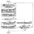
以下、図2に示すフローチャートを参照して、被検体の治療を行う場合の音響化学治療装置の制御方法を説明する。
<< Sonic Chemotherapy Control Method >>
Hereinafter, with reference to the flowchart shown in FIG. 2, the control method of the sonochemical treatment apparatus when treating a subject will be described.
あらかじめ、操作者は、診断用プローブ2により対象部位7の診断画像を取得し、診断画像を参照しながら、治療用基本波送信トランスデューサ31および治療用第二高調波送信トランスデューサ32から照射される治療用の超音波の焦点位置を、対象部位7の治療部位に合わせているものとする。
まず、音響化学治療装置1の治療用制御部43は、治療用トランスデューサ3を介して、治療用の超音波を所定のパルス数と休止期間で照射させる(ステップS01)。
なお、前記したように、このパルス数と休止期間は、気泡の成長が継続する範囲である。
また、治療用基本波送信トランスデューサ31および治療用第二高調波送信トランスデューサ32を介して、所定の周波数の基本波と前記基本波の2倍の周波数の第二高調波からなる治療用の超音波を照射し、対象部位7上で重畳させることが好ましい。
The operator acquires a diagnostic image of the
First, the therapeutic control unit 43 of the sonochemical treatment device 1 irradiates therapeutic ultrasonic waves with a predetermined number of pulses and a rest period via the therapeutic transducer 3 (step S01).
As described above, the number of pulses and the pause period are ranges in which bubble growth continues.
Also, therapeutic ultrasonic waves comprising a fundamental wave having a predetermined frequency and a second harmonic having a frequency twice as high as the fundamental wave via the treatment fundamental
次に、音響化学治療装置1の診断用制御部42は、診断用プローブ2を介して被検体6の対象部位7に診断用の超音波を照射し、診断用プローブ2を介して受信したエコー信号を診断画像処理部44に送信する(ステップS02)。
Next, the diagnostic control unit 42 of the sonochemical treatment device 1 irradiates the
そして、音響化学治療装置1の診断画像処理部44は、診断画像生成部441によって、治療用の超音波の休止期間におけるエコー信号に基づいて診断画像を生成する(ステップS03)。 Then, the diagnostic image processing unit 44 of the sonochemical treatment device 1 uses the diagnostic image generation unit 441 to generate a diagnostic image based on the echo signal in the rest period of the therapeutic ultrasound (step S03).
そして、音響化学治療装置1の診断画像分析部442は、気泡が検出されたかどうかを判定する(ステップS04)。そして、音響化学治療装置1の診断画像分析部442が、気泡を検出した場合には(ステップS04でYes)、気泡を検出した旨を治療用制御部43に送信する。 And the diagnostic image analysis part 442 of the sonochemical treatment apparatus 1 determines whether the bubble was detected (step S04). Then, when the diagnostic image analysis unit 442 of the sonochemical treatment device 1 detects a bubble (Yes in step S04), the fact that the bubble has been detected is transmitted to the treatment control unit 43.
そして、音響化学治療装置1の治療用制御部43は、気泡の検出を受信すると、計時を開始しつつ、治療用の超音波を所定の音響強度に低下させる制御を行う(ステップS05)。 And the therapeutic control part 43 of the sonochemical treatment apparatus 1 will perform control which reduces the ultrasonic wave for treatment to predetermined | prescribed acoustic intensity, starting time measurement, if the detection of a bubble is received (step S05).
そして、音響化学治療装置1の治療用制御部43は、気泡の検出を受信してから所定時間経過後に、治療用の超音波の照射を停止する制御を行う(ステップS06)。 Then, the therapeutic control unit 43 of the sonochemical treatment device 1 performs control to stop the irradiation of therapeutic ultrasonic waves after a predetermined time has elapsed after receiving the detection of the bubbles (step S06).
ステップS04において、音響化学治療装置1の診断画像分析部442が、気泡を検出しなかった場合には(ステップS04でNo)、気泡を検出しなかった旨を治療用制御部43に送信する。 In step S04, when the diagnostic image analysis unit 442 of the sonochemical treatment device 1 does not detect the bubble (No in step S04), it transmits to the treatment control unit 43 that the bubble has not been detected.
そして、音響化学治療装置1の治療用制御部43は、治療用の超音波の音響強度を増加させる制御を行う(ステップS07)。
そして、音響化学治療装置1の治療用制御部43は、増加させた音響強度が所定の上限値を超えていないかどうかを判定し(ステップS08)、所定の上限値を超えない場合には(ステップS08でYes)、ステップS01の処理に戻る。
Then, the therapeutic control unit 43 of the sonochemical treatment device 1 performs control to increase the acoustic intensity of the therapeutic ultrasonic wave (step S07).
Then, the treatment control unit 43 of the sonochemical treatment device 1 determines whether or not the increased acoustic intensity exceeds the predetermined upper limit value (step S08). Yes in step S08), the process returns to step S01.
一方、ステップS08において、増加させた音響強度が所定の上限値を超えた場合には(ステップS08でNo)、気泡を生成できなかったものとして処理を終了する。 On the other hand, if the increased sound intensity exceeds the predetermined upper limit value in step S08 (No in step S08), the process is terminated assuming that bubbles could not be generated.
以上示したように、本実施形態の音響化学治療装置1によれば、音響化学治療において照射する治療用の超音波の音響強度を必要最低限に抑え、被検体6への負担を低減した超音波照射を行うことが可能である。 As described above, according to the sonochemical treatment apparatus 1 of the present embodiment, the supersonic wave intensity of the therapeutic ultrasound to be irradiated in sonochemical treatment is suppressed to the necessary minimum, and the burden on the subject 6 is reduced. It is possible to perform acoustic wave irradiation.
なお、本発明は、前記した実施形態に限定されない。
本実施形態の診断用制御部42は、気泡を検出できるものであれば、前記した撮像方法に限定されない。例えば、診断用制御部42を、公知のパルスインバージョンモードやセカンドハーモニック法に基づいて構成してもよい。
The present invention is not limited to the above-described embodiment.
The diagnostic control unit 42 of the present embodiment is not limited to the imaging method described above as long as it can detect bubbles. For example, the diagnostic control unit 42 may be configured based on a known pulse inversion mode or a second harmonic method.
また、治療用トランスデューサ3からの超音波照射は、診断用プローブ2による超音波送受信と同期して行わせることができるように構成してもよい。この場合には、例えば、診断用プローブ2と、治療用トランスデューサ3から、交互に超音波を照射するようなパルスシーケンスとすることができる。そして、診断画像生成部441は、診断用プローブ2から照射される診断用の超音波に対応する超音波エコーに基づいて、診断画像を生成する。
Moreover, you may comprise so that ultrasonic irradiation from the therapeutic transducer 3 can be performed synchronizing with the ultrasonic transmission / reception by the
また、本実施形態においては、非線形成分を抽出するためのエコー信号と逆位相信号とを重畳する処理は、それぞれをデジタル信号に変換した後に重畳したが、超音波の段階や、電気信号の段階で、重畳処理を行う構成としてもよい。 Further, in the present embodiment, the process of superimposing the echo signal and the antiphase signal for extracting the non-linear component is superposed after converting each signal into a digital signal. Thus, a configuration in which superimposition processing is performed may be employed.
また、本実施形態においては、診断画像上の輝度の変化をモニタするために、治療用の超音波の音響強度を増加させ、所定の上限値まで音響強度を増加させても輝度の変化が検出されなかった場合には、気泡が生成されなかったものとして処理を終了したが、さらに治療用の超音波の周波数を増加させることによって、輝度の変化を検出するような構成としてもよい。例えば、本実施形態の音響化学治療装置においては、4.5MHzまで周波数を増加させることができる。
なお、周波数が2MHzを超えた場合は、治療用の超音波を所定の音響強度に向上させ非常に短時間の照射を行うよう制御しても構わない。このような制御は、例えば、本実施形態の音響化学治療装置1を用いて音響化学治療を行っている途中で、加熱凝固治療に切り替える場合に適用されうるものである。
Further, in this embodiment, in order to monitor the change in luminance on the diagnostic image, the change in luminance is detected even if the acoustic intensity of the therapeutic ultrasound is increased and the acoustic intensity is increased to a predetermined upper limit value. If not, the process is terminated assuming that bubbles are not generated, but a configuration may be adopted in which a change in luminance is detected by further increasing the frequency of ultrasonic waves for treatment. For example, in the sonochemical treatment apparatus of the present embodiment, the frequency can be increased to 4.5 MHz.
When the frequency exceeds 2 MHz, the therapeutic ultrasonic wave may be controlled to a predetermined acoustic intensity so as to perform irradiation for a very short time. Such control can be applied, for example, when switching to heat coagulation treatment while performing sonochemical treatment using the sonochemical treatment device 1 of the present embodiment.
<治療用トランスデューサに関する変形例>
また、本実施形態では、治療用のトランスデューサとして収束させる形状の振動子を示したが、平面型に配置されたトランスデューサの振動子を使用してもよい。
ここで、図3を参照して、治療用のトランスデューサに関する変形例を説明する。なお、本実施形態と同じ要素・部材等に関しては同じ符号を付して説明を省略する。図3に示すように、本変形例では、治療用トランスデューサ3Aの治療用基本波送信トランスデューサ31Aおよび治療用第二高調波送信トランスデューサ32Aの振動子31a、32aが平面状に形成されている。このような構成とすることによって、治療用の超音波を広い領域で照射することができるため、一度に治療できる範囲を広くすることができる。
<Variation of therapeutic transducer>
Further, in the present embodiment, the transducer having a shape to be converged is shown as the therapeutic transducer, but a transducer transducer arranged in a planar shape may be used.
Here, with reference to FIG. 3, the modification regarding the transducer for a treatment is demonstrated. In addition, the same code | symbol is attached | subjected about the same element, member, etc. as this embodiment, and description is abbreviate | omitted. As shown in FIG. 3, in this modification, the
以下に、本実施形態の音響化学治療装置1を用いて音響化学治療を行った実施例を示す。 Below, the Example which performed the sonochemical treatment using the sonochemical treatment apparatus 1 of this embodiment is shown.
<実施例1>
実施例1は、治療用の超音波を照射し、診断画像上でキャビテーションに関する気泡を確認した後に、治療用の超音波の照射を同じ音響強度で継続した場合である。
<Example 1>
Example 1 is a case where therapeutic ultrasonic waves are irradiated with the same acoustic intensity after irradiating therapeutic ultrasonic waves and confirming bubbles related to cavitation on a diagnostic image.
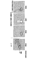
図4は、実施例1の実験系を説明するための概略構成図である。図4に示すように、音響化学治療装置1は、診断用プローブ2、治療用基本波送信トランスデューサ31および治療用第二高調波送信トランスデューサ32、装置本体4、表示手段5から構成される。
装置本体4の内部構成は、本実施形態と同様であるので説明を省略する。
FIG. 4 is a schematic configuration diagram for explaining the experimental system of Example 1. As shown in FIG. 4, the sonochemical treatment device 1 includes a
Since the internal configuration of the apparatus main body 4 is the same as that of this embodiment, the description thereof is omitted.
被検体として、雄のCDF1マウス(以下「マウス」という)10を用いた。マウス実験腫瘍“colon26”26の1mm角の微小切片を5週齢のマウス10の左大腿部に皮下移植し、移植した腫瘍26が直径1cm程度に成長したところで実験に供した。
As a subject, a male CDF 1 mouse (hereinafter referred to as “mouse”) 10 was used. Mouse Experimental Tumor “
図5は、本実施例1で用いた音響化学薬剤である腫瘍集積性ローズベンガル誘導体の構造式である。この薬剤の10mg/ml PBS溶液をマウス10の尾静脈から投与した。投与量は30mg/kgとした。 FIG. 5 is a structural formula of a tumor-accumulating rose bengal derivative which is a sonochemical agent used in Example 1. A 10 mg / ml PBS solution of this drug was administered from the tail vein of mouse 10. The dose was 30 mg / kg.
薬剤を投与して24時間後、ネンブタールを用いてマウス10を麻酔下とし、腫瘍26近傍を剃毛し、窓付きのアクリル板の窓部分に腫瘍26が位置するように手足を固定した。アクリル板を3軸ステージに固定し、図4に示すように、マウス10をアクリル板ごと水槽11中の脱気水12に沈めた。なお、脱気水12は連続的に脱気され、温度は30℃に保たれた。そして、治療用トランスデューサ3と、診断用プローブ2を水槽11中に固定した。治療用トランスデューサ3の焦点である6cmの位置にマウス10の腫瘍26が位置するように、3軸ステージによってマウス10を移動した。
Twenty-four hours after administration of the drug, the mouse 10 was anesthetized using Nembutal, the vicinity of the
図6は、実施例1において治療用トランスデューサから照射した治療用の超音波の形状を示す図である。図6に示すように、治療用の超音波を2s700msのパルス幅で照射し、300ms中断するパルスシーケンスにて治療用トランスデューサ3から超音波を照射した。照射した治療用の超音波の周波数は0.5MHz(パルス数:1350)と1.0MHz(パルス数:2700)とし、併せて200W/cm2の音響強度とした。治療用トランスデューサ3からの治療用の超音波の照射は、診断用プローブ2から照射される診断用の超音波と同期を取った。治療用の超音波として1分間の照射を行い、そのパルスの休止期間に生成された診断画像上の輝度の変化を表示手段5で観察した。なお、本実施例1においては、0.5MHzと1.0MHzの周波数の超音波を0.5+0.5の音響強度(つまり、1:1)の割合で重畳したが、0.1+0.9〜0.9+0.1(つまり、1:9〜9:1)の割合でも構わない。
FIG. 6 is a diagram showing the shape of therapeutic ultrasonic waves irradiated from the therapeutic transducer in the first embodiment. As shown in FIG. 6, therapeutic ultrasonic waves were irradiated with a pulse width of 2 s 700 ms, and ultrasonic waves were irradiated from the therapeutic transducer 3 in a pulse sequence interrupted for 300 ms. The frequency of the irradiated therapeutic ultrasonic waves was 0.5 MHz (number of pulses: 1350) and 1.0 MHz (number of pulses: 2700), and the acoustic intensity was 200 W / cm 2 . Irradiation of therapeutic ultrasonic waves from the therapeutic transducer 3 was synchronized with diagnostic ultrasonic waves irradiated from the
図7は、実施例1において表示手段5に表示された診断画像である。図7に示す一番左の診断画像は、非線形成分を強調する撮像方式と対比するために一般的な超音波診断装置で用いられるBモードで描画したものであって、腫瘍26が認識できる。右3つの診断画像は非線形成分を強調する撮像方式により描画したもので、線形成分を多く含む腫瘍26からの信号はほとんど打ち消され可視化されない。図7に示す非線形成分を強調する撮像方式で描画した診断画像のうち、左からそれぞれ、治療用の超音波パルスの照射前(左2)、照射中(左3)、照射後(左4)を示している。照射中(左3)の図では、照射中の治療の超音波パルスが描画され、気泡に対応する輝度の変化を観察することができないが、超音波パルス照射後(左4)の診断画像においては、治療用の超音波の焦点27に輝度変化が観察できた。超音波を照射して2日後にマウス10を安楽死させ、腫瘍26を取り出してホルマリンで固定後にマウス腫瘍切片を作成し、実際に腫瘍26を観察することによって治療効果を判定した。
FIG. 7 is a diagnostic image displayed on the display unit 5 in the first embodiment. The leftmost diagnostic image shown in FIG. 7 is drawn in the B mode used in a general ultrasonic diagnostic apparatus for comparison with an imaging method that emphasizes a nonlinear component, and the
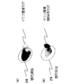
図8は、マウス腫瘍切片を示す図であって、(a)は未処理の腫瘍切片、(b)はHE(Hematoxylin−Eosin)染色処理をした腫瘍切片を示す。図8(a)に示すように、未処理のマウス腫瘍切片において、壊死領域28が明らかに観察された。また、図8(b)に示すように、マウス腫瘍HE染色切片中において、前記した壊死領域28は、Hematoxylin特有の染色が他の部分と比較すると薄く、核の消失や濃縮等の何らかのダメージが生じていることが示された。
FIG. 8 is a view showing a mouse tumor section, in which (a) shows an untreated tumor section and (b) shows a tumor section subjected to HE (Hematoxylin-Eosin) staining treatment. As shown in FIG. 8 (a), a
図9は、治療中に診断画像上での輝度変化が認められた群と、腫瘍切片での観察により治療効果のあった群との相関を示す図である。図9に示すように、診断画像上で輝度変化が観察された場合(モニタリングが○)、3例中3例とも腫瘍切片に壊死領域が観察され、治療効果が見られた。一方で、診断画像上で輝度変化が観察されなかった場合(モニタリングが×)、3例中2例は腫瘍切片に治療効果が見られなかった。ただし、1例は壊死領域が観察され、治療効果が見られた。輝度変化が観察されない場合でも、治療効果が得られる場合もあるが、輝度変化が得られた場合は確実に治療効果が得られることが示された。
換言すると、本発明の音響化学治療装置を用いて治療中に輝度変化をモニタリングできた群は、数日後に実際に腫瘍切片を観察することによって治療効果が認められた群と、明らかに相関があることが示された。
FIG. 9 is a diagram showing a correlation between a group in which a luminance change is observed on a diagnostic image during treatment and a group that has a therapeutic effect by observation on a tumor section. As shown in FIG. 9, when a change in luminance was observed on the diagnostic image (monitoring was ◯), a necrotic area was observed in the tumor sections in three of the three cases, and a therapeutic effect was seen. On the other hand, when no change in luminance was observed on the diagnostic image (monitoring x), 2 of 3 cases showed no therapeutic effect on tumor sections. However, in one case, a necrotic area was observed and a therapeutic effect was seen. Even when the luminance change is not observed, a therapeutic effect may be obtained, but when the luminance change is obtained, the therapeutic effect is surely obtained.
In other words, the group that was able to monitor the change in luminance during treatment using the sonochemical treatment apparatus of the present invention clearly correlated with the group that was observed to have a therapeutic effect by actually observing the tumor section several days later. It was shown that there is.
なお、実施例1と同様の実験系において、0.5MHzと1.0MHzの周波数の超音波を重畳させて、併せて60W/cm2程度の低い音響強度で2分間照射した場合には、治療中の輝度変化のモニタリングができなかった。 In the same experimental system as in Example 1, when ultrasonic waves with frequencies of 0.5 MHz and 1.0 MHz are superimposed and irradiated at a low acoustic intensity of about 60 W / cm 2 for 2 minutes, treatment is performed. The change in brightness could not be monitored.
<実施例2>
実施例2は、治療用の超音波パルスを照射し、診断画像上で気泡が検出された後に、治療用の超音波パルスの音響強度を低下させた場合である。
<Example 2>
Example 2 is a case where the acoustic intensity of the therapeutic ultrasonic pulse is lowered after the therapeutic ultrasonic pulse is irradiated and the bubbles are detected on the diagnostic image.
図10は、実施例2において治療用トランスデューサから照射した治療用の超音波の形状を示す図である。図10に示すように、治療用の超音波を2s700msのパルス幅で照射し、30ms中断するパルスシーケンスにて治療用トランスデューサ3で超音波を照射した。照射した治療用の超音波の周波数は0.5MHz(パルス数:1350)と1.0MHz(パルス数:2700)であった。実施例2においては、図10に示すように、まず、第一の超音波(図10において、High)として、併せて200W/cm2の高い音響強度で3パルスの照射を行い、その後、第二の超音波(図10において、Low)として、併せて60W/cm2の低い音響強度で1分間照射を行った。なお本実施例2においては、0.5MHzと1.0MHzの周波数の超音波を0.5+0.5の音響強度(つまり、1:1)の割合で重畳したが、0.1+0.9〜0.9+0.1(つまり、1:9〜9:1)の割合でも構わない。
そして、超音波のパルスの休止期間に生成された診断画像上の輝度の変化を、表示手段5で観察した。超音波を照射して2日後にマウス10を安楽死させ、腫瘍26を取り出してホルマリンで固定後にマウス腫瘍切片を作成し、実際に腫瘍26を観察することによって治療効果を判定した。
FIG. 10 is a diagram illustrating the shape of therapeutic ultrasonic waves irradiated from the therapeutic transducer in the second embodiment. As shown in FIG. 10, therapeutic ultrasonic waves were irradiated with a pulse width of 2 s 700 ms, and ultrasonic waves were irradiated with the therapeutic transducer 3 in a pulse sequence interrupted for 30 ms. The frequency of the irradiated therapeutic ultrasound was 0.5 MHz (number of pulses: 1350) and 1.0 MHz (number of pulses: 2700). In Example 2, as shown in FIG. 10, first, as the first ultrasonic wave (High in FIG. 10), three pulses are irradiated with a high acoustic intensity of 200 W / cm 2 , and then Two ultrasonic waves (Low in FIG. 10) were irradiated at a low acoustic intensity of 60 W / cm 2 for 1 minute. In the second embodiment, the ultrasonic waves having the frequencies of 0.5 MHz and 1.0 MHz are superimposed at a ratio of the acoustic intensity of 0.5 + 0.5 (that is, 1: 1), but 0.1 + 0.9-0 .9 + 0.1 (ie, 1: 9 to 9: 1) may be used.
And the change of the brightness | luminance on the diagnostic image produced | generated in the idle period of the ultrasonic pulse was observed with the display means 5. FIG. Two days after the irradiation with ultrasound, the mouse 10 was euthanized, the
図11は、治療中に診断画像上での輝度変化が認められた群と、腫瘍切片での観察により治療効果のあった群との相関を示す図である。
第一および第二の超音波を照射中に継続して診断画像上で輝度変化が観察された場合(モニタリングが○)、5例中5例とも腫瘍切片に壊死領域が観察され、治療効果が見られた。
一方で、第一および第二の超音波を照射中に診断画像上で輝度変化が観察されなかった、または、途中で観察されなくなった場合(モニタリングが×)、3例中2例は腫瘍切片に治療効果が見られなかった。ただし、1例は壊死領域が観察され、治療効果が見られた。輝度変化が観察されない場合でも、治療効果が得られる場合もあるが、輝度変化が得られた場合は確実に治療効果が得られることが示された。
FIG. 11 is a diagram showing a correlation between a group in which a luminance change is observed on a diagnostic image during treatment and a group that has a therapeutic effect by observation on a tumor section.
When a change in luminance is observed on the diagnostic image continuously during the irradiation of the first and second ultrasonic waves (monitoring is ◯), necrotic areas are observed in the tumor sections in all 5 cases, and the therapeutic effect is improved. It was seen.
On the other hand, when no change in luminance was observed on the diagnostic image during the irradiation of the first and second ultrasonic waves, or no longer observed on the way (monitoring x), 2 out of 3 cases were tumor sections There was no therapeutic effect. However, in one case, a necrotic area was observed and a therapeutic effect was seen. Even when the luminance change is not observed, a therapeutic effect may be obtained, but when the luminance change is obtained, the therapeutic effect is surely obtained.
実施例1および実施例2の結果から、200W/cm2の音響強度で診断画像上で輝度変化が観察された場合には、全例において治療効果が得られることが示された。さらに、一旦気泡が検出されると、治療用の超音波の音響強度を低下させても診断画像上で輝度の変化が適切にモニタリングされている限り、腫瘍切片の観察によっても治療効果が認められた。 From the results of Example 1 and Example 2, it was shown that when a change in luminance was observed on a diagnostic image with an acoustic intensity of 200 W / cm 2 , a therapeutic effect was obtained in all cases. In addition, once air bubbles are detected, the therapeutic effect is also observed by observing the tumor slice as long as the change in brightness is properly monitored on the diagnostic image, even if the acoustic intensity of the therapeutic ultrasound is reduced. It was.
以上の実施例によれば、本発明の音響化学治療装置を用いて治療中の診断画像上の輝度変化を指標にすることで、音響化学治療が確実に行えていることを確認できることが明確に示された。 According to the above embodiment, it is clearly possible to confirm that the sonochemical treatment can be surely performed by using the change in luminance on the diagnostic image during the treatment as an index using the sonochemical treatment apparatus of the present invention. Indicated.
1 音響化学治療装置
2 診断用プローブ(第1の超音波照射手段、エコー検出手段)
3 治療用トランスデューサ(第2の超音波照射手段)
4 装置本体
5 表示手段
6 被検体
7 対象部位
8 マッチング層
10 マウス
26 腫瘍
31 治療用基本波送信トランスデューサ
32 治療用第二高調波送信トランスデューサ
42 診断用制御部
43 治療用制御部
44 診断画像処理部
431 パルス生成手段(パルス制御手段)
432 増幅手段
433 位相変調手段
441 診断画像生成手段
442 診断画像分析手段
443 診断画像表示手段
DESCRIPTION OF SYMBOLS 1
3 Treatment transducer (second ultrasonic irradiation means)
DESCRIPTION OF SYMBOLS 4 Apparatus main body 5 Display means 6
432 Amplifying means 433 Phase modulating means 441 Diagnostic image generating means 442 Diagnostic image analyzing means 443 Diagnostic image displaying means
Claims (8)
治療用の超音波を照射する第2の超音波照射手段と、
超音波エコーを検出するエコー検出手段と、
前記第1の超音波照射手段を介して前記診断用の超音波を照射し、前記エコー検出手段を介して前記診断用の超音波に対応する前記超音波エコーを検出する診断用制御手段と、
検出された前記超音波エコーに基づいて診断画像を生成する診断画像生成手段と、
前記第2の超音波照射手段を介して前記治療用の超音波を照射する治療用制御手段と、
を備えた音響化学治療装置であって、
生成された前記診断画像に基づいてキャビテーションに関連する気泡を検出する診断画像分析手段を備え、
前記治療用制御手段は、
前記第2の超音波照射手段を介した前記治療用の超音波を、所定のパルス数および休止期間で照射する制御を行うパルス制御手段と、
前記気泡が検出された場合には前記治療用の超音波の音響強度を低下させ、前記気泡が検出されない場合には前記治療用の超音波の音響強度を増加させる増幅手段と、を含み、
前記診断画像生成手段は、
前記治療用の超音波の前記休止期間における前記超音波エコーに基づいて前記診断画像を生成する
ことを特徴とする音響化学治療装置。 First ultrasonic irradiation means for irradiating diagnostic ultrasonic waves;
A second ultrasonic irradiation means for irradiating therapeutic ultrasonic waves;
Echo detection means for detecting ultrasonic echoes;
A diagnostic control means for detecting the ultrasonic echo of the first through the ultrasonic wave irradiation means irradiates the ultrasonic waves for the diagnosis, corresponding to the ultrasound for the diagnosis through the echo detecting means,
Diagnostic image generating means for generating a diagnostic image based on the detected ultrasonic echo;
Therapeutic control means for irradiating the therapeutic ultrasonic waves via the second ultrasonic irradiation means;
A sonochemical treatment apparatus comprising:
Diagnostic image analysis means for detecting bubbles associated with cavitation based on the generated diagnostic image,
The therapeutic control means,
Pulse control means for performing control to irradiate the therapeutic ultrasonic waves via the second ultrasonic irradiation means with a predetermined number of pulses and a rest period ;
Amplifying means for reducing the acoustic intensity of the therapeutic ultrasonic wave when the bubble is detected, and increasing the acoustic intensity of the therapeutic ultrasonic wave when the bubble is not detected ,
The diagnostic image generating means,
That generates the diagnostic image based on the ultrasound echo in the rest period of the ultrasound for the therapy
A sonochemical treatment device.
前記診断画像上の超音波照射前後の輝度の変化に基づいて前記気泡を検出する The bubble is detected based on a change in luminance before and after ultrasonic irradiation on the diagnostic image.
ことを特徴とする請求項1に記載の音響化学治療装置。 The sonochemical treatment apparatus according to claim 1.
前記パルス数および前記休止期間を前記気泡の成長が継続可能な範囲で制御する
ことを特徴とする請求項1または請求項2に記載の音響化学治療装置。 The therapeutic control means includes
That controls the extent growth that can continue the pulse number and the rest period the bubble
The sonochemical treatment apparatus according to claim 1 or 2 , characterized in that
前記パルス数を3以上、前記休止期間を500ms以下で前記治療用の超音波を照射する制御を行う
ことを特徴とする請求項3に記載の音響化学治療装置。 The therapeutic control means includes
The pulse number of 3 or more, intends row control for irradiating the ultrasonic waves for the treatment of the rest period in 500ms or less
The sonochemical treatment apparatus according to claim 3 .
前記診断画像の輝度変化に対応して前記パルス数および前記休止期間を制御する
ことを特徴とする請求項3に記載の音響化学治療装置。 The therapeutic control means includes
That controls the number of pulses and the quiescent period in response to the brightness change of the diagnostic image
The sonochemical treatment apparatus according to claim 3 .
前記治療用の超音波として、前記気泡が発生可能な音響強度からなる第一の超音波を照射した後に、前記第一の超音波の音響強度より低く、かつ、前記気泡の成長が継続可能な音響強度からなる第二の超音波を照射するように制御する
ことを特徴とする請求項1ないし請求項5のいずれか1項に記載の音響化学治療装置。 The therapeutic control means includes
As the therapeutic ultrasonic wave, after irradiating the first ultrasonic wave having an acoustic intensity capable of generating the bubbles, the ultrasonic wave intensity is lower than that of the first ultrasonic wave, and the bubble growth can be continued. that controls so as to irradiate the second ultrasonic consisting sound intensity
The sonochemical treatment device according to any one of claims 1 to 5, wherein:
ことを特徴とする請求項6に記載の音響化学治療装置。 Acoustic intensity of said first ultrasonic wave, that Do is increased over time until the bubble is detected
The sonochemical treatment apparatus according to claim 6 .
前記第1の超音波照射手段から照射される前記診断用の超音波のパルス数より大である
ことを特徴とする請求項1ないし請求項7のいずれか1項に記載の音響化学治療装置。
The number of pulses of the therapeutic ultrasonic wave irradiated from the second ultrasonic irradiation unit is:
Oh Ru in the first larger than ultrasound pulse number for the diagnosis to be irradiated from the ultrasound irradiation means
The sonochemical treatment device according to any one of claims 1 to 7, wherein the device is a sonochemical treatment device.
Priority Applications (3)
| Application Number | Priority Date | Filing Date | Title |
|---|---|---|---|
| JP2005194238A JP4369907B2 (en) | 2005-07-01 | 2005-07-01 | Sonochemical treatment equipment |
| US11/476,866 US7780598B2 (en) | 2005-07-01 | 2006-06-29 | Sonodynamic treatment apparatus and method of controlling the same |
| CN200610099774A CN100588373C (en) | 2005-07-01 | 2006-06-30 | Sonodynamic treatment apparatus |
Applications Claiming Priority (1)
| Application Number | Priority Date | Filing Date | Title |
|---|---|---|---|
| JP2005194238A JP4369907B2 (en) | 2005-07-01 | 2005-07-01 | Sonochemical treatment equipment |
Publications (3)
| Publication Number | Publication Date |
|---|---|
| JP2007007279A JP2007007279A (en) | 2007-01-18 |
| JP2007007279A5 JP2007007279A5 (en) | 2007-12-27 |
| JP4369907B2 true JP4369907B2 (en) | 2009-11-25 |
Family
ID=37596545
Family Applications (1)
| Application Number | Title | Priority Date | Filing Date |
|---|---|---|---|
| JP2005194238A Active JP4369907B2 (en) | 2005-07-01 | 2005-07-01 | Sonochemical treatment equipment |
Country Status (3)
| Country | Link |
|---|---|
| US (1) | US7780598B2 (en) |
| JP (1) | JP4369907B2 (en) |
| CN (1) | CN100588373C (en) |
Cited By (1)
| Publication number | Priority date | Publication date | Assignee | Title |
|---|---|---|---|---|
| JP2013502246A (en) * | 2009-08-18 | 2013-01-24 | アイ、テック、ケア | Parameters for an ultrasonic device with means for generating a high-density ultrasonic beam |
Families Citing this family (23)
| Publication number | Priority date | Publication date | Assignee | Title |
|---|---|---|---|---|
| US7617005B2 (en) * | 2002-04-08 | 2009-11-10 | Ardian, Inc. | Methods and apparatus for thermally-induced renal neuromodulation |
| US20050283074A1 (en) * | 2004-06-22 | 2005-12-22 | Siemens Medical Solutions Usa, Inc. | Ultrasound feedback for tissue ablation procedures |
| US20090062724A1 (en) * | 2007-08-31 | 2009-03-05 | Rixen Chen | System and apparatus for sonodynamic therapy |
| US20090287205A1 (en) * | 2008-05-16 | 2009-11-19 | Boston Scientific Scimed, Inc. | Systems and methods for preventing tissue popping caused by bubble expansion during tissue ablation |
| GB0820377D0 (en) * | 2008-11-07 | 2008-12-17 | Isis Innovation | Mapping and characterization of cavitation activity |
| CN101530320B (en) * | 2009-03-31 | 2010-11-10 | 西安交通大学 | Real-time extracting device and detection method for focused ultrasonic cavitation and microbubbles thereof |
| WO2010127495A1 (en) * | 2009-05-07 | 2010-11-11 | Li Peng | Pulse ultrasound treatment apparatus |
| WO2011030470A1 (en) * | 2009-09-11 | 2011-03-17 | Olympus Medical Systems Corp. | Treatment apparatus and operation system |
| JP5347064B2 (en) * | 2009-09-18 | 2013-11-20 | オリンパスメディカルシステムズ株式会社 | Treatment apparatus and surgical system |
| JP4734448B2 (en) | 2009-12-04 | 2011-07-27 | 株式会社日立製作所 | Ultrasonic therapy device |
| CN102834068B (en) * | 2010-04-09 | 2015-11-25 | 株式会社日立制作所 | Ultrasonic apparatus for diagnosis and therapy |
| JP5647338B2 (en) * | 2010-05-14 | 2014-12-24 | サバンジ・ウニヴェルシテシSabanci Universitesi | Apparatus for using hydrodynamic cavitation for therapy |
| CN101869486B (en) * | 2010-07-16 | 2012-06-27 | 珠海仁威医疗科技有限公司 | Ultrasonic diagnosis and treatment integrated machine |
| CN105188559B (en) * | 2013-02-28 | 2017-09-22 | 爱飞纽医疗机械贸易有限公司 | Detect the method and ultrasonic medical equipment of cavitation |
| JP2014195581A (en) * | 2013-03-29 | 2014-10-16 | オリンパス株式会社 | Ultrasonic treatment apparatus |
| JP6819012B2 (en) * | 2015-06-03 | 2021-01-27 | モンテフィオーレ メディカル センターMontefiore Medical Center | Low-density focused ultrasound to treat cancer and metastases |
| CN105943087B (en) * | 2016-07-26 | 2019-03-19 | 飞依诺科技(苏州)有限公司 | The image processing method and processing system of ultrasonic microbubble cavitation device |
| CN106730424B (en) | 2016-12-19 | 2018-10-30 | 西安交通大学 | Hundred microsecond pulse ultrasonic tissue of confocal harmonic superposition damages mode control method |
| WO2018158805A1 (en) * | 2017-02-28 | 2018-09-07 | オリンパス株式会社 | Ultrasonic medical apparatus |
| JP7289061B2 (en) * | 2017-06-29 | 2023-06-09 | インサイテック リミテッド | Simulation-based drug treatment planning |
| EP4349401A1 (en) | 2019-02-13 | 2024-04-10 | Alpheus Medical, Inc. | Non-invasive sonodynamic therapy |
| JP2022551875A (en) * | 2019-10-11 | 2022-12-14 | インサイテック・リミテッド | Pretreatment tissue sensitization for focused ultrasound procedures |
| CN113117262B (en) * | 2019-12-30 | 2023-06-02 | 重庆融海超声医学工程研究中心有限公司 | Device for detecting cavitation effect and ultrasonic treatment equipment |
Family Cites Families (9)
| Publication number | Priority date | Publication date | Assignee | Title |
|---|---|---|---|---|
| US4610255A (en) * | 1983-12-02 | 1986-09-09 | Fujitsu Limited | Ultrasonic non-linear parameter measuring system |
| EP0619104B1 (en) * | 1992-09-16 | 2002-03-13 | Hitachi, Ltd. | Ultrasonic irradiation apparatus |
| US5694936A (en) * | 1994-09-17 | 1997-12-09 | Kabushiki Kaisha Toshiba | Ultrasonic apparatus for thermotherapy with variable frequency for suppressing cavitation |
| US5520188A (en) * | 1994-11-02 | 1996-05-28 | Focus Surgery Inc. | Annular array transducer |
| US5558092A (en) * | 1995-06-06 | 1996-09-24 | Imarx Pharmaceutical Corp. | Methods and apparatus for performing diagnostic and therapeutic ultrasound simultaneously |
| US6113558A (en) * | 1997-09-29 | 2000-09-05 | Angiosonics Inc. | Pulsed mode lysis method |
| US6095980A (en) * | 1997-10-02 | 2000-08-01 | Sunnybrook Health Science Centre | Pulse inversion doppler ultrasonic diagnostic imaging |
| JP2000229098A (en) | 1998-12-09 | 2000-08-22 | Toshiba Corp | Ultrasonic therapy instrument |
| SE518763C2 (en) * | 2000-07-17 | 2002-11-19 | Ultrazonix Dnt Ab | Device for non-invasive ultrasound treatment of disk disease |
-
2005
- 2005-07-01 JP JP2005194238A patent/JP4369907B2/en active Active
-
2006
- 2006-06-29 US US11/476,866 patent/US7780598B2/en not_active Expired - Fee Related
- 2006-06-30 CN CN200610099774A patent/CN100588373C/en not_active Expired - Fee Related
Cited By (1)
| Publication number | Priority date | Publication date | Assignee | Title |
|---|---|---|---|---|
| JP2013502246A (en) * | 2009-08-18 | 2013-01-24 | アイ、テック、ケア | Parameters for an ultrasonic device with means for generating a high-density ultrasonic beam |
Also Published As
| Publication number | Publication date |
|---|---|
| JP2007007279A (en) | 2007-01-18 |
| CN100588373C (en) | 2010-02-10 |
| CN1891167A (en) | 2007-01-10 |
| US20070038099A1 (en) | 2007-02-15 |
| US7780598B2 (en) | 2010-08-24 |
Similar Documents
| Publication | Publication Date | Title |
|---|---|---|
| JP4369907B2 (en) | Sonochemical treatment equipment | |
| JP4630127B2 (en) | Ultrasound diagnostic treatment device | |
| JP5451819B2 (en) | Method of using combined imaging and therapy transducers to dissolve clots | |
| US20100069797A1 (en) | Pulsed cavitational ultrasound therapy | |
| JP2007144183A (en) | Ultrasound imaging and treatment system using contrast agent | |
| EP1761173A1 (en) | Enhancement of ultrasonic cavitation | |
| JP4640911B2 (en) | Method and apparatus for improving contrast-to-tissue ratio of ultrasound contrast agent imaging signal | |
| Chen et al. | Harmonic motion imaging for abdominal tumor detection and high-intensity focused ultrasound ablation monitoring: an in vivo feasibility study in a transgenic mouse model of pancreatic cancer | |
| JP2008272367A (en) | Ultrasonic imaging system | |
| JP5161955B2 (en) | Ultrasonic irradiation device | |
| KR20140094956A (en) | Method and apparatus for controlling a n ultrasound system | |
| US20240108368A1 (en) | System and method for comminution of biomineralizations using microbubbles | |
| CN112603466B (en) | Irreversible sonoporation device, apparatus and computer readable storage medium | |
| JP5851127B2 (en) | Ultrasonic irradiation apparatus and method of operating ultrasonic irradiation apparatus | |
| Sutin et al. | Prospective medical applications of nonlinear time reversal acoustics | |
| WO2008097998A1 (en) | Ultrasound method and apparatus for tumor ablation, clot lysis, and imaging | |
| Chen et al. | Harmonic motion imaging in abdominal tumor detection and HIFU ablation monitoring: A feasibility study in a transgenic mouse model of pancreatic cancer | |
| JPH1085217A (en) | Method and device for ultrasonic image pick-up | |
| JP4387947B2 (en) | Ultrasonic therapy device | |
| Zhang et al. | Improved assessment sensitivity of time-varying cavitation events based on wavelet analysis | |
| JP7170359B1 (en) | Ultrasound image processor | |
| Ebbini et al. | Quadratic b-mode and pulse inversion imaging of thermally-induced lesions in vivo | |
| Karaböce et al. | Investigations of viscous heating effect of thermocouples under HIFU applications | |
| Bader et al. | Bader2018 IEEE Trans Med Imaging. pdf | |
| Maleke et al. | 9C-5 2D Simulation of the Harmonic Motion Imaging (HMI) with Experimental Validation |
Legal Events
| Date | Code | Title | Description |
|---|---|---|---|
| A521 | Request for written amendment filed |
Free format text: JAPANESE INTERMEDIATE CODE: A523 Effective date: 20071112 |
|
| A621 | Written request for application examination |
Free format text: JAPANESE INTERMEDIATE CODE: A621 Effective date: 20071112 |
|
| A131 | Notification of reasons for refusal |
Free format text: JAPANESE INTERMEDIATE CODE: A131 Effective date: 20090519 |
|
| A977 | Report on retrieval |
Free format text: JAPANESE INTERMEDIATE CODE: A971007 Effective date: 20090521 |
|
| A521 | Request for written amendment filed |
Free format text: JAPANESE INTERMEDIATE CODE: A523 Effective date: 20090721 |
|
| TRDD | Decision of grant or rejection written | ||
| A01 | Written decision to grant a patent or to grant a registration (utility model) |
Free format text: JAPANESE INTERMEDIATE CODE: A01 Effective date: 20090825 |
|
| A01 | Written decision to grant a patent or to grant a registration (utility model) |
Free format text: JAPANESE INTERMEDIATE CODE: A01 |
|
| A61 | First payment of annual fees (during grant procedure) |
Free format text: JAPANESE INTERMEDIATE CODE: A61 Effective date: 20090828 |
|
| R150 | Certificate of patent or registration of utility model |
Ref document number: 4369907 Country of ref document: JP Free format text: JAPANESE INTERMEDIATE CODE: R150 Free format text: JAPANESE INTERMEDIATE CODE: R150 |
|
| FPAY | Renewal fee payment (event date is renewal date of database) |
Free format text: PAYMENT UNTIL: 20120904 Year of fee payment: 3 |
|
| FPAY | Renewal fee payment (event date is renewal date of database) |
Free format text: PAYMENT UNTIL: 20130904 Year of fee payment: 4 |
|
| S111 | Request for change of ownership or part of ownership |
Free format text: JAPANESE INTERMEDIATE CODE: R313114 |
|
| R350 | Written notification of registration of transfer |
Free format text: JAPANESE INTERMEDIATE CODE: R350 |
|
| S531 | Written request for registration of change of domicile |
Free format text: JAPANESE INTERMEDIATE CODE: R313531 |
|
| R350 | Written notification of registration of transfer |
Free format text: JAPANESE INTERMEDIATE CODE: R350 |
|
| S111 | Request for change of ownership or part of ownership |
Free format text: JAPANESE INTERMEDIATE CODE: R313115 |
|
| R350 | Written notification of registration of transfer |
Free format text: JAPANESE INTERMEDIATE CODE: R350 |
|
| R250 | Receipt of annual fees |
Free format text: JAPANESE INTERMEDIATE CODE: R250 |
|
| R250 | Receipt of annual fees |
Free format text: JAPANESE INTERMEDIATE CODE: R250 |
|
| R250 | Receipt of annual fees |
Free format text: JAPANESE INTERMEDIATE CODE: R250 |
|
| S111 | Request for change of ownership or part of ownership |
Free format text: JAPANESE INTERMEDIATE CODE: R313117 |