JP4367325B2 - Discharge device and inkjet printer - Google Patents
Discharge device and inkjet printer Download PDFInfo
- Publication number
- JP4367325B2 JP4367325B2 JP2004344019A JP2004344019A JP4367325B2 JP 4367325 B2 JP4367325 B2 JP 4367325B2 JP 2004344019 A JP2004344019 A JP 2004344019A JP 2004344019 A JP2004344019 A JP 2004344019A JP 4367325 B2 JP4367325 B2 JP 4367325B2
- Authority
- JP
- Japan
- Prior art keywords
- discharge
- medium
- state
- paper
- recording
- Prior art date
- Legal status (The legal status is an assumption and is not a legal conclusion. Google has not performed a legal analysis and makes no representation as to the accuracy of the status listed.)
- Expired - Fee Related
Links
Images


Classifications
-
- B—PERFORMING OPERATIONS; TRANSPORTING
- B41—PRINTING; LINING MACHINES; TYPEWRITERS; STAMPS
- B41J—TYPEWRITERS; SELECTIVE PRINTING MECHANISMS, i.e. MECHANISMS PRINTING OTHERWISE THAN FROM A FORME; CORRECTION OF TYPOGRAPHICAL ERRORS
- B41J13/00—Devices or arrangements of selective printing mechanisms, e.g. ink-jet printers or thermal printers, specially adapted for supporting or handling copy material in short lengths, e.g. sheets
- B41J13/0009—Devices or arrangements of selective printing mechanisms, e.g. ink-jet printers or thermal printers, specially adapted for supporting or handling copy material in short lengths, e.g. sheets control of the transport of the copy material
- B41J13/0036—Devices or arrangements of selective printing mechanisms, e.g. ink-jet printers or thermal printers, specially adapted for supporting or handling copy material in short lengths, e.g. sheets control of the transport of the copy material in the output section of automatic paper handling systems
-
- B—PERFORMING OPERATIONS; TRANSPORTING
- B41—PRINTING; LINING MACHINES; TYPEWRITERS; STAMPS
- B41J—TYPEWRITERS; SELECTIVE PRINTING MECHANISMS, i.e. MECHANISMS PRINTING OTHERWISE THAN FROM A FORME; CORRECTION OF TYPOGRAPHICAL ERRORS
- B41J13/00—Devices or arrangements of selective printing mechanisms, e.g. ink-jet printers or thermal printers, specially adapted for supporting or handling copy material in short lengths, e.g. sheets
- B41J13/10—Sheet holders, retainers, movable guides, or stationary guides
- B41J13/106—Sheet holders, retainers, movable guides, or stationary guides for the sheet output section
Description
本発明は、被搬送媒体を載置可能な媒体載置部へその被搬送媒体を排出する排出装置、及び、こうした排出装置を備えたインクジェットプリンタに関するものである。 The present invention relates to a discharge device that discharges a medium to be transported to a medium placement section on which the medium to be transported can be placed, and an ink jet printer including such a discharge device.
従来、被搬送媒体を載置可能な媒体載置部へその被搬送媒体を排出する排出装置が知られている。
例えばインクジェットプリンタやレーザプリンタ等の記録装置は、被搬送媒体としての記録紙が積載(堆積)された給紙トレイから記録紙を1枚ずつ記録部へ給紙する給紙動作と、記録部において記録紙に画像を記録する記録動作と、記録紙を載置可能な記録紙載置部を形成する排紙トレイへ、記録部において画像の記録された記録紙を排出する排出動作とを行うように構成されている。
2. Description of the Related Art Conventionally, a discharge device that discharges a medium to be transported to a medium placement unit that can place the medium to be transported is known.
For example, a recording apparatus such as an ink jet printer or a laser printer has a sheet feeding operation for feeding recording sheets one by one from a sheet feeding tray on which recording sheets as a transported medium are stacked (stacked) to the recording unit. A recording operation for recording an image on the recording paper and a discharge operation for discharging the recording paper on which the image is recorded in the recording portion to a paper discharge tray that forms a recording paper placing portion on which the recording paper can be placed. It is configured.
ここで、排紙トレイとしては、大きなサイズの記録紙が排出された場合にも安定して載置可能とするために、記録紙載置部を拡張できるように構成されたものがある。
例えば、特許文献1には、排出された記録紙を載置する排紙トレイの一部に凹部を形成し、この凹部に収納可能な補助トレイを回転移動可能に設けることにより、補助トレイを排紙トレイの凹部に収納した状態と、補助トレイを排紙トレイから張り出させた状態とに切り替え可能とした構成が開示されている。
Here, some paper discharge trays are configured such that the recording paper placement section can be expanded in order to allow stable placement even when a large size recording paper is discharged.
For example, in Patent Document 1, a concave portion is formed in a part of a paper discharge tray on which discharged recording paper is placed, and an auxiliary tray that can be accommodated in the concave portion is provided so as to be rotatable. A configuration is disclosed in which the state can be switched between a state in which the paper tray is housed in a recess and a state in which the auxiliary tray is extended from the paper discharge tray.
また、例えば特許文献2には、排出された記録紙を載置する排紙トレイの一部に凹部を形成し、排紙トレイに対して回転移動可能な拡張トレイと、この拡張トレイに対して更に回転移動可能な補助トレイとを上記凹部に収納可能に設けることにより、排紙トレイに対して拡張トレイを開き、更に拡張トレイに対して補助トレイを開くことにより、記録紙載置部を大幅に拡張できるようにした構成が開示されている。
ところで、記録紙を排紙トレイへ排出する際の記録紙の搬送速度(排出速度)は、高速であるほど記録紙の排出動作に要する時間を短縮することができ、ひいては記録紙への画像の記録処理(給紙動作、記録動作及び排出動作)に要する時間を短縮することができる。このため、記録紙への画像の記録処理に要する時間を短縮するという面では、記録紙の排出速度をできるだけ高速にすることが好ましい。 By the way, as the recording paper transport speed (discharge speed) for discharging the recording paper to the paper discharge tray increases, the time required for the recording paper discharge operation can be shortened. The time required for the recording process (paper feeding operation, recording operation, and discharging operation) can be shortened. For this reason, it is preferable that the discharge speed of the recording paper be as high as possible in terms of shortening the time required for the image recording process on the recording paper.
しかしながら、記録紙の排出速度を高速にするほど、排紙トレイに排出された記録紙の整列性が悪くなる傾向にあり、排紙トレイから記録紙が落下する要因となる。特に、例えばファクシミリ機能を有したものでは、記録紙が排紙トレイから落下すると記録紙の紛失によるトラブルを招くおそれがある。こうした記録紙の落下の問題は、大型の排紙トレイを用いることにより回避することが可能であるが、排紙トレイを大型化することは装置自体の大型化につながるという面で好ましくない。 However, the higher the recording paper discharge speed, the worse the alignment of the recording paper discharged to the paper discharge tray, which causes the recording paper to fall from the paper discharge tray. In particular, for example, a printer having a facsimile function may cause trouble due to loss of the recording paper when the recording paper falls from the paper discharge tray. Such a problem of dropping the recording paper can be avoided by using a large paper discharge tray. However, increasing the paper discharge tray is not preferable in terms of increasing the size of the apparatus itself.
一方、上述のように排紙トレイにより形成される記録紙載置部を拡張可能な構成とすれば、装置自体の大型化を防止することが可能となるが、このような構成では、記録紙載置部を拡張している状態を基準にして記録紙の排出速度を設定すると、記録紙載置部を拡張していない状態において記録紙が落下するという問題が生じ得る。このため、記録紙載置部を拡張していない状態を基準にして記録紙の排出速度を低速に設定せざるを得ず、記録紙の排出動作に要する時間を十分に短縮することができなかった。 On the other hand, if the configuration in which the recording paper placement portion formed by the paper discharge tray can be expanded as described above, the size of the apparatus itself can be prevented from increasing. If the discharge speed of the recording paper is set based on the state where the loading portion is expanded, there may be a problem that the recording paper falls in a state where the recording paper loading portion is not expanded. For this reason, the recording paper discharge speed has to be set to a low speed based on the state in which the recording paper loading section is not expanded, and the time required for the recording paper discharge operation cannot be sufficiently shortened. It was.
本発明は、こうした問題にかんがみてなされたものであり、被搬送媒体の排出に要する時間を短縮することを目的としている。 The present invention has been made in view of these problems, and an object thereof is to shorten the time required for discharging the medium to be transported.
上記目的を達成するためになされた請求項1に記載の排出装置は、被搬送媒体を載置可能な媒体載置部へその被搬送媒体を排出する排出手段と、媒体載置部を形成するとともに、その媒体載置部の状態を、基準状態とこの基準状態に比べ被搬送媒体の排出方向へ拡張された拡張状態とに変更可能に構成された媒体載置手段とを備えている。なお、媒体載置手段としては、例えば、媒体載置部を主として形成する部材とその媒体載置部を拡張するための部材との位置関係を変化させることにより媒体載置部の状態を変更可能にする構成や、伸縮可能な構造により媒体載置部の状態を変更可能にする構成等が考えられる。 The discharge device according to claim 1, which has been made to achieve the above object, forms a discharge unit that discharges the medium to be transported to a medium mounting unit on which the medium to be transported can be mounted, and a medium mounting unit. In addition, there is provided medium placing means configured to be able to change the state of the medium placing portion into a reference state and an expanded state expanded in the discharge direction of the transported medium as compared with the reference state. As the medium loading means, for example, the state of the medium loading portion can be changed by changing the positional relationship between a member mainly forming the medium loading portion and a member for expanding the medium loading portion. A configuration in which the state of the medium placement unit can be changed by an extendable structure or the like can be considered.
さらに、本排出装置は、排出速度制御手段を備えており、この排出速度制御手段が、媒体載置部の状態を判断し、その状態が拡張状態である場合には、基準状態である場合に比べ、排出手段による被搬送媒体の排出速度を速くする。 In addition, the discharge device includes a discharge speed control unit. The discharge speed control unit determines the state of the medium placement unit, and when the state is the expanded state, In comparison, the discharge speed of the transported medium by the discharge means is increased.
つまり、本排出装置は、媒体載置手段により形成される媒体載置部へ被搬送媒体を排出するものであり、媒体載置部の状態が拡張状態である場合には、基準状態である場合よりも高速で被搬送媒体を排出するように構成されている。 In other words, the discharge device discharges the medium to be transported to the medium placement unit formed by the medium placement unit. When the state of the medium placement unit is the expanded state, the reference state is set. It is configured to discharge the transported medium at a higher speed than that.
したがって、本発明の排出装置によれば、被搬送媒体が媒体載置部から落下することを防止しつつ、被搬送媒体の排出に要する時間を短縮することができる。すなわち、媒体載置部の状態に関係なく一定の排出速度で被搬送媒体を排出する構成では、媒体載置部の状態が拡張状態である場合を基準にして排出速度を設定すると、媒体載置部の状態が基準状態である場合に被搬送媒体が落下するという問題が生じ得るため、媒体載置部の状態が基準状態である場合を基準にして排出速度を設定する必要がある。これに対し、本発明の排出装置では、媒体載置部の状態が拡張状態である場合には排出速度を速くすることができる分、被搬送媒体の排出に要する時間を短縮することができるのである。 Therefore, according to the discharge device of the present invention, it is possible to reduce the time required to discharge the transported medium while preventing the transported medium from falling from the medium placement unit. In other words, in a configuration in which the medium to be transported is discharged at a constant discharge speed regardless of the state of the medium placement unit, if the discharge speed is set based on the case where the state of the medium placement unit is the expanded state, the medium placement When the state of the part is the reference state, there may be a problem that the transported medium falls. Therefore, it is necessary to set the discharge speed based on the case where the state of the medium placing part is the reference state. On the other hand, in the discharge device according to the present invention, when the state of the medium mounting portion is in the expanded state, the time required for discharging the medium to be transported can be shortened because the discharge speed can be increased. is there.
しかも、媒体載置部の拡張状態は、基準状態に比べ、媒体載置部が被搬送媒体の排出方向へ延長された状態であるため、被搬送媒体が媒体載置部から落下することを最も効果的に防止することができる。
また、請求項2に記載の排出装置では、上記請求項1に記載の排出装置において、媒体載置手段が、排出トレイと、排出トレイに対する位置を変更可能な補助トレイとを備え、補助トレイを所定の収納位置とすることで媒体載置部が排出トレイのみにより形成される基準状態となり、補助トレイを収納位置よりも被搬送媒体の排出方向側の拡張位置とすることで媒体載置部が排出トレイ及び補助トレイにより形成される拡張状態となるように構成されている。そして、補助トレイは、拡張位置において被搬送媒体の排出方向の下流側がその上流側よりも高くなる傾斜状態となる。 Moreover, the expanded state of the medium placing portion is compared with the criteria state, the medium placing portion is in a state of extending in the ejecting direction of the carrier medium, that the conveyed medium is dropped from the medium placing portion Ru can be most effectively prevented.
The discharge device according to
ところで、媒体載置部の状態は、例えば請求項3や請求項4のように判断することができる。
すなわち、請求項3に記載の排出装置は、上記請求項1又は2の排出装置において、媒体載置部の状態を検知する検知手段を備えており、排出速度制御手段は、検知手段による検知結果に基づき媒体載置部の状態を判断する。この構成によれば、媒体載置部の状態を正確に判断することができる。なお、検知手段としては、周知のセンサ類を用いることができる。
By the way, the state of the medium mounting portion can be determined as in, for example, claims 3 and 4.
That is, the discharge device according to
また、請求項4に記載の排出装置は、上記請求項1又は2の排出装置において、媒体載置部の状態に関する情報が入力される入力手段を備えており、排出速度制御手段は、入力手段に入力された情報に基づき媒体載置部の状態を判断する。この構成によれば、媒体載置部の状態を検知するセンサ等を設けることなく媒体載置部の状態を判断することができる。なお、入力手段は、例えば、使用者からの入力操作に基づく情報が入力されるように構成することができる。 According to a fourth aspect of the present invention, there is provided the discharge device according to the first or second aspect, further comprising an input unit for inputting information relating to the state of the medium placement unit, and the discharge speed control unit includes the input unit. The state of the medium loading unit is determined based on the information input to. According to this configuration, the state of the medium placement unit can be determined without providing a sensor or the like that detects the state of the medium placement unit. The input unit can be configured such that information based on an input operation from the user is input, for example.
一方、請求項5に記載の排出装置では、上記請求項1〜4のいずれかの排出装置において、媒体載置手段が、媒体載置部の状態を、基準状態に対する拡張度合いが異なる複数段階の拡張状態に変更可能に構成されており、排出速度制御手段は、媒体載置部の拡張度合いが大きいほど、排出手段による被搬送媒体の排出速度を速くする。この構成によれば、媒体載置部の状態に応じて被搬送媒体の排出に要する時間を効率よく短縮することができる。なお、ここでいう「基準状態に対する拡張度合いが異なる複数段階の拡張状態に変更可能」な構成とは、3段階、4段階等の段階に限らず、拡張度合いを連続的に変化可能な構成であってもよい。
On the other hand, in the discharge device according to
ところで、本発明の排出装置は、被搬送媒体を排出する様々な用途(例えば、インクジェットプリンタ、レーザプリンタ等の記録装置)に利用可能であるが、特に、請求項6のように構成すると効果的である。 By the way, the discharge device of the present invention can be used for various applications (for example, a recording device such as an ink jet printer, a laser printer, etc.) for discharging a medium to be transported. It is.
すなわち、請求項6に記載のインクジェットプリンタは、上記請求項1〜請求項5のいずれかの排出装置を備え、被搬送媒体として、画像を記録した被記録媒体を排出するように構成されている。なお、ここでいう被記録媒体とは、インクの吐出により画像(文字や記号等も含む。)の記録が可能な媒体を意味しており、例えば、記録紙等のシート体が挙げられる。 That is, an ink jet printer according to a sixth aspect includes the discharge device according to any one of the first to fifth aspects, and is configured to discharge a recording medium on which an image is recorded as a transported medium. . Here, the recording medium means a medium capable of recording an image (including characters and symbols) by ejecting ink, and examples thereof include a sheet body such as recording paper.
一般に、インクジェットプリンタは、被記録媒体への画像の記録動作が完了した時点で被記録媒体の排出動作を行うように構成されており、被記録媒体に記録する画像の割合が低いほど、画像の記録動作に要する時間が短くなる。このため、インクジェットプリンタは、被記録媒体に記録する画像の割合に関係なく画像の記録動作に一定の時間を要するレーザプリンタに比べ、被搬送媒体の排出動作に要する時間を短縮することによる効果(被記録媒体への画像の記録処理に要する時間を短縮する効果)が高い。したがって、本発明のインクジェットプリンタによれば、被記録媒体への画像の記録処理に要する時間を効果的に短縮することができる。 In general, an inkjet printer is configured to perform a discharge operation of a recording medium when an image recording operation on the recording medium is completed. The lower the ratio of images to be recorded on a recording medium, the more the image is recorded. The time required for the recording operation is shortened. For this reason, the ink jet printer has the effect of shortening the time required for the discharge operation of the transported medium as compared with the laser printer that requires a certain time for the image recording operation regardless of the ratio of the image to be recorded on the recording medium ( The effect of shortening the time required for recording the image on the recording medium is high. Therefore, according to the ink jet printer of the present invention, it is possible to effectively shorten the time required for recording an image on a recording medium.
以下、本発明が適用された実施形態について、図面を用いて説明する。
図1は、実施形態の多機能装置(MFD:Multi Function Device)1の斜視図であり、図2は、その側断面図である。
Embodiments to which the present invention is applied will be described below with reference to the drawings.
FIG. 1 is a perspective view of a multi-function device (MFD) 1 according to the embodiment, and FIG. 2 is a side sectional view thereof.
この多機能装置1は、プリンタ機能、コピー機能、スキャナ機能及びファクシミリ機能を有したものであり、図1及び図2に示すように、合成樹脂製のハウジング2の上部に、原稿の読み取りに用いられる画像読取装置12が設けられている。
The multi-function device 1 has a printer function, a copy function, a scanner function, and a facsimile function. As shown in FIGS. 1 and 2, the multi-function device 1 is used for reading an original on a
画像読取装置12は、その左端部に設けられた図示しない枢軸を中心にハウジング2に対して上下開閉回動可能に構成されており、さらに、この画像読取装置12の上面を覆う原稿カバー体13が、その後端部に設けられた枢軸12a(図2参照)を中心に画像読取装置12に対して上下開閉回動可能に装着されている。
The
そして、図2に示すように、画像読取装置12の上面には、原稿カバー体13を上側に開けて読み取り用の原稿を載置するための載置用ガラス板16が設けられ、その下側には、原稿読み取り用の密着型イメージセンサ(CIS:Contact Image Sensor)17が図2の紙面と直交する方向(主走査方向、左右方向)に延びるガイドシャフト44に沿って往復移動可能に設けられている。
As shown in FIG. 2, a
また、図1及び図2に示すように、画像読取装置12の前方には、入力操作を行うための操作ボタン群14aや各種情報を表示するための液晶表示部(LCD)14bを備えた操作パネル部14が設けられている。
As shown in FIGS. 1 and 2, an operation including an
一方、ハウジング2の底部には、被記録媒体(被搬送媒体)としての記録紙Pを給紙するための給紙部11が設けられている。この給紙部11には、記録紙Pを積載(堆積)した状態で収容する給紙カセット3が、ハウジング2の前側に形成された開口部2aを介して、ハウジング2に対し前後方向に着脱可能に設けられている。本実施形態において、給紙カセット3は、A4サイズ、レターサイズ、リーガルサイズ、はがきサイズ等の記録紙Pをその短辺(幅)が給紙方向(副走査方向、前後方向、矢印A方向)と直交する方向(主走査方向、左右方向)に延びる向きで複数枚積載(堆積)して収納可能に構成されている。
On the other hand, at the bottom of the
そして、図2に示すように、給紙カセット3の奥側(後端部側)には、記録紙分離用の傾斜分離板8が配置されている。この傾斜分離板8は、記録紙Pの幅方向(左右方向)中央部において突出し、記録紙Pの幅方向左右両端部側へ向かうに従って後退するように平面視で凸湾曲状に形成されており、記録紙Pの幅方向中央部には、記録紙Pの先端縁に当接して分離を促進するための鋸歯状の弾性分離パッド8a(図5〜図7参照)が設けられている。
As shown in FIG. 2, an
また、給紙部11において、ハウジング2側には、給紙カセット3から記録紙Pを給紙するための給紙アーム6aの基端部が上下方向に回動可能に装着され、この給紙アーム6aの先端部に設けられた給紙ローラ6bには、給紙アーム6a内に設けられた歯車伝達機構6cにより、LF(搬送)モータ132(図9参照)からの回転駆動力が伝達される。そして、この給紙ローラ6bと上述した傾斜分離板8の弾性分離パッド8aとにより、給紙カセット3に堆積された記録紙Pを1枚ずつ分離搬送する。こうして給紙方向(矢印A方向)に沿って進むように分離された記録紙Pは、第1搬送路体60と第2搬送路体52との間隙に形成された横向きU字形状のパスを含む給送路9を介して、給紙カセット3の上方(高い位置)に設けられた記録部7に給送される。
Further, in the
図3は、画像読取装置12を除いた状態での多機能装置1の部分平面図である。
同図に示すように、記録部7は、上向き開放の箱状に形成されたメインフレーム21と、その左右一対の側板21aによって支持され左右方向(主走査方向)に延びる横長の板状の第1ガイド部材22及び第2ガイド部材23との間に設けられており、下面からインクを吐出することで記録紙Pに画像を記録するインクジェット式の記録ヘッド4(図2参照)と、この記録ヘッド4が搭載されたキャリッジ5とを備えている。
FIG. 3 is a partial plan view of the multi-function device 1 with the
As shown in the figure, the
キャリッジ5は、排紙方向(矢印B方向)上流側の第1ガイド部材22及び下流側の第2ガイド部材23にまたがって摺動自在に支持されており、左右方向に往復移動可能となっている。そして、排紙方向(矢印B方向)下流側に配置された第2ガイド部材23の上面には、キャリッジ5を往復移動させるために、主走査方向(左右方向)に延びるようにタイミングベルト24が巻回されており、このタイミングベルト24を駆動するCR(キャリッジ)モータ131(図9参照)が、第2ガイド部材23の下面に固定されている。
The
一方、記録部7において、キャリッジ5における記録ヘッド4の下面には、記録ヘッド4と対向して左右方向に延びる扁平状のプラテン26が、上記両ガイド部材22,23の間にて、メインフレーム21に固定されている。
On the other hand, in the
そして、図2に示すように、プラテン26の排紙方向(矢印B方向)上流側には、記録紙Pを記録ヘッド4の下面に搬送するための搬送(レジスト)ローラとして、駆動ローラ50と、この駆動ローラ50に対向する下方にニップローラ51とが配置されている。また、プラテン26の排紙方向(矢印B方向)下流側には、記録部7を経た記録紙Pを排紙方向(矢印B方向)に沿って排紙部10に搬送するように駆動される排紙ローラ28と、これに対向して排紙ローラ28側に付勢された拍車ローラ(図示せず)とが配置されている。
As shown in FIG. 2, on the upstream side of the
記録部7にて記録された記録紙Pがその記録面を上向きにして排出される排紙部10は、給紙部11の上方に配置され、排紙口10aがハウジング2の前面の開口部2aと共通にして開口されている。そして、排紙部10から排紙方向(矢印B方向)に従って排出された記録紙Pは、開口部2aの内部側に位置する排紙トレイ10b上に堆積収容される。
The
なお、画像読取装置12によって覆われたハウジング2の前部右端位置には、図示しないインク貯蔵部が設けられている。このインク貯蔵部には、フルカラー記録のための4色(ブラック(Bk)、シアン(C)、マゼンタ(M)、イエロー(Y))のインクをそれぞれ収容した4つのインクカートリッジが、画像読取装置12を上方に開いた状態で着脱可能となるように装着されている。そして、各色のインクカートリッジと上述した記録ヘッド4とは、可撓性を有する4本のインク供給管で連結されており、各インクカートリッジに収容されたインクは、各インク供給管を介して記録ヘッド4へ供給される。
An ink storage unit (not shown) is provided at the front right end position of the
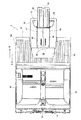
次に給紙カセット3について詳細に説明する。
図4は、給紙カセット3の斜視図であり、図5は、その平面図であり、図6は、後述する補助支持部材33が引き出された状態での給紙カセット3の斜視図であり、図7は、給紙カセット3の側断面図である。なお、図7(a)は、図6(a)のC−C断面図である。
Next, the
4 is a perspective view of the
図4〜図7に示すように、給紙カセット3には、記録紙Pを載置する底板31が設けられ、この底板31における給紙方向(矢印A方向)上流側には、給紙方向に沿う両側部に側板32,32が立設されている。そして、記録部7から排出された記録紙Pを載置可能な記録紙載置部(媒体載置部に相当)を形成するための排紙トレイ10bが、底板31に載置された記録紙Pの給紙方向(矢印A方向)上流側の一部を覆うように、両側板32、32にまたがって着脱可能に取り付けられている。この排紙トレイ10bの排紙方向(矢印B方向)の下流側端部には、底板31上へ記録紙Pを補給しやすくするために、幅方向の中央部に、平面視略コ字状の切欠部43が形成されている。
As shown in FIGS. 4 to 7, the
また、底板31における給紙方向(矢印A方向)下流側には、記録紙Pを給紙カセット3の幅方向の中心に対して左右対称にセットするための記録紙幅ガイド45が左右方向(幅方向)に伸縮するように移動可能に設けられている。
In addition, on the downstream side of the
さらに、底板31の給紙方向(矢印A方向)上流側端部における幅方向の中央部には、この上流側端部から更に外方(排紙方向の更に下流側)へスライド可能に、略長方形板状の補助支持部材33が設けられている。そして、底板31には、補助支持部材33の給紙方向(矢印A方向)に沿った両側部をスライド可能に挟持するとともに、補助支持部材33を収納可能な第1収納部39が形成されている(図5及び図6参照)。
Further, at the central portion in the width direction at the upstream end portion of the
また、補助支持部材33には、これをスライド移動させる際にユーザが把持しやすいように、把持用開口部42が給紙方向(矢印A方向)上流側端部に板面を貫通して形成されている。
The
さらに、この補助支持部材33には、排紙補助トレイ35が取り付けられている。この排紙補助トレイ35は、排紙トレイ10bにより形成される記録紙載置部を記録紙Pの排出方向(矢印B方向)へ拡張(延長)するためのものである(図2参照)。
Further, a discharge assist
すなわち、補助支持部材33の上面には、排紙補助トレイ35を収納するための凹部として、第2収納部34が形成されている。そして、排紙補助トレイ35は、第2収納部34に収納される収納位置(図4、図6(b)及び図7(b)参照)と、底板31の給紙方向(矢印A方向)上流側端部よりも排紙方向(矢印B方向)へ延びる拡張位置(図2、図5、図6(a)及び図7(a)参照)との間で回転移動可能に構成されており、拡張位置にあるときに、外方へ突出した記録紙Pを支持する。つまり、排紙補助トレイ35を収納位置とすることで、記録紙載置部が排紙トレイ10bのみにより形成される基準状態となり、排紙補助トレイ35を拡張位置とすることで、記録紙載置部が排紙トレイ10bと排紙補助トレイ35とにより形成される拡張状態となる。このように、排紙補助トレイ35の位置を変えることにより、記録紙載置部の状態を変更可能に構成されている。
That is, a
また、第2収納部34の底面には、わずかに上方へ突出したリブ36,36が形成されており(図5及び図6(a)参照)、排紙補助トレイ35が収納された状態でその排紙補助トレイ35の下面に当接することで、第2収納部34の両側端部に設けられたリブ40,40と、排紙補助トレイ35の両側端に設けられたリブ47,47とが、面一となるように構成されている(図6(b)参照)。
Further,
一方、排紙補助トレイ35は、その拡張位置では、補助支持部材33の把持用開口部42における給紙方向(矢印A方向)上流側の内側部に当接することで、排紙方向(矢印B方向)の下流側が上流側より高くなる傾斜状態が維持される(図2、図6(a)及び図7(a)参照)。この傾斜状態により、上方に位置する排紙トレイ10bから突出した記録紙Pの端部を受け止めやすくなっている。しかも、把持用開口部42の内側部が、排紙補助トレイ35の傾斜状態の保持に利用されるので、上記傾斜状態を保持するための特別な構造の付加が不要となる。なお、排紙補助トレイ35の回転軸となる枢軸38(図5、図7参照)から遠い側の端部には、排紙補助トレイ35を回動させる際に、これをつまみやすくするために、回動用切欠部46が設けられている(図5及び図6参照)。
On the other hand, in the extended position, the discharge
また、本実施形態の多機能装置1は、排紙補助トレイ35の位置を検知可能に構成されている。
図8は、排紙補助トレイ35の位置を検知する構成を説明するための説明図である。具体的には、(a)は、補助支持部材33及び排紙補助トレイ35が収納された状態での給紙カセット3の模式的な断面図であり、(b)は、(a)の状態から補助支持部材33が引き出された状態での給紙カセット3の模式的な断面図であり、(c)は、(b)の状態から排紙補助トレイ35が拡張位置へ回転移動された状態での給紙カセット3の模式的な断面図である。
Further, the multi-function device 1 of the present embodiment is configured to be able to detect the position of the paper discharge
FIG. 8 is an explanatory diagram for describing a configuration for detecting the position of the discharge
同図に示すように、給紙カセット3の下部には、排紙補助トレイ35の位置を検知するための補助トレイセンサ(スイッチ)112が設けられている。この補助トレイセンサ112は、主走査方向に延びる回転軸112bを中心に揺動可能な板状の突出片112aを備えており、この突出片112aが補助トレイセンサ112本体側(図8でいう下側)に押し込まれている状態でオンし、突出片112aが押し込まれていない状態でオフする構成のものである。
As shown in the figure, an auxiliary tray sensor (switch) 112 for detecting the position of the paper discharge
一方、給紙カセット3の底板31には長孔状の貫通孔31aが設けられており、また、補助支持部材33には本補助支持部材33の引き出し方向に沿った直線状の貫通孔37(図5、図6(a)参照)が設けられており、底板31の貫通孔31aと補助支持部材33の貫通孔37とは、補助支持部材33の引き出し位置に関係なく連通するように構成されている。そして、補助トレイセンサ112の突出片112aは、貫通孔31a及び貫通孔37を貫通した状態で、排紙補助トレイ35に直接接触するようになっている。このような構成により、排紙補助トレイ35が収納位置の状態では(図8(a),(b))、排紙補助トレイ35により突出片112aが補助トレイセンサ112本体側に押し込まれ、補助トレイセンサ112がオン状態となる。一方、排紙補助トレイ35が拡張位置の状態では(図8(c))、排紙補助トレイ35により突出片112aが押し込まれないため、補助トレイセンサ112がオフ状態となる。このため、本多機能装置1では、補助トレイセンサ112による検知結果に基づき、排紙補助トレイ35の位置(換言すれば、記録紙載置部の状態)を判断することができる。
On the other hand, the
なお、突出片112aは、補助トレイセンサ112本体側に押し込まれることによりその補助トレイセンサ112本体内に完全に収納される位置まで移動可能に構成されている。このため、給紙カセット3の着脱時には、突出片112aが補助トレイセンサ112本体内に押し込まれて収納されることとなり、着脱が阻害されない。
The protruding
次に、本実施形態の多機能装置1の制御系の構成について説明する。
図9は、多機能装置1の制御系の構成を表すブロック図である。
同図に示すように、この制御系は、CPU101、ROM102、RAM103、EEPROM104、及び、これらを接続するバス105からなるマイクロコンピュータを中心に構成されている。また、バス105には、各種センサからの情報を取り込み、そのデータを高速に処理するとともに、各種アクチュエータを駆動制御するためのASIC(Application Specific Integrated Circuit)110が接続されている。
Next, the configuration of the control system of the multi-function device 1 of the present embodiment will be described.
FIG. 9 is a block diagram illustrating a configuration of a control system of the multi-function device 1.
As shown in the figure, this control system is mainly composed of a microcomputer comprising a
そして、ASIC110には、給紙された記録紙Pの位置を検知するためのレジセンサ111、排紙補助トレイ35の位置を検知するための補助トレイセンサ112、駆動ローラ50の回転量を検知するためのロータリエンコーダ113、キャリッジ5の移動量を検知するためのリニアエンコーダ114が接続されている。
The
また、ASIC110には、記録ヘッド4から所定のタイミングでインクを記録紙Pに対して選択的に吐出させるための駆動回路121と、CRモータ131を駆動することにより、記録ヘッド4が搭載されたキャリッジ5を主走査方向(左右方向)に移動させるための駆動回路122と、上述した給紙ローラ6b、駆動ローラ50及び排紙ローラ28を回転駆動する駆動源となるLFモータ132を駆動することにより、記録紙Pを搬送するための駆動回路123とが接続されている。
The
ここで、給紙ローラ6b、駆動ローラ50及び排紙ローラ28は、LFモータ132からの回転駆動力が伝達されることにより一斉に回転するが、給紙ローラ6bが給紙カセット3から記録紙Pを給紙する方向に回転している状態では、駆動ローラ50及び排紙ローラ28は、記録紙Pを排紙側へ搬送する方向(以下「搬送回転方向」という。)とは逆方向に回転するように構成されており、LFモータ132の回転方向を逆転することにより、駆動ローラ50及び排紙ローラ28が搬送回転方向に回転するように構成されている。つまり、給紙ローラ6bの回転によって給紙カセット3から記録紙Pが給紙される状態においては、駆動ローラ50が搬送回転方向とは逆方向に回転しており、これにより給紙カセット3から給紙された記録紙Pの先端が駆動ローラ50及びニップローラ51からなる搬送(レジスト)ローラに当接してその斜行が矯正されることとなる。さらに、LFモータ132から給紙ローラ6bへの回転駆動力伝達経路は、回転駆動力を伝達する伝達状態と、回転駆動力を伝達しない非伝達状態とに切り替え可能に構成されており、LFモータ132から給紙ローラ6bへは、記録紙Pの給紙動作を行う場合にのみ回転駆動力が伝達される。
Here, the
一方、ASIC110には、上述した密着型イメージセンサ(CIS)17が接続されており、密着型イメージセンサ17により読み取られた原稿の画像データが入力される。
さらに、ASIC110には、操作パネル部14の操作ボタン群14aでの入力操作により入力される使用者からの情報をASIC110へ入力し、ASIC110からの表示指令に従い操作パネル部14の液晶表示部14bに各種メッセージ等を表示するためのパネルインターフェイス(パネルI/F)124が接続されている。
On the other hand, the above-described contact image sensor (CIS) 17 is connected to the
Further, information from a user input by an input operation using the
加えて、ASIC110には、図示しないパーソナルコンピュータなどの外部機器とパラレルケーブルやUSBケーブルを介して通信を行うためのパラレルインターフェイス(パラレルI/F)125やUSBインターフェイス(USBI/F)126、PSTN(公衆交換電話網)を介して通信を行うためのNCU(Network Control Unit)127等も接続されている。また、NCU127には、PSTNからNCU127に入力された通信信号を復調するとともに、NCU127からファクシミリ送信等で外部へ送信するデータを通信信号に変調するためのモデム128が接続されている。
In addition, the
このように構成された本実施形態の多機能装置1においては、CPU101及びASIC110の動作によって、プリンタ機能、コピー機能、スキャナ機能及びファクシミリ機能が実現される。
In the multi-function device 1 of this embodiment configured as described above, a printer function, a copy function, a scanner function, and a facsimile function are realized by the operations of the
例えば、プリンタ機能、コピー機能及びファクシミリ機能において、記録紙Pに画像を記録する場合には、まず、LFモータ132を駆動することにより給紙ローラ6bを回転させ、給紙カセット3から記録紙Pを給紙する。このとき、駆動ローラ50及び排紙ローラ28は搬送回転方向とは逆方向に回転しており、給紙ローラ6bによって搬送された記録紙Pの先端が駆動ローラ50及びニップローラ51からなる搬送(レジスト)ローラに当接してその斜行が矯正される。続いて、LFモータ132から給紙ローラ6bへの回転駆動力伝達経路を非伝達状態として給紙ローラ6bの回転を停止させ、更にLFモータ132の回転を逆方向に切り替えて駆動ローラ50及び排紙ローラ28を搬送回転方向に回転させることによって、記録紙Pを記録部7へ給紙する。こうして記録部7へ給紙された記録紙Pに対し、記録ヘッド4が搭載されたキャリッジ5を主走査方向(左右方向)に移動させつつ記録ヘッド4からインクを吐出する動作と、その記録紙Pを所定量搬送する動作とを交互に繰り返すことにより、画像データの表す画像を記録する。そして、記録紙Pへの画像の記録が完了すると、排紙ローラ28の回転により記録紙Pを排紙トレイ10bへ排出する。
For example, when an image is recorded on the recording paper P in the printer function, copy function, and facsimile function, first, the
ところで、記録紙Pを排紙ローラ28により排紙トレイ10bへ排出する際の記録紙Pの搬送速度(排出速度)は、記録紙Pへの画像の記録処理に要する時間を短縮するという面では、できるだけ高速にすることが好ましいが、記録紙Pの排出速度を高速にするほど排紙トレイ10bに排出された記録紙Pの整列性が悪くなる傾向にあり、排紙トレイ10bから記録紙Pが落下するという問題が生じ得るため、従来のこの種のプリンタでは、排紙補助トレイ35が収納位置の状態を基準にして記録紙Pの排出速度が低めに設定されていた。しかしながら、排紙補助トレイ35が拡張位置の状態においてまで低い排出速度で記録紙Pを排出することは、記録紙Pへの画像の記録処理に要する時間が長くなる要因となる。
By the way, the conveyance speed (discharge speed) of the recording paper P when the recording paper P is discharged to the
そこで、本実施形態の多機能装置1では、排紙補助トレイ35の位置に応じて記録紙Pの排出速度を変えることにより、記録紙Pが排紙トレイ10bから落下することを防止しつつ、記録紙Pへの画像の記録処理に要する時間の短縮を図るようにしている。
Therefore, in the multi-function device 1 of the present embodiment, by changing the discharge speed of the recording paper P according to the position of the discharge
以下、このような制御を実現するために多機能装置1のCPU101が行うプリント処理について、図10のフローチャートを用いて説明する。
このプリント処理が開始されると、まずS101で、初期化処理が行われ、排紙ローラ28による記録紙Pの排出速度が、第1の排出速度に設定される。ここで、第1の排出速度とは、排紙補助トレイ35が収納位置の場合(記録紙載置部が基準状態である場合)を基準に設定された排出速度である。
Hereinafter, print processing performed by the
When this printing process is started, an initialization process is first performed in S101, and the discharge speed of the recording paper P by the
続いて、S102では、記録紙Pへの画像の記録処理を開始するための記録指示がされたか否かが判定される。なお、この記録指示は、例えば、パーソナルコンピュータでの記録開始操作、操作パネル部14における原稿コピーの開始操作、ファクシミリデータの受信等により入力される。
Subsequently, in S102, it is determined whether or not a recording instruction for starting an image recording process on the recording paper P has been issued. The recording instruction is input by, for example, a recording start operation on a personal computer, a document copy start operation on the
続いて、S103では、補助トレイセンサ112による検知結果に基づき、記録紙載置部が基準状態であるか否かが判定される。
このS103で、記録紙載置部が基準状態でない(拡張状態である)と判定された場合には、S104へ移行され、排紙ローラ28による記録紙Pの排出速度が、第2の排出速度に設定された後、S105へ移行される。ここで、第2の排出速度とは、排紙補助トレイ35が拡張位置の場合(記録紙載置部が拡張状態である場合)を基準に設定された排出速度であり、第1の排出速度よりも速い速度である。
Subsequently, in S103, based on the detection result by the
If it is determined in S103 that the recording paper placement unit is not in the reference state (expanded state), the process proceeds to S104, where the discharge speed of the recording paper P by the
一方、S103で、記録紙載置部が基準状態であると判定された場合には、そのままS105へ移行される。つまり、排出速度が第1の排出速度に設定されたままとなる。
S105では、記録紙Pの給紙動作及び記録紙Pへの画像の記録動作が行われる。
On the other hand, if it is determined in S103 that the recording paper placement unit is in the reference state, the process proceeds to S105 as it is. That is, the discharge speed remains set at the first discharge speed.
In S105, a recording paper P feeding operation and an image recording operation on the recording paper P are performed.
最後に、S106で、設定されている排出速度により記録紙Pの排出動作が行われた後、本プリント処理が終了される。つまり、排紙補助トレイ35が収納位置の場合(記録紙載置部が基準状態である場合)には、第1の排出速度で記録紙Pの排紙が行われ、排紙補助トレイ35が拡張位置の場合(記録紙載置部が拡張状態である場合)には、第1の排出速度よりも高速な第2の排出速度で記録紙Pの排紙が行われる。
Finally, in S106, the recording paper P is discharged at the set discharge speed, and then the print processing is terminated. That is, when the paper discharge
以上説明したように、本実施形態の多機能装置1では、記録紙載置部が拡張状態である場合には、基準状態である場合に比べ、記録紙Pの排出速度を速くする。このため、本多機能装置1によれば、記録紙Pが排紙トレイ10bから落下することを防止しつつ、記録紙Pの排出動作に要する時間を短縮することができる。また、本多機能装置1では、排紙トレイ10bにより形成される記録紙載置部が、排紙補助トレイ35により記録紙Pの排出方向(矢印B方向)へ拡張(延長)されるため、記録紙Pが排紙トレイ10bから落下することを効果的に防止することができる。特に、本多機能装置1のように、ファクシミリ機能を有したものでは、記録紙Pが排紙トレイ10bから落下することは記録紙Pの紛失によるトラブルを招くおそれがあるため、記録紙Pの落下を防止することによる効果が高い。
As described above, in the multi-function device 1 of the present embodiment, when the recording paper stacking unit is in the expanded state, the discharge speed of the recording paper P is increased compared to the reference state. Therefore, according to the multi-function device 1, it is possible to reduce the time required for the discharge operation of the recording paper P while preventing the recording paper P from falling from the
また、本多機能装置1では、排紙補助トレイ35が拡張位置であるか否かを、補助トレイセンサ112による検知結果に基づき判定するようにしているため、例えば使用者からの入力操作により入力された情報に基づき判定する構成に比べ、排紙補助トレイ35の状態を正確に判定することができる。
Further, in the multi-function device 1, since it is determined based on the detection result by the
さらに、本多機能装置1は、プリンタ機能がインクジェット式のものである(つまり、本多機能装置1はインクジェットプリンタでもある)ため、記録紙Pの排出動作に要する時間を短縮することにより、記録紙Pへの画像の記録処理に要する時間を効果的に短縮することができる。このため、大量の記録紙Pに画像の記録を行うような環境(例えばビジネス環境)において特に効果が高い。 Further, since the multi-function device 1 has an ink jet printer function (that is, the multi-function device 1 is also an ink jet printer), the time required for the discharge operation of the recording paper P can be shortened, and recording can be performed. The time required for the image recording process on the paper P can be effectively shortened. Therefore, the effect is particularly high in an environment (for example, a business environment) in which images are recorded on a large amount of recording paper P.
加えて、本多機能装置1では、給紙ローラ6bが給紙カセット3から記録紙Pを給紙する方向に回転している状態では、その構造上、排紙ローラ28は搬送回転方向とは逆方向に回転する。このため、排出速度が十分でないと、排出したはずの記録紙Pの後端が排紙ローラ28に接触したままの状態となり、排出動作後の記録紙Pの給紙動作において排紙ローラ28が搬送回転方向とは逆方向に回転することにより記録紙Pが排紙ローラ28によって引き込まれてしまい(逆搬送)、紙詰まりが発生するという問題が生じ得るが、本多機能装置1では、このような問題を生じにくくすることができる。
In addition, in the multi-function device 1, when the
なお、上記実施形態の多機能装置1では、排紙ローラ28が、本発明の排出手段に相当し、排紙トレイ10b及び排紙補助トレイ35が、本発明の媒体載置手段に相当し、補助トレイセンサ112が、本発明の検知手段に相当し、プリント処理(図10)におけるS103及びS104の処理が、本発明の排出速度制御手段に相当する。
In the multi-function device 1 of the above embodiment, the
以上、本発明の一実施形態について説明したが、本発明は、種々の形態を採り得ることは言うまでもない。
例えば、上記実施形態の多機能装置1では、排紙補助トレイ35が拡張位置であるか否かの判定を、排紙補助トレイ35との接触状態に基づきその位置を検知する構成の補助トレイセンサ112の検知結果に基づき行うようにしているが、これに限定されるものではなく、排紙補助トレイ35の位置を非接触で検知する光学的なセンサ等、周知のセンサ類を用いることができる。
As mentioned above, although one Embodiment of this invention was described, it cannot be overemphasized that this invention can take a various form.
For example, in the multi-function device 1 of the above embodiment, the auxiliary tray sensor configured to detect whether or not the
また、排紙補助トレイ35が拡張位置であるか否かの判定は、こうしたセンサ類を用いずに行うようにすることも可能である。例えば、排紙補助トレイ35を拡張位置で使用しているか否かを、操作パネル部14の操作ボタン群14a(入力手段に相当)での入力操作により使用者自身が入力する構成とする。このようにすれば、プリント処理(図10)におけるS103で、補助トレイセンサ112による検知結果に基づき排紙補助トレイ35が拡張位置であるか否かを判定する処理に代えて、使用者からの入力操作により入力された記録紙載置部の状態に関する情報に基づき排紙補助トレイ35が拡張位置であるか否かを判定する処理を行うことで、センサを用いない構成であっても上記実施形態の多機能装置1と同様の効果を得ることができる。なお、使用者からの入力操作は、操作パネル部14の操作ボタン群14aで行うことに限ったものではなく、例えばパーソナルコンピュータで行うようにしてもよい。
It is also possible to determine whether or not the discharge assist
一方、上記実施形態の多機能装置1では、排紙補助トレイ35が収納位置と拡張位置との間で回転移動する構成としているが、これに限ったものではなく、例えばスライド移動する構成としてもよい。また、上記実施形態の多機能装置1では、排紙補助トレイ35が給紙カセット3の補助支持部材33に設けられており、排紙トレイ10bと互いに接触しない位置関係となっているが、これに限ったものではなく、例えば、排紙補助トレイと排紙トレイとが一体で構成されており、排紙補助トレイを排紙トレイから引き出す等により記録紙載置部を拡張する構成であってもよい。
On the other hand, in the multi-function device 1 of the above-described embodiment, the discharge
さらに、上記実施形態の多機能装置1では、排紙補助トレイ35を収納位置及び拡張位置のうちのいずれか一方に位置させることで、記録紙載置部を基準状態と拡張状態とに変更可能に構成されているが、これに限ったものではなく、基準状態に対する拡張度合いが異なる複数段階の拡張状態に変更可能な構成としてもよい。例えば、図11に示すように、排紙補助トレイ35を記録紙Pの排出方向へ更に延長可能な補助部材41を設けることにより、記録紙載置部の拡張状態を、第1拡張状態(図11(a))と、この第1拡張状態よりも拡張された第2拡張状態(図11(b))とに変更することが可能となる。
Furthermore, in the multi-function device 1 of the above-described embodiment, the recording paper stacking portion can be changed between the reference state and the expanded state by positioning the paper discharge
ここで、このような構成において好適なプリント処理の一例について、図12のフローチャートを用いて説明する。なお、ここでは、記録紙載置部の状態を使用者からの入力操作により入力された情報に基づき判定する処理を例示するが、記録紙載置部の状態をセンサ等による検知結果に基づき判定する処理とすることも可能である。 Here, an example of a print process suitable for such a configuration will be described with reference to the flowchart of FIG. Here, the process of determining the state of the recording paper placement unit based on the information input by the input operation from the user is illustrated, but the state of the recording paper placement unit is determined based on the detection result by the sensor or the like. It is also possible to set it as the process to do.
このプリント処理が開始されると、まずS201で、初期化処理が行われ、排紙ローラ28による記録紙Pの排出速度が、第1の排出速度に設定される。ここで、第1の排出速度とは、記録紙載置部が基準状態である場合を基準に設定された排出速度である。
When this print process is started, an initialization process is first performed in S201, and the discharge speed of the recording paper P by the
続いて、S202では、記録紙Pへの画像の記録処理を開始するための記録指示がされたか否かが判定される。なお、この記録指示は、例えば、パーソナルコンピュータでの記録開始操作、操作パネル部14における原稿コピーの開始操作、ファクシミリデータの受信等により入力される。
Subsequently, in S202, it is determined whether or not a recording instruction for starting an image recording process on the recording paper P has been issued. The recording instruction is input by, for example, a recording start operation on a personal computer, a document copy start operation on the
続いて、S203では、使用者からの入力操作により入力された記録紙載置部の状態に関する情報に基づき、記録紙載置部が基準状態であるか否かが判定される。
このS203で、記録紙載置部が基準状態でないと判定された場合には、S204へ移行され、記録紙載置部の拡張状態が第1拡張状態であるか第2拡張状態であるかが判定される。そして、S205において、排紙ローラ28による記録紙Pの排出速度が、S204で判定された記録紙載置部の拡張状態に応じた排出速度に設定された後、S206へ移行される。具体的には、記録紙載置部の拡張状態が第1拡張状態であれば、第1の排出速度よりも高速の第2の排出速度に設定され、第2拡張状態であれば、第2の排出速度よりも更に高速の第3の排出速度に設定される。
Subsequently, in S203, it is determined whether or not the recording paper placement unit is in the reference state based on information regarding the state of the recording paper placement unit input by an input operation from the user.
If it is determined in S203 that the recording paper placement unit is not in the reference state, the process proceeds to S204, and whether the expanded state of the recording paper placement unit is the first extended state or the second extended state. Determined. In step S205, the discharge speed of the recording paper P by the
一方、S203で、記録紙載置部が基準状態であると判定された場合には、そのままS206へ移行される。つまり、排出速度が第1の排出速度に設定されたままとなる。
S206では、記録紙Pの給紙動作及び記録紙Pへの画像の記録動作が行われる。
On the other hand, if it is determined in S203 that the recording paper placement unit is in the reference state, the process proceeds to S206 as it is. That is, the discharge speed remains set at the first discharge speed.
In S206, a recording paper P feeding operation and an image recording operation on the recording paper P are performed.
最後に、S207で、設定されている排出速度により記録紙Pの排出動作が行われた後、本プリント処理が終了される。つまり、記録紙載置部の拡張度合いが大きいほど、速い排出速度で記録紙Pの排紙が行われる。このようにすることで、記録紙Pの排出動作に要する時間(ひいては、記録紙Pへの画像の記録処理に要する時間)を効率よく短縮することができる。 Finally, after the recording paper P is discharged at the set discharge speed in S207, the print processing is terminated. That is, the larger the degree of expansion of the recording paper stacking section, the faster the recording paper P is discharged at a higher discharge speed. By doing in this way, the time required for the discharge operation of the recording paper P (and consequently the time required for the image recording process on the recording paper P) can be efficiently shortened.
一方、上記実施形態では、排紙トレイ10bが給紙カセット3に設けられた構成の多機能装置1を例示しているが、本発明は、給紙カセット(給紙トレイ)と排紙トレイとが別々の位置に設けられた構成にも適用できることは言うまでもない。
On the other hand, in the above embodiment, the multi-function device 1 having the configuration in which the
1…多機能装置、3…給紙カセット、4…記録ヘッド、5…キャリッジ、6b…給紙ローラ、7…記録部、10b…排紙トレイ、14…操作パネル部、14a…操作ボタン群、14b…液晶表示部、28…排紙ローラ、31…底板、31a…貫通孔、32…側板、33…補助支持部材、34…第2収納部、35…排紙補助トレイ、37…貫通孔、38…枢軸、39…第1収納部、50…駆動ローラ、51…ニップローラ、101…CPU、102…ROM、103…RAM、110…ASIC、112…補助トレイセンサ、112a…突出片、132…LFモータ、309…ロータリエンコーダ、P…記録紙 DESCRIPTION OF SYMBOLS 1 ... Multifunctional device, 3 ... Paper feed cassette, 4 ... Recording head, 5 ... Carriage, 6b ... Paper feed roller, 7 ... Recording part, 10b ... Paper discharge tray, 14 ... Operation panel part, 14a ... Operation button group, 14b ... Liquid crystal display unit, 28 ... Paper discharge roller, 31 ... Bottom plate, 31a ... Through hole, 32 ... Side plate, 33 ... Auxiliary support member, 34 ... Second storage part, 35 ... Paper discharge auxiliary tray, 37 ... Through hole, 38 ... Pivot, 39 ... First storage section, 50 ... Drive roller, 51 ... Nip roller, 101 ... CPU, 102 ... ROM, 103 ... RAM, 110 ... ASIC, 112 ... Auxiliary tray sensor, 112a ... Projection piece, 132 ... LF Motor, 309 ... Rotary encoder, P ... Recording paper
Claims (6)
前記媒体載置部を形成するとともに、その媒体載置部の状態を、基準状態とこの基準状態に比べ被搬送媒体の排出方向へ拡張された拡張状態とに変更可能に構成された媒体載置手段と、
前記媒体載置部の状態を判断し、前記媒体載置部の状態が前記拡張状態である場合には、前記基準状態である場合に比べ、前記排出手段による被搬送媒体の排出速度を速くする排出速度制御手段と、
を備えたことを特徴とする排出装置。 Discharging means for discharging the transported medium to a medium mounting section on which the transported medium can be mounted;
A medium mounting unit configured to form the medium mounting unit and to change the state of the medium mounting unit into a reference state and an expanded state expanded in the discharge direction of the medium to be transported compared to the reference state. Means,
The state of the medium placement unit is determined, and when the state of the medium placement unit is the expanded state, the discharge speed of the medium to be transported by the discharge unit is increased compared to the case of the reference state. Discharge speed control means;
A discharge device characterized by comprising:
前記媒体載置手段は、排出トレイと、前記排出トレイに対する位置を変更可能な補助トレイとを備え、前記補助トレイを所定の収納位置とすることで前記媒体載置部が前記排出トレイのみにより形成される基準状態となり、前記補助トレイを前記収納位置よりも被搬送媒体の排出方向側の拡張位置とすることで前記媒体載置部が前記排出トレイ及び前記補助トレイにより形成される拡張状態となるように構成されており、
前記補助トレイは、前記拡張位置において被搬送媒体の排出方向の下流側がその上流側よりも高くなる傾斜状態となること
を特徴とする排出装置。 The discharging apparatus according to claim 1, wherein
The medium mounting means includes a discharge tray and an auxiliary tray whose position with respect to the discharge tray can be changed, and the medium mounting portion is formed only by the discharge tray by setting the auxiliary tray to a predetermined storage position. In the extended state in which the medium mounting portion is formed by the discharge tray and the auxiliary tray. Is configured as
The discharge device according to claim 1, wherein the auxiliary tray is in an inclined state in which the downstream side in the discharge direction of the transported medium is higher than the upstream side in the extended position .
前記媒体載置部の状態を検知する検知手段を備え、
前記排出速度制御手段は、前記検知手段による検知結果に基づき前記媒体載置部の状態を判断すること
を特徴とする排出装置。 The discharging apparatus according to claim 1 or 2,
Comprising a detecting means for detecting the state of the medium placing section;
The discharging apparatus according to claim 1, wherein the discharging speed control means determines a state of the medium placement unit based on a detection result by the detecting means.
前記媒体載置部の状態に関する情報が入力される入力手段を備え、
前記排出速度制御手段は、前記入力手段に入力された情報に基づき前記媒体載置部の状態を判断すること
を特徴とする排出装置。 The discharging apparatus according to claim 1 or 2,
Comprising input means for inputting information relating to the state of the medium placement unit;
The discharging apparatus according to claim 1, wherein the discharging speed control means determines a state of the medium placing unit based on information input to the input means.
前記媒体載置手段は、前記媒体載置部の状態を、前記基準状態に対する拡張度合いが異なる複数段階の拡張状態に変更可能に構成されており、
前記排出速度制御手段は、前記媒体載置部の拡張度合いが大きいほど、前記排出手段による被搬送媒体の排出速度を速くすること
を特徴とする排出装置。 The discharging apparatus according to any one of claims 1 to 4,
The medium placing unit is configured to be able to change the state of the medium placing unit to a plurality of stages of expanded states having different degrees of expansion with respect to the reference state.
The discharging apparatus according to claim 1, wherein the discharging speed control means increases the discharging speed of the medium to be transported by the discharging means as the degree of expansion of the medium mounting portion increases.
前記被搬送媒体として、画像を記録した被記録媒体を排出するように構成されていること
を特徴とするインクジェットプリンタ。
A discharge device according to any one of claims 1 to 5, comprising:
An ink jet printer configured to discharge a recording medium on which an image is recorded as the transported medium.
Priority Applications (2)
| Application Number | Priority Date | Filing Date | Title |
|---|---|---|---|
| JP2004344019A JP4367325B2 (en) | 2004-11-29 | 2004-11-29 | Discharge device and inkjet printer |
| US11/288,359 US7410164B2 (en) | 2004-11-29 | 2005-11-29 | Discharging device and ink jet printer |
Applications Claiming Priority (1)
| Application Number | Priority Date | Filing Date | Title |
|---|---|---|---|
| JP2004344019A JP4367325B2 (en) | 2004-11-29 | 2004-11-29 | Discharge device and inkjet printer |
Publications (2)
| Publication Number | Publication Date |
|---|---|
| JP2006151573A JP2006151573A (en) | 2006-06-15 |
| JP4367325B2 true JP4367325B2 (en) | 2009-11-18 |
Family
ID=36566937
Family Applications (1)
| Application Number | Title | Priority Date | Filing Date |
|---|---|---|---|
| JP2004344019A Expired - Fee Related JP4367325B2 (en) | 2004-11-29 | 2004-11-29 | Discharge device and inkjet printer |
Country Status (2)
| Country | Link |
|---|---|
| US (1) | US7410164B2 (en) |
| JP (1) | JP4367325B2 (en) |
Families Citing this family (17)
| Publication number | Priority date | Publication date | Assignee | Title |
|---|---|---|---|---|
| JP3807624B2 (en) * | 2004-04-13 | 2006-08-09 | 船井電機株式会社 | Paper cassette for image forming apparatus |
| JP2007168955A (en) * | 2005-12-21 | 2007-07-05 | Fuji Xerox Co Ltd | Image forming device and carrying device |
| JP4827634B2 (en) * | 2006-07-06 | 2011-11-30 | キヤノン株式会社 | Conveying apparatus and recording apparatus |
| KR101331029B1 (en) | 2007-02-08 | 2013-11-20 | 삼성전자주식회사 | Image forming apparatus and method for exiting paper thereof |
| JP5132353B2 (en) | 2008-02-20 | 2013-01-30 | キヤノン株式会社 | Recording device |
| JP5240436B2 (en) * | 2008-04-23 | 2013-07-17 | セイコーエプソン株式会社 | Recording device |
| JP4831140B2 (en) * | 2008-06-30 | 2011-12-07 | ブラザー工業株式会社 | Sheet holding tray and image forming apparatus |
| JP5262471B2 (en) * | 2008-09-05 | 2013-08-14 | セイコーエプソン株式会社 | Recording apparatus and tray control method in recording apparatus |
| JP5014384B2 (en) * | 2009-07-14 | 2012-08-29 | キヤノン株式会社 | Recording apparatus and sheet processing method |
| JP5793907B2 (en) * | 2011-03-25 | 2015-10-14 | セイコーエプソン株式会社 | Recording device |
| JP5967879B2 (en) | 2011-08-19 | 2016-08-10 | キヤノン株式会社 | Recording device |
| JP5520276B2 (en) * | 2011-10-31 | 2014-06-11 | 株式会社沖データ | Medium conveying apparatus and image forming apparatus |
| CN104854007B (en) * | 2012-12-14 | 2018-04-20 | 佳能株式会社 | Sheet material stacking apparatus and imaging device |
| JP6291741B2 (en) * | 2013-08-07 | 2018-03-14 | ブラザー工業株式会社 | Transport device |
| JP6404653B2 (en) * | 2014-09-16 | 2018-10-10 | キヤノン電子株式会社 | Sheet material discharge device |
| WO2019203844A1 (en) * | 2018-04-20 | 2019-10-24 | Hewlett-Packard Development Company, L.P. | Output tray position detection |
| JP2023008018A (en) * | 2021-07-05 | 2023-01-19 | キヤノン株式会社 | Image reading device and image forming apparatus |
Family Cites Families (21)
| Publication number | Priority date | Publication date | Assignee | Title |
|---|---|---|---|---|
| JP2986602B2 (en) | 1991-12-11 | 1999-12-06 | キヤノン株式会社 | Discharge speed control method for image forming apparatus, etc. |
| JPH069066A (en) | 1992-06-24 | 1994-01-18 | Ricoh Co Ltd | Paper sheet tray of sheet using device |
| JP2834621B2 (en) | 1992-08-11 | 1998-12-09 | シャープ株式会社 | Sheet post-processing equipment |
| JP3443449B2 (en) * | 1994-04-07 | 2003-09-02 | 富士通株式会社 | Paper stacking device for image reading device and image reading device with paper stacking device |
| JPH08143203A (en) | 1994-11-22 | 1996-06-04 | Canon Inc | Record device |
| JP4114819B2 (en) | 1996-04-19 | 2008-07-09 | 桂川電機株式会社 | Transfer material accumulating device and image forming apparatus provided with transfer material accumulating device |
| JPH10167547A (en) | 1996-12-10 | 1998-06-23 | Ricoh Co Ltd | Sheet loading tray |
| JPH1160024A (en) * | 1997-08-28 | 1999-03-02 | Brother Ind Ltd | Sheet-like medium storage mechanism, and image forming device |
| JP2002356260A (en) | 2001-05-31 | 2002-12-10 | Kyocera Mita Corp | Image forming device |
| US6659454B1 (en) * | 2001-08-10 | 2003-12-09 | Lexmark International, Inc. | Printer exit tray and computer printer having an exit tray |
| US20030081101A1 (en) * | 2001-10-30 | 2003-05-01 | Iranpour Khormaei | Printer media tray and method of using same |
| JP2003201054A (en) | 2001-11-01 | 2003-07-15 | Murata Mach Ltd | Paper tray |
| US6921069B2 (en) * | 2002-01-10 | 2005-07-26 | Ricoh Company, Ltd. | Sheet finisher and image forming system using the same |
| US20060050127A1 (en) * | 2002-03-14 | 2006-03-09 | Seiko Epson Corporation | Recording apparatus |
| US6991331B2 (en) * | 2002-06-25 | 2006-01-31 | Canon Kabushiki Kaisha | Recording apparatus |
| JP3751269B2 (en) * | 2002-07-04 | 2006-03-01 | ニスカ株式会社 | Paper feeder |
| JP2004109289A (en) | 2002-09-17 | 2004-04-08 | Murata Mach Ltd | Image forming device |
| JP2004331252A (en) * | 2003-05-01 | 2004-11-25 | Seiko Epson Corp | Tray and recording device |
| US7070350B2 (en) * | 2003-05-15 | 2006-07-04 | Matsushita Electric Industrial Co., Ltd. | Image recording device |
| JP2006117391A (en) * | 2004-10-21 | 2006-05-11 | Seiko Epson Corp | Method for driving medium feeding device, drive control program, and recording device |
| JP2006240757A (en) * | 2005-02-28 | 2006-09-14 | Sharp Corp | Image forming device |
-
2004
- 2004-11-29 JP JP2004344019A patent/JP4367325B2/en not_active Expired - Fee Related
-
2005
- 2005-11-29 US US11/288,359 patent/US7410164B2/en not_active Expired - Fee Related
Also Published As
| Publication number | Publication date |
|---|---|
| US7410164B2 (en) | 2008-08-12 |
| JP2006151573A (en) | 2006-06-15 |
| US20060114280A1 (en) | 2006-06-01 |
Similar Documents
| Publication | Publication Date | Title |
|---|---|---|
| JP4367325B2 (en) | Discharge device and inkjet printer | |
| US8342677B2 (en) | Image recording device and image recording method | |
| JP4458012B2 (en) | Image recording device | |
| US7614738B2 (en) | Image recording apparatus | |
| JP4566106B2 (en) | Image recording device | |
| JP4207927B2 (en) | Image forming apparatus | |
| JP3919549B2 (en) | Recording device | |
| EP1674276B1 (en) | Recording apparatus and recording method | |
| JP2006303741A (en) | Multifunction machine | |
| JP4678480B2 (en) | Image recording apparatus and paper feed tray applied thereto | |
| JP4577029B2 (en) | Inkjet recording device | |
| JP4265671B2 (en) | Image recording device | |
| JP4569757B2 (en) | Image recording device | |
| JP2006321593A (en) | Image forming device | |
| JP2010082831A (en) | Image recording apparatus | |
| JP4466432B2 (en) | Inkjet recording device | |
| EP1974930B1 (en) | Inkjet recording device | |
| JP4640617B2 (en) | Image recording device | |
| JP2007230701A (en) | Printer | |
| JP4318048B2 (en) | Image recording device | |
| JP2006297869A (en) | Recording device, and image communicating device | |
| JP2011207145A (en) | Image recorder | |
| US20070097457A1 (en) | Image reader and image forming device | |
| JP7435175B2 (en) | printing device | |
| JP2001315389A (en) | Method of correcting conveyance in recording/reading device |
Legal Events
| Date | Code | Title | Description |
|---|---|---|---|
| A621 | Written request for application examination |
Free format text: JAPANESE INTERMEDIATE CODE: A621 Effective date: 20070906 |
|
| A977 | Report on retrieval |
Free format text: JAPANESE INTERMEDIATE CODE: A971007 Effective date: 20090430 |
|
| A131 | Notification of reasons for refusal |
Free format text: JAPANESE INTERMEDIATE CODE: A131 Effective date: 20090512 |
|
| A521 | Request for written amendment filed |
Free format text: JAPANESE INTERMEDIATE CODE: A523 Effective date: 20090710 |
|
| TRDD | Decision of grant or rejection written | ||
| A01 | Written decision to grant a patent or to grant a registration (utility model) |
Free format text: JAPANESE INTERMEDIATE CODE: A01 Effective date: 20090804 |
|
| A01 | Written decision to grant a patent or to grant a registration (utility model) |
Free format text: JAPANESE INTERMEDIATE CODE: A01 |
|
| A61 | First payment of annual fees (during grant procedure) |
Free format text: JAPANESE INTERMEDIATE CODE: A61 Effective date: 20090817 |
|
| R150 | Certificate of patent or registration of utility model |
Ref document number: 4367325 Country of ref document: JP Free format text: JAPANESE INTERMEDIATE CODE: R150 Free format text: JAPANESE INTERMEDIATE CODE: R150 |
|
| FPAY | Renewal fee payment (event date is renewal date of database) |
Free format text: PAYMENT UNTIL: 20120904 Year of fee payment: 3 |
|
| FPAY | Renewal fee payment (event date is renewal date of database) |
Free format text: PAYMENT UNTIL: 20130904 Year of fee payment: 4 |
|
| LAPS | Cancellation because of no payment of annual fees |