JP4366759B2 - Image storage device - Google Patents
Image storage device Download PDFInfo
- Publication number
- JP4366759B2 JP4366759B2 JP16399099A JP16399099A JP4366759B2 JP 4366759 B2 JP4366759 B2 JP 4366759B2 JP 16399099 A JP16399099 A JP 16399099A JP 16399099 A JP16399099 A JP 16399099A JP 4366759 B2 JP4366759 B2 JP 4366759B2
- Authority
- JP
- Japan
- Prior art keywords
- image
- television
- storage device
- mode
- digital camera
- Prior art date
- Legal status (The legal status is an assumption and is not a legal conclusion. Google has not performed a legal analysis and makes no representation as to the accuracy of the status listed.)
- Expired - Lifetime
Links
Images


Description
【0001】
【発明の属する技術分野】
本発明はデジタル静止画像データを蓄積しテレビ受像機を用いてその画像を鑑賞するシステムに関するもので、特に前記画像をプリントするシステム及びそれを構成する装置に関するものである。
【0002】
【従来の技術】
CCD(Charge Coupled Device)撮像素子を用いたデジタルカメラにより被写体を撮影しデジタル静止画像データ(以下、画像データ或いは単に画像と言うことがある。)としてメモリカードやフロッピーディスクなどの記録媒体に記録保存することが行われている。これら記録媒体は撮影した画像データを保存できる数に限度がある。従って、一般にはこれら可搬性の記録媒体から大容量の記憶容量を有するパーソナルコンピュータに画像データを転送して保存し、パーソナルコンピュータのキーボードやマウスなどの入力装置により記憶された画像データを検索操作しモニタ画面に表示し鑑賞する、いわゆる画像ファイリング装置(システム)や電子アルバム装置が普及している。これらに関する従来技術として、特開昭62−295178号公報、特開平7−282077号公報、特開平7−182366号公報、特開平11−32285号公報などがあげられる。また、家庭内で保管される多量の画像情報の整理検索を容易に行える電子アルバムシステムとして、例えば特開昭63−142963号公報や特開平7−87432号公報がある。
【0003】
しかしながら、最近、もっと気軽に、一般家庭で用いられているテレビ受像機を用いて撮影した画像を手軽に保存整理し、見たいときに即座に鑑賞し、プリントを得たいという要求が益々強くなってきている。
ごく手軽な撮影画像の鑑賞方法の1つとして、撮影した画像データが入ったデジタルカメラを直接テレビ受像機のAV端子に接続して撮影した画像をテレビ受像機の画面に表示させて思い出を楽しむことが行われている。
【0004】
更に、専用の電子アルバム装置として、デジタルカメラの記録媒体から撮影した画像データを大容量の記憶媒体を有する記憶装置、例えば光磁気ディスク装置などに転送して画像データを蓄積しておき、その中の任意の画像データを加工して銀塩写真のアルバムのように編集したり、接続されたプリンタでプリントすることができる装置がある。このような装置として、例えばオリンパス製CAMEDIA VS100MOやキャノン製PHOTO STATION PA-200などが知られている。これらの装置は、いずれも一般家庭で用いられているテレビ受像機のAV端子にコード接続し、装置専用のリモコンにより鑑賞や編集したい画像を選択し、必要に応じて編集し、プリントする静止画像鑑賞・編集装置である。
【0005】
一方、画像の書き込み/読み出しが可能なメモリ機能を備えたテレビ受像機が増えている。この従来技術の代表例として、特開平10−248038号公報があげられる。本公報では地上波テレビジョンやビデオテープ、スチルカメラなどの静止画や動画などをテレビの画像メモリに記憶し、リモコン操作により読み出し表示することが可能なテレビ受像機を開示している。
【0006】
更に、テレビの画像メモリに映像信号を変換し記憶した画像データをテレビリモコンの指令操作によってテレビに内蔵のプリンタでプリントすると共に、プリント中の表示をテレビ画面上に行うテレビが特開平9−121313号公報に開示されている。
また、リモコンを用いてテレビ受像機を介してAV機器を制御する従来技術として、例えば特開昭62−21379号公報、特開平9−120666号公報などがある。特開平9−120666号公報は、テレビ受像機とIEEE1394規格に準拠したシリアルバスにて接続した複数のAV機器を、テレビ受像機をAVコントロールセンターとして用いてコントロールしようとするものである。さらにテレビ受像機の画面には、接続されたAV機器のメディアコンテンツメニューを表示し選択操作できるようにしている。
【0007】
【発明が解決しようとする課題】
しかしながら、上記従来のファイリング装置(システム)や電子アルバム装置の使い勝手は、ごく一般的な家庭のユーザーを十分に満足させるものではなかった。例えば、特開平7−87432号公報では、デジタルカメラから撮影した画像をパーソナルコンピュータの記憶装置に転送・蓄積する操作や蓄積した画像を鑑賞、プリントするためのキーボード操作などが必要であり、これら機器に不慣れな子供や主婦、高齢者などが扱うには非常に煩わしいという問題があった。
【0008】
また、テレビ受像機のAV端子と接続して撮影画像を鑑賞して楽しむ従来の静止画像鑑賞・編集装置は、テレビ受像機のリモコンのほかに静止画像鑑賞・編集装置専用のリモコンを使用しなければならないという問題がある。さらに、いつでも任意の時に容易にテレビ放送画像に切り替えて表示することができず、その都度接続ケーブルを取り外すことが必要であり、非常に煩雑な作業が必要となるという問題がある。画像のプリントには比較的長い時間がかかるのでプリント出力している間、テレビ放送を視聴することができないということも問題である。
【0009】
さらに、従来技術の特開平10−248038号公報ではテレビ受像機に内蔵された画像メモリをリモコンにより記録/再生操作でき、アルバム編集が可能であるのみであり、従来のテレビ受像機のメモリ容量を大容量に置き換えたものであり、この方法ではユーザーが満足する画像鑑賞操作は困難である。
また、従来技術の特開平9−121313号公報は、現にテレビ放送中又はTVRから入力中の映像を対象としたもので、デジタルカメラで撮影した大量の静止画像には使用できず、更にテレビに比べ短寿命な構成部品を含むプリンタが一体として内蔵されているので装置全体としての寿命が短くなるという問題もある。
【0010】
本発明の目的は、デジタルカメラにて撮影した画像を家庭用のテレビ受像機を用いて、銀塩写真アルバムを鑑賞すると同様の容易さで検索、プリントできる画像鑑賞システムを提供することにある。
さらに、画像のプリント作成とテレビ放送の視聴を共にしたい場合、テレビ放送の視聴を最大限可能とする画像鑑賞システムを提供することにある。
【0011】
上記目的を実現させる本発明は、外部からの静止画像信号に基づく画像を表示するアルバムモードとテレビ放送を視聴するテレビモードとを有するテレビ受像機、及びプリンタが接続可能な画像蓄積装置であって、デジタル静止画像データを記憶する記憶部と、前記記憶したデジタル静止画像データに基づく静止画像信号を上記テレビ受像機に出力する画像出力部と、前記テレビ受像機からプリント指令が入力されるプリント指令入力部と、入力されたプリント指令に応じて、前記記憶されたデジタル静止画像データに基づく画像をプリントさせるプリント実行指令を前記プリンタに出力するプリント実行指令出力部と、前記プリント実行指令出力部がプリント実行指令を出力したとき、前記テレビ受像機を前記テレビモードとする制御信号を出力する制御部とを有することを特徴とする画像蓄積装置である。
【0012】
または、外部からの静止画像信号に基づく画像を表示するアルバムモードとテレビ放送を視聴するテレビモードとを有するテレビ受像機、及びプリンタが接続可能な画像蓄積装置であって、デジタル静止画像データを記憶する記憶部と、前記記憶したデジタル静止画像データに基づく静止画像信号を前記テレビ受像機に出力する画像出力部と、前記テレビ受像機から、前記記憶されたデジタル静止画像データに基づく画像中のプリントさせる画像を指定する画像指定信号を受ける制御部と、前記指定された画像をプリントさせるプリント実行指令を前記プリンタに出力するプリント実行指令出力部とを備え、前記プリント実行指令出力部がプリント実行指令を出力したとき、前記テレビ受像機を前記テレビモードとする制御信号を出力することを特徴とする画像蓄積装置である。
【0013】
この場合、前記制御部は、前記テレビ受像機から、指定した画像を取り消す画像取消信号、前記画像の指定を可能とする信号をさらに受けるようにしても良い。
前記画像の選択を可能とする信号は、前記テレビ受像機が前記アルバムモードとされたときに出力される信号とすることができる。
【0014】
前記制御部は、前記プリント実行指令出力部がプリント実行指令を出力したとき、前記テレビ受像機を前記テレビモードとする制御信号を出力するようにすることができる。上記画像蓄積装置は、簡略な操作でテレビモードの時間を最大限とすることができる。
【0027】
プリンタと画像蓄積装置の設置スペースが小さく、一方が故障した場合にはそちらだけを修理・交換可能である。
上記に述べたプリント指令入力部、プリント実行指令出力部、制御部、画像取消部、信号出力部、プリント条件設定部等は、以下に詳説する実施の形態の例においてはCPU等で構成された画像蓄積装置の制御部として構成されている。勿論、各部を個別に設けても良いし、各部をグループ分けして各グループ毎に制御部を設けても良い。さらに、各機能を果たすように設計された電気回路とすることもできる。
【0028】
【発明の実施の形態】
以下、本発明の実施の形態1〜5について説明する。
(実施の形態1)
(1) システム構成
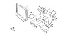
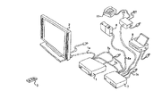
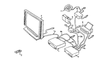
図1及び図2は実施の形態1のシステム外観斜視図及びシステム構成図である。
【0029】
実施の形態1におけるテレビ受像機は、チューナーなどからなるテレビ受像機本体1とプラズマディスプレイなどからなるテレビ表示部2は別体で、ケーブル1aを介して接続されており、テレビ受像機本体1からテレビ表示部2に画像及び音声信号が送られる。テレビ受像機本体1の操作はテレビリモコン3によって行なわれる。テレビ受像機本体1とテレビ表示部2には、それぞれケーブル1b、2aを介して商用電源が供給される。
【0030】
画像蓄積装置4はテレビ受像機本体1に二本のケーブルで接続されており、ケーブル4aを介してテレビ受像機本体1から画像蓄積装置4に制御信号が送られると共に、ケーブル4bを介して画像蓄積装置4からテレビ受像機本体1のAV入力に画像信号および音声信号が送られる。画像蓄積装置4はハードディスクなどの大容量メモリを持ち、大量のデジタル画像を管理データと共に記憶する。なお、画像蓄積装置4には、ケーブル4cを介して商用電源が供給され、プリンタ9がケーブルで接続されている。
【0031】
テレビリモコン3は、テレビモードではテレビ受像機本体の通常テレビ機能を制御する。テレビリモコン3において後述のアルバムモードボタンが操作されると、アルバムモードとなり、テレビリモコン3の操作に応答してテレビ受像機本体1は画像蓄積装置4を制御し、テレビリモコン3の操作に応じた画像信号がテレビ受像機本体1に送られてテレビ表示部2に表示される。
【0032】
ステーション5はデジタルスチルカメラ(以下デジタルカメラ)6のための収納部を持ち、収納部には給電端子5fと信号端子5dが設けられていて、これらの端子はデジタルカメラ6をステーションの収納部に収納することにより、対応するデジタルカメラの端子と接続される。ステーション5は、ケーブル5aを介して商用電源から電力が供給されるACアダプタ5eを持ち、その出力が給電端子5fにつながっている。ステーション5のIEEE1394コネクタ5cはケーブル5bを介してそのまま画像蓄積装置4に直結している。このようにステーション5は、デジタルカメラ収納部、信号端子5d、IEEE1394コネクタ5cおよび給電端子5fとACアダプタ5eを持つ簡単な構成であり、デジタルカメラ6に合った専用のものが用意されている。これに対して、画像蓄積装置4は汎用であり、ケーブル5b接続用のコネクタ形状を規格化することにより、個々のデジタルカメラに合ったステーションにつなぎ換えて使用できる。
【0033】
デジタルカメラ6がステーション5に収納されると、まずデータ転送が自動的に起動され、ケーブル5bを介して画像蓄積装置4にデジタルカメラ内の全てのデジタル画像信号が自動転送される。自動転送がエラーなしに完了したことが確認されると、デジタルカメラ内のメモリ内容は全て自動消去される。このときメモリのエンプティを示すLED5kが点灯する。データ転送が完了すると充電が自動的に起動され、完了と共に自動停止する。このとき充電完了を示すLED5mが点灯する。従って、デジタルカメラ6をステーション5に収納したまま放置すれば、データ転送及び充電が完了し、デジタルカメラ6をステーション5から取り外したとき即座に使用可能となる。デジタルカメラ6の取り外しの際にはLED5kとLED5mを確認する。なお、デジタルカメラの放置により自然放電があった時は、自動的に充電動作が繰り返される。
【0034】
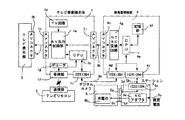
図2は本発明の実施の形態1のシステム構成図あり、ケーブル1aはテレビ受像機本体1のAVコネクタ1cおよびテレビ表示部2のAVコネクタ2b間を接続する。通常のテレビモードにおいて、テレビ受像機本体1はチューナーを含むTV回路1dからの信号をAV出力制御部1eを介してAVコネクタ1cに送っている。受信部1fはテレビリモコン3の送信部3aからの赤外信号を受け、受信内容はデコーダ1gを介してCPU1hに伝達される。テレビモードにおいてはテレビリモコン3の操作に応じてTV回路1dが制御され、チャンネルや音量の変更などが行われる。
【0035】
テレビリモコン3によりモード変更の操作が行われ、デコーダ1gからの信号に基づいてCPU1hがテレビモードからアルバムモードへの変更を検出すると、AV出力制御部1eはTV回路1dからの信号に換えて、AVコネクタ1iからの信号をAVコネクタ1cに送るようになる。さらに、アルバムモードになると、デコーダ1gからの信号に基づいてCPU1はIEEE1394コネクタ1jからIEEE1394規格によるケーブル4aを介して画像蓄積装置4のIEEE1394コネクタ4dに制御信号を送る。このようにして、テレビリモコン3の操作による画像蓄積装置4の制御が可能となる。例えば、テレビリモコン3によって画像の送りを指示すると、受信部1f、デコーダ1g、CPU1h、IEEE1394コネクタ1j、ケーブル4a、IEEE1394コネクタ4dのルートで画像送りの制御信号が画像蓄積装置4に送られる。これによって、IEEE1394コネクタ4dに接続されているCPU4eは画像送り信号であることを検知し、ハードディスクなどからなる記憶部4fから次の画像を読み出して、NTSC(National Television System Committee)変換回路4gを介しAVコネクタ4hからケーブル4bを通してAVコネクタ1iに読み出した次画像の信号を送る。
【0036】
IEEE1394規格によるケーブル5bは、画像蓄積装置4のIEEE1394コネクタ4iとステーション5のIEEE1394コネクタ5cとの間に接続されている。IEEE1394コネクタ5cから信号端子5dの間はステーション5内で直結になっている。信号端子5dはIEEE1394規格によるが端子形状はデジタルカメラ6専用の形状となっている。商用電源5aに接続されているACアダプタ5eの出力は充電端子5fに接続されている。信号端子5dと充電端子5fは1つの接続コネクタ内にまとめられている。デジタルカメラ6の信号端子6aと充電端子6cもこれに対応して1つの接続コネクタ内にまとめられている。デジタルカメラ6をステーションに収納すると、デジタルカメラ6の信号端子6aがステーションの信号端子5dと接触すると共に、デジタルカメラ6充電池6bに接続されている充電端子6cがステーション5の充電端子5fと接触する。これによって、デジタルカメラ6の画像信号が信号端子6a、信号端子5d、IEEE1394コネクタ5c、ケーブル5b、IEEE1394コネクタ4iを通じて画像蓄積装置4のCPU4eに吸い上げられると共に、充電池6bに対してACアダプタ5eから充電が行われる。
実施の形態1のテレビ受像機は、テレビ受像機本体1とテレビ表示部2とを別体に構成したものを説明した。しかし、テレビ受像機として、テレビ受像機本体とテレビ表示部とを一体に構成してもよい。
【0037】
なお、上記の例では、画像蓄積装置4からテレビ受像機本体1へ、画像蓄積装置4内のNTSC変換回路4gで変換されたテレビ信号をAVコネクタを介して送信した。
しかし、テレビ受像機本体1に設けられたIEEE1394コネクタ1jを介してテレビ信号に変換していないデジタル信号を受信し、テレビ受像機本体1のTV回路1dによりテレビ信号に変換してもよい。
【0038】
また、テレビ表示部2のAVコネクタに、画像蓄積装置4からの信号をテレビ受像機本体1を介さずに直接送信することも可能である。
更に、テレビ表示部2には、不図示であるがIEEE1394インターフェース、IEEE1394コネクタを備えている。デジタル信号をIEEE1394コネクタを介して送信してもよい。
(2)各構成及び機能
次に本発明のシステムを構成する画像蓄積装置、ステーション及びデジタルカメラの各構成及び機能について説明をする。
【0039】
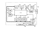
図3は、実施の形態1の画像蓄積装置4の構成を示すブロック図である。
本実施の形態1の画像蓄積装置4は、以下に説明する装置により構成される。
CPU4eは、画像蓄積装置4内の装置を制御し、デジタルカメラ6内のCPU6hと連携して、後述する図6、図7、図8のフローを処理する。また、CPU4eにはROMが搭載されており、画像等のデータが記憶されている。
【0040】
カードスロット4sは、デジタルカメラ6に装着されるカードメモリ(コンパクトフラッシュ、スマートメディア、メモリースティック等)から画像または音声信号を読み取る装置である。 なお、コンパクトフラッシュは米国San Disk社、スマートメディアは(株)東芝、メモリスティックはソニー(株)のそれぞれ商品名である。
【0041】
カードドライバ4pは、CPU4eからの指令によりカードスロット4sを駆動する装置である。
記憶部4fは、画像または音声信号を大量に保存する不揮発性の大容量ハードディスクである。また、CPU4eで処理されるプログラムも記憶している。
記憶部ドライバ4nは、CPU4eからの指令により記憶部4fを駆動する装置である。
【0042】
MPEG(Moving Picture Expert Group)デコーダ4kは、MPEG方式で圧縮記録された動画像データを伸長し再生するための装置である。
JPEG(Joint Photograpfic Expert Group)デコーダ4tは、JPEG方式で圧縮記録された静止画像データを伸長し再生するための装置である。
フレームメモリ4mは、画像又は音声信号を一時的に記憶しておく揮発性の半導体メモリである。フレームメモリ4mは、デジタルカメラ6からの画像又は音声信号のファイル転送時に使用される他に、テレビ受像機本体1、プリンタ9への画像出力時にも使用される。
【0043】
スイッチ回路4qは、画像蓄積装置4に設けられたスイッチが操作されたことを検出しCPU4eに伝達する回路である。
電源回路4rは、不図示の商用電源と接続され、画像蓄積装置4内の各装置に電力を供給する装置である。
IEEE1394インターフェース4jは、制御信号、画像または音声信号等をテレビ受像機本体1、デジタルカメラ6(ステーション5)、プリンタ9に搭載されたIEEE1394インターフェースと送受信するための装置である。また、テレビリモコン3からの信号を受信し、CPU4eに伝達する。
【0044】
IEEE1394コネクタ4i,4dは、テレビ受像機本体1、デジタルカメラ6(ステーション5)、プリンタ9に搭載されたIEEE1394インターフェース間を結ぶケーブルを接続するためのコネクタである。
NTSC変換回路4gは、デジタル的画像信号をNTSC方式のテレビ信号に変換する装置である。これにより、上記IEEE1394インターフェースを搭載しないテレビであっても画像を再生することができる。
【0045】
AVコネクタ4hは、NTSC変換器4gで変換されたテレビ信号を外部に出力するためのコネクタである。
図4は、実施の形態1のステーション5の構成を示すブロック図である。
実施の形態1のステーション5について図4を用いて説明する。
ACアダプタ5eは、不図示の商用電源と接続され、装着されるデジタルカメラ6に電力を供給するための電源装置である。また、デジタルカメラ6に装着された充電池6bの充電にも用いられる。
【0046】
DSC接続コネクタ5jは、デジタルカメラ6に設けられたDSC接続コネクタ6nと接続するコネクタであり、図2の信号端子5dと充電端子5fに対応している。DSC接続コネクタ5jは、ACアダプタ5e、IEEE1394インターフェース5cと電気的に接続されている。このDSC接続コネクタ5jを介して、デジタルカメラ6に電力を供給したり、信号の授受をする。信号端子5dは、IEEE1394規格に準拠した信号の授受を行うための端子である。このDSC接続コネクタ5jは、デジタルカメラ6と接続するために設けられた専用形状で構成されたコネクタである。なお、図2では言及しなかったがDSC接続コネクタ5jは、AVコネクタ5gとも電気的に接続する端子も備えている。
【0047】
AVコネクタ5gは、デジタルカメラ6内でNTSC変換されたテレビ信号を外部に出力するためのコネクタである。実施の形態では説明していないが、このAVコネクタ5gと他の機器のAVコネクタとを接続することで、IEEEインターフェースを備えていない機器でもデジタルカメラ6内で変換されたテレビ信号を鑑賞することができる。
【0048】
IEEE1394コネクタ5cは、画像蓄積装置4に搭載されたIEEE1394インターフェース間を結ぶケーブル5bを接続するためのコネクタである。実施の形態では、IEEE1394コネクタ5cを画像蓄積装置4のIEEE1394コネクタ4iと接続した場合についてのみ説明しているが、テレビ受像機本体1、プリンタ9がデジタルカメラ6内の画像、音声ファイルを取り扱える場合には、画像蓄積装置4を介さずにテレビ受像機本体1、プリンタ9に搭載されたIEEE1394インターフェースと接続して、画像、音声ファイルを再生、印刷することができる。
【0049】
LED5iは、メモリ用LED5kと充電用LED5mとを有する。LED5iは、その点灯状態により、デジタルカメラ6内に装着されたカードメモリと充電池5bの状態を使用者に知らしめる。
LEDドライバ5hは、デジタルカメラ6のCPU6hまたは画像蓄積装置4のCPU4eからの指令によりLED5iの点灯制御を行う。
【0050】
図5は、デジタルカメラ6の構成を示すブロック図である。
実施の形態1のデジタルカメラ6について図5を用いて説明する。また、ここでは撮影、画像処理の説明を省略しているが当然、撮影レンズ、撮像素子、画像処理回路等は備えている。
CPU6hは、デジタルカメラ6内の各装置を制御し、画像蓄積装置4内のCPU4eと連携して後述の図26に示すフローを処理する。
【0051】
スイッチ回路6fは、デジタルカメラ6に設けられたレリーズボタン6r、コマンドダイヤル6s等が操作されることを検出してCPU6hに伝達する回路である。
IEEE1394インターフェース6eは、制御信号、画像または音声信号等をテレビ受像機本体1、画像蓄積装置4、プリンタ9に搭載されたIEEE1394インターフェースと送受信するための装置である。
【0052】
IEEE1394コネクタ6dは、IEEE1394インタフェースを備えた他の機器と信号の授受を行うためのコネクタである。実施の形態では説明していないが、ステーション5を介さずに画像蓄積装置4と信号の授受を行うときに使用される。また、テレビ受像機本体1、プリンタ9がデジタルカメラ6内の画像、音声ファイルを取り扱える場合には、画像蓄積装置4を介さずにテレビ受像機本体1、プリンタ9に搭載されたIEEE1394インターフェースと接続して、画像、音声ファイルを再生、印刷することができる。
【0053】
AVコネクタ6mは、NTSC変換されたテレビ信号を外部に出力するためのコネクタである。実施の形態1では説明していないが、このAVコネクタ6mと他の機器のAVコネクタとを接続することで、IEEEインターフェースを備えていない機器でもデジタルカメラ6内で変換されたテレビ信号を鑑賞することができる。
【0054】
DSC接続コネクタ6nは、ステーション5に設けられたDSC接続コネクタ5jと接続するコネクタである。DSC接続コネクタ6nを介して、電力の供給を受けたり、信号の授受をする。DSC接続コネクタ6nは、DSC接続コネクタ5jと同様に、信号端子、充電端子、AV端子を備える。信号端子での信号の授受は、IEEE1394規格に準拠した信号で行われる。このDSC接続コネクタ6nは、ステーション5と接続するために設けられた専用形状で構成されたコネクタである。
【0055】
充電池6bは、デジタルカメラ6内の各装置を駆動するため電力を供給する電池である。充電池6bは、ステーション5内のACアダプタ5eから供給された電力により充電を行う。
カードスロット6iは、装着されたカードメモリ(コンパクトフラッシュ、スマートメディア、メモリースティック等)に画像または音声信号を記録し、また読み取る装置である。
【0056】
カードドライバ6jは、CPU6hからの指令によりカードスロット6iを駆動する装置である。
また、画像蓄積装置4、デジタルカメラ6は電源がOFFの状態でも、IEEE1394インターフェースを介して外部から入力された信号により電源をONすることが可能である。
(a)充電;画像吸い上げフロー
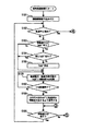
図6、図7に画像蓄積装置4内のCPU4eで実行されるフローチャートを示す。
【0057】
図6に示すフローは、画像蓄積装置4によりステーション5にデジタルカメラ6が接続されたことを検出することによりスタートする。
画像蓄積装置4には常に待機状態でいるため微少電流が流れており、IEEE1394コネクタ4i、ケーブル5b、IEEE1394コネクタ5cを介してステーション5と通信可能状態にある。ステーション5にデジタルカメラ6が接続されたことが検出できる。
【0058】
ステップS151では、デジタルカメラ6からの画像及び音声信号の受信に必要な機能を起動する。具体的には、メイン電源をONし、画像及び音声信号を記録する記憶部4fの駆動、受信プログラムの起動等を行う。
ステップS152では、ケーブル5aを介してステーション5内のACアダプタ5eを駆動させ、デジタルカメラ6に電力を供給するとともに、デジタルカメラ6のメイン電源をONする。当然、接続前からデジタルカメラ6のメイン電源がONしていた場合には、メイン電源のON状態を継続させる。
【0059】
ステップS153では、デジタルカメラ6内に、画像蓄積装置4で取り扱える(再生できる)画像及び音声信号のファイルが存在するか否かを検出する。存在する場合にはステップS154進み、存在しない場合には図7のステップS161に進む。ここで、画像蓄積装置4は、JPEGファイル、MPEGファイル、GIFファイル、ビットマップファイル、フラッシュピックスファイル等の標準化された画像ファイル、WAVEファイル等の音声ファイルは予め取り扱うことができるように設定されている。デジタルカメラには、各メーカーが独自に開発した形式で記録した画像ファイルが存在する場合がある。こうした独自形式の画像ファイルは専用のソフトウェアが無いと取り扱うことができない。また、デジタルカメラに装着されるカードメモリは、デジタルカメラ以外の機器でも使用できるため、文書ファイル等、画像、音声ファイル以外のファイルが存在する可能性もある。画像蓄積装置4で取り扱えないファイルは、受信しても再生することができないので受信しない。
【0060】
しかし、画像蓄積装置4の扱えないファイルは、専用のソフトウェアを画像蓄積装置4にセットアップ(インストール)することにより取り扱えるようになる。セットアップしたことにより取り扱い可能となったファイルは、セットアップ後から自動的に受信することになる。
なお、デジタルカメラ6がカードメモリの着脱可能な場合にカードメモリを備えていない場合には当然ファイルが存在しないと判断される。カードメモリを備えていない場合は、デジタルカメラ6のLCD6qに、カードメモリが存在しないことを使用者に伝える警告表示を行わせるようにデジタルカメラ6を制御する。また、取り扱えないファイルが存在する場合には、デジタルカメラ6のLCD6qに、取り扱えないファイルが存在することを使用者に伝える警告表示を行わせるようにデジタルカメラ6を制御する。
【0061】
ステップS154では、記憶部4fの共通フォルダに日付等の名前を付したフォルダを作成する。例えは、フォルダ名は、「990401-990402」と受信する画像及び音声信号ファイルの最初に記録されたファイルの日時と最後に記録されたファイルの日時を表すようにする。日付情報は画像及び音声信号ファイルのヘッダ部に記録されている日付情報を使用する。共通フォルダは、記憶部4f内に予め作成されているフォルダで、デジタルカメラ6からファイルが転送されるフォルダである。また、画像蓄積装置4には共用フォルダの中に、「家族」「お父さん」「お母さん」「太郎」と名付けられたフォルダが予め作成されている。
【0062】
ステップS155では、ステーション5のメモリ用LED5kを点滅させ、ファイルの転送中であることを使用者に知らしめる。
ステップS156では、デジタルカメラ6から撮影、録音順に画像及び音声信号ファイルを受信し、記憶部4fの「990401-990402」フォルダに記録する。本ステップの信号受信制御については図8を用いて詳述する。
【0063】
ステップS157では、デジタルカメラ6のLCD6qに図11に示すような表示を行い、どのフォルダに保存するか問い合わせる。ここでは、共用フォルダの中に作られているフォルダを選択可能に表示している。フォルダを選択する方法は、コマンドダイヤル6sを回転することでフォルダを選択し、レリーズボタン6rを押すことで選択されたフォルダが指示される。
【0064】
ステップS158では、フォルダが指示されたか否かを検出し、検出された場合にはステップS160に進み、検出されない場合にはステップS159に進む。
ステップS159では、フォルダの問い合わせを始めてから所定時間が経過したかを検出する。所定時間経過していればステップS161に進み、所定時間経過していなければステップS157に戻り、フォルダの問い合わせを継続する。
【0065】
ステップS160では、共用フォルダの中のフォルダ「990401-990402」ごとフォルダ構造を崩すことなく指定されたフォルダに移動する。
ステップS161では、デジタルカメラ6に装着されたカードメモリが空であるか否かを検出する。空である場合はステップS162に進み、空でない場合にはステップS163に進む。
【0066】
ステップS162では、ステーション5のメモリ用LED5kを点灯させ、デジタルカメラ6に装着されたカードメモリが空であることを使用者に知らしめる。
ステップS163では、ステーション5のメモリ用LED5kを消灯させ、デジタルカメラ6に装着されたカードメモリが空でないことを使用者に知らしめる。
【0067】
ステップS164では、デジタルカメラ6のメイン電源をOFFさせる。接続前からデジタルカメラ6のメイン電源がONしていた場合でも、本ステップでデジタルカメラ6のメイン電源をOFFさせる。
ステップS165では、デジタルカメラ6内に充電池6bが装着されているか否かを検出する。充電池6bが装着されている場合にはステップS166に進み、充電池6bでない、または装着されていない場合にはステップS170に進む。
【0068】
ステップS166では、デジタルカメラ6の充電池6bの充電を開始する。
ステップS167では、ステーション5の充電用LED5mを点滅させ、充電池6bが充電中であることを使用者に知らしめる。
ステップS168では、充電が完了したか否かを検出する。完了していればステップS169に進み、完了していなければステップS166に戻り、充電を継続する。
【0069】
ステップS169では、ステーション5の充電用LED5mを点灯させ、充電池6bが充電完了したことを使用者に知らしめる。
ステップS170では、ステーション5に対して電力供給を終了する。
ステップS171では、画像蓄積装置4のメイン電源をOFFし、本フローを終了する。
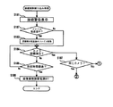
(b)信号受信
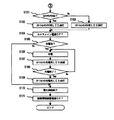
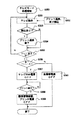
図8〜図10を用いて図6におけるステップS156の信号受信制御について説明する。
【0070】
ステップS101では、デジタルカメラ6とステーション5との接続状態が解除された場合に処理される接続解除割り込み処理の割り込みを可能にする。接続解除割り込み処理は図9を用いて説明する。
ステップS102では、デジタルカメラ6により転送中止が指示されたか否かを検出する。デジタルカメラ6のレリーズボタンが操作されることにより転送中止が指示される。転送中止が指示された場合には図9のステップS110に進み、指示されていなければステップS103に進む。
【0071】
ステップS103では、デジタルカメラ6の未転送ファイルが記録されているフォルダ(階層)構造を検出する。未転送ファイルがフォルダ構造を有している場合はステップS104に進み、フォルダ構造を有していない場合はステップS106に進む。
ステップS104では、ステップS103で検出されたフォルダが画像蓄積装置4内に既に存在しているか検出する。存在していればステップS106に進み、存在していなければステップS105に進む。
【0072】
ステップS105では、図6のステップS154で作成されたフォルダ「990401-990402」内に、更にフォルダを作成する。
ステップS106では、デジタルカメラ6に未転送ファイルを転送するよう指示し、を図6のステップS154、ステップS105で作成されたフォルダ内に記録する。
【0073】
これによりデジタルカメラ6内にフォルダ構造で記録されていた場合には、記録されていたフォルダ構造を崩すことなく画像蓄積装置4に記録でき、整理しやすい。
更にステップS106では、デジタルカメラ6のLCD6qを使用して転送中であることを表示するようデジタルカメラ6に指示する。
【0074】
ステップS107では、デジタルカメラ6から画像蓄積装置4にファイルの記録が完了したか否かを検出する。完了していればステップS108に進み、完了していなければステップS106で転送を継続する。
ステップS108では、デジタルカメラ6内のファイルのヘッダ部に転送済みであることを示す情報を付加するようデジタルカメラ6に指示する。図10のステップS121、ステップS122で、この付加された情報に基づいてファイルが消去される。そしてステップS109に進む。
【0075】
ステップS109では、デジタルカメラ6内に、更に画像蓄積装置4で取り扱うことができる未転送ファイルが存在するか否かを検出する。未転送ファイルが存在する場合にはステップS102に戻り、未転送ファイルが存在しない場合にはステップS116に進む。
前述したステップS102で転送中止の指示を検出した場合、ステップS110で、デジタルカメラ6のLCD6qに図11に示すように転送済みのファイルも含めて全ての転送を中止するか使用者に質問する。
【0076】
ステップS111では、ステップS110の質問に対して「No」が指示されたか否かを検出する。「No」が指示された場合にはステップS116に進む。また、「No」が指示されていない場合はステップS112に進む。ここで、使用者により「No」が指示された場合には転送済みのファイルは転送したままでよいと判断される。
【0077】
ステップS112では、ステップS110の質問に対して「Yes」が指示されたか否かを検出する。「Yes」が指示された場合にはステップS114に進み、「Yes」が指示されていない場合はステップS113に進む。ここで、使用者により「Yes」が指示された場合には、充電をするためにステーション5に装着したものと判断される。「Yes」か「No」を指示する方法は、コマンドダイヤル6sを回転することにより「Yes」または「No」を選択し、レリーズボタン6rを押すことにより選択されたほうが指示される。
【0078】
ステップS114では、今回転送したファイルとフォルダ、更に「990401-990402」フォルダを画像蓄積装置4内の記憶部4fから削除する。
ステップS115では、デジタルカメラ6内のファイルのヘッダ部に付加された転送済み情報を解除するようデジタルカメラ6に指示する。
ステップS113では、転送中止指示がなされてから所定時間が経過したか否かを検出する。所定時間経過していなければステップS110に戻り、指示を待つ。所定時間経過した場合には、ステップS102の転送中止指示により充電のみをするためにステーション5に装着されたものと見なしステップS114に進む。
【0079】
ステップS116では、プロテクトされたファイルを転送したか否かを検出する。プロテクトされたファイルを転送している場合はステップS117に進み、プロテクトされたファイルを転送していない場合はステップS122に進む。プロテクトとは、カードメモリに記録されたファイルを誤消去してしまわないようにファイル管理するようデジタルカメラ6に備えられた機能である。通常、プロテクトを解除しない限りそのファイルは消去することはできない。
【0080】
ステップS117では、図11に示すようにプロテクトされたファイルを消去するかLCD6qに表示する。
ステップS118では、ステップS517の質問に対して「No」が指示されたか否かを検出する。「No」が指示されたことを検出した場合はステップS122に進む。また、「No」が指示されたことを検出しない場合はステップS119に進む。
【0081】
ステップS119では、ステップS117の質問に対して「Yes」が指示されたか否かを検出する。「Yes」が指示されたことを検出した場合はステップS121に進む。また、「Yes」が指示されたことを検出しない場合はステップS120に進む。
ステップS120では、プロテクトされたファイルを消去するかLCD6qに表示し始めてから所定時間が経過したか否かを検出する。所定時間経過していなければステップS117に戻り、指示を待つ。また、所定時間経過していればステップS121に進む。ここでは特に指示されない場合には、カードメモリの空き容量を増やすために、プロテクトされたファイルを削除するようにした。
【0082】
ステップS121では、ステップS108でファイルのヘッダ部に付加された転送済み情報を検索して、デジタルカメラ6から転送が完了しているファイルを削除する。
ステップS122では、ステップS108でファイルのヘッダ部に付加された転送済み情報とプロテクト情報を検索して、デジタルカメラ6から転送が完了しているファイルのうちプロテクトされていないファイルのみを削除する。
【0083】
ステップS123では、接続解除割り込み処理の割り込みを不可にし、本フローを終了する。
(c)途中取り外し
図9を使用して接続解除割り込み処理を説明する。本フローは、割り込みが可能である状態において、ステーション5とデジタルカメラ6との接続が解除されることによりスタートする。
【0084】
ステップS181では、デジタルカメラ6の表示部を使用して接続されていないことを警告し、使用者に接続することを促す。
ステップS182では、ファイルの転送途中に接続解除があり、記憶部4f内に転送が完了していないファイルが存在するか否かを検出する。存在する場合にはステップS183に進み、存在しない場合にはステップS184に進む。
【0085】
ステップS183では、記憶部4f内の転送完了していないファイルを削除する。
ステップS184では、デジタルカメラ6とステーション5が接続されたか否かを検出する。接続されたことが検出された場合にはステップS187に進み、検出されない場合にはステップS185に進み。
【0086】
ステップS187では、再度接続されたデジタルカメラが前回接続されていたデジタルカメラ6であるか判別する。同じデジタルカメラ6であった場合には図8のステップS109に進む。これにより、既に作成されたフォルダに転送を可能にする。異なるデジタルカメラであった場合には図6のステップS152に進む。
【0087】
ステップS185では、接続が解除されてからの経過時間が所定時間を越えたか否かを検出する。経過時間が所定時間を越えた場合にはステップS186に進み、越えていない場合にはステップS184に戻る。
ステップS186では、画像蓄積装置4の電源をOFFして本フローを終了する。
【0088】
実施形態1では、全てのファイルの転送が終了した後に、正常に転送したファイルに対応するデジタルカメラ6内のファイルを一括して消去するよう構成した。しかし、それだけに限らず、1つのファイルの転送が終了した時点で対応するファイルを個別に消去するようにしてもよい。なお、実施形態1のデジタルカメラでは、転送が終了したファイルを実際に消去する例を説明したが、ファイルの上書き可能なデジタルカメラではファイルのヘッダ部に消去可能情報を付加するのみで実際に消去しなくてよい。
【0089】
また、本実施の形態1では、画像蓄積装置4によりデジタルカメラ6の装着を検出したが、テレビ受像機本体1により検出するようにしてもよい。
また、本実施の形態のフローチャートの制御は、画像蓄積装置4内のCPU4eにより実行させたがテレビ受像機本体1内のCPU1hにて実行してもよい。(d)デジタルカメラ6内CPU6hでの処理
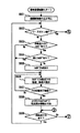
また、図8に示したフローチャートはデジタルカメラ6内のCPU6hにより実行させてもよい。以下にデジタルカメラ6内のCPU6hにより実行する実施の形態を図13を用いて説明する。
【0090】
ステップS501では、デジタルカメラ6とステーション5との接続状態が解除された場合に処理される接続解除割り込み処理の割り込みを可能にする。接続解除割り込み処理は図12を用いて説明する。
ステップS502では、デジタルカメラ6のレリーズボタンが操作され転送中止が指示されたか否かを検出する。転送中止が指示された場合にはステップS510に進み、指示されていなければステップS503に進む。
【0091】
ステップS503では、未転送ファイルが記録されているフォルダ(階層)構造を検出する。未転送ファイルがフォルダ構造を有している場合はステップS504に進み、フォルダ構造を有していない場合はステップS506に進む。
ステップS504では、ステップS503で検出されたフォルダが画像蓄積装置4内に既に存在しているか検出する。存在していればステップS506に進み、存在していなければステップS505に進む。
【0092】
ステップS505では、画像蓄積装置4の記憶部4fに図6のステップS154で作成されたフォルダ「990401-990402」内に、更にフォルダを作成するように画像蓄積装置4に指令する。
ステップS506では、未転送ファイルを画像蓄積装置4に転送し図6のステップS154、ステップS505で作成されたフォルダ内に記録するよう指示する。
【0093】
これによりデジタルカメラ6内にフォルダ構造で記録されていた場合には、記録されていたフォルダ構造を崩すことなく画像蓄積装置4に記録されるため整理しやすい。
更にステップS506では、LCD6qに転送中であることを表示する。
ステップS507では、画像蓄積装置4に転送したファイルの記録が完了したか否かを検出する。完了していればステップS508に進み、完了していなければステップS506で転送を継続する。画像蓄積装置4は、転送されたファイルが記憶部4fへの記録が完了したときに完了信号を送信するようになっている。
【0094】
ステップS508では、デジタルカメラ6内のファイルのヘッダ部に転送済みであることを示す情報を付加する。図15に示すステップS521、ステップS522で、この付加された情報に基づいてファイルが消去される。そしてステップS509に進む。
ステップS509では、デジタルカメラ6内に、更に画像蓄積装置4で取り扱うことができる未転送ファイルが存在するか否かを検出する。未転送ファイルが存在する場合にはステップS502に戻り、未転送ファイルが存在しない場合にはステップS516に進む。
【0095】
ステップS510では、デジタルカメラ6のLCD6qに図11に示すように転送済みのファイルも含めて全ての転送を中止するか使用者に質問する。
ステップS511では、ステップS510の質問に対して「No」が指示されたか否かを検出する。「No」が指示されたことを検出した場合にはステップS516に進む。また、「No」が指示されたことを検出しない場合はステップS512に進む。ここで、使用者により「No」を指示された場合には転送済みのファイルは転送したままでよいと判断される。
【0096】
ステップS512では、ステップS510の質問に対して「Yes」が指示されたか否かを検出する。「Yes」が指示されたことを検出した場合にはステップS514に進み、「Yes」が指示されたことを検出しない場合はステップS513に進む。ここで、使用者により「Yes」を指示された場合には、充電をするためにステーション5に装着したものと判断される。
【0097】
ステップS514では、今回転送したファイルとフォルダ、更に「990401-990402」フォルダを画像蓄積装置4内の記憶部4fから削除するよう画像蓄積装置4に指示する。
ステップS515では、デジタルカメラ6内のファイルのヘッダ部に付加された転送済み情報を解除する。
【0098】
ステップS513では、転送中止指示がなされてから所定時間が経過したか否かを検出する。所定時間経過していなければステップS510に戻り、指示を待つ。所定時間経過した場合には、ステップS502の転送中止指示により充電のみをするためにステーション5に装着されたものと見なしステップS514に進む。
【0099】
ステップS516では、プロテクトされたファイルを転送したか否かを検出する。プロテクトされたファイルを転送している場合はステップS517に進み、プロテクトされたファイルを転送していない場合はステップS522に進む。プロテクトとは、カードメモリに記録されたファイルを誤消去してしまわないようにファイル管理するようデジタルカメラ6に備えられた機能である。通常、プロテクトを解除しない限りそのファイルは消去することはできない。
【0100】
ステップS517では、図11に示すようにプロテクトされたファイルを消去するかLCD6qに表示する。
ステップS518では、ステップS517の質問に対して「Yes」が指示されたか否かを検出する。「Yes」が指示されたことを検出した場合はステップS522に進む。また、「Yes」が指示されたことを検出しない場合はステップS519に進む。
【0101】
ステップS519では、ステップS517の質問に対して「No」が指示されたか否かを検出する。「No」が指示されたことを検出した場合はステップS521に進む。また、「No」が指示されたことを検出しない場合はステップS520に進む。
ステップS520では、プロテクトされたファイルを消去するかLCD6qに表示し始めてから所定時間が経過したか否かを検出する。所定時間経過していなければステップS517に戻り、指示を待つ。また、所定時間経過していればステップS521に進む。ここでは特に指示されない場合にはプロテクトされたファイルを削除しないようにした。
【0102】
ステップS521では、ステップS508でファイルのヘッダ部に付加された転送済み情報とプロテクト情報を検索して、デジタルカメラ6から転送が完了しているファイルのうちプロテクトされていないファイルのみを削除する。
ステップS522では、ステップS508で付加された転送済み情報を検索して、デジタルカメラ6から転送が完了している全てのファイルを削除する。
【0103】
ステップS523では、接続解除割り込み処理の割り込みを不可にし、本フローを終了する。
(3)画像蓄積装置の動作
テレビリモコンの操作により行われる画像蓄積装置の動作について具体的に説明する。
【0104】
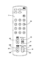
テレビリモコン3の詳細を図16 に示す。テレビ受像機本体1に微小電流が供給されてスタンバイ状態にあるときに、テレビリモコン3の電源ボタン3aが押されると、テレビ受像機本体1のメイン電源がオンとなる。
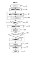
図17は、メイン電源オン後のテレビ受像機本体の基本動作フローである。ステップS1でメイン電源がオンになると、ステップS2においてテレビ受像機本体は常にテレビモードにて立ち上がる。従って、直前の使用において、例えば後述するアルバムモードにてテレビ受像機本体1のメイン電源をオフしていたとしても、新たにメイン電源をオンしたときは、テレビ受像機本体1はテレビモードにて立ち上がる。ここで、テレビモードとは、通常のテレビ放送を受信して鑑賞するモードをいう。ステップS3でアルバムモードなど他のモードへのモード変更操作による割込みを可能にし、ステップS4でメイン電源オフ操作による割込みを可能にしたあと、フローはステップS5のテレビモード動作に入る。
【0105】
ステップS5でテレビモード動作に入り、テレビ放送の表示が始まると、所定時間(例えば5秒間)、テレビ表示部2においてデジタルカメラの情報がテレビ放送画面に重畳して表示される。表示されるデジタルカメラの情報は、例えばデジタルカメラ6のステーション5への載置の有無、デジタルカメラ6から画像蓄積装置4へのデジタル静止画像の転送状況、デジタルスチルカメラの充電状況などである。
【0106】
図16 におけるテレビリモコン3のアルバムボタン3bを押すと、モード変更割込みがかかる。アルバムモードの基本フローを示す図13において、ステップS6でモード変更割込みがかかると、ステップS7でアルバムモードへのモード変更であることが確認し、ステップS8へ進む。なお、モード変更割込みがアルバムモードへものでなかったときは、ステップS7から別モードのフローへ進む。ステップS8ではアルバムモードから他のモードへの変更に必要なモード変更割込み操作を可能とする処理をし、ステップS9ではアルバムモードから直接テレビ受像機本体1のメイン電源をオフ操作するためのメイン電源オフ割込みを可能とする処理をする。
【0107】
ステップS10において、画像蓄積装置4に微小電流が供給されてスタンバイ状態にあることが確認されると、ステップS11で画像蓄積装置4の電源をオンする指示が出され、画像蓄積装置4が立ち上がる。ステップS12では、後述するデータ取込み完了割込みを受け付けるための処理が行われる。一方、ステップS10において画像蓄積装置4がスタンバイ状態でない場合は、ステップS13でテレビ表示部2に「画像蓄積装置の電源を入れてください」とのメッセージが表示され、ステップS14にて画像蓄積装置4の元電源がオンされるのを待つ。画像蓄積装置4の元電源がオンされると、ステップS15でメッセージの表示を終了し、ステップS12に進む。
【0108】
ステップS16では、バックグラウンドミュージックがスタートする。これは、テレビモードで放送を受信している際に通常流れている音声がアルバムモードになって無音状態になる違和感を緩和するためである。このバックグラウンドミュージックはあらかじめ準備されているものがランダムに選ばれる。この機能はユーザ設定によって、バックグラウンドミュージックの代わりにそのままテレビ音声を流す、または完全に無音にするなど、任意に変更できる。
【0109】
ステップS171では、フレームメモリ4mに画像が保持されているか否かを検出する。フレームメモリ4mには、図28のステップS87で画像が保持される。保持されていればステップS172に進み、保持されてなければステップS174に進む。
ステップS172では、図28のステップS87でフレームメモリ4mに保持された表示画像を読み出し、テレビ表示部2に表示する。半導体メモリであるフレームメモリ4mに保持された表示画像は瞬時に読み出され、表示を行うことができる。そのため、アルバムモードに変更されてからテレビ表示部2に画像が表示されるまでの期間を極力短くすることができ、違和感を生じさせない。
【0110】
ステップS173では、記憶部ドライバ4nに指令を出し、記憶部4fの駆動を開始する。そして、ステップS18に進む。
上述したステップS171で画像が保持されてない場合は、ステップS174で、ROM内に予め記憶されたアルバムモードのメニュー画像を読み出し、表示する。ROMは、画像蓄積装置4のCPU4e内に存在している半導体メモリである。ROMに記憶されたメニュー画像も瞬時に読み出され、表示を行うことができる。
【0111】
ステップS175では、記憶部ドライバ4nに指令を出し、記憶部4fの駆動を開始する。
ステップS176では、画像、音声を再生するための再生プログラムを起動する。そして、ステップS17に進む。
ステップS17では、画像蓄積装置4に取込まれた最新のフォルダ中の第1画像が再生され、テレビ受像機本体1に表示される。なお、この機能は、アルバムモードへの変更に応答して、ある一定のルールによって選択された画像を画像蓄積装置4で自動的に再生して表示することを意味するものであり、ある一定のルールによって選択される画像としては、上記の最新のフォルダ中の第1画像に代えて、例えば画像蓄積装置4に取込まれた画像ファイル中の最新撮影日時の画像としてもよい。アルバムモードは、このようにして立ち上がった後、ステップS18のアルバムモード動作に入る。
【0112】
なお、上記の構成に換えて、ステップS174においてテレビモードの表示を継続し、ステップS17で画像の取り込みが行われた後、表示をアルバムモードに切換えるよう構成することもできる。
アルバムモードへモード切換は、画像蓄積装置4がデジタルカメラ6から画像ファイルを取込んでいる最中でも行われる。また、アルバムモードにおいてテレビ受像機本体1を使用中において、画像取込みのためにデジタルカメラ6がステーション5に挿入されることもある。図19はこのような場合に対応する動作を示す。アルバムモードへの切換前にデジタルカメラ6から画像蓄積装置4への画像ファイル取込みが完了していれば、図13のステップS17の機能により取込み完了の最新フォルダの第1画像が表示されるから図19のフローが動作することはない。これに対し、アルバムモードへの切換が行われたあとに画像ファイルのデータ取込みが完了した場合には、図19のステップS19で割込みがかかり、「新しい画像ファイルのフォルダが取込まれた」旨のメッセージをテレビ表示部2の画面表示に重畳して表示する。表示はステップS21で例えば7秒程度の所定時間がカウントされる間続き、ステップS22で終了する。この機能はアルバムモード中はいつでも機能し、メッセージを見た使用者は、後述する操作により任意に新着フォルダの画像を見ることができる。
【0113】
図20は、図18のステップS18のアルバムモード動作の詳細である。すなわち、アルバムモードへの切換に応答して図18のステップS17で画像表示が行われると、図20のステップS24からのアルバムモード動作に移行し、ステップS25〜ステップS30において、以下に詳述する各種の割込みが可能になるとともに、あとは使用者の操作を待ってステップS31で待機状態に入る。図16 のテレビリモコン3のTVアルバムボタン3bが押されてからここまでの動作は、きわめて短時間に行われる。
【0114】
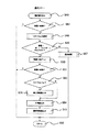
アルバムモードにおいてテレビ表示部2に表示されている画像を送るには、図16 のチャンネルボタン3cの「+」または「−」を操作する。図21はこの場合の動作を示す。画像が表示されている状態においてチャンネルボタン3cが操作されると、図21のステップS32で画面送り割込みがかかる。チャンネルボタン3cの「+」が押されたのであれば、次画面送り操作であるからステップS33からステップS34に移行し、チャンネルボタンが押される前の現画面が、フォルダ中の最終画面かどうかがチェックされる。そして、最終画面でなければステップS35で一画面送りをおこない、ステップS36でリターンする。これに対し、ステップS34で現画面が最終画面であるときは,これ以上送る画面がないから何もせずステップS36でリターンする。つまり、現画面が最終画面であるときはチャンネルボタン3cの「+」を押しても何も受け付けないことになる。ステップS33において次画面送り操作でなかったときは、画面戻しのためにチャンネルボタン3cの「−」が押されたものと判断してステップS37に移行する。ステップS37では、チャンネルボタンが押される前の現画面が、フォルダ中の1枚目の画面かどうかをチェックし、1枚目でなければステップS38で一画面戻しをおこない、ステップS36でリターンする。これに対し、ステップS37で現画面が1枚目であるときは,これ以上戻す画面がないから何もせずステップS36でリターンする。つまり、現画面が1枚目であるときにチャンネルボタン3cの「−」を押しても何も受け付けないことになる。
【0115】
なお、この実施の形態では、「1枚目」および「最終画面」をそれぞれひとつのフォルダ内におけるものとしたが、これに代えて、画像蓄積装置内のすべての画像における「1枚目」および「最終画面」としてもよい。この場合は、最新のフォルダの1枚目まで画像戻しを行ったうえで、さらにチャンネルボタン3cの「−」が押されたときは、ひとつ旧いフォルダの中の最終画面が表示されることになる。以下、最も旧いフォルダの1枚目に到るまで、チャンネルボタン3cの「−」の操作を受け付けて画面戻しが行われる。このようにすれば、後述する階層変更操作を知らない使用者であっても、一応は画像蓄積装置内の全画像を見ることができる。
【0116】
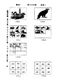
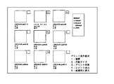
図22はテレビ表示部2に表示される種々の画面を示したもので、(G1)、(G2)は画像が表示されている場合である。図16と対応づければ、画像(G1)が表示されている状態でチャンネルボタン3cの「+」を押すと画像(G2)への次画面送りが行われ、画像(G2)が表示されている状態でチャンネルボタン3cの「−」を押すと画像(G1)への画面戻しが行われる。
【0117】
図22において、(S1)、(S2)は連続する九つの画像をテレビ表示部2の画面を9分割して縮小一覧
表示したものであり、デジタルカメラのサムネイル表示に対応するものである。ここでは、14つの画像が存在する場合を示している。
一方、(F1)は連続する7つのフォルダの情報をテレビ表示部2の画面を9分割して一覧表示したものであり、それぞれにフォルダ名称、日付、内容、等の文字表示とそのフォルダの1枚目の縮小画像が表示されている。ここでは、7つフォルダが存在する場合を示している。
また、(Y1)、(Y2)は連続する九つの年をテレビ表示部2の画面を9分割して一覧表示したものである。ここでは、18つ以上の年が存在する場合を示している。画像蓄積装置4は、これら「サムネイル」、「フォルダ」、「年」を、テレビ表示部2に予め決められた9分割で表示させるため、9つ以下の場合は全ての画像を同時に表示し、9つ以上存在する場合は9つ毎に画像を分けて表示するよう制御する。したがって、9つ以上のフォルダが存在する場合には(S1)、(S2)のサムネイル一覧表示がフォルダ一覧表示に置き換わったような表示形態になる。
【0118】
また、これらの「画像」、「サムネイル」、「フォルダ」、「年」を階層と呼ぶことにする。
アルバムモードにおいてテレビ表示部2に表示されている階層を変更するには、図16 の音量ボタン3dの「+」または「−」を操作する。図23はこの場合の動作を示す。画像が表示されている状態において音量ボタン3dが操作されると、図23のステップS39で階層変更割込みがかかる。音量ボタン3dの「+」が押されたのであれば、階層アップ操作であるからステップS40からステップS41に移行し、音量ボタン3dが押される前の現画面が、階層中の年かどうかがチェックされる。そして、年でなければステップS42で階層を一段アップし、ステップS43でリターンする。例えば、図22において画像(G1)からサムネイル(S1)に移行する。この場合、サムネイル(S1)は9分割された画面の左上隅に画像(G1)を配し、画像(G2)をその右に配して、以下この順で画像(G1)を筆頭とする一連の九つの画像を表示するものとする。なお、表示のルールとしては、画像(G1)を左上隅に配するのに代え、9分割画面の中央に配するようにすることもできる。
【0119】
ステップS40で現階層が年であるときは,これアップする階層がないから何もせずステップS43でリターンする。つまり、現階層が年であるときは、音量ボタン3dの「+」を押しても何も受け付けないことになる。なお、図23において、階層を記憶するレジスタをサイクリックとし、ステップS41を省略すれば、現階層が年であるときにさらに音量ボタン3dの「+」を押したときには画像階層に戻るように構成してもよい。このことは以下に説明するステップS44についても同様である。
【0120】
ステップS40において階層アップでなかったときは、階層ダウンのために音量ボタン3dの「−」が押されたものと判断してステップS44に移行する。ステップS44では、音量ボタン3dの「−」が押される前の現階層が、画像かどうかをチェックし、画像でなければステップS45で階層を一段ダウンし、ステップS43でリターンする。例えば、図22においてフォルダ(F1)からサムネイル(S1)に移行する。この場合、サムネイル(S1)はフォルダ(F1)の9分割された画面の左上隅のフォルダの中の最初の9画面を表示するものとする。
【0121】
ステップS44で現階層が画像であるときは,これ以上階層をダウンできない何もせずステップS43でリターンする。つまり、現階層が画像であるときに音量ボタン3dの「−」を押しても何も受け付けないことになる。これに代えて、操作を受け付けて階層をサイクリックに変更するよう構成できることは上述したとおりである。
【0122】
階層ダウン操作については、上記の階層変更割込みによるほか、図24に示す選択フローによっても行われる。一例として、図22のサムネイル(S1)が表示されている状態において、図16 のテレビリモコン3にある12キー3eの「2」のボタンを押すと、画面は、画像(G2)に切換わる。つまり、テレビリモコン3において12キー3eのボタン「1」〜「9」は二次元配置的にテレビ表示部2の九つの分割画面とそれぞれ対応付けられており、ボタンを押すことによって分割画面の中から対応する位置のものが選択されることになる。上記の例では画像(G2)に対応する画像はサムネイル(S1)の9分割画面のうち上段中央に配されているが、12キー3eの「1」〜「9」の配置において上段中央にあるのはボタン「2」なので、このボタン「2」を押すことで、画像(G2)が選択されたことになる。
【0123】
以上の動作を、図24の選択フローで詳しく見る。今度は、年(Y2)がテレビ表示部2に表示されている場合を例にとって説明する。年表示は年を手がかりに画像検索するときに使用する。例えば、1988年作成のフォルダから画像を探したいとする。この場合、年(Y2)の表示において、「1988」は中段右側にあるので、これを選択するために12キー3eの配置で中段右側にある「6」のボタンを押す。これによって、図24のステップS46において選択割込みがかかる。ステップS47で現在の階層が画像であるかどうかがチェックされ、画像であればなにもせず、ステップS52でリターンする。つまり、テレビ表示部2に表示されているのが画像であれば、選択の対象はないので、12キー3eの各ボタンの操作は一切受け付けない。今回の例では階層は年であるからステップS47からステップS48に進む。ステップS48においては、12キー3eのボタン「6」が押されたことにより、1988年作成の全フォルダの選択処理が行われるとともに作成日順位に整理される。ステップS49では階層が年、フォルダ、サムネイルのいずれかかどうかがチェックされる。今回の例では階層は年であるからステップS50で階層が一段ダウンされてフォルダの階層となる。これによってテレビ表示部2にはフォルダ(F1)が表示される。フォルダ(F1)の9分割画面には1988年作成の最も早い日付のものを筆頭に上段左側から日付順にフォルダの情報が表示される。ステップS51では一段ダウンした結果の新しい階層が画像かどうかのチェックが行われる。今回の例では、新しい階層はフォルダなのでそのままステップS52でリターンとなる。
【0124】
図24のステップS53からステップS56は、以後の検索の情報として各画像に処理履歴を書込むための動作を示す。ステップS51おいて一段ダウンした結果の新しい階層が画像であるときはステップS53において「マイ・アルバム」モードにおける使用であるかどうかチェックされる。「マイ・アルバム」モードの詳細は後述する。「マイ・アルバム」モードでなければ、ステップS54で画像選択日時がその画像データのヘッダ部に書込まれ、ステップS55でその画像に到った検索履歴などその他の選択条件がその画像のヘッダ部に書き込まれる。これらの情報は、後日同じ画像を検索するときの手がかりとして機能する。例えば画像選択日時は、「1週間前に見た画像」という検索条件にて同じ画像を検索する際に有用である。ステップS53において「マイ・アルバム」モードにおける使用であると判断されると、誰が検索した画像かという個人情報がステップS54においてその画像のヘッダ部に書き込まれ、後日の検索の手がかりとして機能する。なお、ステップS49において階層がいずれにも該当しない場合は、階層変更に関係しない選択が行われたと判断され、ステップS57においてそのために必要な選択処理が行われる。この動作の代表的なものはマイ・アルバムモードにおける個人の選択である。
【0125】
ここで、マイ・アルバムモードにおける個人の選択について説明する。図16のテレビリモコン3におけるメニューボタン3fを押すと、テレビ表示部2に9分割画面があらわれ、それぞれ12キー3eの「1」〜「9」の配列どおりに1〜9の数字が表示される。この表示は別途適宜の入力手段によって家族の個人名などに置き換えることも可能である。この動作を図25のマイ・アルバムフローで説明すると、メニューボタン3fの操作により、ステップS56でマイ・アルバム割込みがかかり、ステップS57においてテレビ表示部2に12キー3eの「1」〜「9」の配列どおりに1〜9の数字が表示されことになる。このフローはステップS58でリターンし、12キー3eの操作を待つ。例えば、操作者が家族の父であり、数字1を割り当てていたとすると、12キー3eの「1」を押すと図24のステップS46からステップS49および、ステップS57、ステップS52が機能する。この結果、以後の操作において画像の選択をしたとすると、図24のステップS51、ステップS53、に続いてテップS56において選択した画像のヘッダ部に「父」の情報が書込まれる。
【0126】
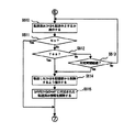
図16 のテレビリモコン3における選択ボタン3gを操作すると、図26におけるステップS59で検索割込みがかかり、ステップS60においてテレビ表示部2に検索条件入力画面が表示される。選択ボタン3gをさらに適宜操作することにより、ステップS61において表示された検索条件における検索カテゴリーを変更することができる。選択した検索カテゴリーにおいて日付などの検索条件を入力するには12キー3eを用いる。これによってステップS62が機能する。検索条件が決まったら、図16 のテレビリモコン3における決定ボタン3hを押すことによりステップS63からステップS64に進む。ステップS61からステップS63は、最終操作結果を保存しながら、所定時間毎に繰り返されるので、決定ボタン3hを押さない限り、ステップS61、ステップS62における修正は繰り返し可能である。ステップS64では検索が実行されると共に結果のフォルダが作成され、ステップS65で検索結果が図22のサムネイル(S1)のような形式で表示される。なお、検索結果のヒット画像数が多い場合や検索条件に階層がある場合は、適宜複数のフォルダに検索結果が分離され、図22のフォルダ(F1)のような形式で表示される。検索結果のヒット画像のヘッダ部にはステップS66からステップS69により、後日の検索のための情報が書込まれステップS70でリターンする。なお、フォルダがある場合には、フォルダにも同様の情報を書込むようにしてもよい。
【0127】
次に画像のプリントについて説明する。テレビ表示部2に画像が表示されている場合において、その画像をプリントしたいときは、テレビリモコン3における決定ボタン3hを押すと、図27のステップS71でプリント割込みがかかる。この場合、テレビ表示部2に表示されている階層が画像でないときに誤って決定ボタン3hが押されても何も受け付けず、ステップS72からステップ78に飛んでリターンする。階層が画像であったときはステップS72からステップS73に進む。ステップS73からステップS75は、後日の検索のために画像のヘッダ部に情報を書込む機能である。ステップS751では、画像のヘッダ部にプリント情報が有るか否かを検出する。プリント情報がない場合にはステップS76に進む。ステップS76では画像のヘッダ部にプリントすべき旨の情報が書込まれる。ステップS77では、テレビ表示部2の画像表示に「プリント受付」の旨を重畳表示する。また、ステップS751でプリント情報が有る場合にはステップS752に進む。ステップS752では画像のヘッダ部に書き込まれたプリント情報を消去する。ステップS753では、テレビ表示2の画像表示に重畳表示された「プリント受付」を消去する。以上の動作によりステップS78にリターンしするので、この動作は別の画像を呼び出して何度でも行うことができる。プリントの実行は、アルバムモード終了の際にまとめて行われる。
【0128】
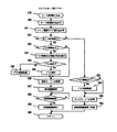
他のモードへの変更操作をする、あるいは画像蓄積装置4の主電源が不用意に落とす操作をするとき、アルバムモードは終了する。例えば、アルバムモードからテレビモードに戻るにはTVアルバムボタン3bを押す。ビデオモード1に変更するにはビデオ1ボタン3jを押す。画像蓄積装置4の主電源スイッチを操作する。これらのいずれかの操作がおこなわれると、アルバムモード終了フローを示す図28のステップS79においてモード変更割込みがかかる。ステップS80、ステップS81ですでに説明した割込み可能処理をした後、ステップS91ではアルバムモード終了フローが開始されたのが他モードへの変更操作によるものか、それとも画像蓄積装置4の主電源を落とす操作によるものかを判別し、他モードへの変更操作によるものである場合はステップS82に進む。ステップS82ではプリント情報のある画像があるかどうかをチェックする。該当する画像があればステップS83において、図22のサムネイル(S1)の形式でそれらを表示する。この状態でテレビリモコン3の決定ボタン3hが押されると、ステップS85でプリントの実行が行われるとともに、各画像のヘッダ部にプリント実行済みの情報が書込まれる。この後、ステップS86において、指定されたモードへの変更が行われ、ステップS87でリターンする。ステップS85からステップS86への移行はプリント指示直後に行われ、実際のプリントの実行は他のモードのバックグラウンド、例えばテレビ放送受信鑑賞中に行われる。
【0129】
ステップS82でプリントすべき情報がなければ直接ステップS86に飛ぶ。また、ステップS84において、決定ボタン3hの代わりに、テレビリモコン3のメニューボタン3fが押されるとステップS90でプリント保留処理が行われ、プリントを実行せずにステップS86に移行する。ステップS90では、各画像のヘッダ部にその旨の情報が書込まれ、以後テレビ受像機本体の電源オン時、モード変更時など、適宜の節目でプリント未実行の画像がある旨のメッセージの表示が所定時間行われる。この表示は、各画像のプリント実行を行うか、プリント指示の取り消し操作をするまで、繰り返し行われる。
【0130】
ステップS87では、表示画面をフレームメモリ4mに保持する。ここで、表示画像をフレームメモリ4mに保持する理由は、再度、アルバムモードに変更されたときに他のモードに変更される前のアルバムモードと同じ状態にするためである。なお、この処理以降は、指定モードの処理のバックグランドで並列して制御される。
【0131】
ステップS88では、他のモードに変更されてから所定時間が経過したか否かを検出し、所定時間経過していればステップS89に進み、経過していなければ計時を継続する。
ステップS89では、省電のため画像蓄積装置4の記憶部4fの駆動を停止させ、省電力モードにする。ここで、所定時間経過した後に省電力モードに移行する理由を説明する。例えば誤って他のモードに移ってしまった場合、すぐに画像蓄積装置モードに戻る可能性がある。このような場合にいちいち記憶部4fの駆動停止、駆動開始を繰り返すと、アルバムモードが動作可能になるまでに時間がかかってしまうし、また、記憶部4fの負担が大きくなる。
【0132】
また、上述のステップS91で画像蓄積装置4の主電源を落とす操作によるものである場合は、ステップS92に進む。ステップS92では、プリント情報のある画像があるかどうかをチェックする。該当する画像があればステップS93でプリント保留処理が行われ、プリントを実行せずにステップS94に移行する。ステップS93では、各画像のヘッダ部にその旨の情報が書込まれ、以後テレビ受像機本体の電源オン時、モード変更時など、適宜の節目でプリント未実行の画像がある旨のメッセージの表示が所定時間行われる。この表示は、各画像のプリント実行を行うか、プリント指示の取り消し操作をするまで、繰り返し行われる。ステップS92で該当する画像がなけれはステップS94に飛ぶ。ステップS94ではテレビモードに移行し、ステップS95に進む。ステップS95では画像蓄積装置4に対して、記憶部4fの駆動を停止させる等の終了処理を施して主電源をオフする。
【0133】
プリンタ9は電源ON、OFFも含めた全ての機能を画像蓄積装置7によって制御される。画像蓄積装置7のCPUは、プリンタ9を制御する制御指令をテレビ受像機本体1のテレビリモコン3からテレビ受像機本体1を介して受け、該受けた制御指令をプリンタ9に伝達する。前記CPUは、画像蓄積装置7及び該画像蓄積装置7に接続された各種機器の状態を参照して、指示された制御指令出力の許諾、出力のタイミングを決定し実行する。
【0134】
さらに、次のような利点がある。即ち、他の機器の動作、状態との整合性をもってプリンタ9を作動させることができる。画像蓄積装置7専用のリモコンを必要とせず、テレビリモコン1つで済み、且つテレビリモコンの通信先は制御対象の機器が何であるかに係わらず常にテレビ受像機本体1であるので使い勝手が良い。テレビ受像機本体1以外の機器はリモコンからの信号を受けないので、従来のように各機器を信号受信部がリモコン操作位置から見通せることという設置上の制約がない。
(実施の形態2)
次に本発明の他の実施の形態2について説明する。
【0135】
図29、図30は、本発明の実施の形態2のシステム外観斜視図及び構成ブロック図である。図29において、画像蓄積装置7とデジタルカメラ8以外の構成は図1に示した実施の形態と共通である。なお、実施の形態2では、さらに画像蓄積装置7に電話通信用モデム10および電話機11が接続されているが、これらの接続は実施の形態1でも可能である。
【0136】
本発明の実施の形態2ではデジタルカメラ8に給電するACアダプタが画像蓄積装置7自身に設けられており、ケーブル8aはACアダプタからの給電路とデジタルカメラからの信号伝達路が一本にまとめられた専用規格のものになっている。この実施の形態でも、画像蓄積装置7は汎用であり、専用規格ケーブル8aのみがデジタルカメラ8用の専用品となる。また、この実施の形態においても、充電のためにデジタルカメラ8とにケーブル8aを接続するだけで、データ転送及び充電が自動起動される。
【0137】
実施の形態2のシステム構成ブロック図である図30において、デジタルカメラ8は、IEEE1394に準拠した信号端子と充電端子が一つにまとめられた専用規格の接続ターミナル8cをもつ。接続ターミナル8cの信号端子はデジタルカメラの回路系に接続されていると共に、充電端子は充電池6bに接続されている。接続ターミナル8cにはケーブル8aが接続されるが、このケーブル8aは充電路8dとIEEE1394に準拠した信号伝達路8eが一本のケーブルとしてまとめられた専用規格のものである。これと対応して画像蓄積装置7は、IEEE1394に準拠した信号端子と充電端子が一つにまとめられた専用規格の接続ターミナル7iをもつ。接続ターミナル7iの充電端子はACアダプタ7jに接続されると共に、信号端子はIEEE1394端子7kに接続されている。
【0138】
上記のように、画像蓄積装置7は種々のデジタルカメラに使用可能な汎用品であるが、デジタルカメラによっては電源電圧が異なる。そこで、ACアダプタ7jは複数の電圧を選択して出力できるよう構成されており、画像蓄積装置7のCPU7eは、デジタルカメラ8の接続ターミナル8c、信号伝達路8e、接続ターミナル7i、IEEE1394端子7kを介して、デジタルカメラ8の電源電圧の情報を検知し、検知結果に応じてACアダプタ7jを制御してデジタルカメラ8に適した電圧を選択して出力させる。このようにして、デジタルカメラ8は、接続ターミナル8cさえ専用規格としておけば、異なった電源電圧を採用することが可能である。
【0139】
図30において、IEEE1394端子7mにはプリンタ9が接続されている。図30では図29のモデム10の接続の図示は省略しているが、その構成は同様である。図30のその他の構成は図2に準じて理解できるので説明を省略する。
本発明の他の実施の形態2のテレビリモコン操作による画像蓄積装置の動作について説明する。本発明の実施の形態2はすでに画像蓄積装置7内蔵の記憶部7fに記憶保存されている画像データをテレビ表示部2に画像表示する画像蓄積装置7の動作である。
【0140】
なお、本実施の形態においては、デジタルカメラ6から画像蓄積装置7への画像データの転送・記憶が1フォルダ分完了したときに、該フォルダに含まれる全画像のサムネイルを表示し、その中の任意の1画像を該フォルダの代表画像として選択し該フォルダの名前と対応させて記憶しておく。特に選択をしなければ該フォルダ中の先頭画像が代表画像に選択される。サムネイルの表示・代表画像の選択はデジタルカメラ6から画像蓄積装置7への画像データ転送・記憶とは独立させて、前記転送・記憶完了後の任意の時に行えるようにしても良い。
【0141】
図29は本実施の形態2で用いるテレビリモコンであり、このテレビリモコンはメニュ−ボタン45と画像蓄積装置7の大量の画像データの中から所望のフォルダや画像を検索/編集が選択できる選択ボタン46を有しており、実施の形態1とは異なる種類のリモコンである。前記テレビリモコンはテレビ表示部に表示されたメニューを選択、指令するためにも用いられ、そのための操作ボタンはテレビを視聴する機能を遠隔操作するためのボタンと兼用されている。
<モード選択>
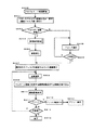
本実施の形態例のテレビ受像機本体1は、メインスイッチONにより実施の形態1と同様テレビモードで立ち上がり、モード選択の割込を可能とした後、後述するテレビモード処理を実行しテレビ放送を聴視可能な状態とする。従って、テレビ受像機本体1は、テレビリモコン3のメニューボタン45(図31)が押されるとモード選択処理を割込処理する。
【0142】
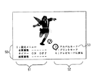
モード選択処理の動作を図32のフローチャートで説明する。この処理はテレビ受像機本体1の制御部であるCPU1hが行う処理である。メニューボタン45が押されると、テレビ表示部2に表示されているテレビ放送受信画像に図33のメニュー50が重畳表示される(S301)。表示されたメニュー50には、通常のテレビ操作用メニュー51に加えてアルバムモードメニュー52も含まれている。テレビ操作用メニュー51は、通常のテレビ操作を行うためのメニューで、選択されたメニューに従ってテレビ受像機本体1内で処理される。なお画質調整など前記メニューの一部はアルバムモードでも有効である。
【0143】
アルバムモードメニュー52には2つのサブモードすなわち「アルバムモード」、「プリントモード」と「テレビモードに戻る」が含まれている。アルバムモードメニューの前記2つのサブメニューは、画像蓄積装置7に対するもので、これらが選択されると、テレビ受像機本体1はそのメニューに応じて画像蓄積装置7、或いは画像蓄積装置7を介してプリンタ9と信号を送受信して画像蓄積装置7にアルバムモード処理、プリントモード処理や電源のON/OFFを行わせる。
【0144】
使用者によるモードの選択は、テレビリモコン3の選択ボタン46で所望のモードにカーソル53を合わせ、決定ボタン47を押下することにより行われる。S302では、選択されたモードがどのモードであるかを判別し、テレビモードであればS303のテレビモード処理に進む。アルバムモードまたはプリントモードであればS304に進み、画像蓄積装置7の電源をONにしてS305に進む。S305では選択されたモードがプリントモードかアルバムモードかを判断し、アルバムモードであればS306のアルバムモード処理に進む。プリントモードであれば、S307に進んでプリンタ9の電源をONとし、または画像蓄積装置7にプリンタ9の電源をONとさせてS308のプリントモード処理に進む。なお、S304、S307で画像蓄積装置7及びプリンタ9の電源が既にONになっているときは何もせず次のステップに進む。
【0145】
<アルバムモード>
次にアルバムモードすなわち画像蓄積装置7の動作説明をする。 図34はアルバムモード動作のフローチャートを示す。
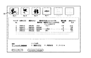
図33のように画面表示されたメニューの中からアルバムモードが選択されと、画像蓄積装置7のCPU4eはテレビ受像機本体1のCPU1hに信号を送り、AV出力制御部1eからテレビ表示部2に出力する画像をテレビ放送受信画像から画像蓄積装置の画像に切替え、画像蓄積装置7の記憶部4fに保存されている全フォルダをフレームメモリ106に読み出し、テレビ表示部2に全フォルダ情報を一覧表で表示する。同時に画像検索モードメニューも表示する。その時のテレビ画面表示の一例を各フォルダの代表画像と共に図35に示す。 なお、図35において前記フォルダ情報には各フォルダの代表画像も含まれ、前記テレビ表示画面の一部に代表画像30がフォルダNo.と共にフォルダNo.順に表示される。表示された代表画像を見てフォルダの選択ができるので、的確に所望のフォルダを選択することができる。
【0146】
アルバムモード処理中のメニューには図35に示すように「テレビモードに戻る」を表示しておき、テレビ放送を鑑賞したくなったときいつでも「テレビに戻る」ボタンを押すことにより、直接テレビ放送受信画像に戻ることができるようにしてある。
テレビ表示部2に表示された全フォルダ情報は、撮影時に作成されたフォルダ、また記憶部4fに保存する際に作成されたフォルダの階層に関係なく撮影年月日の新しいフォルダ順に並べられている。所望のフォルダは、テレビリモコン3の選択ボタン46によりフォルダNo.単位で選択することができ、決定ボタン47により所望フォルダが確定される(S205)。また、このテレビ表示部2に表示されたフォルダ一覧表にはソート条件も同時に表示されており、テレビリモコン3の選択ボタン46により該当するフォルダを選択し、決定ボタン47を押すことによりソート条件を選択することができる。
【0147】
前記選択操作により、選択された所望フォルダに対応する代表画像が縁取られる、或いはより明るいハイライト表示されるなどの方法によって他の画像と区別される。
また、画像蓄積装置7内に記憶された大量の画像の中から過去に作成したフォルダや画像を検索するために検索メニューが設けられており、必要に応じて検索を行うことができる。フォルダ/画像検索メニュー表示の画像検索を選択するときにはテレビリモコンのチャンネルボタンにより「0」を押すことにより行われる(S202)。
【0148】
ステップS205やS202にて所望フォルダが確定されると選択されたフォルダ内の画像データのヘッダ部に保存されている圧縮画像データ(サムネイル画像)がフレームメモリに読み出され、D/A変換され、9つの小画面としてテレビ表示部に表示される(S207)。 図36はS207でのテレビ表示部に表示された例を示したものである。
【0149】
テレビリモコンによるサムネイル画像の表示、選択の一例として次のようにして行うこともよい。テレビリモコン3にはテレビのチャンネル選択を行う数字ボタンが設けられている。
現在一般に多く使用されているテレビリモコンの前記数字ボタンは1から12である。そこで本発明の画像蓄積装置7は、テレビリモコン3のチャンネル数字ボタンの数の情報を受け取り、サムネイル画像を表示する際、チャンネル数字ボタンの数と同じ数及び配列でサムネイル画像を表示する。すなわち、チャンネル数字ボタンが12であれば12個のサムネイル画像を表示し、チャンネル数字ボタンのテレビリモコン配列位置と同じ配列位置にサムネイル画像を表示する。そして、表示中のサムネイル画像中の選択は前記数字ボタンで選択するサムネイル画像の番号に一致する数字の数字ボタンを押下する。
【0150】
ところで、画像蓄積装置7に記憶されたデータから対象画像として指定されたフォルダ中の各画像には一連の番号が付されており、サムネイル画像表示画面にその番号が付加表示されている。現在表示されていないサムネイル画像を前記番号をチャンネルボタンで指定することにより、その画像にジャンプして表示することができる。
【0151】
本実施の形態では1から12チャンネルを有するリモコンで説明したが、チャンネル数にはとられない。むしろテレビの多チャンネル化に対応して前記数字ボタンの数が今後増えると予想され、テレビリモコンのチャンネルボタンとテレビ表示画像と対応づけて画像選択操作することはますます画像選択操作性の点で効果的となる。
【0152】
ステップS202にてフォルダ/画像検索が選択されるとS203の検索条件設定処理が行われる。条件設定が終了するとS204の検索実行処理が行われ、ステップS207に移る。ステップS203の検索条件設定処理については後述する(図37)。
次に図36の画面表示された画像を選択し、アルバム鑑賞する操作について説明する。
ステップS208はS207で画面表示された画像の中から所望の画像を選択するステップである。画像の選択は、テレビリモコンの選択ボタン46により選択し、決定ボタン47により確定される。確定されるとステップ209に進み、選択されたサムネイル画像に対応する鑑賞画像をハードディスク4fからフレームメモリに読出し、ステップS210でD/A変換された後テレビ画面に表示する。テレビ表示部に表示された第1画面(9小画像)で所望の画像が見つけられなければ、テレビリモコン音量ボタン42により次画面送り操作が行われる(S211)。
【0153】
以上の操作により、所望の画像をハードディスクから読出し、テレビ表示部2の画面上に表示され鑑賞することが可能となる。
ステップS211では鑑賞した画像をプリントすると判断するときには画面メニュー表示されているプリントボタンをテレビリモコンの選択ボタンにて選択し、決定ボタンを押すことにより確定する。
【0154】
なお、モード選択(図32)の説明においてプリントモードが選択された場合にプリンタの電源をONとすると説明したが、図34のS211〜S213に示したようにS211でプリントする画像が確定されプリンタにプリント実行が指示されるときにプリンタがOFFであればプリンタの電源がONとされるようにしても良い。前記プリント実行指令が出力されたときプリンタの電源をONとする信号が出力されても良いし、前記プリント実行指令がプリンタの電源をONとする信号を兼ねても良い。
【0155】
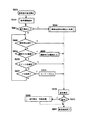
次にステップS203検索条件設定処理について説明する。 図37は検索条件設定処理の操作を示すフローチャートである。また図38はステップS220でのテレビ表示部2に表示された検索条件設定メニューである。
検索条件項目としては、撮影時に撮影されると自動的に付与されるコマ番号、撮影年月日時刻など、撮影者自身が入力したタイトル名やメモなどのテキストデータ、さらに充電年月日などがハードディスクの各フォルダに格納されている。実施の形態で示したタイトル名や撮影者名は撮影時にメディアに作成されるフォルダ名であり、ハードディスク上にそのままの名でフォルダ作成される。本実施の形態では検索条件項目としてハードディスクのフォルダ番号、充電年月日、撮影年月日、撮影者名、タイトル・メモが選択されている。
【0156】
ステップ221はハードディスクに格納されている過去に作成した検索条件をテレビ画面上に読み出すか否かを決めるための操作である。この操作は銀塩写真のアルバム整理で過去に作成したアルバムを取り出す操作に相当する。ステップS221の操作方法としては、2つの操作が選択できるようになっている。1つ目の操作は操作しなければ検索条件初期設定されている既定値に基づいて選択操作できるようになっており、テレビリモコン選択ボタンにより順次選択し、決定ボタンより確定していく操作である。2つ目の操作は、選択メニュー表示されている「アルバム名読出し」をテレビリモコンの選択ボタンにより選択し、決定ボタンにより確定することにより行われる操作である。
【0157】
まず第1の操作法は、ステップ223からS230まで各検索条件項目(フォルダ)について順次メニュー指示に従って入力、選択していく操作である。ステップS223の撮影者名フォルダの選択項目として予め登録されている選択項目を選択することになる。図38には検索条件設定メニュー表示画面を示す。図では、TARO、HANAKO、ICHIROと家族3名登録表示されており、HANAKOを選択した場合を示している。この選択項目についてはステップS232の条件保存登録処理(アルバム登録)で後述する。
【0158】
次のステップS224では検索しようとする撮影年月日範囲を入力する操作であり、S225で入力操作が行われる。この入力操作はテレビリモコンのチャンネルボタンにより数値選択し入力することにより行われる。ステップS226のタイトル名条件項目では先のステップS223と同様予め登録してある選択項目を選択する。ここでのタイトル名は撮影時にメディアに作成されるフォルダと対応させて登録するようにすることが可能である。ステップS227のメモ検索は撮影時やアルバム編集時にテキストデータで作成されたメモを部分一致検索で全フォルダにわたって検索することが可能である。そのキーワード入力操作S228は、テレビ表示部2の画面上にメニュー表示されている文字作成コード表を選択し表示して行われる。画面上の文字作成コード表上でテレビリモコンの選択ボタンと決定ボタンを押すことにより検索しようとする文字を作成する。 なお、文字入力は画像蓄積装置7のCPUに不図示のキーボード装置やペン入力装置などを接続して行ってもよい。
【0159】
第2の操作法は、ステップS222の検索条件設定読出し処理(アルバム読出し)によりハードディスクに保存されている検索条件、すなわち過去に作成したアルバム名を読み出す作業である。図39はアルバム名検索処理のフローチャートを示す。
ステップS222はテレビ画面上に表示されているアルバム名読出しモードをテレビリモコンの選択ボタンを押すことにより開始される。ステップS240にてハードディスクのアルバム名フォルダに格納されている検索条件の全内容を読出し、テレビ表示部の画面上に一覧表示させ、フォルダ選択可能モードとなる。図40はアルバム名一覧の一例を示す。このモードにおいても図35と同様メニュー表示されているアルバム名入力検索モードを選択することができる。ステップS242以降はアルバム名を入力させるフローであり、S246以降は一覧表示されているアルバムファイルをテレビリモコンの選択ボタンにより選択し、決定ボタンとにより確定するフローである。
【0160】
以上の操作により、所望のアルバムを検索することが可能となり、これら一連の検索結果がステップS244で表示される。
次に検索条件設定された結果をアルバム名やメモを付けて保存する処理動作である図37のステップS232の処理について説明する。
図41は検索条件の保存(アルバム保存)及び条件選択の登録処理のフローチャートである。図38の表示された選択メニューのアルバム保存モードをテレビリモコンの選択ボタンにより選択し、決定ボタンにより確定することにより処理が開始される。
【0161】
ステップS250ではアルバム名の撮影年月日や画像IDなどの検索条件項目や各項目における選択項目の追加や削除などがあるか否かあればステップ251に進み、なければアルバム保存のステップS257へと進む。S257はハードディスクにファイルとして格納するためのアルバム名を入力する操作である。アルバム名入力はテレビ選択メニュー表示されている文字コード表モードをテレビリモコンのチャンネルボタンで選択し、決定ボタンにより確定することによって行われ、ハードディスクのアルバム名フォルダにファイルとして保存される。
【0162】
またステップS250において条件項目・選択項目の削除や追加登録があるときには、図38の選択メニュー表示されている条件項目・選択項目の削除追加をテレビリモコンのの選択ボタンで選択し決定ボタンにより確定することにより行われる。ステップS251からS256までは検索条件項目及び選択項目の削除操作の処理である。削除項目がなければステップS257の検索条件の選択項目の設定登録処理モードに進む。図42は一連操作のフローチャートの一例を示す。
【0163】
この処理は図38で示されている検索条件設定画面の検索条件では撮影者名、撮影年月日、タイトル名、メモなどの項目が示されているが、これ以外に画像IDや撮影条件などについての項目を追加登録する場合に行われる操作である。
ステップS260では登録する検索条件項目の数を入力し、S263にて項目名「画像ID」を入力する。ステップS264では項目名「画像ID」の選択項目、例えば「99041501」、「99040403」「98040203」などを入力する。これら入力操作はまず画面選択メニュー表示されている文字コード表を選択する。「画像ID」、「99041501」、「99040403」「98040203」などの文字は画面表示されている文字コード表をテレビリモコンのチャンネルボタンにより作成され、決定ボタンで確定される。 以下入力された検索条件項目数、選択項目数まで順次同様な操作を行うことにより検索条件項目の設定登録処理が行われる。
【0164】
このように本発明では一般家庭で普及しているテレビリモコン操作により画像蓄積装置7を起動できるため、画像蓄積装置7専用テレビリモコンは不要となる。また一連の操作がテレビ表示部の画面上に表示選択メニューとして表示されてい
るため、機械操作が不慣れな人にも簡単に操作できるように配慮されている。
【0165】
なお、図36のS250とS257との間に、前記操作で設定した検索条件によって検索された画像、即ち作成したアルバムに含まれる画像のサムネイルを表示させ、その中の任意の1画像を該アルバムの代表画像として選定・記憶するステップを追加し、図34のS240で表示させた図35のアルバム名一覧に、表示されたアルバム名に対応する代表画像を表示するようにすると、鑑賞したいアルバムをより的確に選択することができ好ましい。
(2)プリントモード処理
図33のテレビ表示部2の画面に表示されたメニューでプリントモードを選択したときの動作について説明する。
【0166】
プリントモード処理は、画像蓄積装置7に記憶された画像のうち所望の画像のプリントを出力するための処理である。図34の説明中のS207〜S212にプリント出力手順の一例を示したが、ここでは、より機能を高めた実施の形態例を示す。システムの構成は、前述実施の形態例と同じであるので同一符号を引用することで説明を省略する。
【0167】
なお、本実施の形態2によるプリントモード処理を行う場合には、S301でモード選択メニューを表示させると同時に、メニューボタン45が押された時のモードを前モードとして記憶しておく。S301で表示された図33のメニューのプリントモードを選択する。すると図32のフローにおいてS305でプリントモードであるか否かが判断される。ここではプリントモードが選択されているのでS307へ進みプリンタの電源をONとしてS308のプリントモード処理へ進む。
【0168】
(a)画像蓄積装置の記憶内容
デジタルカメラで撮影した画像データは全て画像蓄積装置7の記憶部7fに転送・記憶されている。前記記憶部7fに記憶されている画像データには、撮影時のデータを引き継いだ、若しくは前記記憶部7fに転送・記憶時に指定したフォルダ名又はフォルダ番号、ファイル名又はファイル番号が付されている。画像蓄積装置7に転送・記憶される各画像データには撮影時に付加されたコメント、例えば撮影日時、撮影時に入力した各種メモも含まれる。
【0169】
デジタルカメラによる撮影時、全画像にプリント出力する画像であることを示すプリント出力指示信号が付加される。前記プリント出力指示信号はデジタルカメラの操作により消去することができる。従って、前記画像記憶部7fに記憶されている画像データは、前記プリント出力指示信号付きの画像データと、プリント出力指示信号なしの画像データとが混在している。
【0170】
(b)プリント出力画面の選択
前記所望の画像は、デジタルカメラによる撮影時にプリント出力指示信号が付されることによる他、本プリントモード処理の中でアルバムモード処理の機能を用いて前述した検索操作を行って選択・表示した画像に対してプリント出力指示信号を追記、削除、変更することによって選択する。さらに、本プリントモード処理では、必要に応じて、プリントに付すコメントの設定やトリミング指定などのプリント条件の設定も行われる。コメントの設定、トリミング指定、プリント出力指示信号の追記、削除、変更の詳細については後述する。
【0171】
前記コメントの設定、トリミング指定、プリント出力指示信号に関する処理やプリント条件の設定は、前述したアルバムモード処理でも行えるようにしても良い。
(c)プリント出力
プリントモード処理の詳細を図43のフローで説明する。このフローの処理は画像蓄積装置7の制御部であるCPU7eが行う処理である。
【0172】
プリントモード処理が開始されると、画像蓄積装置7は、図44のプリントメニュー54をテレビ表示部2に表示中の画像に重畳して表示させる(S311)。図44では前モードがアルバムモードでサムネイル表示画面に重畳表示された例を示したが、前モードがテレビモードの場合はテレビ放送画面に重畳表示される。
【0173】
プリントメニュー54には、「逐次プリント」、「一括プリント」、「プリント条件設定」が含まれる。S312では選択されたメニューに応じて処理の流れを分岐制御する。
逐次プリントが選択された場合はS313に進み、前述のアルバムモードの機能によって、プリント出力する画像が選択され、その鑑賞画像がテレビ表示部2に表示されると共に、プリント開始を指示するメニューが重畳表示される(S314)。ここで、必要に応じて表示された画像に対してトリミング指定(S315)、コメント入力(S316)、プリント条件設定(S317)が割込処理可能である。各割込処理については後述する。なお、点線枠内の上記S313〜S314は前述したアルバムモード処理の機能である。
【0174】
決定ボタン47の押下によってプリント出力が開始され(S318)、表示中の画像がプリント出力されて(S319)、次の画像が選択されて(S320)、S313に戻る。以下、S313からS320のステップを繰り返すことによりプリントする画像を逐次表示させながらプリント出力が行われる。
S312で一括プリントが選択された場合は、S321に進み、アルバムモードの機能によってプリント出力したい画像が含まれるフォルダが選択される。前記フォルダの選択は、フォルダ名で検索/指定されたフォルダ、又は検索された画像を含むフォルダとして選択される。検索された画像が複数のフォルダにある場合は一時的に自動生成されたプリント出力用フォルダに検索された画像の管理情報が書き込まれる。前記フォルダが生成されたときは、該フォルダがプリント出力対象フォルダとして選択される。この間、サムネイルの表示、鑑賞画像の表示がアルバムモードの機能によって適宜行われる。また、一括プリント開始のメニューが重畳表示され、決定ボタン47の押下によってS322に進み一括プリント出力が開始される。
【0175】
一括プリントでは、選択されたフォルダ中の画像で、プリント出力指示信号が付された全画像が、指定された枚数、順次プリント出力される。
S323では、モード選択のためにテレビリモコン3のメニューボタン45が押された時のモード(前モード)に応じて、以降の処理の流れを分岐制御する。前記前モードがテレビモードであった場合はS331に進み、テレビモード処理を実行する。つまり、通常のテレビとしての動作を行うと同時に、裏モードでプリント出力を続行する(S332)。そして、プリント出力の進捗状況(残り出力枚数など)やプリント終了を示す信号をテレビモード処理に割り込み出力する(S333)。そして、S311に戻りテレビモード処理を継続する。
【0176】
前記前モードがアルバムモードであった場合は、S324に進み、現在プリント出力中の画像を表示する。同時に、プリント出力の進捗状況を重畳表示する(S325)。そして、全対象画像のプリント出力が完了したら(S326)、一括プリント完了を表示して(S327)、処理を終了する。
あるいは、S324でプリント出力対象フォルダに含まれるプリント出力指示信号の付された画像のみをサムネイル表示して、プリント出力が終了した画像のサムネイル表示を終了することによってS325の進捗状況表示としても良い。
【0177】
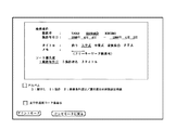
S312でプリント条件設定が選択された場合はS341に進み、図45のプリント条件設定メニューが表示中の画像に重畳表示される。適宜のメニューを選択することによって、プリント画質、用紙の種類、プリント枚数、コメント出力要否、コメント設定などのプリント条件を入力・設定してS311に戻り、再びプリントメニューを表示して他のメニューが選択されるのを待つ。以降の一括プリントは前記設定された条件に従って行う。逐次プリントの場合もS317で異なる条件が指定されなければこの条件で行う。S317のプリント条件設定の割込処理はS341の処理と同じであるが、ここで設定された各種条件は次のプリント出力にのみ有効であり、プリント出力完了後に元の設定に戻される。なお、各項目には最も一般的と思われる条件がデフォルトで設定されている。
【0178】
(d)テレビモード処理
S331のテレビモード処理とS303のテレビモード処理とは同様の処理であり、一括プリント中にテレビ放送の視聴を可能とするためのものである。この処理はテレビ本体1のCPU1hが行う。以下、テレビモード処理を図46のフローにより説明する。
【0179】
テレビモード処理が開始されると、テレビ受像機本体1はS351で通常のテレビ放送受信動作を行い、S353で図43のS333の、画像蓄積装置7のCPU7eからのプリント進捗状況、プリント終了の割込信号S352があったかどうかを判断する。そして、前記割込信号S352が無ければS355に進む。前記割込信号S352があった場合はS354で、前記画像蓄積装置7のCPU7eから受けたプリント進捗状況やプリント終了の表示をテレビ表示部2に所定時間だけ重畳表示させてS355に進む。そして、S355ではテレビ受像機本体1の電源OFFを検出する処理を行い、電源OFFが検出されなければS351に戻りテレビ放送受信動作を継続する。
【0180】
S355でテレビ本体の電源OFFが検出された場合は、S356に進み裏モードで一括プリント処理中であるか否かを判断する。前記処理中でなければS360に進み、テレビ受像機本体1、画像蓄積装置7、プリンタ9の電源をOFFして処理を終了する。前記処理中である場合はS357に進み、テレビ受像機本体1のテレビ受像回路への給電とテレビ表示部2の電源をOFFとする。画像蓄積装置7、プリンタ9の電源はそのままなので、S358でプリント出力の終了を検出するまで一括プリント出力が継続され、プリント出力の進捗状況や終了の信号がテレビ受像機本体1に割込出力される。そして、S358でプリント出力の終了を検出したらS359で画像蓄積装置7、プリンタ9の電源をOFFし、テレビ受像機本体1の残り部分の電源をOFFして処理を終了する。
【0181】
なお、S356以降の処理は主に画像蓄積装置のCPUで処理し、必要な信号を必要に応じてテレビ受像機本体、プリンタに出力して上記と同じ動作を果たすようにしても良い。
S357のテレビ受像機本体1のテレビ受像回路の電源OFFに際し、テレビ本体1はS358以下の処理が続行されたことを記録する。そして、次回テレビ受像機本体1の電源がONされた時に、プリンタにプリントがある旨の表示を行う。その際、プリンタ9が作動中か、停止しているか(電源OFFを含む)を確認し、作動中であればプリントの進捗状況を表示し、停止中であればプリント完了を表示することが好ましい。
【0182】
なお、プリンタは作動中、テレビ放送の視聴に支障をきたす電気ノイズや騒音を発生することがある。そこで、テレビモード処理を該モードに入った時点で未プリント出力分のプリント出力を中断しテレビ放送受信動作のみを行うようにして、支障無くテレビ放送を視聴できるようにし、テレビ受像機本体1の電源がOFFされたら又はテレビモード以外のモードとされたら前記テレビモード処理を再開するようにすることができる。
【0183】
(e)プリント出力指示信号に関する処理
プリント出力する画像の選択・指定はデジタルカメラ側で行うほか、アルバムモードでも行うことができる。即ち、図32のアルバムモードでの画像選択(S313)、アルバムモードでのフォルダの選択(S321)にプリント出力画像の選択機能が含まれている。
【0184】
例えば、画像鑑賞のために画像選択機能で指定した、目的とする画像データ範囲、例えば特定のフォルダ中の画像や撮影日時が指定した日時範囲の画像のサムネイルを表示する(図36)と、既にデジタルカメラでプリント出力指示信号を付された画像31にはプリント選択マークP1(32)が画像の右側方に同時に表示される。プリント出力指示信号が付されていない画像33にはプリント選択マークの表示がない。
【0185】
既に述べた如く、撮影時に自動的にプリント出力指示信号が付されるので、デジタルカメラを操作してプリント出力指示信号を削除しない限りデジタルカメラから読み込まれた画像にはプリント出力指示信号が付されている。これにより、プリントモードでプリント出力するときの操作手順が減り、簡素化される。
サムネイル表示中の任意の1画像を前記画像選択機能で選択して表示させた鑑賞画像にも前記プリント選択マークP1が同時に表示される。前記プリント選択マークのPに続く数字はプリント出力する枚数を示す数字であり、デジタルカメラで付加されるプリント出力指示信号P1はプリント出力1枚を意味する。
【0186】
そして、画像蓄積装置7は、サムネイル表示で選択した画像及び鑑賞画像に対してテレビリモコン3(図31)の操作によって前記プリント出力指示信号を付加、変更、消去することができる。具体的操作方法は、対象とする画像を選択/表示して、テレビリモコン3の音量ボタン42の+ボタン42A、−ボタン42BでPに続く数字を増減させる。図31の画像34には前記の操作により変更したプリント出力2枚を意味するプリント選択マークP2(35)が表示されている。P0でプリント出力信号が消去されプリント選択マークの表示が消える。プリント選択マーク無表示(即ちP0)の時、+ボタン42Aを押下するとP1が表示される。
(f)トリミング
アルバムモードで表示中の鑑賞画像に対して、ズーミング機能を利用してトリミング指定をすることができる。ズーミング機能は鑑賞画像表示中にチャンネルボタン43が押下されることで起動され、+のチャンネルボタン43Aの押下によってズームアップされ、−のチャンネルボタン43Bの押下によってズームダウンされる。そして、ズーミングして表示中の画像範囲がプリント出力範囲となる。ズーミング画像を表示して決定ボタン47を押下するとトリミング範囲及び倍率がその画像の画像データに追加記録される。
【0187】
この情報が付された画像を表示すると画像の右側にトリミング条件が記憶されていることを示すマークT(36)が表示される。そして、選択ボタン46で表示画像を順次表示させる際、元の画像に対して、その画像データに追加記録された前記トリミング条件によってトリミング処理を行って作成したトリミング画像を元の画像の後に表示する。従って、後日でも同一のトリミング画像のプリントを作成することができる。なお、前記トリミング画像の作成処理は元の画像を表示すると同時に開始し、トリミング画像の表示に要する見かけ時間を短縮する。
【0188】
画像蓄積装置7の記憶部7fに追加記憶するデータはトリミング条件のみなので、トリミングされた画像を記憶する場合に比べ、追加記憶するデータ容量が小さくて済む。
(g)コメント出力
S341のプリント条件設定でのコメントA、Bを設定しコメント出力要を選択すると、その画像データに付加されたコメントが図47に示すように画像の範囲外にプリントされる。この場合、アルバムモードで表示した鑑賞画像60の画像表示領域61の下方に設けられたコメント表示部62に鑑賞画像に付されたコメントが表示される。前記コメントとしては、撮影日時など撮影時に付加されたコメントA(63)の他、アルバムモードにおいてテレビリモコン3を用いて追加したコメントB(64)がある。前記コメントA、Bは修正することができる。
【0189】
即ち、撮影時に付されたコメントAがあれば鑑賞画像の前記コメント表示部62に表示される。そして、コメントBの表示位置にカーソルが表示され、この位置にテレビリモコン3で追加コメントBを入力することができる。表示中のコメントの任意の位置にカーソルを移動して入力すれば表示中のコメントは上書き修正される。
【0190】
テレビリモコン3によるコメントの入力は、携帯電話、PHSによる文字入力と同様の方法とすることができ、例えば、あ、か、さ、た、な、…わの各行にチャンネルボタンの数字1、2、3、4、5…0を対応させ、これらの数字を押す回数をあ、い、う、え、おの各段に対応させる。そして各文字毎に決定ボタンで確定し、決定ボタン47を2回連続して押すことでコメント入力を終了する。例えば、カメラは、2、決定、7777、決定、9、決定、決定とテレビリモコン3のチャンネルボタン48、決定ボタン47を操作することで入力される。更に、適宜仮名−漢字変換機能を持たせても良い。
【0191】
なお、S341のプリント条件設定で設定したコメントBは、設定後にプリント出力する全てのプリントに付されるので、同一のコメント付す場合に便利である。一方、逐次プリントのプリント条件入力(S317)で設定したコメントBはその画像に対してのみ有効であるので、各画像に異なるコメントを付す場合に用いると良い。
【0192】
なお、鑑賞画像表示中にテレビリモコン3の数字ボタン48による上記コメント入力操作をすることによって、プリント条件設定処理(S317)中のコメント入力機能(S316)を起動させることができる。
(実施の形態3)
図48は実施の形態3の外観斜視図であり、画像蓄積装置4の構成は図1の実施の形態1と同じである。一方、デジタルカメラ8は図29の実施の形態2と同じになっている。
【0193】
図48の実施の形態3の特徴は複合充電器12にある。複合充電器12と画像蓄積装置4を接続するケープル12bは、IEEE1394規格によるもので、図1のケーブル5bと同じものである。一方、複合充電器12とデジタルカメラ8を接続するケーブル12cは図29のケーブル8aと同様、給電路と信号伝達路が一本にまとめられた専用ケープルになっている。また、商用電源が供給されるケープル12aは図1のケーブル5aと同じものである。その他の構成は、図1の実施の形態1と同様なので説明を省略する。
【0194】
図49は、実施の形態3のシステム構成図であり、複合充電器12において、接続ターミナル8cにはケーブル12cが接続されるが、このケーブル12cは充電路12dとIEEE1394に準拠した信号伝達路12eが一本のケーブルとしてまとめられた専用規格のものである。これと対応して複合充電器12は、IEEE1394に準拠した信号端子と充電端子が一つにまとめられた専用規格の接続ターミナル12fをもつ。接続ターミナル12fの充電端子はACアダプタ12gに接続されると共に、信号端子はIEEE1394端子12hに接続されている。IEEE1394端子12hには、IEEE1394規格によるケーブル12bが接続される。また、ACアダプタ12gにはケーブル12aを介して商用電源が供給される。
【0195】
実施の形態3においては、複合充電器12がデジタルカメラ8専用の付属品となり、ACアダプタ12gはデジタルカメラ8に合った専用の出力電圧を供給する。デジタルカメラ8が異なれば、これに対応する異なった電圧の複合充電器12を供給することによって、画像蓄積装置4は汎用品となる。また、複合充電器12は、通常の充電器に対し、画像蓄積装置4に接続するためのIEEE1394端子を付加すると共に、デジタルカメラ8との接続端子として充電端子と信号端子を複合した接続ターミナルを設け、これらの間の配線するだけで構成できるので、格別のコストアップを要しない。
(実施の形態4)
図50は実施の形態4の外観斜視図である。この実施の形態では、図1の実施の形態1における各機能がひとつのテレビ受像機としてまとめられている。図1との関係で詳細に説明すると、まず実施の形態1ではテレビ受像機本体1とテレビ表示部2が別体であったが、図50の実施の形態4は通常のテレビ受像機として構成されている。すなわち、箱体13には、テレビ表示部14とともにチューナーなどからなるテレビ受像機本体が収められている。箱体13にはさらに図1の実施の形態1における画像蓄積装置4に対応する機能も組み込まれている。
【0196】
実施の形態4では、実施の形態1におけるテレビ受像機本体1と画像蓄積装置4に対応する機能が一つのテレビ受像機としてまとめられているので、画像蓄積装置4のためのハードディスクなどからなる大容量の記憶部4fには、画像データの記憶だけでなく、テレビ受像機本体1の制御のためのプログラムを記憶させることも可能である。
【0197】
15はデジタルカメラ収納スペースであり、扉16を閉じることで、収納されたデジタルカメラを密閉し、防塵を図る。収納スペース15は、テレビ受像機の熱や電磁波からの影響が少ない位置に配されると共に、収納スペース壁も必要に応じ耐熱および耐電磁波構造とされる。
図50におけるステーション17は、図1のステーション5に対応するもので、デジタルカメラ18専用のものであり、デジタルカメラに合わせて交換できる。ステーション17は規格化された給電コネクタおよび信号コネクタを持ち、収納スペース15の底部に装着することでこれらのコネクタがテレビ受像機本体の対応するコネクタと接続される。収納スペース15は各種のカメラおよびステーションに対応するため充分の広さを持っており、ステーションとの間のコネクタとその配置だけが規格化されている。
【0198】
実施の形態4における使用状況を説明すると、所望のステーション17が収納スペース15に装着されている状態が待機状態であり、デジタルカメラ18は例えば戸外などにおいて使用される。帰宅後、扉16を空けて常の収納場所である収納スペース15のステーション17の上にデジタルカメラ18を載せて収納し、扉16を閉じれば基本操作は終了である。このような使用環境では、まず、デジタルカメラの収納場所が一定のところに定まるので、紛失のおそれがない。また、収納中において、自動的に充電および画像データの吸い上げが行われ、メモリが空になる。したがって、次回の使用時には、デジタルカメラを探し回ることもなく、また、電源および撮影可能メモリ容量の心配をする必要もない。さらに、過去に撮影した画像は全て間違いなくテレビ受像機中の画像蓄積装置に蓄積されているので、フィルムカメラの場合におけるネガやプリントの散逸といった事態も生じない。テレビ表示部14で確認しながら画像蓄積装置の中をサーチすることによって、所望の画像は必ず発見できる。なお、画像蓄積装置は電子ファイルであるから、適宜の効率良いサーチ手法の実施が可能である。
【0199】
図50の実施の形態4では、さらにプリンタ機能と通信機能がテレビ受像機の箱体13内に組み込まれている。19は通信機能のための商用電話線へのモジュラージャックであり、テレビ受像機内の通信機能に対応していると共に電話機11にも通じている。20はプリンタのプリント排紙口であり、21はプリント用紙供給部の蓋である。以上のようなテレビ受像機の全機能に対して、ケーブル22から商用電源が供給される。
【0200】
図50の実施の形態4の機能の詳細や使用操作の詳細は、これまで説明した各実施の形態と基本的に同じであり、テレビリモコンにより操作可能である。
なお、実施の形態4では、図50からは見えない位置に、実施の形態1におけるカードスロット4sに対応するカードスロットが設けられており、デジタルカメラ18の収納によるほか、このカードスロットに挿入されたカードメモリからデジタル静止画像データを入力することも可能である。
(実施の形態5)
本発明の他の実施の形態5について説明する。
【0201】
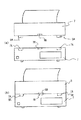
これまでのいずれの実施の形態も画像蓄積装置とプリンタとは別体となった構成であるが、本実施の形態5では画像蓄積装置とプリンタと一体的に構成した例である。他の構成についてはこれまでの実施の形態のいずれかと同じである。
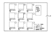
図51(a)に示したように、プリンタ9は画像蓄積装置7から独立したユニットで構成されており、画像蓄積装置7の上面に載置される。画像蓄積装置7の上面にはプリンタ9を所定の位置に安定して載置するためにプリンタ9の下面の突起部9Aを収納する窪み7Aなどの位置決め手段が設けられている。さらに画像蓄積装置7の上面とプリンタ9の下面には、画像蓄積装置7とプリンタ9との間で画像データや制御信号を授受するコネクタ接点やフォトカップラなどの信号伝達手段7B、9Bが設けられている。従って図51(b)に示したように、プリンタ9を画像蓄積装置7の所定の位置に載置するだけでプリント出力可能な状態になる。
【0202】
プリンタ9と画像蓄積装置7とが一体的に設置されるので設置スペースが小さくて済む。また、分離することもできるので、一方が故障した場合にはそちらだけを修理・交換可能であるというメリットがある。
【0203】
【発明の効果】
本発明によれば、デジタルカメラにて撮影した静止画像を家庭用のテレビ受像機を用いて、銀塩写真アルバムを鑑賞すると同様の容易さで検索し、鑑賞、プリントすることができると共に、テレビ放送の視聴も最大限可能とされる。
【図面の簡単な説明】
【図1】実施の形態1のシステム外観斜視図。
【図2】実施の形態1のシステム構成図。
【図3】画像蓄積装置の構成ブロック図。
【図4】ステーションの構成ブロック図。
【図5】デジタルカメラの構成ブロック図。
【図6】画像蓄積装置の動作を説明する第1のフローチャート。
【図7】画像蓄積装置の動作を説明する第2のフローチャート。
【図8】信号受信制御動作を説明する第1のフローチャート。
【図9】信号受信制御動作を説明する第2のフローチャート。
【図10】信号受信制御動作を説明する第3のフローチャート。
【図11】画像蓄積装置内の記憶部に作成されたフォルダの一例。
【図12】接続解除割り込み処理動作を説明するフローチャート。
【図13】図7とは別の信号受信制御動作を説明する第1のフローチャート。
【図14】図7とは別の信号受信制御動作を説明する第2のフローチャート。
【図15】図7とは別の信号受信制御動作を説明する第3のフローチャート。
【図16】実施の形態1で用いたテレビリモコン。
【図17】テレビ受像機本体の基本動作フローチャート。
【図18】実施の形態1のアルバムモードの基本フローチャート。
【図19】実施の形態1のデータ取り込み割り込みフローチャート。
【図20】実施の形態1のアルバムモード動作フローチャート。
【図21】実施の形態1の画面送り動作フローチャート。
【図22】実施の形態1の階層変更操作を説明するテレビ表示部の画面表示例。
【図23】実施の形態1の階層変更フローチャート。
【図24】実施の形態1の階層変更操作における選択フローチャート。
【図25】実施の形態1のマイ・アルバムモード動作を説明するフローチャート。
【図26】実施の形態1の検索動作を説明するフローチャート。
【図27】実施の形態1のプリント処理動作を説明するフローチャート。
【図28】実施の形態1のアルバムモード終了フローチャート。
【図29】実施の形態2のシステム外観斜視図。
【図30】実施の形態2のシステム構成図。
【図31】実施の形態2で用いたテレビリモコン。
【図32】実施の形態2のモード選択割り込み動作を説明するフローチャート。
【図33】実施の形態2のテレビ表示部の画面表示メニュー例。
【図34】実施の形態2のアルバムモード処理動作を説明するフローチャート。
【図35】実施の形態2のテレビ表示部に表示された全フォルダ情報一覧表の一例。
【図36】実施の形態2のテレビ表示部に表示されたサムネイル画像の一例。
【図37】実施の形態2のアルバムモード処理時における検索条件設定処理動作を説明するフローチャート。
【図38】実施の形態2のテレビ表示部に表示された検索条件設定メニューの一例。
【図39】実施の形態2のアルバム名検索処理作を説明するフローチャート。
【図40】実施の形態2のテレビ表示部に表示されたアルバム名リストの一例。
【図41】実施の形態2の検索条件保存・登録処理の動作フローチャート。
【図42】実施の形態2の検索条件選択項目の登録処理の動作フローチャート。
【図43】実施の形態2のプリントモード処理の動作フローチャート。
【図44】実施の形態2のテレビ表示部に表示されたプリントモード処理メニュー。
【図45】実施の形態2のテレビ表示部に表示されたプリント条件メニュー。
【図46】実施の形態2のテレビモード処理の動作フローチャート。
【図47】実施の形態2のプリント出力された表示例。
【図48】実施の形態3のシステム外観斜視図。
【図49】実施の形態3のシステム構成図。
【図50】実施の形態4のシステム外観斜視図。
【図51】実施の形態5のプリンタ構成図。
【符号の説明】
1 テレビ受像機本体
2 テレビ表示部
3 テレビリモコン
4、7 画像蓄積装置
4a、7a テレビ受像機と画像蓄積装置とを接続する信号ケーブル
4b、7b テレビ受像機と画像蓄積装置とを接続する信号ケーブル
4e、7e 制御部
4f、7f 記憶部
4g、7g NTSC変換回路
5、12 ステーション
6、8 デジタルカメラ
9 プリンタ
10 電話通信用モデム
11 電話機[0001]
BACKGROUND OF THE INVENTION
The present invention relates to a system for accumulating digital still image data and viewing the image using a television receiver, and more particularly to a system for printing the image and an apparatus constituting the system.
[0002]
[Prior art]
A subject is photographed by a digital camera using a CCD (Charge Coupled Device) image sensor, and recorded as digital still image data (hereinafter sometimes referred to as image data or simply an image) on a recording medium such as a memory card or a floppy disk. To be done. These recording media have a limit to the number of images that can be captured. Therefore, in general, image data is transferred from these portable recording media to a personal computer having a large storage capacity and stored, and the image data stored by an input device such as a keyboard or mouse of the personal computer is searched for. So-called image filing devices (systems) and electronic album devices, which are displayed on a monitor screen for viewing, are widely used. As prior arts related to these, there are JP-A-62-295178, JP-A-7-282077, JP-A-7-182366, JP-A-11-32285, and the like. Further, as an electronic album system that can easily organize and search a large amount of image information stored in the home, there are, for example, Japanese Patent Laid-Open Nos. 63-142963 and 7-87432.
[0003]
Recently, however, there has been an increasing demand for more easily and easily storing and organizing images taken with television receivers used in ordinary households, and for immediately viewing and obtaining prints. It is coming.
One of the easy ways to view captured images is to connect a digital camera containing the captured image data directly to the AV receiver's AV terminal and display the captured image on the TV receiver's screen to enjoy memories. Things have been done.
[0004]
Furthermore, as a dedicated electronic album device, image data taken from a recording medium of a digital camera is transferred to a storage device having a large-capacity storage medium, such as a magneto-optical disk device, and the image data is stored therein. There is a device that can process arbitrary image data of the image and edit it like an album of a silver salt photograph or print it with a connected printer. As such an apparatus, for example, Olympus CAMEDIA VS100MO and Canon PHOTO STATION PA-200 are known. All of these devices are cord-connected to the AV terminal of a television receiver used in general homes, select an image to be viewed or edited with a remote control dedicated to the device, edit as necessary, and still images to be printed It is an appreciation / editing device.
[0005]
On the other hand, an increasing number of television receivers have a memory function capable of writing / reading images. A representative example of this prior art is Japanese Patent Laid-Open No. 10-248038. This publication discloses a television receiver that can store still images and moving images of a terrestrial television, a video tape, a still camera, etc. in a television image memory, and can read and display them by remote control operation.
[0006]
Furthermore, a television that prints image data converted and stored in a television image memory by a built-in printer in the television by a command operation of a television remote controller and displays on the television screen during printing is disclosed in JP-A-9-121313. It is disclosed in the gazette.
Further, as conventional techniques for controlling AV equipment via a television receiver using a remote controller, there are, for example, Japanese Patent Application Laid-Open Nos. 62-21379 and 9-120666. Japanese Patent Laid-Open No. 9-120666 intends to control a plurality of AV devices connected to a television receiver via a serial bus compliant with the IEEE1394 standard by using the television receiver as an AV control center. Furthermore, the media content menu of the connected AV device is displayed on the screen of the television receiver so that it can be selected.
[0007]
[Problems to be solved by the invention]
However, the ease of use of the conventional filing device (system) and electronic album device has not fully satisfied ordinary household users. For example, Japanese Patent Laid-Open No. 7-87432 requires an operation for transferring and storing images taken from a digital camera to a storage device of a personal computer, and a keyboard operation for viewing and printing the stored images. There is a problem that it is very troublesome for children, housewives, elderly people, etc., who are not familiar with it.
[0008]
In addition, a conventional still image viewing / editing device connected to the TV receiver's AV terminal for viewing and enjoying the captured image must use a remote control dedicated to the still image viewing / editing device in addition to the remote control of the television receiver. There is a problem that must be. Furthermore, there is a problem that it is not possible to easily switch to and display a television broadcast image at any time at any time, and it is necessary to remove the connection cable each time, which requires a very complicated operation. Since it takes a relatively long time to print an image, it is also a problem that a television broadcast cannot be viewed while printing.
[0009]
Further, in Japanese Patent Laid-Open No. 10-248038 of the prior art, an image memory built in the television receiver can be recorded / reproduced by a remote control and only album editing is possible. The memory capacity of the conventional television receiver is increased. This method is replaced with a large capacity, and with this method, it is difficult to perform an image viewing operation that satisfies the user.
Further, Japanese Patent Laid-Open No. 9-121313, which is a prior art, is intended for video currently being broadcast on TV or being input from TVR, and cannot be used for a large amount of still images taken with a digital camera. There is also a problem that the life of the entire apparatus is shortened because the printer including the component parts having a shorter life is integrated.
[0010]
SUMMARY OF THE INVENTION An object of the present invention is to provide an image appreciation system capable of searching and printing images taken by a digital camera with the same ease as appreciating a silver halide photo album using a home television receiver.
It is another object of the present invention to provide an image appreciation system that enables viewing of a television broadcast to the maximum when it is desired to make both an image print and a television broadcast.
[0011]
The present invention for realizing the above object is a television receiver having an album mode for displaying an image based on a still image signal from the outside and a television mode for viewing a television broadcast, and an image storage device to which a printer can be connected. , De A storage unit for storing digital still image data, an image output unit for outputting a still image signal based on the stored digital still image data to the television receiver, and a print command input for receiving a print command from the television receiver A print execution command output unit that outputs a print execution command for printing an image based on the stored digital still image data to the printer according to the input print command. A control unit for outputting a control signal for setting the television receiver in the television mode when the print execution command output unit outputs a print execution command; It is an image storage device characterized by having.
[0012]
Or a television receiver having an album mode for displaying an image based on a still image signal from the outside and a television mode for viewing a television broadcast, and an image storage device to which a printer can be connected. , De A storage unit for storing digital still image data; an image output unit for outputting a still image signal based on the stored digital still image data to the television receiver; and the stored digital still image data from the television receiver A control unit that receives an image designation signal that designates an image to be printed in the image based on the image, and a print execution command output unit that outputs a print execution command for printing the designated image to the printer When the print execution command output unit outputs a print execution command, a control signal for setting the television receiver to the television mode is output. This is an image storage device.
[0013]
In this case, the control unit may further receive an image cancel signal for canceling the designated image and a signal enabling the designation of the image from the television receiver.
The signal that enables selection of the image can be a signal that is output when the television receiver is set to the album mode.
[0014]
in front The control unit can output a control signal for setting the television receiver in the television mode when the print execution command output unit outputs a print execution command. The image storage device can maximize the time of the television mode with a simple operation.
[0027]
The installation space for the printer and the image storage device is small, and if one of them breaks down, only that can be repaired or replaced.
The print command input unit, print execution command output unit, control unit, image cancellation unit, signal output unit, print condition setting unit, and the like described above are configured by a CPU or the like in the example of the embodiment described in detail below. It is configured as a control unit of the image storage device. Of course, each part may be provided individually, or each part may be grouped and a control part may be provided for each group. Furthermore, an electric circuit designed to perform each function may be used.
[0028]
DETAILED DESCRIPTION OF THE INVENTION
(Embodiment 1)
(1) System configuration
1 and 2 are a system external perspective view and a system configuration diagram according to the first embodiment.
[0029]
In the television receiver according to the first embodiment, a television receiver
[0030]
The
[0031]
The TV
[0032]
The
[0033]
When the
[0034]
FIG. 2 is a system configuration diagram of
[0035]
When the mode change operation is performed by the TV
[0036]
The cable 5b according to the IEEE1394 standard is connected between the
The television receiver according to the first embodiment has been described in which the
[0037]
In the above example, the television signal converted by the
However, a digital signal that has not been converted into a television signal may be received via the
[0038]
It is also possible to directly transmit a signal from the
Further, the
(2) Each configuration and function
Next, each configuration and function of the image storage device, station, and digital camera constituting the system of the present invention will be described.
[0039]
FIG. 3 is a block diagram illustrating a configuration of the
The
The CPU 4e controls devices in the
[0040]
The card slot 4s is a device that reads an image or an audio signal from a card memory (compact flash, smart media, memory stick, etc.) attached to the
[0041]
The card driver 4p is a device that drives the card slot 4s in response to a command from the CPU 4e.
The storage unit 4f is a nonvolatile large-capacity hard disk that stores a large amount of image or audio signals. A program processed by the CPU 4e is also stored.
The storage unit driver 4n is a device that drives the storage unit 4f according to a command from the CPU 4e.
[0042]
An MPEG (Moving Picture Expert Group)
A JPEG (Joint Photograpfic Expert Group) decoder 4t is a device for expanding and reproducing still image data compressed and recorded by the JPEG method.
The
[0043]
The switch circuit 4q is a circuit that detects that a switch provided in the
The power supply circuit 4 r is a device that is connected to a commercial power supply (not shown) and supplies power to each device in the
The IEEE1394 interface 4j is a device for transmitting and receiving control signals, images, audio signals, and the like to and from the IEEE1394 interface mounted on the
[0044]
The
The
[0045]
The
FIG. 4 is a block diagram illustrating a configuration of the
The
The AC adapter 5e is a power supply device that is connected to a commercial power source (not shown) and supplies power to the attached
[0046]
The DSC connection connector 5j is a connector that is connected to the DSC connection connector 6n provided in the
[0047]
The
[0048]
The IEEE1394 connector 5c is a connector for connecting a cable 5b connecting the IEEE1394 interfaces mounted on the
[0049]
The LED 5i includes a memory LED 5k and a charging LED 5m. The LED 5i informs the user of the state of the card memory mounted in the
The
[0050]
FIG. 5 is a block diagram showing the configuration of the
The
The CPU 6h controls each device in the
[0051]
The
The IEEE1394 interface 6e is a device for transmitting and receiving control signals, images, audio signals, and the like to and from the IEEE1394 interface mounted on the
[0052]
The IEEE1394 connector 6d is a connector for exchanging signals with other devices having an IEEE1394 interface. Although not described in the embodiment, it is used when exchanging signals with the
[0053]
The AV connector 6m is a connector for outputting an NTSC-converted television signal to the outside. Although not described in the first embodiment, by connecting this AV connector 6m to the AV connector of another device, a device that does not have an IEEE interface can also be used to view the TV signal converted in the
[0054]
The DSC connection connector 6 n is a connector that is connected to the DSC connection connector 5 j provided in the
[0055]
The rechargeable battery 6 b is a battery that supplies power to drive each device in the
The card slot 6i is a device that records and reads an image or audio signal in a card memory (compact flash, smart media, memory stick, etc.).
[0056]
The card driver 6j is a device that drives the card slot 6i according to a command from the CPU 6h.
The
(A) Charging; Image uploading flow
6 and 7 show flowcharts executed by the CPU 4e in the
[0057]
The flow shown in FIG. 6 starts when the
Since the
[0058]
In step S151, a function necessary for receiving image and audio signals from the
In step S152, the AC adapter 5e in the
[0059]
In step S153, it is detected whether or not an image and audio signal file that can be handled (reproduced) by the
[0060]
However, files that cannot be handled by the
If the
[0061]
In step S154, a folder with a name such as a date is created in the common folder in the storage unit 4f. For example, the folder name represents “990401-990402” indicating the date and time of the first recorded file and the date and time of the last recorded file of the received image and audio signal files. The date information uses date information recorded in the header portion of the image and audio signal file. The common folder is a folder created in advance in the storage unit 4f, and is a folder to which files are transferred from the
[0062]
In step S155, the memory LED 5k of the
In step S156, image and audio signal files are received from the
[0063]
In step S157, the display as shown in FIG. 11 is displayed on the LCD 6q of the
[0064]
In step S158, it is detected whether or not a folder has been instructed. If detected, the process proceeds to step S160, and if not detected, the process proceeds to step S159.
In step S159, it is detected whether a predetermined time has elapsed since the start of the folder inquiry. If the predetermined time has elapsed, the process proceeds to step S161. If the predetermined time has not elapsed, the process returns to step S157, and the folder inquiry is continued.
[0065]
In step S160, the folders “990401-990402” in the shared folder are moved to the designated folder without destroying the folder structure.
In step S161, it is detected whether the card memory attached to the
[0066]
In step S162, the memory LED 5k of the
In step S163, the memory LED 5k of the
[0067]
In step S164, the main power supply of the
In step S165, it is detected whether or not the rechargeable battery 6b is mounted in the
[0068]
In step S166, charging of the rechargeable battery 6b of the
In step S167, the charging LED 5m of the
In step S168, it is detected whether or not charging is completed. If completed, the process proceeds to step S169, and if not completed, the process returns to step S166 to continue charging.
[0069]
In step S169, the charging LED 5m of the
In step S170, power supply to the
In step S171, the main power supply of the
(B) Signal reception
The signal reception control in step S156 in FIG. 6 will be described with reference to FIGS.
[0070]
In step S101, a connection release interrupt process interrupt that is processed when the connection state between the
In step S102, it is detected whether or not the
[0071]
In step S103, the folder (hierarchy) structure in which the untransferred files of the
In step S104, it is detected whether the folder detected in step S103 already exists in the
[0072]
In step S105, a folder is further created in the folder “990401-990402” created in step S154 of FIG.
In step S106, the
[0073]
Thus, if the folder structure is recorded in the
Further, in step S106, the
[0074]
In step S107, it is detected whether or not the recording of the file from the
In step S108, the
[0075]
In step S109, it is detected whether or not there is an untransferred file that can be handled by the
When the transfer stop instruction is detected in step S102 described above, in step S110, the LCD 6q of the
[0076]
In step S111, it is detected whether “No” is instructed for the question in step S110. If “No” is instructed, the process proceeds to step S116. If “No” is not instructed, the process proceeds to step S112. Here, when “No” is instructed by the user, it is determined that the transferred file may remain transferred.
[0077]
In step S112, it is detected whether “Yes” is instructed for the question in step S110. If “Yes” is instructed, the process proceeds to step S114. If “Yes” is not instructed, the process proceeds to step S113. Here, when “Yes” is instructed by the user, it is determined that the
[0078]
In step S <b> 114, the file and folder transferred this time and the “990401-990402” folder are deleted from the storage unit 4 f in the
In step S115, the
In step S113, it is detected whether or not a predetermined time has elapsed since the transfer stop instruction was issued. If the predetermined time has not elapsed, the process returns to step S110 and waits for an instruction. If the predetermined time has elapsed, it is considered that the
[0079]
In step S116, it is detected whether or not the protected file has been transferred. If the protected file is transferred, the process proceeds to step S117. If the protected file is not transferred, the process proceeds to step S122. Protect is a function provided in the
[0080]
In step S117, the protected file is deleted or displayed on the LCD 6q as shown in FIG.
In step S118, it is detected whether “No” is instructed for the question in step S517. If it is detected that “No” is instructed, the process proceeds to step S122. If it is not detected that “No” is instructed, the process proceeds to step S119.
[0081]
In step S119, it is detected whether “Yes” is instructed for the question in step S117. If it is detected that “Yes” is instructed, the process proceeds to step S121. If it is not detected that “Yes” is instructed, the process proceeds to step S120.
In step S120, it is detected whether a predetermined time has elapsed since the protected file was deleted or displayed on the LCD 6q. If the predetermined time has not elapsed, the process returns to step S117 and waits for an instruction. If the predetermined time has elapsed, the process proceeds to step S121. In this case, the protected file is deleted to increase the free space of the card memory unless otherwise instructed.
[0082]
In step S121, the transferred information added to the header portion of the file in step S108 is searched, and the file that has been transferred from the
In step S122, the transferred information and the protection information added to the header of the file in step S108 are searched, and only the unprotected files among the files that have been transferred from the
[0083]
In step S123, the interruption of the connection release interrupt process is disabled, and this flow is finished.
(C) Removal on the way
The connection release interrupt process will be described with reference to FIG. This flow starts when the connection between the
[0084]
In step S181, the display unit of the
In step S182, it is detected whether or not there is a connection cancellation in the middle of the file transfer and there is a file that has not been transferred in the storage unit 4f. When it exists, it progresses to step S183, and when it does not exist, it progresses to step S184.
[0085]
In step S183, files that have not been transferred in the storage unit 4f are deleted.
In step S184, it is detected whether the
[0086]
In step S187, it is determined whether the reconnected digital camera is the previously connected
[0087]
In step S185, it is detected whether or not the elapsed time since the connection was released has exceeded a predetermined time. If the elapsed time exceeds the predetermined time, the process proceeds to step S186, and if not, the process returns to step S184.
In step S186, the power of the
[0088]
In the first embodiment, after all the files have been transferred, the files in the
[0089]
In the first embodiment, the mounting of the
The control of the flowchart of the present embodiment is executed by the CPU 4e in the
The flowchart shown in FIG. 8 may be executed by the CPU 6h in the
[0090]
In step S501, an interruption of a connection release interrupt process that is processed when the connection state between the
In step S502, it is detected whether the release button of the
[0091]
In step S503, a folder (hierarchy) structure in which untransferred files are recorded is detected. If the untransferred file has a folder structure, the process proceeds to step S504. If the untransferred file does not have a folder structure, the process proceeds to step S506.
In step S504, it is detected whether the folder detected in step S503 already exists in the
[0092]
In step S505, the storage unit 4f of the
In step S506, an instruction is given to transfer the untransferred file to the
[0093]
As a result, if the folder structure is recorded in the
In step S506, it is displayed on the LCD 6q that transfer is in progress.
In step S507, it is detected whether recording of the file transferred to the
[0094]
In step S508, information indicating that transfer has been completed is added to the header portion of the file in the
In step S509, it is detected whether there is an untransferred file that can be handled by the
[0095]
In step S510, the LCD 6q of the
In step S511, it is detected whether or not “No” is instructed to the question in step S510. If it is detected that “No” is instructed, the process proceeds to step S516. If it is not detected that “No” is instructed, the process proceeds to step S512. Here, when “No” is instructed by the user, it is determined that the transferred file may remain transferred.
[0096]
In step S512, it is detected whether “Yes” is instructed for the question in step S510. If it is detected that “Yes” is instructed, the process proceeds to step S514. If it is not detected that “Yes” is instructed, the process proceeds to step S513. Here, when “Yes” is instructed by the user, it is determined that the
[0097]
In step S514, the
In step S515, the transferred information added to the header portion of the file in the
[0098]
In step S513, it is detected whether or not a predetermined time has elapsed since the transfer stop instruction was issued. If the predetermined time has not elapsed, the process returns to step S510 and waits for an instruction. If the predetermined time has elapsed, it is assumed that the
[0099]
In step S516, it is detected whether or not the protected file has been transferred. If the protected file is transferred, the process proceeds to step S517. If the protected file is not transferred, the process proceeds to step S522. Protect is a function provided in the
[0100]
In step S517, the protected file is deleted or displayed on the LCD 6q as shown in FIG.
In step S518, it is detected whether “Yes” is instructed for the question in step S517. If it is detected that “Yes” is instructed, the process proceeds to step S522. If it is not detected that “Yes” is instructed, the process advances to step S519.
[0101]
In step S519, it is detected whether or not “No” is instructed to the question in step S517. If it is detected that “No” is instructed, the process proceeds to step S521. If it is not detected that “No” is instructed, the process advances to step S520.
In step S520, it is detected whether a predetermined time has elapsed since the protected file was deleted or displayed on the LCD 6q. If the predetermined time has not elapsed, the process returns to step S517 to wait for an instruction. If the predetermined time has elapsed, the process proceeds to step S521. Here, protected files are not deleted unless otherwise specified.
[0102]
In step S521, the already-transferred information and the protection information added to the header portion of the file in step S508 are searched, and only the unprotected files among the files that have been transferred from the
In step S522, the transferred information added in step S508 is searched, and all files that have been transferred from the
[0103]
In step S523, the interrupt of the connection release interrupt process is disabled, and this flow is finished.
(3) Operation of the image storage device
The operation of the image storage device performed by operating the TV remote controller will be specifically described.
[0104]
Details of the TV
FIG. 17 is a basic operation flow of the television receiver main body after the main power is turned on. When the main power supply is turned on in step S1, the television receiver main body always starts in the television mode in step S2. Therefore, even if the main power supply of the television receiver
[0105]
When the television mode operation is started in step S5 and the display of the television broadcast is started, the digital camera information is superimposed on the television broadcast screen on the
[0106]
When the album button 3b of the TV
[0107]
In step S10, when a minute current is supplied to the
[0108]
In step S16, background music starts. This is to alleviate the uncomfortable feeling that the sound that normally flows when receiving a broadcast in the television mode becomes the album mode and becomes silent. This background music is selected in advance and prepared at random. This function can be arbitrarily changed according to user settings, such as playing TV sound as it is instead of background music, or completely silence.
[0109]
In step S171, it is detected whether or not an image is held in the
In step S172, the display image held in the
[0110]
In step S173, a command is issued to the storage unit driver 4n to start driving the storage unit 4f. Then, the process proceeds to step S18.
If no image is held in step S171, the album mode menu image stored in advance in the ROM is read and displayed in step S174. The ROM is a semiconductor memory that exists in the CPU 4 e of the
[0111]
In step S175, a command is issued to the storage unit driver 4n to start driving the storage unit 4f.
In step S176, a reproduction program for reproducing images and sounds is activated. Then, the process proceeds to step S17.
In step S <b> 17, the first image in the latest folder captured by the
[0112]
Instead of the above configuration, the television mode display can be continued in step S174, and after the image is captured in step S17, the display can be switched to the album mode.
The mode switching to the album mode is performed while the
[0113]
FIG. 20 shows details of the album mode operation in step S18 of FIG. That is, when an image is displayed in step S17 in FIG. 18 in response to switching to the album mode, the operation proceeds to album mode operation from step S24 in FIG. 20, and will be described in detail in steps S25 to S30. Various interrupts can be made, and after that, after waiting for the user's operation, a standby state is entered in step S31. The operations up to this point after the TV album button 3b of the TV
[0114]
In order to send the image displayed on the
[0115]
In this embodiment, the “first sheet” and the “final screen” are each in one folder. Instead of this, the “first sheet” and “last sheet” in all images in the image storage device are used. A “final screen” may be used. In this case, after the image is returned to the first page of the latest folder and the “−” of the channel button 3c is further pressed, the final screen in the one old folder is displayed. . Thereafter, until the first page of the oldest folder is reached, the operation of “−” of the channel button 3c is accepted and the screen is returned. In this way, even a user who does not know the hierarchy changing operation described later can see all the images in the image storage device.
[0116]
FIG. 22 shows various screens displayed on the
[0117]
In FIG. 22, (S1) and (S2) are reduced lists by dividing the screen of the
It is displayed and corresponds to the thumbnail display of the digital camera. Here, a case where there are 14 images is shown.
On the other hand, (F1) is a list of information on seven consecutive folders divided into nine parts on the screen of the
Also, (Y1) and (Y2) are nine consecutive years displayed in a list by dividing the screen of the
[0118]
In addition, these “image”, “thumbnail”, “folder”, and “year” are referred to as a hierarchy.
In order to change the level displayed on the
[0119]
If it is determined in step S40 that the current hierarchy is a year, there is no hierarchy to be upgraded, and nothing is done and the process returns in step S43. That is, when the current hierarchy is a year, nothing is accepted even if the “+” of the volume button 3d is pressed. In FIG. 23, if the register for storing the hierarchy is cyclic and step S41 is omitted, when the current hierarchy is a year and the “+” of the volume button 3d is further pressed, the image hierarchy is restored. May be. The same applies to step S44 described below.
[0120]
If the level is not up in step S40, it is determined that the volume button 3d "-" has been pressed to lower the level, and the process proceeds to step S44. In step S44, it is checked whether or not the current layer before the volume button 3d “-” is pressed is an image. If it is not an image, the layer is lowered by one step in step S45, and the process returns in step S43. For example, in FIG. 22, the process shifts from the folder (F1) to the thumbnail (S1). In this case, the thumbnail (S1) displays the first nine screens in the folder at the upper left corner of the nine-divided screen of the folder (F1).
[0121]
If the current layer is an image in step S44, nothing can be done to lower the layer any more and the process returns in step S43. That is, nothing is accepted even if the volume button 3d “−” is pressed when the current layer is an image. Instead, as described above, it can be configured to accept an operation and change the hierarchy cyclically.
[0122]
The hierarchy down operation is performed not only by the hierarchy change interrupt described above but also by a selection flow shown in FIG. As an example, when the thumbnail (S1) of FIG. 22 is displayed, when the “2” button of the 12 key 3e on the TV
[0123]
The above operation will be described in detail in the selection flow of FIG. Next, a case where the year (Y2) is displayed on the
[0124]
Steps S53 to S56 in FIG. 24 show an operation for writing a processing history to each image as information for subsequent searches. In step S51, when the new hierarchy as a result of one step down is an image, it is checked in step S53 whether or not it is used in the “My Album” mode. Details of the “My Album” mode will be described later. If it is not the “My Album” mode, the image selection date and time is written in the header portion of the image data in step S54, and other selection conditions such as the search history reaching the image in step S55 are the header portion of the image. Is written to. These pieces of information function as clues when searching for the same image at a later date. For example, the image selection date and time is useful when searching for the same image under the search condition “image viewed one week ago”. If it is determined in step S53 that the image is used in the “My Album” mode, personal information indicating who searched for the image is written in the header portion of the image in step S54, and functions as a clue for later search. In step S49, if the hierarchy does not correspond to any hierarchy, it is determined that a selection not related to the hierarchy change has been made, and a selection process necessary for that is performed in step S57. A typical example of this operation is an individual selection in the My Album mode.
[0125]
Here, personal selection in the My Album mode will be described. When the menu button 3f in the TV
[0126]
When the selection button 3g in the television
[0127]
Next, image printing will be described. When an image is displayed on the
[0128]
The album mode ends when an operation for changing to another mode is performed or when the main power supply of the
[0129]
If there is no information to be printed in step S82, the process jumps directly to step S86. In step S84, if the menu button 3f of the TV
[0130]
In step S87, the display screen is held in the
[0131]
In step S88, it is detected whether or not a predetermined time has elapsed since the mode was changed to another mode. If the predetermined time has elapsed, the process proceeds to step S89, and if not, the time measurement is continued.
In step S89, the drive of the storage unit 4f of the
[0132]
If the operation is to turn off the main power supply of the
[0133]
The
[0134]
Furthermore, there are the following advantages. That is, the
(Embodiment 2)
Next, another
[0135]
29 and 30 are a system external perspective view and a configuration block diagram according to the second embodiment of the present invention. 29, the configuration other than the
[0136]
In the second embodiment of the present invention, an AC adapter for supplying power to the
[0137]
In FIG. 30, which is a system configuration block diagram of the second embodiment, the
[0138]
As described above, the
[0139]
In FIG. 30, a
The operation of the image storage device according to the TV remote control operation of the second embodiment of the present invention will be described. The second embodiment of the present invention is an operation of the
[0140]
In this embodiment, when transfer and storage of image data from the
[0141]
FIG. 29 shows a television remote controller used in the second embodiment. This television remote controller is a selection button for selecting search / edit of a desired folder or image from a large amount of image data in the
<Mode selection>
The television receiver
[0142]
The operation of the mode selection process will be described with reference to the flowchart of FIG. This process is performed by the CPU 1h, which is a control unit of the television receiver
[0143]
The
[0144]
The user selects a mode by moving the
[0145]
<Album mode>
Next, the operation of the album mode, that is, the operation of the
When the album mode is selected from the menu displayed on the screen as shown in FIG. 33, the CPU 4e of the
[0146]
As shown in FIG. 35, “Return to TV mode” is displayed on the menu during the album mode processing, and whenever it is desired to watch the TV broadcast, the “Return to TV” button is pressed, so that the TV broadcast is directly transmitted. It is possible to return to the received image.
All the folder information displayed on the
[0147]
By the selection operation, the representative image corresponding to the selected desired folder is distinguished from other images by a method such as bordering or brighter highlight display.
In addition, a search menu is provided for searching for folders and images created in the past from a large number of images stored in the
[0148]
When the desired folder is confirmed in step S205 or S202, the compressed image data (thumbnail image) stored in the header portion of the image data in the selected folder is read out to the frame memory, D / A converted, Nine small screens are displayed on the television display unit (S207). FIG. 36 shows an example displayed on the television display unit in S207.
[0149]
As an example of the display and selection of thumbnail images by the TV remote controller, it may be performed as follows. The TV
The number buttons of the TV remote control that are generally used at present are 1 to 12. Therefore, the
[0150]
By the way, each image in the folder designated as the target image from the data stored in the
[0151]
In this embodiment, the remote controller having 1 to 12 channels has been described, but the number of channels cannot be taken. Rather, it is expected that the number of numeric buttons will increase in the future in response to the increase in the number of channels on the TV, and it is increasingly necessary to select images by associating them with the TV remote control channel buttons and TV display images. Become effective.
[0152]
When folder / image search is selected in step S202, search condition setting processing in S203 is performed. When the condition setting is completed, the search execution process of S204 is performed, and the process proceeds to step S207. The search condition setting process in step S203 will be described later (FIG. 37).
Next, an operation for selecting an image displayed on the screen of FIG. 36 and viewing the album will be described.
Step S208 is a step of selecting a desired image from the images displayed on the screen in S207. The selection of the image is selected by the
[0153]
Through the above operation, a desired image can be read from the hard disk and displayed on the screen of the
In step S211, when it is determined that the appreciated image is to be printed, the print button displayed on the screen menu is selected by the selection button of the television remote controller, and is confirmed by pressing the enter button.
[0154]
In the description of the mode selection (FIG. 32), it has been described that the printer is turned on when the print mode is selected. However, as shown in S211 to S213 in FIG. If the printer is turned off when printing is instructed, the printer may be turned on. When the print execution command is output, a signal for turning on the printer power may be output, or the print execution command may serve as a signal for turning on the printer power.
[0155]
Next, step S203 search condition setting processing will be described. FIG. 37 is a flowchart showing the operation of the search condition setting process. FIG. 38 shows a search condition setting menu displayed on the
Search condition items include the title number and memo text data entered by the photographer, such as the frame number that is automatically assigned when the photo is taken, the shooting date and time, and the charging date. Stored in each folder on the hard disk. The title name and photographer name shown in the embodiment are folder names created on the medium at the time of shooting, and the folder is created with the same name on the hard disk. In the present embodiment, the hard disk folder number, the charging date, the shooting date, the photographer name, and the title / memo are selected as the search condition items.
[0156]
Step 221 is an operation for determining whether or not to read a search condition created in the past stored in the hard disk on the television screen. This operation corresponds to an operation of taking out an album created in the past by organizing silver halide photo albums. As the operation method in step S221, two operations can be selected. If the first operation is not performed, the selection operation can be performed based on the default value that is initially set for the search condition. The operation is sequentially selected by the TV remote control selection button and is confirmed by the decision button. . The second operation is an operation performed by selecting “album name read” displayed on the selection menu with the selection button of the television remote controller and confirming with the determination button.
[0157]
First, the first operation method is an operation of sequentially inputting and selecting each search condition item (folder) from
[0158]
The next step S224 is an operation for inputting the shooting date range to be searched. In S225, the input operation is performed. This input operation is performed by selecting and inputting a numerical value with the channel button of the TV remote controller. In the title name condition item in step S226, a selection item registered in advance is selected as in step S223. The title name here can be registered in association with a folder created on the medium at the time of shooting. In the memo search in step S227, it is possible to search memos created with text data at the time of shooting or album editing over all folders by partial match search. The keyword input operation S228 is performed by selecting and displaying the character creation code table displayed as a menu on the screen of the
[0159]
The second operation method is an operation of reading search conditions stored in the hard disk by the search condition setting read process (album read) in step S222, that is, an album name created in the past. FIG. 39 shows a flowchart of the album name search process.
Step S222 is started by pressing the selection button of the TV remote control for the album name reading mode displayed on the TV screen. In step S240, the entire contents of the search conditions stored in the album name folder of the hard disk are read out and displayed in a list on the screen of the television display unit, and the folder selectable mode is set. FIG. 40 shows an example of the album name list. Also in this mode, the album name input search mode displayed on the menu can be selected as in FIG. Step S242 and subsequent steps are a flow for inputting an album name, and steps S246 and subsequent steps are a flow for selecting an album file displayed in a list by a selection button of the television remote controller and confirming with the determination button.
[0160]
With the above operation, it becomes possible to search for a desired album, and a series of search results are displayed in step S244.
Next, the processing in step S232 of FIG. 37, which is a processing operation for saving the search condition set result with an album name and a memo, will be described.
FIG. 41 is a flowchart of search condition storage (album storage) and condition selection registration processing. The processing is started by selecting the album saving mode of the displayed selection menu shown in FIG. 38 using the selection button of the television remote controller and confirming with the decision button.
[0161]
In step S250, if there is a search condition item such as the shooting date of the album name, an image ID, or the addition or deletion of a selection item in each item, the process proceeds to step 251. If not, the process proceeds to step S257 for saving the album. move on. S257 is an operation for inputting an album name to be stored as a file on the hard disk. The album name is input by selecting the character code table mode displayed on the TV selection menu with the channel button of the TV remote control and confirming with the enter button, and is stored as a file in the album name folder of the hard disk.
[0162]
If there is a deletion or additional registration of the condition item / selection item in step S250, the deletion / addition of the condition item / selection item displayed in the selection menu of FIG. 38 is selected with the selection button of the TV remote control and confirmed with the decision button. Is done. Steps S251 to S256 are processing for deleting search condition items and selection items. If there is no deletion item, the process proceeds to the setting registration processing mode of the selection item of the search condition in step S257. FIG. 42 shows an example of a flowchart of a series of operations.
[0163]
In this process, items such as the photographer name, shooting date, title name, and memo are shown in the search condition of the search condition setting screen shown in FIG. 38. In addition to this, the image ID, the shooting condition, etc. This is an operation performed when an additional item is registered.
In step S260, the number of search condition items to be registered is input, and in S263, the item name “image ID” is input. In step S264, a selection item of the item name “image ID”, for example, “99041501”, “99040403”, “98040203”, and the like are input. These input operations first select a character code table displayed on the screen selection menu. Characters such as “image ID”, “99041501”, “99040403”, and “98040203” are created on the character code table displayed on the screen by the channel button of the TV remote controller, and are confirmed by the enter button. The search condition item setting registration process is performed by sequentially performing the same operations up to the number of input search condition items and the number of selection items.
[0164]
As described above, in the present invention, the
Therefore, it is considered that it can be easily operated even by a person unfamiliar with the machine operation.
[0165]
Note that, between S250 and S257 in FIG. 36, thumbnails of images searched according to the search conditions set in the above operation, that is, images included in the created album, are displayed, and any one of the images is displayed in the album If the representative image corresponding to the displayed album name is displayed in the album name list of FIG. 35 displayed in S240 of FIG. 34, the step of selecting / storing as the representative image is displayed. It is preferable because it can be selected more accurately.
(2) Print mode processing
The operation when the print mode is selected from the menu displayed on the screen of the
[0166]
The print mode process is a process for outputting a print of a desired image among the images stored in the
[0167]
When the print mode process according to the second embodiment is performed, the mode selection menu is displayed in S301, and the mode when the
[0168]
(A) Contents stored in the image storage device
All the image data photographed by the digital camera is transferred and stored in the storage unit 7f of the
[0169]
When shooting with the digital camera, a print output instruction signal indicating that the image is to be printed out is added to all images. The print output instruction signal can be erased by operating the digital camera. Therefore, the image data stored in the image storage unit 7f is a mixture of image data with the print output instruction signal and image data without the print output instruction signal.
[0170]
(B) Selection of print output screen
The desired image is selected and displayed by performing the above-described search operation using the album mode processing function in the print mode processing, in addition to the fact that a print output instruction signal is added at the time of photographing with the digital camera. Is selected by adding, deleting, or changing the print output instruction signal. Furthermore, in this print mode process, setting of printing conditions such as setting of a comment attached to printing and trimming is performed as necessary. Details of comment setting, trimming designation, and additional output, deletion, and change of the print output instruction signal will be described later.
[0171]
The processing relating to the comment setting, trimming designation, print output instruction signal, and print condition setting may be performed by the album mode processing described above.
(C) Print output
Details of the print mode processing will be described with reference to the flowchart of FIG. The processing of this flow is processing performed by the CPU 7e which is a control unit of the
[0172]
When the print mode process is started, the
[0173]
The
When the sequential printing is selected, the process proceeds to S313, and the image to be printed is selected by the function of the album mode described above, the appreciation image is displayed on the
[0174]
When the
If batch printing is selected in S312, the process proceeds to S321, and a folder including an image to be printed out is selected by the function of the album mode. The selection of the folder is selected as a folder searched / designated by the folder name or a folder containing the searched image. When the searched image is in a plurality of folders, the management information of the searched image is written in a print output folder that is temporarily automatically generated. When the folder is generated, the folder is selected as a print output target folder. During this time, thumbnail display and viewing image display are appropriately performed by the album mode function. Also, a batch print start menu is displayed in a superimposed manner, and when the
[0175]
In batch printing, all the images in the selected folder, to which a print output instruction signal is attached, are sequentially printed out for the designated number.
In S323, the flow of subsequent processing is branched and controlled according to the mode (previous mode) when the
[0176]
If the previous mode is the album mode, the process proceeds to S324, and the image currently being printed is displayed. At the same time, the progress status of the print output is displayed in a superimposed manner (S325). When print output of all target images is completed (S326), batch print completion is displayed (S327), and the process is terminated.
Alternatively, the progress status display of S325 may be performed by displaying only thumbnails of images with print output instruction signals included in the print output target folder in S324 and ending thumbnail display of images for which print output has been completed.
[0177]
If the print condition setting is selected in S312, the process proceeds to S341, and the print condition setting menu in FIG. 45 is superimposed on the displayed image. By selecting an appropriate menu, print conditions such as print image quality, paper type, number of prints, necessity of comment output, and comment setting are input and set, and the process returns to S311 to display the print menu again and display other menus. Wait for it to be selected. Subsequent batch printing is performed according to the set conditions. In the case of sequential printing as well, if different conditions are not specified in S317, this condition is used. The interrupt processing for setting print conditions in S317 is the same as the processing in S341, but the various conditions set here are effective only for the next print output, and are restored to the original settings after the print output is completed. Note that the most common conditions are set for each item by default.
[0178]
(D) TV mode processing
The television mode process of S331 and the television mode process of S303 are similar processes, and are for enabling viewing of a television broadcast during batch printing. This processing is performed by the CPU 1h of the television
[0179]
When the television mode process is started, the television receiver
[0180]
If it is detected in step S355 that the TV main unit is turned off, the process advances to step S356 to determine whether batch printing is being performed in the reverse mode. If it is not in the process, the process proceeds to S360, and the power of the television receiver
[0181]
The processing after S356 may be performed mainly by the CPU of the image storage device, and necessary signals may be output to the television receiver main body and the printer as necessary to perform the same operation as described above.
When the power of the television receiver circuit of the television receiver
[0182]
During operation, the printer may generate electrical noise and noise that hinder viewing of television broadcasts. Therefore, when the television mode process is entered, the print output for the unprinted output is interrupted and only the television broadcast reception operation is performed so that the television broadcast can be viewed without any trouble. The television mode process can be resumed when the power is turned off or when a mode other than the television mode is set.
[0183]
(E) Processing related to print output instruction signal
The image to be printed can be selected / designated on the digital camera side or in album mode. That is, the print output image selection function is included in the image selection in the album mode (S313) and the folder selection in the album mode (S321) in FIG.
[0184]
For example, displaying a target image data range designated by the image selection function for image viewing, for example, thumbnails of images in a specific folder or images in a date and time range designated by the shooting date and time (FIG. 36), is already displayed. A print selection mark P1 (32) is simultaneously displayed on the right side of the image in the
[0185]
As described above, since a print output instruction signal is automatically added at the time of shooting, a print output instruction signal is attached to an image read from the digital camera unless the digital camera is operated to delete the print output instruction signal. ing. This reduces and simplifies the operation procedure when printing out in the print mode.
The print selection mark P1 is simultaneously displayed on an appreciation image that is displayed by selecting any one of the thumbnails displayed by the image selection function. The number following P of the print selection mark is a number indicating the number of sheets to be printed, and the print output instruction signal P1 added by the digital camera means one sheet of print output.
[0186]
The
(F) Trimming
Trimming can be specified for a viewing image displayed in the album mode using the zooming function. The zooming function is activated when the
[0187]
When an image with this information is displayed, a mark T (36) indicating that trimming conditions are stored is displayed on the right side of the image. When the display image is sequentially displayed with the
[0188]
Since the data to be additionally stored in the storage unit 7f of the
(G) Comment output
When the comments A and B are set in the print condition setting of S341 and the comment output necessity is selected, the comment added to the image data is printed out of the image range as shown in FIG. In this case, the comment attached to the appreciation image is displayed on the comment display section 62 provided below the
[0189]
That is, if there is a comment A attached at the time of shooting, it is displayed on the comment display section 62 of the appreciation image. Then, a cursor is displayed at the display position of the comment B, and the additional comment B can be input at this position by the
[0190]
The comment input by the TV
[0191]
Note that the comment B set in the print condition setting in S341 is attached to all prints to be printed out after setting, and is convenient for attaching the same comment. On the other hand, the comment B set in the print condition input (S317) for sequential printing is effective only for the image, and therefore, it may be used when a different comment is attached to each image.
[0192]
It should be noted that the comment input function (S316) in the print condition setting process (S317) can be activated by performing the comment input operation using the
(Embodiment 3)
FIG. 48 is an external perspective view of the third embodiment, and the configuration of the
[0193]
The feature of the third embodiment shown in FIG. A
[0194]
FIG. 49 is a system configuration diagram of the third embodiment. In the
[0195]
In the third embodiment, the
(Embodiment 4)
FIG. 50 is an external perspective view of the fourth embodiment. In this embodiment, each function in
[0196]
In the fourth embodiment, the functions corresponding to the television receiver
[0197]
The
[0198]
The usage situation in the fourth embodiment will be described. A state where a desired
[0199]
In the fourth embodiment shown in FIG. 50, a printer function and a communication function are further incorporated in the
[0200]
The details of the functions and usage operations of the fourth embodiment shown in FIG. 50 are basically the same as those of the embodiments described so far, and can be operated by a television remote controller.
In the fourth embodiment, a card slot corresponding to the card slot 4s in the first embodiment is provided at a position that cannot be seen from FIG. 50. The card slot is inserted into the card slot in addition to the storage of the
(Embodiment 5)
Another
[0201]
In any of the embodiments so far, the image storage device and the printer are separated from each other. However, the fifth embodiment is an example in which the image storage device and the printer are integrated. Other configurations are the same as those of any of the previous embodiments.
As shown in FIG. 51A, the
[0202]
Since the
[0203]
【The invention's effect】
According to the present invention, still images taken with a digital camera can be retrieved, viewed and printed with the same ease as viewing a silver halide photo album using a home-use television receiver. Broadcast viewing is possible to the maximum.
[Brief description of the drawings]
FIG. 1 is an external perspective view of a system according to a first embodiment.
FIG. 2 is a system configuration diagram of the first embodiment.
FIG. 3 is a configuration block diagram of an image storage device.
FIG. 4 is a configuration block diagram of a station.
FIG. 5 is a configuration block diagram of a digital camera.
FIG. 6 is a first flowchart illustrating the operation of the image storage device.
FIG. 7 is a second flowchart for explaining the operation of the image storage device.
FIG. 8 is a first flowchart illustrating a signal reception control operation.
FIG. 9 is a second flowchart illustrating a signal reception control operation.
FIG. 10 is a third flowchart illustrating a signal reception control operation.
FIG. 11 shows an example of a folder created in a storage unit in the image storage device.
FIG. 12 is a flowchart for explaining a connection release interrupt processing operation;
FIG. 13 is a first flowchart illustrating a signal reception control operation different from FIG.
FIG. 14 is a second flowchart illustrating a signal reception control operation different from FIG.
15 is a third flowchart for explaining a signal reception control operation different from FIG.
16 shows a television remote control used in
FIG. 17 is a basic operation flowchart of the television receiver main body.
FIG. 18 is a basic flowchart of the album mode according to the first embodiment.
FIG. 19 is a data fetch interrupt flowchart according to the first embodiment.
FIG. 20 is an album mode operation flowchart according to the first embodiment;
FIG. 21 is a screen feed operation flowchart according to the first embodiment;
FIG. 22 is a screen display example of the television display unit for explaining a hierarchy changing operation according to the first embodiment;
FIG. 23 is a hierarchy change flowchart according to the first embodiment;
FIG. 24 is a selection flowchart in the hierarchy changing operation according to the first embodiment;
FIG. 25 is a flowchart for explaining my album mode operation according to the first embodiment;
FIG. 26 is a flowchart illustrating a search operation according to the first embodiment.
FIG. 27 is a flowchart for explaining a print processing operation according to the first embodiment;
FIG. 28 is an album mode end flowchart according to the first embodiment;
FIG. 29 is a system external perspective view of the second embodiment.
FIG. 30 is a system configuration diagram of the second embodiment.
FIG. 31 shows a television remote control used in the second embodiment.
FIG. 32 is a flowchart illustrating a mode selection interrupt operation according to the second embodiment.
FIG. 33 is a screen display menu example of the television display unit according to the second embodiment;
FIG. 34 is a flowchart for explaining the album mode processing operation according to the second embodiment;
FIG. 35 is an example of a list of all folder information displayed on the television display unit according to the second embodiment.
FIG. 36 is an example of a thumbnail image displayed on the television display unit according to the second embodiment.
FIG. 37 is a flowchart for explaining search condition setting processing operation during album mode processing according to the second embodiment;
38 shows an example of a search condition setting menu displayed on the television display unit of
FIG. 39 is a flowchart for explaining album name search processing according to the second embodiment;
40 shows an example of an album name list displayed on the television display unit of
FIG. 41 is an operation flowchart of search condition storage / registration processing according to the second embodiment;
FIG. 42 is an operation flowchart of search condition selection item registration processing according to the second embodiment;
FIG. 43 is an operation flowchart of print mode processing according to the second embodiment.
44 shows a print mode processing menu displayed on the television display unit of
FIG. 45 is a print condition menu displayed on the television display unit of the second embodiment.
46 is an operation flowchart of television mode processing according to
FIG. 47 is a display example printed out according to the second embodiment;
FIG. 48 is a system external perspective view of the third embodiment.
49 is a system configuration diagram of
50 is a system external perspective view of the fourth embodiment. FIG.
FIG. 51 is a configuration diagram of a printer according to a fifth embodiment.
[Explanation of symbols]
1 TV receiver
2 TV display
3 TV remote control
4, 7 Image storage device
4a, 7a Signal cables for connecting TV receivers and image storage devices
4b, 7b Signal cables for connecting TV receivers and image storage devices
4e, 7e Control unit
4f, 7f storage unit
4g, 7g NTSC conversion circuit
5, 12 stations
6.8 Digital camera
9 Printer
10 Telephone communication modem
11 Telephone
Claims (5)
デジタル静止画像データを記憶する記憶部と、
前記記憶したデジタル静止画像データに基づく静止画像信号を上記テレビ受像機に出力する画像出力部と、
前記テレビ受像機からプリント指令が入力されるプリント指令入力部と、
入力されたプリント指令に応じて、前記記憶されたデジタル静止画像データに基づく画像をプリントさせるプリント実行指令を前記プリンタに出力するプリント実行指令出力部と、
前記プリント実行指令出力部がプリント実行指令を出力したとき、前記テレビ受像機を前記テレビモードとする制御信号を出力する制御部と
を有することを特徴とする画像蓄積装置。A television receiver having an album mode for displaying an image based on a still image signal from the outside and a television mode for viewing a television broadcast, and an image storage device to which a printer can be connected,
A storage unit for storing the digital still image data,
An image output unit that outputs a still image signal based on the stored digital still image data to the television receiver;
A print command input unit to which a print command is input from the television receiver;
A print execution command output unit for outputting a print execution command for printing an image based on the stored digital still image data to the printer according to the input print command ;
An image storage apparatus , comprising: a control unit that outputs a control signal for setting the television receiver in the television mode when the print execution command output unit outputs a print execution command .
デジタル静止画像データを記憶する記憶部と、
前記記憶したデジタル静止画像データに基づく静止画像信号を前記テレビ受像機に出力する画像出力部と、
前記テレビ受像機から、前記記憶されたデジタル静止画像データに基づく画像中のプリントさせる画像を指定する画像指定信号を受ける制御部と、
前記指定された画像をプリントさせるプリント実行指令を前記プリンタに出力するプリント実行指令出力部とを備え、
前記プリント実行指令出力部がプリント実行指令を出力したとき、前記テレビ受像機を前記テレビモードとする制御信号を出力することを特徴とする画像蓄積装置。A television receiver having an album mode for displaying an image based on a still image signal from the outside and a television mode for viewing a television broadcast, and an image storage device to which a printer can be connected,
A storage unit for storing the digital still image data,
An image output unit for outputting a still image signal based on the stored digital still image data to the television receiver;
A control unit that receives an image designation signal for designating an image to be printed in an image based on the stored digital still image data from the television receiver;
A print execution command output unit for outputting a print execution command for printing the designated image to the printer ;
An image storage apparatus , wherein when the print execution command output unit outputs a print execution command, a control signal for setting the television receiver to the television mode is output .
前記制御部は、前記テレビ受像機から前記指定された画像を取り消す画像取消信号をさらに受けることを特徴とする画像蓄積装置。The image storage device according to claim 2.
The image storage device, wherein the control unit further receives an image cancel signal for canceling the designated image from the television receiver.
前記制御部は、前記テレビ受像機から前記プリントさせる画像の指定を可能とする信号をさらに受けることを特徴とする画像蓄積装置。The image storage device according to claim 2.
The image storage apparatus , wherein the control unit further receives a signal enabling the designation of the image to be printed from the television receiver.
前記画像の指定を可能とする信号は、前記テレビ受像機が前記アルバムモードとされたときに出力される信号であることを特徴とする画像蓄積装置。The image storage device according to claim 4.
The image storage device according to claim 1, wherein the signal that enables designation of the image is a signal that is output when the television receiver is set to the album mode.
Priority Applications (22)
| Application Number | Priority Date | Filing Date | Title |
|---|---|---|---|
| JP16399099A JP4366759B2 (en) | 1999-06-10 | 1999-06-10 | Image storage device |
| US09/575,824 US7016595B1 (en) | 1999-05-28 | 2000-05-22 | Television set capable of controlling external device and image storage controlled by television set |
| US10/065,268 US20030011681A1 (en) | 1999-05-28 | 2002-09-30 | Digital image storage and digital image storage system |
| US10/065,266 US6886056B2 (en) | 1999-05-28 | 2002-09-30 | Digital image storage system and digital camera system |
| US10/065,272 US20030025806A1 (en) | 1999-05-28 | 2002-09-30 | Digital image storage system |
| US10/065,270 US20030035054A1 (en) | 1999-05-28 | 2002-09-30 | Digital image storage system and digital image storage |
| US10/065,264 US20030011680A1 (en) | 1999-05-28 | 2002-09-30 | Digital image storage system and digital image storage |
| US10/065,271 US20030025809A1 (en) | 1999-05-28 | 2002-09-30 | Digital image storage system |
| US10/065,269 US20030011703A1 (en) | 1999-05-28 | 2002-09-30 | Digital image storage system |
| US10/065,263 US20030011702A1 (en) | 1999-05-28 | 2002-09-30 | Adapter for digital camera |
| US10/065,360 US7301561B2 (en) | 1999-05-28 | 2002-10-08 | Digital image storage system that controls storage of digital images in folders of a storage medium |
| US10/957,591 US7062576B2 (en) | 1999-05-28 | 2004-10-05 | Digital camera having imaging portion, first terminal, and second terminal for outputting signals based on image data in accordance with same data communication interface standard |
| US11/104,519 US20050174431A1 (en) | 1999-05-28 | 2005-04-13 | Digital image storage system and digital camera system |
| US11/330,125 US20060114339A1 (en) | 1999-05-28 | 2006-01-12 | Image storage |
| US11/334,520 US20060133773A1 (en) | 1999-05-28 | 2006-01-19 | Television set capable of controlling external device and image storage controlled by television set |
| US12/010,632 US20080136938A1 (en) | 1999-05-28 | 2008-01-28 | Digital image storage system |
| US12/071,461 US20080151074A1 (en) | 1999-05-28 | 2008-02-21 | Adaptor having exchangeable holder to connect with different types of digital cameras |
| US12/071,562 US20080158367A1 (en) | 1999-05-28 | 2008-02-22 | Digital image storage and digital storage system |
| US12/071,559 US20080180552A1 (en) | 1999-05-28 | 2008-02-22 | Digital image storage system that switches digital camera to operative state without manual operation of camera power switch to transmit images |
| US12/071,675 US20090009608A1 (en) | 1999-05-28 | 2008-02-25 | Digital image storage system that deletes images from digital camera memory after tramsmission and storage in external storage medium |
| US12/071,783 US20080158368A1 (en) | 1999-05-28 | 2008-02-26 | Digital image storage system and digital image storage that cause transmission of digital images from digital camera |
| US12/216,169 US20090009625A1 (en) | 1999-05-28 | 2008-06-30 | Image storage and camera system in which protected image data in camera can be forcibly deleted |
Applications Claiming Priority (1)
| Application Number | Priority Date | Filing Date | Title |
|---|---|---|---|
| JP16399099A JP4366759B2 (en) | 1999-06-10 | 1999-06-10 | Image storage device |
Publications (3)
| Publication Number | Publication Date |
|---|---|
| JP2000354228A JP2000354228A (en) | 2000-12-19 |
| JP2000354228A5 JP2000354228A5 (en) | 2006-07-27 |
| JP4366759B2 true JP4366759B2 (en) | 2009-11-18 |
Family
ID=15784674
Family Applications (1)
| Application Number | Title | Priority Date | Filing Date |
|---|---|---|---|
| JP16399099A Expired - Lifetime JP4366759B2 (en) | 1999-05-28 | 1999-06-10 | Image storage device |
Country Status (1)
| Country | Link |
|---|---|
| JP (1) | JP4366759B2 (en) |
Families Citing this family (8)
| Publication number | Priority date | Publication date | Assignee | Title |
|---|---|---|---|---|
| JP3520030B2 (en) | 2000-06-06 | 2004-04-19 | 三洋電機株式会社 | Image playback device |
| JP2003030964A (en) | 2001-07-11 | 2003-01-31 | Sony Corp | Playback device and editing device |
| JP2005176136A (en) | 2003-12-12 | 2005-06-30 | Canon Inc | Image processor, image reproducing method, program and recording medium |
| JP2006253994A (en) * | 2005-03-10 | 2006-09-21 | Kyocera Mita Corp | Image processing apparatus |
| JP4650178B2 (en) * | 2005-09-16 | 2011-03-16 | セイコーエプソン株式会社 | Image display device, image display method, and program |
| JP5023870B2 (en) * | 2007-08-02 | 2012-09-12 | ソニー株式会社 | Image display device and image display method |
| EP2413306B1 (en) | 2009-03-23 | 2018-05-16 | Mitsubishi Electric Corporation | In-vehicle information providing device, in-vehicle information providing system, and voice data providing method |
| JP5246317B2 (en) * | 2011-10-19 | 2013-07-24 | 株式会社ニコン | TV set |
-
1999
- 1999-06-10 JP JP16399099A patent/JP4366759B2/en not_active Expired - Lifetime
Also Published As
| Publication number | Publication date |
|---|---|
| JP2000354228A (en) | 2000-12-19 |
Similar Documents
| Publication | Publication Date | Title |
|---|---|---|
| US7016595B1 (en) | Television set capable of controlling external device and image storage controlled by television set | |
| TWI270226B (en) | Battery pack and charger | |
| JP4196482B2 (en) | TV receiver | |
| JP4366759B2 (en) | Image storage device | |
| JP2000354227A (en) | Television receiver capable of storing digital still image | |
| JP2000341614A (en) | Picture storing device and television receiver and picture appreciating system using them | |
| US20080122935A1 (en) | Digital image storage system | |
| JP2005080053A (en) | Digital camera and memory card | |
| JP2021040185A (en) | Electronic device, imaging apparatus, and control method and program thereof | |
| JP3686915B2 (en) | Image storage system | |
| JP2004266855A (en) | Camera system | |
| JP2004260849A (en) | Camera system | |
| JP2004260850A (en) | Image storage system and camera system | |
| JP2004304817A (en) | Camera system | |
| JP2004266856A (en) | Camera system | |
| JP2001195807A (en) | Video recorder | |
| JP2005080049A (en) | Digital camera | |
| JP2001197413A (en) | Video recorder | |
| JP4759910B2 (en) | Digital camera | |
| JP2016082276A (en) | Imaging apparatus | |
| JP2005080052A (en) | Digital camera | |
| JP2001197409A (en) | Image storage device and video recording device | |
| JP2005065339A (en) | Image processing apparatus, image processing method, and computer-readable storage medium |
Legal Events
| Date | Code | Title | Description |
|---|---|---|---|
| A521 | Request for written amendment filed |
Free format text: JAPANESE INTERMEDIATE CODE: A523 Effective date: 20060612 |
|
| A621 | Written request for application examination |
Free format text: JAPANESE INTERMEDIATE CODE: A621 Effective date: 20060612 |
|
| A711 | Notification of change in applicant |
Free format text: JAPANESE INTERMEDIATE CODE: A711 Effective date: 20060905 |
|
| RD04 | Notification of resignation of power of attorney |
Free format text: JAPANESE INTERMEDIATE CODE: A7424 Effective date: 20080529 |
|
| A977 | Report on retrieval |
Free format text: JAPANESE INTERMEDIATE CODE: A971007 Effective date: 20090126 |
|
| A131 | Notification of reasons for refusal |
Free format text: JAPANESE INTERMEDIATE CODE: A131 Effective date: 20090310 |
|
| A521 | Request for written amendment filed |
Free format text: JAPANESE INTERMEDIATE CODE: A523 Effective date: 20090327 |
|
| TRDD | Decision of grant or rejection written | ||
| A01 | Written decision to grant a patent or to grant a registration (utility model) |
Free format text: JAPANESE INTERMEDIATE CODE: A01 Effective date: 20090804 |
|
| A01 | Written decision to grant a patent or to grant a registration (utility model) |
Free format text: JAPANESE INTERMEDIATE CODE: A01 |
|
| A61 | First payment of annual fees (during grant procedure) |
Free format text: JAPANESE INTERMEDIATE CODE: A61 Effective date: 20090817 |
|
| R150 | Certificate of patent or registration of utility model |
Ref document number: 4366759 Country of ref document: JP Free format text: JAPANESE INTERMEDIATE CODE: R150 Free format text: JAPANESE INTERMEDIATE CODE: R150 |
|
| FPAY | Renewal fee payment (event date is renewal date of database) |
Free format text: PAYMENT UNTIL: 20120904 Year of fee payment: 3 |
|
| FPAY | Renewal fee payment (event date is renewal date of database) |
Free format text: PAYMENT UNTIL: 20150904 Year of fee payment: 6 |
|
| FPAY | Renewal fee payment (event date is renewal date of database) |
Free format text: PAYMENT UNTIL: 20150904 Year of fee payment: 6 |
|
| S531 | Written request for registration of change of domicile |
Free format text: JAPANESE INTERMEDIATE CODE: R313531 |
|
| R350 | Written notification of registration of transfer |
Free format text: JAPANESE INTERMEDIATE CODE: R350 |
|
| R250 | Receipt of annual fees |
Free format text: JAPANESE INTERMEDIATE CODE: R250 |
|
| R250 | Receipt of annual fees |
Free format text: JAPANESE INTERMEDIATE CODE: R250 |
|
| R250 | Receipt of annual fees |
Free format text: JAPANESE INTERMEDIATE CODE: R250 |
|
| R250 | Receipt of annual fees |
Free format text: JAPANESE INTERMEDIATE CODE: R250 |
|
| EXPY | Cancellation because of completion of term |