JP4361691B2 - Transmission system for transmitting main and auxiliary signals - Google Patents
Transmission system for transmitting main and auxiliary signals Download PDFInfo
- Publication number
- JP4361691B2 JP4361691B2 JP2000551510A JP2000551510A JP4361691B2 JP 4361691 B2 JP4361691 B2 JP 4361691B2 JP 2000551510 A JP2000551510 A JP 2000551510A JP 2000551510 A JP2000551510 A JP 2000551510A JP 4361691 B2 JP4361691 B2 JP 4361691B2
- Authority
- JP
- Japan
- Prior art keywords
- signal
- coding
- channel
- receiving
- transmitting
- Prior art date
- Legal status (The legal status is an assumption and is not a legal conclusion. Google has not performed a legal analysis and makes no representation as to the accuracy of the status listed.)
- Expired - Lifetime
Links
Images

Classifications
-
- H—ELECTRICITY
- H04—ELECTRIC COMMUNICATION TECHNIQUE
- H04L—TRANSMISSION OF DIGITAL INFORMATION, e.g. TELEGRAPHIC COMMUNICATION
- H04L1/00—Arrangements for detecting or preventing errors in the information received
- H04L1/004—Arrangements for detecting or preventing errors in the information received by using forward error control
- H04L1/0056—Systems characterized by the type of code used
- H04L1/007—Unequal error protection
-
- H—ELECTRICITY
- H04—ELECTRIC COMMUNICATION TECHNIQUE
- H04L—TRANSMISSION OF DIGITAL INFORMATION, e.g. TELEGRAPHIC COMMUNICATION
- H04L1/00—Arrangements for detecting or preventing errors in the information received
- H04L1/20—Arrangements for detecting or preventing errors in the information received using signal quality detector
-
- H—ELECTRICITY
- H03—ELECTRONIC CIRCUITRY
- H03M—CODING; DECODING; CODE CONVERSION IN GENERAL
- H03M13/00—Coding, decoding or code conversion, for error detection or error correction; Coding theory basic assumptions; Coding bounds; Error probability evaluation methods; Channel models; Simulation or testing of codes
- H03M13/35—Unequal or adaptive error protection, e.g. by providing a different level of protection according to significance of source information or by adapting the coding according to the change of transmission channel characteristics
- H03M13/353—Adaptation to the channel
-
- H—ELECTRICITY
- H03—ELECTRONIC CIRCUITRY
- H03M—CODING; DECODING; CODE CONVERSION IN GENERAL
- H03M13/00—Coding, decoding or code conversion, for error detection or error correction; Coding theory basic assumptions; Coding bounds; Error probability evaluation methods; Channel models; Simulation or testing of codes
- H03M13/63—Joint error correction and other techniques
- H03M13/635—Error control coding in combination with rate matching
- H03M13/6362—Error control coding in combination with rate matching by puncturing
-
- H—ELECTRICITY
- H04—ELECTRIC COMMUNICATION TECHNIQUE
- H04L—TRANSMISSION OF DIGITAL INFORMATION, e.g. TELEGRAPHIC COMMUNICATION
- H04L1/00—Arrangements for detecting or preventing errors in the information received
- H04L1/0001—Systems modifying transmission characteristics according to link quality, e.g. power backoff
- H04L1/0009—Systems modifying transmission characteristics according to link quality, e.g. power backoff by adapting the channel coding
-
- H—ELECTRICITY
- H04—ELECTRIC COMMUNICATION TECHNIQUE
- H04L—TRANSMISSION OF DIGITAL INFORMATION, e.g. TELEGRAPHIC COMMUNICATION
- H04L1/00—Arrangements for detecting or preventing errors in the information received
- H04L1/0001—Systems modifying transmission characteristics according to link quality, e.g. power backoff
- H04L1/0014—Systems modifying transmission characteristics according to link quality, e.g. power backoff by adapting the source coding
-
- H—ELECTRICITY
- H04—ELECTRIC COMMUNICATION TECHNIQUE
- H04L—TRANSMISSION OF DIGITAL INFORMATION, e.g. TELEGRAPHIC COMMUNICATION
- H04L1/00—Arrangements for detecting or preventing errors in the information received
- H04L1/0001—Systems modifying transmission characteristics according to link quality, e.g. power backoff
- H04L1/0023—Systems modifying transmission characteristics according to link quality, e.g. power backoff characterised by the signalling
- H04L1/0025—Transmission of mode-switching indication
-
- H—ELECTRICITY
- H04—ELECTRIC COMMUNICATION TECHNIQUE
- H04L—TRANSMISSION OF DIGITAL INFORMATION, e.g. TELEGRAPHIC COMMUNICATION
- H04L1/00—Arrangements for detecting or preventing errors in the information received
- H04L1/0001—Systems modifying transmission characteristics according to link quality, e.g. power backoff
- H04L1/0036—Systems modifying transmission characteristics according to link quality, e.g. power backoff arrangements specific to the receiver
- H04L1/0039—Systems modifying transmission characteristics according to link quality, e.g. power backoff arrangements specific to the receiver other detection of signalling, e.g. detection of TFCI explicit signalling
-
- H—ELECTRICITY
- H04—ELECTRIC COMMUNICATION TECHNIQUE
- H04L—TRANSMISSION OF DIGITAL INFORMATION, e.g. TELEGRAPHIC COMMUNICATION
- H04L1/00—Arrangements for detecting or preventing errors in the information received
- H04L1/004—Arrangements for detecting or preventing errors in the information received by using forward error control
- H04L1/0041—Arrangements at the transmitter end
-
- H—ELECTRICITY
- H03—ELECTRONIC CIRCUITRY
- H03M—CODING; DECODING; CODE CONVERSION IN GENERAL
- H03M13/00—Coding, decoding or code conversion, for error detection or error correction; Coding theory basic assumptions; Coding bounds; Error probability evaluation methods; Channel models; Simulation or testing of codes
- H03M13/03—Error detection or forward error correction by redundancy in data representation, i.e. code words containing more digits than the source words
- H03M13/05—Error detection or forward error correction by redundancy in data representation, i.e. code words containing more digits than the source words using block codes, i.e. a predetermined number of check bits joined to a predetermined number of information bits
- H03M13/09—Error detection only, e.g. using cyclic redundancy check [CRC] codes or single parity bit
-
- H—ELECTRICITY
- H03—ELECTRONIC CIRCUITRY
- H03M—CODING; DECODING; CODE CONVERSION IN GENERAL
- H03M13/00—Coding, decoding or code conversion, for error detection or error correction; Coding theory basic assumptions; Coding bounds; Error probability evaluation methods; Channel models; Simulation or testing of codes
- H03M13/03—Error detection or forward error correction by redundancy in data representation, i.e. code words containing more digits than the source words
- H03M13/05—Error detection or forward error correction by redundancy in data representation, i.e. code words containing more digits than the source words using block codes, i.e. a predetermined number of check bits joined to a predetermined number of information bits
- H03M13/13—Linear codes
- H03M13/15—Cyclic codes, i.e. cyclic shifts of codewords produce other codewords, e.g. codes defined by a generator polynomial, Bose-Chaudhuri-Hocquenghem [BCH] codes
- H03M13/151—Cyclic codes, i.e. cyclic shifts of codewords produce other codewords, e.g. codes defined by a generator polynomial, Bose-Chaudhuri-Hocquenghem [BCH] codes using error location or error correction polynomials
- H03M13/1515—Reed-Solomon codes
-
- H—ELECTRICITY
- H03—ELECTRONIC CIRCUITRY
- H03M—CODING; DECODING; CODE CONVERSION IN GENERAL
- H03M13/00—Coding, decoding or code conversion, for error detection or error correction; Coding theory basic assumptions; Coding bounds; Error probability evaluation methods; Channel models; Simulation or testing of codes
- H03M13/03—Error detection or forward error correction by redundancy in data representation, i.e. code words containing more digits than the source words
- H03M13/23—Error detection or forward error correction by redundancy in data representation, i.e. code words containing more digits than the source words using convolutional codes, e.g. unit memory codes
-
- H—ELECTRICITY
- H04—ELECTRIC COMMUNICATION TECHNIQUE
- H04L—TRANSMISSION OF DIGITAL INFORMATION, e.g. TELEGRAPHIC COMMUNICATION
- H04L1/00—Arrangements for detecting or preventing errors in the information received
- H04L1/004—Arrangements for detecting or preventing errors in the information received by using forward error control
- H04L1/0072—Error control for data other than payload data, e.g. control data
-
- H—ELECTRICITY
- H04—ELECTRIC COMMUNICATION TECHNIQUE
- H04L—TRANSMISSION OF DIGITAL INFORMATION, e.g. TELEGRAPHIC COMMUNICATION
- H04L1/00—Arrangements for detecting or preventing errors in the information received
- H04L1/004—Arrangements for detecting or preventing errors in the information received by using forward error control
- H04L1/0075—Transmission of coding parameters to receiver
Landscapes
- Engineering & Computer Science (AREA)
- Computer Networks & Wireless Communication (AREA)
- Signal Processing (AREA)
- Quality & Reliability (AREA)
- Theoretical Computer Science (AREA)
- Probability & Statistics with Applications (AREA)
- Physics & Mathematics (AREA)
- Mobile Radio Communication Systems (AREA)
- Detection And Prevention Of Errors In Transmission (AREA)
- Error Detection And Correction (AREA)
- Compression, Expansion, Code Conversion, And Decoders (AREA)
- Reduction Or Emphasis Of Bandwidth Of Signals (AREA)
- Time-Division Multiplex Systems (AREA)
- Transmission Systems Not Characterized By The Medium Used For Transmission (AREA)
Description
【技術分野】
【0001】
本発明は、伝送チャンネルを介して受信機に結合された送信機を有する伝送システムであって、前記送信機は、主信号及び補助信号を受信機に送信するように構成されており、前記受信機は、主信号及び補助信号を受信するように構成されている伝送システムに関する。
【0002】
本発明は、上記伝送システムに使用するための送信機及び受信機にも関する。更に、本発明は、伝送方法及び信号にも関する。
【0003】
【背景技術】
伝送システムでは、主信号に加えて補助信号を送信することがしばしば望まれる。主信号は、例えば、移動電話システムの無線リンクを介して送信される音声(スピーチ)信号である。補助信号は、例えば、受信機の受信しなければならない信号の変化に適応するために、受信機の再構成を要求するための制御信号である。
【0004】
このような補助信号のために伝送フレーム中に特殊なフィールドを含めることは可能であるが、もし、補助信号が稀にしか用いられないのであれば、前記のように伝送フレーム中に特殊フィールドを含ませることは、非常に効率が悪い。前記補助信号が送信されるべき時に変更されるフレーム構造を用いることも可能である。様々なフレーム構造の使用は、伝送システムの複雑さをかなり増大させることになる。
【0005】
【発明の開示】
本発明の目的は、上記の非効率及び複雑さの追加を回避できる、伝送チャンネルを介して受信機に結合された送信機を有する伝送システムであって、前記送信機は、主信号及び補助信号を受信機に送信するように構成されており、前記受信機は、主信号及び補助信号を受信するように構成されている伝送システムを提供することである。
【0006】
この目的を達成するために、本発明による伝送システムは、前記送信機がコード化特性により記述されるやり方で主信号をコード化するためのエンコーダを有し、前記受信機がコード化特性により記述されるやり方で前記主信号をデコードするためのデコーダを有し、前記送信機が前記補助信号に依存する所定の系列(シーケンス)に従って前記コード化特性を変更するためのコード化特性系列化手段を有し、前記受信機が前記コード化特性の前記の所定の系列を検出するための系列検出器を有することを特徴とする。
【0007】
本発明による伝送システムでは、主信号がしばしばコード化されるという事実を利用している。一般的には、主信号は、そのビットレートを削減するためのソースコード化方式及び/又は伝送チャンネルにわたって主信号の高信頼度伝送を可能にするチャンネルコード化方式に従ってコード化される。ソースコード化方式は、音声信号に対してCELPコード化の使用を含むことが出来、ソースコード化は、たたみ込みエンコーダ又はリードソロモンブロックコードのようなエラー訂正コードの使用を含むことが出来る。コード化特性は、音声エンコーダの出力ビットレート、又はたたみ込みエンコーダのレートであり得る。いくつかの伝送システムにおいて、伝送チャンネル容量の変化に応答して、コード特性は進行中変更される。この伝送チャンネル容量は、減少される若しくは増大される信号強度及び/若しくは無線リンクから受信される干渉、又はインターネットのような伝送ネットワークのより多くの若しくはより少ない混雑により変化する。
【0008】
目的によって、所定の系列に従ってコード化特性を変更することで、フレーム構造中に余分なスペースを確保することなしに、又は可変フレーム構造を使用する必要なしに、補助信号を受信機に送信することが可能である。
【0009】
本発明の1つの実施例は、前記伝送システムが、前記伝送チャンネルの伝送品質を特定するための伝送品質特定手段及び伝送品質に依存して前記コード化特性を適応させるための適応手段を有し、前記コード化特性系列化手段が、前記伝送品質特定手段により特定された前記伝送品質より低い伝送品質に対応する値にのみコード化特性を変更するように構成されていることを特徴とする。
【0010】
この方策によれば、コード化特性系列化手段の作用のおかげで、もはや高信頼度伝送が実行できなくなるようなコード化特性の選択がなされることを防止する。この問題は、コード化特性系列化手段が、現在の伝送品質より良い伝送品質に対してのみ適応するコード化特性に切り換える時に起こり得る。
【0011】
【発明を実施するための最良の形態】
以下、添付図面を参照しながら、本発明を説明していく。
【0012】
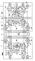
図1による伝送システムは3つの重要な構成要素を有し、これらはTRAU(トランスコーダ及びレートアダプタユニット)2、BTS(基地送受信局)4及び移動局6である。TRAU2は、Aビス(A-bis)インターフェース8を介してBTS4に結合されている。該BTS4は、大気インターフェース10を介して移動ユニット6に結合されている。
【0013】
ここでは移動ユニット6に送信されるべき音声信号である主信号は、音声エンコーダ12に供給される。ソースシンボルとも呼ばれるコード化された音声信号を帯びる該音声エンコーダ12の第1出力端は、上記Aビスインターフェース8を介してチャンネルエンコーダ14に結合されている。背景雑音レベル指示子BDを帯びる音声エンコーダ12の第2出力端は、システムコントローラ16の入力端に結合されている。ここではダウンリンクレート割当信号Rdであるようなコード化特性を伝送する該システムコントローラ16の第1出力端は、音声エンコーダ12に結合されると共に、前記Aビスインターフェースを介して、チャンネルエンコーダ14内のコード化特性設定手段25と、ここではブロックコーダ18である他のチャンネルエンコーダとに結合されている。アップリンクレート割当信号Ruを伝送するシステムコントローラ16の第2出力端は、チャンネルエンコーダ14の第2入力端に結合されている。2ビットのレート割当信号Ruは、2つの連続するフレームにわたり1ビットづつ伝送される。レート割当信号Rd及びRuは、ダウンリンク及びアップリンク伝送系をRd及びRuにより表されるコード化特性で各々動作させるためのリクエストを構成する。
【0014】
移動局6に伝送されるRdの値は、コード化特性系列化手段13により覆すことができることが分かる。このコード化特性系列化手段13は、レート割当信号Ruにより表される所定の系列のコード化特性を、ブロックエンコーダ18、チャンネルエンコーダ14及び音声エンコーダ12に強制することができる。この所定の系列は、伝送フレーム内に追加スペースを要することなく、移動局6に追加情報を伝送するために使用することができる。2以上の所定の系列のコード化特性を使用することが可能である。これら所定の系列のコード化特性の各系列は、別々の補助信号値に対応する。
【0015】
システムコントローラ16は、Aビスインターフェースから、アップリンク及びダウンリンクに関する大気インターフェース10(無線チャンネル)の品質を示す品質尺度Qu及びQd'を受信する。品質尺度Quは複数の閾レベルと比較され、この比較の結果はシステムコントローラ16により、アップリンクの音声エンコーダ36とチャンネルエンコーダ38との間で、利用可能なチャンネル容量を分割するために使用される。信号Qd'はローパスフィルタ22によりフィルタされ、続いて複数の閾値と比較される。該比較の結果は、音声エンコーダ12とチャンネルエンコーダ14との間で利用可能なチャンネル容量を分割するために使用される。アップリンク及びダウンリンクに関しては、音声エンコーダ12とチャンネルエンコーダ14との間のチャンネル容量の4つの異なる分割の組合せが可能である。これらの可能性が下表に示される。
【表1】

【0016】
悪いチャンネル条件の下では、上記チャンネルエンコーダは、所要の伝送品質を得るために、より低いレートを有する必要がある。該チャンネルエンコーダは、8ビットのCRCが付加される音声エンコーダ12の出力ビットをコード化するような、可変レートのたたみ込みエンコーダであろう。該可変レートは、異なる基本レートを有する異なるたたみ込みコードを用いることにより、又は一定の基本レートのたたみ込みコードのパンクチャ処理(puncturing)を用いることにより得ることができる。好ましくは、これらの方法の組合せが使用される。
【0017】
下に示す表2には、表1に示したたたみ込みコードの特性が示されている。これらの全てのたたみ込みコードは5に等しい値νを有している。
【表2】
【数1】
【0018】
異なるコードの各々に関して、当該コードに使用される生成多項式が、対応するセル内の数により示されている。該対応するセル内の数は、ソースシンボルのうちのどれに関して対応する生成多項式が考慮されているかを示す。更に、上記数は、上記多項式を使用することにより導出される、ソースシンボルの系列中におけるコード化されたシンボルの位置を示す。各桁は、指示された生成多項式を用いて導出されたチャンネルシンボルの、チャンネルシンボルの系列中における位置を示す。レート1/2コードに関しては、生成多項式57及び65が使用される。各ソースシンボルに関しては、先ず多項式65により計算されたチャンネルシンボルが送信され、次いで生成多項式57によるチャンネルシンボルが送信される。同様の方法により、レート1/4コードに対するチャンネルシンボルを決定するために使用されるべき多項式は、表2から決定することができる。その他のコードは、パンクチャ処理されたたたみ込みコードである。該表において桁が0に等しい場合は、対応する生成多項式が上記特別のソースシンボルに対しては使用されないことを意味する。表2から、生成多項式の幾つかはソースシンボルの各々に対しては使用されないことが分かる。該テーブルにおける数の系列は、1、3、5又は6より長い入力シンボルの系列に対して各々周期的に継続されることが分かる。
【0019】
表1が、全レートチャンネル及び半レートチャンネルに関して、音声エンコーダ12のビットレート及びチャンネルエンコーダ14のレートの値を示すことが分かる。どのチャンネルが使用されるかについての判断はシステム操作者によりなされ、別の制御チャンネル上で伝送することが可能な帯域外制御信号によりTRAU2、BTS4及び移動局6に通知される。チャンネルエンコーダ14にも、信号Ruが供給される。
【0020】
ブロックコーダ18は、選択されたレートRdを移動局6へ送信すべくコード化するために存在する。このレートRdは、2つの理由により別のエンコーダにおいてコード化される。第1の理由は、上記移動局におけるチャンネルデコーダ28に対し、新たなレートRdによりコード化されたデータが該チャンネルデコーダ28に到達する前に、該新たなレートを通知するのが望ましいということである。第2の理由は、値Rdが、チャンネルエンコーダ14を用いて可能であるよりも、伝送エラーに対して一層良好に保護されるのが望ましいということである。コード化されたRdのエラー訂正特性を、より一層向上させるために、コードワードは別々のフレームで送信される2つの部分に分割される。コードワードの斯かる分割は、より長いコードワードが選択されるのを可能にし、結果としてエラー訂正能力が更に改善される。
【0021】
全レートチャンネルが使用される場合、ブロックコーダ18は2ビットにより表されるコード化特性Rdを、16ビットのコードワードを持つブロックコードによりコード化されるコード化されたコード化特性にコード化する。半レートチャンネルが使用される場合は、8ビットのコードワードを持つブロックコードが、上記コード化特性をコード化するために使用される。使用されるコードワードは下記の表3及び表4に示される。
【表3】
【0022】
チャンネルエンコーダ14及びブロックエンコーダ18の出力は、大気インターフェース10を介して時間分割多重で送信される。しかしながら、幾つかの信号を大気インターフェース10を介して送信するためにCDMAを使用することもできる。移動局6においては、大気インターフェース10から受信された信号は、チャンネルデコーダ28と、ここではブロックデコーダ26である他のチャンネルデコーダとに供給される。ブロックデコーダ26は、前記Rdビットにより表されるコード化特性を、コードワードC0…CNにより表されるコード化されたコード化特性をデコードすることによって導出するように構成されており、ここで、半レートチャンネルに対してはNは7であり、全レートチャンネルに対してはNは15である。
【0023】
ブロックデコーダ26は、4つの可能性のあるコードワードと、その入力信号との間の相関を計算するように構成されている。これは2つの処理でなされる。何故なら、上記コードワードは、2つの連続したフレームで、部分に分けられて送信されるからである。上記コードワードの最初の部分に対応する入力信号が受信された後、可能性のあるコードワードの最初の部分と、入力値との間の相関値が計算され、且つ記憶される。後続のフレームにおいて、上記コードワードの2番目の部分に対応する入力信号が受信されると、可能性のあるコードワードの2番目の部分と該入力信号との間の相関値が計算されて、先に記憶された相関値に加算され、これにより最終的相関値を得る。全入力信号に対して最大の相関値を有するようなコードワードに対応するRdの値が、上記コード化特性を表す受信されたコードワードとして選択され、当該ブロックデコーダ26の出力端に受け渡される。ブロックデコーダ26の出力端は、チャンネルデコーダ28における特性設定手段27の制御入力端と音声デコーダ30の制御入力端とに対し、チャンネルデコーダ28のレート及び音声デコーダ30のビットレートを前記信号Rdに対応する値に設定するために接続されている。
【0024】
チャンネルデコーダ28は該デコーダの入力信号をデコードし、第1出力端において、コード化された音声信号を音声デコーダ30の入力端に供給する。
【0025】
チャンネルデコーダ28は、第2出力端に、フレームの誤った受信を示す信号BFI(不良フレーム指示子)を供給する。このBFI信号は、該チャンネルデコーダ28内のたたみ込みデコーダによりデコードされた信号の一部にわたりチェックサムを計算すると共に、該計算されたチェックサムと大気インターフェース10から受信されたチェックサムの値とを比較することにより得られる。
【0026】
音声デコーダ30は、前記音声エンコーダ12の音声信号の複製を、チャンネルデコーダ28の出力信号から導出するように構成されている。音声デコーダ30は、チャンネルデコーダ28からBFI信号が受信された場合は、先のフレームに対応する先に受信されたパラメータに基づいて音声信号を導出するように構成されている。該音声デコーダ30は、複数の連続するフレームが不良フレームとして示される場合は、該デコーダの出力をミュートするように構成することができる。
【0027】
チャンネルデコーダ28は、第3の出力端にデコードされた信号Ruを供給する。該信号Ruは、ここではアップリンクのビットレート設定であるようなコード化特性を表している。該信号Ruはフレーム当たりに1ビット(RQIビット)を有している。逆フォーマッタ34において、連続するフレームにおいて受信された2つのビットを、2ビットにより表されるアップリンク用のビットレート設定Ru'に合成する。表1に従う、アップリンクに使用されるべき可能性のうちの1つを選択する該ビットレート設定Ru'は、音声エンコーダ36の制御入力端と、チャンネルエンコーダ38の制御入力端と、ここではブロックエンコーダ40であるような他のチャンネルエンコーダの入力端とに供給される。前記チャンネルデコーダ28がBFI信号を送出することにより不良フレームを通知する場合は、デコードされた信号Ruはアップリンクレートを設定するためには使用されない。何故なら、それは信頼性がないと見なされるからである。
【0028】
チャンネルデコーダ28は、更に、第4出力端に品質尺度MMDdを供給する。この尺度MMDは、該チャンネルデコーダでビタビデコーダが使用される場合は、容易に導出することができる。この品質尺度は、処理ユニット32において一次フィルタによりフィルタされる。処理ユニット32における該フィルタの出力信号に関しては:
【数2】
![]()
【0029】
チャンネルデコーダ28のビットレート設定がRdの変化された値に応じて変化された後では、MMD'[n-1]の値は、新たに設定されたビットレート及び典型的なダウンリンクチャンネル品質に対する、上記フィルタされたMMDの長時間平均に対応するような典型的な値に設定される。これは、異なる値のビットレートの間で切り換える場合に、過渡現象を低減するためになされる。
【0030】
上記フィルタの出力信号は、2ビットを用いて品質指示子Qdに量子化される。該品質指示子Qdはチャンネルエンコーダ38の第2入力端に供給される。該2ビットの品質指示子Qdは、2フレーム毎に一度、各フレームの1つのビット位置を用いて伝送される。
【0031】
移動局6における音声エンコーダ36に供給される音声信号は、コード化されてチャンネルエンコーダ38に受け渡される。チャンネルエンコーダ38は該エンコーダの入力ビットにわたりCRC値を計算し、このCRC値を該エンコーダの入力ビットに付加し、該入力ビットとCRC値との合成を、信号Ru'により表1から選択されたたたみ込みコードに従ってコード化する。
【0032】
ブロックエンコーダ40は、2ビットにより表される信号Ru'を、半レートチャンネル又は全レートチャンネルが使用されるかに応じて表3又は表4に従いコード化する。ここでも、コードワードの半分のみが1つのフレーム内で送信される。
【0033】
移動局6内のチャンネルエンコーダ38及びブロックエンコーダ40の出力信号は、大気インターフェース10を介してBTS4に送信される。該BTS4においては、上記のブロックコード化された信号Ru'は、ここではブロックデコーダ42であるような他のチャンネルデコーダによりデコードされる。該ブロックデコーダ42の動作は、前記ブロックデコーダ26の動作と同一である。ブロックデコーダ42の出力端には、信号Ru"により表されるデコードされたコード化特性が得られる。このデコードされた信号Ru"は、チャンネルデコーダ44内のコード化特性設定手段43の制御入力端に供給され、Aビスインターフェースを介して音声デコーダ48の制御入力端に受け渡される。
【0034】
BTS4においては、大気インターフェース10を介して受信されたチャンネルエンコーダ38からの信号は、チャンネルデコーダ44に供給される。チャンネルデコーダ44は、該デコーダの入力信号をデコードし、該デコードされた信号をAビスインターフェース8を介してTRAU2に受け渡す。チャンネルデコーダ44は、アップリンクの伝送品質を表す品質尺度MMDuを処理ユニット46に供給する。該処理ユニット46は、前記処理ユニット32及び22において実行されるものと同様のフィルタ処理を実行する。次いで、該フィルタ処理の結果は、2ビットに量子化され、Aビスインターフェース8を介してTRAU2に送信される。
【0035】
システムコントローラ16においては、判定ユニット20が、アップリンクに使用されるべきビットレート設定Ruを上記品質尺度Quから決定する。通常の環境下では、音声エンコーダに割り当てられるチャンネル容量の部分は、チャンネル品質の増加に伴い増加するであろう。レートRuは2フレーム毎に一度送信される。
【0036】
チャンネルデコーダ44から受信された信号Qd'は、システムコントローラ16内の処理ユニット22に受け渡される。該処理ユニット22においては、2つの連続するフレームで受信されるQd'を表すビットが組み立てられ、該信号Qd'は前記処理ユニット32内のローパスフィルタと同様の特性を持つ一次ローパスフィルタによりフィルタされる。
【0037】
該フィルタされた信号Qd'は、ダウンリンクレートRdの実際の値に依存する2つの閾値と比較される。該フィルタされた信号Qd'が上記閾値の最低のものより低い場合は、当該信号品質はレートRdに対しては低過ぎ、該処理ユニットは現在のレートよりも1段低いレートに切り換える。上記のフィルタされた信号Qd'が上記閾値の最高のものを越える場合は、当該信号品質はレートRdにとっては高過ぎるので、該処理ユニットは現在のレートよりも1段高いレートに切り換える。アップリンクレートRuに関して採る判定も、上記ダウンリンクレートRdに関して採る判定と同様である。
【0038】
ここでも、通常の環境下では、音声エンコーダに割り当てられるチャンネル容量の部分は、チャンネル品質の増加に伴い増加するであろう。特別な環境下では、信号Rdは移動局に対して再構成信号を送信するために使用することもできる。この再構成信号は、例えば、別の音声コード化/デコード及び/又はチャンネルコード化/デコードアルゴリズムが使用されるべきであることを示すことができる。この再構成信号は、Rd信号の特別な所定の系列(シーケンス)を用いてコード化することができる。Rd信号の該特別な所定の系列は、移動局内のエスケープ系列デコーダ31により認識される。該デコーダは所定の(エスケープ)系列が検出された場合に、有効化された装置に再構成信号を発するように構成されている。該エスケープ系列デコーダ31は、Rdの連続する値がクロックされるシフトレジスタを有することができる。該シフトレジスタの内容を上記所定の系列と比較することにより、何時エスケープ系列が受信されたか、及び可能性のあるエスケープ系列のどれが受信されたかを容易に検出することができる。
【0039】
コード化された音声信号を表すチャンネルデコーダ44の出力信号は、Aビスインターフェースを介してTRAU2に送信される。該TRAU2においては、上記コード化された音声信号は音声デコーダ48に供給される。チャンネルデコーダ44の出力端における、CRCエラーの検出を示す信号BFIは、Aビスインターフェース8を介して音声デコーダ48に受け渡される。音声デコーダ48は、前記音声エンコーダ36の音声信号の複製を、チャンネルデコーダ44の出力信号から導出するように構成されている。該音声デコーダ48は、チャンネルデコーダ44からBFI信号が受信された場合は、前記音声デコーダ30において実行されたのと同様に、先のフレームに対応する先に受信された信号に基づいて音声信号を導出するように構成されている。該音声デコーダ48は、複数の連続するフレームが不良フレームとして示される場合は、より進んだエラー隠蔽処理を実行するように構成することができる。
【0040】
図2は、本発明による伝送システムにおいて使用されるフレームフォーマットを示している。音声エンコーダ12又は36は、伝送エラーに対して保護されるべきCビットの群60と、伝送エラーに対して保護する必要のないUビットの群64とを供給する。前記他の系列が該Uビットを有する。判定ユニット20及び処理ユニット32は、前述したような通知の目的で、フレーム毎に1ビットのRQI62を供給する。
【0041】
ビットの上記組合せはチャンネルエンコーダ14又は38に供給され、該エンコーダは先ず上記RQIビットとCビットとの組合せにわたってCRCを算出し、8つのCRCビットをCビット60及びRQIビット62の後に付加する。前記Uビットは上記CRCビットの算出には関与されない。Cビット60とRQIビット62との組合せ66及びCRCビット68は、たたみ込みコードに従ってコード化された系列70にコード化される。前記コード化されたシンボルは、該コード化された系列70を構成する。上記Uビットは変化されないままである。
【0042】
上記組合せ66のビット数は、下記の表5に示されるように、当該たたみ込みエンコーダのレートと、使用されるチャンネルの型式とに依存する。
【表5】
【図面の簡単な説明】
【図1】 図1は、本発明による伝送システムを示す。
【図2】 図2は、図1に従う伝送システムに使用されるフレーム構造を示す。
【符号の説明】
2 トランスコーダ及びレートアダプタユニット
4 基地送受信局
6 移動局
8 Aビスインターフェース
10 大気インターフェース
12 音声エンコーダ
13 コード化特性系列化手段
14 チャンネルエンコーダ
16 システムコントローラ
18 ブロックエンコーダ
20 判定ユニット
22 処理ユニット
25 コード化特性設定手段
26 ブロックデコーダ
28 チャンネルデコーダ
30 音声デコーダ
31 エスケープ系列デコーダ
32 処理ユニット
36 音声エンコーダ
38 チャンネルエンコーダ
40 ブロックエンコーダ
42 ブロックデコーダ
43 コード化特性設定手段
44 チャンネルデコーダ
46 処理ユニット
48 音声デコーダ
60 Cビットの群
62 RQIビット
64 Uビットの群
66 たたみ込みコードに従ってコード化された系列
68 CRCビット【Technical field】
[0001]
The present invention is a transmission system having a transmitter coupled to a receiver via a transmission channel, wherein the transmitter is configured to transmit a main signal and an auxiliary signal to the receiver, the reception The machine relates to a transmission system configured to receive a main signal and an auxiliary signal.
[0002]
The invention also relates to a transmitter and a receiver for use in the transmission system. The invention further relates to a transmission method and a signal.
[0003]
[Background]
In transmission systems it is often desirable to transmit an auxiliary signal in addition to the main signal. The main signal is, for example, a voice (speech) signal transmitted via a radio link of a mobile telephone system. Auxiliary signals, for example, to adapt to signal changes that the receiver must receive,It is a control signal for requesting reconfiguration of the receiver.
[0004]
It is possible to include a special field in the transmission frame for such an auxiliary signal, but if the auxiliary signal is rarely used, a special field is included in the transmission frame as described above. Inclusion is very inefficient. It is also possible to use a frame structure that is changed when the auxiliary signal is to be transmitted. The use of various frame structures will significantly increase the complexity of the transmission system.
[0005]
DISCLOSURE OF THE INVENTION
The object of the present invention is a transmission system having a transmitter coupled to a receiver via a transmission channel, which can avoid the inefficiency and added complexity described above, the transmitter comprising a main signal and an auxiliary signal Is transmitted to a receiver, the receiver providing a transmission system configured to receive a main signal and an auxiliary signal.
[0006]
To achieve this object, the transmission system according to the invention comprises an encoder for encoding the main signal in a manner in which the transmitter is described by coding characteristics, and the receiver is described by coding characteristics. A predetermined sequence in which the transmitter depends on the auxiliary signal, with a decoder for decoding the main signal in the manner(sequence)Encoding means for changing the coding characteristics according to the coding characteristics, and the receiver has the coding characteristicsofA sequence detector for detecting the predetermined sequence is provided.
[0007]
The transmission system according to the invention takes advantage of the fact that the main signal is often coded. In general, the main signal source code to reduce its bit rateMethodAnd / or channel codes that enable reliable transmission of the main signal over the transmission channelMethodCoded according to Source codeMethodCan include the use of CELP encoding for audio signals, source codeConversionCan include the use of error correction codes such as convolutional encoders or Reed-Solomon block codes. The coding characteristics are the output bit rate of the speech encoder,Or at the rate of the convolutional encoderpossible. In some transmission systems, the code characteristics are changed on the fly in response to changes in transmission channel capacity. This transmission channel capacity varies due to reduced or increased signal strength and / or interference received from the radio link, or more or less congestion of a transmission network such as the Internet.
[0008]
Depending on the purposeIn a given seriesThereforeBy changing the coding characteristics, it is possible to send the auxiliary signal to the receiver without reserving extra space in the frame structure or without having to use a variable frame structure.
[0009]
Of the present inventionOneIn the embodiment, the transmission system is,The transmission quality of the transmission channelspecificTransmission quality forspecificDepending on the means and transmission quality said coding characteristicsTheAdaptive means for adapting, wherein the coding characteristic sequencing means,Transmission qualityspecificBy meansIdentifiedValue corresponding to transmission quality lower than the transmission qualityOnlyConfigured to change encoding characteristicsthingIt is characterized by.
[0010]
thisAccording to the strategy, Thanks to the action of the coding property series means,no longerPreventing reliable transmission from being performedSelection of appropriate coding characteristicsTo prevent that.this problemOccurs when the coding characteristic sequencing means switches to a coding characteristic that only applies to transmission quality better than the current transmission quality.Can.
[0011]
BEST MODE FOR CARRYING OUT THE INVENTION
Hereinafter, the present invention will be described with reference to the accompanying drawings.
[0012]
The transmission system according to FIG. 1 has three important components: TRAU (transcoder and rate adapter unit) 2, BTS (base transceiver station) 4 and mobile station 6. The TRAU 2 is coupled to the BTS 4 via an A-bis interface 8. The BTS 4 is coupled to the mobile unit 6 via the atmospheric interface 10.
[0013]
Here, a main signal which is an audio signal to be transmitted to the mobile unit 6 is supplied to the
[0014]
R transmitted to mobile station 6dThe value ofIt can be seen that this can be overridden by the coded characteristic series grouping means 13. This coding characteristic series grouping means 13Rate assignment signal RuThe coding characteristics of a given sequence represented by,
[0015]
The system controller 16,From the A-bis interface,Quality measure Q indicating the quality of the air interface 10 (radio channel) for the uplink and downlinkuAnd Qd'Receive. Quality scale QuAre compared to a plurality of threshold levels, and the result of this comparison is transmitted by system controller 16 between
[Table 1]
[0016]
Under bad channel conditions, the channel encoder needs to have a lower rate in order to obtain the required transmission quality. The channel encoder encodes the output bits of the
[0017]
Table 2 below shows the characteristics of the convolutional code shown in Table 1. All these convolutional codes have a value ν equal to 5.
[Table 2]
[Expression 1]
[0018]
For each different code, the generator polynomial used for that code is indicated by the number in the corresponding cell. The number in the corresponding cell indicates for which of the source symbols the corresponding generator polynomial is considered. Furthermore, the number is derived by using the polynomial.,Source symbol seriesDuring ~InOf coded symbolsIndicates the position. Each digit is a channel symbol sequence of channel symbols derived using the indicated generator polynomialDuring ~Indicates the position. For rate 1/2 codes, generator polynomials 57 and 65 are used. For each source symbol, first the channel symbol calculated by the polynomial 65 is transmitted, and then the channel symbol by the generator polynomial 57 is transmitted. In a similar manner, the polynomial to be used to determine the channel symbol for the rate 1/4 code can be determined from Table 2. The other codes are punctured convolution codes. A digit equal to 0 in the table means that the corresponding generator polynomial is not used for the special source symbol. From Table 2, it can be seen that some of the generator polynomials are not used for each of the source symbols. It can be seen that the series of numbers in the table each continues periodically for a series of input symbols longer than 1, 3, 5 or 6.
[0019]
Table 1 is,For full rate and half rate channels,It can be seen that the bit rate of the
[0020]
A
[0021]
If the full-rate channel is used, the
[Table 3]
[0022]
The outputs of the
[0023]
Block decoder 26 is configured to calculate the correlation between the four possible codewords and their input signals. This is done in two processes. Because the codeword above is,2 consecutive framesso,portionDivided intoIt is because it is transmitted. After an input signal corresponding to the first part of the codeword is received, the first part of the possible codeword and,The correlation value between the input values is calculated,And memorized. In a subsequent frame, an input signal corresponding to the second part of the codeword is receivedWhenThe correlation value between the second part of the possible codeword and the input signal is calculated and added to the previously stored correlation value, thereby obtaining the final correlation value. R corresponding to a codeword having the maximum correlation value for all input signalsdIs selected as the received codeword representing the coding characteristic and is passed to the output of the block decoder 26. The output terminal of the block decoder 26 has the signal R for the rate of the
[0024]
The
[0025]
The
[0026]
The audio decoder 30 reproduces the audio signal of the audio encoder 12.,It is configured to derive from the output signal of the
[0027]
The
[0028]
The
[Expression 2]
![]()
[0029]
The bit rate setting of the
[0030]
The output signal of the filter is a quality indicator Q using 2 bits.dQuantized to The quality indicator QdIs supplied to the second input end of the
[0031]
The audio signal supplied to the
[0032]
The block encoder 40 is a signal R represented by 2 bits.u'Is coded according to Table 3 or Table 4 depending on whether half-rate channel or full-rate channel is used. Again, only half of the codeword is transmitted in one frame.
[0033]
Output signals from the
[0034]
In the BTS 4, the signal from the
[0035]
In the system controller 16, the
[0036]
Signal Q received from channel decoder 44d'Is passed to the
[0037]
The filtered signal Qd'Is the downlink rate RdTo two thresholds depending on the actual value of. The filtered signal QdIf 'is lower than the lowest threshold, the signal quality is rate RdIs too low, the processing unit switches to a rate one step lower than the current rate. The above filtered signal QdIf 'exceeds the highest threshold, the signal quality is rate RdIs too high for the processing unit, the processing unit switches to a rate one step higher than the current rate. Uplink rate RuThe determination to be taken with respect to the downlink rate RdIt is the same as the determination taken for.
[0038]
Again, under normal circumstances, the portion of the channel capacity allocated to the speech encoder will increase with increasing channel quality. Under special circumstances, the signal RdCan also be used to send a reconfiguration signal to the mobile station. This reconstructed signal can indicate, for example, that another audio encoding / decoding and / or channel encoding / decoding algorithm should be used. This reconstruction signal is RdSpecial predetermined series of signals(sequence)Can be coded using RdThe special predetermined sequence of signals is recognized by an
[0039]
The output signal of the channel decoder 44 representing the encoded audio signal is transmitted to the TRAU 2 via the A-bis interface. In the TRAU 2, the coded audio signal is supplied to the
[0040]
FIG. 2 shows the frame format used in the transmission system according to the invention. The
[0041]
The combination of bits is supplied to the
[0042]
The number of bits of the
[Table 5]
[Brief description of the drawings]
FIG. 1 shows a transmission system according to the invention.
FIG. 2 showsAccording to FIG.2 shows a frame structure used in a transmission system.
[Explanation of symbols]
2 Transcoder and rate adapter unit
4 base transceiver stations
6 Mobile stations
8 A screw interface
10 Atmospheric interface
12 Speech encoder
13 Coded characteristics series means
14 channel encoder
16 System controller
18 block encoder
20 judgment unit
22 Processing unit
25 Coding characteristic setting means
26 block decoder
28 channel decoder
30 audio decoder
31 Escape series decoder
32 processing units
36 Speech encoder
38 channel encoder
40 block encoder
42 block decoder
43 Coding characteristic setting means
44 channel decoder
46 processing unit
48 audio decoder
60 C-bit group
62 RQI bit
64 U-bit group
66 Sequence coded according to convolutional code
68 CRC bits
Claims (7)
前記送信機が、
コード化特性により記述されるやり方で主信号をコード化するためのエンコーダと、
補助信号を前記受信機に伝送するため、該補助信号に依存する所定の系列に従って、前記コード化特性を変更するためのコード化特性系列化手段と、
前記主信号および前記コード化特性を、前記受信機に送信する送信手段とを有し、
前記受信機が、
前記主信号および前記コード化特性を、前記送信機から受信する受信手段と、
前記コード化特性により記述されるやり方で前記主信号をデコードするためのデコーダと、
前記コード化特性の前記所定の系列を検出することにより、前記送信機から前記補助信号を受け取るための系列検出手段とを有することを特徴とする伝送システム。 A transmission system for transmitting a signal from a transmitter to a receiver via a transmission channel ,
Said transmitter,
An encoder for encoding the main signal in a manner described by the encoding characteristics ;
Coding characteristic sequencer for changing the coding characteristic according to a predetermined sequence depending on the auxiliary signal for transmitting an auxiliary signal to the receiver;
Transmission means for transmitting the main signal and the coding characteristic to the receiver;
The receiver,
Receiving means for receiving the main signal and the coding characteristic from the transmitter;
A decoder for decoding the main signal in a manner described by the coding characteristics ;
A transmission system comprising: sequence detection means for receiving the auxiliary signal from the transmitter by detecting the predetermined sequence of the coding characteristics.
補助信号を受信機に伝送するため、該補助信号に依存する所定の系列に従って、前記コード化特性を変更するためのコード化特性系列化手段と、
前記主信号および前記コード化特性を、前記受信機に送信する送信手段とを有することを特徴とする送信機。 An encoder for encoding the main signal in a manner described by the encoding characteristics;
Coding characteristic sequencer for changing the coding characteristic according to a predetermined sequence depending on the auxiliary signal for transmitting the auxiliary signal to the receiver;
Transmitter having transmitting means for transmitting the main signal and the coding characteristic to the receiver .
前記コード化特性により記述されるやり方で前記主信号をデコードするためのデコーダと、A decoder for decoding the main signal in a manner described by the coding characteristics;
前記コード化特性の所定の系列を検出することにより、前記送信機から補助信号を受け取るための系列検出手段とを有することを特徴とする受信機。A receiver comprising: a sequence detection means for receiving an auxiliary signal from the transmitter by detecting a predetermined sequence of the coding characteristics.
送信側において、コード化特性により記述されるやり方で主信号をコード化するステップと、
送信側において、補助信号を受信側に伝送するため、該補助信号に依存する所定の系列に従って、前記コード化特性を変更するステップと、
前記主信号および前記コード化特性を、送信側から受信側に送信するステップと、
受信側において、前記コード化特性により記述されるやり方で前記主信号をデコードするステップと、
受信側において、前記コード化特性の前記所定の系列を検出することにより、前記補助信号を受け取るステップとを有することを特徴とする方法。 In a method for transmitting and receiving signals ,
At the transmitting side, encoding the main signal in a manner described by the encoding characteristics ;
On the transmitting side, to transmit the auxiliary signal to the receiving side, changing the coding characteristic according to a predetermined sequence depending on the auxiliary signal;
Transmitting the main signal and the coding characteristic from a transmitting side to a receiving side;
Decoding at the receiver side the main signal in a manner described by the coding characteristics ;
Receiving at the receiving side the auxiliary signal by detecting the predetermined sequence of the coding characteristics.
コード化特性により記述されるやり方で主信号をコード化するステップと、
補助信号を受信側に伝送するため、該補助信号に依存する所定の系列に従って、前記コード化特性を変更するステップと、
前記主信号および前記コード化特性を、送信するステップとを有することを特徴とする方法。 In a method for transmitting a signal ,
Encoding the main signal in a manner described by the encoding characteristics ;
Changing the coding characteristics in accordance with a predetermined sequence depending on the auxiliary signal to transmit the auxiliary signal to the receiving side;
Transmitting the main signal and the coding characteristic .
主信号およびコード化特性を受信するステップと、
前記コード化特性により記述されるやり方で前記主信号をデコードするステップと、
前記コード化特性の所定の系列を検出することにより、補助信号を受け取るステップとを有することを特徴とする方法。 In a method for receiving a signal ,
Receiving a main signal and coding characteristics;
Decoding the main signal in a manner described by the coding characteristics;
Receiving an auxiliary signal by detecting a predetermined sequence of the coding characteristics .
Applications Claiming Priority (3)
| Application Number | Priority Date | Filing Date | Title |
|---|---|---|---|
| EP98201733 | 1998-05-26 | ||
| EP98201733.7 | 1998-05-26 | ||
| PCT/IB1999/000919 WO1999062212A2 (en) | 1998-05-26 | 1999-05-20 | Transmission system for transmitting a main signal and an auxiliary signal |
Publications (3)
| Publication Number | Publication Date |
|---|---|
| JP2002517130A JP2002517130A (en) | 2002-06-11 |
| JP2002517130A5 JP2002517130A5 (en) | 2009-01-15 |
| JP4361691B2 true JP4361691B2 (en) | 2009-11-11 |
Family
ID=8233758
Family Applications (1)
| Application Number | Title | Priority Date | Filing Date |
|---|---|---|---|
| JP2000551510A Expired - Lifetime JP4361691B2 (en) | 1998-05-26 | 1999-05-20 | Transmission system for transmitting main and auxiliary signals |
Country Status (8)
| Country | Link |
|---|---|
| US (3) | US6574247B1 (en) |
| EP (1) | EP1000479B1 (en) |
| JP (1) | JP4361691B2 (en) |
| KR (1) | KR100621165B1 (en) |
| CN (1) | CN1272271B (en) |
| DE (1) | DE69936702T2 (en) |
| TW (1) | TW376497B (en) |
| WO (1) | WO1999062212A2 (en) |
Families Citing this family (22)
| Publication number | Priority date | Publication date | Assignee | Title |
|---|---|---|---|---|
| US3019128A (en) * | 1957-09-17 | 1962-01-30 | Union Carbide Corp | Coated carbonaceous articles |
| US7058086B2 (en) * | 1999-05-26 | 2006-06-06 | Xm Satellite Radio Inc. | Method and apparatus for concatenated convolutional encoding and interleaving |
| EP1187385A1 (en) * | 2000-09-12 | 2002-03-13 | Lucent Technologies Inc. | Signalling of data rate and diversity configuration |
| US20030117437A1 (en) * | 2001-10-24 | 2003-06-26 | Cook Thomas A. | Portal administration tool |
| US7898972B2 (en) * | 2002-01-17 | 2011-03-01 | Agere Systems Inc. | Auxiliary coding for home networking communication system |
| US8179864B2 (en) | 2002-08-06 | 2012-05-15 | Rockstar Bidco Lp | Method of controlling a communications link |
| US7957263B2 (en) * | 2003-09-08 | 2011-06-07 | Qualcomm Corporation | Method and apparatus for acknowledging reverse link transmissions in a communications system |
| US7991056B2 (en) * | 2004-02-13 | 2011-08-02 | Broadcom Corporation | Method and system for encoding a signal for wireless communications |
| US8102878B2 (en) | 2005-09-29 | 2012-01-24 | Qualcomm Incorporated | Video packet shaping for video telephony |
| US8406309B2 (en) | 2005-10-21 | 2013-03-26 | Qualcomm Incorporated | Video rate adaptation to reverse link conditions |
| US8842555B2 (en) * | 2005-10-21 | 2014-09-23 | Qualcomm Incorporated | Methods and systems for adaptive encoding of real-time information in packet-switched wireless communication systems |
| US8514711B2 (en) | 2005-10-21 | 2013-08-20 | Qualcomm Incorporated | Reverse link lower layer assisted video error control |
| US8548048B2 (en) | 2005-10-27 | 2013-10-01 | Qualcomm Incorporated | Video source rate control for video telephony |
| US8036242B2 (en) * | 2006-02-15 | 2011-10-11 | Qualcomm Incorporated | Dynamic capacity operating point management for a vocoder in an access terminal |
| US7778226B2 (en) * | 2006-03-30 | 2010-08-17 | Intel Corporation | Device, system and method of coordination among multiple transceivers |
| EP2109982B1 (en) | 2007-01-10 | 2018-08-08 | Qualcomm Incorporated | Content- and link-dependent coding adaptation for multimedia telephony |
| US8797850B2 (en) | 2008-01-10 | 2014-08-05 | Qualcomm Incorporated | System and method to adapt to network congestion |
| US7907070B2 (en) * | 2008-09-12 | 2011-03-15 | Sharp Laboratories Of America, Inc. | Systems and methods for providing unequal error protection using embedded coding |
| US8724727B2 (en) * | 2009-05-06 | 2014-05-13 | Futurewei Technologies, Inc. | System and method for outer loop link adaptation for a wireless communications system |
| US10298736B2 (en) * | 2015-07-10 | 2019-05-21 | Electronics And Telecommunications Research Institute | Apparatus and method for processing voice signal and terminal |
| JP6508347B2 (en) * | 2015-09-17 | 2019-05-08 | 日本電気株式会社 | Terminal apparatus, control method therefor, and control program for terminal apparatus |
| CN113219941B (en) * | 2021-04-22 | 2022-09-20 | 湖南联塑科技实业有限公司 | Signal linking and confirming method between industrial equipment |
Family Cites Families (12)
| Publication number | Priority date | Publication date | Assignee | Title |
|---|---|---|---|---|
| US3909721A (en) * | 1972-01-31 | 1975-09-30 | Signatron | Signal processing system |
| US4047151A (en) * | 1974-12-24 | 1977-09-06 | Rydbeck Nils R C | Adaptive error correcting transmission system |
| JP2892206B2 (en) * | 1991-12-24 | 1999-05-17 | 松下電器産業株式会社 | Audio data transmission device |
| CA2131674A1 (en) * | 1993-09-10 | 1995-03-11 | Kalyan Ganesan | High performance error control coding in channel encoders and decoders |
| FR2718906B1 (en) * | 1994-04-13 | 1996-05-24 | Alcatel Mobile Comm France | Method for adapting the air interface in a radiocommunication system with mobiles, base station, mobile station and corresponding transmission mode. |
| US5768296A (en) * | 1994-07-01 | 1998-06-16 | Quantum Corporation | ECC system supporting different-length Reed-Solomon codes whose generator polynomials have common roots |
| US6292476B1 (en) * | 1997-04-16 | 2001-09-18 | Qualcomm Inc. | Method and apparatus for providing variable rate data in a communications system using non-orthogonal overflow channels |
| US5671225A (en) * | 1995-09-01 | 1997-09-23 | Digital Equipment Corporation | Distributed interactive multimedia service system |
| US5722051A (en) * | 1996-02-13 | 1998-02-24 | Lucent Technologies Inc. | Adaptive power control and coding scheme for mobile radio systems |
| JPH09224018A (en) * | 1996-02-16 | 1997-08-26 | Nippon Telegr & Teleph Corp <Ntt> | Automatic retransmission method and transmitter and receiver for the method |
| US5671255A (en) * | 1996-03-29 | 1997-09-23 | Motorola, Inc. | Method and apparatus for determining coding rate in a wireless communication system |
| SE9601606D0 (en) * | 1996-04-26 | 1996-04-26 | Ericsson Telefon Ab L M | Ways for radio telecommunication systems |
-
1998
- 1998-05-29 TW TW087108465A patent/TW376497B/en not_active IP Right Cessation
-
1999
- 1999-05-20 WO PCT/IB1999/000919 patent/WO1999062212A2/en active IP Right Grant
- 1999-05-20 CN CN99800839.7A patent/CN1272271B/en not_active Expired - Lifetime
- 1999-05-20 JP JP2000551510A patent/JP4361691B2/en not_active Expired - Lifetime
- 1999-05-20 EP EP99918239A patent/EP1000479B1/en not_active Expired - Lifetime
- 1999-05-20 KR KR1020007000758A patent/KR100621165B1/en not_active IP Right Cessation
- 1999-05-20 DE DE69936702T patent/DE69936702T2/en not_active Expired - Lifetime
- 1999-05-24 US US09/316,994 patent/US6574247B1/en not_active Expired - Lifetime
-
2003
- 2003-04-08 US US10/409,438 patent/US7154917B2/en not_active Expired - Lifetime
-
2006
- 2006-09-27 US US11/535,639 patent/US7756166B2/en not_active Expired - Fee Related
Also Published As
| Publication number | Publication date |
|---|---|
| WO1999062212A3 (en) | 2000-02-03 |
| US7756166B2 (en) | 2010-07-13 |
| JP2002517130A (en) | 2002-06-11 |
| EP1000479A2 (en) | 2000-05-17 |
| TW376497B (en) | 1999-12-11 |
| US20030193971A1 (en) | 2003-10-16 |
| DE69936702T2 (en) | 2008-04-30 |
| CN1272271A (en) | 2000-11-01 |
| CN1272271B (en) | 2014-10-15 |
| KR100621165B1 (en) | 2006-09-13 |
| DE69936702D1 (en) | 2007-09-13 |
| EP1000479B1 (en) | 2007-08-01 |
| KR20010022186A (en) | 2001-03-15 |
| US6574247B1 (en) | 2003-06-03 |
| US7154917B2 (en) | 2006-12-26 |
| WO1999062212A2 (en) | 1999-12-02 |
| US20070286239A1 (en) | 2007-12-13 |
Similar Documents
| Publication | Publication Date | Title |
|---|---|---|
| US7756166B2 (en) | Transmission system for transmitting a main signal and an auxiliary signal | |
| JP5150739B2 (en) | Transmission system with adaptive channel encoder and decoder | |
| JP2002517130A5 (en) | ||
| KR100713677B1 (en) | Speech decoder, speech decoding method, and transmission system including the speech decoder | |
| US6421527B1 (en) | System for dynamic adaptation of data/channel coding in wireless communications | |
| KR100413097B1 (en) | Data transmission method, data transmission system, transmitter and receiver | |
| AU739176B2 (en) | An information coding method and devices utilizing error correction and error detection | |
| EP1000480B1 (en) | Transmission system with adaptive channel encoder and decoder | |
| WO2000013448A2 (en) | A method, communication system, mobile station and network element for transmitting background noise information in data transmission in data frames | |
| US6304612B1 (en) | Transmission system having a simplified channel decoder |
Legal Events
| Date | Code | Title | Description |
|---|---|---|---|
| A521 | Written amendment |
Free format text: JAPANESE INTERMEDIATE CODE: A523 Effective date: 20060519 |
|
| A621 | Written request for application examination |
Free format text: JAPANESE INTERMEDIATE CODE: A621 Effective date: 20060519 |
|
| A131 | Notification of reasons for refusal |
Free format text: JAPANESE INTERMEDIATE CODE: A131 Effective date: 20080819 |
|
| A524 | Written submission of copy of amendment under section 19 (pct) |
Free format text: JAPANESE INTERMEDIATE CODE: A524 Effective date: 20081118 |
|
| A131 | Notification of reasons for refusal |
Free format text: JAPANESE INTERMEDIATE CODE: A131 Effective date: 20090319 |
|
| TRDD | Decision of grant or rejection written | ||
| A01 | Written decision to grant a patent or to grant a registration (utility model) |
Free format text: JAPANESE INTERMEDIATE CODE: A01 Effective date: 20090716 |
|
| A01 | Written decision to grant a patent or to grant a registration (utility model) |
Free format text: JAPANESE INTERMEDIATE CODE: A01 |
|
| A61 | First payment of annual fees (during grant procedure) |
Free format text: JAPANESE INTERMEDIATE CODE: A61 Effective date: 20090813 |
|
| R150 | Certificate of patent or registration of utility model |
Free format text: JAPANESE INTERMEDIATE CODE: R150 |
|
| FPAY | Renewal fee payment (event date is renewal date of database) |
Free format text: PAYMENT UNTIL: 20120821 Year of fee payment: 3 |
|
| FPAY | Renewal fee payment (event date is renewal date of database) |
Free format text: PAYMENT UNTIL: 20130821 Year of fee payment: 4 |
|
| R250 | Receipt of annual fees |
Free format text: JAPANESE INTERMEDIATE CODE: R250 |
|
| R250 | Receipt of annual fees |
Free format text: JAPANESE INTERMEDIATE CODE: R250 |
|
| R250 | Receipt of annual fees |
Free format text: JAPANESE INTERMEDIATE CODE: R250 |
|
| R250 | Receipt of annual fees |
Free format text: JAPANESE INTERMEDIATE CODE: R250 |
|
| R250 | Receipt of annual fees |
Free format text: JAPANESE INTERMEDIATE CODE: R250 |
|
| R250 | Receipt of annual fees |
Free format text: JAPANESE INTERMEDIATE CODE: R250 |
|
| EXPY | Cancellation because of completion of term |