JP4360526B2 - Hologram observation tool and computer generated hologram therefor - Google Patents
Hologram observation tool and computer generated hologram therefor Download PDFInfo
- Publication number
- JP4360526B2 JP4360526B2 JP2003205316A JP2003205316A JP4360526B2 JP 4360526 B2 JP4360526 B2 JP 4360526B2 JP 2003205316 A JP2003205316 A JP 2003205316A JP 2003205316 A JP2003205316 A JP 2003205316A JP 4360526 B2 JP4360526 B2 JP 4360526B2
- Authority
- JP
- Japan
- Prior art keywords
- hologram
- computer generated
- generated hologram
- reproduced
- pattern
- Prior art date
- Legal status (The legal status is an assumption and is not a legal conclusion. Google has not performed a legal analysis and makes no representation as to the accuracy of the status listed.)
- Expired - Lifetime
Links
Images


Classifications
-
- G—PHYSICS
- G03—PHOTOGRAPHY; CINEMATOGRAPHY; ANALOGOUS TECHNIQUES USING WAVES OTHER THAN OPTICAL WAVES; ELECTROGRAPHY; HOLOGRAPHY
- G03H—HOLOGRAPHIC PROCESSES OR APPARATUS
- G03H2270/00—Substrate bearing the hologram
- G03H2270/55—Substrate bearing the hologram being an optical element, e.g. spectacles
Landscapes
- Holo Graphy (AREA)
Description
【0001】
【発明の属する技術分野】
本発明は、ホログラム観察具とそのための計算機ホログラムに関し、特に、作りやすく、ホログラムメガネを通して見える画像が安定して明るいホログラムメガネとそのための計算機ホログラムに関するものである。
【0002】
【従来の技術】
特許文献1においてホログラムメガネが提案されている。このホログラムメガネは、図7(a)に斜視図を示すような構成になっている。すなわち、メガネフレーム1の両眼用の枠内には、2つの透過型ホログラム2、3が嵌め込まれている。この透過型ホログラム2、3を用いたメガネを掛けて図7(b)に示すような小面積の光源4、5、6、7を含むシーンを見ると、例えば図7(c)に示すように見える。すなわち、図7(b)の実際のシーンにおける光源4、5、6、7がそれぞれ予め選択されたパターン「NOEL」8、9、10、11に置き替わったシーンとして見える。このような特性を持つ透過型ホログラム2、3としては、計算機ホログラムとして構成された上記パターン「NOEL」のフーリエ変換ホログラム(フラウンホーファーホログラム)が用いられる。
【特許文献1】
米国特許第5,546,198号明細書
【非特許文献1】
日本光学会(応用物理学会)主催 第22回冬期講習会テキスト「ホログラムと回折型光学素子−基礎理論から産業応用まで−」pp.36〜39
【0003】
【発明が解決しようとする課題】
計算機によって得られるフーリエ変換ホログラムは、そのホログラムに記録されるパターン(上記の例では、「NOEL」)を含む制限された矩形領域を縦横に碁盤目状のセルに区切って、セル位置に対応するパターン部分の情報を各セルに持たせ、その限られた数のセルからなるパターンを遠方のホログラム領域にフーリエ変換して投影して構成されているもので、実際には、ホログラム領域も記録するパターン領域と同様に縦横に碁盤目状のセルに区切って、記録するパターンのフーリエ変換された各セル位置の振幅情報と位相情報を記録してなるものである。
【0004】
このように、予め選択されたパターンを記録したフーリエ変換計算機ホログラムは、有限の数のセルからなるものであるため、回折効率が必ずしも高くなく、上記のホログラムメガネを通して見えるパターンは必ずしも明るいものではなく、また、そのパターンに共役像が重なって見え、さらには、主たるパターンの周囲に近接して高次回折像が見えてしまい、見やすく十分な特性のものと言うことはできなかった。
【0005】
また、このような計算機ホログラムの作製には、高速フーリエ変換によって作製されたマスクを使用するフォトリソグラフィーの技術が用いられるが、マスクの描画パターンが非常に微細であるため、安定的に所定のパターンを再生する計算機ホログラムを作製することは容易ではない。
【0006】
本発明は従来技術のこのような問題点に鑑みてなされたものであり、その目的は、高回折効率で明るいパターンがシーン中の光源に置き替わって見え、共役像、高次像が出ても気にならず、かつ、所定の特性のものの作製が容易なホログラム観察具とそのための計算機ホログラムを提供することである。
【0007】
【課題を解決するための手段】
上記目的を達成する本発明のホログラム観察具は、透過型のフーリエ変換ホログラムとして構成され計算機ホログラムからなるホログラム観察具において、前記計算機ホログラムには、前記計算機ホログラムを構成する微小なセルのピッチδx 、δy の2倍2δx 、2δy の格子間隔を持つ回折格子の所定波長の±1次回折光で挟まれる範囲で定義される計算機ホログラムの再生像領域の1/2以下の範囲内にその波長で再現される原画パターンが記録されていることを特徴とするものである。
【0009】
この場合に、計算機ホログラムは、位相ホログラムからなることが望ましい。
【0010】
また、計算機ホログラムの位相分布が4段階以上に多値化されていることが望ましい。
【0011】
本発明の計算機ホログラムは、観察具用の透過型のフーリエ変換ホログラムとして構成されホログラム観察具用の計算機ホログラムにおいて、前記計算機ホログラムを構成する微小なセルのピッチδx 、δy の2倍2δx 、2δy の格子間隔を持つ回折格子の所定波長の±1次回折光で挟まれる範囲で定義される計算機ホログラムの再生像領域の1/2以下の範囲内にその波長で再現される原画パターンが記録されていることを特徴とするものである。
【0013】
この場合に、この計算機ホログラムは位相ホログラムからなることが望ましい。
【0014】
また、位相分布が4段階以上に多値化されていることが望ましい。
【0015】
本発明においては、計算機ホログラムを構成する微小なセルのピッチδx 、δy の2倍2δx 、2δy のの格子間隔を持つ回折格子の所定波長の±1次回折光で挟まれる範囲で定義される計算機ホログラムの再生像領域の1/2以下の範囲内にその波長で再現される原画パターンが記録されているので、明るく、共役像、高次像が目立たないパターンが、観察具を通して見ているシーン中の光源に置き替わって見え、かつ、所定の特性のものの作製が容易な、ホログラム観察具用の計算機ホログラムからなるフーリエ変換ホログラムが得られる。
【0016】
【発明の実施の形態】
以下に、本発明のホログラム観察具とそのための計算機ホログラムの実施例を説明する。
【0017】
図1に、本発明のホログラムメガネの枠に嵌め込まれる計算機ホログラム20(図7(a)の透過型ホログラム2、3に相当)とそれから再現される像領域30とを模式的に示す。計算機ホログラム20はフーリエ変換ホログラムであり、碁盤目状に配置された縦方向(y軸方向)の寸法δy 、横方向(x軸方向)の寸法δx の微小なセル21の集合体からなり、本実施例においては、後記のように、各セル21は位相情報のみを持つ。セル21はx軸方向に2m 個、y軸方向に2n 個配置されている。
【0018】
一方、この計算機ホログラム20から十分に遠方に配置される像領域30は、計算機ホログラム20に対応してx軸方向に同じ2m 個、y軸方向に同じ2n 個配置されたセル31の集合体からなり、各セル31は縦方向(y軸方向)寸法Δy 、横方向(x軸方向)寸法Δx であり、像領域30全体のx軸方向長さはLx 、y軸方向長さはLy である。
【0019】
なお、像領域30のx軸方向長さLx 、y軸方向長さLy は、計算機ホログラム20のセル21のそれぞれx軸方向寸法δx 、y軸方向寸法δy と関係しており、計算機ホログラム20からの回折角で表すと(計算機ホログラム20から十分に遠方の位置に像領域30があるので、Lx 、Ly は角度で表現した方がよい。)、Lx は空間周波数1/(2δx )の回折格子の±1次回折光で挟まれる範囲に対応し、Ly は空間周波数1/(2δy )の回折格子の±1次回折光で挟まれる範囲に相当する。これは、計算機ホログラム20に記録される最大空間周波数がx軸方向で1/(2δx )、y軸方向で1/(2δy )であることに対応している。
【0020】
このような配置関係で、計算機ホログラム20の正面から所定波長の平行光15が入射すると、計算機ホログラム20の裏面側に回折光16が生じ、遠方の像領域30に計算機ホログラム20に記録されたパターン、例えば後記のような「F」の字が再生される。したがって、このような計算機ホログラム20をメガネのレンズの代わりに用いて計算機ホログラム20の正面方向を見ると、その「F」の字が見えることになる。そのため、例えば図7(b)に示すようなシーンをこの計算機ホログラム20を介して見ると、光源4、5、6、7がパターン「F」に置き替わったシーンとして見えることになる。
【0021】
このような計算機ホログラム20がパターン「F」を再生するように各セル21の位相情報を計算して求める実施例を説明する。この方法は、再生像面に所定の回折光を与えるために、再生像面とホログラム面との間で束縛条件を加えながらフーリエ変換と逆フーリエ変換を交互に繰り返しながらホログラム面に配置する計算機ホログラムを求める方法であり、Gerchberg−Saxton反復計算法として知られている方法である(例えば、非特許文献1)。
【0022】
ここで、分かりやすくするため、再生像面30での原画の振幅分布(画素値)をAIMG (x,y)、再生像面30での原画の位相分布をφIMG (x,y、)、ホログラム面20での振幅分布をAHOLO(u,v)、ホログラム面20での位相分布をφHOLO(u,v)とする。図2に示すように、ステップ(1)で、再生像面30領域で、記録する原画の画素値をAIMG (x,y)として与え、原画の位相分布をランダムな値に初期化して、ステップ(2)で、その初期化した値にフーリエ変換を施す。ステップ(3)で、フーリエ変換で得られたホログラム面20での振幅分布AHOLO(u,v)を1にし、位相分布φHOLO(u,v)を所定の多値化(量子化)する束縛条件が付与される。そのような束縛条件が付与された後、ステップ(4)で、その束縛条件を付与した振幅分布AHOLO(u,v)と位相分布φHOLOにフーリエ逆変換が施される。ステップ(5)で、そのフーリエ逆変換で得られた再生像面30での振幅分布AIMG (x,y)が原画の画素値と略等しいと収束判定された場合に、ステップ(3)で多値化(量子化)された位相分布φHOLO(u,v)が計算機ホログラム20のセル21に与えられる位相分布となる。ステップ(5)の収束判定で、フーリエ逆変換で得られた振幅分布AIMG (x,y)が原画の画素値と等しくないと判定されると、ステップ(6)で、そのフーリエ逆変換で得られた振幅分布AIMG (x,y)の代わりに原画の画素値を与え、フーリエ逆変換で得られた位相分布φIMG (x,y)はそのままとする束縛条件が付与される。そのような束縛条件が付与された後、ステップ(2)→(3)→(4)→(5)→(6)のループがステップ(5)の条件が満足されるまで(収束するまで)繰り返され、最終的な所望の計算機ホログラム20が得られる。
【0023】
また、ステップ(3)で位相分布φHOLO(u,v)を多値化する処理を行わず、ステップ(5)の条件が満足された後に、所定の多値化する処理を行うようにしてもよい。
【0024】
このようにして求めた多値化した位相分布φHOLO(u,v)から、実際のホログラムの深さ分布を求めるが、本発明のような透過型の場合は、次の式(1)に基づいて、計算機ホログラム20の深さD(x,y)に変換する。
【0025】
D(u,v)=λφHOLO(u,v)/{2π(n1 −n0 )}・・・(1)ここで、λは使用中心波長、n1 ,n0 は透過型ホログラムを構成する2つの材質の屈折率である。そして、図3に断面図を例示するように、透明基板17の表面に上記式(1)で求めたD(u,v)の深さのレリーフパターン18を形成することによって、本発明の計算機ホログラム20が得られる。図3の場合は、φHOLO(u,v)を0,π/2,π,3π/2の4段階に多値化した例である。なお、上記のホログラム面20での座標(u,v)は、再生像面30での座標(x,y)と区別するためのものであり、座標軸の方向としては、u軸方向はx軸方向に、v軸方向はy軸方向に対応する。
【0026】
ところで、本発明による計算機ホログラム20は、前記したように、像領域30のx軸方向長さLx 、y軸方向長さLy の範囲内で任意の大きさの任意のパターンが再生できるように記録できるが、再生されるパターンの寸法が縦横寸法Ly ×Lx 内で大きすぎると、いくつかの問題が起きる。
【0027】
その第1は、像領域30内で占める再生パターンの大きさが相対的に大きいと、計算機ホログラム20の多値化のレベル数が低下することである。前記したように、計算機ホログラム20の面と再生像領域30の面との間にはフーリエ変換の関係があるため、再生像領域30全域に再現されるパターンを計算機ホログラム20に記録するには、計算機ホログラム20に記録可能な最大空間周波数1/(2δx )(x軸方向)、1/(2δy )(y軸方向)で記録しなければならなくなり、計算機ホログラム20の位相分布を記録する多値化レベル数は2段階、すなわち、0,πの2段階にせざるを得ない。ところが、多値化レベル数が2段階の場合、回折効率は最大でも40.5%にしかならないので、このような計算機ホログラム20で理論的に再生可能な像領域30全域に再現されるパターンを記録しようとすると、再生像の明るさは暗くならざるを得ず、また、インラインで明るい共役像が重なって再生され、本来のパターンが見難くなる。
【0028】
ここで、再生像領域30全域でなく、図4(a)に示すように、縦横共2/3の範囲35内にパターンが再生されるように計算機ホログラム20に記録するには、最大空間周波数1/(3δx )、1/(3δy )で記録しなければならない。そこで、記録する位相分布の多値化レベル数を3段階、すなわち、0,2π/3、4π/3と、回折効率は最大で68.4%に上昇し、より明るい再生像が得られるが、するとインラインで重なって再生される共役像が邪魔になる。
【0029】
そこで、再生像領域30全域でなく、図4(b)に示すように、縦横共1/2の範囲内35内にパターンが再生されるように計算機ホログラム20に記録すると、記録する位相分布の多値化レベル数は4段階、すなわち、0,π/2,π,3π/2となり、回折効率は最大で81.1%になる。これだけ回折効率が高いと、再生像の明るさは十分で、かつ、インラインで重なって再生される共役像はほとんど目立たなくなる。
【0030】
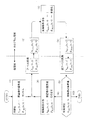
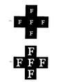
第2の問題は、再生像領域30の周りに再生される高次像である。計算機ホログラム20はx軸方向寸法δx 、y軸方向寸法δy のセル21が碁盤目状に配置されているものであり、x軸方向に格子間隔δx の回折格子、y軸方向に格子間隔δy の回折格子がその位相分布φHOLO(u,v)に重畳しているのと同じである。そのため、このx軸方向には格子間隔δx の回折格子がキャリア(搬送波)、y軸方向には格子間隔δy の回折格子がキャリア(搬送波)となって±1次の不要回折光が発生し、そのキャリアが再生像領域30に再生される本来のパターン「F」の周りであって、再生像領域30に隣接する領域に、図5に示すように、本来の再生像「F」と同じパターンの4つの高次像「F」が再生される。図5(a)は、再生像領域30(黒縦棒と黒横棒が交差している矩形領域が対応する。)の縦横共1/2以下の範囲内内にパターン「F」が再生されるように記録された場合、図5(b)は、再生像領域30(黒縦棒と黒横棒が交差している矩形領域が対応する。)の縦横共2/3以上の範囲内内にパターン「F」が再生されるように記録された場合に再生される像を示す。
【0031】
この図5(a)と(b)を比較して明らかなように、再生像領域30略全域に再現されるパターンを計算機ホログラム20に記録すると、図5(b)に示すように、再生像領域30に再生される本来のパターン「F」の周りに再生される高次像が近すぎて目立ち邪魔になり、望ましくない。これに対して、再生像領域30の縦横共1/2以下の範囲内に再現されるパターンを計算機ホログラム20に記録すると、図5(a)に示すように、再生像領域30に再生される本来のパターン「F」の周りに再生される高次像が相対的に遠くなり、余り目立たなく邪魔にならない。
【0032】
第3の問題は、計算機ホログラム20の多値化した位相分布φHOLO(u,v)をフォトリソグラフィーの手法を用いて作製するときのフォトマスクに関するものである。図6は、それぞれ(a1)、(a2)に示す原画を位相分布φHOLO(u,v)のみを持つフーリエ変換ホログラムとして4段階に多値化して記録するときの2個のフォトマスクを示す図であり、(b1)、(b2)はそれぞれ位相変調πを与えるためのフォトマスクのパターン、(c1)、(c2)はそれぞれ位相変調π/2を与えるためのフォトマスクのパターンであり、この例では、縦横共32個に分割してある。図6(a1)の原画は、再生像領域30の縦横共1/2以下の範囲内に再現される原画パターンであり、図6(a2)は縦横共1/2を越える範囲内に再現される原画パターンである。
【0033】
なお、位相変調πを与えるフォトマスク((b1)、(b2))と位相変調π/2を与えるフォトマスク((c1)、(c2))とを用いて位相分布を4段階に多値化するには、例えば、ポジ型レジストを用いて2回のパターン露光と透明基板17のエッチングを行う場合には、位相変調πのフォトマスクの開口部と位相変調π/2のフォトマスクの開口部とが重なるように露光することにより3π/2の位相部が得られ、位相変調πのフォトマスクの開口部と位相変調π/2のフォトマスクの遮光部とが重なるように露光することによりπの位相部が得られ、位相変調πのフォトマスクの遮光部と位相変調π/2のフォトマスクの開口部とが重なるように露光することによりπ/2の位相部が得られ、位相変調πのフォトマスクの遮光部と位相変調π/2のフォトマスクの遮光部とが重なるように露光することにより0の位相部が得られることになる。
【0034】
この図6(a1)〜(c1)と(a2)〜(c2)を比較して明らかなように、(a2)〜(c2)の場合には、(b2)に矢印で示してあるように、計算機ホログラム20を作製するためのフォトマスクに孤立パターンが発生しやすい。これに対して、(a1)〜(c1)の場合は、そのような孤立パターンはほとんど発生しない。フォトマスクにこのような孤立パターンが存在すると、その描画あるいは転写の際に孤立パターンの角が取れて丸まり、それを用いて作製された計算機ホログラム20のパターン再現性が悪くなったりノイズ光が増える等の問題が生じる。
【0035】
以上のように、第1から第3の何れの点から見ても、計算機ホログラム20の微小なセル21のピッチδx 、δy の2倍2δx 、2δy の格子間隔を持つ回折格子の±1次回折光で挟まれる範囲で定義される計算機ホログラム20の再生像領域30の2/3以下、望ましくは1/2以下の範囲内に再現される原画パターンを計算機ホログラム20に記録するようにすることにより、明るく、共役像、高次像が目立たないパターンが、メガネを通して見ているシーン中の光源に置き替わって見え、かつ、所定の特性のものの作製が容易な、ホログラムメガネ用の計算機ホログラムからなるフーリエ変換ホログラムが得られる。
【0036】
以上、本発明によるホログラムメガネとそのための計算機ホログラムを実施例に基づいて説明してきたが、これらに限定されず種々の変形が可能である。なお、本発明の計算機ホログラムは、片目用のホログラムメガネに用いることも含むものであり、さらには、ホログラムメガネ用に限らず、窓用あるいはディスプレイ用等に用いることもできるものである。
【0037】
【発明の効果】
以上の説明から明らかなように、本発明のホログラム観察具とそのための計算機ホログラムによると、計算機ホログラムを構成する微小なセルのピッチδx 、δy の2倍2δx 、2δy の格子間隔を持つ回折格子の所定波長の±1次回折光で挟まれる範囲で定義される計算機ホログラムの再生像領域の1/2以下の範囲内にその波長で再現される原画パターンが記録されているので、明るく、共役像、高次像が目立たないパターンが、観察具を通して見ているシーン中の光源に置き替わって見え、かつ、所定の特性のものの作製が容易な、ホログラム観察具用の計算機ホログラムからなるフーリエ変換ホログラムが得られる。
【図面の簡単な説明】
【図1】本発明のホログラムメガネの枠に嵌め込まれる計算機ホログラムとそれから再現される像領域とを模式的に示す図である。
【図2】本発明の計算機ホログラムを得るためのフローチャートである。
【図3】本発明の計算機ホログラムの構成例を示す断面図である。
【図4】再生像領域内のパターン再生範囲の例を示す図である。
【図5】再生像領域に再生される本来の再生パターンとその周りの4つの高次像とを示す図である。
【図6】原画とその原画パターンに対応する位相変調を与えるためのフォトマスクのパターンとを示す図である。
【図7】ホログラムメガネとその作用を説明するための図である。
【符号の説明】
1…メガネフレーム
2、3…透過型ホログラム
4、5、6、7…小面積の光源
8、9、10、11…予め選択された置き替えパターン
15…平行光
16…回折光
17…透明基板
18…レリーフパターン
20…計算機ホログラム(ホログラム面)
21…セル
30…像領域(再生像面)
31…セル
35…パターン再生範囲[0001]
BACKGROUND OF THE INVENTION
The present invention relates to a hologram observation tool and a computer generated hologram therefor, and more particularly, to a hologram hologram that is easy to make and has a bright and stable image viewed through the hologram glasses and a computer generated hologram therefor.
[0002]
[Prior art]
In
[Patent Document 1]
US Pat. No. 5,546,198 [Non-Patent Document 1]
Textbook "Holograms and diffractive optical elements-from basic theory to industrial application" sponsored by The Optical Society of Japan (Applied Physics Society) pp. 36-39
[0003]
[Problems to be solved by the invention]
A Fourier transform hologram obtained by a computer corresponds to a cell position by dividing a limited rectangular area including a pattern ("NOEL" in the above example) recorded in the hologram into a grid-like cell vertically and horizontally. Each cell is provided with information on the pattern portion, and a pattern consisting of a limited number of cells is projected by Fourier transform onto a distant hologram area. In fact, the hologram area is also recorded. Similar to the pattern area, it is divided into cells in a grid pattern in the vertical and horizontal directions, and the amplitude information and phase information of each cell position subjected to Fourier transform of the pattern to be recorded are recorded.
[0004]
As described above, a Fourier transform computer generated hologram in which a preselected pattern is recorded is composed of a finite number of cells. Therefore, the diffraction efficiency is not necessarily high, and the pattern seen through the hologram glasses is not necessarily bright. Further, the conjugate image appears to overlap the pattern, and further, a high-order diffraction image is seen close to the periphery of the main pattern, so that it cannot be said that it is easy to see and has sufficient characteristics.
[0005]
In addition, for the production of such a computer generated hologram, a photolithographic technique using a mask produced by fast Fourier transform is used. However, since the drawing pattern of the mask is very fine, a predetermined pattern can be stably formed. It is not easy to produce a computer generated hologram that reproduces.
[0006]
The present invention has been made in view of such problems of the prior art, and its purpose is to produce a high-diffraction-efficient, bright pattern that replaces the light source in the scene, resulting in a conjugate image and a higher-order image. Another object of the present invention is to provide a hologram observation tool and a computer generated hologram therefor that can be easily manufactured with predetermined characteristics.
[0007]
[Means for Solving the Problems]
The hologram observation tool of the present invention that achieves the above object is a hologram observation tool that is configured as a transmission type Fourier transform hologram and includes a computer generated hologram. The computer generated hologram includes a pitch δ x of a minute cell that forms the computer generated hologram. , Δ y , 2δ x , 2δ y , and a diffraction grating having a lattice interval of ± 1st order diffracted light of a predetermined wavelength defined by the range sandwiched by ± 1st order diffracted light within a range of 1/2 or less of the reproduced image region It is characterized in that an original picture pattern reproduced at a wavelength is recorded.
[0009]
In this case, the computer generated hologram is preferably a phase hologram.
[0010]
Further, it is desirable that the phase distribution of the computer generated hologram is multivalued in four or more stages.
[0011]
The computer generated hologram of the present invention is configured as a transmission type Fourier transform hologram for an observation tool. In the computer generated hologram for a hologram observation tool, the pitches δ x and δ y of the minute cells constituting the computer hologram are two times 2δ x. An original pattern reproduced at the wavelength within a range of 1/2 or less of the reproduced image area of the computer generated hologram defined by the range sandwiched by the ± 1st order diffracted light of the predetermined wavelength of the diffraction grating having a grating interval of 2δ y It is characterized by being recorded.
[0013]
In this case, the computer generated hologram is preferably a phase hologram.
[0014]
Moreover, it is desirable that the phase distribution is multi-valued in four or more stages.
[0015]
In the present invention, the definition is made within a range sandwiched between ± 1st order diffracted lights of a predetermined wavelength of a diffraction grating having a grating interval of 2δ x , 2δ y , which is twice the pitch δ x and δ y of a minute cell constituting a computer generated hologram. Since the original image pattern reproduced at that wavelength is recorded in the range of 1/2 or less of the reconstructed image area of the computer hologram to be viewed, a bright, conjugated image and a high-order image inconspicuous pattern can be seen through the observation tool. Thus, a Fourier transform hologram composed of a computer generated hologram for a hologram observation tool that can be easily replaced with a light source in a scene and that has a predetermined characteristic can be easily obtained.
[0016]
DETAILED DESCRIPTION OF THE INVENTION
Hereinafter, embodiments of the hologram observation tool of the present invention and a computer generated hologram therefor will be described.
[0017]
FIG. 1 schematically shows a computer generated hologram 20 (corresponding to the
[0018]
On the other hand, the
[0019]
The x-axis direction length L x and the y-axis direction length L y of the
[0020]
With this arrangement relationship, when parallel light 15 having a predetermined wavelength is incident from the front of the computer generated
[0021]
An embodiment will be described in which the phase information of each
[0022]
Here, for easy understanding, the amplitude distribution (pixel value) of the original image on the reproduced
[0023]
In addition, the process of multi- leveling the phase distribution φ HOLO (u, v) is not performed in step (3), and a predetermined multi-level process is performed after the condition of step (5) is satisfied. Also good.
[0024]
The depth distribution of the actual hologram is obtained from the multi-valued phase distribution φ HOLO (u, v) obtained in this way. In the case of a transmission type like the present invention, the following equation (1) is obtained. Based on this, the depth is converted to the depth D (x, y) of the computer generated
[0025]
D (u, v) = λφ HOLO (u, v) / {2π (n 1 −n 0 )} (1) where λ is the center wavelength used, and n 1 and n 0 are transmission holograms. It is the refractive index of the two materials which comprise. Then, as illustrated in the cross-sectional view of FIG. 3, by forming a
[0026]
By the way, as described above, the computer generated
[0027]
The first is that if the size of the reproduction pattern occupied in the
[0028]
Here, in order to record in the computer generated
[0029]
Therefore, when recording is made on the computer generated
[0030]
The second problem is a higher-order image reproduced around the reproduced
[0031]
As is clear from comparison between FIGS. 5A and 5B, when a pattern reproduced on the entire
[0032]
The third problem relates to a photomask when the multi-valued phase distribution φ HOLO (u, v) of the computer generated
[0033]
The phase distribution is multi-valued in four stages using a photomask ((b1), (b2)) that provides phase modulation π and a photomask ((c1), (c2)) that provides phase modulation π / 2. For example, when performing pattern exposure twice and etching the
[0034]
As is clear from comparison of FIGS. 6 (a1) to (c1) and (a2) to (c2), in the case of (a2) to (c2), as indicated by arrows in (b2). An isolated pattern is likely to occur in a photomask for producing the computer generated
[0035]
As described above, when viewed from any of the first to third points, the diffraction grating having a lattice spacing of 2δ x , 2δ y , twice the pitch δ x , δ y of the
[0036]
The hologram glasses according to the present invention and the computer generated holograms therefor have been described based on the embodiments. However, the present invention is not limited to these, and various modifications are possible. In addition, the computer generated hologram of the present invention includes use for hologram glasses for one eye, and can be used not only for hologram glasses but also for windows or displays.
[0037]
【The invention's effect】
As is clear from the above description, according to the hologram observation tool of the present invention and the computer generated hologram therefor, the lattice spacing of 2δ x , 2δ y , which is twice the pitches δ x and δ y of the minute cells constituting the computer hologram, is obtained. Since the original pattern reproduced at that wavelength is recorded in the range of 1/2 or less of the reproduced image area of the computer generated hologram defined by the range sandwiched by the ± 1st order diffracted light of the predetermined wavelength of the diffraction grating possessed, it is bright Consists of computer-generated holograms for holographic observation tools, in which a conspicuous image or a high-order image is inconspicuous, can be replaced with a light source in a scene viewed through the observation tool, and can be easily manufactured with a predetermined characteristic A Fourier transform hologram is obtained.
[Brief description of the drawings]
FIG. 1 is a diagram schematically showing a computer generated hologram fitted in a frame of hologram glasses of the present invention and an image area reproduced therefrom.
FIG. 2 is a flowchart for obtaining a computer generated hologram of the present invention.
FIG. 3 is a cross-sectional view showing a configuration example of a computer generated hologram according to the present invention.
FIG. 4 is a diagram illustrating an example of a pattern reproduction range in a reproduction image area.
FIG. 5 is a diagram showing an original reproduction pattern reproduced in a reproduction image area and four higher-order images around it.
FIG. 6 is a diagram showing an original picture and a photomask pattern for applying phase modulation corresponding to the original picture pattern.
FIG. 7 is a diagram for explaining hologram glasses and their operation.
[Explanation of symbols]
DESCRIPTION OF
21 ...
31 ...
Claims (6)
Priority Applications (1)
| Application Number | Priority Date | Filing Date | Title |
|---|---|---|---|
| JP2003205316A JP4360526B2 (en) | 2002-08-02 | 2003-08-01 | Hologram observation tool and computer generated hologram therefor |
Applications Claiming Priority (2)
| Application Number | Priority Date | Filing Date | Title |
|---|---|---|---|
| JP2002225605 | 2002-08-02 | ||
| JP2003205316A JP4360526B2 (en) | 2002-08-02 | 2003-08-01 | Hologram observation tool and computer generated hologram therefor |
Publications (3)
| Publication Number | Publication Date |
|---|---|
| JP2004126535A JP2004126535A (en) | 2004-04-22 |
| JP2004126535A5 JP2004126535A5 (en) | 2006-08-10 |
| JP4360526B2 true JP4360526B2 (en) | 2009-11-11 |
Family
ID=32300767
Family Applications (1)
| Application Number | Title | Priority Date | Filing Date |
|---|---|---|---|
| JP2003205316A Expired - Lifetime JP4360526B2 (en) | 2002-08-02 | 2003-08-01 | Hologram observation tool and computer generated hologram therefor |
Country Status (1)
| Country | Link |
|---|---|
| JP (1) | JP4360526B2 (en) |
Families Citing this family (7)
| Publication number | Priority date | Publication date | Assignee | Title |
|---|---|---|---|---|
| JP2006126791A (en) * | 2004-09-28 | 2006-05-18 | Dainippon Printing Co Ltd | Hologram and holographic viewing device incorporating the same |
| JP4821964B2 (en) * | 2005-07-04 | 2011-11-24 | 大日本印刷株式会社 | Hologram observation tool |
| US8941904B2 (en) | 2005-07-04 | 2015-01-27 | Dai Nippon Printing Co., Ltd. | Hologram sheet and hologram observation sheet using same, and blinding device |
| JP4821192B2 (en) * | 2005-07-06 | 2011-11-24 | 大日本印刷株式会社 | Computer generated hologram optical element |
| JP4753152B2 (en) * | 2005-07-06 | 2011-08-24 | 大日本印刷株式会社 | Transparent card with hologram and transparent card recognition device with hologram |
| JP4984938B2 (en) * | 2007-02-07 | 2012-07-25 | 大日本印刷株式会社 | Optical element and manufacturing method thereof |
| WO2018097238A1 (en) | 2016-11-24 | 2018-05-31 | 大日本印刷株式会社 | Light modulation element and information recording medium |
-
2003
- 2003-08-01 JP JP2003205316A patent/JP4360526B2/en not_active Expired - Lifetime
Also Published As
| Publication number | Publication date |
|---|---|
| JP2004126535A (en) | 2004-04-22 |
Similar Documents
| Publication | Publication Date | Title |
|---|---|---|
| TWI437388B (en) | Method and holographic projection display with corrected phase encoding | |
| JP5266223B2 (en) | Method for generating computer video holograms in real time using propagation | |
| US9606507B2 (en) | Method for integrating a synthetic hologram in a halftone image | |
| JP4360526B2 (en) | Hologram observation tool and computer generated hologram therefor | |
| US6961159B2 (en) | Holographic viewing device, and computer-generated hologram for the same | |
| US6825959B2 (en) | Holographic viewing device, and computer-generated hologram for the same | |
| JP3951554B2 (en) | Computer generated hologram | |
| KR101292370B1 (en) | Three dimensional image display apparatus using digital hologram | |
| WO2001014937A1 (en) | Volume holograms in transparent materials | |
| JP5206915B2 (en) | Blindfold device and method for manufacturing blindfold device | |
| JP4620220B2 (en) | Computer generated hologram and method for manufacturing the same | |
| KR20190115215A (en) | Apparatus for Holographic Display, Hologram Optical System and Method for Recording Hologram | |
| JP4367750B2 (en) | Hologram observation tool and computer generated hologram therefor | |
| JP4371302B2 (en) | Hologram observation tool and computer generated hologram therefor | |
| Koreshev et al. | How the method of representing an object affects the imaging properties of synthesized holograms | |
| Wu et al. | 7‐1: Computer generated hologram accelerated by using hybrid iterative Fourier transform algorithm (HIFTA) on phase modulator LCOS | |
| US20040027628A1 (en) | Holographic viewing device, and computer-generated hologram for the same | |
| JP3925047B2 (en) | Computer generated hologram and method for producing the same | |
| JP3948199B2 (en) | Computer generated hologram and method for producing the same | |
| Carbonell-Leal et al. | Encoding complex fields by using a phase-only optical element: mitigation of pixel crosstalk effects | |
| Kitamura et al. | Computer-generated holograms for multilevel 3d images with complex amplitude modulation | |
| JP2000089014A (en) | Phase mask for processing optical fiber and manufacture thereof | |
| JP2024509951A (en) | Security device and its manufacturing method | |
| Oh et al. | Full Complex Hologram Representation Method Using DOE Phase Mask | |
| JP2002250808A (en) | Cgh diffraction grating hybrid display body and computer program to be executed for manufacturing of the body |
Legal Events
| Date | Code | Title | Description |
|---|---|---|---|
| A521 | Request for written amendment filed |
Free format text: JAPANESE INTERMEDIATE CODE: A523 Effective date: 20060627 |
|
| A621 | Written request for application examination |
Free format text: JAPANESE INTERMEDIATE CODE: A621 Effective date: 20060627 |
|
| A977 | Report on retrieval |
Free format text: JAPANESE INTERMEDIATE CODE: A971007 Effective date: 20090424 |
|
| A131 | Notification of reasons for refusal |
Free format text: JAPANESE INTERMEDIATE CODE: A131 Effective date: 20090513 |
|
| A521 | Request for written amendment filed |
Free format text: JAPANESE INTERMEDIATE CODE: A523 Effective date: 20090708 |
|
| TRDD | Decision of grant or rejection written | ||
| A01 | Written decision to grant a patent or to grant a registration (utility model) |
Free format text: JAPANESE INTERMEDIATE CODE: A01 Effective date: 20090805 |
|
| A01 | Written decision to grant a patent or to grant a registration (utility model) |
Free format text: JAPANESE INTERMEDIATE CODE: A01 |
|
| A61 | First payment of annual fees (during grant procedure) |
Free format text: JAPANESE INTERMEDIATE CODE: A61 Effective date: 20090806 |
|
| R150 | Certificate of patent or registration of utility model |
Free format text: JAPANESE INTERMEDIATE CODE: R150 Ref document number: 4360526 Country of ref document: JP Free format text: JAPANESE INTERMEDIATE CODE: R150 |
|
| FPAY | Renewal fee payment (event date is renewal date of database) |
Free format text: PAYMENT UNTIL: 20120821 Year of fee payment: 3 |
|
| FPAY | Renewal fee payment (event date is renewal date of database) |
Free format text: PAYMENT UNTIL: 20120821 Year of fee payment: 3 |
|
| FPAY | Renewal fee payment (event date is renewal date of database) |
Free format text: PAYMENT UNTIL: 20130821 Year of fee payment: 4 |
|
| EXPY | Cancellation because of completion of term |