JP4358589B2 - Medical treatment tool - Google Patents
Medical treatment tool Download PDFInfo
- Publication number
- JP4358589B2 JP4358589B2 JP2003349571A JP2003349571A JP4358589B2 JP 4358589 B2 JP4358589 B2 JP 4358589B2 JP 2003349571 A JP2003349571 A JP 2003349571A JP 2003349571 A JP2003349571 A JP 2003349571A JP 4358589 B2 JP4358589 B2 JP 4358589B2
- Authority
- JP
- Japan
- Prior art keywords
- wire
- cutting
- sheath
- medical treatment
- distal end
- Prior art date
- Legal status (The legal status is an assumption and is not a legal conclusion. Google has not performed a legal analysis and makes no representation as to the accuracy of the status listed.)
- Expired - Fee Related
Links
- 238000005520 cutting process Methods 0.000 claims description 219
- 230000003014 reinforcing effect Effects 0.000 claims description 10
- 239000004615 ingredient Substances 0.000 claims 1
- 238000003780 insertion Methods 0.000 description 30
- 230000037431 insertion Effects 0.000 description 30
- 210000001519 tissue Anatomy 0.000 description 18
- 238000005286 illumination Methods 0.000 description 9
- 239000002184 metal Substances 0.000 description 9
- 210000003811 finger Anatomy 0.000 description 8
- 210000000078 claw Anatomy 0.000 description 7
- 230000003902 lesion Effects 0.000 description 7
- 238000005452 bending Methods 0.000 description 6
- 239000000463 material Substances 0.000 description 6
- 230000002093 peripheral effect Effects 0.000 description 6
- 229910001220 stainless steel Inorganic materials 0.000 description 6
- 239000010935 stainless steel Substances 0.000 description 6
- 210000004400 mucous membrane Anatomy 0.000 description 5
- 239000000835 fiber Substances 0.000 description 4
- 238000003384 imaging method Methods 0.000 description 4
- 238000000034 method Methods 0.000 description 4
- -1 polyethylene Polymers 0.000 description 3
- 238000003860 storage Methods 0.000 description 3
- 239000004698 Polyethylene Substances 0.000 description 2
- 230000000740 bleeding effect Effects 0.000 description 2
- 230000017531 blood circulation Effects 0.000 description 2
- 238000010586 diagram Methods 0.000 description 2
- 229920001971 elastomer Polymers 0.000 description 2
- 229920002457 flexible plastic Polymers 0.000 description 2
- 210000004877 mucosa Anatomy 0.000 description 2
- 230000003287 optical effect Effects 0.000 description 2
- 239000004033 plastic Substances 0.000 description 2
- 229920003023 plastic Polymers 0.000 description 2
- 229920000573 polyethylene Polymers 0.000 description 2
- 239000004810 polytetrafluoroethylene Substances 0.000 description 2
- 229920001343 polytetrafluoroethylene Polymers 0.000 description 2
- YCKRFDGAMUMZLT-UHFFFAOYSA-N Fluorine atom Chemical compound [F] YCKRFDGAMUMZLT-UHFFFAOYSA-N 0.000 description 1
- 239000004677 Nylon Substances 0.000 description 1
- 229930182556 Polyacetal Natural products 0.000 description 1
- 239000004743 Polypropylene Substances 0.000 description 1
- 229920000122 acrylonitrile butadiene styrene Polymers 0.000 description 1
- 230000001154 acute effect Effects 0.000 description 1
- 239000012472 biological sample Substances 0.000 description 1
- 230000005540 biological transmission Effects 0.000 description 1
- 230000007423 decrease Effects 0.000 description 1
- 230000003247 decreasing effect Effects 0.000 description 1
- 230000000593 degrading effect Effects 0.000 description 1
- 229910052731 fluorine Inorganic materials 0.000 description 1
- 239000011737 fluorine Substances 0.000 description 1
- 210000001035 gastrointestinal tract Anatomy 0.000 description 1
- 230000002439 hemostatic effect Effects 0.000 description 1
- 238000004519 manufacturing process Methods 0.000 description 1
- 238000012986 modification Methods 0.000 description 1
- 230000004048 modification Effects 0.000 description 1
- 229920001778 nylon Polymers 0.000 description 1
- 230000000149 penetrating effect Effects 0.000 description 1
- 229920000515 polycarbonate Polymers 0.000 description 1
- 239000004417 polycarbonate Substances 0.000 description 1
- 229920000098 polyolefin Polymers 0.000 description 1
- 229920006324 polyoxymethylene Polymers 0.000 description 1
- 229920001155 polypropylene Polymers 0.000 description 1
- 238000003825 pressing Methods 0.000 description 1
- 230000002787 reinforcement Effects 0.000 description 1
- 229920002379 silicone rubber Polymers 0.000 description 1
- 229920003002 synthetic resin Polymers 0.000 description 1
- 239000000057 synthetic resin Substances 0.000 description 1
- 229920002725 thermoplastic elastomer Polymers 0.000 description 1
- 210000003813 thumb Anatomy 0.000 description 1
Images


Classifications
-
- A—HUMAN NECESSITIES
- A61—MEDICAL OR VETERINARY SCIENCE; HYGIENE
- A61B—DIAGNOSIS; SURGERY; IDENTIFICATION
- A61B17/00—Surgical instruments, devices or methods, e.g. tourniquets
- A61B17/04—Surgical instruments, devices or methods, e.g. tourniquets for suturing wounds; Holders or packages for needles or suture materials
- A61B17/0401—Suture anchors, buttons or pledgets, i.e. means for attaching sutures to bone, cartilage or soft tissue; Instruments for applying or removing suture anchors
-
- A—HUMAN NECESSITIES
- A61—MEDICAL OR VETERINARY SCIENCE; HYGIENE
- A61B—DIAGNOSIS; SURGERY; IDENTIFICATION
- A61B17/00—Surgical instruments, devices or methods, e.g. tourniquets
- A61B17/12—Surgical instruments, devices or methods, e.g. tourniquets for ligaturing or otherwise compressing tubular parts of the body, e.g. blood vessels, umbilical cord
- A61B17/12009—Implements for ligaturing other than by clamps or clips, e.g. using a loop with a slip knot
- A61B17/12013—Implements for ligaturing other than by clamps or clips, e.g. using a loop with a slip knot for use in minimally invasive surgery, e.g. endoscopic surgery
-
- A—HUMAN NECESSITIES
- A61—MEDICAL OR VETERINARY SCIENCE; HYGIENE
- A61B—DIAGNOSIS; SURGERY; IDENTIFICATION
- A61B17/00—Surgical instruments, devices or methods, e.g. tourniquets
- A61B17/04—Surgical instruments, devices or methods, e.g. tourniquets for suturing wounds; Holders or packages for needles or suture materials
- A61B17/0467—Instruments for cutting sutures
-
- A—HUMAN NECESSITIES
- A61—MEDICAL OR VETERINARY SCIENCE; HYGIENE
- A61B—DIAGNOSIS; SURGERY; IDENTIFICATION
- A61B17/00—Surgical instruments, devices or methods, e.g. tourniquets
- A61B17/04—Surgical instruments, devices or methods, e.g. tourniquets for suturing wounds; Holders or packages for needles or suture materials
- A61B17/0487—Suture clamps, clips or locks, e.g. for replacing suture knots; Instruments for applying or removing suture clamps, clips or locks
-
- A—HUMAN NECESSITIES
- A61—MEDICAL OR VETERINARY SCIENCE; HYGIENE
- A61B—DIAGNOSIS; SURGERY; IDENTIFICATION
- A61B17/00—Surgical instruments, devices or methods, e.g. tourniquets
- A61B17/04—Surgical instruments, devices or methods, e.g. tourniquets for suturing wounds; Holders or packages for needles or suture materials
- A61B17/0401—Suture anchors, buttons or pledgets, i.e. means for attaching sutures to bone, cartilage or soft tissue; Instruments for applying or removing suture anchors
- A61B2017/0404—Buttons
-
- A—HUMAN NECESSITIES
- A61—MEDICAL OR VETERINARY SCIENCE; HYGIENE
- A61B—DIAGNOSIS; SURGERY; IDENTIFICATION
- A61B17/00—Surgical instruments, devices or methods, e.g. tourniquets
- A61B17/04—Surgical instruments, devices or methods, e.g. tourniquets for suturing wounds; Holders or packages for needles or suture materials
- A61B17/0401—Suture anchors, buttons or pledgets, i.e. means for attaching sutures to bone, cartilage or soft tissue; Instruments for applying or removing suture anchors
- A61B2017/0409—Instruments for applying suture anchors
-
- A—HUMAN NECESSITIES
- A61—MEDICAL OR VETERINARY SCIENCE; HYGIENE
- A61B—DIAGNOSIS; SURGERY; IDENTIFICATION
- A61B17/00—Surgical instruments, devices or methods, e.g. tourniquets
- A61B17/04—Surgical instruments, devices or methods, e.g. tourniquets for suturing wounds; Holders or packages for needles or suture materials
- A61B17/0401—Suture anchors, buttons or pledgets, i.e. means for attaching sutures to bone, cartilage or soft tissue; Instruments for applying or removing suture anchors
- A61B2017/0417—T-fasteners
-
- A—HUMAN NECESSITIES
- A61—MEDICAL OR VETERINARY SCIENCE; HYGIENE
- A61B—DIAGNOSIS; SURGERY; IDENTIFICATION
- A61B17/00—Surgical instruments, devices or methods, e.g. tourniquets
- A61B17/04—Surgical instruments, devices or methods, e.g. tourniquets for suturing wounds; Holders or packages for needles or suture materials
- A61B17/0401—Suture anchors, buttons or pledgets, i.e. means for attaching sutures to bone, cartilage or soft tissue; Instruments for applying or removing suture anchors
- A61B2017/0446—Means for attaching and blocking the suture in the suture anchor
- A61B2017/0458—Longitudinal through hole, e.g. suture blocked by a distal suture knot
-
- A—HUMAN NECESSITIES
- A61—MEDICAL OR VETERINARY SCIENCE; HYGIENE
- A61B—DIAGNOSIS; SURGERY; IDENTIFICATION
- A61B17/00—Surgical instruments, devices or methods, e.g. tourniquets
- A61B17/04—Surgical instruments, devices or methods, e.g. tourniquets for suturing wounds; Holders or packages for needles or suture materials
- A61B17/0401—Suture anchors, buttons or pledgets, i.e. means for attaching sutures to bone, cartilage or soft tissue; Instruments for applying or removing suture anchors
- A61B2017/0464—Suture anchors, buttons or pledgets, i.e. means for attaching sutures to bone, cartilage or soft tissue; Instruments for applying or removing suture anchors for soft tissue
-
- A—HUMAN NECESSITIES
- A61—MEDICAL OR VETERINARY SCIENCE; HYGIENE
- A61B—DIAGNOSIS; SURGERY; IDENTIFICATION
- A61B17/00—Surgical instruments, devices or methods, e.g. tourniquets
- A61B17/04—Surgical instruments, devices or methods, e.g. tourniquets for suturing wounds; Holders or packages for needles or suture materials
- A61B2017/0496—Surgical instruments, devices or methods, e.g. tourniquets for suturing wounds; Holders or packages for needles or suture materials for tensioning sutures
-
- A—HUMAN NECESSITIES
- A61—MEDICAL OR VETERINARY SCIENCE; HYGIENE
- A61B—DIAGNOSIS; SURGERY; IDENTIFICATION
- A61B17/00—Surgical instruments, devices or methods, e.g. tourniquets
- A61B17/04—Surgical instruments, devices or methods, e.g. tourniquets for suturing wounds; Holders or packages for needles or suture materials
- A61B17/06—Needles ; Sutures; Needle-suture combinations; Holders or packages for needles or suture materials
- A61B2017/06052—Needle-suture combinations in which a suture is extending inside a hollow tubular needle, e.g. over the entire length of the needle
Landscapes
- Health & Medical Sciences (AREA)
- Surgery (AREA)
- Life Sciences & Earth Sciences (AREA)
- Medical Informatics (AREA)
- Animal Behavior & Ethology (AREA)
- Engineering & Computer Science (AREA)
- Biomedical Technology (AREA)
- Heart & Thoracic Surgery (AREA)
- Veterinary Medicine (AREA)
- Molecular Biology (AREA)
- Nuclear Medicine, Radiotherapy & Molecular Imaging (AREA)
- General Health & Medical Sciences (AREA)
- Public Health (AREA)
- Reproductive Health (AREA)
- Vascular Medicine (AREA)
- Rheumatology (AREA)
- Surgical Instruments (AREA)
Description
本発明は、体腔内に挿入し、生体組織に対して所定処理、例えば、結紮や縫合等を行う医療用処置具に関する。 The present invention relates to a medical treatment instrument that is inserted into a body cavity and performs predetermined processing, for example, ligation or suturing, on a living tissue.
現在、内視鏡の処置具チャンネルに挿通することにより体腔内に挿入し、生体組織に対して、所定の処理、例えば、結紮、縫合、生体サンプルの入手を行う医療用処置具は、様々なものが提供されている。この種の医療用処置具の1つとして、体腔内の病変部を結紮ワイヤにより結紮すると共に結紮した該結紮ワイヤを切断する操作を、一連の操作で行うことができる医療用結紮装置が知られている(例えば、特許文献1参照)。
この医療用結紮装置は、生体内に留置される医療用結紮具と、該医療用結紮具を体内に誘導して結紮操作を行う操作装置とを備えている。医療用結紮具は、基端側に折り返し部を有する上記結紮ワイヤと、該結紮ワイヤを折り返し部の前方で進退自在に保持する受け部材とを有している。また、該受け部材は、軸方向の略中央部に環状突起部を有しており、結紮ワイヤを外部に露出させると共に後述する切断刃の突き当て面とされている。
At present, there are various medical treatment tools that are inserted into a body cavity by being inserted into a treatment tool channel of an endoscope, and perform predetermined processing, such as ligation, suturing, and acquisition of a biological sample, on a biological tissue. Things are offered. As one type of medical treatment tool of this type, there is known a medical ligation apparatus capable of performing a series of operations for ligating a lesion in a body cavity with a ligation wire and cutting the ligated wire. (For example, refer to Patent Document 1).
This medical ligation apparatus includes a medical ligation tool that is placed in a living body, and an operation device that guides the medical ligation tool into the body and performs a ligation operation. The medical ligation tool includes the ligation wire having a folded portion on the base end side, and a receiving member that holds the ligature wire in a forward and backward manner in front of the folded portion. In addition, the receiving member has an annular protrusion at a substantially central portion in the axial direction, and exposes the ligating wire to the outside and serves as an abutting surface of a cutting blade described later.
上記操作装置は、上記受け部材の基端側に当接する内側シースを有しており、該内側シースの基端側は、操作部本体を介して指かけリングが接続されている。なお、受け部材は、内側シースの先端に嵌合している。また、操作部本体には、該操作部本体に対して進退自在なスライダが取り付けられており、該スライダには、内側シース内に挿通されて先端に係合部材を有する操作ワイヤが接続されている。この係合部材は、結紮ワイヤの上記折り返し部に係合するようになっている。即ち、操作部本体を固定した状態でスライダを進退操作することにより、結紮ワイヤを拡径又は縮径できるようになっている。
また、内側シースの周囲には、該内側シースを覆うと共に進退自在な切断用シースが設けられており、該切断用シースの基端側には、切断操作部が接続されている。なお、この切断操作部は、操作部本体の先端側に配され、基端方向には操作部本体に当接して移動できないようになっている。また、切断用シースの先端は、環状の上記切断刃が形成されている。
The operating device has an inner sheath that abuts on the proximal end side of the receiving member, and a finger ring is connected to the proximal end side of the inner sheath via an operating portion main body. The receiving member is fitted to the tip of the inner sheath. Further, a slider that can be moved forward and backward with respect to the operation unit main body is attached to the operation unit main body, and an operation wire that is inserted into the inner sheath and has an engagement member at the tip is connected to the slider. Yes. The engaging member is adapted to engage with the folded portion of the ligature wire. That is, the diameter of the ligature wire can be increased or decreased by moving the slider forward and backward while the operation unit body is fixed.
In addition, a cutting sheath that covers the inner sheath and is movable back and forth is provided around the inner sheath, and a cutting operation portion is connected to a proximal end side of the cutting sheath. The cutting operation unit is disposed on the distal end side of the operation unit main body, and cannot move in contact with the operation unit main body in the proximal direction. Further, the annular cutting blade is formed at the tip of the cutting sheath.
このように構成された医療用結紮装置により体腔内の病変部を結紮する場合には、まず、医療用結紮具を操作装置に装着する。即ち、結紮ワイヤの折り返し部を操作ワイヤの係合部材に引っ掛けると共に受け部材を内側シースの先端に嵌合させ、その後、スライダを基端方向に移動させることで、受け部材が内側シースに支持される。そして、内視鏡装置等を介して体腔内に挿入し、病変部に結紮ワイヤを引っ掛ける。この状態で、操作部本体を固定してスライダを基端方向に移動させて結紮ワイヤを縮径させる。こうすることで、病変部が緊縛されて血流を止めることができる。緊縛後、操作部本体を固定した状態で、切断操作部を先端方向に押す。つまり、切断用シースを内側シースに沿って先端方向に移動させる。これにより、切断用シース先端に形成された切断刃が、受け部材の環状突起部に向かって移動し、該環状突起部によって外部に露出した結紮ワイヤを切断する。なお、結紮ワイヤの切断後、切断刃は、環状突起部の突き当て面に当接する。これにより、病変部を緊縛した結紮ワイヤが切り離され、結紮処理が終了する。なお、受け部材は、結紮ワイヤが切断されると、内側シースから抜けて体内に脱落して、その後自然排出される。
しかしながら上記特許文献1記載の医療用結紮装置では、結紮ワイヤを切断するときに、操作部本体を固定した状態で切断操作部を先端方向に移動させて切断を行う必要がある。この際、結紮ワイヤを容易に切断できれば構わないが、切断状況によっては力を加えて切断操作部を押し出す必要がある。このとき、結紮ワイヤの切断後、切断操作部を押した勢いで、該切断操作部が操作部本体から先端方向に向けて移動しすぎてしまう可能性があった。つまり、操作部本体に接続されている内側シースが根元から飛び出してしまう恐れがあった。そのため、切断操作部を元の位置に戻すために、内側シースを切断操作部内、即ち、切断用シース内に送り込んで復旧させるという手間が生じていた。 However, in the medical ligation apparatus described in Patent Document 1, when cutting the ligation wire, it is necessary to perform cutting by moving the cutting operation unit in the distal direction with the operation unit main body fixed. At this time, it is only necessary to easily cut the ligature wire, but depending on the cutting situation, it is necessary to push the cutting operation portion by applying a force. At this time, after cutting the ligature wire, there is a possibility that the cutting operation unit may move too far from the operation unit main body in the distal direction with the force of pressing the cutting operation unit. That is, there is a possibility that the inner sheath connected to the operation unit main body may protrude from the root. Therefore, in order to return the cutting operation unit to the original position, there has been a trouble of returning the inner sheath into the cutting operation unit, that is, into the cutting sheath.
本発明は、このような事情を考慮してなされたものであって、その目的は、生体組織に対して所定処理後、結紮ワイヤ等の線材を確実に切断すると共に切断後に余計な手間をかけることのない医療用処置具を提供することである。 The present invention has been made in consideration of such circumstances, and its purpose is to reliably cut a wire material such as a ligature wire after a predetermined treatment on a living tissue and to take extra time after cutting. It is to provide a medical treatment instrument that does not have any problems.
上記目的を達成するために、本発明は、以下の手段を提供する。
請求項1に係る発明は、生体組織に対して所定処理を行う可撓性の線材と、該線材を覆って進退自在に設けられ、該線材を保持する線材保持部材と、該線材保持部材の基端側に当接して設けられた可撓性の第1のシースと、該第1のシースを覆って、第1のシース及び前記線材保持部材に対して進退自在に設けられた可撓性の第2のシースと、該第2のシースの基端側に接続され、第2のシースの進退操作を行う操作部と、前記線材を切断する切断手段とを備え、該切断手段が、前記線材保持部材に設けられた第1の切断用部と、前記第2のシースの先端に設けられて第1の切断用部より先端側に配されると共に該第1の切断用部との間で前記線材を挟持する第2の切断用部とを備え、第1の切断用部及び第2の切断用部の少なくとも一方が刃部である医療用処置具を提供する。
In order to achieve the above object, the present invention provides the following means.
According to a first aspect of the present invention, there is provided a flexible wire material that performs a predetermined process on a living tissue, a wire material holding member that covers the wire material and is capable of moving forward and backward, and that holds the wire material, and the wire material holding member. A flexible first sheath that is provided in contact with the proximal end side, and a flexibility that is provided so as to be able to advance and retreat with respect to the first sheath and the wire holding member so as to cover the first sheath The second sheath, an operation portion connected to the proximal end side of the second sheath and performing the advance / retreat operation of the second sheath, and a cutting means for cutting the wire, wherein the cutting means includes the Between the first cutting part provided on the wire holding member and the first cutting part provided at the tip of the second sheath and arranged on the tip side from the first cutting part. And a second cutting part for sandwiching the wire, and at least one of the first cutting part and the second cutting part is To provide a medical treatment instrument is part.
この発明に係る医療用処置具においては、線材により生態組織に対して所定処理が終了した後、操作部を基端方向に向けて引っ張るように操作し、第2のシースを第1のシースに対して後退させると、第2の切断用部が線材保持部材に設けられた第1の切断用部に向って移動する。そして、第1の切断用部と第2の切断用部との間で、線材を挟みながら刃部により、ハサミの如く線材の切断が行える。
このように、第2のシースの引っ張り操作によって、線材の切断が行えるので、第2のシース内から第1のシースが飛び出して露出することはない。従って、切断後、従来のように第1のシースを第2のシース内に復旧する等の手間をなくすことができる。また、両切断用部により線材を挟持しながら切断するので、容易且つ確実に線材を切断することができる。
In the medical treatment tool according to the present invention, after the predetermined processing is completed on the ecological tissue by the wire, the operation portion is operated so as to be pulled in the proximal direction, and the second sheath is changed to the first sheath. When retracted, the second cutting part moves toward the first cutting part provided on the wire holding member. Then, the wire rod can be cut like scissors by the blade portion while sandwiching the wire rod between the first cutting portion and the second cutting portion.
Thus, since the wire can be cut by the pulling operation of the second sheath, the first sheath does not jump out of the second sheath and is not exposed. Therefore, after cutting, it is possible to eliminate the trouble of restoring the first sheath into the second sheath as in the prior art. Moreover, since it cut | disconnects by pinching | interposing a wire with both the parts for a cutting | disconnection, a wire can be cut | disconnected easily and reliably.
請求項2に係る発明は、請求項1に記載の医療用処置具において、前記第1の切断用部が、前記線材を前記線材保持部材の内部から外部に導く先端案内部と、該先端案内部より外部に導かれた線材を再度内部に導く基端案内部とを有し、前記第2の切断用部が、前記先端案内部又は前記基端案内部との間で外部に露出した前記線材を挟持する位置に配される医療用処置具を提供する。
この発明に係る医療用処置具においては、第2のシースの引っ張り操作を行うと、第2の切断用部が移動して、線材保持部材の外部において、先端案内部又は基端案内部との間で線材を挟持しながら切断が行える。
The invention according to
In the medical treatment tool according to the present invention, when the second sheath is pulled, the second cutting portion moves, and the distal end guide portion or the proximal end guide portion is moved outside the wire holding member. Cutting can be performed while holding the wire in between.
請求項3に係る発明は、請求項2に記載の医療用処置具において、前記第2のシースの先端には、先端側に開口部を有すると共に、前記第2の切断用部に接続されて前記線材を挿通可能なスリットが形成されている医療用処置具を提供する。
この発明に係る医療用処置具においては、第2の切断用部を第1の切断用部よりも先端に位置させる際に、スリットを介して線材を該第2の切断用部に位置させることができる。つまり、スリットを介して線材を出し入れするように挿通させることで、線材を保持した線材保持部材と、第2のシースとを脱着させることができる。従って、線材の切断毎に、線材保持部材のみを交換することが可能である。
The invention according to
In the medical treatment tool according to the present invention, when the second cutting portion is positioned at the tip of the first cutting portion, the wire is positioned at the second cutting portion via the slit. Can do. That is, the wire holding member holding the wire and the second sheath can be detached by inserting the wire so as to be taken in and out through the slit. Therefore, it is possible to replace only the wire holding member every time the wire is cut.
請求項4に係る発明は、請求項2に記載の医療用処置具において、前記第2の切断用部が、第2のシースに着脱自在な切断用部材に設けられている医療用処置具を提供する。
この発明に係る医療用処置具においては、切断用部材が着脱自在であるため、切断毎に、線材保持部材のみならず、切断用部材までも交換することができる。従って、切断性を低下させることなく、切れ味を維持することができる。
The invention according to
In the medical treatment instrument according to the present invention, since the cutting member is detachable, not only the wire holding member but also the cutting member can be exchanged for each cutting. Therefore, the sharpness can be maintained without reducing the cutting property.
請求項5に係る発明は、請求項1から4のいずれか1項に記載の医療用処置具において、前記第1のシースが、コイルシースである医療用処置具を提供する。
この発明に係る医療用処置具においては、操作部を基端方向に引っ張り操作した際、第2のシースに引っ張り力が作用すると共に第1のシースに圧縮力が作用するが、第1のシースが圧縮強度を有するコイルシースであるので、座屈し難い。従って、線材保持部材を確実に保持できるので、線材の切断性を向上することができる。
The invention according to claim 5 provides the medical treatment instrument according to any one of claims 1 to 4, wherein the first sheath is a coil sheath.
In the medical treatment instrument according to the present invention, when the operating portion is pulled in the proximal direction, a tensile force acts on the second sheath and a compressive force acts on the first sheath. Is a coil sheath having a compressive strength, so that it is difficult to buckle. Therefore, since the wire rod holding member can be reliably held, the cutting performance of the wire rod can be improved.
請求項6に係る発明は、請求項1から5のいずれか1項に記載の医療用処置具において、前記第2のシースには、前記第2の切断用部及び前記操作部に接続された補強ワイヤが該第2のシースの軸方向に沿って固定されている医療用処置具を提供する。
この発明に係る医療用処置具においては、操作部を基端方向に引っ張り操作した際、第2のシースには補強ワイヤが固定されているので、軸方向に伸び難く、引っ張り力を第2の切断用部に対して確実に伝達することができる。従って、線材の切断性を向上することができる。
The invention according to claim 6 is the medical treatment instrument according to any one of claims 1 to 5, wherein the second sheath is connected to the second cutting portion and the operation portion. Provided is a medical treatment instrument in which a reinforcing wire is fixed along the axial direction of the second sheath.
In the medical treatment tool according to the present invention, when the operation portion is pulled in the proximal direction, the reinforcing wire is fixed to the second sheath, so that it is difficult to extend in the axial direction and the tensile force is applied to the second sheath. It is possible to reliably transmit to the cutting part. Therefore, the cutting property of the wire can be improved.
請求項7に係る発明は、請求項1から6のいずれか1項に記載の医療用処置具において、前記線材が、生体組織を結紮する結紮ワイヤである医療用処置具を提供する。
この発明に係る医療用処置具においては、体内の生体組織を結紮した後、確実、且つ、容易に結紮ワイヤを切断することができる。また、切断後に第1のシースを復旧させる等の手間が不要であるので、効率良く結紮処置を施すことができる。
The invention according to claim 7 provides the medical treatment instrument according to any one of claims 1 to 6, wherein the wire is a ligature wire for ligating a living tissue.
In the medical treatment tool according to the present invention, the ligature wire can be reliably and easily cut after ligating the living tissue in the body. Further, since there is no need to restore the first sheath after cutting, the ligation treatment can be performed efficiently.
請求項8に係る発明は、請求項1から6のいずれか1項に記載の医療用処置具において、前記線材が、生体組織を縫合する縫合糸であり、該縫合糸の先端に接続された抜止部材と、該抜止部材を着脱自在に収納すると共に、先端に生体組織に穿刺する針部を有する縫合針本体とを備える医療用処置具を提供する。
この発明に係る医療用処置具においては、体内の生体組織に対して、針部で穿刺しながら縫合針本体を操作して該病変部を縫合する。縫合後、該抜止部材を縫合針本体から離脱させると共に、操作部を引っ張り操作することで、生体組織を縫合した状態で縫合糸を確実、且つ、容易に切断することができる。また、切断後に第1のシースを復旧させる等の手間が不要であるので、効率良く縫合処置を施すことができる。
The invention according to claim 8 is the medical treatment instrument according to any one of claims 1 to 6, wherein the wire is a suture for suturing a living tissue, and is connected to a distal end of the suture. Provided is a medical treatment instrument that includes a retaining member and a suture needle main body having a needle portion that punctures a living tissue at a distal end while detachably housing the retaining member.
In the medical treatment tool according to the present invention, the lesioned portion is sutured by operating the suture needle body while puncturing the living tissue in the body with the needle portion. After the suturing operation, the retaining member is detached from the suturing needle main body, and the operation portion is pulled, so that the suture can be surely and easily cut while the living tissue is sutured. Moreover, since the trouble of restoring the first sheath after the cutting is unnecessary, the suturing treatment can be performed efficiently.
この発明に係る医療用処置具によれば、第2のシースの引っ張り操作によって、線材の切断が行えるので、第2のシース内から第1のシースが飛び出して露出することはない。従って、切断後、従来のように第1のシースを第2のシース内に復旧する等の手間をなくすことができる。また、両切断用部により線材を挟持しながら切断するので、容易且つ確実に線材を切断することができる。 According to the medical treatment tool according to the present invention, the wire can be cut by the pulling operation of the second sheath, so that the first sheath does not jump out from the second sheath and is not exposed. Therefore, after cutting, it is possible to eliminate the trouble of restoring the first sheath into the second sheath as in the prior art. Moreover, since it cut | disconnects by pinching | interposing a wire with both the parts for a cutting | disconnection, a wire can be cut | disconnected easily and reliably.
本発明に係る医療用処置具に第1実施形態について、図1から図8を参照して説明する。本実施形態の医療用処置具1は、図1に示すように、内視鏡システム2の構成品である内視鏡装置3の処置具チャンネル4内に挿通されて、体内の生体組織に対して所定処理を行うものである。なお、本実施形態においては、医療用処置具1は、生体組織を結紮する結紮装置として説明する。また、上記内視鏡システム2は、上記内視鏡装置3によって撮像された画像の表示、記録等を行なう内視鏡ユニット5を備えている。
1st Embodiment is described with reference to FIGS. 1-8 for the medical treatment tool which concerns on this invention. As shown in FIG. 1, the medical treatment instrument 1 of the present embodiment is inserted into a
上記内視鏡装置3は、図1及び図2に示すように、体内に挿入されるフレキシブルに湾曲可能な長尺な内視鏡挿入部10と、該内視鏡挿入部10の基端に接続された操作部11とを備えている。内視鏡挿入部10の先端は、任意に角度変更自在な湾曲部12が接続されており、該湾曲部12の先端に体内を観察する観察用撮像部13と、上記内視鏡ユニット5から供給された照明光を体内に照射する照射部14とを有している。また、上記処置具チャンネル4は、操作部11の近傍に設けられた処置具挿通孔15から内視鏡挿入部10の先端まで貫通するように該内視鏡挿入部10内に長さ方向に沿って形成されている。
As shown in FIG. 1 and FIG. 2, the
上記観察用撮像部13は、図2に示すように、内視鏡挿入部10の先端、即ち、湾曲部12の先端に配された対物レンズ等の観察用光学系16と、該観察用光学系16の結像位置に配された個体撮像素子である内視鏡CCD17とから構成されている。また、内視鏡CCD17に接続されたケーブル18は、内視鏡挿入部10内を通って該内視鏡CCD17の後端まで引き出され、上記内視鏡ユニット5に接続されている。
上記照射部14は、内視鏡挿入部10の先端、即ち、湾曲部12の先端に配された照明レンズ20と、上記内視鏡ユニット5から供給された照明光を照明レンズ20まで導く光ファイバの束であるLGファイババンドル21とを有している。
As shown in FIG. 2, the
The
上記操作部11は、図1に示すように、複数のスイッチ25と、操作ノブ26とを備えている。スイッチ25は、所望の機能を設定可能なプログラマブルなスイッチであり、例えば、そのうちの1つは、内視鏡CCD17により撮像されている内視鏡画像を記録する際に押下されるスイッチとして機能するようになっている。このスイッチ25の信号は、ケーブル27を介して上記内視鏡ユニット5に送られるようになっている。
上記操作ノブ26は、上記湾曲部12を任意の方向に湾曲させて、先端に配されている対物レンズ16、照明レンズ14及び処置具チャンネル4の出口の向き等の方向をコントロールできるようになっている。これにより、体内を任意の角度から観察することができるようになっている。
As shown in FIG. 1, the operation unit 11 includes a plurality of
The
上記内視鏡ユニット5は、照明レンズ20に照明光を供給する光源装置30と、内視鏡CCD17に接続されたケーブル18の後端に接続され、内視鏡CCD17により撮像された撮像信号を処理するプロセッサ31と、該プロセッサ31に接続され、該プロセッサ31から出力された映像信号を記録する記録装置32とを有している。
上記光源装置30は、例えば、白色光を発生するランプ33と、該ランプ33から発生された白色光を面順次式に変換する赤、青、緑の色透過フィルタを取り付けた回転フィルタ34と、面順次光を集光してLGファイババンドル21に入射する集光レンズ35とを有している。なお、ランプ33は、操作部11に配されているスイッチ25の1つにより作動が制御されている。
The endoscope unit 5 is connected to the
The
上記プロセッサ31は、内視鏡CCD17を駆動するCCDドライブ回路36と、内視鏡CCD17から出力される撮像信号に対して信号処理を行い映像信号を生成する映像処理回路37とを有している。また、プロセッサ31は、ケーブル38を介して上記ケーブル27に接続されており、CCDドライブ回路36からのCCD駆動信号が内視鏡CCD17に送られると共に、内視鏡CCD17からの撮像信号が映像処理回路37に送られるようになっている。また、プロセッサ31は、両ケーブル38、27を介して送られるスイッチ25の信号に基づいて、ハードディスク等の上記記録装置32及びディスプレイ等のモニタ39に映像信号を出力するようになっている。更に、プロセッサ31には、キーボード等の入力手段40が接続されており、内視鏡CCD17により撮像された映像に、被検者の氏名、ID番号、診断情報等の様々な情報を付加できるようになっている。
The
上記医療用処置具1は、図3に示すように、生体組織に対して所定処理、即ち、結紮を行う可撓性の結紮ワイヤ(線材)50と、該結紮ワイヤ50を覆って進退自在に設けられて該結紮ワイヤ50を保持するワイヤ保持部材(線材保持部材)51と、該ワイヤ保持部材51の基端側に当接して設けられた可撓性の内側シース(第1のシース)52と、該内側シース52を覆って該内側シース52及びワイヤ保持部材51に対して進退自在に設けられた可撓性の切断用シース(第2のシース)53と、該切断用シース53の基端側に接続されて切断用シース52の進退操作を行う切断操作部(操作部)54と、上記結紮ワイヤ50を切断する切断手段55とを備えている。
As shown in FIG. 3, the medical treatment instrument 1 is a flexible ligation wire (wire) 50 for performing a predetermined process, that is, ligation, on a living tissue, and is capable of moving forward and backward over the
上記切断手段55は、上記ワイヤ保持部材51に設けられた第1の切断用部56と、上記内側シース52の先端に設けられて第1の切断用部56より先端側に配されると共に該第1の切断用部56との間で上記結紮ワイヤ50を挟持する側孔(第2の切断用部)57とを有している。また、これら第1の切断用部56及び側孔57の少なくとも一方は、刃部とされている、これについては、後に詳細に説明する。
The cutting means 55 is provided on the distal end side of the
また、本実施形態の医療用処置具1は、生体内に留置される医療用結紮具60と、該医療用結紮具60を体内に誘導して結紮操作を行う操作装置61とから構成されている。また、操作装置61は、上記処置具チャンネル4内に挿通される可撓性を有する挿入部62と、手元操作部63とから構成されている。
上記挿入部62は、例えば、ポリエチレン、PTFE等の可撓性を有するプラスチックにより形成された外側シース65と、該外側シース65の内側に進退自在に挿通された上記切断用シース53と、該切断用シース53の内側に配された上記内側シース52と、該内側シース52の内側に進退自在に挿通され、ステンレス等の金属撚り線で形成された操作ワイヤ66とから構成されている。
また、上記内側シース52及び上記切断用シース53は、上記外側シース65と同様に、例えば、ポリエチレン、PTFE等の可撓性を有するプラスチックで形成しても良いし、金属製メッシュが入っていても構わない。本実施形態においては、内側シース52及び切断用シース53は、金属製のコイルシースとしている。
The medical treatment instrument 1 of the present embodiment includes a
The
In addition, the
上記手元操作部63は、上記内側シース52の基端側に接続された操作部本体70と、上記操作ワイヤ66の基端側に接続されると共に、操作部本体70を覆って該操作部本体70に対して進退自在なスライダ71と、上記切断グリップ54と、上記外側シース65の基端側に接続されて外側シース65の進退操作を行うグリップ72とから構成されている。
上記操作部本体70の基端側には、指かけリング73が形成されている。また、上記スライダ71は、中央部が両端より窪んだ形状とされている。これにより、例えば、指かけリング73に親指を入れ、スライダ71を人指し指、中指で挟むことによって、片手でスライダ71を進退操作できるようになっている。また、スライダ71は、操作部本体70の略中央位置に留まるように操作部本体70の先端に接続されたスプリング74に接続されている。即ち、スライダ71を指かけリング73の方向(基端方向)に操作したときに、指を離すと元の位置に戻るようになっている。
The
A
上記切断グリップ54は、上記操作部本体70より先端側に配されており、基端方向に向けて操作したときに、操作部本体70の先端に当接して、それ以上基端方向に移動しないようになっている。
これらグリップ72、切断グリップ54及びスライダ71を進退操作することによって、外側シース65、切断用シース53、内側シース52及び操作ワイヤ66を相対的に操作できるようになっている。
The cutting
By operating the
また、上記操作ワイヤ66の先端には、フック形状の係合部材66aが固着されている。また、上記切断用シース53の先端には、図4に示すように、該切断用シース53と同一の外径及び内径に形成されたステンレス等の金属部材からなる切断部材75が接続されている。また、この切断部材75は、中央部分の対向する両側に、一対の上記側孔57が形成されている。本実施形態においては、該両側孔57が、上記刃部とされている。即ち、両側孔57の先端縁には、結紮ワイヤ50を切断する鋭角な切断刃57aが形成されている。
A hook-shaped engaging
上記医療用結紮具60は、図3及び図5に示すように、上記結紮ワイヤ50と、上記ワイヤ保持部材51と、該ワイヤ保持部材51の先端側に隣接して設けられたストッパ80とを備えている。
上記結紮ワイヤ50は、例えば、ナイロンや、ポリオレフィン等の合成樹脂、絹糸、生体吸収性の糸であり、上記ストッパ80より先端側がループ部50aとなっている。なお、結紮ワイヤ50は、単線、撚り線、網線のいずれの形態であっても構わない。また、結紮ワイヤ50の基端側は、上記係合部材66aに係合可能な折り返し部50bが形成されており、結紮ワイヤ50の両端末及び平行する2本のワイヤは固定具としての接続パイプ81によって接着や圧着等によって固定されている。
As shown in FIGS. 3 and 5, the
The
上記ストッパ80は、結紮ワイヤ50を任意の位置で固定する固定部材であり、例えば、シリコンゴム、フッ素ゴム等のゴム、或いは、各種熱可塑性のエラストマ、又は、糸の結び目からなり、結紮ワイヤ50を覆って進退自在な管状体に形成されている。つまり、ストッパ80を先端方向に移動させることにより、ループ部50aを縮径させることができ、また、基端方向に移動させることにより、ループ部50aを拡径できるようになっている。
The
上記ワイヤ保持部材51は、ステンレス等の金属部材、ポリプロピレン、ABS、ポリアセタール、ポリカーボネイト等のプラスチックにより円筒状に形成されている。ワイヤ保持部材51の基端側は、外形が小さい縮径部51aが形成されており、内側シース52の先端に挿入可能とされており、挿入されたときに内側シース52に支持されるようになっている。この際、内側シース52の外周面と、ワイヤ保持部材51の外周面との間に段差が生じないようになっている。これにより、切断用シース53が、内側シース52及びワイヤ保持部材51に対して円滑に進退操作されるようになっている。
The
また、ワイヤ保持部材51の先端面の中心には、上記ストッパ80を通過した結紮ワイヤ50を内部に挿通する先端孔51bが形成されている。更に、ワイヤ保持部材51の略中央部分には、先端孔51bから内部に導入された結紮ワイヤ50を外部に導く一対の先端側孔(先端案内部)51cと、該先端側孔51cよりワイヤ保持部材51の外部に導かれた結紮ワイヤ50を再度内部に導く一対の基端側孔(基端案内部)51dとが形成されている。これら先端側孔51c及び基端側孔51dは、上記第1の切断用部56を構成している。
なお、本実施形態においては、予め医療用結紮具60と操作装置61とが一体で組み立てられており、結紮ワイヤ50は、先端側孔51cを通った後、側孔57を通り、基端側孔51dに挿通されるようになっている。即ち、結紮ワイヤ50を前述したように組み立てると同時に、ワイヤ保持部材51の縮径部51aを内側シース52の先端に挿入して嵌合させて一体に組み立てられるようになっている。
また、先端側孔51cの先端側の内側面及び基端側孔51dの後端側の内側面は、傾斜面とされており、結紮ワイヤ50をワイヤ保持部材51の内部から外部に、及び外部から内部に向けて挿通し易やすく、且つ、抜け易くなっている。なお、先端側孔51c及び基端側孔51dは、ワイヤ保持部材51の同一軸上に位置するように形成されている。
In addition, a
In the present embodiment, the
Further, the inner surface on the distal end side of the distal
更に、本実施形態においては、ワイヤ保持部材51の先端面と基端側孔51dとの距離L1は、図5に示すように、例えば、5mm、先端側孔51cと基端側孔51dとの距離L2は、例えば、2〜3mm程度になるように形成されている。但し、こられの距離L1及びL2は、以下に説明する側孔57の切断刃57aにより切断されて残る結紮ワイヤ50の長さに関係するので、できるだけ短い距離に設定することが好ましい。
Furthermore, in this embodiment, as shown in FIG. 5, the distance L1 between the distal end surface of the
このように構成された医療用処置1により、体内の生体組織の病変部を結紮する場合について以下に説明する。
まず、図1に示す操作部11に配された所望するスイッチ25を押下して光源装置30を作動させ、該光源装置30から発せられた照明光をLGファイババンドル21を介して照明レンズ14から出射させる。また、プロセッサ31内のCCDドライブ回路36を作動させて内視鏡CCD17を駆動させる。
この状態で、内視鏡挿入部10を被検者の体内に、例えば、口から挿入する。この際、操作部11に設けられた操作ノブ26を操作することにより、内視鏡挿入部10の先端の湾曲部12を所望する方向に向けながら挿入する。こうすることで、内視鏡挿入部10を円滑に体内に挿入することができると共に、観察したい所望位置に照明光の照射を確実に行なえる。
The case where the lesioned part of the biological tissue in the body is ligated by the medical treatment 1 configured as described above will be described below.
First, a desired
In this state, the
また、対物レンズ16を介して内視鏡CCD17によって撮像された撮像信号は、ケーブル18、27、38を介してプロセッサ31に送られ、映像処理回路37によって映像信号に変換される。変換された映像信号は、記録装置32によって記録されると共にモニタ39に送られて内視鏡画像として表示される。この際、入力手段40から所定の情報、例えば、被検者名、被検者ID番号、観察部位等の情報を入力することにより、モニタ39に内視鏡画像と共に表示することが可能である。
In addition, an image signal picked up by the
そして、医師が、モニタ39に表示される内視鏡画像により、内視鏡挿入部10の先端が結紮を行う病変部に達したことを確認すると、モニタ39を見ながら該内視鏡挿入部10の先端を病変部の近傍に位置させる。次に、この状態で、医師は、医療用処置具1を、内視鏡装置3の処置具挿通孔15より処置具チャンネル4内に挿入する。この際、医師は、グリップ72を先端方向に移動させて、図2に示すように、外側シース65を結紮ワイヤ50のループ部50aを覆うように被せた状態で、処置具チャンネル4内に挿入する。つまり、ループ部50aは、外側シース65の内部に窄まった状態で収納されている。また、この際、スライダ71は、スプリング74によって操作部本体70の略中央に位置しており、先端方向への移動が規制された状態となっている。つまり、操作ワイヤ66が容易に先端方向に移動しないようになっている。従って、処置具チャンネル4内に挿入されているときに、不意に係合部材66aが内側シース52の先端から飛び出し、内側シース52とワイヤ保持部材51とが外れないようになっている。
Then, when the doctor confirms from the endoscopic image displayed on the
そして、医師は、モニタ39に表示される内視鏡画像により、内視鏡挿入部10の先端面より挿入部62が突出したことを確認後、グリップ72を基端方向に移動させて、切断部材75が露出する程度まで外側シース65を後退させる。これにより、図3に示すように、結紮ワイヤ50のループ部50aが外側シース65内から解放され、弾性的に復元して拡径する。ループ部50aの拡径後、医師は、モニタ39に表示される内視鏡画像を確認しながら、内視鏡を操作して、ループ部50aを病変部に引っ掛ける。
Then, after confirming that the
ループ部50aを引っ掛けた後、スライダ71を基端方向に向けて移動させ、操作ワイヤ66を後退させる。これにより、係合部材66aを介して結紮ワイヤ50が基端方向に向けて移動する。すると、ストッパ80が、相対的に先端方向に移動することになるので、ループ部50aが縮径して、病変部が緊縛(結紮)される。この結紮により、病変部への血流を止めることができる。また、スライダ71の操作の際、医師は、上述したように、指かけリング73を利用することによって、モニタ39を見ながら片手で容易に操作を行うことができる。また、ループ部50aを引っ掛ける際に、ストッパ80を病変部に押し付けるように位置させることによって、病変部の結紮が容易に行なえる。
After hooking the
医師は、モニタ39に表示された内視鏡画像により、病変部が確実に緊縛されたことを確認後、切断グリップ54を基端方向に移動させて、切断用シース53を後退させる。該切断用シース53が後退すると、図6に示すように、切断部材75の側孔57がワイヤ保持部材51の基端側孔51dに向けて移動する。そして、図7に示すように、側孔57と基端側孔51dとの間で結紮ワイヤ50を挟持しながら、ハサミの如く、切断刃57aによって結紮ワイヤ50の切断が行える。
The doctor moves the cutting
このように、本実施形態の医療用処置具1によれば、切断グリップ54を基端方向に引く、引っ張り操作によって結紮ワイヤ50の切断を行うことができる。従って、切断のために仮に力を入れて切断グリップ54を手前側に引いたとしても、切断時の勢いで内側シース52が切断用シース53から露出するように飛び出すことはない。ここで、例えば、切断グリップ54の押し込み操作によって結紮ワイヤ50を切断する場合、力を入れて押したときに、結紮ワイヤ50が切断されたと同時に押していた勢いで、該切断グリップ54がグリップ72を後方から押しながら内側シース52上を先端方向に移動する可能性があった。そのため、内側シース52が、切断用シース53から飛び出して露出する恐れがあり、切断する毎に内側シース52を切断シース53内に再度手で挿入させるという手間が必要とされていた。
Thus, according to the medical treatment tool 1 of the present embodiment, the
ところが、本実施形態においては、切断グリップ54の引っ張り操作によって結紮ワイヤ50を切断するので、切断後に内側シース52が露出することなく、上述したような切断後の手間を省略することができる。従って、内側シース52の復旧にかける時間や手間を省略することができ、効率的な結紮処置を施すことができる。
特に、切断グリップ54は、基端方向に移動させた際、操作部本体70の先端に当接してそれ以上移動しないようになっているので、力を入れたとしても安全な引っ張り操作を行うことができる。
また、側孔57と基端側孔51dとで結紮ワイヤ50を挟持しながら切断するので、容易且つ確実に結紮ワイヤ50を切断することができる。
また、内側シース52は、圧縮強度を有するコイルシースであるので、座屈や縮み等が
が生じにくい。従って、切断グリップ54の引張り操作をする際、内側シース52に相対的に圧縮方向の力が加わっても、確実にワイヤ保持部材51を保持できるので、切断性を向上することができる。
However, in this embodiment, since the
In particular, when the cutting
Further, since the
Further, since the
また、上記結紮ワイヤ50の切断の際、スライダ71を基端方向に引いた状態に維持しておくことが好ましい。こうすることで、操作ワイヤ66及び係合部材66aを介して、結紮ワイヤ50にテンションを与えることができるので、切断性を向上させることができる。また、図7に示す、2本の結紮ワイヤ50が仮に同時に切断されずに、時間差が生じたとしても、2本の結紮ワイヤ50は接続パイプ81を介して結合されているので、一方の結紮ワイヤ50が切断されても、他方の結紮ワイヤ50にテンションが確実に加わり、切断性が低減することはない。
Further, it is preferable to keep the
また、図7に示すように、切断された結紮ワイヤ50の基端方向側は、係合部材66aを介して操作ワイヤ66により基端方向に引かれるので、切断端部がワイヤ保持部材51の内部を通って、内側シース52内に引き込まれる。この際、結紮ワイヤ50の切断端部は、基端側孔51dの傾斜面によって、引っかかることなく円滑に引き込まれる。
医師は、モニタ39に表示されている内視鏡画像、例えば、結紮ワイヤ50の切断画像を見て、確実に結紮ワイヤ50の切断が行われたことを確認後、内視鏡を操作して、挿入部62の先端を病変部からゆっくりと離間させる。すると、結紮ワイヤ50の先端側の切断端部が、ワイヤ保持部材51の先端側孔51cから内部に入ると共に、先端孔51bより外部に抜ける。この際、上述した基端側孔51dと同様に先端側孔51cの傾斜面によって、結紮ワイヤ50が抜けやすいので、病変部への緊縛状態に影響を与えることなく、容易に挿入部62の離間操作を行なうことができる。
これにより、図8に示すように、ストッパ80により、緊縛状態に保持された結紮ワイヤ50のみが、体内に留置されて病変部の緊縛処置が終了する。
Further, as shown in FIG. 7, the proximal end side of the
The doctor looks at an endoscopic image displayed on the
As a result, as shown in FIG. 8, only the
また、ストッパ80は、内周面と結紮ワイヤ50との摩擦力によって該結紮ワイヤ50を固定して、緊縛状態を維持している。また、結紮処置が終了した医療用処置具1を処置具チャンネル4から引き抜く際、ワイヤ保持部材51が内側シース52から仮に脱落、即ち、縮径部51aと内側シース52との嵌合が解かれたとしたとしても、該ワイヤ保持部材51は、消化管を介して体外へ自然排出される。
なお、本実施形態において、ワイヤ保持部材51は、内側シース52の先端に縮径部51aを挿入することで内側シース52と嵌合するように構成し、結紮ワイヤ50の切断後、状況によって脱落の可能性があるよう記載したが、この構成に限られものではない。例えば、結紮ワイヤ50の切断後、確実に内側シース52から外れるようにワイヤ保持部材51を内側シース52の先端に設けても構わないし、また、内側シース52とワイヤ保持部材51とを一体的に組み立て後、ワイヤ保持部材51が外れないように内側シース52の先端に嵌合して固定されるように構成しても構わない。
Moreover, the
In the present embodiment, the
次に、本発明に係る医療用処置具の第2実施形態を、図9から図11を参照して以下に説明する。なお、この第2実施形態においては、第1実施形態における構成要素と同一の部分については、同一の符号を付しその説明を省略する。
第2実施形態と第1実施形態との異なる点は、第1実施形態の医療用処処置具1では、第2の切断用部が切断部材75の周面に設けられた完全な孔である側孔57であったのに対し、第2実施形態の医療用処置具90では、切断用シース53の先端には、先端側に開口部を有すると共に、側孔57に接続されて結紮ワイヤ50を挿通可能なスリット91が形成されている点である。
即ち、本実施形態の切断部材92は、図9に示すように、側孔57に接続された上記スリット91が形成されている。
Next, 2nd Embodiment of the medical treatment tool which concerns on this invention is described below with reference to FIGS. 9-11. In the second embodiment, the same components as those in the first embodiment are denoted by the same reference numerals, and the description thereof is omitted.
The difference between the second embodiment and the first embodiment is a complete hole in which the second cutting portion is provided on the peripheral surface of the cutting
That is, the cutting
このように構成された医療用処置具90においては、組み立ての際に、まず、係合部材66aに結紮ワイヤ50を係合させた後に、図10に示すように内側シース52の先端にワイヤ保持部材51の縮径部51aを挿入して係止させる。この状態で、切断用シース53を先端方向に移動させて、スリット91内に、先端側孔51cと基端側孔51dとの間でワイヤ保持部材51の外部に露出している結紮ワイヤ50を挿通させる。挿通後、切断用部シース53を、軸回りに回転(側孔57が結紮ワイヤ50に向かう方向)させる。これにより、図11に示すように、側孔57を、基端側孔51dの先端側に位置させることができる。これにより、切断グリップ54を引っ張り操作して切断用シース53を後退させることで、側孔57と基端側孔51dとの間で結紮ワイヤ50を挟持しながら切断することができる。
なお、図11のように、切断用シース53を回転させて、切断時の位置に配したときに、容易に切断用シース53が軸方向に動かないように、該切断シース53を内側シース52に仮固定しておくと良い。例えば、切断用シース53の内周面に環状の溝を形成し、該溝内に嵌合するように内側シース52の外周にOリング等を設けても構わない。こうすることで、Oリングが溝内に嵌合するので、切断用シース53が容易に軸方向に移動することを防止することができる。
In the
As shown in FIG. 11, when the cutting
本実施形態の医療用処置具90によれば、ワイヤ保持部材51と切断用シース53とが着脱自在であるので、組み立ての際、ワイヤ保持部材51と切断用シース53とを同時に組み付ける必要はない。つまり、医者(術者)は、使用前に医療用結紮具60と操作装置61とを容易に組み立てられるようになっている。従って、1人の患者に対して複数回の結紮処置を行う場合でも、操作装置61の使い回しが可能であり、医療用結紮具60のみを交換することが可能であるので、製品コストの低減を図ることができる。
According to the
次に、本発明に係る医療用処置具の第3実施形態を、図12及び13を参照して以下に説明する。なお、この第3実施形態においては、第1実施形態における構成要素と同一の部分については、同一の符号を付しその説明を省略する。
第3実施形態と第1実施形態との異なる点は、第1実施形態では、切断用シース53が、コイルシースであったのに対し、第3実施形態の切断用シース53には、さらに側孔57及び切断グリップ54に接続された補強ワイヤ95が該切断用シース53の軸方向に沿って固定されている点である。
Next, a third embodiment of the medical treatment tool according to the present invention will be described below with reference to FIGS. In the third embodiment, the same components as those in the first embodiment are denoted by the same reference numerals, and the description thereof is omitted.
The difference between the third embodiment and the first embodiment is that, in the first embodiment, the cutting
即ち、本実施形態の切断用シース53は、図12及び図13に示すように、切断用シース53内に、ステンレス等の金属部材で作製された上記補強ワイヤ95が一本固定されている。なお、補強ワイヤ95は、単線、撚り線のどちらでも構わない。また、補強ワイヤ95は、内側シース52の進退操作に影響しないように固定されている。
本実施形態の切断用シース53によれば、さらに軸方向に伸び難いので、切断グリップ54での引張力をより確実に切断部材75に伝達する。従って、結紮ワイヤ50の切断性をさらに向上させることができる。
なお、本実施形態においては、補強ワイヤ95を一本としたが、これに限られず複数本でも構わない。
That is, in the cutting
According to the cutting
In the present embodiment, the number of the reinforcing
次に、本発明に係る医療用処置具の第4実施形態を、図14から図17を参照して以下に説明する。なお、この第4実施形態においては、第1実施形態における構成要素と同一の部分については、同一の符号を付しその説明を省略する。
第4実施形態と第1実施形態との異なる点は、第1実施形態では、側孔57が、内側シース52の先端に接続された切断部材75に設けられていたのに対し、第4実施形態の医療用処置具100では、側孔57が、切断用シース52に着脱自在な切断部材101(切断用部材)に設けられている点である。
Next, a fourth embodiment of the medical treatment tool according to the present invention will be described below with reference to FIGS. 14 to 17. In the fourth embodiment, the same components as those in the first embodiment are denoted by the same reference numerals, and the description thereof is omitted.
The difference between the fourth embodiment and the first embodiment is that, in the first embodiment, the
即ち、本実施形態の切断部材101は、図14及び図15に示すように、ステンレス等の金属部材により、ワイヤ保持部材51を覆うように、円筒状に形成されている。そして、切断部材101の先端側に一対の上記側孔57が形成されている。また、側孔57の基端側には、環状溝102が形成されており、該環状溝102から切断部材101の基端側端部に向かって順次径が小さいくなるテーパ部103が形成されている。
That is, as shown in FIGS. 14 and 15, the cutting
また、本実施形態の切断用シース53の先端には、図16に示すように、同一外径及び内径の連結パイプ105が接続されている。また、連結パイプ105には、対向する側において、先端開口から軸方向に向けて長方形状の一対の溝部105aが形成されている。そして、該溝部105aには、それぞれ切断用シース53の軸方に沿って先端方向に延在した連結フック106が取り付けられている。この際、連結フック106は、溝部105a内に完全に埋没するように取り付けられており、連結パイプ105の外表面から突出しないようになっている。
上記連結フック106は、弾性を有する金属やプラスチック等で形成されており、先端に内部に向かって突出した爪部106aが形成されている。
Further, as shown in FIG. 16, a connecting
The connecting
本実施形態の医療用処置具100では、図15に示すように、まず切断部材101をワイヤ保持部材51に被せた状態で結紮ワイヤ50と共に組み立てられている。この際、側孔57が、ワイヤ保持部材51の基端側孔51dの先端に位置するように組み立てられている。そして、図14に示すように、ワイヤ保持部材51の縮径部51aを内側シース52の先端に挿入すると共に、連結フック106の爪部106aを切断部材101の環状溝102に引っ掛けて係止させる。これにより、切断用シース53と切断部材101とが互いに連結された状態となる。また、爪部106aを環状溝102に引っ掛ける際に、該環状溝102の基端側がテーパ部103となっているので、爪部106aを環状溝102に嵌め易い。つまり、連結フック106をテーパ部103に当接した状態で、押し込むことにより、爪部106aがテーパ部103上を滑って環状溝102に容易に嵌り易いようになっている。
このように、切断部材101を切断用シース53から着脱自在であるので、切断の毎に、切断部材101ごと交換することができるので、切断性を低下させることなく、刃部57aの切れ味を維持することができる。
In the
Thus, since the cutting
なお、本実施形態においては、連結フック106の爪部106aを環状溝102に引っ掛けて係止することにより、切断部材101を着脱自在としたが、連結フック106に限られることはなく、着脱自在に構成されていれば構わない。例えば、図17に示すように、切断部材101の基端側に第1係止部を形成し、切断用シース53の先端側の内周面に、該第1係止部を挿入して、切断用シース53を回転したときに、該第1係止部を固定するための図示しない爪部を有する第2係止部を形成して、両係止部によって切断部材101を切断用シース53から着脱自在に構成しても構わない。
また、上記構成に限られるものではなく、切断用シース53と切断部材101とにネジを設けたことによる螺合でも構わないし、その他の一般的な着脱自在な固定方法を採用しても構わない。
In this embodiment, the cutting
Further, the present invention is not limited to the above-described configuration, and may be screwed by providing a screw on the cutting
次に、本発明に係る医療用処置具の第5実施形態を、図18及び図20を参照して以下に説明する。なお、この第5実施形態においては、第4実施形態における構成要素と同一の部分については、同一の符号を付しその説明を省略する。
第5実施形態と第4実施形態との異なる点は、第4実施形態では、側孔57が、ワイヤ保持部材51の基端側孔51dの先端側に位置するように配されていたのに対し、第5実施形態の医療用処置具110は、側孔57が、ワイヤ保持部材50の先端側孔51cの先端側に配されている点である。
Next, 5th Embodiment of the medical treatment tool which concerns on this invention is described below with reference to FIG.18 and FIG.20. In the fifth embodiment, the same components as those in the fourth embodiment are denoted by the same reference numerals, and the description thereof is omitted.
The difference between the fifth embodiment and the fourth embodiment is that in the fourth embodiment, the
即ち、医療用処置具110は、切断部材101の側孔57が、図18及び図19に示すように、軸方向に向けたスリット状に形成されている。また、その長さは、先端側孔51cと基端側孔51dとの間でワイヤ保持部材51の外部に露出した結紮ワイヤ50全体を内部に収めることができる長さに形成されている。また、切断部材101の先端との距離L3が、約1〜3mmとなる位置に刃部57aが形成されている。なお、該距離L3は、できるだけ短い距離が好ましい。
また、本実施形態においては、ワイヤ保持部材51の先端側には、両先端側孔51cを接続する先端スリット51eが形成されている。
That is, in the
In the present embodiment, a distal end slit 51e that connects both distal
このように構成された医療用処置具110によれば、切断グリップ54を基端方向に引っ張り操作して切断用シース53を後退させると、側孔57と先端側孔51cとの間で結紮ワイヤ50を挟持しながら刃部57aにより該結紮ワイヤ50の切断が行える。従って、切断後に、生体内に留置する結紮ワイヤ50の長さを短くすることができ、他の処置具等への影響を低減することができる。
また、ワイヤ保持部材51の先端側孔51cを形成する際に、精度良く一対の孔を形成するのではなく、先端スリット51eを形成すればよいので、作製の容易化を図ることができる。
According to the
Moreover, when forming the front
次に、本発明に係る医療用処置具の第6実施形態を、図20から図25を参照して以下に説明する。なお、この第6実施形態においては、第1実施形態における構成要素と同一の部分については、同一の符号を付しその説明を省略する。
第6実施形態と第1実施形態との異なる点は、第1実施形態では、医療用処置具を生体組織の病変部を結紮する結紮装置とすると共に、線材を結紮ワイヤ50としていたのに対し、第6実施形態の医療用処置具120は、出血等をしている病変部を縫合する縫合装置とすると共に、線材を縫合糸121とする点である。
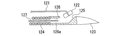
即ち、本実施形態の医療用処置具120は、図20に示すように、上記縫合糸121の先端に接続された抜け止めチップ(抜止部材)122と、該抜け止めチップ122を着脱自在に収納すると共に、先端に生体組織に穿刺する針部123を有する縫合針本体124とを備えている。
Next, a sixth embodiment of the medical treatment tool according to the present invention will be described below with reference to FIGS. In the sixth embodiment, the same components as those in the first embodiment are denoted by the same reference numerals, and the description thereof is omitted.
The difference between the sixth embodiment and the first embodiment is that in the first embodiment, the medical treatment tool is a ligation device for ligating a lesioned part of a living tissue and the wire is a
That is, as shown in FIG. 20, the
上記縫合針本体124は、密巻きコイルによってパイプ状に形成されたものであり、処置具チャンネル4内で湾曲できるように可撓性を有している。また、縫合針本体124の先端には、上記針部123が取り付けられている。該針部123は、ステンレス等の金属部材により、先端を尖鋭な細長形状に形成されると共に、外径が縫合針本体124と同一になるように形成されている。また、針部123には、側面に開口部125が形成されている。この開口部125には、縫合針本体124の内孔124aと連通する収納部126が形成され、上記抜け止めチップ122を収納できるようになっている。
The suturing needle
上記抜け止めチップ122は、円柱状に形成されており、中間部の窪み122aに上記縫合糸121の先端が縛りつけられている。該抜け止めチップ122は、軸方向を縫合針本体124の軸方向と一致させて収納部126内に収納されている。また、収納部126内には、抜け止めチップ122の端部に嵌合する嵌合孔126aが形成されており、抜け止めチップ122の端部を嵌合孔126aに嵌合するように、収納させることで容易に収納部126から脱落しないようになっている。
また、縫合針本体124の内孔124a内には、収納部126内に収納されている抜け止めチップ122を該収納部126から押し出す可撓性を有する押し出しワイヤ127が進退自在に配されている。該押し出しワイヤ127は、手元操作部63で進退操作できるようになっている。
また、縫合糸121は、抜け止めチップ122からストッパ80及びワイヤ保持部材51を通って係合部材66aに係合されている。
The
Further, in the
The
また、本実施形態においては、外側シース65は、切断用シース53及び縫合針本体124を覆うようになっている。つまり、縫合針本体124は、外側シース65内にて切断用シース53とは別に進退自在となるように構成されている。また、該縫合針本体124
の操作も、手元操作部63で操作できるようになっている。
更に、側孔57、ワイヤ保持部材51の先端側孔51c及び基端側孔51dは、一対ではなく、それぞれ1つずつ形成されている。
In the present embodiment, the
This operation can also be performed by the
Further, the
このように構成された医療用処置具120により、病変部を縫合する場合について以下に説明する。
まず、医師は、モニタ39に表示される内視鏡画像により、内視鏡挿入部10の先端が縫合を行う病変部に達したことを判断すると、モニタ39を見ながら内視鏡挿入部10の先端を病変部の近傍に位置させる。次に、医師は、この状態で、医療用処置具120を処置具挿入孔15より処置具チャンネル4内に挿入する。この際、医師は、グリップ72を先端方向に移動させて、図20に示すように、外側シース65を切断用シース53及び縫合針本体124の周囲に覆うように被せた状態で処置具チャンネル4内に挿入する。
A case where a lesion is sutured with the
First, when the doctor determines from the endoscopic image displayed on the
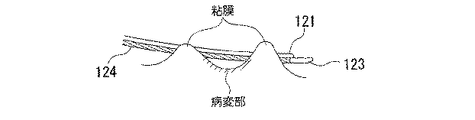
そして、医師は、モニタ39に表示される内視鏡画像により、内視鏡挿入部10の先端面より外側シース65が突出したことを確認後、グリップ72を基端方向に移動させて、外側シース65を後退させる。そして、医師は、モニタ39を見ながら縫合針本体124を操作して、図21に示すように、止血しようとする病変部手間の粘膜に針部123を穿刺すると共に、病変部を挟んだ反対側の粘膜にも穿刺して、針部123を貫通させる。
なお、この際、縫合糸121は、縫合針本体124の動きを規制しないように、十分長い長さとされている。
Then, after confirming that the
At this time, the
この状態において、図22に示すように、押し出しワイヤ127を先端方向に押し出して、抜け止めチップ122を嵌合孔126aから外して、収納部126から押し出す。これにより、抜け止めチップ122は、縫合針本体124から離脱した状態となる。抜け止めチップ122の離脱後、縫合針本体124の引き抜き操作を行うことで、図23に示すように、抜け止めチップ122が生体組織に引っ掛かった状態となると共に、該抜け止めチップ122に接続された縫合糸121が針部123によって穿刺された両粘膜を貫通した状態となる。
In this state, as shown in FIG. 22, the push-
次に、この状態でスライダ71を基端方向に操作して、操作ワイヤ66aを引っ張ることで、図24に示すように、穿刺した粘膜部分を引き寄せる。即ち、縫合糸121が、貫通した両粘膜部分を寄せ合わして出血部である病変部を閉じる。そして、ストッパ80を粘膜部分に当接させた状態で、病変部を閉じる。その後、切断グリップ54を基端方向に移動させて切断用シース53を引っ張り操作することで、側孔57と基端側孔51dとの間で縫合糸121を挟持しながら確実に刃部57aによって切断することができる。縫合糸121の切断後、図25に示すように、病変部が閉じた状態で縫合され、ストッパ80によって確実に固定される。これにより、病変部の縫合処置が終了する。
Next, in this state, the
なお、本発明の技術範囲は上記実施の形態に限定されるものではなく、本発明の趣旨を逸脱しない範囲において種々の変更を加えることが可能である。
例えば、第1実施形態において、側孔をワイヤ保持部材の基端側孔の先端側に配し、該側孔と基端側孔との間で結紮ワイヤを切断したが、これに限られず、第5実施形態のように、側孔を先端側孔より先端側に配して、該側孔と先端側孔との間で結紮ワイヤを切断にしても構わない。こうすることで、切断後の結紮ワイヤを短くすることができるので、よりこの好ましい。
また、上記各実施形態においては、側孔に刃部を設けたが、これに限られず、第1の切断用部、即ち、ワイヤ保持部材の先端側孔又は基端側孔に刃部を設けても構わない。つまり、どちらか一方に刃部を設け、側孔との間で結紮ワイヤを挟持しながら切断できれば構わない。
また、本実施形態の医療用処置具を上記第6実施形態における縫合装置に適用した場合にも、上記第2実施形態から第5実施形態の構成を適用しても構わない。
The technical scope of the present invention is not limited to the above embodiment, and various modifications can be made without departing from the spirit of the present invention.
For example, in the first embodiment, the side hole is disposed on the distal end side of the proximal end side hole of the wire holding member, and the ligature wire is cut between the side hole and the proximal end side hole. As in the fifth embodiment, the side hole may be arranged on the tip side from the tip side hole, and the ligature wire may be cut between the side hole and the tip side hole. By carrying out like this, since the ligation wire after a cutting | disconnection can be shortened, this is more preferable.
In each of the above embodiments, the blade is provided in the side hole. However, the present invention is not limited to this, and the blade is provided in the first cutting portion, that is, the distal end side hole or the proximal end side hole of the wire holding member. It doesn't matter. That is, it suffices if the blade portion is provided on one of the sides and can be cut while holding the ligature wire between the side holes.
In addition, when the medical treatment tool of the present embodiment is applied to the suturing device in the sixth embodiment, the configurations of the second to fifth embodiments may be applied.
1、90、100、110、120 医療用処置具
50 結紮ワイヤ(線材)
51 ワイヤ保持部材(線材保持部材)
51c 先端側孔(先端案内部)
51d 基端側孔(基端案内部)
52 内側シース(第1のシース)
53 切断用シース(第2のシース)
54 切断グリップ(操作部)
55 切断手段
56 第1の切断用部
57 側孔(第2の切断用部)
57a 刃部
91 スリット
95 補強ワイヤ
101 切断部材(切断用部材)
121 縫合糸(線材)
122 抜け止めチップ(抜止部材)
123 針部
124 縫合針本体
1, 90, 100, 110, 120 Medical treatment instrument
50 Ligating wire (wire)
51 Wire holding member (wire holding member)
51c Tip side hole (tip guide)
51d Base end side hole (base end guide)
52 Inner sheath (first sheath)
53 Cutting sheath (second sheath)
54 Cutting grip (operation part)
55 cutting means 56 first cutting
121 Suture (wire)
122 Retaining tip (Retaining member)
123
Claims (8)
該線材を覆って進退自在に設けられ、該線材を保持する線材保持部材と、
該線材保持部材の基端側に当接して設けられた可撓性の第1のシースと、
該第1のシースを覆って、第1のシース及び前記線材保持部材に対して進退自在に設けられた可撓性の第2のシースと、
該第2のシースの基端側に接続され、第2のシースの進退操作を行う操作部と、
前記線材を切断する切断手段とを備え、
該切断手段が、前記線材保持部材に設けられた第1の切断用部と、前記第2のシースの先端に設けられて第1の切断用部より先端側に配されると共に該第1の切断用部との間で前記線材を挟持する第2の切断用部とを備え、第1の切断用部及び第2の切断用部の少なくとも一方が刃部であることを特徴とする医療用処置具。 A flexible wire that performs a predetermined treatment on a living tissue;
A wire holding member that covers the wire and is provided so as to freely advance and retract, and holds the wire;
A flexible first sheath provided in contact with the proximal end side of the wire holding member;
A flexible second sheath that covers the first sheath and is provided so as to be movable forward and backward with respect to the first sheath and the wire holding member;
An operation unit connected to a proximal end side of the second sheath and performing an advance / retreat operation of the second sheath;
Cutting means for cutting the wire,
The cutting means is provided at the distal end side of the first cutting portion and provided at the distal end of the first cutting portion provided on the wire holding member and the second sheath, and the first cutting portion. And a second cutting part for sandwiching the wire between the cutting part and at least one of the first cutting part and the second cutting part is a blade part. Treatment tool.
前記第1の切断用部が、前記線材を前記線材保持部材の内部から外部に導く先端案内部と、該先端案内部より外部に導かれた線材を再度内部に導く基端案内部とを有し、
前記第2の切断用部が、前記先端案内部又は前記基端案内部との間で外部に露出した前記線材を挟持する位置に配されることを特徴とする医療用処置具。 The medical treatment tool according to claim 1, wherein
The first cutting portion has a distal end guide portion that guides the wire from the inside of the wire holding member to the outside, and a proximal end guide portion that guides the wire guided outside from the distal end guide portion to the inside again. And
The medical treatment instrument, wherein the second cutting part is disposed at a position where the wire rod exposed to the outside is sandwiched between the distal guide part or the proximal guide part.
前記第2のシースの先端には、先端側に開口部を有すると共に、前記第2の切断用部に接続されて前記線材を挿通可能なスリットが形成されていることを特徴とする医療用処置具。 The medical treatment tool according to claim 2,
A medical treatment characterized in that the distal end of the second sheath has an opening on the distal end side and is formed with a slit that is connected to the second cutting portion and through which the wire can be inserted. Ingredients.
前記第2の切断用部が、第2のシースに着脱自在な切断用部材に設けられていることを特徴とする医療用処置具。 The medical treatment tool according to claim 2,
The medical treatment instrument, wherein the second cutting part is provided on a cutting member that is detachable from the second sheath.
前記第1のシースが、コイルシースであることを特徴とする医療用処置具。 The medical treatment tool according to any one of claims 1 to 4,
The medical treatment instrument, wherein the first sheath is a coil sheath.
前記第2のシースには、前記第2の切断用部及び前記操作部に接続された補強ワイヤが該第2のシースの軸方向に沿って固定されていることを特徴とする医療用処置具。 The medical treatment tool according to any one of claims 1 to 5,
A medical treatment instrument, wherein a reinforcing wire connected to the second cutting section and the operation section is fixed to the second sheath along the axial direction of the second sheath. .
前記線材が、生体組織を結紮する結紮ワイヤであることを特徴とする医療用処置具。 The medical treatment tool according to any one of claims 1 to 6,
A medical treatment instrument, wherein the wire is a ligation wire for ligating a living tissue.
前記線材が、生体組織を縫合する縫合糸であり、
該縫合糸の先端に接続された抜止部材と、
該抜止部材を着脱自在に収納すると共に、先端に生体組織に穿刺する針部を有する縫合針本体とを備えることを特徴とする医療用処置具。 The medical treatment tool according to any one of claims 1 to 6,
The wire is a suture for suturing a living tissue;
A retaining member connected to the distal end of the suture;
A medical treatment instrument comprising a suture needle main body having a needle portion for puncturing a living tissue at a distal end while detachably storing the retaining member.
Priority Applications (4)
| Application Number | Priority Date | Filing Date | Title |
|---|---|---|---|
| JP2003349571A JP4358589B2 (en) | 2003-10-08 | 2003-10-08 | Medical treatment tool |
| EP04792250A EP1685802A4 (en) | 2003-10-08 | 2004-10-05 | Medical treatment instrument |
| PCT/JP2004/015000 WO2005034769A1 (en) | 2003-10-08 | 2004-10-05 | Medical treatment instrument |
| US11/399,664 US8206407B2 (en) | 2003-10-08 | 2006-04-06 | Medical procedure tool |
Applications Claiming Priority (1)
| Application Number | Priority Date | Filing Date | Title |
|---|---|---|---|
| JP2003349571A JP4358589B2 (en) | 2003-10-08 | 2003-10-08 | Medical treatment tool |
Publications (2)
| Publication Number | Publication Date |
|---|---|
| JP2005110983A JP2005110983A (en) | 2005-04-28 |
| JP4358589B2 true JP4358589B2 (en) | 2009-11-04 |
Family
ID=34431010
Family Applications (1)
| Application Number | Title | Priority Date | Filing Date |
|---|---|---|---|
| JP2003349571A Expired - Fee Related JP4358589B2 (en) | 2003-10-08 | 2003-10-08 | Medical treatment tool |
Country Status (4)
| Country | Link |
|---|---|
| US (1) | US8206407B2 (en) |
| EP (1) | EP1685802A4 (en) |
| JP (1) | JP4358589B2 (en) |
| WO (1) | WO2005034769A1 (en) |
Families Citing this family (50)
| Publication number | Priority date | Publication date | Assignee | Title |
|---|---|---|---|---|
| JP4700384B2 (en) | 2004-04-07 | 2011-06-15 | オリンパス株式会社 | Medical ligature suturing apparatus and medical ligature suturing system |
| JP4643328B2 (en) | 2004-04-07 | 2011-03-02 | オリンパス株式会社 | Medical ligature suturing device |
| JP4716745B2 (en) | 2005-02-04 | 2011-07-06 | オリンパス株式会社 | Medical suture ligation apparatus and medical suture ligation tool |
| US8128640B2 (en) | 2005-02-07 | 2012-03-06 | Ivy Sports Medicine LLC | System and method for all-inside suture fixation for implant attachment and soft tissue repair |
| US8808309B2 (en) | 2005-02-07 | 2014-08-19 | Ivy Sports Medicine, Llc | System and method for all-inside suture fixation for implant attachment and soft tissue repair |
| JP4823620B2 (en) * | 2005-05-24 | 2011-11-24 | オリンパス株式会社 | Medical suture ligation device |
| US8267942B2 (en) * | 2005-12-23 | 2012-09-18 | Ethicon, Inc. | Systems and methods for closing a vessel wound |
| US8105355B2 (en) | 2006-05-18 | 2012-01-31 | C.R. Bard, Inc. | Suture lock fastening device |
| EP2142107B8 (en) * | 2007-03-30 | 2013-02-20 | Sentreheart, Inc. | Devices and systems for closing the left atrial appendage |
| US9370341B2 (en) | 2008-10-23 | 2016-06-21 | Covidien Lp | Surgical retrieval apparatus |
| US8317827B2 (en) * | 2009-01-07 | 2012-11-27 | Ethicon Endo-Surgery, Inc. | Suturing devices and methods |
| US8585712B2 (en) | 2010-02-03 | 2013-11-19 | Covidien Lp | Surgical retrieval apparatus |
| US8540735B2 (en) | 2010-12-16 | 2013-09-24 | Apollo Endosurgery, Inc. | Endoscopic suture cinch system |
| US8579914B2 (en) | 2010-12-17 | 2013-11-12 | Covidien Lp | Specimen retrieval device |
| US8795291B2 (en) | 2011-04-29 | 2014-08-05 | Covidien Lp | Specimen retrieval device |
| US9993229B2 (en) * | 2011-11-08 | 2018-06-12 | Covidien Lp | Specimen retrieval device |
| US8961594B2 (en) * | 2012-05-31 | 2015-02-24 | 4Tech Inc. | Heart valve repair system |
| JP6430411B2 (en) | 2013-03-01 | 2018-11-28 | コヴィディエン リミテッド パートナーシップ | Sample collection device with pouch stop |
| WO2014164955A2 (en) | 2013-03-12 | 2014-10-09 | Apollo Endosurgery, Inc. | Endoscopic suture cinch system with replaceable cinch |
| US10448946B2 (en) | 2013-03-12 | 2019-10-22 | Apollo Endosurgery Us, Inc. | Endoscopic suture cinch |
| EP3000406A1 (en) * | 2013-03-14 | 2016-03-30 | Incumedx Inc. | Implants and methods of manufacturing the same |
| US9592067B2 (en) | 2013-06-14 | 2017-03-14 | Covidien Lp | Specimen retrieval device including a reusable shaft with interchangeable pouch |
| US9987031B2 (en) | 2013-06-14 | 2018-06-05 | Covidien Lp | Specimen retrieval device including an integrated sliding grasper |
| US9622750B2 (en) | 2013-08-21 | 2017-04-18 | Crh Medical Corporation | Elastic band ligation device with locking mechanism and method for treatment of hemorrhoids |
| US20150057680A1 (en) * | 2013-08-21 | 2015-02-26 | Crh Medical Corporation | Elastic band ligation device with anti-pinch feature and method for treatment of hemorrhoids |
| US9101360B2 (en) * | 2013-08-21 | 2015-08-11 | Crh Medical Corporation | Elastic band ligation device with integrated obturator and method for treatment of hemorrhoids |
| WO2015027166A2 (en) | 2013-08-23 | 2015-02-26 | Covidien Lp | Specimen retrieval device |
| US10022114B2 (en) | 2013-10-30 | 2018-07-17 | 4Tech Inc. | Percutaneous tether locking |
| JP6595232B2 (en) | 2015-07-02 | 2019-10-23 | ソニー・オリンパスメディカルソリューションズ株式会社 | Endoscope imaging apparatus, endoscope apparatus, and endoscope cable |
| US11090055B2 (en) | 2015-10-30 | 2021-08-17 | Incumedx Inc. | Devices and methods for delivering an implant to a vascular disorder |
| US10052108B2 (en) * | 2015-10-30 | 2018-08-21 | Incumedx, Inc. | Devices and methods for delivering an implant to a vascular disorder |
| US10932769B2 (en) | 2016-05-26 | 2021-03-02 | Ivy Sports Medicine, Llc | System and method for all-inside suture fixation for implant attachment and soft tissue repair |
| WO2018057963A1 (en) | 2016-09-23 | 2018-03-29 | Sentreheart, Inc. | Devices and methods for left atrial appendage closure |
| US10653400B2 (en) | 2017-08-07 | 2020-05-19 | Covidien Lp | Specimen retrieval device |
| US11065051B2 (en) | 2017-11-03 | 2021-07-20 | Covidien Lp | Specimen retrieval device |
| US10973543B2 (en) | 2018-01-10 | 2021-04-13 | Covidien Lp | Dual wall tissue extraction bag |
| US10874386B2 (en) | 2018-01-24 | 2020-12-29 | Covidien Lp | Specimen retrieval device |
| US11730459B2 (en) | 2018-02-22 | 2023-08-22 | Covidien Lp | Specimen retrieval devices and methods |
| JP2021519143A (en) | 2018-03-27 | 2021-08-10 | センターハート・インコーポレイテッドSentreHEART, Inc. | Devices and methods for left atrial appendage closure |
| US11083443B2 (en) | 2018-04-24 | 2021-08-10 | Covidien Lp | Specimen retrieval device |
| US11045176B2 (en) | 2018-05-18 | 2021-06-29 | Covidien Lp | Specimen retrieval device |
| US11134932B2 (en) | 2018-08-13 | 2021-10-05 | Covidien Lp | Specimen retrieval device |
| US11730480B2 (en) | 2018-09-14 | 2023-08-22 | Covidien Lp | Method and apparatus for accessing matter disposed within an internal body vessel |
| CN109124717B (en) * | 2018-09-17 | 2023-07-18 | 湖南灵康医疗科技有限公司 | Elastic thread ligation device with thread cutting device and elastic thread setting method |
| US11191559B2 (en) | 2018-09-19 | 2021-12-07 | Covidien Lp | Specimen retrieval device |
| US11344300B2 (en) | 2019-03-26 | 2022-05-31 | Covidien Lp | Specimen capture stapler |
| US11172915B2 (en) | 2019-04-24 | 2021-11-16 | Covidien Lp | Specimen retrieval devices with selective bag release |
| US11246578B2 (en) | 2019-05-15 | 2022-02-15 | Covidien Lp | Tissue collection bags with inner surface pouches |
| US11426151B2 (en) | 2019-06-04 | 2022-08-30 | Covidien Lp | Bag closure for specimen retrieval device |
| US11446015B2 (en) | 2019-10-30 | 2022-09-20 | Covidien Lp | Specimen retrieval bag |
Family Cites Families (13)
| Publication number | Priority date | Publication date | Assignee | Title |
|---|---|---|---|---|
| US1625602A (en) * | 1926-04-06 | 1927-04-19 | Harold G Gould | Surgical appliance |
| JPS524114B2 (en) * | 1971-12-27 | 1977-02-01 | ||
| JPS5430692A (en) * | 1977-08-12 | 1979-03-07 | Fuji Photo Optical Co Ltd | Device for ligating endoscope |
| US5176691A (en) * | 1990-09-11 | 1993-01-05 | Pierce Instruments, Inc. | Knot pusher |
| US5242459A (en) * | 1992-07-10 | 1993-09-07 | Laparomed Corporation | Device and method for applying a ligating loop |
| US5693059A (en) | 1995-09-15 | 1997-12-02 | Yoon; Inbae | Ligating instrument with multiple loop ligature supply and methods therefor |
| JP2001000440A (en) * | 1999-06-17 | 2001-01-09 | Asahi Optical Co Ltd | Clipping tool for endoscope |
| US6602263B1 (en) * | 1999-11-30 | 2003-08-05 | St. Jude Medical Atg, Inc. | Medical grafting methods and apparatus |
| US7220266B2 (en) | 2000-05-19 | 2007-05-22 | C. R. Bard, Inc. | Tissue capturing and suturing device and method |
| US6554845B1 (en) * | 2000-09-15 | 2003-04-29 | PARÉ Surgical, Inc. | Suturing apparatus and method |
| JP4727074B2 (en) * | 2001-07-09 | 2011-07-20 | オリンパス株式会社 | Endoscopic treatment tool |
| US7918867B2 (en) * | 2001-12-07 | 2011-04-05 | Abbott Laboratories | Suture trimmer |
| JP2003204966A (en) * | 2002-01-16 | 2003-07-22 | Olympus Optical Co Ltd | Medical ligation unit |
-
2003
- 2003-10-08 JP JP2003349571A patent/JP4358589B2/en not_active Expired - Fee Related
-
2004
- 2004-10-05 WO PCT/JP2004/015000 patent/WO2005034769A1/en active Application Filing
- 2004-10-05 EP EP04792250A patent/EP1685802A4/en not_active Ceased
-
2006
- 2006-04-06 US US11/399,664 patent/US8206407B2/en active Active
Also Published As
| Publication number | Publication date |
|---|---|
| WO2005034769A1 (en) | 2005-04-21 |
| EP1685802A4 (en) | 2012-10-31 |
| US8206407B2 (en) | 2012-06-26 |
| US20060259044A1 (en) | 2006-11-16 |
| JP2005110983A (en) | 2005-04-28 |
| EP1685802A1 (en) | 2006-08-02 |
Similar Documents
| Publication | Publication Date | Title |
|---|---|---|
| JP4358589B2 (en) | Medical treatment tool | |
| US8118819B2 (en) | Medical treatment tool | |
| JP4405158B2 (en) | Endoscopic treatment tool | |
| JP4823533B2 (en) | Medical suture ligation tool and medical suture ligation apparatus | |
| US8758375B2 (en) | Method for suturing perforation | |
| JP4643328B2 (en) | Medical ligature suturing device | |
| US8298249B2 (en) | Medical ligating apparatus | |
| US20090005792A1 (en) | Medical Suturing and Ligating Apparatus | |
| JP4533858B2 (en) | Ligation device | |
| WO2018173474A1 (en) | Surgical clipping tool | |
| US20130317291A1 (en) | Treatment system and endoscope system | |
| JP2007075613A (en) | Treatment appliance cartridge for biological tissue | |
| WO2015087939A1 (en) | Endoscope treatment instrument | |
| JPH10286224A (en) | Endoscope for ligation treatment | |
| WO2017111163A1 (en) | Endoscopic suture ligation tool | |
| JP2006212241A (en) | Medical suture ligation device and medical suture ligation apparatus | |
| US11045078B2 (en) | Treatment instrument insertion tool | |
| US20230110619A1 (en) | Endoscopic suture cinch | |
| JP2006081726A (en) | Treatment instrument for endoscope and treatment unit for use in treatment instrument for endoscope | |
| JP2006000676A (en) | Thread-clamping implement for fitting thread for suturing | |
| JP2010082284A (en) | Suture system, suture device, and suture method | |
| JP4500297B2 (en) | Medical ligature |
Legal Events
| Date | Code | Title | Description |
|---|---|---|---|
| A621 | Written request for application examination |
Free format text: JAPANESE INTERMEDIATE CODE: A621 Effective date: 20060831 |
|
| TRDD | Decision of grant or rejection written | ||
| A01 | Written decision to grant a patent or to grant a registration (utility model) |
Free format text: JAPANESE INTERMEDIATE CODE: A01 Effective date: 20090714 |
|
| A01 | Written decision to grant a patent or to grant a registration (utility model) |
Free format text: JAPANESE INTERMEDIATE CODE: A01 |
|
| A61 | First payment of annual fees (during grant procedure) |
Free format text: JAPANESE INTERMEDIATE CODE: A61 Effective date: 20090806 |
|
| FPAY | Renewal fee payment (event date is renewal date of database) |
Free format text: PAYMENT UNTIL: 20120814 Year of fee payment: 3 |
|
| R151 | Written notification of patent or utility model registration |
Ref document number: 4358589 Country of ref document: JP Free format text: JAPANESE INTERMEDIATE CODE: R151 |
|
| FPAY | Renewal fee payment (event date is renewal date of database) |
Free format text: PAYMENT UNTIL: 20120814 Year of fee payment: 3 |
|
| FPAY | Renewal fee payment (event date is renewal date of database) |
Free format text: PAYMENT UNTIL: 20130814 Year of fee payment: 4 |
|
| S531 | Written request for registration of change of domicile |
Free format text: JAPANESE INTERMEDIATE CODE: R313531 |
|
| R350 | Written notification of registration of transfer |
Free format text: JAPANESE INTERMEDIATE CODE: R350 |
|
| R250 | Receipt of annual fees |
Free format text: JAPANESE INTERMEDIATE CODE: R250 |
|
| LAPS | Cancellation because of no payment of annual fees |