JP4358271B2 - Subcarrier allocation method and apparatus in broadband wireless communication system using multiple carriers - Google Patents
Subcarrier allocation method and apparatus in broadband wireless communication system using multiple carriers Download PDFInfo
- Publication number
- JP4358271B2 JP4358271B2 JP2007501723A JP2007501723A JP4358271B2 JP 4358271 B2 JP4358271 B2 JP 4358271B2 JP 2007501723 A JP2007501723 A JP 2007501723A JP 2007501723 A JP2007501723 A JP 2007501723A JP 4358271 B2 JP4358271 B2 JP 4358271B2
- Authority
- JP
- Japan
- Prior art keywords
- subcarrier
- index
- here
- sequence
- subcarriers
- Prior art date
- Legal status (The legal status is an assumption and is not a legal conclusion. Google has not performed a legal analysis and makes no representation as to the accuracy of the status listed.)
- Expired - Fee Related
Links
- 238000000034 method Methods 0.000 title claims description 46
- 238000004891 communication Methods 0.000 title claims description 26
- 239000000969 carrier Substances 0.000 title claims description 12
- 230000032823 cell division Effects 0.000 claims description 29
- 230000007704 transition Effects 0.000 claims description 9
- 230000003247 decreasing effect Effects 0.000 claims description 5
- 238000005192 partition Methods 0.000 claims description 4
- 238000010586 diagram Methods 0.000 description 8
- 238000012546 transfer Methods 0.000 description 7
- 230000005540 biological transmission Effects 0.000 description 2
- 238000006243 chemical reaction Methods 0.000 description 2
- 238000007796 conventional method Methods 0.000 description 2
- 238000012937 correction Methods 0.000 description 2
- 125000004122 cyclic group Chemical group 0.000 description 2
- 238000005516 engineering process Methods 0.000 description 2
- 238000009434 installation Methods 0.000 description 2
- 238000012545 processing Methods 0.000 description 2
- 238000012790 confirmation Methods 0.000 description 1
- 238000011161 development Methods 0.000 description 1
- 230000000694 effects Effects 0.000 description 1
- 238000005562 fading Methods 0.000 description 1
- 238000012966 insertion method Methods 0.000 description 1
- 230000010363 phase shift Effects 0.000 description 1
- 238000013468 resource allocation Methods 0.000 description 1
Images

Classifications
-
- H—ELECTRICITY
- H05—ELECTRIC TECHNIQUES NOT OTHERWISE PROVIDED FOR
- H05B—ELECTRIC HEATING; ELECTRIC LIGHT SOURCES NOT OTHERWISE PROVIDED FOR; CIRCUIT ARRANGEMENTS FOR ELECTRIC LIGHT SOURCES, IN GENERAL
- H05B3/00—Ohmic-resistance heating
- H05B3/10—Heating elements characterised by the composition or nature of the materials or by the arrangement of the conductor
- H05B3/12—Heating elements characterised by the composition or nature of the materials or by the arrangement of the conductor characterised by the composition or nature of the conductive material
- H05B3/14—Heating elements characterised by the composition or nature of the materials or by the arrangement of the conductor characterised by the composition or nature of the conductive material the material being non-metallic
- H05B3/145—Carbon only, e.g. carbon black, graphite
-
- H—ELECTRICITY
- H04—ELECTRIC COMMUNICATION TECHNIQUE
- H04L—TRANSMISSION OF DIGITAL INFORMATION, e.g. TELEGRAPHIC COMMUNICATION
- H04L5/00—Arrangements affording multiple use of the transmission path
- H04L5/02—Channels characterised by the type of signal
- H04L5/023—Multiplexing of multicarrier modulation signals
-
- D—TEXTILES; PAPER
- D06—TREATMENT OF TEXTILES OR THE LIKE; LAUNDERING; FLEXIBLE MATERIALS NOT OTHERWISE PROVIDED FOR
- D06F—LAUNDERING, DRYING, IRONING, PRESSING OR FOLDING TEXTILE ARTICLES
- D06F58/00—Domestic laundry dryers
- D06F58/16—Domestic laundry dryers having heatable surfaces for contacting the laundry
-
- H—ELECTRICITY
- H05—ELECTRIC TECHNIQUES NOT OTHERWISE PROVIDED FOR
- H05B—ELECTRIC HEATING; ELECTRIC LIGHT SOURCES NOT OTHERWISE PROVIDED FOR; CIRCUIT ARRANGEMENTS FOR ELECTRIC LIGHT SOURCES, IN GENERAL
- H05B1/00—Details of electric heating devices
- H05B1/02—Automatic switching arrangements specially adapted to apparatus ; Control of heating devices
- H05B1/0202—Switches
-
- H—ELECTRICITY
- H05—ELECTRIC TECHNIQUES NOT OTHERWISE PROVIDED FOR
- H05B—ELECTRIC HEATING; ELECTRIC LIGHT SOURCES NOT OTHERWISE PROVIDED FOR; CIRCUIT ARRANGEMENTS FOR ELECTRIC LIGHT SOURCES, IN GENERAL
- H05B3/00—Ohmic-resistance heating
- H05B3/20—Heating elements having extended surface area substantially in a two-dimensional plane, e.g. plate-heater
- H05B3/22—Heating elements having extended surface area substantially in a two-dimensional plane, e.g. plate-heater non-flexible
-
- H—ELECTRICITY
- H04—ELECTRIC COMMUNICATION TECHNIQUE
- H04L—TRANSMISSION OF DIGITAL INFORMATION, e.g. TELEGRAPHIC COMMUNICATION
- H04L5/00—Arrangements affording multiple use of the transmission path
- H04L5/003—Arrangements for allocating sub-channels of the transmission path
- H04L5/0044—Arrangements for allocating sub-channels of the transmission path allocation of payload
-
- H—ELECTRICITY
- H04—ELECTRIC COMMUNICATION TECHNIQUE
- H04W—WIRELESS COMMUNICATION NETWORKS
- H04W72/00—Local resource management
- H04W72/04—Wireless resource allocation
-
- H—ELECTRICITY
- H05—ELECTRIC TECHNIQUES NOT OTHERWISE PROVIDED FOR
- H05B—ELECTRIC HEATING; ELECTRIC LIGHT SOURCES NOT OTHERWISE PROVIDED FOR; CIRCUIT ARRANGEMENTS FOR ELECTRIC LIGHT SOURCES, IN GENERAL
- H05B2203/00—Aspects relating to Ohmic resistive heating covered by group H05B3/00
- H05B2203/02—Heaters using heating elements having a positive temperature coefficient
Landscapes
- Engineering & Computer Science (AREA)
- Signal Processing (AREA)
- Computer Networks & Wireless Communication (AREA)
- Textile Engineering (AREA)
- Mobile Radio Communication Systems (AREA)
- Error Detection And Correction (AREA)
Description
本発明は、広帯域無線通信システムの通信資源割り当て方法に係り、特に、多重搬送波(Multi Carrier)を用いる広帯域無線通信システムにおける副搬送波(Sub-carrier)割り当て方法及び装置に関する。 The present invention relates to a communication resource allocation method for a broadband wireless communication system, and more particularly, to a sub-carrier allocation method and apparatus in a broadband wireless communication system using multiple carriers.
多重搬送波変調(Multi-Carrier Modulation)方式が初めて適用されたのは、1950年代後半の軍用ラジオで、以降、複数の直交する副搬送波を重畳させる代表的な多重搬送波転送方式である直交周波数分割多重(Orthogonal Frequency Division Multiplexing:以下、“OFDM”と称する。)方式が、1970年代から発展し始まった。OFDM方式は、直列に入力されるシンボル(Symbol)を並列変換した後、これらをそれぞれ、相互直交性を有する複数の副搬送波を通じて変調し転送する方式であるが、多重搬送波間の直交変調実現の困難から実際システム適用には限界があった。 Multi-Carrier Modulation was first applied to military radios in the late 1950s, and since then, orthogonal frequency division multiplexing, which is a typical multi-carrier transmission method that superimposes multiple orthogonal subcarriers. (Orthogonal Frequency Division Multiplexing: hereinafter referred to as “OFDM”) has been developed since the 1970s. The OFDM system is a system in which symbols (Symbols) input in series are converted in parallel and then modulated and transferred through a plurality of sub-carriers having mutual orthogonality. Due to difficulties, there was a limit to practical system application.
しかしながら、1971年Weinstein等が、DFT(Discrete Fourier Transform)を用いてOFDM方式の変復調が效率的に処理可能であるということを発表し、保護区間(Guard Interval)の使用と挿入方式が知られながら多重経路及び遅延拡散に対するシステムの否定的影響がより減少し、また、ハードウェア的な複雑度(Complexity)を解決する高速フーリエ変換(Fast Fourier Transform:FFT)と逆高速フーリエ変換(Inverse Fast Fourier Transform:IFFT)を含む各種デジタル信号処理技術が発展するに伴い、OFDM方式の実際適用の可能性も高くなった。 However, in 1971, Weinstein et al. Announced that OFDM modulation / demodulation can be efficiently processed using DFT (Discrete Fourier Transform), and the use of guard intervals and insertion methods are known. Fast Fourier Transform (FFT) and Inverse Fast Fourier Transform (FFT) solves hardware complexities with less negative system impact on multipath and delay spread With the development of various digital signal processing technologies including: IFFT), the possibility of actual application of the OFDM scheme has increased.
このようなOFDM方式は、デジタルオーディオ放送(Digital Audio Broadcasting:DAB)とデジタルテレビ、無線ラン(Wireless Local Area Network:WLAN)及び無線ATM(Wireless Asynchronous Transfer Mode)などのデジタル転送技術に広範囲に適用されることができ、周波数使用効率が良く、保護区間を用いてシンボル間干渉(ISI:Inter Symbol Interference)影響を減らすことができ、多重経路フェーディング(Multi-path fading)に強い特性から、高速データ転送時に最適の転送効率が得られるという特長がある。 Such an OFDM system is widely applied to digital transfer technologies such as digital audio broadcasting (DAB) and digital television, wireless LAN (Wireless Local Area Network: WLAN), and wireless ATM (Wireless Asynchronous Transfer Mode). High frequency use efficiency, and can reduce the effect of Inter Symbol Interference (ISI) by using the guard interval, and it has high resistance to multi-path fading. There is a feature that optimum transfer efficiency can be obtained during transfer.
そして、OFDM方式を基盤とする多重接続方式は、OFDMA(Orthogonal Frequency Division Multiplexing Access)方式とFH(Frequency Hopping)−OFDMとに大別される。FH−OFDM方式は、OFDM方式に周波数跳躍(Frequency Hopping)を結合したもので、OFDMA及びFH−OFDM方式の2技術とも、データトーン(Data Tone)を全体帯域に均一に分布させ、周波数ダイバーシティー(Diversity)利得を得ることを目標としている。OFDMA方式は、データ転送時に、それぞれのOFDMシンボル(Symbol)を、複数の副搬送波に分けて載せた後、複数の副搬送波を一つの副チャネル(Sub-channel)にまとめて転送する。 The multiple access schemes based on the OFDM scheme are roughly classified into an OFDMA (Orthogonal Frequency Division Multiplexing Access) scheme and FH (Frequency Hopping) -OFDM. The FH-OFDM scheme combines frequency hopping with the OFDM scheme, and both the OFDMA and FH-OFDM schemes distribute data tones (Data Tone) uniformly over the entire band, and frequency diversity. (Diversity) The goal is to gain. In the OFDMA scheme, at the time of data transfer, each OFDM symbol (Symbol) is divided into a plurality of subcarriers, and then the plurality of subcarriers are collectively transferred to one subchannel (Sub-channel).
そして、OFDMA方式を広帯域無線通信システムに適用した例が、周知のIEEE 802.16aまたは802.16eシステムである。このようなOFDMA方式は、例えば、2048個のFFTを使用し、1702個のトーン(Tone)を166個のパイロットトーン(Pilot Tone)と1536個のデータトーン(Data Tone)とに分けて使用し、1536個のデータトーン(Data Tone)を48個ずつまとめて32個の副チャネルに分けて各使用者に割り当てる。すなわち、OFDMA方式は、周波数領域を、複数の副搬送波からなる副チャネルに区分し、時間領域を複数のタイムスロットに区分した後、使用者別に副チャネルを割り当てる多重接続方式を意味する。 An example in which the OFDMA system is applied to a broadband wireless communication system is a well-known IEEE 802.16a or 802.16e system. In such an OFDMA scheme, for example, 2048 FFTs are used, and 1702 tones (Tone) are divided into 166 pilot tones (Pilot Tone) and 1536 data tones (Data Tone). , 1536 data tones (Data Tone) are collectively divided into 32 sub-channels and assigned to each user. That is, the OFDMA scheme means a multiple access scheme in which the frequency domain is divided into subchannels composed of a plurality of subcarriers, the time domain is divided into a plurality of time slots, and then subchannels are allocated to each user.
そして、OFDMA方式を基盤とし、例えば、10MHzの広帯域を周波数領域のみで副チャネル単位に分けて使用するIEEE 802.16aまたは802.16eシステムは、2048個のFFTを用いて各OFDMシンボル(Symbol)当たり約1600〜1700個の副搬送波を割り当てる。したがって、副搬送波の割り当て形態によってセル個数の増大が可能である。しかしながら、多重セル環境でチャネル間衝突特性を考慮し、従来の方式で副搬送波を割り当てて副チャネルを構成する場合、約40個のセル区分のみが可能である。広帯域無線網設置を容易にするには、セル区分数を100個程度に増加させる必要があり、よって、従来方式で副チャネル/副搬送波を割り当てるOFDMA方式は、セル個数の増設に限界があった。 An IEEE 802.16a or 802.16e system, which is based on the OFDMA system and uses a wide band of 10 MHz divided into subchannel units only in the frequency domain, for example, uses 2048 FFTs to represent each OFDM symbol. About 1600 to 1700 subcarriers are allocated. Therefore, the number of cells can be increased according to the subcarrier allocation form. However, when considering the collision characteristics between channels in a multi-cell environment and sub-carriers are configured by assigning sub-carriers according to the conventional method, only about 40 cell segments are possible. In order to facilitate the installation of a broadband wireless network, it is necessary to increase the number of cell divisions to about 100. Therefore, the OFDMA method in which subchannels / subcarriers are allocated in the conventional method has a limit in increasing the number of cells. .
本発明の目的は、多重搬送波を用いる広帯域無線通信システムのセル個数を増大させることができる副搬送波割り当て方法及び装置を提供することにある。 An object of the present invention is to provide a subcarrier allocation method and apparatus capable of increasing the number of cells in a broadband wireless communication system using multiple carriers.
本発明の他の目的は、多重搬送波を用いる広帯域無線通信システムの副チャネル間の衝突を減らす副搬送波割り当て方法及び装置を提供することにある。 It is another object of the present invention to provide a subcarrier allocation method and apparatus for reducing collisions between subchannels of a broadband wireless communication system using multiple carriers.
上記目的を達成するための本発明係る方法は、少なくとも一つの副チャネルを通じて端末と基地局が通信する無線通信システムにおいて複数の副搬送波を副チャネルに割り当てる副搬送波割り当て方法であって、一つのセルの副搬送波を、少なくとも一つの連続した副搬送波を含む複数の副搬送波グループに区分する過程と、セル識別情報、複数のリードソロモン数列、及び前記複数の副搬送波グループと関連した情報を用いて、各副搬送波グループから一つの副搬送波を選択するして前記複数の副搬送波を前記副チャネルに割り当てる過程と、を備えてなることを特徴とする。 In order to achieve the above object, a method according to the present invention is a subcarrier allocation method for allocating a plurality of subcarriers to a subchannel in a wireless communication system in which a terminal and a base station communicate through at least one subchannel. A plurality of subcarrier groups including at least one continuous subcarrier, cell identification information, a plurality of Reed-Solomon number sequences, and information related to the plurality of subcarrier groups, Selecting one subcarrier from each subcarrier group and allocating the plurality of subcarriers to the subchannel.
上記目的を達成するための本発明係る装置は、少なくとも一つの副チャネルを通じて端末と基地局が通信する無線通信システムにおいて、複数の副搬送波を副チャネルに割り当てる副搬送波割り当て装置であって、一つのセルの副搬送波を、少なくとも一つの連続した副搬送波を含む複数の副搬送波グループに区分する副搬送波グループ生成部と、セル識別情報と複数のリードソロモン数列を用いてセル区分のための数列を生成するセル区分部と、前記セル区分のための数列と前記複数の副搬送波グループと関連した情報を用いて、前記複数の副搬送波を前記副チャネルに割り当てる副搬送波割り当て部と、を備えてなることを特徴とする。 In order to achieve the above object, an apparatus according to the present invention is a subcarrier allocation apparatus for allocating a plurality of subcarriers to a subchannel in a wireless communication system in which a terminal and a base station communicate through at least one subchannel. A subcarrier group generation unit that divides a subcarrier of a cell into a plurality of subcarrier groups including at least one continuous subcarrier, and generates a sequence for cell division using cell identification information and a plurality of Reed-Solomon number sequences. And a subcarrier allocating unit that allocates the plurality of subcarriers to the subchannel using information related to the sequence for cell division and the plurality of subcarrier groups. It is characterized by.
本発明によれば、OFDMA方式を用いる通信システムにおいて、限定された副搬送波資源をもって、区分可能なセル数を自乗倍に増加させることが可能になる。また、区分可能なセル数を既存の個数に制限する場合、本発明のセル番号指定によれば、構造変更無しで、副チャネル間の衝突数を最大限でも1に抑えることが可能になる。 According to the present invention, in a communication system using the OFDMA scheme, the number of cells that can be classified can be increased by a square factor with limited subcarrier resources. When the number of cells that can be classified is limited to the existing number, according to the cell number designation of the present invention, the number of collisions between the subchannels can be suppressed to 1 at most without changing the structure.
以下、本発明に係る好ましい実施形態を、添付の図面を参照しつつ詳細に説明する。ただし、下記の説明では、本発明の要旨を不明瞭にする公知技術については適宜説明を省略するものとする。 Hereinafter, preferred embodiments of the present invention will be described in detail with reference to the accompanying drawings. However, in the following description, descriptions of known techniques that obscure the gist of the present invention will be omitted as appropriate.
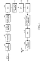
図1は、本発明が適用されるOFDMA通信システムの送信機構造を示すブロック図である。図1を参照すると、送信機は、転送誤り確認のためのCRC(Cyclic Redundancy Check)ビットを生成するCRC挿入器101、データビットを符号化するエンコーダ(Encoder)103、定められた変調方式でシンボル変調を行うシンボルマッピング器(Symbol Mapper)105、使用者別に副チャネルを割り当てるものの、後述する本発明のセル区分数列と副チャネル数列を用いて、区分可能なセル個数を最大化する副チャネル割り当て器(Sub-Channel Allocator)107と、を備える。
FIG. 1 is a block diagram showing a transmitter structure of an OFDMA communication system to which the present invention is applied. Referring to FIG. 1, a transmitter includes a
さらに、図1の送信機は、直列変調シンボルを受信して並列信号に変換する直列/並列変換器109、パイロット(Pilot)シンボル挿入器111、並列に入力される副チャネルの変調信号を逆高速フーリエ変換するIFFT(Inverse Fast Fourier Transform)変換器113と、並列変調信号を直列シンボル列に変換する並列/直列変換器115、直列シンボル列に保護区間を挿入する保護区間(Guard Interval)挿入器117、D/A(Digital/Analog)変換器119、及びRF(Radio Frequency)処理器(121)を備えて構成される。
Further, the transmitter of FIG. 1 receives a serial modulation symbol and converts it into a parallel signal, a serial /
図1の構成を有する送信機の動作について説明すると、転送する使用者データビット及び制御データビット(以下、“情報データビット”とまとめていう。)が発生すると、CRC挿入器101は、当該情報データビットにCRCビットを挿入し、エンコーダ103は、CRC挿入器101の出力信号を、あらかじめ設定された符号化方式によって符号化してシンボルマッピング器105に出力する。ここで、符号化方式には、所定の符号率(Code Rate)を有するターボ符号化(Turbo Coding)方式及び畳み込み符号化(Convolutional Coding)等がある。
The operation of the transmitter having the configuration of FIG. 1 will be described. When user data bits and control data bits to be transferred (hereinafter collectively referred to as “information data bits”) are generated, the
シンボルマッピング器105は、エンコーダ313から出力された符号化ビットを、あらかじめ設定された変調方式で変調シンボルに変調した後、副チャネル割り当て器107に出力する。ここで、変調方式には、周知のQPSK(Quadrature Phase Shift Keying)方式及び16QAM(Quadrature Amplitude Modulation)方式等がある。副チャネル割り当て器107は、シンボルマッピング器105から出力された変調シンボルに副チャネルを割り当てた後、直列/並列変換器109に出力する。
The
ここで、副チャネル割り当て器107の副チャネル割り当て動作は、本発明で提案するセル区分数列と副チャネル数列を用いて行い、本発明の副チャネル割り当て方式についての詳細な説明は後述する。直列/並列変換器109は、副チャネル割り当て器107から出力された、副チャネル及びバンド(band)が割り当てられた直列変調シンボルを並列信号に変換し、パイロットシンボル挿入器111は、直列/並列変換器109から受信した並列変調シンボルにパイロットシンボルを挿入する。
Here, the subchannel allocation operation of the
続いて、IFFT器113は、パイロットシンボル挿入器111の出力信号に対してN−ポイント(N-point)IFFTを行い、並列/直列変換器115は、IFFT器113の出力信号を直列信号に変換する。保護区間挿入器117は、並列/直列変換器115の並列信号に、所定の保護区間を挿入する。ここで、保護区間は、OFDMA通信システムでOFDMシンボル列を送信する時に、以前OFDMシンボル時間に送信された以前OFDMシンボルと、現在OFDMシンボル時間に送信される現在OFDMシンボル間の干渉を除去する役割を担う。
Subsequently, IFFT
D/A変換器119は、保護区間挿入器117の出力信号をアナログ信号に変換し、RF処理器121は、フィルター(filter)と前処理器(front end unit)などを備え、D/A変換器119の出力信号をエアー(air)上で転送可能なようにRF処理した後、送信アンテナ(Tx antenna)から無線網に送出する。
The D /
本発明による副チャネル割り当て方法は、図1の各構成要素のうち副チャネル割り当て器107の動作と関連するもので、本発明では、副チャネル割り当て器107で割り当て可能なセル個数を増大させうる副搬送波割り当て方案を提案する。
The subchannel allocating method according to the present invention relates to the operation of the
まず、本発明による副チャネル割り当て方法を説明するに先立ち、本発明が適用されるOFDMA通信システムのチャネル構造について簡略に説明する。 First, prior to describing the sub-channel allocation method according to the present invention, the channel structure of an OFDMA communication system to which the present invention is applied will be briefly described.
OFDMA通信システムは、並列送信データを、相互直交性を有する複数の副搬送波に分けて載せ転送する。この副搬送波は、データを転送するためのデータ副搬送波と、チャネル推定のためのパイロット副搬送波とを含み、複数の副搬送波が集まって1副チャネルを構成する。1副チャネルは、1名の加入者を収容するための基本単位で、1名の加入者は、少なくとも1副チャネルを占有してデータを送受信する。 In the OFDMA communication system, parallel transmission data is divided and transferred on a plurality of subcarriers having mutual orthogonality. This subcarrier includes a data subcarrier for transferring data and a pilot subcarrier for channel estimation, and a plurality of subcarriers gather to form one subchannel. One subchannel is a basic unit for accommodating one subscriber, and one subscriber occupies at least one subchannel and transmits and receives data.
したがって、1名の加入者が1副チャネルを占有する場合、OFDMA通信システムは、その副チャネルの個数だけの加入者を収容することができる。各副搬送波には、該当の副搬送波が割り当てられた論理的位置を区別するインデックス(Index)(以下、“副搬送波インデックス”という。)が含まれる。このようなチャネル構造では、各基地局が形成するセル内で、各副チャネルを構成する副搬送波の位置を適切に配置することで基地局セルの個数とセル間の干渉を調節することができる。 Therefore, if one subscriber occupies one subchannel, the OFDMA communication system can accommodate as many subscribers as there are subchannels. Each subcarrier includes an index (hereinafter referred to as “subcarrier index”) that distinguishes the logical position to which the subcarrier is assigned. In such a channel structure, the number of base station cells and inter-cell interference can be adjusted by appropriately arranging the positions of subcarriers constituting each subchannel in the cell formed by each base station. .
本発明において副搬送波インデックスは、誤り訂正符号であるリードソロモンシーケンス(Reed-Solomon Sequence:以下、“RS Seq”という。)を用いて与え、副チャネル間の衝突を最小化するように副搬送波の論理的位置を割り当てる。‘RS Seq’は、高速通信の転送情報などにおいて、多重誤り訂正を可能にさせる符号方式の一つで、その基本内容は公知されており、その詳細説明は省略する。 In the present invention, the subcarrier index is given using a Reed-Solomon Sequence (hereinafter referred to as “RS Seq”), which is an error correction code, and the subcarrier index is minimized so as to minimize the collision between the subchannels. Assign a logical position. 'RS Seq' is one of coding schemes that enables multiple error correction in high-speed communication transfer information and the like, and its basic contents are publicly known, and detailed description thereof is omitted.
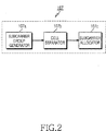
図2は、本発明による多重搬送波を用いる広帯域無線通信システムの副搬送波割り当て装置の構成を示すブロック図で、副搬送波割り当て装置は、副搬送波グループ生成部107a、セル区分部107b及び副搬送波割り当て部107cからなる図1の副チャネル割り当て器107とすることができる。
FIG. 2 is a block diagram illustrating a configuration of a subcarrier allocation apparatus of a broadband wireless communication system using multiple carriers according to the present invention. The subcarrier allocation apparatus includes a subcarrier
図2で、副搬送波グループ生成部107aは、一つのセルの副搬送波を、少なくとも一つの連続した副搬送波を含む複数の副搬送波グループに区分する。副搬送波グループの区分方式は、図3に基づいて後述する。また、セル区分部107bは、セル識別情報と複数のリードソロモン数列を用いてセル区分のための数列を生成し、副搬送波割り当て部107cは、セル区分のための数列と複数の副搬送波グループと関連する情報を用いて、複数の副搬送波を副チャネルに割り当てる。
In FIG. 2, the subcarrier
本発明において、セル区分数列は、各副搬送波グループに属する連続した副搬送波の個数がQ個の場合、Q2個のセル区分が可能なように構成され、副チャネル数列は、同一セル内で最大Q個の副チャネル割り当てが可能なように構成される。 In the present invention, the cell division number sequence, if the number of consecutive subcarriers belonging to each sub-carrier group is the Q, be configured to allow Q 2 pieces of cell division, the sub-channel number sequence in the same cell A maximum of Q subchannels can be allocated.
したがって、上記の構成によれば、セル区分個数と全体セルに割り当て可能な合計副チャネルの個数は、従来に比べて二乗倍で増加できる。 Therefore, according to the above configuration, the number of cell sections and the total number of subchannels that can be allocated to the entire cell can be increased by a factor of two compared to the conventional case.
以下、本発明の副搬送波割り当て方法と、本発明で定義されたセル区分数列及び副チャネル数列について詳細に説明する。 Hereinafter, the subcarrier allocation method of the present invention and the cell division number sequence and subchannel number sequence defined in the present invention will be described in detail.
図3は、本発明による多重搬送波を用いる広帯域無線通信システムにおける副搬送波割り当て方法を説明するための図である。 FIG. 3 is a diagram for explaining a subcarrier allocation method in a broadband wireless communication system using multiple carriers according to the present invention.
図3において、一つのセルに割り当てられる全体副搬送波210は、Q−1個のグループ(すなわち、副搬送波グループ220)に分けられ、各副搬送波グループ220は、Q個の連続した副搬送波210を含む。副搬送波が割り当てられる論理的位置を指示するRS Seqは、ガロア域(Galois Field:以下、“GF(Q)”という。)で定義される。GF(Q)は、特定演算に対して閉じており(Closed)、Q個の元素{0,1,2,..,Q−1}で構成される。GF(Q)が特定演算に対して閉じていると、その演算結果は、同一GF(Q)内に存在する。
In FIG. 3, the
Qが素数の場合、GF(Q)での加算と除算は、下記の<数式1>及び<数式2>によって定義される。
When Q is a prime number, addition and division by GF (Q) are defined by <

上記式1及び2中、演算子“mod”は、モジュレーション(modulation)を表す。
In the
本実施形態で、GF(Q)は、前記<数式1>及び<数式2>で定義される加算及び除算に対して閉じている。また、GF(Q)で定義される後述するセル区分数列Sm(m:セル番号)は、各副チャネルを形成する副搬送波210の論理的位置を決定するのに使われる特定セル番号によって決定される数列である。また、本実施形態では、セル区分数列と各副チャネルに該当するパラメータβを用いて、各副チャネルの副搬送波の位置を決定する副チャネル数列Sm,βを生成する。図3で、相異なる副搬送波グループ220に分けられて位置するQ−1個の副搬送波210は、基本的に一つの副チャネルを形成する(図3は、Q=7の例)。ここで、副チャネルを構成する副搬送波210の個数は、増減可能である。
In the present embodiment, GF (Q) is closed with respect to the addition and division defined by the above <
本発明において、副搬送波インデックスは、下記<数式3>で定められる。
In the present invention, the subcarrier index is defined by the following <
![]()
![]()
上記<数式3>で、Sub_carrier(i)は、副搬送波インデックスを表し、iは、副搬送波グループ220のインデックス(以下、“グループインデックス”という。)を表し、S(i)は、副チャネル数列Smβの(i+1)番目の元素で、該当の副搬送波グループ220の副搬送波210を表す。グループインデックスは、i=0,1,...,Q−2の形態に設定される。そして、副チャネル数列Sm,βが一つ定義されると、これによって該当セルに位置する副チャネルが一つ定義される。
In <
例えば、図3に示すように、<数式3>の副搬送波インデックスが{0,1,2,...,41}のように設定された全体42個の副搬送波210を、6個の副搬送波グループ220にすると、長さ6の副チャネル数列Sm,βを用いて、副チャネル0〜副チャネル6のうち一つに属する6個の副搬送波210を指定できる。すなわち、副チャネル数列Sm,βが{3,2,6,4,5,1}のように与えられと、該当するセルの副チャネルを構成する副搬送波インデックスは0〜5(i=0〜5)となるので、上記<数式3>によって{7*0+3,7*1+2,...,7*5+1}のように演算され、副搬送波のインデックスが{3,9,20,25,33,36}の副チャネルを構成する。
For example, as shown in FIG. 3, the subcarrier index of <
以下、セル区分数列Smと副チャネル数列Sm,βについてより詳細に説明する。 Hereinafter, the cell division number sequence S m and the subchannel number sequence S m, β will be described in more detail.
本発明でセル区分数列Smは、セル識別情報と複数の数列によって定義される。セル識別情報としては、例えば、セルIDを用い、複数の数列としては、本発明で定義された基本数列S0及びS1を用いる。該基本数列は2以上定義でき、本発明では好適に2つの基本数列を用いた例を説明する。 In the present invention, the cell division number sequence Sm is defined by cell identification information and a plurality of number sequences. For example, a cell ID is used as the cell identification information, and the basic number sequences S0 and S1 defined in the present invention are used as the plurality of number sequences. Two or more basic number sequences can be defined. In the present invention, an example in which two basic number sequences are preferably used will be described.
基本数列S0及びS1は、下記<数式4>で定義される。
The basic number sequences S0 and S1 are defined by the following <
上記<数式4>で、αは、GF(Q)の元素(Primitive Element)を表す。したがって、Q=7の場合に、α6mod7=1の演算によって、α=3がGF(Q)の元素となり、
S0={3,32,33,34,35,36}mod7={3,2,6,4,5,1}、
S1={32,34,36,32,34,36}mod7={2,4,1,2,4,1}となる。
In the above <
S0 = {3, 3 2 , 3 3 , 3 4 , 3 5 , 3 6 } mod 7 = { 3 , 2 , 6 , 4 , 5 , 1},
S1 = {3 2 , 3 4 , 3 6 , 3 2 , 3 4 , 3 6 } mod 7 = { 2 , 4 , 1 , 2 , 4 , 1}.
ここで、基本数列S0及びS1の元素は、循環遷移できる。 Here, the elements of the basic number sequences S0 and S1 can make a cyclic transition.
なお、本発明でm番セルに割り当てられるセル区分数列Smは、下記<数式5>で定義される。
In addition, the cell division number sequence Sm assigned to the m-th cell in the present invention is defined by the following <
上記<数式5>で、m=c0+Qc1と定義できる。m mod Q演算の商と余りはそれぞれ、c0、c1である。ここで、mは、セル識別情報、すなわち、セル番号(セルID)を表す。また、c0、c1は、セルを区分する因子で、互いに置換可能である。
In the above <
例えば、Q=7の場合、c0、c1はそれぞれ、0〜6の値を有し、前記c0、c1の組み合わせ可能な個数は、c0とc1がそれぞれQ個なのでQ2個であり、その結果、7の二乗である49個のセル区分が可能である。したがって、上記<数式5>によれば、Q2個のセル区分が可能である。
For example, for Q = 7,
一方、m番目のセル内の各副チャネルを指定するための副チャネル数列Sm,βは、下記<数式6>のように、所定のオフセット値(Offset)βが加算されることによって算出される。
On the other hand, the sub-channel number sequence S m, β for designating each sub-channel in the mth cell is calculated by adding a predetermined offset value (Offset) β as shown in the following <
上記<数式6>で、βは、例えば、0〜Q−1の値を有するので、<数式6>によれば、一つのセル内で最大Q個の副チャネルが割り当てられることができる。
In <
上記の方式によれば、上記<数式5>のセル区分数列Smによって最大Q2個のセル区分が可能であり、上記<数式6>の副チャネル数列Smβによって、一つのセルで最大Q個の副チャネルが割り当てられることができる。したがって、全体セルに割り当て可能な合計副チャネルの個数は、最大でQ3である。
According to the above method, a maximum of Q 2 cell partitions can be performed by the cell partition sequence Sm of the above <
また、上記の過程によって求められるセル区分数列は、隣接するセル間に2個以下の衝突を起こす良好な特性を呈する。もし、上記<数式5>で、全てのセルに対してc1=0とする(セル個数を従来個数に維持する)と、セル区分数列Smは一般のRS Seqとなり、この場合、隣接するセル間に最大でも1つの衝突しか発生しない。 In addition, the cell division number sequence obtained by the above process exhibits good characteristics that cause two or less collisions between adjacent cells. If c 1 = 0 is set for all the cells in the above formula 5 (the number of cells is maintained at the conventional number), the cell division number sequence Sm is a general RS Seq, and in this case, adjacent cells There is at most one collision in between.
一方、下記<表1>は、例えば、一つの基地局セルを形成する、例えば、セル番号m=1(すなわち、c0=1、c1=0)を有する基地局の複数の副チャネル数列を示すもので、上記<数式6>によって決定される。
On the other hand, <Table 1> below, for example, forms a single base station cell, for example, a plurality of subchannel sequence numbers of base stations having cell number m = 1 (ie, c 0 = 1, c 1 = 0) This is determined by the above-described <
また、下記の<表2>は、基地局別に複数のセル区分数列を表すもので、例えば、GF(7)で、α=3、S0={3,2,6,4,5,1}、S1={2,4,1,2,4,1}の場合を示している。 <Table 2> below represents a plurality of cell division number sequences for each base station. For example, GF (7), α = 3, S0 = {3, 2, 6, 4, 5, 1} , S1 = {2, 4, 1, 2, 4, 1}.
上記<表2>は、例えば、Q=7の場合で、最大でQ2=49個、すなわち、S0からS48まで合計49個のセル区分が可能であるが、説明の便宜上、一部のみを表示した。 In Table 2 above, for example, in the case of Q = 7, a maximum of Q 2 = 49 cells, that is, a total of 49 cell segments from S 0 to S 48 are possible. Only displayed.
上記<表1>は、1番基地局(すなわち、m=1)に対する副チャネル数列で、これを、<表2>の他のセルの副チャネル0番数列と比較すると、両セルとも、c1=0の場合(例えば、<表2>のS0からS6まで、及び<表1>の各副チャネル数列)には、最大限でも1ヶ所でしか衝突が発生しなく、そうでない場合(例えば、<表2>のS7からS13まで、及び<表1>の各副チャネル数列)は、最大で2ヶ所で衝突が発生することが分かる。
<Table 1> is a subchannel number sequence for the first base station (that is, m = 1). When this is compared with the
一方、本実施形態では、基本的に、<数式5>をセル区分数列とし、<数式6>を副チャネル数列としたが、これらを変形しセル区分数列と副チャネル数列を他の方式で得ることも可能である。例えば、セル区分数列と副チャネル数列は、下記<数式7>のようにしても良い。
On the other hand, in the present embodiment, <
下記の<数式7>で、S’は、セル区分数列の役割を担い、S”は、副チャネル数列の役割を担う。この場合、副チャネル間の衝突数においては、上記の基本的な方法による場合と違いがない。これら方法の他にも様々な方法が可能である。上記<数式7>で定義される本発明の実施形態において、副搬送波インデックスは、<数式3>または下記の<数式9>によって定められても良い。
In the following <Equation 7>, S ′ plays a role of cell division sequence, and S ″ plays a role of subchannel number sequence. In this case, the above basic method is used for the number of collisions between subchannels. In addition to these methods, various other methods are possible, and in the embodiment of the present invention defined by the above <Formula 7>, the subcarrier index is represented by <
また、上記実施形態では、一つの副チャネル当たり副搬送波の個数を(Q−1)と設定したが、これに限定されるものではない。したがって、副搬送波個数が(Q−1)よりも少ないと、数列を、必要な副搬送波個数だけ切り取って使用する。例えば、副搬送波個数が(Q−M)個に設定されると、基本数列S0、S1は、下記<数式8>のように変形される。 In the above embodiment, the number of subcarriers per subchannel is set to (Q-1). However, the present invention is not limited to this. Therefore, if the number of subcarriers is less than (Q-1), the sequence is used by cutting out the necessary number of subcarriers. For example, when the number of subcarriers is set to (Q−M), the basic number sequences S0 and S1 are modified as in the following <Equation 8>.
すなわち、本来の数列において前の(Q−M)個に該当する副搬送波を使用する。同様な方法で、副チャネル当りの副搬送波個数が(Q−1)よりも大きく設定され場合は、基本数列を繰り返し使用して所望の副搬送波個数を得る。例えば、各副チャネルが、副搬送波個数を2*(Q−1)個含むと、基本数列S0、S1を2回繰り返して使用する。 That is, subcarriers corresponding to the previous (QM) in the original sequence are used. In the same way, when the number of subcarriers per subchannel is set to be larger than (Q-1), the basic number sequence is repeatedly used to obtain a desired number of subcarriers. For example, if each subchannel includes 2 * (Q-1) subcarriers, the basic number sequences S0 and S1 are used twice.
図3は、GF(7)での設計によって、42個の副搬送波を7個の副チャネルに割り当てる方法を概略的に示す図である。図3を参照すると、セル2とセル3との間では、副チャネル間の衝突(点線四角の部分)が2回発生する。しかしながら、セル1とセル2間では、副チャネル間の衝突が最大限でも1回しか発生しないことが確認できる。
FIG. 3 is a diagram schematically illustrating a method of assigning 42 subcarriers to 7 subchannels by designing with GF (7). Referring to FIG. 3, between the
一方、周波数再使用率が1の無線通信システムでは、基地局設置を容易にするには区分可能なセル数を増やさなければならない。このため、副搬送波割り当てを一つのOFDMシンボルで行わず、複数のシンボルをまとめて副搬送波を割り当てる。しかしながら、この場合、フレーム構造が、副搬送波割り当てに使われるOFDMシンボル数によって制約を受けるという不具合がある。 On the other hand, in a radio communication system having a frequency reuse factor of 1, the number of cells that can be classified must be increased in order to facilitate base station installation. For this reason, subcarrier allocation is not performed with one OFDM symbol, but a plurality of symbols are collectively allocated to subcarriers. However, in this case, there is a problem that the frame structure is restricted by the number of OFDM symbols used for subcarrier allocation.
本発明によれば、副搬送波割り当て時に、基本割り当て単位のシンボル数を、必要な場合、従来に比べて自乗倍に拡張可能である。 According to the present invention, at the time of subcarrier allocation, the number of symbols in the basic allocation unit can be expanded to the square of the conventional number when necessary.
一方、Q(Q−1)個の副搬送波を使用する場合、各OFDMシンボルでQ*N個の副搬送波を用いてN個の副搬送波グループを定義し、(Q−1)/N個のOFDMシンボルを使用すると、副搬送波のインデックスは、下記<数式9>によって算出される。 On the other hand, when Q (Q-1) subcarriers are used, N subcarrier groups are defined using Q * N subcarriers in each OFDM symbol, and (Q-1) / N When the OFDM symbol is used, the subcarrier index is calculated by the following <Equation 9>.
![]()
![]()
上記<数式9>で、例えば、Q=7、N=2の場合、副搬送波グループ220のグループインデックス(Group Index)iは、0から5(すなわち、0からQ−2)までの値を有し、シンボルインデックスnは、0または1の値を有する。上記<数式9>で、
For example, when Q = 7 and N = 2 in the above-described <Equation 9>, the group index (Group Index) i of the
![]()
![]()
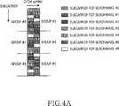
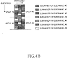
図4A及び図4Bは、Qは7、Nはそれぞれ2及び3のときに、上記<数式9>によって副搬送波を副チャネルに割り当てる方法を示す図である。 4A and 4B are diagrams illustrating a method of assigning subcarriers to subchannels according to the above-described <Equation 9> when Q is 7 and N is 2 and 3, respectively.
すなわち、図4Aは、2シンボルを使用する場合、図4Bは、3シンボルを使用する場合における本発明による副搬送波割り当てをそれぞれ示している。図3に示す副搬送波割り当てによれば、異なるセルに属する異なる副チャネル間で最大で2個の副搬送波衝突が起こる。これに対し、上記<数学式9>を用いて各副チャネルインデックスを計算すると、GF(Q)で定義された数列を使用した場合、0〜(Q−1)番セルに属する副チャネル間では、最大でも1個しか副搬送波衝突が起きず、同様に、Q〜(2Q−1)番、2Q〜(3Q−1)番等、各Q個のセルに属する副チャネル間では、最大でも1個の副搬送波衝突しか起こらないということが分かる。 That is, FIG. 4A shows subcarrier allocation according to the present invention when 2 symbols are used, and FIG. 4B shows when 3 symbols are used. According to the subcarrier allocation shown in FIG. 3, a maximum of two subcarrier collisions occur between different subchannels belonging to different cells. On the other hand, when each subchannel index is calculated using <Mathematical formula 9> above, when the sequence defined by GF (Q) is used, between the subchannels belonging to the 0th to (Q-1) th cells, , Only one subcarrier collision occurs at most, and similarly, at most 1 between subchannels belonging to Q cells such as Q to (2Q-1), 2Q to (3Q-1), etc. It can be seen that only one subcarrier collision occurs.
101 CRC挿入器
103 エンコーダ(Encoder)
105 シンボルマッピング器(Symbol Mapper)
107 副チャネル割り当て器(Sub-Channel Allocator)
109 直列/並列変換器
111 パイロット(Pilot)シンボル挿入器
113 IFFT(Inverse Fast Fourier Transform)変換器
115 並列/直列変換器
117 保護区間(Guard Interval)挿入器
119 D/A(Digital/Analog)変換器
121 RF(Radio Frequency)処理器
101
105 Symbol Mapper
107 Sub-Channel Allocator
109 Serial /
Claims (33)
個数Aの副チャネルを割り当てる過程であって、前記個数Aの副チャネルのそれぞれは、セル区分数列を用いて、個数Bの副搬送波グループのそれぞれから選択された少なくとも1つの副搬送波を含む過程を備え、
個数Cの副搬送波は、前記個数Bの副搬送波グループにグループ化され、前記個数Bの副搬送波グループのそれぞれは、個数Qの連続した副搬送波を含み、前記個数A、B、C及びQは1以上の整数であり、
セル番号mのための前記セル区分数列は、c0によって与えられる第1のベースシーケンスS0と、c1によって与えられる第2のベースシーケンスS1と、の合計に基づいて決定され、ここで、c0及びc1は、mをQで割ったときの商と余りである
ことを特徴とする、方法。In a method for assigning subchannels by a base station in a wireless communication system,
A process of allocating a number A of subchannels, wherein each of the number A of subchannels includes at least one subcarrier selected from each of a number B of subcarrier groups using a cell division sequence. Prepared,
The number C of subcarriers are grouped into the number B of subcarrier groups, and each of the number B of subcarrier groups includes Q consecutive subcarriers, and the numbers A, B, C, and Q are An integer greater than or equal to 1,
The cell partition sequence for cell number m is determined based on the sum of the first base sequence S0 given by c0 and the second base sequence S1 given by c1, where c0 and c1 Is the quotient and remainder when m is divided by Q. The method.
個数Aの副チャネルを割り当てる副搬送波割り当て部であって、前記個数Aの副チャネルのそれぞれは、セル区分数列を用いて、個数Bの副搬送波グループのそれぞれから選択された少なくとも1つの副搬送波を含む副搬送波割り当て部、を備え、
個数Cの副搬送波は、前記個数Bの副搬送波グループにグループ化され、前記個数Bの副搬送波グループのそれぞれは、個数Qの連続した副搬送波を含み、前記個数A、B、C及びQは1以上の整数であり、
セル番号mのための前記セル区分数列は、c0によって与えられる第1のベースシーケンスS0と、c1によって与えられる第2のベースシーケンスS1と、の合計に基づいて決定され、ここで、c0及びc1は、mをQで割ったときの商と余りである
ことを特徴とする、装置。In an apparatus for assigning a secondary channel in a wireless communication system ,
A subcarrier allocating unit that allocates a number A of subchannels, wherein each of the number A of subchannels includes at least one subcarrier selected from each of a number B of subcarrier groups using a cell division sequence. A subcarrier allocation unit including
The number C of subcarriers are grouped into the number B of subcarrier groups, and each of the number B of subcarrier groups includes Q consecutive subcarriers, and the numbers A, B, C, and Q are An integer greater than or equal to 1,
The cell partition sequence for cell number m is determined based on the sum of a first base sequence S0 given by c0 and a second base sequence S1 given by c1, where c0 and c1 Is the quotient when m is divided by Q and the remainder .
請求項18に記載の装置:
The apparatus of claim 18 :
Applications Claiming Priority (2)
| Application Number | Priority Date | Filing Date | Title |
|---|---|---|---|
| KR20040015985 | 2004-03-05 | ||
| PCT/KR2005/000623 WO2005086447A1 (en) | 2004-03-05 | 2005-03-05 | Method and apparatus for allocating subcarriers in a broadband wireless communication system using multiple carriers |
Publications (2)
| Publication Number | Publication Date |
|---|---|
| JP2007526716A JP2007526716A (en) | 2007-09-13 |
| JP4358271B2 true JP4358271B2 (en) | 2009-11-04 |
Family
ID=36950976
Family Applications (1)
| Application Number | Title | Priority Date | Filing Date |
|---|---|---|---|
| JP2007501723A Expired - Fee Related JP4358271B2 (en) | 2004-03-05 | 2005-03-05 | Subcarrier allocation method and apparatus in broadband wireless communication system using multiple carriers |
Country Status (9)
| Country | Link |
|---|---|
| US (1) | US7646800B2 (en) |
| JP (1) | JP4358271B2 (en) |
| KR (1) | KR100707052B1 (en) |
| CN (1) | CN1930840B (en) |
| AU (1) | AU2005219907B2 (en) |
| BR (1) | BRPI0508465A (en) |
| CA (1) | CA2556948C (en) |
| RU (2) | RU2335089C2 (en) |
| WO (1) | WO2005086447A1 (en) |
Families Citing this family (29)
| Publication number | Priority date | Publication date | Assignee | Title |
|---|---|---|---|---|
| US8713623B2 (en) | 2001-09-20 | 2014-04-29 | Time Warner Cable Enterprises, LLC | Technique for effectively providing program material in a cable television system |
| JP2005091698A (en) * | 2003-09-17 | 2005-04-07 | Ngk Insulators Ltd | Optical modulator |
| KR100842588B1 (en) * | 2004-03-12 | 2008-07-01 | 삼성전자주식회사 | Method and Apparatus for allocating sub-carriers broadband wireless communication system using multiple carriers |
| US9723267B2 (en) | 2004-12-15 | 2017-08-01 | Time Warner Cable Enterprises Llc | Method and apparatus for wideband distribution of content |
| US8644130B2 (en) * | 2005-03-18 | 2014-02-04 | Samsung Electronics Co., Ltd. | System and method for subcarrier allocation in a wireless multihop relay network |
| KR101137329B1 (en) * | 2005-06-15 | 2012-04-19 | 엘지전자 주식회사 | Method and apparatus for allocating subcarriers in OFDMA |
| GB2429875B (en) * | 2005-09-05 | 2008-03-12 | Toshiba Res Europ Ltd | Improved broadband carrier frequency selection |
| CN1953364B (en) * | 2005-10-20 | 2010-05-05 | 华为技术有限公司 | A realization method for channel in multicarrier wave system cell |
| US7983350B1 (en) * | 2005-10-25 | 2011-07-19 | Altera Corporation | Downlink subchannelization module |
| KR101035083B1 (en) * | 2006-04-26 | 2011-05-19 | 재단법인서울대학교산학협력재단 | Method and system for using resource in a multi-cell communication system |
| ATE532305T1 (en) * | 2006-07-28 | 2011-11-15 | Qualcomm Inc | DATA ENCODING METHOD AND APPARATUS FOR FLASH SIGNALING |
| BRPI0717892B1 (en) | 2006-11-01 | 2020-09-24 | Qualcomm Incorporated | METHOD AND APPARATUS FOR SEARCHING A CELL IN AN ORTHOGONAL WIRELESS COMMUNICATION SYSTEM |
| US20080107013A1 (en) * | 2006-11-06 | 2008-05-08 | Nokia Corporation | Signature generation using coded waveforms |
| AU2012227366B2 (en) * | 2007-11-26 | 2014-02-13 | Sharp Kabushiki Kaisha | Base station device, mobile terminal device, wireless communication system, and wireless communication method |
| EA018288B1 (en) * | 2007-11-26 | 2013-06-28 | Шарп Кабусики Кайся | Base station device, mobile station device, wireless communication system and wireless communication method |
| US8238304B2 (en) * | 2008-03-31 | 2012-08-07 | Qualcomm Incorporated | Apparatus and method for channel resource description |
| CN101616438A (en) * | 2008-06-24 | 2009-12-30 | 华为技术有限公司 | The emission of multicarrier system signal, method of reseptance and device |
| US9369990B2 (en) | 2008-08-11 | 2016-06-14 | Qualcomm Incorporated | Multi-carrier design for control and procedures |
| WO2010044627A2 (en) | 2008-10-15 | 2010-04-22 | (주)엘지전자 | Method and apparatus for sending and receiving multi-carrier information in multi-carrier communication system |
| KR101507087B1 (en) * | 2009-01-07 | 2015-03-30 | 삼성전자주식회사 | Apparatus and method for transmitting/receiving secondary synchronization channel in a broadband wireless communication system |
| US8780834B2 (en) * | 2009-04-15 | 2014-07-15 | Lg Electronics Inc. | Center frequency control method in wireless access system |
| WO2010131446A1 (en) * | 2009-05-13 | 2010-11-18 | パナソニック株式会社 | Radio communication device and radio communication method |
| KR101685173B1 (en) | 2009-07-13 | 2016-12-12 | 주식회사 팬택 | Method and apparatus for sequence generation in wireless communication system |
| WO2011025131A2 (en) * | 2009-08-28 | 2011-03-03 | Lg Electronics Inc. | Method and apparatus for transmitting pilot in wireless communication system |
| US9300445B2 (en) | 2010-05-27 | 2016-03-29 | Time Warner Cable Enterprise LLC | Digital domain content processing and distribution apparatus and methods |
| US9185341B2 (en) | 2010-09-03 | 2015-11-10 | Time Warner Cable Enterprises Llc | Digital domain content processing and distribution apparatus and methods |
| US9596637B2 (en) | 2012-11-05 | 2017-03-14 | Apple Inc. | Dynamically adapting wireless communication |
| GB2511089A (en) | 2013-02-22 | 2014-08-27 | Ibm | All-to-all message exchange in parallel computing systems |
| WO2019125374A1 (en) * | 2017-12-18 | 2019-06-27 | Intel IP Corporation | Methods and apparatus to mitigate coexistence interference in a wireless network |
Family Cites Families (22)
| Publication number | Priority date | Publication date | Assignee | Title |
|---|---|---|---|---|
| IL103620A0 (en) | 1992-11-03 | 1993-04-04 | Rafael Armament Dev Authority | Spread-spectrum,frequency-hopping radiotelephone system |
| US5726978A (en) | 1995-06-22 | 1998-03-10 | Telefonaktiebolaget L M Ericsson Publ. | Adaptive channel allocation in a frequency division multiplexed system |
| GB2307826B (en) * | 1995-11-28 | 2000-01-19 | Int Mobile Satellite Org | Communication method and apparatus |
| JPH09270053A (en) * | 1996-03-29 | 1997-10-14 | Mitsubishi Electric Corp | Device for issuing identification number and device for inspecting identification number |
| US6151296A (en) | 1997-06-19 | 2000-11-21 | Qualcomm Incorporated | Bit interleaving for orthogonal frequency division multiplexing in the transmission of digital signals |
| US6269245B1 (en) * | 1998-09-10 | 2001-07-31 | Hughes Electronics Corporation | Cellular communication system employing dynamic preferential channel allocation |
| US7418043B2 (en) * | 2000-07-19 | 2008-08-26 | Lot 41 Acquisition Foundation, Llc | Software adaptable high performance multicarrier transmission protocol |
| US7224741B1 (en) * | 2000-07-24 | 2007-05-29 | Zion Hadad | System and method for cellular communications |
| US6947748B2 (en) * | 2000-12-15 | 2005-09-20 | Adaptix, Inc. | OFDMA with adaptive subcarrier-cluster configuration and selective loading |
| US7164669B2 (en) * | 2001-01-19 | 2007-01-16 | Adaptix, Inc. | Multi-carrier communication with time division multiplexing and carrier-selective loading |
| WO2004038972A1 (en) * | 2002-10-26 | 2004-05-06 | Electronics And Telecommunications Research Institute | Frequency hopping ofdma method using symbols of comb pattern |
| WO2004077777A1 (en) * | 2003-02-28 | 2004-09-10 | Nortel Networks Limited | Sub-carrier allocation for ofdm |
| KR100710167B1 (en) * | 2003-07-08 | 2007-04-20 | 엘지.필립스 엘시디 주식회사 | driving circuit of back light |
| KR100929100B1 (en) * | 2003-07-18 | 2009-11-30 | 삼성전자주식회사 | Apparatus and Method for Allocating Subchannels in Communication System Using Orthogonal Frequency Division Multiple Access |
| KR100640461B1 (en) * | 2003-07-30 | 2006-10-30 | 삼성전자주식회사 | Apparatus and method for assigning sub channel in a communication system using orthogonal frequency division multiple access scheme |
| KR100505968B1 (en) * | 2003-08-27 | 2005-08-03 | 삼성전자주식회사 | METHOD OF CONSTRUCTING WIRELESS NETWORK OF Orthogonal Frequency Division Multiple Access, AND TERMINAL OF ACCEPTING OFDMA |
| KR100876757B1 (en) | 2003-10-31 | 2009-01-07 | 삼성전자주식회사 | System and method for consturcting sub channel in a communication system |
| KR20050049140A (en) * | 2003-11-21 | 2005-05-25 | 삼성전자주식회사 | Method for embodying uplink fram of wireless communication system based on ofdma |
| KR100507541B1 (en) * | 2003-12-19 | 2005-08-09 | 삼성전자주식회사 | Data and pilot carrier allocation method and receiving method, receiving apparatus and, sending method, sending apparatus in ofdm system |
| KR100651454B1 (en) | 2004-03-05 | 2006-11-29 | 삼성전자주식회사 | Method for allocating a subchannel in an orthogonal frequency division multiple access cellular communication system |
| KR100842588B1 (en) * | 2004-03-12 | 2008-07-01 | 삼성전자주식회사 | Method and Apparatus for allocating sub-carriers broadband wireless communication system using multiple carriers |
| EP2442513A1 (en) * | 2004-06-24 | 2012-04-18 | Nortel Networks Limited | Preambles in OFDMA System |
-
2005
- 2005-03-05 CN CN2005800072140A patent/CN1930840B/en not_active Expired - Fee Related
- 2005-03-05 BR BRPI0508465-2A patent/BRPI0508465A/en not_active IP Right Cessation
- 2005-03-05 CA CA2556948A patent/CA2556948C/en not_active Expired - Fee Related
- 2005-03-05 RU RU2006131675/09A patent/RU2335089C2/en not_active IP Right Cessation
- 2005-03-05 WO PCT/KR2005/000623 patent/WO2005086447A1/en active Application Filing
- 2005-03-05 AU AU2005219907A patent/AU2005219907B2/en not_active Ceased
- 2005-03-05 JP JP2007501723A patent/JP4358271B2/en not_active Expired - Fee Related
- 2005-03-05 KR KR1020050018475A patent/KR100707052B1/en active IP Right Grant
- 2005-03-07 US US11/074,043 patent/US7646800B2/en not_active Expired - Fee Related
-
2008
- 2008-04-17 RU RU2008115261/09A patent/RU2008115261A/en not_active Application Discontinuation
Also Published As
| Publication number | Publication date |
|---|---|
| US7646800B2 (en) | 2010-01-12 |
| KR20060043437A (en) | 2006-05-15 |
| CA2556948A1 (en) | 2005-09-15 |
| RU2006131675A (en) | 2008-03-10 |
| RU2335089C2 (en) | 2008-09-27 |
| RU2008115261A (en) | 2009-10-27 |
| JP2007526716A (en) | 2007-09-13 |
| BRPI0508465A (en) | 2007-07-31 |
| KR100707052B1 (en) | 2007-04-13 |
| US20050195910A1 (en) | 2005-09-08 |
| AU2005219907A1 (en) | 2005-09-15 |
| WO2005086447A1 (en) | 2005-09-15 |
| CA2556948C (en) | 2011-01-18 |
| CN1930840B (en) | 2010-05-05 |
| AU2005219907B2 (en) | 2008-08-21 |
| CN1930840A (en) | 2007-03-14 |
Similar Documents
| Publication | Publication Date | Title |
|---|---|---|
| JP4358271B2 (en) | Subcarrier allocation method and apparatus in broadband wireless communication system using multiple carriers | |
| JP4629054B2 (en) | Subchannel signal transmission apparatus and method in communication system using orthogonal frequency division multiple access system | |
| KR100640461B1 (en) | Apparatus and method for assigning sub channel in a communication system using orthogonal frequency division multiple access scheme | |
| JP4510077B2 (en) | Apparatus and method for generating preamble sequence for adaptive antenna system in orthogonal frequency division multiple access communication system | |
| KR100876757B1 (en) | System and method for consturcting sub channel in a communication system | |
| RU2374775C2 (en) | Limited switching of channels in wireless communication systems | |
| KR100842588B1 (en) | Method and Apparatus for allocating sub-carriers broadband wireless communication system using multiple carriers | |
| EP2183895B1 (en) | Transmission of data using repetition coding with PAPR reduction | |
| KR20070110807A (en) | Apparatus and method for allocating resource in orthogonal frequency division multiple access system | |
| KR100929100B1 (en) | Apparatus and Method for Allocating Subchannels in Communication System Using Orthogonal Frequency Division Multiple Access | |
| WO2008054128A1 (en) | Method for allocating pilots | |
| KR20070093657A (en) | Method and apparatus for allocating resource in orthogonal frequency division multiple access system | |
| KR100860698B1 (en) | Apparatus and method for allocating sub channels in a communication system | |
| KR20070104177A (en) | Method and apparatus for allocating forward resource in orthogonal frequency division multiple access system and system thereof |
Legal Events
| Date | Code | Title | Description |
|---|---|---|---|
| A131 | Notification of reasons for refusal |
Free format text: JAPANESE INTERMEDIATE CODE: A131 Effective date: 20090317 |
|
| A521 | Request for written amendment filed |
Free format text: JAPANESE INTERMEDIATE CODE: A523 Effective date: 20090617 |
|
| TRDD | Decision of grant or rejection written | ||
| A01 | Written decision to grant a patent or to grant a registration (utility model) |
Free format text: JAPANESE INTERMEDIATE CODE: A01 Effective date: 20090707 |
|
| A01 | Written decision to grant a patent or to grant a registration (utility model) |
Free format text: JAPANESE INTERMEDIATE CODE: A01 |
|
| A61 | First payment of annual fees (during grant procedure) |
Free format text: JAPANESE INTERMEDIATE CODE: A61 Effective date: 20090805 |
|
| FPAY | Renewal fee payment (event date is renewal date of database) |
Free format text: PAYMENT UNTIL: 20120814 Year of fee payment: 3 |
|
| R150 | Certificate of patent or registration of utility model |
Free format text: JAPANESE INTERMEDIATE CODE: R150 Ref document number: 4358271 Country of ref document: JP Free format text: JAPANESE INTERMEDIATE CODE: R150 |
|
| S111 | Request for change of ownership or part of ownership |
Free format text: JAPANESE INTERMEDIATE CODE: R313113 |
|
| FPAY | Renewal fee payment (event date is renewal date of database) |
Free format text: PAYMENT UNTIL: 20120814 Year of fee payment: 3 |
|
| R350 | Written notification of registration of transfer |
Free format text: JAPANESE INTERMEDIATE CODE: R350 |
|
| FPAY | Renewal fee payment (event date is renewal date of database) |
Free format text: PAYMENT UNTIL: 20130814 Year of fee payment: 4 |
|
| R250 | Receipt of annual fees |
Free format text: JAPANESE INTERMEDIATE CODE: R250 |
|
| R250 | Receipt of annual fees |
Free format text: JAPANESE INTERMEDIATE CODE: R250 |
|
| R250 | Receipt of annual fees |
Free format text: JAPANESE INTERMEDIATE CODE: R250 |
|
| R250 | Receipt of annual fees |
Free format text: JAPANESE INTERMEDIATE CODE: R250 |
|
| R250 | Receipt of annual fees |
Free format text: JAPANESE INTERMEDIATE CODE: R250 |
|
| R250 | Receipt of annual fees |
Free format text: JAPANESE INTERMEDIATE CODE: R250 |
|
| R250 | Receipt of annual fees |
Free format text: JAPANESE INTERMEDIATE CODE: R250 |
|
| LAPS | Cancellation because of no payment of annual fees |