JP4356548B2 - Board connector - Google Patents
Board connector Download PDFInfo
- Publication number
- JP4356548B2 JP4356548B2 JP2004211855A JP2004211855A JP4356548B2 JP 4356548 B2 JP4356548 B2 JP 4356548B2 JP 2004211855 A JP2004211855 A JP 2004211855A JP 2004211855 A JP2004211855 A JP 2004211855A JP 4356548 B2 JP4356548 B2 JP 4356548B2
- Authority
- JP
- Japan
- Prior art keywords
- terminal
- main body
- fitting
- reinforcing
- relay
- Prior art date
- Legal status (The legal status is an assumption and is not a legal conclusion. Google has not performed a legal analysis and makes no representation as to the accuracy of the status listed.)
- Active
Links
Images


Classifications
-
- H—ELECTRICITY
- H01—ELECTRIC ELEMENTS
- H01R—ELECTRICALLY-CONDUCTIVE CONNECTIONS; STRUCTURAL ASSOCIATIONS OF A PLURALITY OF MUTUALLY-INSULATED ELECTRICAL CONNECTING ELEMENTS; COUPLING DEVICES; CURRENT COLLECTORS
- H01R13/00—Details of coupling devices of the kinds covered by groups H01R12/70 or H01R24/00 - H01R33/00
- H01R13/46—Bases; Cases
- H01R13/502—Bases; Cases composed of different pieces
- H01R13/504—Bases; Cases composed of different pieces different pieces being moulded, cemented, welded, e.g. ultrasonic, or swaged together
-
- H—ELECTRICITY
- H01—ELECTRIC ELEMENTS
- H01R—ELECTRICALLY-CONDUCTIVE CONNECTIONS; STRUCTURAL ASSOCIATIONS OF A PLURALITY OF MUTUALLY-INSULATED ELECTRICAL CONNECTING ELEMENTS; COUPLING DEVICES; CURRENT COLLECTORS
- H01R12/00—Structural associations of a plurality of mutually-insulated electrical connecting elements, specially adapted for printed circuits, e.g. printed circuit boards [PCB], flat or ribbon cables, or like generally planar structures, e.g. terminal strips, terminal blocks; Coupling devices specially adapted for printed circuits, flat or ribbon cables, or like generally planar structures; Terminals specially adapted for contact with, or insertion into, printed circuits, flat or ribbon cables, or like generally planar structures
- H01R12/70—Coupling devices
- H01R12/71—Coupling devices for rigid printing circuits or like structures
- H01R12/72—Coupling devices for rigid printing circuits or like structures coupling with the edge of the rigid printed circuits or like structures
- H01R12/722—Coupling devices for rigid printing circuits or like structures coupling with the edge of the rigid printed circuits or like structures coupling devices mounted on the edge of the printed circuits
- H01R12/724—Coupling devices for rigid printing circuits or like structures coupling with the edge of the rigid printed circuits or like structures coupling devices mounted on the edge of the printed circuits containing contact members forming a right angle
Landscapes
- Connector Housings Or Holding Contact Members (AREA)
- Coupling Device And Connection With Printed Circuit (AREA)
Description
本発明は、基板用コネクタに関する。 The present invention relates to a board connector.
従来、基板に接続される基板用コネクタの一例として下記特許文献1に記載されたものが知られている。このものは、基板に取り付けられるハウジングに、端子金具を貫通した状態で保持可能な端子保持部が設けられており、端子金具は、端子保持部から後方へ突出した部分が下方へ屈曲されるとともにその下端部が基板に対して半田付けされることで接続されている。
上記のような基板用コネクタでは、例えば基板とハウジングとの熱膨張率の相違によって両者間に相対的な位置ずれが生じた場合には、端子金具のうち端子保持部から後方へ突出した部分がその軸線方向と交差する方向へ変位することで、位置ずれに伴って作用する衝撃が吸収されるようになっている。
この衝撃吸収性能の向上が求められる場合があり、その場合には、例えば端子金具における可動部分を延長することが考えられるが、そうするとコネクタ全体が大型化することになってしまう。また端子保持部を単に薄したのでは、端子保持部の強度を十分に保つことができなくなるおそれがあるため、簡単には対応できなかった。
本発明は上記のような事情に基づいて完成されたものであって、大型化や強度低下を招くことなく衝撃吸収性能を高めることを目的とする。
In the board connector as described above, for example, when a relative positional shift occurs between the board and the housing due to a difference in coefficient of thermal expansion, a portion of the terminal fitting that protrudes rearward from the terminal holding part is By displacing in the direction intersecting the axial direction, the impact acting with the positional deviation is absorbed.
In some cases, it is necessary to improve the shock absorbing performance. In this case, for example, it is conceivable to extend the movable part of the terminal fitting, but this increases the size of the entire connector. Further, simply thinning the terminal holding part may not be able to easily cope with the possibility that the strength of the terminal holding part may not be sufficiently maintained.
The present invention has been completed based on the above-described circumstances, and an object thereof is to improve impact absorption performance without causing an increase in size or a decrease in strength.
上記の目的を達成するための手段として、請求項1の発明は、コネクタハウジングには、端子金具を後方へ突出した状態で保持可能な端子保持部が設けられるとともに、前記端子金具における突出部分の端部が基板に対して接続されるものにおいて、前記端子保持部における端子金具の周りには、端子金具がその軸線方向と交差する二方向へ自由に弾性変形することを許容する変位許容領域が設けられ、この変位許容領域は、端子保持部の強度を保つための補強部を有し、その補強部は前記変位許容領域が各端子金具毎に互いに独立した形態となるよう、略格子状をなしており、前記コネクタハウジングの周りには、二次成形部が二次成形され、且つ前記二次成形部は、前記端子保持部のうち少なくとも前記補強部の周面を覆う形態とされ、前記端子保持部は、本体部と、嵌合筒部を有しその嵌合筒部が前記本体部の前面側に嵌合して組み付けられる中継端子用ホルダとから構成されるとともに、前記端子金具は、前記本体部に後方へ突出した状態で装着される端子本体と、前記中継端子ホルダに装着される中継端子とから構成されており、前記中継端子は、前後に一対の接続部を有しており、このうち後側の接続部が前記中継端子ホルダを前記本体部に組み付けるのに伴って前記端子本体に接続され、前側の接続部が前記コネクタハウジングに対して嵌合される相手コネクタと接続されるようになっている構成としたところに特徴を有する。 As a means for achieving the above object, according to the first aspect of the present invention, the connector housing is provided with a terminal holding portion capable of holding the terminal fitting in a state of protruding backward, and the protruding portion of the terminal fitting is provided. In the case where the end portion is connected to the substrate, a displacement permissible region that allows the terminal fitting to freely elastically deform in two directions intersecting the axial direction is provided around the terminal fitting in the terminal holding portion. The displacement permissible region has a reinforcing portion for maintaining the strength of the terminal holding portion, and the reinforcing portion has a substantially lattice shape so that the displacement permissible region is independent from each other for each terminal fitting. None has, around the connector housing, the secondary molded part is post-forming,且 one said secondary molding unit is a cover the peripheral surface of at least the reinforcing portion of the terminal holding portion, The terminal holding part is composed of a main body part and a relay terminal holder which has a fitting cylinder part and the fitting cylinder part is fitted and assembled to the front side of the main body part. Is composed of a terminal main body mounted in a state protruding rearward from the main body, and a relay terminal mounted on the relay terminal holder, and the relay terminal has a pair of connecting portions on the front and rear sides. And a mating connector in which the rear connection portion is connected to the terminal body as the relay terminal holder is assembled to the main body portion, and the front connection portion is fitted to the connector housing. It is characterized in that it is configured to be connected .
請求項2の発明は、請求項1に記載のものにおいて、前記端子保持部には、前記端子金具よりも後方へ延出する壁部が設けられ、この壁部が二次成形時に使用される金型によって保持されるようになっているとともに、前記壁部と前記端子保持部とを連結する補強壁が設けられているところに特徴を有する。 According to a second aspect of the present invention, in the first aspect , the terminal holding portion is provided with a wall portion extending rearward from the terminal fitting, and the wall portion is used during secondary molding. It is characterized in that it is held by a mold and is provided with a reinforcing wall that connects the wall portion and the terminal holding portion.
<請求項1の発明>
例えばコネクタハウジングと基板との間で位置ずれが発生した場合には、変位許容領域において端子金具が軸線方向と交差する方向へ変位することで作用する衝撃を吸収することができる。端子保持部に変位許容領域を設けるようにし、且つ変位許容領域が端子保持部に補強部を残す形態とされているので、全体の大型化や端子保持部の強度低下を招くことなく、衝撃吸収性能を高めることができる。
端子保持部の強度が十分得られているので、二次成形時に金型内に充填される樹脂材の射出圧によって端子保持部が変形などすることが防がれる。
本体部に端子本体を装着する一方、中継端子ホルダに中継端子を装着しておく。その状態で中継端子ホルダを端子本体に対して組み付けると、端子本体が中継端子のうち後側の接続部に接続される。その後、コネクタハウジングに対して相手コネクタが嵌合されると、相手コネクタに対して中継端子のうち前側の接続部が接続される。
<Invention of Claim 1>
For example, when a displacement occurs between the connector housing and the board, it is possible to absorb an impact that is caused by the terminal fitting being displaced in a direction intersecting the axial direction in the displacement allowable region. The terminal holding part is provided with a displacement-allowable area, and the displacement-allowing area is configured to leave a reinforcing part in the terminal holding part, so that the shock absorption can be achieved without increasing the overall size or reducing the strength of the terminal holding part. Performance can be increased.
Since the strength of the terminal holding part is sufficiently obtained, the terminal holding part is prevented from being deformed by the injection pressure of the resin material filled in the mold during the secondary molding.
While the terminal body is mounted on the main body, the relay terminal is mounted on the relay terminal holder. In this state, when the relay terminal holder is assembled to the terminal body, the terminal body is connected to the rear connection portion of the relay terminals. Thereafter, when the mating connector is fitted to the connector housing, the front connection portion of the relay terminals is connected to the mating connector.
<請求項2の発明>
二次成形時に金型によって保持される壁部を補強壁によって補強することにより、二次成形に一層好適となる。
<Invention of Claim 2 >
By reinforcing the wall portion held by the mold during the secondary molding with the reinforcing wall, it is more suitable for the secondary molding.
<実施形態1>
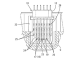
本発明の実施形態1を図1ないし図8によって説明する。この実施形態1では、自動車に搭載されるECU(電子制御ユニット)の基板Kに対して接続される基板用コネクタ10であって、コネクタハウジング11(以下、単にハウジング11という)の周りにECUのケースCが二次成形されるものを例示する。このハウジング11には、ケースC外から相手の雄コネクタ(図示せず)が嵌合可能とされる。なお以下では、ハウジング11における相手の雄コネクタとの嵌合面側を前方とし、その反対側を後方とし、また上下方向については図2などを基準とする。
<Embodiment 1>
A first embodiment of the present invention will be described with reference to FIGS. In the first embodiment, a
まず全体構造の概略を簡単に説明する。ケースCは、合成樹脂製とされ、図1に示すように、上面側が開口した浅い箱型に形成されるとともに、その開口側に基板Kが取り付けられるようになっている。この基板Kの下方位置であってケースCの底壁及び側壁には、基板用コネクタ10のハウジング11が埋設されている。
First, an outline of the overall structure will be briefly described. The case C is made of a synthetic resin, and as shown in FIG. 1, the case C is formed in a shallow box shape having an upper surface opened, and a substrate K is attached to the opening. The
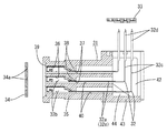
基板用コネクタ10は、図2に示すように、合成樹脂製のハウジング11と、ハウジング11に保持される端子金具12と、ハウジング11に装着されるアライメントプレート13とから構成されている。ハウジング11には、端子金具12が後方へ突出した状態で保持可能な端子保持部14が備えられている。この端子保持部14は、本体部15と、本体部15の前面側に組み付けられる中継端子ホルダ16とに前後に分割されており、それに応じて端子金具12は、本体部15に装着される端子本体17と、中継端子ホルダ16に装着される中継端子18とに分けられている。ハウジング11のうち中継端子ホルダ16の前半部分は、ケースCの側面において外部に臨んで配されるとともにその周りがケースCの一部により取り囲まれており、この筒状部分Caとの間に相手の雄コネクタのフード部が嵌合可能とされる。またケースCの筒状部分Caの上部には、相手の雄コネクタを嵌合状態に保持するための片持ち状のロックアームCbが形成されている。
As shown in FIG. 2, the
本体部15は、略ブロック状に形成されるとともに、前方から端子本体17を挿入可能な端子挿入孔19が前後に貫通して設けられている。端子挿入孔19は、上下4段、幅方向に6個(最上段のみ4個)並列配置されており、その孔縁前端部には端子本体17の挿入を案内可能なテーパ面が形成されている。端子本体17は、細長い板材を途中で上方(開口部側)へ向けてほぼ直角に屈曲させることで全体が略L字型に形成されており、言い換えると前後方向(ケースCの底壁)に沿った水平部分17aと、上下方向に沿った垂直部分17bとを連結した構成とされる。端子本体17のうち垂直部分17bの上端部が、基板Kの孔部内に挿入されるとともに半田付けされることで基板Kの導電路に対して接続可能な基板側接続部17cとされる。一方、水平部分17aの前端部(本体部15から前方へ突出する部分)が続いて説明する中継端子18と接続可能な中継端子側接続部17dとされる。各端子本体17における基板側接続部17cの上端位置と、中継端子側接続部17dの前端位置とは、それぞれほぼ同じに揃えられており、下段側の端子本体17ほど水平部分17a及び垂直部分17bの長さ寸法が大きくなり、且つ屈曲位置が後ろ寄りになっている。また本体部15の前端部は、中継端子ホルダ16側の形状に合わせて段付き状に縮径されている。
The
中継端子ホルダ16は、略ブロック状に形成されるとともに、その後端部には、本体部15の前端部に対して外嵌される嵌合筒部20が後方へ突出して設けられている。この中継端子ホルダ16内には、後方から中継端子18を収容可能な端子収容室21が後方へ開口して形成されている。端子収容室21は、上記本体部15の各端子挿入孔19と適合する位置にそれぞれ設けられるとともに、その前壁には相手の雄コネクタの相手雄端子が進入可能な挿通孔21aが開口形成されている。中継端子18は、一対の接続部18aを前後に連結した構成とされ、全体が前後対称形状となっているので、前後いずれも向きでも端子収容室21内に収容可能とされる。両接続部18aは、前後に開口する略箱型に形成されるとともにその内部には、端子本体17の中継端子側接続部17dや相手雄端子に対して弾性接触可能な片持ち状の弾性接触片18bが設けられている。端子収容室21内に収容された状態では、前側に配される接続部18aが相手雄端子に対して、後側に配される接続部18aが端子本体17に対して接続されるようになっている。
The
本体部15の後面両側縁からは、各端子本体17における後方への突出部分を両側から覆う一対の側壁22が後方へ延出して設けられている。両側壁22の上端部間には、各端子本体17の基板側接続部17cを整列するためのアライメントプレート13が保持可能とされている。アライメントプレート13は、各端子本体17の基板側接続部17cを挿通してこれらを位置決め可能な位置決め孔13aが、基板Kの各孔部に対応する位置に並んで設けられている。両側壁22は、最下段の端子本体17の後端部よりも後方位置に達しており、その後端面及び上端面には、ケースCを二次成形する際に用いられる金型Mが当接可能とされる。
A pair of
本体部15の後面下端部からは、各端子本体17における後方への突出部分を下側(ケースCの開口部とは反対側)から覆う壁部23が後方へ延出して設けられており、この壁部23により両側壁22の下端部同士が連結されている。壁部23は、両側壁22よりもさらに後方位置に達する長さを有しており、その後端部における上端面及び後端面がケースCを二次成形する際に用いられる金型Mが当接可能とされている。このように二次成形時には、両側壁22及び壁部23の端面がほぼ全周にわたって金型Mにより保持されるので、両側壁22及び壁部23により囲まれた空間S内に溶融状態の樹脂材が流入することが防がれるようになっている。従って、各端子本体17のうち上記空間S内に配される部分(本体部15から後方へ突出する部分)については、その周りがケースCの樹脂材に覆われることがなく、自由に弾性変形可能とされる。
From the lower end portion of the rear surface of the
本体部15の後面には、図2及び図3に示すように、上記した壁部23の上面に連結されることで壁部23を補強する補強壁24が設けられている。補強壁24は、側方から見て略三角形の梁状をなしており、幅方向に並ぶ各端子挿入孔19同士を仕切る位置に計5枚配設されている。従って、端子本体17を各端子挿入孔19内に挿入したり屈曲させる際に、各補強壁24によって端子本体17のうち上記空間S内に配される部分を整列させることができる。
As shown in FIGS. 2 and 3, a reinforcing
さて、本体部15における各端子挿入孔19の周縁部には、図2ないし図4に示すように、端子本体17における水平部分17aがその軸線方向と交差する方向へ変位するのを許容する変位許容凹部25が後方へ開口する形態でそれぞれ設けられている。詳しくは、各変位許容凹部25は、本体部15の前後の長さ寸法の約2/3程度の深さを有しており、端子挿入孔19内に配される端子本体17の水平部分17aは、前側の部分(本体部15の前後の長さ寸法の約1/3程度)が端子挿入孔19の周縁部により緊密に支持されるのに対し、その後側の部分については、変位許容凹部25により周りが除肉されているので、上下方向や幅方向へ凹部の径寸法の範囲内で自由に弾性変形できるようになっている。これにより、例えば基板Kとハウジング11との熱膨張率の相違によって両者間に位置ずれが生じた場合にそれに伴って端子本体17に対して作用する衝撃を吸収できるようになっている。なお最上段の端子挿入孔19に設けた変位許容凹部25は、その上部の深さが下部の半分程度に設定されている。
Now, as shown in FIGS. 2 to 4, the peripheral portion of each
変位許容凹部25は、後方から見て端子挿入孔19の外形に沿って略四角形に形成されるとともに、隣り合う変位許容凹部25同士が独立した形態とされているので、各変位許容凹部25の周りには略格子状をなす補強部26が残されている。これにより、変位許容凹部25を形成することに伴う本体部15の強度低下を抑制することができる。また各変位許容凹部25の周面のうち幅方向の側面は、補強壁24の側面とほぼ面一状に設定されている。
The
本実施形態は以上のような構造であり、続いてその作用を説明する。図5に示す状態から、本体部15の各端子挿入孔19内に、前後方向に沿ってほぼ真っ直ぐな状態の端子本体17を前方から挿入する。各端子本体17の中継端子側接続部17dの前端位置が揃う深さまで挿入したところで、図6に示すように、本体部15から後方へ突出した部分を治具などにより上方へほぼ直角に屈曲させる。その後、両側壁22の上端部間にアライメントプレート13を組み付けると、各端子本体17の基板側接続部17cが対応する位置決め孔13a内に挿通されることで、各基板側接続部17cが基板Kの各孔部に対して位置決めされる(図7)。
This embodiment has the structure as described above, and the operation thereof will be described subsequently. From the state shown in FIG. 5, the
その一方、中継端子ホルダ16の各端子収容室21内にそれぞれ中継端子18を後方から収容しておく。このとき、中継端子18は、前後対称形状となっているので、前後いずれの向きでも収容することができ、作業性が良好なものとなっている。そして、本体部15の前端部に対して中継端子ホルダ16の嵌合筒部20を外嵌させるよう組み付けると、図7に示すように、それに伴って各中継端子18の後側の接続部18a内に各端子本体17の中継端子側接続部17dが進入するとともに弾性接触片18bが弾性接触される。なお本体部15の前端部に対して中継端子ホルダ16の嵌合筒部20が圧入気味に嵌合することで、両者が組み付け状態に保持される。
On the other hand, the
上記のようにして基板用コネクタ10を組み付けた後、ハウジング11の周りにケースCを二次成形する作業を行う。図8に示すように、基板用コネクタ10を二次成形用の金型M内にセットする。ハウジング11は、上方・下方・側方へそれぞれ型開きされる3つの金型Mにより保持されており、特に上方(ケースCの開口方向)へ向けて型開きされる金型Mによって両側壁22及び壁部23の各端面がほぼ全周にわたって保持される。従って、その後金型Mの樹脂充填空間内に溶融状態の樹脂材を充填しても、両側壁22や壁部23に囲まれた空間内には、樹脂材が侵入することが防がれるようになっている。この樹脂材充填時には、樹脂充填空間に臨むハウジング11の周面に対して樹脂材の射出圧が作用することになるが、変位許容凹部25を設けた本体部15には補強部26が残されることで十分な強度が保たれているので、射出圧により本体部15が変形などすることが防がれるようになっている。同様に壁部23にも樹脂材の射出圧が作用することになるが、梁状の補強壁24によって補強されているので、射出圧により変形などすることが防がれる。
After assembling the
樹脂材が冷却・固化したところで型開きすると、図2に示すように、ハウジング11の周りにケースCが二次成形されたものが取り出される。その後、ケースCの開口部側に基板Kを取り付けて、各孔部に挿通した各端子本体17の基板側接続部17cを半田付けすることで、各基板側接続部17cが対応する導電路に対して電気的に接続される。それから、ケースC外から相手の雄コネクタを基板用コネクタ10の嵌合部分に嵌合すると、相手雄端子が中継端子18の前側の接続部18aに対して接続される。これにより、相手雄端子が中継端子18を介して、基板Kに接続された端子本体17に対して電気的に接続される。
When the mold is opened when the resin material is cooled and solidified, as shown in FIG. 2, the case C is secondarily molded around the
上記のようにして組み付けが完了したら、自動車に搭載されて使用されることになるが、例えば高温環境下ではハウジング11をなす樹脂材と基板Kをなす樹脂材との熱膨張率の相違により、両者間で位置ずれが発生する場合がある。その場合でも、端子本体17のうち本体部15から後方へ突出した部分が周りの空間に逃がされつつ弾性変形することで、位置ずれに伴って端子本体17に作用する衝撃を吸収することができる。しかもこのとき、端子本体17のうち本体部15内に配される水平部分17aが変位許容凹部25内に逃がされつつ弾性変形することで、上記衝撃を吸収することができるので、衝撃吸収性能が高められている。
When the assembly is completed as described above, it will be mounted and used in an automobile. For example, in a high temperature environment, due to the difference in thermal expansion coefficient between the resin material forming the
以上説明したように本実施形態によれば、本体部15(端子保持部14)における端子本体17(端子金具12)の周りに、端子本体17がその軸線方向と交差する方向へ変位するのを許容する変位許容凹部25を設けるようにし、且つこの変位許容凹部25が本体部15の強度を保つための補強部26を残す形態とされているから、全体の大型化や本体部15の強度低下を招くことなく、衝撃吸収性能を高めることができる。
As described above, according to the present embodiment, the
しかも、ハウジング11の周りにケースCを二次成形する場合でも、本体部15の強度が十分得られているので、二次成形時に金型M内に充填される樹脂材の射出圧によって本体部15が変形などすることが防がれる。さらには、二次成形時に金型Mによって保持される壁部23を補強するための補強壁24が設けられているから、二次成形に一層好適となる。
Moreover, even when the case C is secondarily molded around the
<参考例>
参考例を図9ないし図12によって説明する。この参考例では、実施形態1の中継端子などを省略したものを示す。
< Reference example >
Reference examples will be described with reference to FIGS. In this reference example , the relay terminal of Embodiment 1 is omitted.
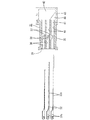
基板用コネクタ30は、図9に示すように、端子保持部35などを備えたハウジング31と、ハウジング31に保持される端子金具32と、ハウジング31に装着されるアライメントプレート33及び抜け止め部材34とから構成される。端子金具32は、途中で屈曲した略L字型をなす板状部32aと、その前端側に連結された略箱型をなす接続部32bとから構成されている。接続部32bは、前後に開口するとともに内部に相手雄端子に対して弾性接触可能な弾性接触片(図示せず)を備えている。また板状部32aのうち垂直部分32cの上端部は、基板Kに対して接続される基板側接続部32dとされる。ハウジング31の端子保持部35には、端子金具32のうち接続部32bが収容される収容室36と、板状部32aが挿入される挿入孔37とが前後に並ぶとともに互いに連通する形態で形成され、上下3段、幅方向に複数個ずつ並んで配されている。収容室36の後端部には、接続部32bの後端部に突き当たることで、端子金具32の挿入深さを規制可能な規制部38が設けられている。端子保持部35の前面には、収容した端子金具32を抜け止めするための抜け止め部材34を装着可能な装着凹部39が形成されている。抜け止め部材34は、装着凹部39に内嵌可能な略板状に形成されるとともに、相手雄端子の進入を許容する挿通孔34aが各収容室36に対応した位置に貫通形成されている。この抜け止め部材34は、振動溶着などにより端子保持部35に対して固定される。
As shown in FIG. 9, the
さて、端子保持部35のうち各挿入孔37の周縁部には、端子金具32における板状部32aの水平部分32eがその軸線方向と交差する方向へ変位するのを許容する変位許容凹部40が後方へ開口する形態でそれぞれ設けられている。変位許容凹部40は、端子保持部35の前後の長さ寸法の約半分程度の深さを有しており、挿入孔37内に配される板状部32aの水平部分32eは、前端部のみが挿入孔37の周縁部により緊密に支持されるのに対し、その後側の部分については、上下方向や幅方向へ凹部の径寸法の範囲内で自由に弾性変形可能とされる。この変位許容凹部40は、水平部分32eに対して上側部分よりも下側部分の方が径寸法が大きく設定されている。端子保持部35のうち各変位許容凹部40の周りには、略格子状をなす補強部41が残されているので、端子保持部35の強度を十分に保つことができる。なお端子保持部35の後面には、実施形態1と同様に一対の側壁42、壁部43及び補強壁44が設けられているが、その構造や機能については実施形態1と同様であるため、詳しい説明は割愛するものとする。またアライメントプレート33についても同様に詳しい説明は省略する。
Now, at the periphery of each
続いて組付方法について説明する。図10に示す状態から、端子保持部35の収容室36及び挿入孔37内に端子金具32のうち真っ直ぐな形態とした板状部32aを挿入する。端子金具32が正規深さに達し、収容室36内に収容された接続部32bの後端部が規制部38に突き当たったところで、図11に示すように、治具などを用いて板状部32aを曲げ加工する。その後、図12に示すように、両側壁42間にアライメントプレート33を装着して基板側接続部32dを整列させるとともに、抜け止め部材34を装着凹部39内に嵌合し、振動溶着などにより固定することで端子金具32の前方への抜け止めを図る。上記のようにして組み付けた基板用コネクタ30を二次成形用の金型内にセットし、ハウジング31の周りにケースCを二次成形する。その後、図9に示すように、基板Kを取り付けて各基板側接続部32dを半田付けしてから、端子保持部35の前端部に相手の雄コネクタを嵌合する。
Next, the assembly method will be described. From the state shown in FIG. 10, the straight plate-
<他の実施形態>
本発明は上記記述及び図面によって説明した実施形態に限定されるものではなく、例えば次のような実施形態も本発明の技術的範囲に含まれ、さらに、下記以外にも要旨を逸脱しない範囲内で種々変更して実施することができる。
(1)上記した実施形態では、端子保持部における端子金具の周りを除肉した変位許容凹部を例示したが、例えば端子金具の周りにその変位を許容する弾性部材を設けることで変位許容領域を構成したものも本発明に含まれる。
<Other embodiments>
The present invention is not limited to the embodiments described with reference to the above description and drawings. For example, the following embodiments are also included in the technical scope of the present invention, and further, within the scope not departing from the gist of the invention other than the following. Various modifications can be made.
(1) In the above-described embodiment, the displacement-permissible concave portion in which the periphery of the terminal fitting in the terminal holding portion is thinned is illustrated. However, for example, the displacement-permissible region is provided by providing an elastic member that allows the displacement around the terminal fitting. What was comprised is also contained in this invention.
(2)上記した実施形態では、端子保持部に一対の側壁を設けたものを示したが、側壁を省略してもよい。その場合でも、二次成形時に金型にて壁部の端面を適宜に保持することで、その内側の空間に樹脂材が流入するのを防ぐことができる。またアライメントプレートを備えないものにも本発明は適用可能である。 (2) In the above-described embodiment, the terminal holding portion is provided with a pair of side walls, but the side walls may be omitted. Even in such a case, it is possible to prevent the resin material from flowing into the inner space by appropriately holding the end face of the wall portion with the mold during the secondary molding . Present invention is also applicable to those having no or alignment plate is applicable.
(3)端子金具については、途中で屈曲されないストレートタイプのものも本発明に適用可能である。また端子金具の本数やハウジングに対する配置については任意に変更可能である。
(4)上記した実施形態では、相手の雄コネクタと嵌合される基板用コネクタ(嵌合部分が雌型のもの)を示したが、相手の雌コネクタと嵌合される基板用コネクタ(嵌合部分が雄型のもの)にも本発明は適用可能である。
(3) About a terminal metal fitting, the straight type thing which is not bent in the middle is applicable to the present invention. The number of terminal fittings and the arrangement with respect to the housing can be arbitrarily changed.
(4) In the above-described embodiment, the board connector (fitting portion is female) fitted to the mating male connector is shown. However, the board connector (fitting) fitted to the mating female connector is shown. The present invention can also be applied to a male part).
10,30…基板用コネクタ
11,31…ハウジング
12,32…端子金具
14,35…端子保持部
15…本体部
16…中継端子ホルダ
17…端子本体
18…中継端子
18a…接続部
23,43…壁部
24,44…補強壁
25,40…変位許容凹部(変位許容領域)
26,41…補強部
C…ケース(二次成形部)
K…基板
M…金型
DESCRIPTION OF
26, 41 ... reinforcement part C ... case (secondary molding part)
K ... Substrate M ... Mold
Claims (2)
前記端子保持部における端子金具の周りには、端子金具がその軸線方向と交差する二方向へ自由に弾性変形することを許容する変位許容領域が設けられ、この変位許容領域は、端子保持部の強度を保つための補強部を有し、その補強部は前記変位許容領域が各端子金具毎に互いに独立した形態となるよう、略格子状をなしており、
前記コネクタハウジングの周りには、二次成形部が二次成形され、且つ前記二次成形部は、前記端子保持部のうち少なくとも前記補強部の周面を覆う形態とされ、
前記端子保持部は、本体部と、嵌合筒部を有しその嵌合筒部が前記本体部の前面側に嵌合して組み付けられる中継端子用ホルダとから構成されるとともに、前記端子金具は、前記本体部に後方へ突出した状態で装着される端子本体と、前記中継端子ホルダに装着される中継端子とから構成されており、
前記中継端子は、前後に一対の接続部を有しており、このうち後側の接続部が前記中継端子ホルダを前記本体部に組み付けるのに伴って前記端子本体に接続され、前側の接続部が前記コネクタハウジングに対して嵌合される相手コネクタと接続されるようになっていることを特徴とする基板用コネクタ。 The connector housing is provided with a terminal holding portion capable of holding the terminal fitting in a state of protruding backward, and the end portion of the protruding portion of the terminal fitting is connected to the substrate.
Around the terminal fitting in the terminal holding portion, there is provided a displacement permissible region that allows the terminal fitting to be elastically deformed freely in two directions intersecting the axial direction. It has a reinforcing part for maintaining the strength, and the reinforcing part has a substantially lattice shape so that the displacement permissible area is independent from each other for each terminal fitting ,
Around the connector housing, the secondary molded part is post-forming,且 one said secondary molding unit is a cover the peripheral surface of at least the reinforcing portion of the terminal holding portion,
The terminal holding portion includes a main body portion and a relay terminal holder that has a fitting cylinder portion and the fitting cylinder portion is fitted and assembled to the front side of the main body portion. Is composed of a terminal main body mounted in a state protruding rearward from the main body, and a relay terminal mounted on the relay terminal holder,
The relay terminal has a pair of front and rear connection portions, of which the rear connection portion is connected to the terminal body as the relay terminal holder is assembled to the main body portion, and the front connection portion. Is connected to a mating connector fitted to the connector housing .
Priority Applications (4)
| Application Number | Priority Date | Filing Date | Title |
|---|---|---|---|
| JP2004211855A JP4356548B2 (en) | 2004-07-20 | 2004-07-20 | Board connector |
| DE102005032950A DE102005032950B4 (en) | 2004-07-20 | 2005-07-14 | Connector and method for its formation |
| US11/185,639 US7278862B2 (en) | 2004-07-20 | 2005-07-19 | Connector |
| CNB2005100860070A CN100463296C (en) | 2004-07-20 | 2005-07-20 | Connector and manufacturing method thereof |
Applications Claiming Priority (1)
| Application Number | Priority Date | Filing Date | Title |
|---|---|---|---|
| JP2004211855A JP4356548B2 (en) | 2004-07-20 | 2004-07-20 | Board connector |
Publications (2)
| Publication Number | Publication Date |
|---|---|
| JP2006032218A JP2006032218A (en) | 2006-02-02 |
| JP4356548B2 true JP4356548B2 (en) | 2009-11-04 |
Family
ID=35657818
Family Applications (1)
| Application Number | Title | Priority Date | Filing Date |
|---|---|---|---|
| JP2004211855A Active JP4356548B2 (en) | 2004-07-20 | 2004-07-20 | Board connector |
Country Status (4)
| Country | Link |
|---|---|
| US (1) | US7278862B2 (en) |
| JP (1) | JP4356548B2 (en) |
| CN (1) | CN100463296C (en) |
| DE (1) | DE102005032950B4 (en) |
Families Citing this family (22)
| Publication number | Priority date | Publication date | Assignee | Title |
|---|---|---|---|---|
| JP4742877B2 (en) * | 2006-01-18 | 2011-08-10 | 住友電装株式会社 | Molded structure of resin molded product |
| FR2899375A1 (en) * | 2006-04-04 | 2007-10-05 | Peugeot Citroen Automobiles Sa | Multichannel fixed connector for motor vehicle, has adherent sealing material incorporated in connection zone connecting tabs with printed circuit board so as to seal zone from line, and rear part engaged inside distribution case |
| FR2903236B1 (en) * | 2006-06-30 | 2008-10-03 | Valeo Sys Controle Moteur Sas | ELECTRONIC CARD WITH A TWO-PART CONNECTOR AND METHOD FOR MANUFACTURING SUCH A CARD |
| JP4356768B2 (en) * | 2007-05-18 | 2009-11-04 | 株式会社デンソー | Electronic device and molding die thereof |
| CN201054405Y (en) * | 2007-05-22 | 2008-04-30 | 富士康(昆山)电脑接插件有限公司 | Electric connector |
| US7491096B1 (en) * | 2007-07-31 | 2009-02-17 | Phoenix Contact Development & Manufacturing Inc. | Modular terminal block |
| JP4863954B2 (en) * | 2007-09-10 | 2012-01-25 | 新電元工業株式会社 | Electronic unit and manufacturing method thereof |
| US7455552B1 (en) * | 2008-02-06 | 2008-11-25 | Delphi Technologies, Inc. | Overmolded electronic assembly with metal seal ring |
| WO2010001450A1 (en) * | 2008-06-30 | 2010-01-07 | 富士通株式会社 | Connector, substrate comprising the same, and electronic device |
| JP5590386B2 (en) * | 2010-06-03 | 2014-09-17 | 住友電装株式会社 | Connector and connector manufacturing method |
| JP5397338B2 (en) * | 2010-07-21 | 2014-01-22 | 住友電装株式会社 | Connector manufacturing method |
| JP5605156B2 (en) | 2010-10-18 | 2014-10-15 | 住友電装株式会社 | Case integrated connector |
| DE102011006195A1 (en) | 2011-03-28 | 2012-10-04 | Robert Bosch Gmbh | Modular electrical connector assembly |
| JP2013089387A (en) | 2011-10-14 | 2013-05-13 | Yazaki Corp | Terminal and connector |
| DE102012001478A1 (en) | 2012-01-26 | 2013-08-01 | Wabco Gmbh | Method for producing a control unit housing and a control unit housing produced by this method |
| PL2634877T3 (en) * | 2012-02-28 | 2015-12-31 | Wilo Salmson France | Method for manufacturing a control housing for a circulation pump |
| JP5525574B2 (en) * | 2012-08-07 | 2014-06-18 | ホシデン株式会社 | Component module and component module manufacturing method |
| JP5965789B2 (en) * | 2012-08-31 | 2016-08-10 | 矢崎総業株式会社 | connector |
| DE102013206095B4 (en) * | 2013-04-05 | 2020-10-01 | Lenze Automation Gmbh | Adapter for connecting to connection contacts of an electrical control device |
| US10700462B2 (en) | 2018-01-18 | 2020-06-30 | Interplex Industries, Inc. | Connector housing |
| WO2020009925A1 (en) * | 2018-07-01 | 2020-01-09 | Interplex Industries, Inc. | Connector housing and method of manufacturing same |
| JP7081549B2 (en) * | 2019-03-27 | 2022-06-07 | 株式会社オートネットワーク技術研究所 | connector |
Family Cites Families (7)
| Publication number | Priority date | Publication date | Assignee | Title |
|---|---|---|---|---|
| US5215471A (en) * | 1989-06-13 | 1993-06-01 | General Datacomm, Inc. | Electrical connectors having tapered spring contact elements for direct mating to holes |
| JP2752024B2 (en) * | 1992-03-25 | 1998-05-18 | 矢崎総業株式会社 | Printed circuit board connector |
| JP3404832B2 (en) | 1993-10-15 | 2003-05-12 | 住友電装株式会社 | Method of manufacturing connector and connector |
| NL9302227A (en) * | 1993-12-21 | 1995-07-17 | Connector Systems Tech Nv | Electrical connector with a body positioning the connection pins. |
| US5382169A (en) | 1994-01-14 | 1995-01-17 | Labinal Components And Systems, Inc. | Electrical connectors |
| US6256572B1 (en) | 1999-03-30 | 2001-07-03 | Kelsey-Hayes Company | Remote programming of an ABS electronic control module |
| JP3997852B2 (en) | 2002-06-28 | 2007-10-24 | 住友電装株式会社 | Insert molded connector |
-
2004
- 2004-07-20 JP JP2004211855A patent/JP4356548B2/en active Active
-
2005
- 2005-07-14 DE DE102005032950A patent/DE102005032950B4/en active Active
- 2005-07-19 US US11/185,639 patent/US7278862B2/en active Active
- 2005-07-20 CN CNB2005100860070A patent/CN100463296C/en active Active
Also Published As
| Publication number | Publication date |
|---|---|
| JP2006032218A (en) | 2006-02-02 |
| DE102005032950B4 (en) | 2009-02-05 |
| CN100463296C (en) | 2009-02-18 |
| US7278862B2 (en) | 2007-10-09 |
| DE102005032950A1 (en) | 2006-02-23 |
| CN1761108A (en) | 2006-04-19 |
| US20060019516A1 (en) | 2006-01-26 |
Similar Documents
| Publication | Publication Date | Title |
|---|---|---|
| JP4356548B2 (en) | Board connector | |
| CN110582896B (en) | Connector for substrate | |
| JP5397338B2 (en) | Connector manufacturing method | |
| JP5238481B2 (en) | Electrical connector | |
| JP6244345B2 (en) | connector | |
| JP2010040183A (en) | Connector | |
| JP4470116B2 (en) | Molded structure of case with connector | |
| JP4782024B2 (en) | Electronic junction box and its assembly method | |
| CN112236905B (en) | Circuit board device and connector for substrate | |
| JP2014194854A (en) | Case integrated connector and method of manufacturing the same | |
| US20230065611A1 (en) | Connector | |
| JP2013033633A (en) | Connector | |
| US7819695B2 (en) | Multi-unit connector | |
| CN112335134B (en) | Circuit board device | |
| JP2010212196A (en) | Electronic device | |
| JP2005044586A (en) | Plug for electrical connection | |
| JP4862612B2 (en) | Connector and mold for molding | |
| JP4356590B2 (en) | Assembly structure of terminal bracket and alignment plate in board connector | |
| WO2024005061A1 (en) | Connector | |
| JP2019175728A (en) | connector | |
| JP6032109B2 (en) | Board connector and case integrated connector | |
| JP2002184511A (en) | Connector | |
| JP2006351330A (en) | Connector with integrated case | |
| JP2024005523A (en) | connector | |
| JP2014211979A (en) | Connector for substrate and case-integrated connector |
Legal Events
| Date | Code | Title | Description |
|---|---|---|---|
| RD04 | Notification of resignation of power of attorney |
Free format text: JAPANESE INTERMEDIATE CODE: A7424 Effective date: 20061025 |
|
| A621 | Written request for application examination |
Free format text: JAPANESE INTERMEDIATE CODE: A621 Effective date: 20070115 |
|
| A977 | Report on retrieval |
Free format text: JAPANESE INTERMEDIATE CODE: A971007 Effective date: 20081211 |
|
| A131 | Notification of reasons for refusal |
Free format text: JAPANESE INTERMEDIATE CODE: A131 Effective date: 20081222 |
|
| A521 | Request for written amendment filed |
Free format text: JAPANESE INTERMEDIATE CODE: A523 Effective date: 20090209 |
|
| A131 | Notification of reasons for refusal |
Free format text: JAPANESE INTERMEDIATE CODE: A131 Effective date: 20090407 |
|
| A521 | Request for written amendment filed |
Free format text: JAPANESE INTERMEDIATE CODE: A523 Effective date: 20090608 |
|
| TRDD | Decision of grant or rejection written | ||
| A01 | Written decision to grant a patent or to grant a registration (utility model) |
Free format text: JAPANESE INTERMEDIATE CODE: A01 Effective date: 20090714 |
|
| A01 | Written decision to grant a patent or to grant a registration (utility model) |
Free format text: JAPANESE INTERMEDIATE CODE: A01 |
|
| A61 | First payment of annual fees (during grant procedure) |
Free format text: JAPANESE INTERMEDIATE CODE: A61 Effective date: 20090727 |
|
| FPAY | Renewal fee payment (event date is renewal date of database) |
Free format text: PAYMENT UNTIL: 20120814 Year of fee payment: 3 |
|
| R150 | Certificate of patent or registration of utility model |
Ref document number: 4356548 Country of ref document: JP Free format text: JAPANESE INTERMEDIATE CODE: R150 Free format text: JAPANESE INTERMEDIATE CODE: R150 |
|
| FPAY | Renewal fee payment (event date is renewal date of database) |
Free format text: PAYMENT UNTIL: 20120814 Year of fee payment: 3 |
|
| FPAY | Renewal fee payment (event date is renewal date of database) |
Free format text: PAYMENT UNTIL: 20130814 Year of fee payment: 4 |