【0001】
【発明の属する技術分野】
本発明は印刷装置に関し、詳しくは1工程で用紙の両面に印刷を行うことが可能な両面印刷装置の構造に関する。
【0002】
【従来の技術】
従来、簡便な印刷方法としてデジタル式感熱孔版印刷が知られている。この孔版印刷装置は、微細な発熱素子が一列に配置されたサーマルヘッドを感熱孔版マスタ(以下、「マスタ」という)に接触させ、パルス的に発熱素子に通電させながらマスタを搬送することで画像情報に応じてマスタを加熱溶融穿孔し、このマスタを多孔性円筒状の版胴の外周面に巻装した後に用紙を介して版胴の外周面をプレスローラー等の押圧手段によって押圧することで、マスタ穿孔部よりインキを透過させてこれを用紙に転移させることにより印刷画像を得るものである。
【0003】
この孔版印刷において、近年では用紙の消費量及び書類の保管スペースを低減させるため等の目的から、用紙の両面に印刷を行う両面印刷が頻繁に行われるようになってきている。この両面印刷は、従来の方法では給紙部に積載した用紙を印刷部に通紙し、一面に印刷をした後に用紙を裏返して再度印刷部に通紙して他面に印刷をすることで両面印刷物を得ていたが、一度排紙された用紙を再度給紙部にセットしたり片面印刷後の用紙を揃えたりする作業が面倒であるという問題点があった。
【0004】
また、印刷終了後の印刷物はインキが十分に乾燥していないため、すぐに裏面に印刷しようとすると搬送ローラーやプレスローラー等が画像部に押し付けられて印刷画像が汚れたり乱れたりするという不具合が生じ、大抵の場合には数時間以上経過してから裏面への印刷を行っていた。特に、ベタ画像部がある場合には長時間の乾燥が必要であり、翌日になってから裏面への印刷が行われていた。
このように両面印刷は、一面印刷後に他面に印刷を行うまでには用紙を長時間乾燥させねばならず、しかも印刷部への通紙を2回行うために正味の印刷時間においても片面印刷に比べて2倍の時間を要し、時間がかかりすぎるという問題点があった。
【0005】
上述の問題点を解決するため、第1の版胴と、用紙搬送路を介して第1の版胴と対向配置された第2の版胴と、第1の版胴の外周面と第2の版胴の外周面とを互いに接離させる接離手段とを具備し、接離手段を作動させて各版胴同士を互いに圧接させることにより1工程で両面印刷物を得る孔版印刷装置が特開平6−71996号公報及び特開平6−135111号公報に開示されている。
【0006】
また、第1の版胴と、用紙搬送路を介して第1の版胴に対向配置され第1の版胴に対して圧接・離間可能に設けられた第1の押圧手段と、第1の版胴より用紙搬送方向下流側であって用紙搬送路を介して第1の版胴と対向する側に配置された第2の版胴と、用紙搬送路を介して第2の版胴に対向配置され第2の版胴に対して圧接・離間可能に設けられた第2の押圧手段とを具備し、第1の版胴と第1の押圧手段とを圧接させた後、第2の版胴と第2の押圧手段とを圧接させることにより1工程で両面印刷物を得る孔版印刷装置が特開平8−90893号公報及び特開平8−142477号公報に開示されている。
【0007】
さらに、版胴の回転方向に第1製版画像と第2製版画像とが2面並んだ分割製版済みマスタを用い、何れか一方の製版画像の画像領域と対応させてプレスローラーを版胴に直接当接させつつ版胴と共に回転させてプレスローラーの外周面に一方の製版画像と対応する第1印刷画像を転写する第1工程と、第1工程後に他方の製版画像の画像領域と第1印刷画像とが対応すべく、用紙を介してプレスローラーを版胴に当接させつつ版胴と共に回転させて用紙のプレスローラーと対応する第1の面に第1印刷画像を再転写させると同時に、用紙の版胴と対応する第2の面に他方の製版画像と対応する第2印刷画像を転写させる第2工程とにより1工程で両面印刷物を得る孔版印刷方法、及びこれを行う孔版印刷装置が特開平8−332768号公報に開示されている。
【0008】
【発明が解決しようとする課題】
しかし、特開平6−71996号公報及び特開平6−135111号公報に開示された技術では、2個の版胴を上下に配置してこれらを互いに圧接させる構成であるため片面印刷時においても各版胴同士を圧接させる必要があり、一方の版胴には製版済みマスタを、他方の版胴には未製版のマスタをそれぞれ巻装しなくてはならず、片面印刷時にはマスタが無駄に消費されてしまうという問題点がある。また、外周面上にマスタを保持するためのクランパーをそれぞれ有する2個の版胴を互いに圧接させるために各クランパーが向かい合う位置では各版胴を離隔させる必要が生じ、印刷速度が速くなるとこの離隔によって互いの版胴が接触する面積が減少して画像量域が減少するため、画像量域を確保するためには各版胴の外径を大きくする必要が生じて装置の小型化が困難となると共に、各版胴の接触時において大きな騒音が発生するという問題点がある。
【0009】
特開平8−90893号公報及び特開平8−142477号公報に開示された技術では、上述と同様に片面印刷時において一方の版胴に未製版のマスタを巻装する必要があり、マスタが無駄に消費されてしまうという問題点がある。また、用紙搬送方向に2個の版胴を直列に並べているため、片面印刷用の孔版印刷装置に比して装置が2倍近くも大きくなり、その設置スペースの確保が困難になるという問題点がある。
【0010】
特開平8−332768号公報に開示された技術では、第1製版画像及び第2製版画像(表面画像及び裏面画像)のうちの何れか一方を版胴から用紙に直接転写させ、他方をプレスローラーに転写させた後に用紙に再転写させているため、用紙上における画像濃度が表面と裏面とで異なってしまうという問題点がある。
【0011】
本発明は上述の問題点を解決し、無駄なマスタを用いることなく片面印刷を行うことができると共に両面印刷時には画質良好な印刷物を得ることができ、さらに設置スペースの増大を抑制することが可能な1工程両面印刷装置の提供を目的とする。
【0012】
【課題を解決するための手段】
請求項1記載の発明は、その長さ方向に第1製版画像と第2製版画像とが2面並んだ分割製版済みマスタを外周面上に巻装する版胴及び前記版胴に対して接離自在に設けられたプレスローラーを有する印刷部と、用紙を前記印刷部に向けて給送する給紙部と、前記印刷部において印刷がなされた印刷済み用紙を機外に排出する排紙部と、前記印刷部においてその表面に印刷画像を形成された表面印刷済み用紙を一時的に貯容する補助トレイと、前記補助トレイ上に貯容された表面印刷済み用紙を前記プレスローラーの外周面に沿う態様で前記印刷部に向けて再給紙する再給紙手段と、前記印刷部を通過した用紙を前記補助トレイまたは前記排紙部の何れかに案内する切換部材とを有し、両面印刷時に、前記給紙部より1枚目の用紙を前記印刷部に給送してその表面に第1製版画像または第2製版画像の何れか一方を印刷し、印刷された1枚目の用紙を前記切換部材により前記補助トレイに案内した後、前記給紙部より2枚目の用紙を前記印刷部に給送してその表面に第1製版画像または第2製版画像の何れか一方を印刷すると共に前記再給紙手段により1枚目の用紙を前記印刷部に再給紙してその裏面に第1製版画像または第2製版画像の何れか他方を印刷し、前記切換部材により1枚目の用紙を前記排紙部に、2枚目の用紙を前記補助トレイにそれぞれ案内し、前記再給紙手段は、前記補助トレイ上に貯容された表面印刷済み用紙を前記プレスローラーに向けて搬送する再給紙搬送部材と、前記再給紙搬送部材によって搬送された表面印刷済み用紙を前記プレスローラーの手前の所定位置で一時停止させる再給紙位置決め部材と、前記再給紙位置決め部材によって所定位置で一時停止された表面印刷済み用紙を所定のタイミングで回転中の前記プレスローラーに接触させる再給紙レジスト部材と、前記再給紙レジスト部材によって回転中の前記プレスローラーに接触され前記プレスローラーの回転力によって搬送される表面印刷済み用紙を前記プレスローラーの周面に当接させて前記版胴に向けて案内する再給紙案内部材とを有することを特徴とする。
【0015】
請求項2記載の発明は、請求項1記載の両面印刷装置において、さらに前記補助トレイは前記排紙部の下方に配設されていることを特徴とする。
【0016】
請求項3記載の発明は、請求項1または2記載の両面印刷装置において、さらに前記プレスローラーを回転自在に支持するプレスローラー支持部材と、前記プレスローラー支持部材を揺動させて前記プレスローラーを前記版胴に対して接離させるプレスローラー接離機構と、前記再給紙レジスト部材を支持する再給紙レジスト支持部材とを有し、前記再給紙レジスト支持部材が前記プレスローラー支持部材に揺動自在に設けられると共に前記再給紙レジスト支持部材を揺動させて前記再給紙レジスト部材を前記プレスローラーに対して接離させる再給紙レジスト接離機構を有することを特徴とする両面印刷装置。
【0017】
請求項4記載の発明は、請求項3記載の両面印刷装置において、さらに前記プレスローラー接離機構は、印刷開始直後の前記版胴の1回転目は第1製版画像または第2製版画像の何れか他方が前記プレスローラーの周面に接触しないように前記プレスローラーを前記版胴から離隔させると共に、印刷終了直前の前記版胴の最終回転目は第1製版画像または第2製版画像の何れか一方が前記プレスローラーの周面に接触しないように前記プレスローラーを前記版胴から離隔させることを特徴とする。
【0018】
請求項5記載の発明は、請求項1ないし4の何れか1つに記載の両面印刷装置において、さらに前記再給紙案内部材が前記プレスローラーに当接した回転自在なローラーからなり、前記ローラーが前記プレスローラー支持部材に回転自在に支持されていることを特徴とする。
【0019】
請求項6記載の発明は、請求項1ないし4の何れか1つに記載の両面印刷装置において、さらに前記再給紙案内部材が2個のローラー及び各ローラー間に掛け渡され前記プレスローラーに当接した無端ベルトからなり、前記各ローラーが前記プレスローラー支持部材に回転自在に支持されていることを特徴とする。
【0020】
請求項7記載の発明は、請求項1ないし4の何れか1つに記載の両面印刷装置において、さらに前記再給紙案内部材が前記プレスローラーに当接した板部材からなり、前記板部材が前記プレスローラー支持部材に支持されていることを特徴とする。
【0021】
請求項8記載の発明は、請求項1ないし7の何れか1つに記載の両面印刷装置において、さらに前記プレスローラーの周面をクリーニングするクリーニング部材を有することを特徴とする。
【0022】
請求項9記載の発明は、請求項8記載の両面印刷装置において、さらに前記クリーニング部材は前記プレスローラーの周面に対して接離自在に設けられていることを特徴とする。
【0023】
請求項10記載の発明は、請求項9記載の両面印刷装置において、さらに前記クリーニング部材は片面印刷時に前記プレスローラーの周面から離隔した位置を占めることを特徴とする。
【0024】
請求項11記載の発明は、請求項1ないし7の何れか1つに記載の両面印刷装置において、さらに前記プレスローラーがプレスローラー回転駆動手段により前記版胴の周速度とほぼ同じ周速度で回転駆動されることを特徴とする。
【0025】
請求項12記載の発明は、請求項11記載の両面印刷装置において、さらに前記プレスローラーは前記版胴との当接時に前記版胴からの回転力によって従動回転することを特徴とする。
【0026】
請求項13記載の発明は、請求項11または12記載の両面印刷装置において、さらに前記プレスローラー回転駆動手段は、前記プレスローラーの揺動時において前記プレスローラーの自転による位相の変化を防止する駆動力伝達手段を有することを特徴とする。
【0027】
請求項14記載の発明は、請求項13記載の両面印刷装置において、さらに前記プレスローラーの直径は前記版胴の直径の2分の1ないし3分の1の範囲内にあることを特徴とする。
【0028】
請求項15記載の発明は、請求項11ないし14の何れか1つに記載の両面印刷装置において、さらに前記プレスローラーの周面をクリーニングするクリーニング部材を有することを特徴とする。
【0029】
請求項16記載の発明は、請求項15記載の両面印刷装置において、さらに前記クリーニング部材は前記プレスローラーの周面に対して接離自在に設けられていることを特徴とする。
【0030】
請求項17記載の発明は、請求項16記載の両面印刷装置において、さらに前記クリーニング部材は片面印刷時に前記プレスローラーの周面から離隔した位置を占めることを特徴とする。
【0031】
請求項18記載の発明は、請求項16または17記載の両面印刷装置において、さらに前記クリーニング部材が前記再給紙レジスト部材と前記再給紙案内部材との間の位置に配置され、前記クリーニング部材は前記再給紙レジスト部材によって表面印刷済み用紙が搬送されている間は前記プレスローラーの周面から離隔した位置を占めることを特徴とする。
【0032】
請求項19載の発明は、請求項18記載の両面印刷装置において、さらに前記プレスローラーの周面長さが第1製版画像または第2製版画像の長さよりも長いことを特徴とする。
【0033】
請求項20記載の発明は、請求項1ないし19の何れか1つに記載の両面印刷装置において、さらに前記プレスローラーはその周面が撥インキ性を有することを特徴とする。
【0034】
請求項21記載の発明は、請求項1ないし20の何れか1つに記載の両面印刷装置において、さらに前記給紙部に厚紙がセットされた場合に警告を表示する第1表示手段を有することを特徴とする。
【0035】
請求項22記載の発明は、請求項1ないし21の何れか1つに記載の両面印刷装置において、さらに前記給紙部にセットされた用紙のサイズと第1製版画像及び第2製版画像の画像領域サイズとが不一致の場合に警告を発する第2表示手段を有することを特徴とする。
【0036】
請求項23記載の発明は、請求項1ないし22の何れか1つに記載の両面印刷装置において、さらに前記分割製版済みマスタを製版する製版部を有することを特徴とする。
【0037】
請求項24記載の発明は、請求項23記載の両面印刷装置において、さらに前記製版部は前記分割製版済みマスタを製版する際に第1製版画像と第2製版画像との間に所定の空白部を設けることを特徴とする。
【0038】
請求項25記載の発明は、請求項23または24記載の両面印刷装置において、さらに前記製版部は前記分割製版済みマスタを製版する際にべた部の多い画像を用紙の裏面側に印刷される製版画像として製版することを特徴とする。
【0039】
請求項26記載の発明は、請求項23ないし25の何れか1つに記載の両面印刷装置において、さらに両面印刷時において製版すべき画像データとして第1製版画像及び第2製版画像の各画像領域を超える大きさの画像データが入力された場合に、警告を行うと共に画像データの回転あるいは縮小を案内して操作の手助けを行う機能を有することを特徴とする。
【0040】
請求項27記載の発明は、請求項23ないし26の何れか1つに記載の両面印刷装置において、さらに両面印刷時において製版すべき画像データが連続的に入力され、前記分割製版済みマスタの製版と印刷とを繰り返し行って複数ページの両面印刷物を得る際に、画像データ数が奇数の場合には最終ページに空白のページを追加して両面印刷時と同様の製版及び印刷動作を行うことを特徴とする。
【0041】
【実施例】
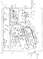
図1は、本発明の第1の実施例を採用した両面印刷装置を示している。同図において両面印刷装置1は、印刷部2、製版部3、給紙部4、排版部5、排紙部6、画像読取部7、補助トレイ8、再給紙手段9、切換部材10等を有している。
【0042】
印刷装置本体11のほぼ中央に配設された印刷部2は、版胴12とプレスローラー13とを有している。
版胴12は、インキ供給パイプを兼ねた支軸14に回転自在に支持された図示しない一対のフランジと、各フランジの外周面に巻装された図示しない多孔性支持板と、図示しない多孔性支持板の外周面に巻装された図示しないメッシュスクリーンとから主に構成されており、版胴駆動手段121(図8参照)によって回転駆動されると共に印刷装置本体11に対して着脱可能に構成されている。本実施例において版胴12は、片面印刷時において最大でA3サイズの印刷物を得ることが可能な大きさを有している。
【0043】
版胴12の内部にはインキ供給手段15が配設されている。インキ供給手段15は、支軸14、インキローラー16、ドクターローラー17等を有している。
インキローラー16は版胴12内に設けられた図示しない側板間に回転自在に支持されており、その周面を版胴12の内周面に近接して配置され、図示しない駆動手段によって版胴12と同方向に回転駆動される。ドクターローラー17も前記側板間に回転自在に支持されており、その周面をインキローラー16の周面に近接して配置され、図示しない駆動手段によって版胴12とは逆方向に回転駆動される。支軸14には複数の小さな孔が穿設されており、支軸14から供給されたインキがインキローラー16とドクターローラー17との近接部に形成される断面楔形状の空間に溜まることによりインキ溜まり18が形成される。
【0044】
版胴12の外周面上には、版胴12の一母線に沿った平面をなす図示しないステージ部が形成されており、この上には版胴12の外周面上にマスタの先端を保持させるクランパー19が配設されている。クランパー19は、版胴12が所定の位置まで回転されたときに図示しない開閉手段によって開閉される。
【0045】
版胴12の下方にはプレスローラー13が配設されている。プレスローラー13は金属製の芯部13aにゴム等の弾性体を巻成して構成されており、版胴12の軸方向に延在して設けられている。プレスローラー13は、図2に示すように芯部13aの両端部をプレスローラー支持部材としての一対のアーム部材20によって回転自在に支持されている。ほぼL字形状を呈する各アーム部材20は、その曲折部近傍の部位に取り付けられた揺動軸21によってそれぞれ一体化されており、揺動軸21は印刷装置本体11によって回動自在に支持されている。本実施例においてプレスローラー13は、少なくともその周面がポリテトラフルオロエチレン樹脂等の撥インキ性を有する部材によって構成されている。
【0046】
各アーム部材20間には、プレスローラー13の他、再給紙案内部材22、再給紙レジスト部材としての再給紙レジストローラー23、再給紙位置決め部材24、再給紙搬送部材25、クリーニング部材としてのクリーニングローラー26、ガイド板27等が設けられている。
【0047】
プレスローラー13の右方近傍に配設された再給紙案内部材22は、各支軸28a,29a,30a上にそれぞれ一体的に設けられそれぞれの周面をプレスローラー13の周面に圧接させた複数のころ状のローラー28,29,30と、用紙Pをプレスローラー13の周面に沿わせるための曲面状に形成された用紙ガイド板31とを有している。各支軸28a,29a,30aはそれぞれの両端部を各アーム部材20に回転自在に支持されており、図示しない付勢手段によってそれぞれ芯部13aに向けて付勢されている。各ローラー28,29,30は、対応する支軸28a,29a,30aに、プレスローラー13のほぼ全幅にわたってそれぞれ所定の間隔をもって一体的に取り付けられている。用紙ガイド板31はプレスローラー13の周面から各ローラー28,29,30の半径よりも小さな距離である所定距離だけ離れた位置に配設されており、その両端部を各アーム部材20に固着されている。用紙ガイド板31は芯部13aを中心とした曲面となるように形成されており、用紙ガイド板31には各ローラー28,29,30の周面をプレスローラー13の周面に当接させるための複数の開口部が形成されている。
【0048】
プレスローラー13の下方には再給紙レジストローラー23が配設されている。ころ状の再給紙レジストローラー23は支軸23aに回転自在に支持されており、支軸23aは再給紙レジスト支持部材としての揺動アーム32の一端に取り付けられている。ほぼへ字形状を呈する揺動アーム32は各アーム部材20間に固設された支軸32aにその曲折部を揺動自在に支持されており、その配設位置は再給紙レジストローラー23がプレスローラー13の幅方向のほぼ中央部に位置し、かつ自身が各ローラー30の配設位置の中間に位置するように定められている。揺動アーム32の他端には、図示しないブラケットを介して一方のアーム部材20に取り付けられたソレノイド33のプランジャ33aと、一端を一方のアーム部材20に固着され揺動アーム32に対して支軸32aを中心に図2において反時計回り方向への回動付勢力を付与する引張ばね34の他端とが取り付けられている。この構成より再給紙レジストローラー23は、ソレノイド33が作動されるとその周面を所定の圧接力でプレスローラー13の周面に圧接する図2に実線で示す圧接位置を占め、ソレノイド33の作動が解除されると引張ばね34の付勢力によってその周面がプレスローラー13の周面から離間する図2に二点鎖線で示す離間位置を占める。ソレノイド33と引張ばね34とによって再給紙レジスト接離機構40が構成されている。
【0049】
再給紙レジストローラー23の上方近傍には再給紙位置決め部材24が配設されている。再給紙位置決め部材24は断面L字形状を呈する板材からなり、その幅はプレスローラー13の幅とほぼ同じ幅となるように形成されていて、その曲折端部24aが上方を向く態様で両端部を各アーム部材20に固着されている。再給紙位置決め部材24には、再給紙レジストローラー23が揺動時に衝突しないための図示しない切欠部が形成されている。
【0050】
プレスローラー13の下方であって再給紙位置決め部材24の左方には再給紙搬送部材25が配設されている。再給紙搬送部材25は、搬送部材本体35、駆動ローラー36、従動ローラー37、無端ベルト38、吸引ファン39等を有しており、その上面に補助トレイ8を一体的に有している。
【0051】
上面が開放され、その幅が各アーム部材20間の間隔よりも若干小さくなるように形成された筐体である搬送部材本体35は用紙搬送方向上流側及び下流側の両側面に図示しない軸受を有しており、図示しない各軸受は駆動軸36a及び従動軸37aをそれぞれ回転自在に支持している。駆動軸36aはその両端部が搬送部材本体35の両側面を貫通しており、貫通した両端部は印刷装置本体11に設けられた図示しない軸受部材によって回転自在に支持されている。また、駆動軸36aの一端には図示しない駆動ギヤが取り付けられており、駆動軸36aは印刷装置本体11に設けられた搬送部材駆動モーター122(図8参照)によって回転駆動される。従動軸37aはその両端部が搬送部材本体35の両側面を貫通しないように構成されている。搬送部材本体35の用紙搬送方向上流側端部の両側面外側にはボス35aがそれぞれ一体的に設けられており、各ボス35aは各アーム部材20に形成された図示しない長穴にそれぞれ嵌合されている。この構成より搬送部材本体35は、後述するプレスローラー接離機構55によりプレスローラー13が版胴12に対して接離される際に、各アーム部材20の揺動に伴って駆動軸36aを中心とした揺動が可能となっている。
【0052】
ころ状をなす複数の駆動ローラー36はそれぞれ駆動軸36aに一体的に取り付けられており、各駆動ローラー36間にはそれぞれ所定の間隔が設けられている。駆動ローラー36と同形状である複数の従動ローラー37は、各駆動ローラー36と同間隔でそれぞれ従動軸37aに一体的に取り付けられている。各駆動ローラー36とこれに対応した各従動ローラー37との間には、図示しない複数の穴部を有する無端ベルト38が所定の張力で掛け渡されている。摩擦抵抗部材からなる無端ベルト38は、搬送部材駆動モーター122によって駆動軸36aが回転駆動されることにより図2に矢印で示す方向に移動される。
【0053】
搬送部材本体35の下面には吸引ファン39が一体的に取り付けられており、搬送部材本体35の上面には補助トレイ8が一体的に取り付けられている。補助トレイ8には各無端ベルト38を用紙搬送面に臨ませるための図示しない複数の開口部が形成されており、その用紙搬送方向下流側端部には搬送される用紙Pを受け止めるためのフェンス8aが一体的に形成されている。吸引ファン39の取付面である搬送部材本体35の下面には図示しない穴部が設けられており、これにより吸引ファン39が作動することで筐体である搬送部材本体35の内部に負圧を発生させ、移動する各無端ベルト38の上面に用紙Pを吸引させる。吸引ファン39の吸引力及び無端ベルト38の摩擦抵抗力は、用紙Pの先端が再給紙位置決め部材24の曲折端部24aに当接した際に、用紙Pと各無端ベルト38との間で滑りが発生する程度の強さにそれぞれ設定されている。
上述した再給紙案内部材22、再給紙レジストローラー23、再給紙位置決め部材24、及び再給紙搬送部材25によって再給紙手段9が構成されている。
【0054】
プレスローラー13の近傍であって再給紙搬送部材25の上方に位置する部位には、プレスローラー13の周面をクリーニングするクリーニングローラー26が配設されている。プレスローラー13の幅とほぼ同じ幅を有するクリーニングローラー26は、少なくともその表面が和紙やスポンジ等の吸湿性の高い材質によって構成されており、その中心に芯部26aを一体的に有している。クリーニングローラー26は芯部26aを各アーム部材20に形成された図示しない長穴に嵌合されることで回転自在に支持されており、この長穴内に設けられた図示しない付勢手段によってプレスローラー13に向けて付勢され、その周面をプレスローラー13の周面に所定の圧接力で常時圧接されている。クリーニングローラー26は、一方のアーム部材20に設けられた図示しないクリーニングローラー駆動手段によって、プレスローラー13の回転時においてプレスローラー13と同方向に、プレスローラー13の周速度の10分の1程度の周速度で回転駆動される。
【0055】
クリーニングローラー26の左上方にはガイド板27が配設されている。板材であるガイド板27はその両端部を各アーム部材20に固設されており、プレスローラー13によって版胴12に圧接された用紙Pがクリーニングローラー26に触れないように、かつ補助トレイ8に向かうように案内する。ガイド板27はプレスローラー13及びクリーニングローラー26の周面に近接する位置に配設されている。
【0056】
各アーム部材20のプレスローラー13が支持された一端側と対向する他端側には、それぞれ回転自在なカムフォロア41が互いに外側を向く態様で配設されている。また、各アーム部材20のカムフォロア41が配設された位置の近傍には、一端を印刷装置本体11に固着された印圧ばね42の他端がそれぞれ取り付けられている。これにより各アーム部材20は、揺動軸21を中心に図において時計回り方向への回動付勢力をそれぞれ付与されている。
【0057】
各カムフォロア41の左方近傍には、3枚のカム板43A,43B,43Cを有する多段カム43がそれぞれ配設されている。各カム板43A,43B,43Cは、両端を印刷装置本体11に回転自在かつ図2の紙面方向に移動自在に支持されたカム軸44にそれぞれ所定の間隙をもって固着されており、装置手前側からカム板43B、カム板43A、カム板43Cの順に配設されている。各カム板43A,43B,43Cは、カム軸44と同心の円板である基部とそれぞれ同一突出量の凸部とを有している。多段カム43は、図4に示すように、カム軸44に取り付けられた駆動ギヤ45及び印刷装置本体11に回転自在に支持された支軸46に取り付けられた伝達ギヤ47を介して版胴駆動手段121からの回転力を伝達され、図2において時計回り方向に回転駆動される。
【0058】
プレスローラー13は、各カム板43A,43B,43Cの何れかの凸部がカムフォロア41と当接したときにその周面が版胴12の周面より離間する図2に示す離間位置を占め、何れかの凸部とカムフォロア41との当接が解除されたときに印圧ばね42の付勢力によってその周面が版胴12の周面に圧接する図3に示す圧接位置を占める。各カム板43A,43B,43Cは、プレスローラー13が圧接位置を占めたときにその基部とカムフォロア41とが接触しないように構成されている。各カム板43A,43B,43Cの凸部の形状は、プレスローラー13と版胴12との接触範囲が、カム板43Aでは図1に示す表面領域と中間領域と裏面領域とを全て合わせた範囲となるように、カム板43Bでは表面領域と同じ範囲となるように、カム板43Cでは表面領域の下流側部分と中間領域と裏面領域とを合わせた範囲となるようにそれぞれ形成されている。また、各カム板43A,43B,43C間の間隔は、アーム部材20の板厚よりも十分に大きくなるように設定されている。
【0059】
図2において各アーム部材20の右方近傍には、プレスローラー13が離間位置を占めた状態で各アーム部材20の揺動を禁止する、図示しないプレスローラー係止手段が配設されている。図示しないプレスローラー係止手段は図示しないソレノイドを有しており、この図示しないソレノイドのオン・オフの切り換えによって各アーム部材20を保持する状態と保持を解除する状態とが選択的に切り換えられる。図示しないソレノイドは、カムフォロア41が各カム板43A,43B,43Cの何れかの凸部と当接した状態で作動される。
【0060】
カム軸44の下方近傍には、図4に示すように移動アーム48と段差カム49とが配設されている。ほぼL字形状を呈する移動アーム48は、印刷装置本体11に回転自在に支持された支軸48aにその曲折部を取り付けられており、移動アーム48の一端にはローラー48bが、また他端にはカムフォロア48cがそれぞれ回転自在に取り付けられている。さらに移動アーム48の他端と曲折部との間の部位には、一端を印刷装置本体11に取り付けられた引張ばね50の他端が取り付けられており、移動アーム48には支軸48aを中心に、図において時計回り方向への回動付勢力が付与されている。
【0061】
ローラー48bはカム軸44の中程に間隔をおいて固着された円板44a,44b間に配置されており、カムフォロア48cは引張ばね50の付勢力によりその周面を段差カム49の周面に当接させている。各円板44a,44b間の間隔は、ローラー48bの直径よりも僅かに大きくなるように設定されている。
【0062】
段差カム49はその周面に3箇所のカム部49a,49b,49cを有しており、印刷装置本体11に回転自在に支持された支軸51に固着されている。支軸51には、印刷装置本体11に取り付けられたステッピングモーター52の出力軸に取り付けられたギヤ53と噛合するギヤ54が取り付けられており、ステッピングモーター52の作動により段差カム49は図4の矢印方向に回転駆動される。この構成より、ステッピングモーター52が作動して段差カム49が回転すると移動アーム48が支軸48aを中心に揺動し、ローラー48bが円板44aあるいは円板44bを押すことでカム軸44が図4の左右方向に移動する。
【0063】
各カム部49a,49b,49cは、カムフォロア48cとカム部49aとが当接したときにカム板43Bがカムフォロア41と当接可能位置となるように、カムフォロア48cとカム部49bとが当接したときにカム板43Aがカムフォロア41と当接可能位置となるように、カムフォロア48cとカム部49cとが当接したときにカム板43Cがカムフォロア41と当接可能位置となるようにカム軸44を移動させる形状にそれぞれ形成されている。
【0064】
上述したカムフォロア41、印圧ばね42、多段カム43、図示しないプレスローラー係止手段、移動アーム48、段差カム49によってプレスローラー接離機構55が構成されており、このプレスローラー接離機構55の作動によってプレスローラー13は図2に示す離間位置と図3に示す圧接位置とを選択的に占める。
【0065】
版胴12とプレスローラー13との接触位置の左方であって用紙Pの搬送経路上には、用紙Pの搬送経路を切り換える切換部材10が配設されている。版胴12及びプレスローラー13とほぼ同じ幅を有する板材からなる切換部材10は、その用紙搬送方向下流側端部を印刷装置本体11に回動自在に支持された支軸に固着されており、ソレノイド123(図8参照)が作動することによって断面鋭角状に形成された用紙搬送方向上流側端部を図1に実線で示す第1の位置と二点鎖線で示す第2の位置とに選択的に位置決めされる。切換部材10は、第1の位置を占めたときにその先端がプレスローラー13の周面に近接すると共に版胴12上のクランパー19と干渉しない位置に置かれ、第2の位置を占めたときにその先端が版胴12の周面に近接する位置に置かれる。版胴12とプレスローラー13との間を通過した用紙Pは、切換部材10が第1の位置を占めたときに排紙部6へと案内され、切換部材10が第2の位置を占めたときにガイド板27と印刷装置本体11に固着されたガイド板56との間を通って補助トレイ8へと案内される。
【0066】
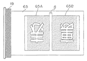
印刷装置本体11の右上部には製版部3が配設されている。製版部3は、マスタ保持部材57、プラテンローラー58、サーマルヘッド59、切断手段60、マスタストック部61、テンションローラー対62、反転ローラー対63等を有している。製版部3は後述するマスタ64に製版を行い、図5に示すような第1製版画像65Aと第2製版画像65Bとを有する分割製版済みマスタ65、あるいは図6に示すような第1製版画像65Aと第2製版画像65Bとの2面分の画像量域を有する第3製版画像66Aを有する製版済みマスタ66を作成する。第1製版画像65Aは、分割製版済みマスタ65が版胴12の外周面上に巻装されたときに図1に示す表面領域と対応する位置に形成され、第2製版画像65Bは裏面領域と対応する位置に形成される。
【0067】
マスタ保持部材57は印刷装置本体11の図示しない側板対にそれぞれ設けられており、熱可塑性樹脂フィルムと多孔性支持体とを貼り合わせたマスタ64をロール状に巻成してなるマスタロール64aの芯部64bの両端を回転自在かつ着脱自在に支持する。
【0068】
マスタ保持部材57の左方に設けられたプラテンローラー58は印刷装置本体11の図示しない側板に回転自在に支持されており、ステッピングモーターを含む製版駆動手段124(図8参照)によって回転駆動される。プラテンローラー58の下方に位置し多数の発熱素子を有するサーマルヘッド59は印刷装置本体11の図示しない側板に取り付けられており、図示しない付勢手段の付勢力によってその発熱素子面をプラテンローラー58に圧接されている。サーマルヘッド59はマスタ64の熱可塑性樹脂フィルム面に接触しつつ発熱素子を選択的に発熱させ、マスタ64に対して熱溶融穿孔製版を行う。
【0069】
プラテンローラー58及びサーマルヘッド59の左方には切断手段60が配設されている。印刷装置本体11の図示しないフレームに固設された固定刃60aと、この固定刃60aに移動自在に支持された可動刃60bとを有する切断手段60は、固定刃60aに対して可動刃60bが回転移動することによりマスタ64を切断する周知の構成である。
【0070】
切断手段60のマスタ搬送方向下流側下方にはマスタストック部61が配設されている。分割製版済みマスタ65あるいは製版済みマスタ66を一時的に貯容する空間であるマスタストック部61は複数の板部材によってその内部を仕切られており、その最奥部には図示しない吸引ファンが配設されている。この吸引ファンが作動することにより密閉された空間であるマスタストック部61の内部に負圧が発生し、製版して搬送されてきた分割製版済みマスタ65あるいは製版済みマスタ66はマスタストック部61の最奥部に向けて貯容される。
【0071】
切断手段60とマスタストック部61との間の部位にはテンションローラー対62が配設されている。それぞれ印刷装置本体11の図示しない側板に回転自在に支持された駆動ローラー62aと従動ローラー62bとからなるテンションローラー対62は、従動ローラー62bが図示しない付勢手段によってその周面を駆動ローラー62aの周面に圧接されており、製版駆動手段124によって駆動ローラー62aが回転駆動されることによりマスタ64を挟持して搬送する。駆動ローラー62aは、その周速度がプラテンローラー58の周速度よりも若干速く設定されていると共にその内部には図示しないトルクリミッターが設けられており、プラテンローラー58とテンションローラー対62との間においてマスタ64に対して所定の張力が付与されるように構成されている。
【0072】
マスタストック部61のマスタ搬送方向下流側には、それぞれ印刷装置本体11の図示しない側板に回転自在に支持された駆動ローラー63aと従動ローラー63bとからなる反転ローラー対63が配設されている。反転ローラー対63は、製版駆動手段124によって回転駆動される駆動ローラー63aと図示しない付勢手段によってこれに圧接配置された従動ローラー63bとによってマスタ64を挟持して搬送する。駆動ローラー63aの内部には図示しないワンウェイクラッチが設けられている。
【0073】
また、テンションローラー対62と反転ローラー対63との間の部位には、図示しない可動マスタガイド板が配設されている。この可動マスタガイド板は図示しない支持部材に揺動自在に支持されており、図示しないソレノイドによってその上面がマスタ64の搬送路を構成する搬送位置と、マスタ64のマスタストック部61への進入を妨げない退避位置とに選択的に位置決めされる。
【0074】
製版部3の下方には給紙部4が配設されている。給紙部4は、給紙トレイ67、給紙ローラー68、分離ローラー69、分離パッド70、レジストローラー対71等を有している。
上面に多数の用紙Pを積載可能な給紙トレイ67は印刷装置本体11に上下動自在に支持されており、昇降手段を含む給紙駆動手段125(図8参照)によって上下動される。A3サイズの用紙Pを縦置き可能な給紙トレイ67の上面には、図示しないレール部材によって用紙搬送方向と直行する用紙幅方向に移動自在に支持された一対のサイドフェンス72が設けられている。また、給紙トレイ67の自由端部側には、積載された用紙Pのサイズを検知する複数の用紙サイズ検知センサー73が設けられている。
【0075】
給紙トレイ67の上方には、表面に高摩擦抵抗部材を有する給紙ローラー68が配設されている。給紙ローラー68は印刷装置本体11に揺動自在に支持された図示しないブラケットに回転自在に支持されており、給紙トレイ67が図示しない昇降手段によって上昇されたときに所定の圧接力で給紙トレイ67上の最上位の用紙Pに圧接する。給紙ローラー68は給紙駆動手段125によって回転駆動される。
【0076】
給紙ローラー68の左方には、表面にそれぞれ高摩擦抵抗部材を有する分離ローラー69と分離パッド70とが配設されている。分離ローラー69はタイミングベルト69aを介して給紙ローラー68に駆動連結されており、給紙ローラー68の回転駆動時にこれと同期して同方向に回転駆動される。分離パッド70は図示しない付勢手段の付勢力によって分離ローラー69に圧接されている。
【0077】
分離ローラー69及び分離パッド70の左方にはレジストローラー対71が配設されている。駆動ローラー71aと従動ローラー71bとからなるレジストローラー対71は、版胴駆動手段121からの回転駆動力をギヤやカム等の図示しない駆動力伝達手段によって伝達されることで駆動ローラー71aが版胴12と同期した所定のタイミングで回転し、駆動ローラー71aに圧接された従動ローラー71bとによって用紙Pを印刷部2に向けて所定のタイミングで給送する。
【0078】
印刷部2の左上方には排版部5が配設されている。排版部5は、上排版部材74、下排版部材75、排版ボックス76、圧縮板77等を有している。
上排版部材74は、駆動ローラー78、従動ローラー79、無端ベルト80等を有し、排版駆動手段126(図8参照)によって駆動ローラー78が図の時計回り方向に回転駆動されることにより無端ベルト80が図1の矢印方向に移動する。下排版部材75は、駆動ローラー81、従動ローラー82、無端ベルト83等を有し、駆動ローラー78を回転駆動する排版駆動手段126の駆動力をギヤやベルト等の図示しない駆動力伝達手段によって伝達されることで駆動ローラー81が図の反時計回り方向に回転駆動されることにより、無端ベルト83が図1の矢印方向に移動する。また、下排版部材75は排版駆動手段126に含まれる図示しない移動手段によって移動自在に設けられており、図に示す位置と従動ローラー82の外周面上に位置する無端ベルト83が版胴12の外周面に当接する位置とを選択的に占める。
【0079】
内部に使用済みマスタを貯容する排版ボックス76は、印刷装置本体11に対して着脱自在に設けられている。上排版部材74と下排版部材75とによって運ばれた使用済みマスタを排版ボックス76の内部に押し込む圧縮板77は印刷装置本体11に上下動自在に支持されており、排版駆動手段126に含まれる図示しない昇降手段によって上下動される。
【0080】
排版部5の下方には排紙部6が配設されている。排紙部6は、剥離爪84、排紙搬送部材85、排紙トレイ86等を有している。
剥離爪84は版胴12の幅方向に複数配置され、印刷装置本体11に揺動自在に支持された支軸にそれぞれ一体的に取り付けられている。複数の剥離爪84は図示しない爪揺動手段によって揺動され、その先端が版胴12の周面に近接する図に示す位置と、クランパー19等の障害物を回避するためにその先端が版胴12の外周面から離間する位置とを選択的に占める。図示しない爪揺動手段は、版胴駆動手段121からの駆動力を図示しない駆動力伝達手段により伝達され、版胴12の回転と同期して剥離爪84を揺動させる。
【0081】
剥離爪84の下方であって切換部材10の左方に配設された排紙搬送部材85は、駆動ローラー87、従動ローラー88、無端ベルト89、吸引ファン90等を有している。ころ状の駆動ローラー87は図示しないユニット側板に回転自在に支持された図示しない支軸に所定の間隔で複数取り付けられており、排紙駆動手段127(図8参照)によってそれぞれ一体的に回転駆動される。従動ローラー88も同側板に回転自在に支持された図示しない支軸に各駆動ローラー87と等間隔で複数設けられており、各駆動ローラー87及びこれと対応する各従動ローラー88には複数の孔を有する無端ベルト89がそれぞれ掛け渡されている。駆動ローラー87、従動ローラー88、無端ベルト89の下方には吸引ファン90が配設されている。排紙搬送部材85は、吸引ファン90の吸引力によって各無端ベルト89上に用紙Pを吸引し、各駆動ローラー87の回転によって用紙Pを図1の矢印方向に搬送する。
排紙搬送部材85によって搬送された用紙Pをその上面に積載する排紙トレイ86は、用紙搬送方向に移動自在な1個のエンドフェンス91と、用紙幅方向に移動自在な一対のサイドフェンス92とを有している。
【0082】
印刷装置本体9の上部には画像読取部7が配設されている。画像読取部7は、原稿を載置するコンタクトガラス93、コンタクトガラス93に対して接離自在に設けられた圧板94、原稿画像を走査して読み取る反射ミラー95,96,97,98及び蛍光灯99、走査された原稿画像を集束するレンズ100、集束された画像を処理するCCD等の画像センサー101、原稿のサイズを検知する複数の原稿サイズ検知センサー102、読み取られた画像データを記憶する画像メモリ135等を有しており、原稿画像の読取動作は読取駆動手段128(図8参照)の作動によって行われる。
【0083】
また、図1に示すように、版胴12を構成する図示しないフランジの外面にはドグ133が取り付けられており、版胴12の周囲近傍には印刷装置本体11に取り付けられたホームポジションセンサー134が配設されている。ホームポジションセンサー134は、クランパー19がプレスローラー13と対向する位置を版胴12が占めたときにドグ133を検知して後述する制御手段129に向けて信号を出力する。
【0084】
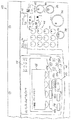
図7は両面印刷装置1の操作パネルを示している。同図において印刷装置本体11の上部前面に設けられた操作パネル103は、その上面に製版スタートキー104、印刷スタートキー105、試し刷りキー106、連続キー107、クリア/ストップキー108、テンキー109、エンターキー110、プログラムキー111、モードクリアキー112、印刷速度設定キー113、4方向キー114、用紙サイズ設定キー115、用紙厚み設定キー116、両面印刷キー117、片面印刷キー118、7セグメントLEDからなる表示装置119、LCDからなる表示装置120等を有している。
【0085】
製版スタートキー104は両面印刷装置1に製版動作を行わせる際に押下され、製版スタートキー104が押下されると排版動作及び原稿読取動作が行われた後に製版動作が行われ、その後、版付け動作が行われて両面印刷装置1は印刷待機状態となる。印刷スタートキー105は両面印刷装置1に印刷動作を行わせる際に押下され、両面印刷装置1が印刷待機状態となり各種印刷条件が設定された後に印刷スタートキー105が押下されることにより印刷動作が行われる。試し刷りキー106は両面印刷装置1に試し刷りを行わせる際に押下され、各種条件が設定された後に試し刷りキー106が押下されることにより1枚だけ印刷が行われる。連続キー107は製版動作と印刷動作とを連続して行う際に製版スタートキー104の押下前に押下され、連続キー107の押下後、印刷条件が入力された後に製版スタートキー104が押下されると、排版動作、原稿読取動作、製版動作に引き続いて印刷動作が行われる。
【0086】
クリア/ストップキー108は両面印刷装置1の動作を停止させる際あるいは置数のクリア時に押下され、テンキー109は数値入力に用いられる。エンターキー110は各種設定時に数値等を設定する際に、プログラムキー111はよく行う操作を登録したりそれを呼び出したりする際にそれぞれ押下され、モードクリアキー112は各種のモードをクリアして初期状態に戻す際に押下される。印刷速度設定キー113は印刷動作に先立って印刷速度を設定する際に押下され、濃いめの画像を得たい場合あるいは雰囲気温度が低い場合等には印刷速度を遅く、薄めの画像を得たい場合あるいは雰囲気温度が高い場合等には印刷速度を速く設定する。4方向キー114は上キー114a、下キー114b、左キー114c、右キー114dを有しており、画像編集時に画像位置を調整する場合あるいは各種設定時に数値や項目等を選択する場合等に押下される。
【0087】
用紙サイズ設定キー115は用紙サイズを任意で入力する際に押下され、用紙サイズ設定キー115で入力された用紙サイズは用紙サイズ検知センサー73によって検知された用紙サイズに優先される。用紙厚み設定キー116は両面印刷に先立って用紙Pの厚みを入力する際に押下され、本実施例では「普通紙」、「薄紙」、「厚紙」の3種類のうちの何れかを選択する構成となっている。
【0088】
両面印刷キー117は両面印刷装置1に両面印刷動作を行わせる際に製版スタートキー104の押下前に押下され、両面印刷キー117が押下されるとその近傍に配置されたLED117aが点灯してオペレーターに両面印刷モードであることが表示される。また、両面印刷キー117が押下された際には、用紙厚み設定キー116によって使用する用紙Pの厚みを入力した後でないと製版スタートキー104の入力が拒否される。片面印刷キー118も両面印刷キー117と同様に両面印刷装置1に片面印刷動作を行わせる際にスタートキー104の押下前に押下され、片面印刷キー118が押下されるとその近傍に配置されたLED118aが点灯してオペレーターに片面印刷モードであることが表示される。両面印刷装置1は初期状態時においてLED118aが点灯しており、片面印刷モードとなっている。
【0089】
7セグメントLEDからなる表示装置119は、主に印刷枚数等の数字を表示する。LCDからなる表示装置120は階層表示構造となっており、その下方に設けられた選択設定キー120a,120b,120c,120dを押下することにより、変倍や位置調整等の様々なモードへの変更及び各モードでの設定が可能に構成されている。また表示装置120には、図示したように「製版・プリントできます」のような両面印刷装置1の状態が表示される他、製版あるいは排版ジャム、給紙あるいは排紙ジャム等のアラーム、印刷用紙、マスタ、インキ等のサプライの供給指示等も表示される。
【0090】
図8は、両面印刷装置1に用いられる制御手段のブロック図を示している。同図において制御手段129は、内部にCPU130、ROM131、RAM132を有する周知のマイクロコンピューターであり、印刷装置本体11の内部に設けられている。
【0091】
CPU130は、操作パネル103からの各種信号及び印刷装置本体11に設けられた各種センサーからの検知信号及びROM131から呼び出された動作プログラムに基づいて、印刷部2、製版部3、給紙部4、排版部5、排紙部6、画像読取部7に設けられた各駆動手段、再給紙手段9に設けられた再給紙レジスト接離機構40及び搬送部材駆動モーター122、切換部材10を作動させるソレノイド123の作動等を制御し、両面印刷装置1全体の動作を制御する。ROM131には両面印刷装置1全体の動作プログラムが記憶されており、この動作プログラムはCPU130によって適宜呼び出される。RAM132は、CPU130の計算結果を一時的に記憶する機能、操作パネル103上の各種キー及び各種センサーから設定及び入力されたデータ信号及びオン・オフ信号を随時記憶する機能等を有している。また制御手段129は、ホームポジションセンサー134からのホームポジション信号と、版胴駆動手段121に設けられた図示しないエンコーダーからの信号とに基づいて、版胴12の位置の把握も行っている。
【0092】
上述の構成に基づき、以下に第1の実施例における両面印刷装置1の動作を説明する。
オペレーターは給紙トレイ67上に印刷に使用される用紙Pを積載し、圧板94を開放してコンタクトガラス93上に印刷すべき原稿を載置した後、再び圧板94を閉じる。その後、操作パネル103上の各種キーによって製版条件を設定した後、両面印刷キー117あるいは片面印刷キー118を押下して印刷モードを設定して製版スタートキー104を押下する。先ず、片面印刷キー118を押下して片面印刷を行う場合を説明する。
【0093】
オペレーターは片面印刷モードであることをLED118aの点灯によって確認した後、製版スタートキー104を押下する。製版スタートキー104が押下されると、用紙サイズ検知センサー73から用紙サイズ検知信号が、また原稿サイズ検知センサー102から原稿サイズ検知信号がそれぞれ制御手段129に送られ、信号を受けた制御手段129は各信号を比較する。このとき、用紙サイズと原稿サイズとが同じ場合は直ちに画像読取動作が行われ、用紙サイズと原稿サイズとが異なる場合には、制御手段129はその旨を表示装置120に表示してオペレーターに注意を促す。用紙サイズと原稿サイズとが異なる場合に、制御手段129からの指令で自動的に拡大または縮小の変倍を行い、原稿サイズと画像サイズとを整合させるように構成してもよい。
【0094】
製版スタートキー104が押下されると、画像読取部7では原稿画像の読取動作が行われる。原稿画像の読み取りは、蛍光灯99によって露光された反射光を各反射ミラー95,96,97,98によって反射することにより行われ、読み取られた原稿画像はレンズ100で集束された後に画像センサー101に入射されて光電変換される。光電変換された電気信号は印刷装置本体11内の図示しないA/D変換器に入力された後、画像メモリ135内に画像データ信号として格納される。
【0095】
画像読取部7での画像読取動作と並行して、排版部5では版胴12の外周面から使用済みマスタを剥離する排版動作が行われる。製版スタートキー104が押下されると版胴12が回転を開始し、版胴12が図1に示すホームポジションに達するとドグ133がホームポジションセンサー134に検知され、ホームポジションセンサー134から制御手段129に向けてホームポジション信号が送られる。ホームポジション信号を受けた制御手段129は、このホームポジションを基点として図示しないエンコーダーが発するパルス数を計測し、版胴12の外周面上に巻装された使用済みマスタの先端が従動ローラー82の外周面上に位置する無端ベルト83と対応する所定の排版位置に達したと判断すると、版胴駆動手段121の作動を停止させる。
【0096】
版胴駆動手段121が停止されて版胴12が所定の排版位置で停止すると、版胴駆動手段121及び排版駆動手段126が作動して各駆動ローラー78,81が回転駆動されると共に下排版部材75が版胴12側に移動し、従動ローラー82の外周面上に位置する無端ベルト83が使用済みマスタと当接する。すると、版胴12の回転及び無端ベルト83の移動によって版胴12の外周面上よりすくい上げられた使用済みマスタは、下排版部材75と上排版部材74とで挟持搬送されて版胴12の外周面より剥離される。剥離された使用済みマスタは排版ボックス76内に廃棄された後、圧縮板77によって圧縮される。
外周面上より使用済みマスタが全て剥離された後も版胴12は回転を継続し、クランパー19が右上方に位置する所定の給版待機位置まで回転して停止する。版胴12が給版待機位置で停止すると図示しない開閉手段が作動してクランパー19が開放され、両面印刷装置1は給版待機状態となる。
【0097】
排版動作と並行して、製版部3では製版動作が行われる。製版スタートキー104が押下されると、プラテンローラー58、テンションローラー対62、反転ローラー対63がそれぞれ回転駆動されてマスタロール64aよりマスタ64が引き出される。このとき図示しない可動マスタガイド板は搬送位置に位置決めされている。マスタ64が引き出されてその画像形成領域がサーマルヘッド59の発熱素子と対応する位置に達すると、画像メモリ135内に格納されている画像データ信号が画像処理を施された後に呼び出され、図示しないサーマルヘッドドライバーがサーマルヘッド59の各発熱素子を選択的に発熱させることにより、マスタ64の熱可塑性樹脂フィルム面に第3製版画像66Aが形成される。マスタ64は製版されつつ搬送されその先端部が反転ローラー対63に挟持されると、図示しない可動マスタガイド板が退避位置に移動されると共に反転ローラー対63の回転が停止される。
【0098】
反転ローラー対63の回転停止後もプラテンローラー58及びテンションローラー対62は回転を継続しており、サーマルヘッド59によって製版された製版済みマスタ66はマスタストック部61内に貯容される。反転ローラー対63の停止時においてマスタストック部61に設けられた図示しない吸引ファンが作動されており、製版済みマスタ66は図示しない吸引ファンに吸引されることによって良好にマスタストック部61内に貯容される。
【0099】
上述の製版動作中、排版動作が完了して両面印刷装置1が給版待機状態となると、反転ローラー対63が回転を開始してマスタストック部61内に貯容されている製版済みマスタ66が開放されているクランパー19に向けて搬送される。そして、製版済みマスタ66の先端部がクランパー19によって挟持可能な所定位置まで搬送されると、図示しない開閉手段が作動してクランパー19が閉じられ、製版済みマスタ66はその先端部を版胴12の外周面上に保持される。
【0100】
その後、版胴12が図1において時計回り方向に間欠的に回転駆動され、製版済みマスタ66の版胴12への巻装動作が行われる。このとき反転ローラー対63は回転を停止しており、駆動ローラー63aは内部に設けられた図示しないワンウェイクラッチによって製版済みマスタ66の引き出しに伴い連れ回りする。そして、画像メモリ135からの画像データ信号が途絶えるとサーマルヘッド59の作動が停止し、1版分の製版済みマスタ66が製版搬送されるとプラテンローラー58、テンションローラー対62、反転ローラー対63の回転がそれぞれ停止されると共に切断手段60が作動して製版済みマスタ66が切断される。切断された製版済みマスタ66は版胴12の回転によって製版部3より引き出され、版胴12がホームポジションまで回転して停止することで製版動作及び給版動作が完了する。
【0101】
給版動作に引き続き版付け動作が行われる。版胴12がホームポジションで停止するとソレノイド123が作動して切換部材10が第1の位置に位置決めされた後、図示しないプレスローラー係止手段が作動すると共にステッピングモーター52が作動して段差カム49が回転され、そのカム部49bをカムフォロア48cに当接させる。これにより移動アーム48が支軸48aを中心に揺動されてカム軸44がカム板43Aをカムフォロア41に対して当接可能となる位置に移動され、その後、図示しないプレスローラー係止手段の作動が解除される。
【0102】
その後、給紙ローラー68、分離ローラー69、駆動ローラー87、吸引ファン90がそれぞれ駆動されると共に版胴12が低速で図1の時計回り方向に回転駆動され、給紙トレイ67上に積載された用紙Pの最上位の1枚が引き出されてその先端をレジストローラー対71に挟持される。そして、版胴12上に巻装された製版済みマスタ66の版胴回転方向における第3製版画像66Aの画像領域先端部がプレスローラー13と対応する位置に到達する所定のタイミングで駆動ローラー71aが回転駆動され、引き出された用紙Pは版胴12とプレスローラー13との間に向けて給送される。
【0103】
版胴12の回転に同期して、プレスローラー接離機構55ではカム軸44及びこれと一体に設けられた多段カム43が回転駆動されており、上述したようにカムフォロア41と当接可能となる位置に移動されたカム板43Aは、上記所定のタイミングにおいてその凸部をカムフォロア41から離脱させる。これによりプレスローラー13がその周面を版胴12の外周面に印圧ばね42の付勢力によって圧接させ、レジストローラー対71によって給送された用紙Pが版胴12に巻装された製版済みマスタ66に押圧される。この押圧動作によりプレスローラー13と用紙Pと製版済みマスタ66と版胴12とが圧接し、インキローラー16によって版胴12の内周面に供給されたインキが版胴12の開口部より滲出し、版胴12を構成する図示しない多孔性支持板及び図示しないメッシュスクリーン、及び版胴12に巻装された製版済みマスタ66の多孔性支持体に充填された後に製版済みマスタ66の穿孔部を介して用紙Pに転写され、いわゆる版付けが行われる。
【0104】
版付けにより第3製版画像66Aに応じた画像を印刷された用紙Pは、第1の位置を占めた切換部材10によって排紙搬送部材85へと案内されると共に、剥離爪84によってその先端部から版胴外周面上の製版済みマスタ66より剥離される。剥離された用紙Pは下方へと落下して排紙搬送部材85へと送られ、吸引ファン90の吸引力によって無端ベルト89の上面に引きつけられつつ左方へと搬送されて排紙トレイ86上に排出される。その後、版胴12が再びホームポジションまで回転して停止し、版付け動作を終えて両面印刷装置1は印刷待機状態となる。
【0105】
両面印刷装置1が印刷待機状態となった後、印刷速度設定キー113及び操作パネル103上の各種キーによって印刷条件を入力した後に試し刷りキー106が押下されると試し刷りが行われる。試し刷りキー106が押下されると、設定された印刷速度で版胴12が回転駆動されると共に給紙部4から用紙Pが1枚給送される。給送された用紙Pはレジストローラー対71で一時停留された後に版付け時と同じタイミングで給送され、プレスローラー13によって版胴外周面上の製版済みマスタ66に圧接される。画像を印刷された用紙Pは切換部材10によって排紙部6へと案内された後、剥離爪84によって版胴外周面上の製版済みマスタ66より剥離され、排紙搬送部材85により搬送されて排紙トレイ86上に排出される。
【0106】
試し刷りにより画像の位置あるいは濃度等が確認され、テンキー109によって印刷枚数が入力された後に印刷スタートキー105が押下されると、給紙部4から用紙Pが連続的に給送され、試し刷りと同条件で印刷動作が行われる。そして、設定された印刷枚数が消化されると版胴12がホームポジションで停止し、両面印刷装置1は再び印刷待機状態となる。
【0107】
次に、両面印刷キー117を押下して両面印刷を行う場合を説明する。オペレーターは両面印刷モードであることをLED117aの点灯によって確認した後、用紙厚み設定キー116を押下して使用する用紙Pの厚みを設定する。この両面印刷モードでは、用紙厚み設定キー116が押下されない場合には製版スタートキー104の入力を拒否し、用紙厚み設定キー116が押下されずに製版スタートキー104が押下された場合には、制御手段129は用紙の厚みを設定して下さいという旨の表示を表示装置120に表示させる。本実施例において、用紙厚み設定キー116によって設定された用紙Pの厚みが「普通紙」あるいは「薄紙」の場合には製版スタートキー104の入力が許容され、「厚紙」が設定された場合には用紙Pの搬送ジャムを防止するために製版スタートキー104の入力が拒否されると共に、制御手段129は表示装置120に正しい用紙をセットして下さいという旨の警告を表示させる。このとき表示装置120は第1表示手段として機能する。
【0108】
給紙トレイ67上に「普通紙」あるいは「薄紙」である用紙Pがセットされ、用紙Pに基づいた用紙厚みが用紙厚み設定キー116によって設定された後に製版スタートキー104が押下されると、片面印刷時と同様に各センサー73,102から用紙サイズ検知信号及び原稿サイズ検知信号がそれぞれ制御手段129に送られ、制御手段129は入力された各信号を比較する。本実施例では、版胴12で印刷可能な最大用紙サイズがA3サイズであるため、両面印刷時において使用可能な用紙サイズはA4横置きまでである。原稿サイズと用紙サイズとを比較した結果、両サイズが同じ場合には直ちに画像読取動作が行われ、両サイズが異なる場合には、制御手段129はその旨を表示装置120に警告として表示してオペレーターに注意を促す。このとき表示装置120は第2表示手段として機能する。用紙サイズと原稿サイズとが異なる場合に、制御手段129からの指令で自動的に拡大または縮小の変倍を行って原稿サイズと画像サイズとを整合させる構成、表示装置120に縮小や画像データの回転等の手順を表示してオペレーターの操作の手助けを行う構成としてもよい。また、用紙サイズがA4横置きを超える大きさの場合には、制御手段129は両面印刷を禁止して片面印刷を促す旨を表示装置120に表示させる。
【0109】
製版スタートキー104が押下されると、画像読取部7では片面印刷時と同様に1枚目の原稿画像が読み取られる。読み取られた原稿画像は画像メモリ135内に1枚目の画像データ信号として格納される。1枚目の原稿の読取動作が完了して画像データ信号が画像メモリ135内に格納されると、制御手段129は表示装置120に2枚目の原稿をセットして下さいという旨の表示を行わせる。オペレーターはこの表示に従って圧板94を開放してコンタクトガラス93上より1枚目の原稿を取り除き、2枚目の原稿を載置して再び圧板94を閉じる。圧板94が閉じられたことを図示しないセンサーが検知し、コンタクトガラス93上に原稿があることを他の図示しないセンサーが検知すると、1枚目と同様に2枚目の原稿の読取動作が行われる。読み取られた原稿画像は画像メモリ135内に2枚目の画像データ信号として格納される。
【0110】
なお、本実施例において、片面印刷モード時及び両面印刷モード時における原稿の読取動作はオペレーターが圧板94を開閉してコンタクトガラス93上に読み取られる原稿をセットする構成としたが、ADFを用いて自動的に原稿をコンタクトガラス93上に搬送する構成、あるいは図示しない外部装置から画像データを取り込む構成としてもよい。また、両面印刷モード時において1枚の原稿を反転させて搬送し、その表面及び裏面から2枚分の画像データを取得する構成としてもよい。
【0111】
画像読取部7での画像読取動作と並行して、排版部5では片面印刷時と同様に排版動作が行われる。外周面上より使用済みマスタを剥離された版胴12は給版待機位置で停止し、図示しない開閉手段によってクランパー19が開放される。また、この排版動作と並行して製版部3では製版動作が行われる。製版動作は片面印刷モード時と同様の手順で行われるが、マスタ64にはその熱可塑性樹脂フィルム面に第1製版画像65Aと第2製版画像65Bとが形成される。このとき第1製版画像65Aと第2製版画像65Bとの間には、図5に示すように所定の空白部Sが設けられるように各画像65A,65Bが製版される。この所定の空白部Sは、分割製版済みマスタ65が版胴12の外周面上に巻装されたときに、図1に示す中間領域と対応する位置に設けられる。各画像65A,65Bが形成された分割製版済みマスタ65はマスタストック部61内に貯容され、排版動作が完了して両面印刷装置1が給版待機状態となると、反転ローラー対63の作動によって開放されているクランパー19に向けて搬送される。その後、版胴12が片面印刷モード時と同様に間欠回転され、分割製版済みマスタ65の版胴12への巻装が行われる。そして、画像メモリ135から2枚分の画像データが全て送られると、切断手段60が作動して分割製版済みマスタ65が切断される。切断された分割製版済みマスタ65は版胴12の回転によって製版部3より引き出され、版胴12がホームポジションで停止して製版動作及び給版動作が完了する。
【0112】
給版動作に引き続き版付け動作が行われる。版胴12がホームポジションで停止するとステッピングモーター52が作動して段差カム49が回転されると共に図示しないプレスローラー係止手段が作動され、カム部49aをカムフォロア48cに当接させる。これにより移動アーム48が支軸48aを中心に揺動されてカム軸44がカム板43Bをカムフォロア41に対して当接可能となる位置に移動された後、図示しないプレスローラー係止手段の作動が解除される。
【0113】
その後、給紙ローラー68、分離ローラー69、各駆動ローラー36,87、各吸引ファン39,90がそれぞれ駆動されると共に版胴12が低速で図1の時計回り方向に回転駆動され、給紙トレイ67上から1枚目の用紙P1が引き出されてその先端をレジストローラー対71に挟持される。そして、クランパー19が切換部材10と対応する位置を通過するとソレノイド123が作動して切換部材10が第2の位置に位置決めされ、その後、版胴12上に巻装された分割製版済みマスタ65の版胴回転方向における第1製版画像65Aの画像領域先端部がプレスローラー13と対応する位置に到達する所定のタイミングで駆動ローラー71aが回転駆動されることで、引き出された用紙P1は版胴12とプレスローラー13との間に向けて給送される。
【0114】
上記所定のタイミングにおいて、カムフォロア41と当接可能である位置に移動されたカム板43Bはその凸部をカムフォロア41から離脱させ、プレスローラー13が印圧ばね42の付勢力によってその周面を版胴12の外周面に圧接させる。これによりプレスローラー13と用紙P1と分割製版済みマスタ65の第1製版画像65A形成部と版胴12とが圧接し、インキローラー16によって版胴12の内周面に供給されたインキが版胴12の開口部より滲出し、版胴12に巻装された図示しない多孔性支持板及び図示しないメッシュスクリーン、及び分割製版済みマスタ65の多孔性支持体に充填された後に第1製版画像65Aの穿孔部を介して用紙P1に転写され、分割製版済みマスタ65のうちの第1製版画像65Aが形成された部分の版付けが行われる。
【0115】
版付けにより第1製版画像65Aに応じた画像をその表面に印刷された用紙P1は、切換部材10の先端によってその先端部から版胴外周面上の分割製版済みマスタ65から剥離されつつ、第2の位置を占めた切換部材10によって再給紙手段9へと案内される。切換部材10によって下方へと導かれた用紙P1は、各ガイド板27,56間を通ってその先端をフェンス8aに当接させ、補助トレイ8上に載置される。補助トレイ8上に搬送された用紙P1は吸引ファン39の吸引力によって無端ベルト38に保持されつつ図1の矢印方向に搬送され、その先端(第1製版画像65Aの印刷時における後端)を曲折端部24aに当接させる。このとき用紙P1と無端ベルト38との間で滑りが発生するので、用紙P1はその先端を曲折端部24aに当接させた状態で停留される。なお、用紙P1の先端が曲折端部24aに当接したときにこれを検知する図示しないセンサーを設け、この図示しないセンサーが用紙P1の先端を検知したときに駆動ローラー36及び吸引ファン39の作動を停止させる構成としてもよい。
【0116】
用紙P1が補助トレイ8上に案内されている間も版胴12は回転を継続しており、プレスローラー13は版胴12の表面領域との接触を終えるとカム板43Bの凸部がカムフォロア41に当接することで離間位置を占める。このカム板43Bの働きにより、用紙Pが存在しない状態で版胴12の裏面領域とプレスローラー13とが圧接することがなく、プレスローラー13の周面へのインキの転移を防止できる。このとき図示しないプレスローラー係止手段が作動してプレスローラー13を離間位置で保持した後、ステッピングモーター52が作動して段差カム49が回転され、そのカム部49bをカムフォロア48cに当接させる。これにより移動アーム48が支軸48aを中心に揺動され、カム軸44がカム板43Aをカムフォロア41に対して当接可能となる位置に移動される。
【0117】
また、上述の動作とほぼ同時に給紙ローラー68及び分離ローラー69が駆動され、給紙トレイ67上から2枚目の用紙P2が引き出されてその先端をレジストローラー対71に挟持される。そして、上述と同様の所定のタイミングで駆動ローラー71aが回転駆動され、引き出された用紙P2は版胴12とプレスローラー13との間に向けて給送される。
【0118】
一方、プレスローラー接離機構55では、移動されたカム板43Aの凸部がカムフォロア41と当接可能な位置までカム軸44が回転すると、図示しないプレスローラー係止手段の作動が解除される。このときカム軸44と同期して回転している版胴12は、表面領域及び裏面領域及び中間領域以外の部位である非開口部がプレスローラー13と対向する位置を占めている。また、版胴12の表面領域がプレスローラー13との対向部を通過し、クランパー19が再び切換部材10と対応する位置を占めるまでの間にソレノイド123が作動され、切換部材10が第2の位置から第1の位置に変位される。
【0119】
用紙P2がレジストローラー対71によって給送される所定のタイミングにおいて、カム板43Aがその凸部をカムフォロア41から離脱させることによりプレスローラー13が印圧ばね42の付勢力によってその周面を版胴12の外周面に圧接させる。これによりプレスローラー13と用紙P2と分割製版済みマスタ65の第1製版画像65A形成部と版胴12とが圧接し、インキローラー16によって版胴12の内周面に供給されたインキが版胴12の開口部、図示しない多孔性支持板及び図示しないメッシュスクリーン、第1製版画像65Aの穿孔部を介して用紙P2に転写される。
【0120】
第1製版画像65Aに応じた画像を印刷された用紙P2は、第1の位置を占めた切換部材10によって排紙搬送部材85へと案内されると共に、剥離爪84によってその先端部から版胴外周面上の分割製版済みマスタ65より剥離される。剥離された用紙P2は下方へと落下して排紙搬送部材85へと送られた後に排紙トレイ86上に排出される。
【0121】
また、レジストローラー対71によって用紙P2が給送された後、分割製版済みマスタ65の版胴回転方向における第2製版画像65Bの画像領域先端部がプレスローラー13と対応する位置に到達するよりもやや早いタイミングである所定のタイミングでソレノイド33が作動され、揺動アーム32が支軸32aを中心に図2における時計回り方向に揺動される。これにより再給紙レジストローラー23が離間位置から圧接位置に揺動され、先端を曲折端部24aに当接させた状態で停留されていた用紙P1が版胴12と当接して従動回転しているプレスローラー13の周面に当接される。
【0122】
再給紙レジストローラー23によりプレスローラー13の周面に当接された用紙P1は、プレスローラー13の回転力によってその回転方向下流側へと搬送され、用紙ガイド板31及び各ローラー28,29,30によってプレスローラー13の周面に密着した状態で版胴12との当接部に向けて搬送される。このとき用紙P1の表面には第1製版画像65Aに応じた画像が印刷されているが、再給紙案内部材22の働きによって用紙P1がプレスローラー13の周面に密着されているので、一度プレスローラー13の周面に接触した用紙P1がずれることがなく、擦れ汚れあるいは画線の太りといった不具合の発生が防止される。そして、用紙P2の後端及び中間領域がプレスローラー13と対応する位置を通過した後、裏面領域の先端部がプレスローラー13と対応する位置に到達するタイミングで用紙P1が版胴12とプレスローラー13との当接部に送り込まれる。
【0123】
これによりプレスローラー13と用紙P1と分割製版済みマスタ65の第2製版画像65B形成部と版胴12とが圧接し、インキローラー16によって版胴12の内周面に供給されたインキが版胴12の開口部、図示しない多孔性支持板及び図示しないメッシュスクリーン、第2製版画像65Bの穿孔部を介して用紙P1に転写され、分割製版済みマスタ65のうちの第2製版画像65Bが形成された部分の版付けが行われる。
【0124】
第1製版画像65Aに応じた画像を表面に、第2製版画像65Bに応じた画像を裏面にそれぞれ印刷された用紙P1は、第1の位置を占めた切換部材10によって排紙搬送部材85へと案内されると共に、剥離爪84によってその先端部から版胴外周面上の分割製版済みマスタ65より剥離される。剥離された用紙P1は下方へと落下して排紙搬送部材85へと送られた後に排紙トレイ86上に排出され、これにより分割製版済みマスタ65の版付け動作が完了して両面印刷装置1は印刷待機状態となる。
【0125】
上述の版付け時において、分割製版済みマスタ65の第1製版画像65Aと第2製版画像65Bとの間に所定の空白部Sが設けられ、分割製版済みマスタ65が版胴12の外周面上に巻装された際に中間領域が形成されるので、給紙部4から送られた用紙P2の後端と再給紙手段9から送られた用紙P1の先端とが重合することが防止され、良好な版付けを行うことができる。また、再給紙手段9からの用紙P1の再給紙時において、用紙P1の印刷面と接触することでプレスローラー13の表面に用紙P1からのインキが再転移するが、プレスローラー13の周面が撥インキ性を有すると共にクリーニングローラー26がプレスローラー13の周面をクリーニングするので、用紙P1からプレスローラー13の周面への再転移インキ量が減少されると共にプレスローラー13の周面からの再転移インキの除去が促進され、以下の印刷時においてプレスローラー13から用紙Pの裏面へのインキの再転移を防止できる。
【0126】
両面印刷装置1が印刷待機状態となった後、印刷速度設定キー113及び操作パネル103上の各種キーによって印刷条件を入力した後に試し刷りキー106が押下されると、試し刷りが行われる。この試し刷りキー106の押下時においても制御手段129は用紙の厚みを設定して下さいという旨の表示を表示装置120に表示させ、「厚紙」が設定された場合には試し刷りキー106の入力を拒否して表示装置120に正しい用紙をセットして下さいという旨の警告を表示させる。
【0127】
試し刷りキー106が押下されると、版付け時と同様にカム板43Bがカムフォロア41に当接可能となる位置にカム軸44が移動された後に設定された印刷速度で版胴12が回転駆動され、さらに版付け時と同様に切換部材10が第2の位置に位置決めされる。版胴12の回転開始後、給紙部4から1枚目の用紙P1が給送され、給送された用紙P1はレジストローラー対71で一時停留された後に版付け時と同じタイミングで給送されてプレスローラー13によって分割製版済みマスタ65の第1製版画像65Aに圧接される。表面に第1製版画像65Aに対応した画像を印刷された用紙P1は切換部材10によって版胴外周面上の分割製版済みマスタ65より剥離されつつ補助トレイ8へと案内される。補助トレイ8上に搬送された用紙P1は、吸引ファン39の吸引力によって無端ベルト38上に保持されつつ先端を曲折端部24aに当接させた状態で停留される。
【0128】
その後、図示しないプレスローラー係止手段が作動してプレスローラー13が離間位置で保持され、段差カム49が回転してカム板43Aをカムフォロア41に対して当接可能となる位置にカム軸44が移動された後、図示しないプレスローラー係止手段の作動が解除される。切換部材10は、クランパー19が再び切換部材10と対応する位置を占めるまでの間に第2の位置から第1の位置に変位される。また、この動作とほぼ同時に給紙部4から2枚目の用紙P2が給送され、給送された用紙P2はレジストローラー対71で一時停留された後に用紙P1と同じタイミングで印刷部2に向けて給送される。
【0129】
給送された用紙P2は揺動するプレスローラー13によって分割製版済みマスタ65の第1製版画像65Aに圧接され、表面に第1製版画像65Aに対応した画像を印刷された用紙P2は第1の位置を占めた切換部材10によって排紙搬送部材85へと案内される。用紙P2は剥離爪84によって分割製版済みマスタ65より剥離され、下方へと落下して排紙搬送部材85によって搬送されて排紙トレイ86上に排出される。
【0130】
レジストローラー対71によって用紙P2が給送された後、版付け時と同じタイミングでソレノイド33が作動されて再給紙レジストローラー23が離間位置から圧接位置へと変位され、一時停留されていた用紙P1が回転しているプレスローラー13の周面に当接される。用紙P1はプレスローラー13の回転力によって搬送され、再給紙案内部材22によってプレスローラー13の周面に密着した状態で印刷部2へと搬送される。
【0131】
搬送された用紙P1は揺動するプレスローラー13によって分割製版済みマスタ65の第2製版画像65Bに圧接され、その両面に各製版画像65A,65Bに対応した画像を印刷された用紙P1は切換部材10によって排紙搬送部材85へと案内される。その後、用紙P1が剥離爪84によって分割製版済みマスタ65より剥離され、排紙搬送部材85によって搬送されて排紙トレイ86上に排出されることにより試し刷りが完了する。
【0132】
試し刷りにより画像の位置あるいは濃度等が確認され、テンキー109によって印刷枚数が入力された後に印刷スタートキー105が押下されると、印刷動作が行われる。この印刷スタートキー105の押下時においても制御手段129は用紙の厚みを設定して下さいという旨の表示を表示装置120に表示させ、「厚紙」が設定された場合には印刷スタートキー105の入力を拒否して表示装置120に正しい用紙をセットして下さいという旨の警告を表示させる。本実施例では、印刷枚数としてN枚が入力された場合を説明する。
【0133】
印刷スタートキー105が押下されると、版付け時及び試し刷り時と同様にカム板43Bがカムフォロア41に対して当接可能となる位置にカム軸44が移動された後に設定された印刷速度で版胴12が回転駆動され、さらに版付け時及び試し刷り時と同様に切換部材10が第2の位置に位置決めされる。版胴12の回転開始後に給紙部4から1枚目の用紙P1が給送され、給送された用紙P1はレジストローラー対71で一時停留された後に試し刷り時と同じタイミングで給送される。用紙P1はプレスローラー13によって分割製版済みマスタ65の第1製版画像65Aに圧接されることで、その表面に第1製版画像65Aに対応した画像を印刷される。表面に画像を印刷された用紙P1は、第2の位置を占めた切換部材10によって剥離案内されて補助トレイ8上に搬送され、先端を曲折端部24aに当接させた状態で停留される。
【0134】
その後、図示しないプレスローラー係止手段が作動してプレスローラー13が離間位置で保持され、カム板43Aがカムフォロア41に対して当接可能となる位置にカム軸44が移動された後、図示しないプレスローラー係止手段の作動が解除される。また、この動作とほぼ同時に給紙部4から2枚目の用紙P2が給送され、用紙P2はレジストローラー対71で一時停留された後に用紙P1と同じタイミングで印刷部2に向けて給送される。切換部材10はクランパー19との衝突を回避すべく第1の位置に位置決めされた後、クランパー19の通過後に再び第2の位置に位置決めされる。
【0135】
給送された用紙P2はプレスローラー13によって分割製版済みマスタ65の第1製版画像65Aに圧接され、表面に第1製版画像65Aに対応した画像を印刷された後、第2の位置を占めた切換部材10によって剥離案内されて補助トレイ8上に搬送される。このとき試し刷り時と同じタイミングでソレノイド33が作動され、補助トレイ8上に停留されていた用紙P1がプレスローラー13の回転力によって印刷部2へと搬送される。用紙P1は用紙P2の後端が版胴12とプレスローラー13との当接部を抜けきった後、版胴12の中間領域がプレスローラー13と対向する位置を通過して裏面領域がプレスローラー13と対向するタイミングで版胴12とプレスローラー13との当接部に送られ、プレスローラー13によって分割製版済みマスタ65の第2製版画像65Bに圧接されることでその裏面に第2製版画像65Bに対応した画像を印刷される。
【0136】
上述の動作中、版胴12の中間領域がプレスローラー13と対向する位置を占める直前にソレノイド123が作動され、切換部材10が第2の位置から第1の位置に変位される。これにより切換部材10によって案内されていた用紙P2の後端は、切換部材10の下面10aとプレスローラー13の周面との間の僅かな隙間を通って補助トレイ8上に案内され、これに続いて搬送された用紙P1の先端は、切換部材10の上面10bに沿って排紙搬送部材85へと案内される。用紙P1は、剥離爪84によって分割製版済みマスタ65より剥離された後に排紙搬送部材85によって搬送され、排紙トレイ86上に排出される。
【0137】
その後、給紙部4から3枚目の用紙P3が給送され、用紙P3はレジストローラー対71で一時停留された後に用紙P1と同じタイミングで印刷部2に向けて給送される。切換部材10はクランパー19との衝突を回避すべく第1の位置に位置決めされ、クランパー19の通過後に再び第2の位置に位置決めされる。給送された用紙P3は表面に第1製版画像65Aに対応した画像を印刷された後、切換部材10によって補助トレイ8上に案内される。そして所定のタイミングでソレノイド33が作動され、補助トレイ8上に停留されていた用紙P2が印刷部2へと搬送される。用紙P2は上述の用紙P1と同様のタイミングで版胴12とプレスローラー13との当接部に送られ、その裏面に第2製版画像65Bに対応した画像を印刷される。切換部材10は上述と同様のタイミングで第2の位置から第1の位置に変位され、用紙P3の後端は切換部材10の下面10aとプレスローラー13の周面との間の僅かな隙間を通って補助トレイ8上に案内される。また、これに続いて補助トレイ8上より搬送された用紙P2の先端は切換部材10の上面10bに沿って排紙搬送部材85へと案内され、用紙P2は剥離爪84によって分割製版済みマスタ65より剥離された後に排紙搬送部材85によって搬送され、排紙トレイ86上に排出される。
【0138】
以下、上述と同様の印刷動作が(N―1)枚目まで行われる。そして、N枚目の用紙PNが給紙部4から給送されその表面に第1製版画像65Aに対応した画像を印刷されて補助トレイ8上に案内された後、(N−1)枚目の用紙P(N−1)がその裏面に第2製版画像に対応した画像を印刷されて排紙トレイ86上に排出されると、図示しないプレスローラー係止手段が作動してプレスローラー13が離間位置で保持され、カム板43Cをカムフォロア41に対して当接可能となる位置にカム軸44が移動された後、図示しないプレスローラー係止手段の作動が解除される。このとき切換部材10は第1の位置を占めた状態を維持している。
【0139】
そして、分割製版済みマスタ65の版胴回転方向における第2製版画像65Bの画像領域先端部がプレスローラー13と対応する位置に到達するよりも早い第1のタイミングでカムフォロア41と当接可能である位置に移動されたカム板43Cはその凸部をカムフォロア41から離脱させ、プレスローラー13が印圧ばね42の付勢力によってその周面を版胴12の外周面に圧接させる。その後、分割製版済みマスタ65の版胴回転方向における第2製版画像65Bの画像領域先端部がプレスローラー13と対応する位置に到達するよりもやや早い第2のタイミングでソレノイド33が作動され、揺動アーム32が支軸32aを中心に図2における時計回り方向に揺動される。これにより再給紙レジストローラー23が離間位置から圧接位置に揺動され、先端を曲折端部24aに当接させた状態で停留されていた用紙PNが版胴12と当接して従動回転しているプレスローラー13の周面に当接される。
【0140】
用紙PNは用紙P1と同様のタイミングで版胴12とプレスローラー13との当接部に送られ、その裏面に第2製版画像65Bに対応した画像を印刷される。画像を印刷された用紙PNは切換部材10の上面10bに沿って排紙搬送部材85へと案内され、剥離爪84によって分割製版済みマスタ65より剥離された後に排紙搬送部材85によって搬送され、排紙トレイ86上に排出される。その後、プレスローラー13は版胴12の裏面領域との接触を終えるとカム板43Cの凸部がカムフォロア41に当接することで離間位置を占める。このカム板43Cの働きにより、用紙Pが存在しない状態で版胴12の表面領域とプレスローラー13とが圧接することがなく、プレスローラー13の周面へのインキの転移を防止できる。このとき図示しないプレスローラー係止手段が作動してプレスローラー13が離間位置で保持され、その後に版胴12がホームポジションで停止して両面印刷装置1は印刷動作を終えて再び印刷待機状態となる。
【0141】
上述の印刷時において、分割製版済みマスタ65の第1製版画像65Aと第2製版画像65Bとの間に所定の空白部Sが設けられ、分割製版済みマスタ65が版胴12の外周面上に巻装された際に中間領域が形成されるので、給紙部4から送られた用紙Pの後端と再給紙手段9から送られた用紙Pの先端とが重合することが防止され、切換部材10の切換によって給紙部4からの用紙Pを補助トレイ8に、再給紙手段9からの用紙Pを排紙トレイ86にそれぞれ確実に搬送することができる。また、再給紙手段9からの用紙Pの再給紙時において、用紙Pの印刷面及び版胴12の外周面と接触することでプレスローラー13の表面に用紙Pからのインキ及び版胴外周面からのインキが再転移するが、プレスローラー13の周面が撥インキ性を有すると共にクリーニングローラー26がプレスローラー13の周面をクリーニングするので、用紙Pからプレスローラー13の周面への再転移インキが減少されると共にプレスローラー13の周面からの再転移インキの除去が促進され、以下の印刷時においてプレスローラー13から用紙Pの裏面へのインキの再転移を防止できる。
【0142】
この両面印刷装置1によれば、片面印刷時には製版部3が製版済みマスタ66を作成してこれを版胴12に巻装し、給紙部4より用紙Pを給送してこれをプレスローラー13によって版胴12に圧接させるので、マスタ64を無駄に使用することなく通常の孔版印刷装置と同様に片面印刷を行うことができる。また、両面印刷時には製版部3が分割製版済みマスタ65を作成してこれを版胴12に巻装し、給紙部4より1枚目の用紙P1を給送してこの表面をプレスローラー13によって版胴12に圧接させた後に補助トレイ8上に排出し、給紙部4より2枚目の用紙P2を給送してこの表面をプレスローラー13によって版胴12に圧接させた後に補助トレイ8上に排出すると共に、再給紙手段9によって1枚目の用紙P1を反転給送してこの裏面をプレスローラー13によって版胴12に圧接させた後に排紙トレイ86上に排出するので、用紙Pに印刷される表面画像及び裏面画像が共にプレスローラー13により版胴12から転移されるインキによって形成され、良好な両面印刷物を得ることができる。
【0143】
また、印刷部2の構成が版胴12と版胴12よりも小径のプレスローラー13とからなり、補助トレイ8が排紙部6を構成する排紙搬送部材85の下方に配設されているので、通常の片面印刷用の孔版印刷装置に比して大幅に大型化することなく装置を構成でき、設置スペースの増大を抑制することができる。
【0144】
上記実施例では、両面印刷時において2枚の原稿を用意し、マスタ64上に各原稿に応じた第1製版画像65Aと第2製版画像65Bとを製版して分割製版済みマスタ65を作成して1種類の両面印刷物を得る構成を示したが、画像読取部7にADFを設けて複数枚(3枚以上)の原稿をセットし、両面印刷装置1にソーターを接続して複数種類の両面印刷物を順次得ることももちろん可能である。この場合、原稿の枚数が奇数の場合には最後の1枚の原稿が製版されずに余ってしまうが、これを片面印刷モードで処理すると印刷面が上向きでソーターに排出されてしまうため、最終ページとその直前のページとの間に空白のページが挿入されてしまう。そこで、原稿が奇数枚の場合でも全てを両面印刷モードで処理し、最後の1枚の原稿を第1製版画像65Aとすると共に第2製版画像65Bを空白(未製版)として分割製版済みマスタ65を作成して上述と同様の印刷動作を行うことにより、原稿を余らせることなくかつページ順を狂わせることなく複数種類の両面印刷物を得ることができる。
【0145】
上記実施例では、両面印刷時に画像読取部7で2枚の原稿を順次読み取り、読み取られた原稿をその読み取られた順に製版部3において製版し、1枚目の原稿に応じた第1製版画像65Aと2枚目の原稿に応じた第2製版画像65Bとが製版された分割製版済みマスタ65を作成する構成としたが、画像メモリ135に格納されている2枚分の原稿画像に応じた各画像データ信号の製版量(サーマルヘッド59の各発熱素子の稼働率、すなわちべた部の有無及びその数量)を比較する比較手段を設け、製版量の少ない画像を第1製版画像65Aとして、製版量の多い画像を第2製版画像65Bとして製版させる構成を採用してもよい。この構成とすることにより、版胴12から用紙Pの表面に転移されるインキ量が裏面に転移されるインキ量よりも少なくなり、再給紙手段9によって補助トレイ8上から表面印刷済みの用紙Pが給送される際に、用紙Pからプレスローラー13の周面に再転移されるインキ量を減少させることができ、良好な両面印刷物を得ることができると共にクリーニング部材の負担を軽減させてその寿命を延ばすことができる。
【0146】
上記実施例では、プレスローラー13の周面をクリーニングするクリーニング部材として、図示しない付勢手段によってプレスローラー13の周面に常時圧接されたクリーニングローラー26を用いたが、クリーニング部材として再給紙レジストローラー23と同様に、図示しない接離手段によってプレスローラー13の周面に対して接離自在に構成されたものを用いてもよい。この場合、プレスローラー13の周面に用紙Pからのインキが再転移しない片面印刷時にはクリーニング部材をプレスローラー13の周面から離間させることで、クリーニング部材の劣化を抑制することができる。
【0147】
上記実施例では、両面印刷モードの版付け時及び試し刷り時において、カム板43Bがカムフォロア41と当接可能となるようにカム軸44を移動させた後に給紙部4から1枚目の用紙P1を給送し、用紙P1の表面に第1製版画像65Aを印刷してこれを補助トレイ8に案内した後、カム板43Aがカムフォロア41と当接可能となるようにカム軸44を移動させて給紙部4から2枚目の用紙P2を給送し、用紙P2の表面に第1製版画像65Aを印刷してこれを排紙トレイ86に排出すると共に補助トレイ8から用紙P1を給送してその裏面に第2製版画像65Bを印刷してこれを排紙トレイ86に排出する構成としたが、カム板43Bがカムフォロア41と当接可能となるようにカム軸44を移動させた後に給紙部4から1枚の用紙Pを給送し、用紙Pの表面に第1製版画像65Aを印刷してこれを補助トレイ8に案内した後にカム板43Cがカムフォロア41と当接可能となるようにカム軸44を移動させ、プレスローラー13の周面を版胴12の外周面に圧接させた後に分割製版済みマスタ65の版胴回転方向における第2製版画像65Bの画像領域先端部がプレスローラー13と対応する位置に到達するよりもやや早いタイミングでソレノイド33を作動させ、補助トレイ8から用紙Pを給送してその裏面に第2製版画像65Bを印刷してこれを排紙トレイ86に排出する構成としてもよい。この構成とすることにより版付け及び試し刷りを1枚の用紙Pで賄うことができ、コストを低減することができる。
【0148】
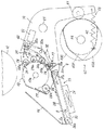
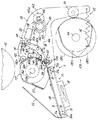
図9は、本発明の第2の実施例を示している。この第2の実施例は第1の実施例と比較すると、プレスローラー13に代えてプレスローラー136を用いる点、クリーニングローラー26に代えてクリーニング部材としてのクリーニングローラー137を用いる点、多段カム43に代えて多段カム138を用いる点、プレスローラー回転駆動手段139を用いる点においてのみ相違しており、他の構成は同一である。
【0149】
プレスローラー13と同形状を呈し、少なくともその周面が撥インキ性を有する部材で構成されたプレスローラー136は、その芯部136aの両端部を各アーム部材20によって回転自在に支持されている。芯部136aは装置奥側の一端がアーム部材20より突出していて、その突出した端部には装置手前側から順にタイミングプーリー140とクリーニングローラー駆動ギヤ141とが固着されている。
【0150】
一方、揺動軸21の装置奥側に位置するアーム部材20よりもさらに装置奥側に突出した部位には、装置手前側から順にタイミングプーリー142とプレスローラー駆動ギヤ143とがそれぞれ図示しない軸受を介して回転自在に取り付けられている。タイミングプーリー142はタイミングプーリー140と同じ形状を呈しており、各タイミングプーリー140,142間にはタイミングベルト144が掛け渡されている。プレスローラー駆動ギヤ143の近傍には印刷装置本体11に取り付けられたプレスローラー駆動モーター145が配設されており、その出力軸145aにはプレスローラー駆動ギヤ143に噛合するピニオン146が取り付けられている。プレスローラー駆動モーター145の作動は制御手段129によって制御される。
【0151】
上述した各タイミングプーリー140,142、プレスローラー駆動ギヤ143、タイミングベルト144、プレスローラー駆動モーター145、ピニオン146によってプレスローラー回転駆動手段139が構成されている。プレスローラー回転駆動手段139は、版胴12の回転周速度と同じ回転周速度でプレスローラー136を回転駆動するように構成されており、各タイミングプーリー140,142、タイミングベルト144によって駆動力伝達手段150が構成されている。
【0152】
クリーニングローラー26と同様に構成されたクリーニングローラー137は、その芯部137aをクリーニングローラー26における芯部26aと同じ位置でありかつ同じ態様で各アーム部材20によって回転自在に支持されている。芯部137aの装置奥側端部はアーム部材20より突出しており、その突出した端部には従動ギヤ147が取り付けられている。装置奥側に配置されたアーム部材20の装置奥側側面上であって、各芯部136a,137aが支持された位置の中間には、支軸148が植設されている。支軸148には、クリーニングローラー駆動ギヤ141に噛合する大径ギヤ149aと従動ギヤ147に噛合する小径ギヤ149bとを一体的に有する減速アイドルギヤ149が図示しない軸受を介して回転自在に取り付けられている。クリーニングローラー駆動ギヤ141、従動ギヤ147、大径ギヤ149a、小径ギヤ149bは、クリーニングローラー137の回転周速度がプレスローラー136の回転周速度の10分の1程度となるように、それぞれのギヤ比が設定されている。
【0153】
多段カム138は3枚のカム板138A,138B,138Cを有しており、各カム板138A,138B,138Cは各カム板43A,43B,43Cと同様の順序かつ同様の態様で支軸44に固着されている。各カム板138A,138B,138Cは各カム板43A,43B,43Cと同様に基部と凸部とを有しており、各凸部の形状は、プレスローラー136と版胴12との接触範囲が、カム板138Aでは表面領域と中間領域と裏面領域とを全て合わせた範囲となるように、カム板138Bでは表面領域と同じ範囲となるように、カム板138Cでは裏面領域と同じ範囲となるようにそれぞれ形成されている。
【0154】
以下に、第2の実施例における両面印刷装置1の動作を説明する。
片面印刷モード時における原稿読取動作、排版動作、製版動作、給版動作、版付け動作、試し刷り動作、及び印刷動作は、プレスローラー136が回転駆動されることを除いて第1の実施例と同様であるのでその説明を省略し、両面印刷モード時における動作のみを説明する。
【0155】
第1の実施例と同様に両面印刷モードが設定され、用紙厚みが入力された後に製版スタートキー104が押下されると、画像読取部7における読取動作、排版部5における排版動作、製版部3における製版動作がそれぞれ並行して行われる。そして、排版動作が完了すると給版動作が行われ、版胴12の外周面上に分割製版済みマスタ65が巻装される。
【0156】
給版動作に引き続き版付け動作が行われる。給版動作が完了して版胴12がホームポジションで停止すると、図示しないプレスローラー係止手段が作動すると共にステッピングモーター52が作動して段差カム49が回転され、カム部49aがカムフォロア48cに当接される。これによりカム軸44がカム板138Bをカムフォロア41に対して当接可能となる位置に移動された後、図示しないプレスローラー係止手段の作動が解除される。その後、給紙トレイ67上から1枚の用紙Pが引き出され、用紙Pはその先端をレジストローラー対71に挟持される。
【0157】
クランパー19が切換部材10と対応する位置を通過すると切換部材10が第2の位置に変位され、版胴12上の分割製版済みマスタ65の版胴回転方向における第1製版画像65Aの画像領域先端部がプレスローラー136と対応する位置に到達する所定のタイミングで駆動ローラー71aが回転駆動され、引き出された用紙Pは版胴12とプレスローラー136との間に向けて給送される。また、駆動ローラー71aの回転と同時にプレスローラー駆動モーター145が作動され、プレスローラー136が芯部136aを中心に図9において反時計回り方向に回転駆動される。
【0158】
上記所定のタイミングにおいて、カム板138Bはその凸部をカムフォロア41から離脱させ、プレスローラー136が印圧ばね42の付勢力によってその周面を版胴12の外周面に圧接させる。これにより第1製版画像65Aに対応した画像が用紙Pの表面に印刷され、分割製版済みマスタ65のうちの第1製版画像65Aが形成された部分の版付けが行われる。版付けにより第1製版画像65Aに応じた画像をその表面に印刷された用紙Pは、第1の実施例と同様に第2の位置を占めた切換部材10によって再給紙手段9へと案内される。補助トレイ8上に搬送された用紙Pは移動する無端ベルト38により図9の矢印方向へと搬送され、その先端を曲折端部24aに当接させた状態で停留される。
【0159】
プレスローラー136は版胴12の表面領域との接触を終えるとカム板138Bの凸部がカムフォロア41に当接することで離間位置を占め、このときに図示しないプレスローラー係止手段が作動すると共にプレスローラー駆動モーター145の作動が停止されることで、プレスローラー136は回転を停止した状態で離間位置に保持される。その後、ステッピングモーター52が作動して段差カム49が回転されそのカム部49cをカムフォロア48cに当接させることで、カム軸44がカム板138Cをカムフォロア41に対して当接可能となる位置に移動される。
【0160】
プレスローラー接離機構55では、カム板138Cの凸部がカムフォロア41と当接可能な位置までカム軸44が回転すると図示しないプレスローラー係止手段の作動が解除され、クランパー19が再び切換部材10と対応する位置を占めるまでの間に切換部材10が第2の位置から第1の位置に変位される。そして、分割製版済みマスタ65の版胴回転方向における第2製版画像65Bの画像領域先端部がプレスローラー136と対応する位置に到達するよりもやや早いタイミングである所定のタイミングでプレスローラー駆動モーター145が作動されると共にソレノイド33が作動され、再給紙レジストローラー23が離間位置から圧接位置に揺動されることで先端を曲折端部24aに当接させた状態で停留されていた用紙Pが、版胴12と当接しつつこれと同じ周速度で回転駆動されているプレスローラー136の周面に当接される。
【0161】
再給紙レジストローラー23によりプレスローラー136の周面に当接された用紙Pは、再給紙案内部材22によってプレスローラー136の周面に密着した状態で版胴12との当接部に向けて搬送される。そして、裏面領域の先端部がプレスローラー136と対応する位置に到達するタイミングで、用紙Pは版胴12とプレスローラー136との当接部に送り込まれる。これにより第2製版画像65Bに対応した画像が用紙Pの裏面に印刷され、分割製版済みマスタ65のうちの第2製版画像65Bが形成された部分の版付けが行われる。両面に画像を印刷された用紙Pは、第1の位置を占めた切換部材10によって排紙搬送部材85へと案内された後に排紙トレイ86上に排出される。
【0162】
その後、カム板138Cの凸部がカムフォロア41に当接したときに図示しないプレスローラー係止手段が作動すると共にプレスローラー駆動モーター145の作動が停止され、プレスローラー136が回転を停止した状態で離間位置に保持された後に版胴12がホームポジションまで回転されて停止し、両面印刷装置1は版付け動作を終えて印刷待機状態となる。
【0163】
上述の版付け時において、再給紙手段9からの用紙Pの再給紙時に、用紙Pの印刷面と接触することでプレスローラー136の表面に用紙Pからのインキが再転移するが、プレスローラー136の周面が撥インキ性を有すると共にプレスローラー136と同期して回転するクリーニングローラー137がプレスローラー136の周面をクリーニングするので、用紙Pからプレスローラー136の周面への再転移インキ量が減少されると共にプレスローラー136の周面からの再転移インキの除去が促進され、以下の印刷時においてプレスローラー136から用紙Pの裏面へのインキの再転移を防止できる。
【0164】
版付け動作完了後、印刷速度設定キー113及び操作パネル103上の各種キーによって印刷条件が入力された後に試し刷りキー106が押下されることにより試し刷りが行われる。試し刷りキー106が押下されると、カム板138Bがカムフォロア41に当接可能となる位置にカム軸44が移動された後に図示しないプレスローラー係止手段の作動が解除され、設定された印刷速度で版胴12が回転駆動されると共に切換部材10が第2の位置に位置決めされる。そして、給紙部4から1枚の用紙Pが給送されると共にプレスローラー136が回転駆動され、給送された用紙Pは版付け時と同じタイミングで印刷部2へと送られてその表面に第1製版画像65Aに対応した画像を印刷される。画像を印刷された用紙Pは切換部材10によって補助トレイ8へと案内され、その先端を曲折端部24aに当接させた状態で停留される。
【0165】
その後、図示しないプレスローラー係止手段が作動してプレスローラー136が離間位置で保持されると共にプレスローラー駆動モーター145の作動が停止され、カム板138Cがカムフォロア41に対して当接可能となる位置にカム軸44が移動された後、図示しないプレスローラー係止手段の作動が解除される。切換部材10は、クランパー19が再び切換部材10と対応する位置を占めるまでの間に第2の位置から第1の位置に変位される。
【0166】
そして、版付け時と同じタイミングでプレスローラー駆動モーター145が作動されると共にソレノイド33が作動され、再給紙レジストローラー23が離間位置から圧接位置へと変位されて用紙Pがプレスローラー136の周面に当接される。用紙Pはプレスローラー136の回転力によって搬送され、再給紙案内部材22によってプレスローラー136の周面に密着した状態で印刷部2へと搬送される。搬送された用紙Pは回転駆動されつつ揺動するプレスローラー136によって分割製版済みマスタ65の第2製版画像65Bに圧接され、その両面に画像を印刷された用紙Pは切換部材10によって排紙搬送部材85へと案内された後、排紙トレイ86上に排出される。
【0167】
その後、カム板138Cの凸部がカムフォロア41に当接したときに図示しないプレスローラー係止手段が作動すると共にプレスローラー駆動モーター145の作動が停止され、プレスローラー136が回転を停止した状態で離間位置に保持された後に版胴12がホームポジションまで回転されて停止し、両面印刷装置1は試し刷り動作を終えて再び印刷待機状態となる。
【0168】
試し刷り動作後、テンキー109によって印刷枚数が入力された後に印刷スタートキー105が押下されると、第1の実施例と同様に印刷動作が行われる。本実施例では、印刷枚数としてN枚が入力された場合を説明する。
印刷スタートキー105が押下されると、版付け時及び試し刷り時と同様に、カム板138Bがカムフォロア41に当接可能となる位置にカム軸44が移動された後に図示しないプレスローラー係止手段の作動が解除され、設定された印刷速度で版胴12が回転駆動されると共に切換部材10が第2の位置に位置決めされる。そして、給紙部4から1枚目の用紙P1が給送されると共にプレスローラー136が回転駆動され、用紙P1は印刷部2においてその表面に第1製版画像65Aに対応した画像を印刷される。表面に画像を印刷された用紙P1は切換部材10によって補助トレイ8へと案内され、その先端を曲折端部24aに当接させた状態で停留される。
【0169】
その後、図示しないプレスローラー係止手段が作動してプレスローラー136が離間位置で保持されると共にプレスローラー駆動モーター145の作動が停止され、カム板138Aがカムフォロア41に対して当接可能となる位置にカム軸44が移動された後、プレスローラー駆動モーター145が作動されると共に図示しないプレスローラー係止手段の作動が解除される。また、この動作とほぼ同時に給紙部4から2枚目の用紙P2が給送され、用紙P2はレジストローラー対71で一時停留された後に用紙P1と同じタイミングで印刷部2に向けて送られる。切換部材10はクランパー19との衝突を回避すべく第1の位置に位置決めされた後、クランパー19の通過後に再び第2の位置に位置決めされる。
【0170】
給送された用紙P2はプレスローラー136によって分割製版済みマスタ65の第1製版画像65Aに圧接され、表面に第1製版画像65Aに対応した画像を印刷された後、第2の位置を占めた切換部材10によって剥離案内されて補助トレイ8上に搬送される。このとき試し刷り時と同じタイミングでソレノイド33が作動され、補助トレイ8上に停留されていた用紙P1がプレスローラー136の回転力によって印刷部2へと送られる。用紙P1は用紙P2の後端が版胴12とプレスローラー136との当接部を抜けきった後、版胴12の裏面領域がプレスローラー136と対向するタイミングで版胴12とプレスローラー136との当接部に送られ、プレスローラー136によって分割製版済みマスタ65の第2製版画像65Bに圧接されることでその裏面に第2製版画像65Bに対応した画像を印刷される。
【0171】
上述の動作中、版胴12の中間領域がプレスローラー136と対向する位置を占める直前にソレノイド123が作動され、切換部材10が第2の位置から第1の位置に変位される。これにより切換部材10によって案内されていた用紙P2の後端は、切換部材10の下面10aとプレスローラー136の周面との間の僅かな隙間を通って補助トレイ8上に案内され、これに続いて搬送された用紙P1の先端は、切換部材10の上面10bに沿って排紙搬送部材85へと案内される。用紙P1は、剥離爪84によって分割製版済みマスタ65より剥離された後に排紙搬送部材85によって搬送され、排紙トレイ86上に排出される。
【0172】
その後、給紙部4から3枚目の用紙P3が給送され、用紙P3はレジストローラー対71で一時停留された後に用紙P1と同じタイミングで印刷部2に向けて送られる。切換部材10はクランパー19との衝突を回避すべく第1の位置に位置決めされ、クランパー19の通過後に再び第2の位置に位置決めされる。給送された用紙P3は表面に第1製版画像65Aに対応した画像を印刷された後、第2の位置を占めた切換部材10によって補助トレイ8上に案内される。そして所定のタイミングでソレノイド33が作動され、補助トレイ8上に停留されていた用紙P2が印刷部2へと搬送される。用紙P2は用紙P1と同様のタイミングで版胴12とプレスローラー136との当接部に送られ、その裏面に第2製版画像65Bに対応した画像を印刷される。切換部材10は上述と同様のタイミングで第2の位置から第1の位置に変位され、用紙P3の後端は下面10aとプレスローラー136の周面との間の僅かな隙間を通って補助トレイ8上に案内される。また、これに続いて補助トレイ8上より搬送された用紙P2の先端は上面10bに沿って排紙搬送部材85へと案内され、用紙P2は剥離爪84によって分割製版済みマスタ65より剥離された後に排紙搬送部材85によって搬送されて排紙トレイ86上に排出される。
【0173】
以下、上述と同様の印刷動作が(N−1)枚目まで行われる。そして、N枚目の用紙PNが給紙部4から給送されその表面に第1製版画像65Aに対応した画像を印刷されて補助トレイ8上に案内された後、(N−1)枚目の用紙P(N−1)がその裏面に第2製版画像に対応した画像を印刷されて排紙トレイ86上に排出されると、図示しないプレスローラー係止手段が作動してプレスローラー136が離間位置で保持されると共にプレスローラー駆動モーター145の作動が停止され、カム板138Cがカムフォロア41に対して当接可能となる位置にカム軸44が移動された後、プレスローラー駆動モーター145が作動されると共に図示しないプレスローラー係止手段の作動が解除される。このとき切換部材10は第1の位置を占めた状態を維持している。
【0174】
そして、分割製版済みマスタ65の版胴回転方向における第2製版画像65Bの画像領域先端部がプレスローラー136と対応する位置に到達するよりもやや早いタイミングでソレノイド33が作動され、揺動アーム32が支軸32aを中心に図9における時計回り方向に揺動される。これにより再給紙レジストローラー23が離間位置から圧接位置に揺動され、先端を曲折端部24aに当接させた状態で停留されていた用紙PNがプレスローラー駆動モーター145によって回転駆動されているプレスローラー136の周面に当接される。その後、第2製版画像65Bの画像領域先端部がプレスローラー136と対応する位置に到達するタイミングでカム板138Cがその凸部をカムフォロア41から離脱させ、プレスローラー136が印圧ばね42の付勢力によってその周面を版胴12の外周面に圧接させることにより、用紙PNはその裏面に第2製版画像65Bに対応した画像を印刷される。
【0175】
その両面に画像を印刷された用紙PNは上面10bに沿って排紙搬送部材85へと案内され、剥離爪84によって分割製版済みマスタ65より剥離された後に排紙搬送部材85によって搬送されて排紙トレイ86上に排出される。プレスローラー136は、版胴12の裏面領域との接触を終えるとカム板138Cの凸部がカムフォロア41に当接することで離間位置を占め、このときに図示しないプレスローラー係止手段が作動すると共にプレスローラー駆動モーター145の作動が停止されることで、離間位置に停止状態で保持される。その後、版胴12がホームポジションまで回転して停止し、両面印刷装置1は印刷動作を終えて再び印刷待機状態となる。
【0176】
上記実施例によれば、プレスローラー136がプレスローラー駆動モーター145によって版胴12の回転周速度と同じ回転周速度で回転駆動されているので、再給紙手段9による補助トレイ8上からの用紙Pの再給紙時において、再給紙レジストローラー23及び各ローラー28,29,30との接触によるプレスローラー136の回転周速度の変化を防止でき、版胴12とプレスローラー136との間での周速度差をなくすことで良好な印刷物を得ることができる。
【0177】
また、駆動力伝達手段150がプレスローラー136の揺動時においてプレスローラー136の自転による位相の変化を防止するので、版胴12との圧接時においてプレスローラー136の周面がその揺動動作に伴ってずれることを防止でき、画像の擦れや画像位置の変位を防止することで良好な印刷物を得ることができる。本実施例では駆動力伝達手段150として2個のタイミングプーリー140,142とこれに掛け渡されたタイミングベルト144とを用いた例を示したが、駆動力伝達手段として、揺動軸21に回転自在に取り付けられたギヤ及び芯部136aに回転自在に取り付けられたそれぞれ同形のギヤと、各ギヤ間に配設された奇数個のアイドルギヤとを用いる構成としてもよい。
【0178】
上記実施例の変形例として、プレスローラー136にワンウェイクラッチを設けて版胴12との圧接時においてプレスローラー136を版胴12に従動回転させることにより、版胴12とプレスローラー136との間で周速度差が生じたときにプレスローラー駆動モーター145にかかる負荷をなくすことができ、プレスローラー駆動モーター145の故障を防止することができる。また、版胴12に巻装した分割製版済みマスタ65あるいは製版済みマスタ66に対して負荷がかからないので、マスタの伸び、抜け、破れ等の不具合の発生を防止できる。
【0179】
図10は、上記各実施例の変形例に用いられる再給紙案内部材を示している。同図において再給紙案内部材151は、各支軸152a,153a上にそれぞれ一体的に設けられた2個のころ状のローラー152,153と、各ローラー152,153間に掛け渡された無端ベルト154とを有している。各支軸152a,153aはそれぞれの両端部を各アーム部材20間に回転自在に支持されており、図示しない付勢手段によってそれぞれ芯部13aまたは芯部136aに向けて付勢されている。各ローラー152,153は、対応する支軸152a,153aに、プレスローラー13またはプレスローラー136のほぼ全幅にわたってそれぞれ所定の間隔をもって一体的に取り付けられている。これにより各無端ベルト154は、各ローラー152,153間においてプレスローラー13またはプレスローラー136の周面にそれぞれ圧接されている。
【0180】
このような再給紙案内部材151を用いることにより、上記各実施例では再給紙案内部材22を構成する各ローラー28,29,30とプレスローラー13またはプレスローラー136の周面との接触状況が線接触であったのに対し、再給紙案内部材151を構成する各無端ベルト154とプレスローラー13またはプレスローラー136の周面との接触状況を面接触とすることができ、プレスローラー13またはプレスローラー136の周面と用紙Pとの密着性が向上することによりプレスローラー13またはプレスローラー136の周面と用紙Pとの間でのずれの発生をさらに低減することができ、擦れ汚れあるいは画線の太りといった不具合の発生を効果的に防止することができる。
【0181】
図11も図10と同様に、上記各実施例の変形例に用いられる再給紙案内部材を示している。この再給紙案内部材155は、曲面状に形成された板部材からなる用紙ガイド板156と、2個の圧縮ばね157,158とを有している。プレスローラー13またはプレスローラー136とほぼ同じ幅を有する用紙ガイド板156は、プレスローラー13またはプレスローラー136の周面の曲率と同じ曲率の曲面となるように形成されており、その再給紙レジストローラー23側に近接した端部には用紙Pの導入を図るための導入部156aが形成されている。用紙ガイド板156のプレスローラー当接面と対向する面には、一方のアーム部材20に取り付けられた図示しないブラケットに他端を取り付けられた各圧縮ばね157,158の一端がそれぞれ取り付けられている。この再給紙案内部材155を用いても、再給紙案内部材151を用いた場合と同様の作用効果を得ることができる。
【0182】
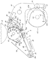
図12は、本発明の第3の実施例を示している。この第3の実施例は第2の実施例と比較すると、プレスローラー136に代えてプレスローラー159を用いる点、再給紙案内部材22に代えて再給紙案内部材160を用いる点、クリーニングローラー137に代えてクリーニング部材161を用いる点においてのみ相違しており、他の構成は同一である。
【0183】
プレスローラー159は金属製の芯部159aにゴム等の弾性体を巻成して構成されており、版胴12の軸方向に延在して設けられている。プレスローラー159は、プレスローラー13,136と同様に芯部159aの両端部を各アーム部材20によって回転自在に支持されており、プレスローラー駆動モーター145によって回転駆動される。プレスローラー159の周面の円周方向長さは版胴12の外周面上における表面領域あるいは裏面領域の円周方向長さよりも長くなるように設定されており、プレスローラー159は少なくともその周面が四フッ化エチレン樹脂等の撥インキ性を有する部材によって構成されている。
【0184】
プレスローラー159の右方に配設された再給紙案内部材160は、各支軸162a,163a上にそれぞれ一体的に設けられそれぞれの周面をプレスローラー159の周面に圧接させた複数のころ状のローラー162,163と、用紙Pをプレスローラー159の周面に沿わせるための曲面状に形成された用紙ガイド板164とを有している。各支軸162a,163aはそれぞれの両端部を各アーム部材20に回転自在に支持されており、図示しない付勢手段によってそれぞれ芯部159aに向けて付勢されている。各ローラー162,163は、対応する支軸162a,163aに、プレスローラー159のほぼ全幅にわたってそれぞれ所定の間隔をもって一体的に取り付けられている。用紙ガイド板164はプレスローラー159の周面から各ローラー162,163の半径よりも小さな距離である所定距離離れた位置に配設されており、その両端部を各アーム部材20に固着されている。用紙ガイド板164は芯部159aを中心とした曲面となるように形成されており、用紙ガイド板164には各ローラー162,163及び後述するクリーニングローラー165の周面をプレスローラー159の周面に当接させるための複数の開口部が形成されている。
【0185】
クリーニング部材161は、図13に示すように、クリーニングローラー165、クリーニングローラー揺動手段166、拭き取りローラー167、ロール保持部材168、シート巻き取り部材169等を有している。
プレスローラー159と同じ幅となるように版胴12の軸方向に延在して設けられたクリーニングローラー165は、図12に示すように再給紙案内部材160と再給紙レジストローラー23との間に配設されており、少なくともその表面はプレスローラー159に接触した際にプレスローラー159からのインキが転移し易い材質であるゴム等によって形成されている。
【0186】
クリーニングローラー165の近傍に配設されたクリーニングローラー揺動手段166は、それぞれ一対の揺動アーム170、ソレノイド171、引張ばね172等を有している。
一対の揺動アーム170は、各アーム部材20間において回転自在に支持された支軸170aの両端部近傍にそれぞれのほぼ中央部を一体的に取り付けられており、それぞれの一端部間においてクリーニングローラー165の支軸165aを回転自在に支持している。各揺動アーム170の他端部には、アーム部材20にそれぞれ取り付けられた一対のソレノイド171のプランジャ171aがそれぞれ取り付けられていると共に、各一端をアーム部材20にそれぞれ固着された一対の引張ばね172の他端がそれぞれ取り付けられている。この構成により、各ソレノイド171が作動されるとクリーニングローラー165はその周面をプレスローラー159の周面から離間させる図13に二点鎖線で示す離間位置を占め、各ソレノイド171の作動が解除されるとクリーニングローラー165は各引張ばね172の付勢力によってその周面をプレスローラー159の周面に圧接させる図13に実線で示す圧接位置を占める。
【0187】
また、一方の揺動アーム170の外面側には図示しないクリーニングローラー駆動モーターが取り付けられており、クリーニングローラー165は図示しないクリーニングローラー駆動モーターからの回転駆動力をギヤ等の図示しない駆動力伝達手段によって伝達されることで、図13に矢印で示すプレスローラー159の回転方向と同方向に、プレスローラー159の回転周速度の10分の1程度の回転周速度で回転駆動される。
【0188】
クリーニングローラー165の右下方近傍には拭き取りローラー167が配設され、その右方にはロール保持部材168とシート巻き取り部材169とが配設されている。クリーニングローラー165と同じ幅を有する拭き取りローラー167はその支軸167aを各アーム部材20に回転自在に支持されており、少なくともその表面はゴム等の高摩擦抵抗部材によって形成されている。支軸167aは図示しない付勢手段によってプレスローラー159に向けて付勢されており、クリーニングローラー165が離間位置を占めたときにクリーニングローラー165の周面と拭き取りローラー167の周面とが所定の圧接力で圧接するように構成されている。
【0189】
ロール保持部材168は各アーム部材20にそれぞれ取り付けられており、クリーニングローラー165の周面に付着したインキを拭き取るクリーニングシート173をロール状に巻成してなるクリーニングシートロール173aを回転自在かつ着脱自在に支持する。クリーニングシートロール173aから引き出されたクリーニングシート173の一端を拭き取りローラー167の周面を介した状態で保持するシート巻き取り部材169は、各アーム部材20間に設けられた図示しないシート巻き取りモーターによって回転駆動されることによりクリーニングシート173を図の矢印方向に巻き取っていく。
【0190】
以下に、第3の実施例における両面印刷装置1の動作を説明する。
片面印刷モード時における原稿読取動作、排版動作、製版動作、給版動作、版付け動作、試し刷り動作、及び印刷動作は、ソレノイド171を作動状態とすることでクリーニングローラー165を離間位置に保持したままとすることを除いて第2の実施例と同様であるのでその説明を省略し、両面印刷モード時における動作のみを説明する。
【0191】
第1及び第2の実施例と同様に両面印刷モードが設定され、用紙厚みが入力された後に製版スタートキー104が押下されると、読取動作、排版動作、製版動作がそれぞれ並行して行われる。そして、排版動作が完了すると給版動作が行われ、版胴12の外周面上に分割製版済みマスタ65が巻装される。給版動作が完了して版胴12がホームポジションで停止すると、カム軸44がカム板138Bをカムフォロア41に対して当接可能となる位置に移動された後、給紙部4から1枚の用紙Pが給送され、給送された用紙Pはその先端をレジストローラー対71に挟持される。製版スタートキー104の押下時において各ソレノイド171は作動状態にあり、クリーニングローラー165は離間位置に保持されている。
【0192】
クランパー19が切換部材10と対応する位置を通過すると切換部材10が第2の位置に変位され、第1製版画像65Aの画像領域先端部がプレスローラー159と対応する位置に到達する所定のタイミングで駆動ローラー71aが回転駆動されて用紙Pが版胴12とプレスローラー159との間に向けて給送される。また、駆動ローラー71aの回転と同時にプレスローラー駆動モーター145が作動され、プレスローラー159が芯部159aを中心に図12において反時計回り方向に回転駆動される。
【0193】
上記所定のタイミングにおいてカム板138Bはその凸部をカムフォロア41から離脱させ、プレスローラー159が印圧ばね42の付勢力によってその周面を版胴12の外周面に圧接させる。これにより第1製版画像65Aに対応した画像が用紙Pの表面に印刷され、分割製版済みマスタ65のうちの第1製版画像65Aが形成された部分の版付けが行われる。版付けにより第1製版画像65Aに応じた画像をその表面に印刷された用紙Pは、第1及び第2の実施例と同様に第2の位置を占めた切換部材10によって再給紙手段9へと案内される。補助トレイ8上に搬送された用紙Pは移動する無端ベルト38により図12の矢印方向へと搬送され、その先端を曲折端部24aに当接させた状態で停留される。
【0194】
プレスローラー159は版胴12の表面領域との接触を終えるとカム板138Bの凸部がカムフォロア41に当接することで離間位置を占め、このときに図示しないプレスローラー係止手段が作動すると共にプレスローラー駆動モーター145の作動が停止されることで回転を停止した状態で離間位置に保持される。その後、カム軸44がカム板138Cをカムフォロア41に対して当接可能となる位置に移動される。
【0195】
プレスローラー接離機構55では、カム板138Cの凸部がカムフォロア41と当接可能な位置までカム軸44が回転すると図示しないプレスローラー係止手段の作動が解除され、クランパー19が再び切換部材10と対応する位置を占めるまでの間に切換部材10が第2の位置から第1の位置に変位される。そして、第2製版画像65Bの画像領域先端部がプレスローラー159と対応する位置に到達するよりもやや早いタイミングである所定のタイミングでプレスローラー駆動モーター145が作動されると共にソレノイド33が作動され、再給紙レジストローラー23が離間位置から圧接位置に揺動されることで先端を曲折端部24aに当接させた状態で停留されていた用紙Pが、版胴12と当接しつつこれと同じ周速度で回転駆動されているプレスローラー159の周面に当接される。
【0196】
再給紙レジストローラー23によりプレスローラー159の周面に当接された用紙Pは、再給紙案内部材160によってプレスローラー159の周面に密着した状態で版胴12との当接部に向けて搬送される。そして、裏面領域の先端部がプレスローラー159と対応する位置に到達するタイミングで、用紙Pは版胴12とプレスローラー159との当接部に送り込まれる。これにより第2製版画像65Bに対応した画像が用紙Pの裏面に印刷され、分割製版済みマスタ65のうちの第2製版画像65Bが形成された部分の版付けが行われる。両面に画像を印刷された用紙Pは、第1の位置を占めた切換部材10によって排紙搬送部材85へと案内された後に排紙トレイ86上に排出される。
【0197】
その後、カム板138Cの凸部がカムフォロア41に当接したときに図示しないプレスローラー係止手段が作動し、プレスローラー159が回転した状態で離間位置に保持される。また、ソレノイド33が作動されてからプレスローラー159が1回転すると、ソレノイド33の作動が解除されると共に各ソレノイド171の作動が解除され、再給紙レジストローラー23が離間位置を占めると共にクリーニングローラー165が圧接位置を占める。そして、図示しないクリーニングローラー駆動モーターが作動してクリーニングローラー165が回転駆動された後にプレスローラー159が1回転すると、プレスローラー駆動モーター145の作動が停止されると共に各ソレノイド171が作動される。各ソレノイド171が作動されてクリーニングローラー165が離間位置を占めると図示しないシート巻き取りモーターが作動され、シート巻き取り部材169が回転駆動されることでクリーニングシート173が回転駆動されているクリーニングローラー165の周面に接触しつつ図13の矢印方向に所定量だけ送られる。この間に版胴12はホームポジションまで回転して停止し、版胴12、プレスローラー159、クリーニングローラー165、シート巻き取り部材169の停止後、両面印刷装置1は版付け動作を終えて印刷待機状態となる。
【0198】
上述の版付け時において、再給紙手段9からの用紙Pの再給紙時に、用紙Pの印刷面と接触することでプレスローラー159の表面に用紙Pからのインキが再転移するが、プレスローラー159の周面が撥インキ性を有すると共に所定のタイミングで接離動作及び回転駆動されるクリーニングローラー165がプレスローラー159の周面をクリーニングするので、用紙Pからプレスローラー159の周面への再転移インキ量が減少されると共にプレスローラー159の周面からの再転移インキの除去が促進され、以下の印刷時においてプレスローラー159から用紙Pの裏面へのインキの再転移を防止できる。また、クリーニングローラー165の周面もクリーニングシート173によってクリーニングされるので、クリーニングローラー165が常に清浄な状態でプレスローラー159のクリーニングを行うことができ、インキの再転移を効果的に防止することができる。
【0199】
版付け動作完了後、印刷速度設定キー113及び操作パネル103上の各種キーによって印刷条件が入力された後に試し刷りキー106が押下されることにより試し刷りが行われる。試し刷りキー106が押下されると、カム板138Bがカムフォロア41に当接可能となる位置にカム軸44が移動された後に図示しないプレスローラー係止手段の作動が解除され、設定された印刷速度で版胴12が回転駆動されると共に切換部材10が第2の位置に位置決めされる。そして、給紙部4から1枚の用紙Pが給送されると共にプレスローラー159が回転駆動され、給送された用紙Pは版付け時と同じタイミングで印刷部2へと送られてその表面に第1製版画像65Aに対応した画像を印刷される。画像を印刷された用紙Pは切換部材10によって補助トレイ8へと案内され、その先端を曲折端部24aに当接させた状態で停留される。この間、各ソレノイド171は作動状態にあり、クリーニングローラー165は離間位置に保持されている。
【0200】
その後、図示しないプレスローラー係止手段が作動してプレスローラー159が離間位置で保持されると共にプレスローラー駆動モーター145の作動が停止され、カム板138Cがカムフォロア41に対して当接可能となる位置にカム軸44が移動された後、図示しないプレスローラー係止手段の作動が解除される。切換部材10は、クランパー19が再び切換部材10と対応する位置を占めるまでの間に第2の位置から第1の位置に変位される。
【0201】
そして、版付け時と同じタイミングでプレスローラー駆動モーター145が作動されると共にソレノイド33が作動され、再給紙レジストローラー23が離間位置から圧接位置へと変位されて用紙Pがプレスローラー159の周面に当接される。用紙Pはプレスローラー159の回転力によって搬送され、再給紙案内部材160によってプレスローラー159の周面に密着した状態で印刷部2へと搬送される。搬送された用紙Pは回転駆動されつつ揺動するプレスローラー159によって第2製版画像65Bに圧接され、その両面に画像を印刷された用紙Pは切換部材10によって排紙搬送部材85へと案内された後、排紙トレイ86上に排出される。
【0202】
その後、カム板138Cの凸部がカムフォロア41に当接したときに図示しないプレスローラー係止手段が作動し、プレスローラー159が回転した状態で離間位置に保持された後、版付け時と同様にソレノイド33の作動が解除されると共に各ソレノイド171の作動が解除され、再給紙レジストローラー23が離間位置を占めると共にクリーニングローラー165が圧接位置を占める。そして、図示しないクリーニングローラー駆動モーターが作動してクリーニングローラー165が回転駆動された後にプレスローラー159が1回転すると、プレスローラー駆動モーター145の作動が停止されると共に各ソレノイド171が作動されクリーニングローラー165が離間位置に変位される。クリーニングローラー165が離間位置を占めると図示しないシート巻き取りモーターが作動され、クリーニングシート173が回転駆動されているクリーニングローラー165の周面に接触しつつ図13の矢印方向に所定量だけ送られる。この間に版胴12はホームポジションまで回転して停止し、版胴12、プレスローラー159、クリーニングローラー165、シート巻き取り部材169の停止後、両面印刷装置1は試し刷り動作を終えて再び印刷待機状態となる。
【0203】
試し刷り動作後、テンキー109によって印刷枚数が入力された後に印刷スタートキー105が押下されると、第1及び第2の実施例と同様に印刷動作が行われる。本実施例では、印刷枚数としてN枚が入力された場合を説明する。
印刷スタートキー105が押下されると、版付け時及び試し刷り時と同様に、カム板138Bがカムフォロア41に当接可能となる位置にカム軸44が移動された後に図示しないプレスローラー係止手段の作動が解除され、設定された印刷速度で版胴12が回転駆動されると共に切換部材10が第2の位置に位置決めされる。そして、給紙部4から1枚目の用紙P1が給送されると共にプレスローラー159が回転駆動され、用紙P1は印刷部2においてその表面に第1製版画像65Aに対応した画像を印刷される。表面に画像を印刷された用紙P1は切換部材10によって補助トレイ8へと案内され、その先端を曲折端部24aに当接させた状態で停留される。
【0204】
その後、図示しないプレスローラー係止手段が作動してプレスローラー159が離間位置で保持されると共にプレスローラー駆動モーター145の作動が停止され、カム板138Aがカムフォロア41に対して当接可能となる位置にカム軸44が移動された後、プレスローラー駆動モーター145が作動されると共に図示しないプレスローラー係止手段の作動が解除される。また、この動作とほぼ同時に給紙部4から2枚目の用紙P2が給送され、用紙P2はレジストローラー対71で一時停留された後に用紙P1と同じタイミングで印刷部2に向けて送られる。切換部材10はクランパー19との衝突を回避すべく第1の位置に位置決めされた後、クランパー19の通過後に再び第2の位置に位置決めされる。
【0205】
給送された用紙P2はプレスローラー159によって第1製版画像65Aに圧接され、表面に画像を印刷された後に第2の位置を占めた切換部材10によって補助トレイ8上に案内される。このとき試し刷り時と同じタイミングでソレノイド33が作動され、補助トレイ8上に停留されていた用紙P1がプレスローラー159の回転力によって印刷部2へと送られる。用紙P1は用紙P2の後端が版胴12とプレスローラー159との当接部を抜けきった後、版胴12の裏面領域がプレスローラー159と対向するタイミングで版胴12とプレスローラー159との当接部に送られ、プレスローラー159によって第2製版画像65Bに圧接されることでその裏面に画像を印刷される。
【0206】
上述の動作中、版胴12の中間領域がプレスローラー159と対向する位置を占める直前にソレノイド123が作動され、切換部材10が第2の位置から第1の位置に変位される。これにより切換部材10によって案内されていた用紙P2の後端は、切換部材10の下面10aとプレスローラー159の周面との間の僅かな隙間を通って補助トレイ8上に案内され、これに続いて搬送された用紙P1の先端は、切換部材10の上面10bに沿って排紙搬送部材85へと案内される。用紙P1は、剥離爪84によって分割製版済みマスタ65より剥離された後に排紙搬送部材85によって搬送され、排紙トレイ86上に排出される。
【0207】
また、ソレノイド33が作動されてからプレスローラー159が1回転するとソレノイド33及び各ソレノイド171の作動がそれぞれ解除され、再給紙レジストローラー23が離間位置を占めると共にクリーニングローラー165が圧接位置を占める。そして、図示しないクリーニングローラー駆動モーターが作動してクリーニングローラー165が回転駆動された後にプレスローラー159が1回転すると、プレスローラー駆動モーター145の作動が停止されると共に各ソレノイド171が作動される。各ソレノイド171が作動されてクリーニングローラー165が離間位置を占めると図示しないシート巻き取りモーターが作動され、シート巻き取り部材169が回転駆動されることでクリーニングシート173が回転駆動されているクリーニングローラー165の周面に接触しつつ図13の矢印方向に所定量だけ送られる。そして、クリーニングシート173が所定量送られると、図示しないクリーニングローラー駆動モーター及び図示しないシート巻き取りモーターの作動がそれぞれ停止される。
【0208】
その後、給紙部4から3枚目の用紙P3が給送され、用紙P3はレジストローラー対71で一時停留された後に用紙P1と同じタイミングで印刷部2に向けて送られる。切換部材10はクランパー19との衝突を回避すべく第1の位置に位置決めされ、クランパー19の通過後に再び第2の位置に位置決めされる。給送された用紙P3は表面に画像を印刷された後、第2の位置を占めた切換部材10によって補助トレイ8上に案内される。そして所定のタイミングでソレノイド33が作動され、補助トレイ8上に停留されていた用紙P2が印刷部2へと搬送される。用紙P2は用紙P1と同様のタイミングで版胴12とプレスローラー159との当接部に送られ、その裏面に画像を印刷される。切換部材10は上述と同様のタイミングで第2の位置から第1の位置に変位され、用紙P3の後端は下面10aとプレスローラー159の周面との間の僅かな隙間を通って補助トレイ8上に案内される。また、これに続いて補助トレイ8上より搬送された用紙P2の先端は上面10bに沿って排紙搬送部材85へと案内され、用紙P2は剥離爪84によって分割製版済みマスタ65より剥離された後に排紙搬送部材85によって搬送されて排紙トレイ86上に排出される。
【0209】
この動作中にも上述と同じタイミングでソレノイド33及び各ソレノイド171の作動がそれぞれ解除され、再給紙レジストローラー23が離間位置を占めると共にクリーニングローラー165が圧接位置を占める。そして、上述と同じタイミングでプレスローラー駆動モーター145の作動が停止されると共に各ソレノイド171が作動され、図示しないシート巻き取りモーターが作動されてシート巻き取り部材169が回転駆動されることにより、クリーニングシート173が回転駆動されているクリーニングローラー165の周面に接触しつつ図13の矢印方向に送られる。クリーニングシート173が所定量送られると、図示しないクリーニングローラー駆動モーター及び図示しないシート巻き取りモーターの作動がそれぞれ停止される。以下、このクリーニングローラー165の揺動動作及び回転動作、並びにシート巻き取り部材169の回転動作が印刷終了まで同じタイミングで繰り返される。
【0210】
以下、上述と同様の印刷動作が(N−1)枚目まで行われる。そして、N枚目の用紙PNが給紙部4から給送されその表面に第1製版画像65Aに対応した画像を印刷されて補助トレイ8上に案内された後、(N−1)枚目の用紙P(N−1)がその裏面に第2製版画像に対応した画像を印刷されて排紙トレイ86上に排出されると、図示しないプレスローラー係止手段が作動してプレスローラー159が離間位置で保持されると共にプレスローラー駆動モーター145の作動が停止され、カム板138Cがカムフォロア41に対して当接可能となる位置にカム軸44が移動された後、プレスローラー駆動モーター145が作動されると共に図示しないプレスローラー係止手段の作動が解除される。このとき切換部材10は第1の位置を占めた状態を維持している。
【0211】
そして、第2製版画像65Bの画像領域先端部がプレスローラー159と対応する位置に到達するよりもやや早いタイミングでソレノイド33が作動され、揺動アーム32が支軸32aを中心に図9における時計回り方向に揺動される。これにより再給紙レジストローラー23が離間位置から圧接位置に揺動され、先端を曲折端部24aに当接させた状態で停留されていた用紙PNがプレスローラー駆動モーター145によって回転駆動されているプレスローラー159の周面に当接される。その後、第2製版画像65Bの画像領域先端部がプレスローラー159と対応する位置に到達するタイミングでカム板138Cがその凸部をカムフォロア41から離脱させ、プレスローラー159が印圧ばね42の付勢力によってその周面を版胴12の外周面に圧接させることにより、用紙PNはその裏面に画像を印刷される。
【0212】
両面に画像を印刷された用紙PNは上面10bに沿って排紙搬送部材85へと案内され、剥離爪84によって分割製版済みマスタ65より剥離された後に排紙搬送部材85によって搬送されて排紙トレイ86上に排出される。プレスローラー159は、版胴12の裏面領域との接触を終えるとカム板138Cの凸部がカムフォロア41に当接することで離間位置を占め、このときに図示しないプレスローラー係止手段が作動することで離間位置に回転した状態で保持される。また、上述と同じタイミングでソレノイド33及び各ソレノイド171の作動がそれぞれ解除されて再給紙レジストローラー23が離間位置を占めると共にクリーニングローラー165が圧接位置を占め、上述と同じタイミングでプレスローラー駆動モーター145の作動が停止されると共に各ソレノイド171が作動され、さらに図示しないシート巻き取りモーターが作動されてシート巻き取り部材169が回転駆動されることにより、クリーニングシート173が回転駆動されているクリーニングローラー165の周面に接触しつつ図13の矢印方向に送られる。この間に版胴12がホームポジションまで回転して停止し、版胴12、プレスローラー159、クリーニングローラー165、シート巻き取り部材169の停止後、両面印刷装置1は印刷動作を終えて再び印刷待機状態となる。
【0213】
第3の実施例によれば、再給紙レジストローラー23と再給紙案内部材160との間にクリーニングローラー165を配置することで、第1及び第2の実施例に比してクリーニング部材161の設置スペースを大きく取ることができ、クリーニング部材としてより良好なクリーニング性能を持ったものを採用することが可能となり、プレスローラー周面から用紙へのインキの再転移をより効果的に防止することで良質な両面印刷物を得ることができる。
【0214】
第2及び第3の実施例では、プレスローラー回転駆動手段139を構成するプレスローラー駆動モーター145によってプレスローラー136あるいはプレスローラー159を回転駆動する構成としたが、プレスローラー駆動モーター145を用いずに版胴駆動手段121の回転駆動力をギヤやベルト等の図示しない駆動力伝達手段によって伝達し、プレスローラー136あるいはプレスローラー159を回転駆動する構成としてもよい。
【0215】
図14は、本発明の第3の実施例の変形例に用いられるクリーニング部材174を示している。このクリーニング部材174は、第3の実施例で示したクリーニング部材161と比較すると、拭き取りローラー167、ロール保持部材168、シート巻き取り部材169、及びクリーニングシート173に代えて、塗布ローラー175、クリーナー貯容部材176を用いる点においてのみ相違しており、他の構成は同一である。
【0216】
塗布ローラー175は耐インキ腐食性及び耐クリーナー性を有する材料、例えばシリコーン樹脂製のスポンジゴム等から構成されており、クリーニングローラー165と同じ幅となるように形成されている。塗布ローラー175は一体的に構成された支軸175aをクリーナー貯容部材176に回転自在に支持されており、アーム部材20に取り付けられた図示しない塗布ローラー駆動モーターによって図の矢印方向にクリーニングローラー165の回転周速度とほぼ同じ周速度で回転駆動される。
【0217】
内部にクリーナー溶液177を貯容する箱形のクリーナー貯容部材176は各アーム部材20間に設けられた図示しないブラケットに取り付けられており、その取付位置はクリーニングローラー165が離間位置を占めたときにクリーニングローラー165と塗布ローラー175とが所定の圧接力で圧接する位置に定められている。内部に貯容されるクリーナー溶液177としては、例えば中性洗剤溶液、アルコール、ベンジン、灯油、軽油、ガソリン等の石油類等が主に用いられる。
【0218】
このようなクリーニング部材174を用い、クリーニングローラー揺動手段166によってクリーニングローラー165を揺動させてその周面を塗布ローラー175の周面に圧接させ、各ローラー165,175をそれぞれ同方向に回転駆動することにより、クリーニングローラー165の周面に付着したインキがクリーナー溶液177を含んだ塗布ローラー175によって清浄化することにより、第3の実施例と同等の作用効果を得ることができる。
【0219】
第3の実施例及び変形例では、プレスローラー159としてその周面の円周方向長さが単に版胴12の外周面上における表面領域あるいは裏面領域の円周方向長さよりも長いものを用いたが、この条件を満たすと共にその円周方向長さと版胴12の円周方向長さとが整数比となるもの、すなわちその直径と版胴12の直径とが整数比となるものを用いてもよい。このような構成とすることにより、プレスローラーの周速度を版胴12の周速度と同速度とすることが簡単になると共にプレスローラーが常に同じ位置で版胴12の外周面と接することとなるため、第3の実施例のように版胴12の1回転毎にプレスローラーのクリーニング動作を行う必要がなくなり、動作制御を簡略化できる。この場合、プレスローラーとしてその円周方向長さが版胴外周面上における表面領域あるいは裏面領域の円周方向長さよりも長いものである必要があるため、プレスローラーの直径と版胴の直径との比は1:2または1:3が望ましい。比がこれよりも大きいと版胴の直径が大きくなりすぎ、装置の小型化の妨げとなる。このことからプレスローラーの直径は版胴の直径の2分の1ないし3分の1の範囲内にあることが望ましい。
【0220】
上記各実施例及び変形例では、表面印刷済みの片面印刷用紙を補助トレイ8上から再給紙する再給紙レジスト部材として、プレスローラー13,136,159の周面に対して接離自在かつ回転自在な再給紙レジストローラー23を用いた例を示したが、再給紙レジスト部材としてはこれに限られず、例えばプレスローラー13,136,159の周面に対して接離自在であってその当接部分が丸く形成された板状部材等を用いてもよい。
【0221】
本発明によれば、片面印刷時には製版済みマスタを版胴に巻装し、給紙部より用紙を給送してこれをプレスローラーによって版胴に圧接させるので、マスタを無駄に使用することなく通常の孔版印刷装置と同様に片面印刷を行うことができる。また、両面印刷時には分割製版済みマスタを版胴に巻装し、給紙部より1枚目の用紙を給送してこの表面をプレスローラーによって版胴に圧接させた後に補助トレイ上に排出し、給紙部より2枚目の用紙を給送してこの表面をプレスローラーによって版胴に圧接させた後に補助トレイ上に排出すると共に、再給紙手段によって1枚目の用紙を反転給送してこの裏面をプレスローラーによって版胴に圧接させた後に排紙トレイ上に排出するので、用紙に印刷される表面画像及び裏面画像が共にプレスローラーにより版胴から転移されるインキによって形成され、良好な両面印刷物を得ることができる。
【0222】
また、印刷部の構成が版胴とこれよりも小径のプレスローラーとからなり、補助トレイが排紙部を構成する排紙搬送部材の下方に配設されているので、通常の片面印刷用の孔版印刷装置に比して大幅に大型化することなく装置を構成でき、設置スペースの増大を抑制することができる。
【図面の簡単な説明】
【図1】本発明の第1の実施例を採用した両面印刷装置の概略正面図である。
【図2】本発明の第1の実施例における版胴外周面から離間したプレスローラーを示す概略正面図である。
【図3】本発明の第1の実施例における版胴外周面に接触したプレスローラーを示す概略正面図である。
【図4】本発明の第1の実施例に用いられるプレスローラー接離機構を説明する概略図である。
【図5】本発明の第1の実施例に用いられる分割製版済みマスタを説明する概略図である。
【図6】本発明の第1の実施例に用いられる製版済みマスタを説明する概略図である。
【図7】本発明の第1の実施例に用いられる操作パネルを示す概略図である。
【図8】本発明の第1の実施例に用いられる制御手段のブロック図である。
【図9】本発明の第2の実施例を示す印刷部要部の概略正面図である。
【図10】本発明の第1または第2の実施例の変形例に用いられる再給紙案内部材を説明する概略図である。
【図11】本発明の第1または第2の実施例の他の変形例に用いられる再給紙案内部材を説明する概略図である。
【図12】本発明の第3の実施例を示す印刷部要部の概略正面図である。
【図13】本発明の第3の実施例に用いられるクリーニング部材を説明する概略図である。
【図14】本発明の第3の実施例の変形例に用いられるクリーニング部材を説明する概略図である。
【符号の説明】
1 両面印刷装置
2 印刷部
3 製版部
4 給紙部
6 排紙部
8 補助トレイ
9 再給紙手段
10 切換部材
12 版胴
13 プレスローラー
20 プレスローラー支持部材(アーム部材)
22,151,155,160 再給紙案内部材
23 再給紙レジスト部材(再給紙レジストローラー)
24 再給紙位置決め部材
25 再給紙搬送部材
28,29,30 ローラー
32 再給紙レジスト支持部材(揺動アーム)
40 再給紙レジスト接離機構
55 プレスローラー接離機構
65 分割製版済みマスタ
65A 第1製版画像
65B 第2製版画像
66 製版済みマスタ
66A 第3製版画像
120 第1表示手段、第2表示手段(LCDからなる表示装置)
139 プレスローラー回転駆動手段
150 駆動力伝達手段
152,153 2個のローラー(ローラー)
154 無端ベルト
156 板部材(用紙ガイド板)
161,174 クリーニング部材
P 用紙
S 所定の空白部[0001]
BACKGROUND OF THE INVENTION
The present invention relates to a printing apparatus, and more particularly to a structure of a double-sided printing apparatus capable of printing on both sides of a sheet in one process.
[0002]
[Prior art]
Conventionally, digital thermal stencil printing is known as a simple printing method. In this stencil printing apparatus, a thermal head in which fine heating elements are arranged in a row is brought into contact with a thermal stencil master (hereinafter referred to as “master”), and the master is conveyed while energizing the heating elements in a pulsed manner. According to the information, the master is heated and melt-pierced, and after the master is wound around the outer peripheral surface of the porous cylindrical plate cylinder, the outer peripheral surface of the plate cylinder is pressed by pressing means such as a press roller through the paper. The ink is transmitted from the master punching portion and transferred to the paper to obtain a printed image.
[0003]
In this stencil printing, in recent years, double-sided printing, in which printing is performed on both sides of a sheet, has been frequently performed for the purpose of reducing paper consumption and document storage space. This double-sided printing is a conventional method in which the paper stacked on the paper feed unit is passed through the printing unit, printed on one side, then turned over, and again passed through the printing unit to print on the other side. Although a double-sided printed material has been obtained, there is a problem that it is troublesome to set the paper once ejected to the paper feeding unit or to align the paper after single-sided printing.
[0004]
In addition, since the printed matter after printing is not sufficiently dry, there is a problem that if you try to print on the back side immediately, the transport roller, press roller, etc. will be pressed against the image part and the printed image will be stained or disturbed In many cases, the printing on the back side was performed after several hours or more. In particular, when there is a solid image portion, drying for a long time is necessary, and printing is performed on the back surface on the next day.
In this way, in double-sided printing, the paper must be dried for a long time before printing on the other side after printing on one side, and because the paper is passed through the printing section twice, the single-sided printing is performed even in the net printing time. It took twice as much time as that, and it took too much time.
[0005]
In order to solve the above-described problems, the first plate cylinder, the second plate cylinder disposed opposite to the first plate cylinder via the paper conveyance path, the outer peripheral surface of the first plate cylinder, and the second A stencil printing apparatus is provided with contact / separation means for contacting and separating the outer peripheral surface of each plate cylinder from each other, and by operating the contact / separation means to press-contact each plate cylinder to each other to obtain a double-sided printed matter in one step. No. 6-71996 and JP-A-6-135111.
[0006]
A first pressing cylinder, a first pressing means disposed opposite to the first printing cylinder via the paper conveyance path and provided so as to be able to be pressed against and separated from the first printing cylinder; A second plate cylinder disposed on the downstream side of the plate cylinder in the sheet conveying direction and facing the first plate cylinder via the sheet conveying path, and opposed to the second plate cylinder via the sheet conveying path And a second pressing means arranged so as to be capable of being pressed and separated from the second plate cylinder. After the first printing cylinder and the first pressing means are pressed, the second plate Japanese Patent Laid-Open Nos. 8-90893 and 8-142477 disclose a stencil printing apparatus that obtains a double-sided printed material in one step by bringing a cylinder and second pressing means into pressure contact with each other.
[0007]
Furthermore, using a divided master-making master in which the first plate-making image and the second plate-making image are arranged in two directions in the rotation direction of the plate cylinder, the press roller is directly applied to the plate cylinder corresponding to the image area of one of the plate-making images. A first step of transferring the first printing image corresponding to one plate-making image to the outer peripheral surface of the press roller by rotating together with the plate cylinder while abutting, and an image area of the other plate-making image and the first printing after the first step In order to correspond to the image, the press roller is brought into contact with the plate cylinder through the paper and rotated together with the plate cylinder to retransfer the first print image to the first surface corresponding to the press roller of the paper, A stencil printing method for obtaining a double-sided printed material in one step by a second step of transferring a second printed image corresponding to the other plate-making image onto a second surface corresponding to the plate cylinder of the paper, and a stencil printing apparatus for performing the same Japanese Patent Laid-Open No. 8-332768 Which is incorporated herein by reference.
[0008]
[Problems to be solved by the invention]
However, in the techniques disclosed in Japanese Patent Laid-Open Nos. 6-71996 and 6-135111, two plate cylinders are arranged vertically so that they are pressed against each other. The plate cylinders need to be pressed against each other, and the master for making the plate must be wound on one of the plate cylinders, and the master not yet made on the other plate cylinder. There is a problem of being done. Further, in order to press the two plate cylinders each having a clamper for holding the master on the outer peripheral surface, it is necessary to separate the plate cylinders at positions where the respective clampers face each other. As a result, the area where the plate cylinders contact each other is reduced and the image area is reduced. In addition, there is a problem that a large noise is generated when each plate cylinder contacts.
[0009]
In the techniques disclosed in JP-A-8-90893 and JP-A-8-142477, it is necessary to wind an unprocessed master around one plate cylinder during single-sided printing as described above, and the master is useless. There is a problem of being consumed. In addition, since the two plate cylinders are arranged in series in the paper conveyance direction, the size of the device is almost twice as large as that of a stencil printing device for single-sided printing, and it is difficult to secure the installation space. There is.
[0010]
In the technique disclosed in Japanese Patent Application Laid-Open No. 8-332768, either one of the first plate-making image and the second plate-making image (front image and back image) is directly transferred from the plate cylinder to the paper, and the other is a press roller. Therefore, there is a problem that the image density on the paper is different between the front surface and the back surface.
[0011]
The present invention solves the above-mentioned problems, can perform single-sided printing without using a useless master, can obtain printed matter with good image quality during double-sided printing, and can further suppress an increase in installation space. An object of the present invention is to provide a one-step duplex printing apparatus.
[0012]
[Means for Solving the Problems]
According to the first aspect of the present invention, there is provided a plate cylinder for winding a divided plate-making master in which two first plate-making images and second plate-making images are arranged in the length direction on an outer peripheral surface, and a contact with the plate cylinder. A printing unit having a press roller provided in a separable manner, a paper feeding unit that feeds paper toward the printing unit, and a paper discharge unit that discharges printed paper that has been printed in the printing unit to the outside. And an auxiliary tray for temporarily storing the surface-printed paper having a printed image formed on the surface thereof in the printing unit, and the surface-printed paper stored on the auxiliary tray along the outer peripheral surface of the press roller. A sheet re-feeding unit that re-feeds the printing unit toward the printing unit, and a switching member that guides the paper that has passed through the printing unit to either the auxiliary tray or the paper discharge unit. , Print the first sheet from the paper feed unit The first plate-making image or the second plate-making image is printed on the surface thereof, and the printed first sheet is guided to the auxiliary tray by the switching member, and then the paper feeding unit Then, the second sheet is fed to the printing unit to print either the first plate-making image or the second plate-making image on the surface thereof, and the first sheet is fed to the printing unit by the refeeding unit. And the other one of the first plate-making image and the second plate-making image is printed on the back surface thereof, and the first sheet is fed to the paper discharge section by the switching member, and the second sheet is fed to the auxiliary unit. Each of the paper refeeding means is guided by a tray, and the refeeding means is transported by a refeeding transporting member that transports the surface-printed paper stored on the auxiliary tray toward the press roller, and the refeeding transporting member. The printed paper with the printed surface is placed in front of the press roller. A re-feed positioning member that pauses at a fixed position, and a re-feed resist member that makes the surface-printed paper temporarily stopped at a predetermined position by the re-feed positioning member contact the rotating press roller at a predetermined timing And the surface-printed paper that is brought into contact with the rotating press roller by the re-feeding resist member and conveyed by the rotational force of the press roller is brought into contact with the peripheral surface of the press roller toward the plate cylinder And a refeed guide member for guiding.
[0015]
Claim The invention described in claim 2 is claimed in claim 1. In the double-sided printing apparatus described above, the auxiliary tray is further disposed below the paper discharge unit.
[0016]
Claim The invention according to claim 3 is the first or second aspect. The double-sided printing apparatus according to claim 1, further comprising: a press roller support member that rotatably supports the press roller; and a press roller contact / separation mechanism that swings the press roller support member to contact / separate the press roller with respect to the plate cylinder. A refeed resist support member that supports the refeed resist member, and the refeed resist support member is swingably provided on the press roller support member and supports the refeed resist support A double-sided printing apparatus, comprising: a re-feeding resist contact / separation mechanism that swings a member to bring the re-feeding resist member into and out of contact with the press roller.
[0017]
Claim The invention according to claim 4 is claimed in claim 3. In the double-sided printing apparatus described above, the press roller contact / separation mechanism further includes the first plate making image or the second plate making image contacting the peripheral surface of the press roller during the first rotation of the plate cylinder immediately after the start of printing. The press roller is separated from the plate cylinder so as to prevent the final rotation of the plate cylinder just before the end of printing, and either the first plate-making image or the second plate-making image does not contact the peripheral surface of the press roller. Thus, the press roller is separated from the plate cylinder.
[0018]
Claim The invention according to claim 5 is characterized in that claims 1 to 4 are provided. In the double-sided printing apparatus according to any one of the above, the refeed guide member further includes a rotatable roller in contact with the press roller, and the roller is rotatably supported by the press roller support member. It is characterized by being.
[0019]
Claim The invention according to claim 6 provides claims 1 to 4. In the double-sided printing apparatus according to any one of the above, the re-feeding guide member further includes two rollers and an endless belt that is stretched between the rollers and is in contact with the press roller. The press roller support member is rotatably supported.
[0020]
Claim The invention according to claim 7 provides claims 1 to 4. The double-sided printing apparatus according to any one of the above, wherein the refeed guide member is a plate member that is in contact with the press roller, and the plate member is supported by the press roller support member. And
[0021]
Claim The invention according to claim 8 is the first to seventh aspects of the invention. The double-sided printing apparatus according to any one of the above, further comprising a cleaning member that cleans the peripheral surface of the press roller.
[0022]
Claim The invention according to claim 9 is claim 8. The double-sided printing apparatus described above is further characterized in that the cleaning member is provided so as to be able to contact with and separate from a peripheral surface of the press roller.
[0023]
Claim The invention according to claim 10 is the ninth aspect. The double-sided printing apparatus described above is characterized in that the cleaning member occupies a position separated from the peripheral surface of the press roller during single-sided printing.
[0024]
Claim The eleventh aspect of the present invention is the first to seventh aspects. In the double-sided printing apparatus according to any one of the above, the press roller is further rotationally driven by the press roller rotational driving means at a peripheral speed substantially the same as the peripheral speed of the plate cylinder.
[0025]
Claim The invention described in item 12 is claimed in claim 11. The double-sided printing apparatus described above is characterized in that the press roller is driven to rotate by a rotational force from the plate cylinder at the time of contact with the plate cylinder.
[0026]
Claim The invention described in item 13 is claimed in claim 11 or 12. In the double-sided printing apparatus described above, the press roller rotation driving unit further includes a driving force transmission unit that prevents a change in phase due to rotation of the press roller when the press roller swings.
[0027]
Claim The invention according to claim 14 is claim 13. The double-sided printing apparatus described above is further characterized in that the diameter of the press roller is in the range of one-half to one-third of the diameter of the plate cylinder.
[0028]
Claim The invention according to claim 15 is claimed in claims 11 to 14. The double-sided printing apparatus according to any one of the above, further comprising a cleaning member that cleans the peripheral surface of the press roller.
[0029]
Claim The invention according to claim 16 is the claim 15. The double-sided printing apparatus described above is further characterized in that the cleaning member is provided so as to be able to contact with and separate from a peripheral surface of the press roller.
[0030]
Claim The invention according to claim 17 is the sixteenth aspect. In the double-sided printing apparatus described above, the cleaning member occupies a position separated from the peripheral surface of the press roller during single-sided printing.
[0031]
Claim The invention according to claim 18 is the sixteenth or seventeenth aspect. In the double-sided printing apparatus described above, the cleaning member is further disposed at a position between the refeed resist member and the refeed guide member, and the cleaning member receives the surface-printed paper by the refeed resist member. While being conveyed, it occupies a position separated from the peripheral surface of the press roller.
[0032]
Claim The nineteenth invention is claimed in claim 18. The double-sided printing apparatus described above is characterized in that the length of the peripheral surface of the press roller is longer than the length of the first plate-making image or the second plate-making image.
[0033]
Claim The invention according to claim 20 provides claims 1 to 19. In the double-sided printing apparatus according to any one of the above, the press roller further has an ink repellency on a peripheral surface thereof.
[0034]
Claim The invention according to claim 21 is the invention according to claims 1 to 20. The double-sided printing apparatus according to any one of the above, further comprising first display means for displaying a warning when thick paper is set in the paper feeding unit.
[0035]
Claim According to the twenty-second aspect of the present invention, claims 1 to 21 are provided. In the double-sided printing apparatus according to any one of the above, a second warning is issued when the size of the paper set in the paper feeding unit and the image area size of the first platemaking image and the second platemaking image do not match. It has a display means.
[0036]
Claim The invention according to claim 23 is claimed in claims 1 to 22. In the double-sided printing apparatus according to any one of the above, the divided plate-making is further completed Master making master It has the plate-making part.
[0037]
Claim The invention according to claim 24 is claimed in claim 23. In the double-sided printing apparatus described above, the plate-making unit further includes a predetermined blank portion between the first plate-making image and the second plate-making image when making the divided plate-making master.
[0038]
Claim The invention according to claim 25 is claimed in claim 23 or 24. In the double-sided printing apparatus described above, the plate-making unit further makes a plate-making image as a plate-making image to be printed on the back side of the paper when making the divided plate-making master.
[0039]
Claim The invention according to claim 26 provides claims 23 to 25. In the double-side printing apparatus according to any one of the above, when image data having a size exceeding the image areas of the first plate-making image and the second plate-making image is input as image data to be plate-making at the time of double-side printing. And a function for assisting the operation by giving a warning and guiding the rotation or reduction of the image data.
[0040]
Claim The invention according to claim 27 provides claims 23 to 26. In the double-sided printing apparatus according to any one of the above, image data to be subjected to plate making at the time of double-sided printing is continuously input, and plate-making and printing of the divided plate-making master are repeatedly performed to produce a double-sided printed material of a plurality of pages. At the time of obtaining, when the number of image data is an odd number, a blank page is added to the last page, and plate making and printing operations similar to those in double-sided printing are performed.
[0041]
【Example】
FIG. 1 shows a duplex printing apparatus employing a first embodiment of the present invention. In FIG. 1, a duplex printing apparatus 1 includes a printing unit 2, a plate making unit 3, a paper feeding unit 4, a plate discharging unit 5, a paper discharging unit 6, an image reading unit 7, an auxiliary tray 8, a refeed unit 9, a switching member 10, and the like. have.
[0042]
The printing unit 2 disposed almost at the center of the printing apparatus main body 11 includes a plate cylinder 12 and a press roller 13.
The plate cylinder 12 includes a pair of flanges (not shown) that are rotatably supported by a support shaft 14 that also serves as an ink supply pipe, a porous support plate (not shown) wound around the outer peripheral surface of each flange, and a porosity (not shown). It is mainly composed of a mesh screen (not shown) wound around the outer peripheral surface of the support plate, and is configured to be rotationally driven by the plate cylinder driving means 121 (see FIG. 8) and to be detachable from the printing apparatus main body 11. Has been. In the present embodiment, the plate cylinder 12 has a size capable of obtaining a maximum A3 size printed material during single-sided printing.
[0043]
An ink supply means 15 is disposed inside the plate cylinder 12. The ink supply means 15 includes a support shaft 14, an ink roller 16, a doctor roller 17, and the like.
The ink roller 16 is rotatably supported between side plates (not shown) provided in the plate cylinder 12, and its peripheral surface is disposed in the vicinity of the inner peripheral surface of the plate cylinder 12. 12 is rotated in the same direction. The doctor roller 17 is also rotatably supported between the side plates, and the peripheral surface thereof is disposed in the vicinity of the peripheral surface of the ink roller 16 and is rotationally driven in a direction opposite to the plate cylinder 12 by a driving means (not shown). . A plurality of small holes are formed in the support shaft 14, and the ink supplied from the support shaft 14 is collected in a wedge-shaped space formed in the vicinity of the ink roller 16 and the doctor roller 17. A reservoir 18 is formed.
[0044]
On the outer peripheral surface of the plate cylinder 12, a stage portion (not shown) that forms a plane along one generatrix of the plate cylinder 12 is formed, and on this, the tip of the master is held on the outer peripheral surface of the plate cylinder 12. A clamper 19 is provided. The clamper 19 is opened and closed by opening / closing means (not shown) when the plate cylinder 12 is rotated to a predetermined position.
[0045]
A press roller 13 is disposed below the plate cylinder 12. The press roller 13 is configured by winding an elastic body such as rubber around a metal core 13 a and is provided to extend in the axial direction of the plate cylinder 12. As shown in FIG. 2, the press roller 13 is rotatably supported by a pair of arm members 20 serving as press roller support members at both ends of the core portion 13a. Each arm member 20 having an approximately L-shape is integrated by a swing shaft 21 attached to a portion near the bent portion, and the swing shaft 21 is rotatably supported by the printing apparatus main body 11. ing. In this embodiment, the press roller 13 is composed of a member having ink repellency such as polytetrafluoroethylene resin at least on the peripheral surface thereof.
[0046]
Between each arm member 20, in addition to the press roller 13, a refeed guide member 22, a refeed resist roller 23 as a refeed resist member, a refeed positioning member 24, a refeed transport member 25, and a cleaning A cleaning roller 26 and a guide plate 27 as members are provided.
[0047]
The refeed guide member 22 disposed in the vicinity of the right side of the press roller 13 is integrally provided on each of the support shafts 28a, 29a, and 30a, and the respective peripheral surfaces thereof are pressed against the peripheral surface of the press roller 13. And a plurality of roller rollers 28, 29, and 30, and a paper guide plate 31 formed in a curved shape for causing the paper P to follow the peripheral surface of the press roller 13. Each support shaft 28a, 29a, 30a is rotatably supported at each end by each arm member 20, and is urged toward the core portion 13a by urging means (not shown). Each of the rollers 28, 29, and 30 is integrally attached to a corresponding support shaft 28 a, 29 a, 30 a with a predetermined interval over substantially the entire width of the press roller 13. The paper guide plate 31 is disposed at a position away from the peripheral surface of the press roller 13 by a predetermined distance that is smaller than the radius of each of the rollers 28, 29, and 30, and both ends thereof are fixed to each arm member 20. Has been. The paper guide plate 31 is formed to have a curved surface centered on the core portion 13 a, and the paper guide plate 31 has the peripheral surfaces of the rollers 28, 29, 30 in contact with the peripheral surface of the press roller 13. A plurality of openings are formed.
[0048]
A refeed resist roller 23 is disposed below the press roller 13. The roller-shaped re-feeding registration roller 23 is rotatably supported by a support shaft 23a, and the support shaft 23a is attached to one end of a swing arm 32 as a re-feeding registration support member. The swing arm 32 having a substantially square shape is supported by a support shaft 32a fixed between the arm members 20 so that the bent portion can swing freely. It is determined so that it is located in the substantially center part of the width direction of the press roller 13, and is located in the middle of the arrangement | positioning position of each roller 30. FIG. At the other end of the swing arm 32, a plunger 33a of a solenoid 33 attached to one arm member 20 via a bracket (not shown) and one end are fixed to the one arm member 20 and supported with respect to the swing arm 32. The other end of the tension spring 34 is attached to the shaft 32a to give a rotational biasing force in the counterclockwise direction in FIG. With this configuration, the re-feeding registration roller 23 occupies the press contact position indicated by the solid line in FIG. 2 that presses the peripheral surface thereof against the peripheral surface of the press roller 13 with a predetermined press contact force when the solenoid 33 is operated. When the operation is released, the peripheral surface is separated from the peripheral surface of the press roller 13 by the urging force of the tension spring 34 and occupies a separation position indicated by a two-dot chain line in FIG. The re-feeding resist contact / separation mechanism 40 is constituted by the solenoid 33 and the tension spring 34.
[0049]
A refeed positioning member 24 is disposed near the upper portion of the refeed resist roller 23. The sheet refeeding positioning member 24 is made of a plate material having an L-shaped cross section, and is formed so that the width thereof is substantially the same as the width of the press roller 13, and the bent end portion 24 a faces upward. The portion is fixed to each arm member 20. The refeed positioning member 24 has a notch (not shown) for preventing the refeed registration roller 23 from colliding with the swing.
[0050]
A refeed conveyance member 25 is disposed below the press roller 13 and to the left of the refeed positioning member 24. The refeed conveyance member 25 includes a conveyance member main body 35, a driving roller 36, a driven roller 37, an endless belt 38, a suction fan 39, and the like, and an auxiliary tray 8 is integrally provided on the upper surface thereof.
[0051]
The transport member main body 35, which is a housing whose upper surface is opened and whose width is slightly smaller than the interval between the arm members 20, has bearings (not shown) on both the upstream and downstream sides in the paper transport direction. Each bearing (not shown) rotatably supports the drive shaft 36a and the driven shaft 37a. Both ends of the drive shaft 36a pass through both side surfaces of the transport member main body 35, and the both ends penetrated are rotatably supported by bearing members (not shown) provided in the printing apparatus main body 11. A drive gear (not shown) is attached to one end of the drive shaft 36a, and the drive shaft 36a is rotationally driven by a conveying member drive motor 122 (see FIG. 8) provided in the printing apparatus main body 11. The driven shaft 37a is configured such that both ends thereof do not penetrate both side surfaces of the conveying member main body 35. Bosses 35a are integrally provided on both outer sides of the upstream end of the conveying member body 35 in the sheet conveying direction, and each boss 35a is fitted in a long hole (not shown) formed in each arm member 20, respectively. Has been. With this configuration, the transport member main body 35 is centered on the drive shaft 36a as each arm member 20 swings when the press roller 13 is brought into and out of contact with the plate cylinder 12 by a press roller contact / separation mechanism 55 described later. Rocking is possible.
[0052]
The plurality of roller-shaped drive rollers 36 are integrally attached to the drive shaft 36a, and a predetermined interval is provided between the drive rollers 36. The plurality of driven rollers 37 having the same shape as the driving roller 36 are integrally attached to the driven shaft 37 a at the same interval as each driving roller 36. An endless belt 38 having a plurality of holes (not shown) is stretched between each driving roller 36 and each corresponding driven roller 37 corresponding thereto with a predetermined tension. The endless belt 38 made of a friction resistance member is moved in the direction indicated by the arrow in FIG. 2 when the drive shaft 36a is rotationally driven by the conveying member drive motor 122.
[0053]
A suction fan 39 is integrally attached to the lower surface of the conveying member main body 35, and the auxiliary tray 8 is integrally attached to the upper surface of the conveying member main body 35. The auxiliary tray 8 has a plurality of openings (not shown) for allowing the endless belts 38 to face the sheet conveying surface, and a fence for receiving the conveyed sheet P at the downstream end in the sheet conveying direction. 8a is integrally formed. A hole (not shown) is provided on the lower surface of the conveying member main body 35, which is a mounting surface of the suction fan 39, and the suction fan 39 is activated thereby to apply a negative pressure to the inside of the conveying member main body 35, which is a casing. The sheet P is sucked onto the upper surface of each endless belt 38 that is generated and moved. The suction force of the suction fan 39 and the frictional resistance of the endless belt 38 are determined between the sheet P and each endless belt 38 when the leading end of the sheet P comes into contact with the bent end 24a of the refeed positioning member 24. The strength is set so that slipping occurs.
The above-described refeed guide member 22, refeed resist roller 23, refeed positioning member 24, and refeed transport member 25 constitute a refeed unit 9.
[0054]
A cleaning roller 26 for cleaning the peripheral surface of the press roller 13 is disposed in the vicinity of the press roller 13 and above the refeed conveyance member 25. The cleaning roller 26 having substantially the same width as that of the press roller 13 has at least the surface thereof made of a highly hygroscopic material such as Japanese paper or sponge, and has a core portion 26a integrally at the center thereof. . The cleaning roller 26 is rotatably supported by fitting the core portion 26a into a long hole (not shown) formed in each arm member 20, and a pressing roller is provided by a biasing means (not shown) provided in the long hole. The peripheral surface is always pressed against the peripheral surface of the press roller 13 with a predetermined pressing force. The cleaning roller 26 is about one-tenth of the peripheral speed of the press roller 13 in the same direction as the press roller 13 when the press roller 13 rotates by a cleaning roller driving means (not shown) provided on one arm member 20. It is rotationally driven at a peripheral speed.
[0055]
A guide plate 27 is disposed on the upper left side of the cleaning roller 26. Both ends of the guide plate 27, which is a plate material, are fixed to each arm member 20. The sheet P pressed against the plate cylinder 12 by the press roller 13 does not touch the cleaning roller 26 and is attached to the auxiliary tray 8. Guide you to head. The guide plate 27 is disposed at a position close to the peripheral surfaces of the press roller 13 and the cleaning roller 26.
[0056]
On the other end side of each arm member 20 opposite to the one end side where the press roller 13 is supported, rotatable cam followers 41 are arranged in such a manner as to face each other. In addition, the other end of the printing spring 42 having one end fixed to the printing apparatus main body 11 is attached in the vicinity of the position where the cam follower 41 of each arm member 20 is disposed. As a result, each arm member 20 is given a rotational biasing force in the clockwise direction in the drawing around the swing shaft 21.
[0057]
In the vicinity of the left side of each cam follower 41, a multistage cam 43 having three cam plates 43A, 43B, 43C is disposed. Each cam plate 43A, 43B, 43C is fixed to a cam shaft 44 supported at both ends by the printing apparatus main body 11 and movably in the paper surface direction of FIG. The cam plate 43B, the cam plate 43A, and the cam plate 43C are arranged in this order. Each of the cam plates 43A, 43B, and 43C has a base portion that is a disc concentric with the cam shaft 44 and a convex portion having the same protruding amount. As shown in FIG. 4, the multistage cam 43 is driven by a plate cylinder via a drive gear 45 attached to the cam shaft 44 and a transmission gear 47 attached to a support shaft 46 that is rotatably supported by the printing apparatus main body 11. The rotational force from the means 121 is transmitted, and it is driven to rotate in the clockwise direction in FIG.
[0058]
The press roller 13 occupies the separation position shown in FIG. 2 where the circumferential surface is separated from the circumferential surface of the plate cylinder 12 when any convex portion of each of the cam plates 43A, 43B, 43C comes into contact with the cam follower 41. When the contact between any of the convex portions and the cam follower 41 is released, the peripheral surface occupies the press contact position shown in FIG. 3 where the peripheral surface presses the peripheral surface of the plate cylinder 12 by the urging force of the printing pressure spring 42. Each of the cam plates 43A, 43B, and 43C is configured such that the base portion and the cam follower 41 do not come into contact with each other when the press roller 13 occupies the press contact position. The convex portions of the cam plates 43A, 43B, and 43C are such that the contact range between the press roller 13 and the plate cylinder 12 is a range in which the front surface region, the intermediate region, and the back surface region shown in FIG. Thus, the cam plate 43B is formed so as to be in the same range as the surface region, and the cam plate 43C is formed so as to be in the combined range of the downstream portion of the surface region, the intermediate region, and the back surface region. The intervals between the cam plates 43A, 43B, 43C are set to be sufficiently larger than the plate thickness of the arm member 20.
[0059]
In FIG. 2, press roller locking means (not shown) that prohibits the swinging of each arm member 20 in a state where the press roller 13 occupies the separated position is disposed near the right side of each arm member 20. A press roller locking means (not shown) has a solenoid (not shown), and a state of holding each arm member 20 and a state of releasing the holding are selectively switched by switching on / off of the solenoid (not shown). A solenoid (not shown) is operated in a state where the cam follower 41 is in contact with any one of the convex portions of the cam plates 43A, 43B, and 43C.
[0060]
As shown in FIG. 4, a moving arm 48 and a step cam 49 are disposed near the lower portion of the cam shaft 44. The moving arm 48 having a substantially L shape has a bent portion attached to a support shaft 48a that is rotatably supported by the printing apparatus main body 11. A roller 48b is provided at one end of the moving arm 48, and the other end is provided at the other end. Each cam follower 48c is rotatably attached. Furthermore, the other end of the tension spring 50 having one end attached to the printing apparatus main body 11 is attached to a portion between the other end of the moving arm 48 and the bent portion, and the moving arm 48 is centered on a support shaft 48a. Further, in the drawing, a rotational biasing force in the clockwise direction is applied.
[0061]
The roller 48 b is disposed between the discs 44 a and 44 b that are fixed to each other in the middle of the cam shaft 44, and the cam follower 48 c has its peripheral surface brought into contact with the peripheral surface of the step cam 49 by the biasing force of the tension spring 50. It is in contact. The interval between the discs 44a and 44b is set to be slightly larger than the diameter of the roller 48b.
[0062]
The step cam 49 has three cam portions 49 a, 49 b, 49 c on its peripheral surface, and is fixed to a support shaft 51 that is rotatably supported by the printing apparatus main body 11. A gear 54 that meshes with a gear 53 attached to an output shaft of a stepping motor 52 attached to the printing apparatus main body 11 is attached to the support shaft 51. By the operation of the stepping motor 52, the step cam 49 is shown in FIG. It is rotationally driven in the direction of the arrow. With this configuration, when the stepping motor 52 is actuated to rotate the step cam 49, the moving arm 48 swings about the support shaft 48a, and the roller 48b pushes the disk 44a or the disk 44b, so that the camshaft 44 is illustrated. 4 in the left-right direction.
[0063]
Each of the cam portions 49a, 49b, and 49c abuts the cam follower 48c and the cam portion 49b so that the cam plate 43B is in a position where the cam follower 41 can abut on the cam follower 41 when the cam follower 48c and the cam portion 49a abut. When the cam follower 48c and the cam portion 49c come into contact with each other so that the cam plate 43A comes into contact with the cam follower 41, the cam shaft 44C comes into contact with the cam follower 41. Each is formed in a shape to be moved.
[0064]
The above-described cam follower 41, printing pressure spring 42, multi-stage cam 43, press roller locking means (not shown), moving arm 48, and step cam 49 constitute a press roller contact / separation mechanism 55. By the operation, the press roller 13 selectively occupies the separated position shown in FIG. 2 and the press contact position shown in FIG.
[0065]
On the left side of the contact position between the plate cylinder 12 and the press roller 13 and on the transport path of the paper P, a switching member 10 for switching the transport path of the paper P is disposed. The switching member 10 made of a plate material having substantially the same width as the plate cylinder 12 and the press roller 13 is fixed to a support shaft rotatably supported by the printing apparatus main body 11 at the downstream end in the paper conveyance direction. The upstream end of the sheet conveying direction formed with an acute cross section when the solenoid 123 (see FIG. 8) is activated is selected between a first position indicated by a solid line and a second position indicated by a two-dot chain line in FIG. Positioned. When the switching member 10 occupies the first position, the tip of the switching member 10 is close to the peripheral surface of the press roller 13 and does not interfere with the clamper 19 on the plate cylinder 12 and occupies the second position. The tip of the plate cylinder 12 is placed close to the peripheral surface of the plate cylinder 12. The paper P that has passed between the plate cylinder 12 and the press roller 13 is guided to the paper discharge unit 6 when the switching member 10 occupies the first position, and the switching member 10 occupies the second position. Sometimes it is guided to the auxiliary tray 8 through between the guide plate 27 and the guide plate 56 fixed to the printing apparatus main body 11.
[0066]
A plate making unit 3 is disposed in the upper right part of the printing apparatus main body 11. The plate making unit 3 includes a master holding member 57, a platen roller 58, a thermal head 59, a cutting means 60, a master stock unit 61, a tension roller pair 62, a reverse roller pair 63, and the like. The plate making unit 3 performs plate making on a master 64 to be described later, and a divided plate making master 65 having a first plate making image 65A and a second plate making image 65B as shown in FIG. 5, or a first plate making image as shown in FIG. A master-making master 66 having a third plate-making image 66A having an image amount area corresponding to two sides of 65A and the second plate-making image 65B is created. The first plate-making image 65A is formed at a position corresponding to the front surface area shown in FIG. 1 when the divided master-making master 65 is wound on the outer peripheral surface of the plate cylinder 12, and the second plate-making image 65B is a back surface area. It is formed at the corresponding position.
[0067]
The master holding member 57 is provided on each pair of side plates (not shown) of the printing apparatus main body 11, and a master roll 64a formed by winding a master 64 in which a thermoplastic resin film and a porous support are bonded together into a roll shape. Both ends of the core part 64b are supported rotatably and detachably.
[0068]
A platen roller 58 provided on the left side of the master holding member 57 is rotatably supported on a side plate (not shown) of the printing apparatus main body 11 and is rotationally driven by a plate making driving means 124 (see FIG. 8) including a stepping motor. . A thermal head 59 having a large number of heat generating elements located below the platen roller 58 is attached to a side plate (not shown) of the printing apparatus main body 11, and the surface of the heat generating element is applied to the platen roller 58 by a biasing force of a biasing means (not shown). It is in pressure contact. The thermal head 59 selectively generates heat from the heating element while being in contact with the thermoplastic resin film surface of the master 64, and performs hot melt perforation plate making on the master 64.
[0069]
A cutting means 60 is disposed on the left side of the platen roller 58 and the thermal head 59. The cutting means 60 having a fixed blade 60a fixed to a frame (not shown) of the printing apparatus main body 11 and a movable blade 60b movably supported by the fixed blade 60a has a movable blade 60b with respect to the fixed blade 60a. This is a well-known configuration in which the master 64 is cut by rotating.
[0070]
A master stock section 61 is disposed below the cutting means 60 on the downstream side in the master conveyance direction. The master stock section 61 that is a space for temporarily storing the divided master-making master 65 or the master-making master 66 is partitioned by a plurality of plate members, and a suction fan (not shown) is provided at the innermost part thereof. Has been. When this suction fan is operated, a negative pressure is generated inside the master stock portion 61 which is a sealed space, and the divided master-making master 65 or the master-making master 66 which has been transported after plate-making is stored in the master stock portion 61. It is stored towards the innermost part.
[0071]
A tension roller pair 62 is disposed at a portion between the cutting means 60 and the master stock portion 61. A tension roller pair 62 composed of a driving roller 62a and a driven roller 62b that are rotatably supported by a side plate (not shown) of the printing apparatus main body 11, respectively, has a circumferential surface of the driving roller 62a. The master roller 64 is sandwiched and conveyed by the driving roller 62 a being rotationally driven by the plate-making driving means 124. The drive roller 62 a has a peripheral speed set slightly higher than the peripheral speed of the platen roller 58, and a torque limiter (not shown) is provided in the drive roller 62 a, and between the platen roller 58 and the tension roller pair 62. A predetermined tension is applied to the master 64.
[0072]
A reverse roller pair 63 including a driving roller 63a and a driven roller 63b that are rotatably supported by a side plate (not shown) of the printing apparatus main body 11 is disposed on the downstream side of the master stock unit 61 in the master conveyance direction. The reversing roller pair 63 sandwiches and conveys the master 64 by a driving roller 63a that is rotationally driven by the plate-making driving means 124 and a driven roller 63b that is pressed against the driving roller 63a by an urging means (not shown). A one-way clutch (not shown) is provided inside the driving roller 63a.
[0073]
A movable master guide plate (not shown) is disposed between the tension roller pair 62 and the reverse roller pair 63. The movable master guide plate is swingably supported by a support member (not shown), and a solenoid (not shown) moves the upper surface of the master 64 so that the master 64 enters the master stock unit 61. It is selectively positioned at a retracted position that does not obstruct.
[0074]
A sheet feeding unit 4 is disposed below the plate making unit 3. The paper feed unit 4 includes a paper feed tray 67, a paper feed roller 68, a separation roller 69, a separation pad 70, a registration roller pair 71, and the like.
A paper feed tray 67 capable of stacking a large number of sheets P on the upper surface is supported by the printing apparatus main body 11 so as to be movable up and down, and is moved up and down by a paper feed drive means 125 (see FIG. 8) including an elevating means. A pair of side fences 72 are provided on the upper surface of the paper feed tray 67 on which A3 size paper P can be placed vertically and supported by a rail member (not shown) so as to be movable in the paper width direction perpendicular to the paper transport direction. . A plurality of paper size detection sensors 73 that detect the size of the stacked paper P are provided on the free end side of the paper feed tray 67.
[0075]
Above the paper feed tray 67, a paper feed roller 68 having a high frictional resistance member on the surface is disposed. The paper feed roller 68 is rotatably supported by a bracket (not shown) that is swingably supported by the printing apparatus main body 11. When the paper feed tray 67 is lifted by a lifting / lowering means (not shown), it is supplied with a predetermined pressure. The uppermost sheet P on the paper tray 67 is pressed against. The paper feed roller 68 is rotationally driven by the paper feed driving means 125.
[0076]
On the left side of the paper feed roller 68, a separation roller 69 and a separation pad 70 each having a high friction resistance member on the surface are disposed. The separation roller 69 is drivably coupled to the paper feed roller 68 via a timing belt 69a, and is driven to rotate in the same direction in synchronism with the rotation of the paper feed roller 68. The separation pad 70 is pressed against the separation roller 69 by a biasing force of a biasing means (not shown).
[0077]
A registration roller pair 71 is disposed on the left side of the separation roller 69 and the separation pad 70. The registration roller pair 71 including the driving roller 71a and the driven roller 71b transmits the rotational driving force from the plate cylinder driving unit 121 by a driving force transmitting unit (not shown) such as a gear or a cam, so that the driving roller 71a is connected to the plate cylinder. The paper P is rotated toward the printing unit 2 at a predetermined timing by a driven roller 71b that rotates at a predetermined timing synchronized with the driving roller 71a and is pressed against the driving roller 71a.
[0078]
A plate discharging unit 5 is disposed on the upper left side of the printing unit 2. The plate discharging unit 5 includes an upper plate discharging member 74, a lower plate discharging member 75, a plate discharging box 76, a compression plate 77, and the like.
The upper plate removal member 74 has a drive roller 78, a driven roller 79, an endless belt 80, and the like, and the endless belt is driven by the drive roller 78 being rotated in the clockwise direction in the drawing by the plate discharge drive means 126 (see FIG. 8). 80 moves in the direction of the arrow in FIG. The lower plate removing member 75 has a driving roller 81, a driven roller 82, an endless belt 83, and the like, and transmits the driving force of the plate discharging driving means 126 that rotationally drives the driving roller 78 by a driving force transmitting means (not shown) such as a gear or a belt. As a result, the drive roller 81 is rotationally driven in the counterclockwise direction in the figure, whereby the endless belt 83 moves in the direction of the arrow in FIG. Further, the lower plate removal member 75 is movably provided by a moving means (not shown) included in the plate discharge driving means 126, and an endless belt 83 located on the outer peripheral surface of the driven roller 82 is positioned at the position shown in the figure. It selectively occupies a position in contact with the outer peripheral surface.
[0079]
A plate removal box 76 for storing a used master therein is detachably attached to the printing apparatus main body 11. A compression plate 77 for pushing the used master carried by the upper plate removal member 74 and the lower plate removal member 75 into the plate discharge box 76 is supported by the printing apparatus main body 11 so as to be movable up and down, and is included in the plate discharge driving means 126. It is moved up and down by lifting means (not shown).
[0080]
A paper discharge unit 6 is disposed below the plate discharge unit 5. The paper discharge unit 6 includes a peeling claw 84, a paper discharge conveying member 85, a paper discharge tray 86, and the like.
A plurality of peeling claws 84 are arranged in the width direction of the plate cylinder 12, and are respectively integrally attached to a spindle that is swingably supported by the printing apparatus main body 11. The plurality of peeling claws 84 are swung by a claw rocking means (not shown), and their tips are close to the peripheral surface of the plate cylinder 12, and the tips of the claws are disposed to avoid obstacles such as the clamper 19. It selectively occupies a position away from the outer peripheral surface of the body 12. The claw swinging means (not shown) transmits the driving force from the plate cylinder driving means 121 by the driving force transmission means (not shown), and swings the peeling claw 84 in synchronization with the rotation of the plate cylinder 12.
[0081]
The paper discharge conveying member 85 disposed below the peeling claw 84 and to the left of the switching member 10 includes a driving roller 87, a driven roller 88, an endless belt 89, a suction fan 90, and the like. A plurality of roller-like drive rollers 87 are attached to a support shaft (not shown) rotatably supported on a unit side plate (not shown) at a predetermined interval, and each is integrally driven to rotate by a paper discharge drive means 127 (see FIG. 8). Is done. A plurality of driven rollers 88 are also provided on a support shaft (not shown) rotatably supported on the same side plate at equal intervals with each driving roller 87, and each driving roller 87 and each corresponding driven roller 88 corresponding thereto have a plurality of holes. The endless belts 89 having the above are stretched over each other. A suction fan 90 is disposed below the driving roller 87, the driven roller 88, and the endless belt 89. The paper discharge conveying member 85 sucks the paper P onto each endless belt 89 by the suction force of the suction fan 90, and transports the paper P in the direction of the arrow in FIG.
A paper discharge tray 86 on which the paper P conveyed by the paper discharge conveyance member 85 is stacked is provided with one end fence 91 movable in the paper conveyance direction and a pair of side fences 92 movable in the paper width direction. And have.
[0082]
An image reading unit 7 is disposed on the upper part of the printing apparatus main body 9. The image reading unit 7 includes a contact glass 93 on which a document is placed, a pressure plate 94 provided so as to be able to come in contact with and away from the contact glass 93, reflection mirrors 95, 96, 97, 98 for scanning and reading a document image, and a fluorescent lamp. 99, a lens 100 for focusing the scanned document image, an image sensor 101 such as a CCD for processing the focused image, a plurality of document size detection sensors 102 for detecting the size of the document, and an image for storing the read image data The document image reading operation is performed by the operation of the reading drive unit 128 (see FIG. 8).
[0083]
As shown in FIG. 1, a dog 133 is attached to the outer surface of a flange (not shown) constituting the plate cylinder 12, and a home position sensor 134 attached to the printing apparatus main body 11 near the periphery of the plate cylinder 12. Is arranged. The home position sensor 134 detects the dog 133 when the plate cylinder 12 occupies a position where the clamper 19 faces the press roller 13 and outputs a signal to the control means 129 described later.
[0084]
FIG. 7 shows an operation panel of the duplex printing apparatus 1. In the figure, an operation panel 103 provided on the upper front surface of the printing apparatus main body 11 has a plate making start key 104, a printing start key 105, a test printing key 106, a continuous key 107, a clear / stop key 108, a ten key 109, Enter key 110, program key 111, mode clear key 112, printing speed setting key 113, four-direction key 114, paper size setting key 115, paper thickness setting key 116, duplex printing key 117, simplex printing key 118, 7 segment LED Display device 119, LCD display device 120, and the like.
[0085]
The plate making start key 104 is pressed when the duplex printing apparatus 1 performs the plate making operation. When the plate making start key 104 is pressed, the plate making operation is performed after the plate discharging operation and the document reading operation are performed. The operation is performed and the duplex printing apparatus 1 enters a print standby state. The print start key 105 is pressed when the double-sided printing apparatus 1 performs a printing operation. The printing operation is performed when the double-sided printing apparatus 1 is in a print standby state and various printing conditions are set and then the print start key 105 is pressed. Done. The trial printing key 106 is pressed when the duplex printing apparatus 1 performs a trial printing. When various conditions are set, the trial printing key 106 is pressed to print only one sheet. The continuous key 107 is pressed before pressing the plate-making start key 104 when performing the plate-making operation and the printing operation continuously. After pressing the continuous key 107, the plate-making start key 104 is pressed after the printing conditions are input. Then, the printing operation is performed following the plate discharging operation, the document reading operation, and the plate making operation.
[0086]
The clear / stop key 108 is pressed when the operation of the duplex printing apparatus 1 is stopped or when the numerical value is cleared, and the numeric keypad 109 is used for numerical value input. The enter key 110 is pressed when setting a numerical value or the like during various settings, the program key 111 is pressed when registering or calling an operation that is often performed, and the mode clear key 112 is cleared to initialize various modes. Pressed when returning to the state. The print speed setting key 113 is pressed when setting the print speed prior to the printing operation, and when it is desired to obtain a darker image or when the ambient temperature is low, the print speed is slowed down. If the ambient temperature is high, set the printing speed fast. The four-way key 114 has an up key 114a, a down key 114b, a left key 114c, and a right key 114d, and is pressed when adjusting the image position when editing an image or when selecting a value or item when making various settings. Is done.
[0087]
The paper size setting key 115 is pressed when an arbitrary paper size is input, and the paper size input by the paper size setting key 115 has priority over the paper size detected by the paper size detection sensor 73. The paper thickness setting key 116 is pressed when inputting the thickness of the paper P prior to double-sided printing, and selects one of three types of “plain paper”, “thin paper”, and “thick paper” in this embodiment. It has a configuration.
[0088]
The duplex printing key 117 is pressed before the plate making start key 104 is pressed when the duplex printing apparatus 1 performs the duplex printing operation. When the duplex printing key 117 is pressed, the LED 117a arranged in the vicinity thereof lights up and the operator turns on. Is displayed in double-sided printing mode. Further, when the duplex printing key 117 is pressed, the input of the plate making start key 104 is rejected only after the thickness of the paper P to be used is input by the paper thickness setting key 116. Similarly to the double-sided printing key 117, the single-sided printing key 118 is pressed before the start key 104 is pressed when the double-sided printing apparatus 1 performs the single-sided printing operation, and is arranged in the vicinity when the single-sided printing key 118 is pressed. The LED 118a is turned on and the operator is informed that it is in single-sided printing mode. In the duplex printing apparatus 1, the LED 118a is lit in the initial state, and the single-sided printing mode is set.
[0089]
A display device 119 composed of a 7-segment LED mainly displays numbers such as the number of printed sheets. The display device 120 made up of an LCD has a hierarchical display structure. By pressing the selection setting keys 120a, 120b, 120c, and 120d provided below the display device 120, changing to various modes such as scaling and position adjustment is performed. In addition, the setting in each mode is possible. Further, the display device 120 displays the state of the duplex printing apparatus 1 such as “can be made / printed” as shown in the figure, an alarm such as a plate making or discharge jam, a paper feed or paper discharge jam, and a printing paper. In addition, a supply instruction of a supply such as a master and ink is also displayed.
[0090]
FIG. 8 shows a block diagram of control means used in the duplex printing apparatus 1. In the figure, the control means 129 is a known microcomputer having a CPU 130, a ROM 131, and a RAM 132 therein, and is provided inside the printing apparatus main body 11.
[0091]
Based on various signals from the operation panel 103, detection signals from various sensors provided in the printing apparatus main body 11, and an operation program called from the ROM 131, the CPU 130 performs printing unit 2, plate making unit 3, paper feeding unit 4, Operates the driving means provided in the plate discharge unit 5, the paper discharge unit 6, and the image reading unit 7, the refeed resist contact / separation mechanism 40 provided in the refeed unit 9, the transport member drive motor 122, and the switching member 10. The operation of the solenoid 123 is controlled to control the operation of the entire duplex printing apparatus 1. The ROM 131 stores an operation program for the entire duplex printing apparatus 1, and this operation program is appropriately called by the CPU 130. The RAM 132 has a function of temporarily storing calculation results of the CPU 130, a function of storing data signals and on / off signals set and input from various keys and various sensors on the operation panel 103 as needed. The control unit 129 also grasps the position of the plate cylinder 12 based on a home position signal from the home position sensor 134 and a signal from an encoder (not shown) provided in the plate cylinder driving unit 121.
[0092]
Based on the above configuration, the operation of the duplex printing apparatus 1 in the first embodiment will be described below.
The operator stacks the paper P to be used for printing on the paper feed tray 67, opens the pressure plate 94, places a document to be printed on the contact glass 93, and then closes the pressure plate 94 again. Thereafter, after setting the plate making conditions with various keys on the operation panel 103, the duplex printing key 117 or the simplex printing key 118 is pressed to set the printing mode, and the plate making start key 104 is pressed. First, a case where the simplex printing key 118 is pressed to perform simplex printing will be described.
[0093]
The operator confirms the single-sided printing mode by turning on the LED 118a, and then presses the plate making start key 104. When the plate making start key 104 is pressed, a paper size detection signal is sent from the paper size detection sensor 73 and a document size detection signal is sent from the document size detection sensor 102 to the control means 129. Compare each signal. At this time, if the paper size and the document size are the same, the image reading operation is immediately performed. If the paper size and the document size are different, the control unit 129 displays the fact on the display device 120 and pays attention to the operator. Prompt. When the paper size and the document size are different, enlargement or reduction may be automatically performed by a command from the control unit 129 so that the document size and the image size are matched.
[0094]
When the plate making start key 104 is pressed, the image reading unit 7 performs a document image reading operation. Reading of the document image is performed by reflecting the reflected light exposed by the fluorescent lamp 99 by each of the reflection mirrors 95, 96, 97, and 98. The read document image is focused by the lens 100 and then image sensor 101. And is photoelectrically converted. The photoelectrically converted electrical signal is input to an A / D converter (not shown) in the printing apparatus main body 11 and then stored in the image memory 135 as an image data signal.
[0095]
In parallel with the image reading operation in the image reading unit 7, the plate discharging unit 5 performs a plate discharging operation for peeling the used master from the outer peripheral surface of the plate cylinder 12. When the plate making start key 104 is pressed, the plate cylinder 12 starts rotating. When the plate cylinder 12 reaches the home position shown in FIG. 1, the dog 133 is detected by the home position sensor 134, and the home position sensor 134 controls the control means 129. A home position signal is sent to. Receiving the home position signal, the control means 129 measures the number of pulses generated by an encoder (not shown) based on the home position, and the tip of the used master wound around the outer peripheral surface of the plate cylinder 12 is connected to the driven roller 82. When it is determined that the predetermined plate discharging position corresponding to the endless belt 83 located on the outer peripheral surface has been reached, the operation of the plate cylinder driving means 121 is stopped.
[0096]
When the plate cylinder driving unit 121 is stopped and the plate cylinder 12 is stopped at a predetermined plate discharging position, the plate cylinder driving unit 121 and the plate discharging driving unit 126 are operated to rotate and drive the respective driving rollers 78 and 81 and the lower plate discharging member. 75 moves to the plate cylinder 12 side, and the endless belt 83 located on the outer peripheral surface of the driven roller 82 contacts the used master. Then, the used master scooped up from the outer peripheral surface of the plate cylinder 12 by the rotation of the plate cylinder 12 and the movement of the endless belt 83 is nipped and conveyed by the lower plate discharging member 75 and the upper plate discharging member 74 to be outer periphery of the plate cylinder 12. It peels from the surface. The used master that has been peeled off is discarded into the discharge box 76 and then compressed by the compression plate 77.
The plate cylinder 12 continues to rotate even after all the used masters are peeled off from the outer peripheral surface, and the clamper 19 rotates to a predetermined plate feed standby position located at the upper right and stops. When the plate cylinder 12 stops at the plate feeding standby position, an opening / closing means (not shown) is operated to open the clamper 19 and the duplex printing apparatus 1 enters a plate feeding standby state.
[0097]
In parallel with the plate removal operation, the plate making unit 3 performs the plate making operation. When the plate making start key 104 is pressed, the platen roller 58, the tension roller pair 62, and the reversing roller pair 63 are driven to rotate, and the master 64 is pulled out from the master roll 64a. At this time, a movable master guide plate (not shown) is positioned at the transport position. When the master 64 is pulled out and the image forming area reaches a position corresponding to the heat generating element of the thermal head 59, the image data signal stored in the image memory 135 is called after image processing is performed, not shown. The thermal head driver selectively heats each heating element of the thermal head 59, whereby the third plate-making image 66A is formed on the thermoplastic resin film surface of the master 64. When the master 64 is transported while making a plate and its leading end is sandwiched between the reverse roller pair 63, a movable master guide plate (not shown) is moved to the retracted position and the rotation of the reverse roller pair 63 is stopped.
[0098]
The platen roller 58 and the tension roller pair 62 continue to rotate even after the rotation of the reversing roller pair 63 is stopped, and the plate-making master 66 made by the thermal head 59 is stored in the master stock unit 61. When the pair of reversing rollers 63 is stopped, a suction fan (not shown) provided in the master stock unit 61 is operated, and the master-making master 66 is well stored in the master stock unit 61 by being sucked by a suction fan (not shown). Is done.
[0099]
During the plate making operation described above, when the plate discharging operation is completed and the duplex printing apparatus 1 enters the plate feed standby state, the reverse roller pair 63 starts to rotate and the plate-made master 66 stored in the master stock unit 61 is released. It is conveyed toward the clamper 19 that is being used. Then, when the leading end of the plate-making master 66 is transported to a predetermined position where it can be clamped by the clamper 19, an opening / closing means (not shown) is actuated to close the clamper 19, and the plate-making master 66 moves the tip of the plate cylinder 12. It is held on the outer peripheral surface.
[0100]
Thereafter, the plate cylinder 12 is intermittently rotated in the clockwise direction in FIG. 1, and the winding operation of the plate-making master 66 around the plate cylinder 12 is performed. At this time, the reversing roller pair 63 stops rotating, and the driving roller 63a is rotated along with the drawing-out master 66 being pulled out by a one-way clutch (not shown) provided therein. When the image data signal from the image memory 135 is interrupted, the operation of the thermal head 59 is stopped, and when the plate-making master 66 for one plate is conveyed, the platen roller 58, the tension roller pair 62, and the reverse roller pair 63 are turned on. Each of the rotations is stopped and the cutting means 60 is operated to cut the master-making master 66. The cut master 66 that has been cut is pulled out from the plate making unit 3 by the rotation of the plate cylinder 12, and the plate cylinder 12 rotates to the home position and stops, thereby completing the plate making operation and the plate feeding operation.
[0101]
The printing operation is performed following the plate feeding operation. When the plate cylinder 12 stops at the home position, the solenoid 123 is actuated and the switching member 10 is positioned at the first position. Then, the press roller locking means (not shown) is actuated and the stepping motor 52 is actuated to activate the step cam 49. Is rotated and the cam portion 49b is brought into contact with the cam follower 48c. As a result, the movable arm 48 is swung around the support shaft 48a, and the cam shaft 44 is moved to a position where the cam plate 43A can come into contact with the cam follower 41. Thereafter, the press roller locking means (not shown) is operated. Is released.
[0102]
Thereafter, the paper feed roller 68, the separation roller 69, the drive roller 87, and the suction fan 90 are each driven, and the plate cylinder 12 is driven to rotate in the clockwise direction in FIG. The uppermost sheet of the paper P is pulled out and the leading end thereof is held between the registration roller pair 71. Then, the drive roller 71a is driven at a predetermined timing when the image area leading end of the third plate-making image 66A in the plate cylinder rotation direction of the plate-making master 66 wound on the plate cylinder 12 reaches a position corresponding to the press roller 13. The paper P that is driven to rotate and pulled out is fed toward the space between the plate cylinder 12 and the press roller 13.
[0103]
In synchronism with the rotation of the plate cylinder 12, the press roller contacting / separating mechanism 55 rotates the cam shaft 44 and the multistage cam 43 provided integrally therewith, and can come into contact with the cam follower 41 as described above. The cam plate 43A moved to the position disengages the convex portion from the cam follower 41 at the predetermined timing. As a result, the press roller 13 has its peripheral surface pressed against the outer peripheral surface of the plate cylinder 12 by the urging force of the printing spring 42, and the paper P fed by the registration roller pair 71 is wound around the plate cylinder 12. Pressed by the master 66. By this pressing operation, the press roller 13, the sheet P, the master plate 66 and the plate cylinder 12 are pressed against each other, and the ink supplied to the inner peripheral surface of the plate cylinder 12 by the ink roller 16 oozes out from the opening of the plate cylinder 12. A perforated portion of the master 66 after being filled in a porous support plate (not shown) and a mesh screen (not shown) constituting the plate cylinder 12 and a porous support of the master master 66 wound around the plate cylinder 12. Then, it is transferred to the paper P and so-called printing is performed.
[0104]
The sheet P on which an image corresponding to the third plate-making image 66A is printed by printing is guided to the paper discharge conveyance member 85 by the switching member 10 occupying the first position, and the leading end portion thereof by the peeling claw 84. From the master plate 66 on the outer peripheral surface of the plate cylinder. The peeled paper P falls downward and is sent to the paper discharge conveyance member 85, and is conveyed leftward while being attracted to the upper surface of the endless belt 89 by the suction force of the suction fan 90, and on the paper discharge tray 86. To be discharged. Thereafter, the plate cylinder 12 is rotated again to the home position and stopped, and the plate printing operation is finished, and the duplex printing apparatus 1 enters a print standby state.
[0105]
After the duplex printing apparatus 1 is in a print standby state, a test print is performed when the test print key 106 is pressed after inputting print conditions using the print speed setting key 113 and various keys on the operation panel 103. When the trial printing key 106 is pressed, the plate cylinder 12 is driven to rotate at the set printing speed and one sheet P is fed from the sheet feeding unit 4. The fed paper P is temporarily stopped by the registration roller pair 71 and then fed at the same timing as that at the time of printing. The press roller 13 is pressed against the plate-making master 66 on the outer peripheral surface of the plate cylinder. The paper P on which the image has been printed is guided to the paper discharge unit 6 by the switching member 10, and then peeled off from the master-making master 66 on the outer peripheral surface of the plate cylinder by the peeling claw 84, and transported by the paper transporting member 85. The paper is discharged onto the paper discharge tray 86.
[0106]
When the position or density of the image is confirmed by the trial printing and the print start key 105 is pressed after the number of prints is input by the ten key 109, the paper P is continuously fed from the paper feeding unit 4 and the trial printing is performed. The printing operation is performed under the same conditions. When the set number of prints is consumed, the plate cylinder 12 stops at the home position, and the duplex printing apparatus 1 enters the print standby state again.
[0107]
Next, a case where duplex printing is performed by pressing the duplex printing key 117 will be described. After confirming that the LED 117a is turned on, the operator presses the paper thickness setting key 116 to set the thickness of the paper P to be used. In this duplex printing mode, if the paper thickness setting key 116 is not pressed, the input of the plate making start key 104 is rejected. If the plate making start key 104 is pressed without pressing the paper thickness setting key 116, the control is performed. The means 129 causes the display device 120 to display an indication that the sheet thickness should be set. In this embodiment, when the thickness of the paper P set by the paper thickness setting key 116 is “plain paper” or “thin paper”, the input of the plate making start key 104 is permitted and “thick paper” is set. In order to prevent the paper P from being jammed, the input of the plate making start key 104 is rejected, and the control means 129 displays a warning to the effect that the correct paper should be set on the display device 120. At this time, the display device 120 functions as first display means.
[0108]
When the sheet P, which is “plain paper” or “thin paper”, is set on the sheet feed tray 67 and the sheet thickness based on the sheet P is set by the sheet thickness setting key 116, the plate making start key 104 is pressed. As in single-sided printing, a paper size detection signal and a document size detection signal are sent from the sensors 73 and 102 to the control unit 129, and the control unit 129 compares the input signals. In the present embodiment, since the maximum paper size that can be printed by the plate cylinder 12 is A3 size, the paper size that can be used in duplex printing is up to A4 landscape orientation. As a result of comparing the document size and the paper size, if both sizes are the same, the image reading operation is immediately performed. If the two sizes are different, the control unit 129 displays a message to that effect on the display device 120 as a warning. Call attention to the operator. At this time, the display device 120 functions as a second display unit. When the paper size and the document size are different, a configuration in which enlargement or reduction is automatically performed according to a command from the control unit 129 to match the document size and the image size, and the display device 120 is configured to reduce or reduce the size of the image data. It is good also as a structure which displays the procedure of rotation etc. and assists an operator's operation. If the paper size exceeds A4 landscape, the control unit 129 causes the display device 120 to display a message that prohibits double-sided printing and prompts single-sided printing.
[0109]
When the plate making start key 104 is pressed, the image reading unit 7 reads the first original image as in the case of single-sided printing. The read original image is stored in the image memory 135 as the first image data signal. When the reading operation of the first original is completed and the image data signal is stored in the image memory 135, the control means 129 displays that the second original should be set on the display device 120. Make it. The operator opens the pressure plate 94 according to this display, removes the first document from the contact glass 93, places the second document, and closes the pressure plate 94 again. When a sensor (not shown) detects that the pressure plate 94 is closed and another sensor (not shown) detects that there is a document on the contact glass 93, the reading operation of the second document is performed in the same manner as the first sheet. Is called. The read document image is stored in the image memory 135 as a second image data signal.
[0110]
In this embodiment, the document reading operation in the single-sided printing mode and the double-sided printing mode is configured such that the operator sets the document to be read on the contact glass 93 by opening and closing the pressure plate 94, but using the ADF. A configuration in which an original is automatically conveyed onto the contact glass 93 or a configuration in which image data is taken in from an external device (not shown) may be employed. Further, in the duplex printing mode, one original may be reversed and conveyed, and image data for two sheets may be acquired from the front and back surfaces.
[0111]
In parallel with the image reading operation in the image reading unit 7, the plate discharging unit 5 performs the plate discharging operation in the same manner as in single-sided printing. The plate cylinder 12 from which the used master has been peeled off from the outer peripheral surface is stopped at the plate feeding standby position, and the clamper 19 is opened by an opening / closing means (not shown). In parallel with this plate removal operation, the plate making unit 3 performs a plate making operation. The plate making operation is performed in the same procedure as in the single-sided printing mode, but the first plate making image 65A and the second plate making image 65B are formed on the surface of the thermoplastic resin film of the master 64. At this time, the images 65A and 65B are made so that a predetermined blank portion S is provided between the first plate-making image 65A and the second plate-making image 65B as shown in FIG. The predetermined blank portion S is provided at a position corresponding to the intermediate region shown in FIG. 1 when the divided plate-making master 65 is wound on the outer peripheral surface of the plate cylinder 12. The divided master-making master 65 on which the images 65A and 65B are formed is stored in the master stock section 61, and is released by the operation of the reversing roller pair 63 when the plate-removing operation is completed and the duplex printing apparatus 1 enters the plate-feed standby state. It is conveyed toward the clamper 19 that is being used. Thereafter, the plate cylinder 12 is intermittently rotated in the same manner as in the single-sided printing mode, so that the divided plate-making master 65 is wound around the plate cylinder 12. When all the two pieces of image data are sent from the image memory 135, the cutting means 60 is activated and the divided master-making master 65 is cut. The cut master plate 65 is pulled out of the plate making unit 3 by the rotation of the plate cylinder 12, and the plate cylinder 12 is stopped at the home position to complete the plate making operation and the plate feeding operation.
[0112]
The printing operation is performed following the plate feeding operation. When the plate cylinder 12 stops at the home position, the stepping motor 52 operates to rotate the step cam 49 and press roller locking means (not shown) to bring the cam portion 49a into contact with the cam follower 48c. As a result, the movable arm 48 is swung around the support shaft 48a and the cam shaft 44 is moved to a position where the cam plate 43B can come into contact with the cam follower 41. Is released.
[0113]
Thereafter, the paper feed roller 68, the separation roller 69, the drive rollers 36 and 87, and the suction fans 39 and 90 are driven, and the plate cylinder 12 is driven to rotate in the clockwise direction in FIG. 67. The first sheet P1 is pulled out from above 67, and its leading end is sandwiched between the registration roller pair 71. When the clamper 19 passes the position corresponding to the switching member 10, the solenoid 123 is actuated to position the switching member 10 at the second position, and then the divided plate-making master 65 wound on the plate cylinder 12 is moved. When the driving roller 71a is rotationally driven at a predetermined timing when the image area leading end of the first plate-making image 65A in the plate cylinder rotation direction reaches a position corresponding to the press roller 13, the drawn paper P1 is extracted from the plate cylinder 12. And the press roller 13.
[0114]
The cam plate 43B moved to a position where it can come into contact with the cam follower 41 at the predetermined timing disengages its convex portion from the cam follower 41, and the press roller 13 presses the peripheral surface by the biasing force of the printing spring 42. Press contact with the outer peripheral surface of the body 12. As a result, the press roller 13, the paper P1, the first plate-making image 65A forming part of the divided plate-making master 65, and the plate cylinder 12 are pressed against each other, and the ink supplied to the inner peripheral surface of the plate cylinder 12 by the ink roller 16 is the plate cylinder. The first plate-making image 65A is exuded after being filled in the porous support plate (not shown) and mesh screen (not shown) wound around the plate cylinder 12 and the porous support body of the divided plate-making master 65. The portion of the divided master-made master 65 where the first master-making image 65A is formed is printed on the paper P1 through the punching portion.
[0115]
The sheet P1, on which the image corresponding to the first plate-making image 65A is printed on the surface by printing, is peeled off from the divided plate-making master 65 on the outer peripheral surface of the plate cylinder by the tip of the switching member 10, while The re-feeding means 9 is guided by the switching member 10 occupying the position 2. The sheet P 1 guided downward by the switching member 10 passes between the guide plates 27 and 56, has its tip abutted against the fence 8 a, and is placed on the auxiliary tray 8. The paper P1 transported on the auxiliary tray 8 is transported in the direction of the arrow in FIG. 1 while being held by the endless belt 38 by the suction force of the suction fan 39, and the leading edge (the rear edge at the time of printing the first plate-making image 65A). It abuts on the bent end 24a. At this time, since slip occurs between the paper P1 and the endless belt 38, the paper P1 is stopped in a state where the leading end thereof is in contact with the bent end portion 24a. A sensor (not shown) that detects when the leading edge of the paper P1 comes into contact with the bent end 24a is provided. When the sensor (not shown) detects the leading edge of the paper P1, the operation of the driving roller 36 and the suction fan 39 is performed. It is good also as a structure which stops.
[0116]
The plate cylinder 12 continues to rotate while the paper P1 is being guided on the auxiliary tray 8, and when the press roller 13 finishes contacting the surface area of the plate cylinder 12, the convex portion of the cam plate 43B becomes the cam follower 41. It occupies the separated position by contacting the Due to the function of the cam plate 43B, the back surface region of the plate cylinder 12 and the press roller 13 are not pressed against each other in the state where the paper P is not present, and ink transfer to the peripheral surface of the press roller 13 can be prevented. At this time, a press roller locking means (not shown) is operated to hold the press roller 13 in the separated position, and then the stepping motor 52 is operated to rotate the step cam 49 to bring the cam portion 49b into contact with the cam follower 48c. As a result, the moving arm 48 is swung around the support shaft 48a, and the cam shaft 44 is moved to a position where the cam plate 43A can be brought into contact with the cam follower 41.
[0117]
Further, the paper feed roller 68 and the separation roller 69 are driven almost simultaneously with the above-described operation, and the second sheet P2 is pulled out from the paper feed tray 67 and the leading end thereof is sandwiched between the registration roller pair 71. Then, the driving roller 71 a is rotationally driven at a predetermined timing similar to that described above, and the drawn paper P <b> 2 is fed toward the space between the plate cylinder 12 and the press roller 13.
[0118]
On the other hand, in the press roller contact / separation mechanism 55, when the cam shaft 44 rotates to a position where the convex portion of the moved cam plate 43A can come into contact with the cam follower 41, the operation of the press roller locking means (not shown) is released. At this time, the plate cylinder 12 rotating in synchronization with the camshaft 44 occupies a position where the non-opening portion, which is a portion other than the front surface region, the back surface region, and the intermediate region, faces the press roller 13. Further, the solenoid 123 is operated until the surface region of the plate cylinder 12 passes through the portion facing the press roller 13 and the clamper 19 occupies the position corresponding to the switching member 10 again, so that the switching member 10 is in the second state. It is displaced from the position to the first position.
[0119]
At a predetermined timing when the sheet P2 is fed by the pair of registration rollers 71, the cam plate 43A disengages the convex portion from the cam follower 41, so that the press roller 13 urges its peripheral surface by the urging force of the printing spring 42. 12 is pressed against the outer peripheral surface. As a result, the press roller 13, the paper P <b> 2, the first plate making image 65 </ b> A forming part of the divided plate making master 65 and the plate cylinder 12 are in pressure contact, and the ink supplied to the inner peripheral surface of the plate cylinder 12 by the ink roller 16 is the plate cylinder. The image is transferred to the paper P2 through the 12 openings, a porous support plate (not shown), a mesh screen (not shown), and a perforated portion of the first platemaking image 65A.
[0120]
The paper P2 on which an image corresponding to the first plate-making image 65A is printed is guided to the paper discharge conveyance member 85 by the switching member 10 occupying the first position, and from the front end portion thereof by the peeling claw 84. It is peeled off from the divided plate-making master 65 on the outer peripheral surface. The peeled paper P2 falls downward and is sent to the paper discharge conveying member 85 and then discharged onto the paper discharge tray 86.
[0121]
Also, after the paper P2 is fed by the registration roller pair 71, the image area leading end of the second plate-making image 65B in the plate cylinder rotation direction of the divided plate-making master 65 reaches a position corresponding to the press roller 13. The solenoid 33 is actuated at a predetermined timing which is slightly earlier, and the swing arm 32 is swung in the clockwise direction in FIG. 2 about the support shaft 32a. As a result, the re-feeding registration roller 23 is swung from the separation position to the press-contact position, and the paper P1 that is stopped with the leading end in contact with the bent end portion 24a contacts the plate cylinder 12 and rotates. The press roller 13 is in contact with the peripheral surface.
[0122]
The paper P1 brought into contact with the peripheral surface of the press roller 13 by the refeed resist roller 23 is conveyed downstream in the rotational direction by the rotational force of the press roller 13, and the paper guide plate 31 and the rollers 28, 29, 30 is conveyed toward the contact portion with the plate cylinder 12 in a state of being in close contact with the peripheral surface of the press roller 13. At this time, an image corresponding to the first plate-making image 65A is printed on the surface of the paper P1, but the paper P1 is brought into close contact with the peripheral surface of the press roller 13 by the action of the refeed guide member 22, so The sheet P1 in contact with the peripheral surface of the press roller 13 is not displaced, and occurrence of problems such as rubbing dirt or thickening of the image line is prevented. Then, after the rear end and the intermediate region of the paper P2 pass through the position corresponding to the press roller 13, the paper P1 is transferred to the plate cylinder 12 and the press roller at a timing when the leading end of the back surface region reaches the position corresponding to the press roller 13. 13 is sent to the abutting part.
[0123]
As a result, the press roller 13, the paper P1, the second plate-making image 65B forming part of the divided plate-making master 65, and the plate cylinder 12 are pressed against each other, and the ink supplied to the inner peripheral surface of the plate cylinder 12 by the ink roller 16 is the plate cylinder. The second plate-making image 65B of the divided plate-making master 65 is formed by being transferred to the paper P1 through the 12 openings, the porous support plate (not shown) and the mesh screen (not shown), and the perforated portion of the second plate-making image 65B. The part is printed.
[0124]
The paper P1 on which the image corresponding to the first plate-making image 65A is printed on the front surface and the image corresponding to the second plate-making image 65B is printed on the back surface is transferred to the paper discharge conveyance member 85 by the switching member 10 occupying the first position. And the peeling claw 84 peels from the tip end portion of the divided plate-making master 65 on the outer peripheral surface of the plate cylinder. The peeled sheet P1 drops downward and is sent to the paper discharge conveying member 85 and then discharged onto the paper discharge tray 86. Thereby, the plate-making operation of the divided master-making master 65 is completed, and the duplex printing apparatus. 1 is in a print standby state.
[0125]
At the time of the above-described printing, a predetermined blank portion S is provided between the first plate-making image 65A and the second plate-making image 65B of the divided plate-making master 65, and the divided plate-making master 65 is on the outer peripheral surface of the plate cylinder 12. Since the intermediate area is formed when the sheet P is wound, the rear end of the sheet P2 sent from the sheet feeding unit 4 and the leading end of the sheet P1 sent from the refeed unit 9 are prevented from overlapping. , Good printing can be done. Further, when the paper P1 is fed again from the refeeding means 9, the ink from the paper P1 is retransferred to the surface of the press roller 13 by coming into contact with the printing surface of the paper P1. Since the surface has ink repellency and the cleaning roller 26 cleans the peripheral surface of the press roller 13, the amount of re-transferred ink from the paper P <b> 1 to the peripheral surface of the press roller 13 is reduced and from the peripheral surface of the press roller 13. The removal of the retransfer ink is promoted, and the retransfer of the ink from the press roller 13 to the back surface of the paper P can be prevented during the following printing.
[0126]
After the duplex printing apparatus 1 enters the print standby state, when the test printing key 106 is pressed after inputting the printing conditions using the printing speed setting key 113 and various keys on the operation panel 103, the trial printing is performed. Even when the trial printing key 106 is pressed, the control means 129 displays a message to the effect that the paper thickness should be set on the display device 120. When “thick paper” is set, the input of the trial printing key 106 is performed. And a warning that the correct paper should be set is displayed on the display device 120.
[0127]
When the trial printing key 106 is pressed, the plate cylinder 12 is rotationally driven at a printing speed set after the cam shaft 44 is moved to a position where the cam plate 43B can come into contact with the cam follower 41 as in the case of printing. In addition, the switching member 10 is positioned at the second position as in the case of printing. After the rotation of the plate cylinder 12 is started, the first sheet P1 is fed from the sheet feeding unit 4, and the fed sheet P1 is temporarily stopped by the registration roller pair 71 and then fed at the same timing as the plate printing. Then, the press roller 13 is pressed against the first plate making image 65A of the divided plate making master 65. The sheet P1 having an image corresponding to the first plate-making image 65A printed on the surface is guided to the auxiliary tray 8 while being peeled off from the divided plate-making master 65 on the outer peripheral surface of the plate cylinder by the switching member 10. The sheet P1 conveyed on the auxiliary tray 8 is held in a state in which the leading end is in contact with the bent end portion 24a while being held on the endless belt 38 by the suction force of the suction fan 39.
[0128]
Thereafter, the press roller locking means (not shown) is operated to hold the press roller 13 in the separated position, and the cam shaft 44 is moved to a position where the step cam 49 rotates and the cam plate 43A can be brought into contact with the cam follower 41. After the movement, the operation of the press roller locking means (not shown) is released. The switching member 10 is displaced from the second position to the first position until the clamper 19 occupies a position corresponding to the switching member 10 again. Also, almost simultaneously with this operation, the second sheet P2 is fed from the sheet feeding unit 4, and the fed sheet P2 is temporarily stopped by the pair of registration rollers 71 and then sent to the printing unit 2 at the same timing as the sheet P1. It is sent toward.
[0129]
The fed paper P2 is pressed against the first plate-making image 65A of the divided plate-making master 65 by the swinging press roller 13, and the paper P2 on which the image corresponding to the first plate-making image 65A is printed is the first paper P2. The switching member 10 occupying the position is guided to the paper discharge conveying member 85. The paper P <b> 2 is peeled off from the divided master plate master 65 by the peeling claw 84, dropped downward, transported by the paper discharge transport member 85, and discharged onto the paper discharge tray 86.
[0130]
After the paper P2 is fed by the registration roller pair 71, the solenoid 33 is operated at the same timing as when the printing is performed, and the re-feeding registration roller 23 is displaced from the separation position to the press-contact position, and is temporarily stopped. P1 contacts the peripheral surface of the rotating press roller 13. The paper P <b> 1 is transported by the rotational force of the press roller 13, and is transported to the printing unit 2 while being in close contact with the peripheral surface of the press roller 13 by the refeed guide member 22.
[0131]
The conveyed sheet P1 is pressed against the second plate-making image 65B of the divided plate-making master 65 by the oscillating press roller 13, and the sheet P1 on which images corresponding to the plate-making images 65A and 65B are printed on both sides is a switching member. 10 is guided to the paper discharge conveying member 85. Thereafter, the paper P1 is peeled off from the divided master plate master 65 by the peeling claw 84, conveyed by the paper discharge conveying member 85, and discharged onto the paper discharge tray 86, thereby completing the test printing.
[0132]
When the position or density of the image is confirmed by trial printing and the print start key 105 is pressed after the number of prints is input by the ten key 109, a printing operation is performed. Even when the print start key 105 is pressed, the control means 129 displays a message to the effect that the paper thickness should be set on the display device 120. If “thick paper” is set, the print start key 105 is input. And a warning that the correct paper should be set is displayed on the display device 120. In the present embodiment, a case where N sheets are input as the number of prints will be described.
[0133]
When the print start key 105 is pressed, the printing speed is set after the cam shaft 44 is moved to a position where the cam plate 43B can come into contact with the cam follower 41 as in the case of printing and test printing. The plate cylinder 12 is driven to rotate, and the switching member 10 is positioned at the second position as in the case of plate printing and test printing. After the plate cylinder 12 starts to rotate, the first sheet P1 is fed from the sheet feeding unit 4, and the fed sheet P1 is temporarily stopped by the registration roller pair 71 and then fed at the same timing as in the trial printing. The The sheet P1 is pressed against the first plate-making image 65A of the divided plate-making master 65 by the press roller 13, whereby an image corresponding to the first plate-making image 65A is printed on the surface. The sheet P1 on which the image is printed is peeled and guided by the switching member 10 occupying the second position, conveyed onto the auxiliary tray 8, and stopped in a state where the leading end is in contact with the bent end 24a. .
[0134]
After that, the press roller locking means (not shown) is actuated to hold the press roller 13 in the separated position, and the cam shaft 44 is moved to a position where the cam plate 43A can come into contact with the cam follower 41. The operation of the press roller locking means is released. Almost simultaneously with this operation, the second sheet P2 is fed from the sheet feeding unit 4, and the sheet P2 is temporarily stopped by the registration roller pair 71 and then fed toward the printing unit 2 at the same timing as the sheet P1. Is done. The switching member 10 is positioned at the first position so as to avoid a collision with the clamper 19, and then is positioned again at the second position after passing the clamper 19.
[0135]
The fed paper P2 is pressed against the first plate-making image 65A of the divided plate-making master 65 by the press roller 13, and after the image corresponding to the first plate-making image 65A is printed on the surface, it occupies the second position. Stripping is guided by the switching member 10 and conveyed onto the auxiliary tray 8. At this time, the solenoid 33 is actuated at the same timing as the trial printing, and the paper P1 retained on the auxiliary tray 8 is conveyed to the printing unit 2 by the rotational force of the press roller 13. After the rear end of the sheet P2 passes through the contact portion between the plate cylinder 12 and the press roller 13, the sheet P1 passes through a position where the intermediate area of the plate cylinder 12 faces the press roller 13, and the back area is the press roller. 13 is sent to the contact portion between the plate cylinder 12 and the press roller 13 at a timing facing the plate 13, and is pressed against the second plate-making image 65B of the divided plate-making master 65 by the press roller 13, whereby the second plate-making image is formed on the back surface thereof. An image corresponding to 65B is printed.
[0136]
During the above-described operation, the solenoid 123 is actuated immediately before the intermediate region of the plate cylinder 12 occupies the position facing the press roller 13, and the switching member 10 is displaced from the second position to the first position. As a result, the rear end of the sheet P2 guided by the switching member 10 is guided onto the auxiliary tray 8 through a slight gap between the lower surface 10a of the switching member 10 and the peripheral surface of the press roller 13. Subsequently, the leading edge of the conveyed paper P <b> 1 is guided to the paper discharge conveying member 85 along the upper surface 10 b of the switching member 10. The paper P1 is peeled off from the divided master-making master 65 by the peeling claw 84, then transported by the paper discharge transport member 85, and discharged onto the paper discharge tray 86.
[0137]
Thereafter, the third sheet P3 is fed from the sheet feeding unit 4, and the sheet P3 is temporarily stopped by the registration roller pair 71 and then fed toward the printing unit 2 at the same timing as the sheet P1. The switching member 10 is positioned at the first position so as to avoid a collision with the clamper 19, and is positioned again at the second position after passing the clamper 19. The fed paper P3 is guided on the auxiliary tray 8 by the switching member 10 after an image corresponding to the first plate-making image 65A is printed on the surface. Then, the solenoid 33 is actuated at a predetermined timing, and the paper P2 stopped on the auxiliary tray 8 is conveyed to the printing unit 2. The sheet P2 is sent to the contact portion between the plate cylinder 12 and the press roller 13 at the same timing as the above-described sheet P1, and an image corresponding to the second plate-making image 65B is printed on the back surface thereof. The switching member 10 is displaced from the second position to the first position at the same timing as described above, and the rear end of the sheet P3 has a slight gap between the lower surface 10a of the switching member 10 and the peripheral surface of the press roller 13. It is guided on the auxiliary tray 8 through. Following this, the leading edge of the paper P2 conveyed from the auxiliary tray 8 is guided to the paper discharge conveying member 85 along the upper surface 10b of the switching member 10, and the paper P2 is divided by the plate-making master 65 by the peeling claw 84. After being further peeled off, the sheet is conveyed by the sheet discharge conveying member 85 and discharged onto the sheet discharge tray 86.
[0138]
Thereafter, the same printing operation as described above is performed up to the (N-1) th sheet. Then, after the Nth sheet PN is fed from the sheet feeding unit 4 and an image corresponding to the first plate-making image 65A is printed on the surface and guided onto the auxiliary tray 8, the (N-1) th sheet When an image corresponding to the second plate-making image is printed on the back surface of the paper P (N-1) and discharged onto the paper discharge tray 86, the press roller locking means (not shown) is activated and the press roller 13 is moved. After the cam shaft 44 is moved to a position where the cam plate 43C can be brought into contact with the cam follower 41 while being held at the separated position, the operation of the press roller locking means (not shown) is released. At this time, the switching member 10 maintains the state of occupying the first position.
[0139]
Then, the cam follower 41 can be brought into contact with the cam follower 41 at the first timing earlier than the leading end of the image area of the second plate-making image 65B in the plate cylinder rotation direction of the divided plate-making master 65 reaches the position corresponding to the press roller 13. The cam plate 43 </ b> C moved to the position disengages its convex portion from the cam follower 41, and the press roller 13 presses the peripheral surface thereof against the outer peripheral surface of the plate cylinder 12 by the biasing force of the printing pressure spring 42. Thereafter, the solenoid 33 is operated at a second timing slightly earlier than the leading edge of the image area of the second plate-making image 65B in the plate cylinder rotation direction of the divided plate-making master 65 arrives at the position corresponding to the press roller 13, and the oscillation is changed. The moving arm 32 is swung clockwise around the support shaft 32a in FIG. As a result, the re-feeding registration roller 23 is swung from the separation position to the press-contact position, and the paper PN that has been stopped with the leading end in contact with the bent end portion 24a contacts the plate cylinder 12 and rotates. The press roller 13 is in contact with the peripheral surface.
[0140]
The sheet PN is sent to the contact portion between the plate cylinder 12 and the press roller 13 at the same timing as the sheet P1, and an image corresponding to the second plate-making image 65B is printed on the back surface thereof. The paper PN on which the image is printed is guided to the paper discharge conveyance member 85 along the upper surface 10b of the switching member 10, and is peeled off from the divided plate-making master 65 by the peeling claw 84 and then conveyed by the paper discharge conveyance member 85. The paper is discharged onto the paper discharge tray 86. Thereafter, when the press roller 13 finishes contact with the back surface region of the plate cylinder 12, the convex portion of the cam plate 43C comes into contact with the cam follower 41 to occupy the separated position. Due to the function of the cam plate 43C, the surface region of the plate cylinder 12 and the press roller 13 are not brought into pressure contact with each other in the absence of the paper P, and ink transfer to the peripheral surface of the press roller 13 can be prevented. At this time, the press roller locking means (not shown) is operated to hold the press roller 13 at the separated position, and then the plate cylinder 12 stops at the home position, and the duplex printing apparatus 1 finishes the printing operation and enters the print standby state again. Become.
[0141]
During the printing described above, a predetermined blank portion S is provided between the first plate-making image 65A and the second plate-making image 65B of the divided plate-making master 65, and the divided plate-making master 65 is placed on the outer peripheral surface of the plate cylinder 12. Since the intermediate region is formed when the paper is wound, it is possible to prevent the trailing edge of the paper P sent from the paper feeding unit 4 and the leading edge of the paper P sent from the refeeding means 9 from being overlapped, By switching the switching member 10, the paper P from the paper feeding unit 4 can be reliably conveyed to the auxiliary tray 8, and the paper P from the refeeding means 9 can be reliably conveyed to the paper discharge tray 86. Further, when the paper P is re-feeded from the re-feeding means 9, the ink from the paper P and the outer periphery of the plate cylinder are brought into contact with the printing surface of the paper P and the outer peripheral surface of the plate cylinder 12. Although the ink from the surface retransfers, the peripheral surface of the press roller 13 has ink repellency and the cleaning roller 26 cleans the peripheral surface of the press roller 13. The transfer ink is reduced and the removal of the retransfer ink from the peripheral surface of the press roller 13 is promoted, and the retransfer of the ink from the press roller 13 to the back surface of the paper P can be prevented during the following printing.
[0142]
According to this double-sided printing apparatus 1, during single-sided printing, the plate-making unit 3 creates a plate-made master 66, winds it around the plate cylinder 12, feeds the paper P from the paper feed unit 4, and presses it. 13 is pressed against the plate cylinder 12 so that one-side printing can be performed in the same manner as in a normal stencil printing apparatus without using the master 64 wastefully. Further, at the time of double-sided printing, the plate-making unit 3 creates a divided plate-made master 65 and winds it on the plate cylinder 12, feeds the first sheet P 1 from the paper feed unit 4, and presses the surface of the master 13. After being brought into pressure contact with the plate cylinder 12, the sheet is discharged onto the auxiliary tray 8, and the second sheet P 2 is fed from the paper feeding unit 4, and this surface is brought into pressure contact with the plate cylinder 12 with the press roller 13, and then the auxiliary tray. 8, the first sheet P 1 is reversed and fed by the re-feeding means 9, and the back surface is pressed against the plate cylinder 12 by the press roller 13 and then discharged onto the discharge tray 86. Both the front image and the back image printed on the paper P are formed by the ink transferred from the plate cylinder 12 by the press roller 13, and a good double-sided printed product can be obtained.
[0143]
In addition, the configuration of the printing unit 2 includes a plate cylinder 12 and a press roller 13 having a smaller diameter than the plate cylinder 12, and the auxiliary tray 8 is disposed below the paper discharge conveyance member 85 that forms the paper discharge unit 6. Therefore, the apparatus can be configured without significantly increasing the size as compared with a normal stencil printing apparatus for single-sided printing, and an increase in installation space can be suppressed.
[0144]
In the above embodiment, two originals are prepared at the time of double-sided printing, and the first master-making image 65A and the second master-making image 65B corresponding to each original are made on the master 64 to create a divided master-making master 65. In the above configuration, one type of double-sided printed matter is obtained. However, an ADF is provided in the image reading unit 7 to set a plurality of (three or more) originals, and a sorter is connected to the double-sided printing apparatus 1 so that a plurality of types of double-sided printed materials are provided. Of course, it is also possible to obtain printed matter sequentially. In this case, if the number of documents is an odd number, the last one document is left without being made, but if this is processed in the single-sided printing mode, the printing surface will be discharged upward and discharged to the sorter. A blank page is inserted between the page and the previous page. Therefore, even when there are an odd number of documents, all are processed in the duplex printing mode, and the last one document is set as the first plate-making image 65A and the second plate-making image 65B is left blank (not plate-making). And a printing operation similar to that described above is performed, so that a plurality of types of double-sided printed matter can be obtained without leaving an original and without changing the page order.
[0145]
In the above-described embodiment, two originals are sequentially read by the image reading unit 7 at the time of duplex printing, and the read originals are made by the plate making unit 3 in the order of reading, and the first plate making image corresponding to the first original is obtained. The divided master making master 65 is made by making the second prepress image 65B according to the second original 65A according to the second original, but according to the two original images stored in the image memory 135. Comparing means for comparing the plate-making amount of each image data signal (the operation rate of each heating element of the thermal head 59, that is, the presence / absence of a solid portion and its quantity) is provided, and an image with a small plate-making amount is designated as the first plate-making image 65A. A configuration in which a large amount of image is made as the second plate making image 65B may be adopted. With this configuration, the amount of ink transferred from the plate cylinder 12 to the front surface of the paper P is smaller than the amount of ink transferred to the back surface, and the paper that has been printed on the front surface from the auxiliary tray 8 by the refeed unit 9. When P is fed, the amount of ink retransferred from the paper P to the peripheral surface of the press roller 13 can be reduced, and a good double-sided printed matter can be obtained and the burden on the cleaning member can be reduced. Its life can be extended.
[0146]
In the above embodiment, as the cleaning member for cleaning the peripheral surface of the press roller 13, the cleaning roller 26 always pressed against the peripheral surface of the press roller 13 by an urging means (not shown) is used. Similarly to the roller 23, a roller configured to be able to contact and separate with respect to the peripheral surface of the press roller 13 by a contact / separation unit (not shown) may be used. In this case, the deterioration of the cleaning member can be suppressed by separating the cleaning member from the peripheral surface of the press roller 13 during single-sided printing in which the ink from the paper P does not retransfer to the peripheral surface of the press roller 13.
[0147]
In the above embodiment, the first sheet from the sheet feeding unit 4 is moved after the cam shaft 44 is moved so that the cam plate 43B can come into contact with the cam follower 41 at the time of printing in the duplex printing mode and at the time of trial printing. After feeding P1 and printing the first plate-making image 65A on the surface of the paper P1 and guiding it to the auxiliary tray 8, the cam shaft 44 is moved so that the cam plate 43A can come into contact with the cam follower 41. Then, the second sheet P2 is fed from the sheet feeding section 4, and the first plate-making image 65A is printed on the surface of the sheet P2 and discharged to the sheet discharge tray 86, and the sheet P1 is fed from the auxiliary tray 8. Then, the second plate-making image 65B is printed on the back surface and discharged to the paper discharge tray 86. However, after the cam shaft 44 is moved so that the cam plate 43B can come into contact with the cam follower 41, One sheet P from the sheet feeding unit 4 After feeding and printing the first platemaking image 65A on the surface of the paper P and guiding it to the auxiliary tray 8, the cam shaft 44 is moved so that the cam plate 43C can come into contact with the cam follower 41, and the press roller Rather than the peripheral surface of 13 being brought into pressure contact with the outer peripheral surface of the plate cylinder 12, the leading edge of the image area of the second plate-making image 65 </ b> B in the plate cylinder rotation direction of the divided plate-making master 65 reaches a position corresponding to the press roller 13. The solenoid 33 may be actuated at a slightly earlier timing to feed the paper P from the auxiliary tray 8, print the second plate-making image 65 </ b> B on the back surface thereof, and discharge it to the paper discharge tray 86. With this configuration, printing and trial printing can be covered with a single sheet P, and costs can be reduced.
[0148]
FIG. 9 shows a second embodiment of the present invention. Compared with the first embodiment, the second embodiment uses a press roller 136 instead of the press roller 13, uses a cleaning roller 137 as a cleaning member instead of the cleaning roller 26, and uses a multi-stage cam 43. Instead, the difference is only in that the multistage cam 138 is used and the press roller rotation driving means 139 is used, and other configurations are the same.
[0149]
The press roller 136 having the same shape as the press roller 13 and having at least a peripheral surface made of a member having ink repellency is rotatably supported by the arm members 20 at both ends of the core portion 136a. One end of the core portion 136a on the back side of the apparatus protrudes from the arm member 20, and a timing pulley 140 and a cleaning roller drive gear 141 are fixed to the protruding end portion in order from the front side of the apparatus.
[0150]
On the other hand, a timing pulley 142 and a press roller drive gear 143 are provided with bearings (not shown) in order from the front side of the device at a portion protruding further toward the back side of the device than the arm member 20 located on the back side of the swing shaft 21. It is attached via a rotation. The timing pulley 142 has the same shape as the timing pulley 140, and a timing belt 144 is stretched between the timing pulleys 140 and 142. A press roller drive motor 145 attached to the printing apparatus main body 11 is disposed in the vicinity of the press roller drive gear 143, and a pinion 146 that meshes with the press roller drive gear 143 is attached to the output shaft 145a. . The operation of the press roller drive motor 145 is controlled by the control means 129.
[0151]
The above-described timing pulleys 140 and 142, the press roller drive gear 143, the timing belt 144, the press roller drive motor 145, and the pinion 146 constitute a press roller rotation drive means 139. The press roller rotation driving means 139 is configured to rotate the press roller 136 at the same rotational peripheral speed as the rotational peripheral speed of the plate cylinder 12, and the driving force transmission means is constituted by the timing pulleys 140 and 142 and the timing belt 144. 150 is configured.
[0152]
The cleaning roller 137 configured in the same manner as the cleaning roller 26 is rotatably supported by each arm member 20 with the core portion 137a at the same position as the core portion 26a in the cleaning roller 26 and in the same manner. The rear end portion of the core portion 137a protrudes from the arm member 20, and a driven gear 147 is attached to the protruding end portion. A support shaft 148 is implanted in the middle of the position where the core portions 136a and 137a are supported on the side surface of the arm member 20 disposed on the back side of the device. A reduction idle gear 149 integrally having a large-diameter gear 149a meshing with the cleaning roller drive gear 141 and a small-diameter gear 149b meshing with the driven gear 147 is rotatably attached to the support shaft 148 via a bearing (not shown). ing. The cleaning roller drive gear 141, the driven gear 147, the large diameter gear 149 a, and the small diameter gear 149 b have their gear ratios so that the rotational peripheral speed of the cleaning roller 137 is about one tenth of the rotational peripheral speed of the press roller 136. Is set.
[0153]
The multistage cam 138 has three cam plates 138A, 138B, and 138C. The cam plates 138A, 138B, and 138C are attached to the support shaft 44 in the same order and in the same manner as the cam plates 43A, 43B, and 43C. It is fixed. Each of the cam plates 138A, 138B, and 138C has a base portion and a convex portion similarly to the cam plates 43A, 43B, and 43C, and the shape of each convex portion is such that the contact range between the press roller 136 and the plate cylinder 12 is the same. The cam plate 138A has the same range as the back surface region, while the cam plate 138C has the same range as the back surface region, and the cam plate 138C has the same range as the back surface region. Are formed respectively.
[0154]
The operation of the duplex printing apparatus 1 in the second embodiment will be described below.
The original reading operation, plate discharging operation, plate making operation, plate feeding operation, plate making operation, test printing operation, and printing operation in the single-sided printing mode are the same as those in the first embodiment except that the press roller 136 is driven to rotate. Since this is the same, the description thereof is omitted, and only the operation in the duplex printing mode will be described.
[0155]
As in the first embodiment, when the duplex printing mode is set and the plate making start key 104 is pressed after the paper thickness is input, the reading operation in the image reading unit 7, the plate discharging operation in the plate discharging unit 5, and the plate making unit 3. The plate making operations are performed in parallel. Then, when the plate removal operation is completed, a plate feeding operation is performed, and the divided plate-making master 65 is wound on the outer peripheral surface of the plate cylinder 12.
[0156]
The printing operation is performed following the plate feeding operation. When the plate feeding operation is completed and the plate cylinder 12 is stopped at the home position, the press roller locking means (not shown) is activated, the stepping motor 52 is activated, the step cam 49 is rotated, and the cam portion 49a is brought into contact with the cam follower 48c. Touched. As a result, after the cam shaft 44 is moved to a position where the cam plate 138B can come into contact with the cam follower 41, the operation of the press roller locking means (not shown) is released. Thereafter, one sheet P is pulled out from the sheet feeding tray 67, and the leading end of the sheet P is sandwiched between the registration roller pair 71.
[0157]
When the clamper 19 passes the position corresponding to the switching member 10, the switching member 10 is displaced to the second position, and the front end of the image area of the first platemaking image 65 </ b> A in the plate cylinder rotation direction of the divided platemaking master 65 on the plate cylinder 12. The drive roller 71a is rotationally driven at a predetermined timing when the section reaches a position corresponding to the press roller 136, and the drawn paper P is fed toward the plate cylinder 12 and the press roller 136. Simultaneously with the rotation of the drive roller 71a, the press roller drive motor 145 is operated, and the press roller 136 is driven to rotate counterclockwise in FIG. 9 about the core portion 136a.
[0158]
At the predetermined timing, the cam plate 138 </ b> B disengages the convex portion from the cam follower 41, and the press roller 136 presses the peripheral surface thereof against the outer peripheral surface of the plate cylinder 12 by the biasing force of the printing pressure spring 42. As a result, an image corresponding to the first plate-making image 65A is printed on the surface of the paper P, and the portion of the divided plate-making master 65 where the first plate-making image 65A is formed is printed. The sheet P on which the image corresponding to the first plate-making image 65A is printed on the surface by printing is guided to the sheet re-feeding means 9 by the switching member 10 occupying the second position as in the first embodiment. Is done. The paper P transported on the auxiliary tray 8 is transported in the direction of the arrow in FIG. 9 by the moving endless belt 38, and is stopped in a state where the leading end thereof is in contact with the bent end 24a.
[0159]
When the press roller 136 finishes contacting the surface area of the plate cylinder 12, the convex portion of the cam plate 138B occupies the separated position by contacting the cam follower 41. At this time, the press roller locking means (not shown) is activated and the press roller 136 is pressed. When the operation of the roller drive motor 145 is stopped, the press roller 136 is held at the separated position in a state where the rotation is stopped. Thereafter, the stepping motor 52 is actuated to rotate the step cam 49 and bring the cam portion 49c into contact with the cam follower 48c, thereby moving the cam shaft 44 to a position where the cam plate 138C can contact the cam follower 41. Is done.
[0160]
In the press roller contact / separation mechanism 55, when the cam shaft 44 rotates to a position where the convex portion of the cam plate 138C can contact the cam follower 41, the operation of the press roller locking means (not shown) is released, and the clamper 19 is again switched to the switching member 10. The switching member 10 is displaced from the second position to the first position until it occupies a corresponding position. Then, the press roller drive motor 145 is at a predetermined timing that is slightly earlier than the leading edge of the image area of the second plate-making image 65B in the plate cylinder rotation direction of the divided plate-making master 65 reaches the position corresponding to the press roller 136. And the solenoid 33 is operated, and the paper P that has been stopped in a state where the leading end is in contact with the bent end portion 24a by swinging the re-feeding registration roller 23 from the separation position to the press-contact position. While being in contact with the plate cylinder 12, it is in contact with the peripheral surface of the press roller 136 that is rotationally driven at the same peripheral speed.
[0161]
The sheet P brought into contact with the peripheral surface of the press roller 136 by the refeed resist roller 23 is directed toward the contact portion with the plate cylinder 12 in a state of being in close contact with the peripheral surface of the press roller 136 by the refeed guide member 22. Are transported. Then, the sheet P is fed into the contact portion between the plate cylinder 12 and the press roller 136 at the timing when the leading end of the back surface area reaches a position corresponding to the press roller 136. As a result, an image corresponding to the second plate-making image 65B is printed on the back surface of the paper P, and the portion of the divided plate-making master 65 where the second plate-making image 65B is formed is printed. The paper P on which images are printed on both sides is guided to the paper discharge conveying member 85 by the switching member 10 occupying the first position, and then discharged onto the paper discharge tray 86.
[0162]
Thereafter, when the convex portion of the cam plate 138C comes into contact with the cam follower 41, the press roller locking means (not shown) is activated and the press roller driving motor 145 is stopped, and the press roller 136 is stopped in a state where the rotation is stopped. After being held in the position, the plate cylinder 12 is rotated to the home position and stopped, and the duplex printing apparatus 1 finishes the printing operation and enters a print standby state.
[0163]
At the time of the above-described printing, the ink from the paper P is retransferred to the surface of the press roller 136 by contacting the printing surface of the paper P when the paper P is re-feeded from the re-feeding means 9. Since the cleaning roller 137 having the ink repellency on the peripheral surface of the roller 136 and rotating in synchronization with the press roller 136 cleans the peripheral surface of the press roller 136, the retransfer ink from the paper P to the peripheral surface of the press roller 136. The amount is reduced and the removal of the retransfer ink from the peripheral surface of the press roller 136 is promoted, and the retransfer of the ink from the press roller 136 to the back surface of the paper P can be prevented at the time of the following printing.
[0164]
After the printing operation is completed, the test printing is performed by pressing the test printing key 106 after the printing conditions are input using the printing speed setting key 113 and the various keys on the operation panel 103. When the trial printing key 106 is pressed, the operation of the press roller locking means (not shown) is released after the cam shaft 44 is moved to a position where the cam plate 138B can come into contact with the cam follower 41, and the set printing speed is set. Thus, the plate cylinder 12 is rotationally driven and the switching member 10 is positioned at the second position. Then, a sheet of paper P is fed from the paper feeding unit 4 and the press roller 136 is driven to rotate, and the fed paper P is sent to the printing unit 2 at the same timing as that for printing and its surface. An image corresponding to the first plate-making image 65A is printed. The sheet P on which the image is printed is guided to the auxiliary tray 8 by the switching member 10 and is stopped in a state where the leading end thereof is in contact with the bent end portion 24a.
[0165]
Thereafter, a press roller locking means (not shown) is operated to hold the press roller 136 at the separated position, and the operation of the press roller drive motor 145 is stopped so that the cam plate 138C can come into contact with the cam follower 41. After the cam shaft 44 is moved, the operation of the press roller locking means (not shown) is released. The switching member 10 is displaced from the second position to the first position until the clamper 19 occupies a position corresponding to the switching member 10 again.
[0166]
Then, the press roller driving motor 145 and the solenoid 33 are operated at the same timing as when the plate is attached, and the re-feeding registration roller 23 is displaced from the separation position to the press-contact position, so that the paper P is rotated around the press roller 136. Abutted on the surface. The paper P is conveyed by the rotational force of the press roller 136, and is conveyed to the printing unit 2 in a state of being in close contact with the peripheral surface of the press roller 136 by the refeed guide member 22. The conveyed sheet P is pressed against the second plate-making image 65B of the divided plate-making master 65 by a press roller 136 that is rotated while being rotated, and the sheet P on which images are printed on both sides thereof is discharged and conveyed by the switching member 10. After being guided to the member 85, it is discharged onto the paper discharge tray 86.
[0167]
Thereafter, when the convex portion of the cam plate 138C comes into contact with the cam follower 41, the press roller locking means (not shown) is activated and the press roller driving motor 145 is stopped, and the press roller 136 is stopped in a state where the rotation is stopped. After being held in position, the plate cylinder 12 is rotated to the home position and stopped, and the double-sided printing apparatus 1 finishes the trial printing operation and again enters the print standby state.
[0168]
After the trial printing operation, when the print start key 105 is pressed after the number of prints is input by the ten key 109, the printing operation is performed as in the first embodiment. In the present embodiment, a case where N sheets are input as the number of prints will be described.
When the print start key 105 is pressed, press roller locking means (not shown) after the cam shaft 44 is moved to a position where the cam plate 138B can come into contact with the cam follower 41, as in the case of printing and test printing. Is released, the plate cylinder 12 is rotationally driven at the set printing speed, and the switching member 10 is positioned at the second position. Then, the first sheet P1 is fed from the sheet feeding unit 4 and the press roller 136 is driven to rotate, and the sheet P1 is printed with an image corresponding to the first plate-making image 65A on the surface thereof by the printing unit 2. . The sheet P1 on which the image is printed is guided to the auxiliary tray 8 by the switching member 10, and is stopped in a state where the leading end thereof is in contact with the bent end 24a.
[0169]
Thereafter, a press roller locking means (not shown) is operated to hold the press roller 136 at the separated position, and the operation of the press roller drive motor 145 is stopped so that the cam plate 138A can come into contact with the cam follower 41. After the cam shaft 44 is moved, the press roller drive motor 145 is operated and the operation of the press roller locking means (not shown) is released. At the same time as this operation, the second sheet P2 is fed from the sheet feeding unit 4, and the sheet P2 is temporarily stopped by the registration roller pair 71 and then fed toward the printing unit 2 at the same timing as the sheet P1. . The switching member 10 is positioned at the first position so as to avoid a collision with the clamper 19, and then is positioned again at the second position after passing the clamper 19.
[0170]
The fed paper P2 is pressed against the first plate-making image 65A of the divided plate-making master 65 by the press roller 136, and an image corresponding to the first plate-making image 65A is printed on the surface, and then occupies the second position. Stripping is guided by the switching member 10 and conveyed onto the auxiliary tray 8. At this time, the solenoid 33 is actuated at the same timing as the trial printing, and the paper P1 stopped on the auxiliary tray 8 is sent to the printing unit 2 by the rotational force of the press roller 136. After the rear end of the paper P2 has passed through the contact portion between the plate cylinder 12 and the press roller 136, the paper P1 has the plate cylinder 12 and the press roller 136 at a timing when the back surface area of the plate cylinder 12 faces the press roller 136. Is pressed against the second plate-making image 65B of the divided plate-making master 65 by the press roller 136, so that an image corresponding to the second plate-making image 65B is printed on the back surface thereof.
[0171]
During the above-described operation, the solenoid 123 is actuated immediately before the intermediate region of the plate cylinder 12 occupies the position facing the press roller 136, and the switching member 10 is displaced from the second position to the first position. As a result, the rear end of the sheet P2 guided by the switching member 10 is guided onto the auxiliary tray 8 through a slight gap between the lower surface 10a of the switching member 10 and the peripheral surface of the press roller 136. Subsequently, the leading edge of the conveyed paper P <b> 1 is guided to the paper discharge conveying member 85 along the upper surface 10 b of the switching member 10. The paper P1 is peeled off from the divided master-making master 65 by the peeling claw 84, then transported by the paper discharge transport member 85, and discharged onto the paper discharge tray 86.
[0172]
Thereafter, the third sheet P3 is fed from the sheet feeding unit 4, and the sheet P3 is temporarily stopped by the registration roller pair 71 and then sent toward the printing unit 2 at the same timing as the sheet P1. The switching member 10 is positioned at the first position so as to avoid a collision with the clamper 19, and is positioned again at the second position after passing the clamper 19. The fed paper P3 is printed on the front surface with an image corresponding to the first plate-making image 65A, and then guided onto the auxiliary tray 8 by the switching member 10 occupying the second position. Then, the solenoid 33 is actuated at a predetermined timing, and the paper P2 stopped on the auxiliary tray 8 is conveyed to the printing unit 2. The sheet P2 is sent to the contact portion between the plate cylinder 12 and the press roller 136 at the same timing as the sheet P1, and an image corresponding to the second plate-making image 65B is printed on the back surface thereof. The switching member 10 is displaced from the second position to the first position at the same timing as described above, and the rear end of the paper P3 passes through a slight gap between the lower surface 10a and the peripheral surface of the press roller 136, and the auxiliary tray. 8 Guided up. Subsequently, the leading edge of the paper P2 conveyed from the auxiliary tray 8 is guided to the paper discharge conveying member 85 along the upper surface 10b, and the paper P2 is peeled off from the divided plate-making master 65 by the peeling claw 84. Thereafter, the paper is conveyed by a paper discharge conveying member 85 and discharged onto a paper discharge tray 86.
[0173]
Thereafter, the same printing operation as described above is performed up to the (N-1) th sheet. Then, after the Nth sheet PN is fed from the sheet feeding unit 4 and an image corresponding to the first plate-making image 65A is printed on the surface and guided onto the auxiliary tray 8, the (N-1) th sheet When an image corresponding to the second plate-making image is printed on the back surface of the sheet P (N-1) and discharged onto the sheet discharge tray 86, a press roller locking means (not shown) is activated to cause the press roller 136 to move. The press roller drive motor 145 is operated after the cam shaft 44 is moved to a position where the cam plate 138C can be brought into contact with the cam follower 41 while the operation of the press roller drive motor 145 is stopped while being held at the separated position. At the same time, the operation of the press roller locking means (not shown) is released. At this time, the switching member 10 maintains the state of occupying the first position.
[0174]
Then, the solenoid 33 is operated at a timing slightly earlier than the leading end of the image area of the second plate-making image 65B in the direction of rotation of the plate cylinder of the divided plate-making master 65 reaches the position corresponding to the press roller 136, and the swing arm 32 is moved. Is pivoted about the support shaft 32a in the clockwise direction in FIG. As a result, the paper re-feeding registration roller 23 is swung from the separation position to the pressure contact position, and the paper PN that is stopped with the leading end abutted against the bent end 24 a is rotated by the press roller driving motor 145. It abuts on the peripheral surface of the press roller 136. Thereafter, the cam plate 138C disengages the convex portion from the cam follower 41 at the timing when the image area tip of the second plate-making image 65B reaches a position corresponding to the press roller 136, and the press roller 136 biases the printing spring 42. By pressing the peripheral surface of the sheet PN against the outer peripheral surface of the plate cylinder 12, an image corresponding to the second plate making image 65B is printed on the back surface of the paper PN.
[0175]
The sheet PN having images printed on both sides thereof is guided along the upper surface 10 b to the sheet discharge conveyance member 85, peeled off from the divided plate-making master 65 by the peeling claw 84, and then conveyed by the sheet discharge conveyance member 85 to be discharged. The paper is discharged onto the paper tray 86. When the press roller 136 finishes contact with the back surface region of the plate cylinder 12, the convex portion of the cam plate 138C abuts the cam follower 41 to occupy a separated position. At this time, a press roller locking means (not shown) is activated. When the operation of the press roller drive motor 145 is stopped, the press roller drive motor 145 is held in the stopped state at the separated position. Thereafter, the plate cylinder 12 rotates to the home position and stops, and the duplex printing apparatus 1 finishes the printing operation and enters the print standby state again.
[0176]
According to the above embodiment, since the press roller 136 is rotationally driven by the press roller drive motor 145 at the same rotational peripheral speed as that of the plate cylinder 12, the sheet from the auxiliary tray 8 by the refeeding means 9 is supplied. At the time of refeeding P, it is possible to prevent a change in the rotational peripheral speed of the press roller 136 due to contact with the refeed resist roller 23 and each of the rollers 28, 29, 30, and between the plate cylinder 12 and the press roller 136. A good printed matter can be obtained by eliminating the peripheral speed difference.
[0177]
Further, since the driving force transmission means 150 prevents a change in phase due to the rotation of the press roller 136 when the press roller 136 is swung, the peripheral surface of the press roller 136 is swung during the press contact with the plate cylinder 12. Accordingly, it is possible to prevent displacement, and it is possible to obtain a good printed matter by preventing image rubbing and image position displacement. In this embodiment, an example in which two timing pulleys 140 and 142 and a timing belt 144 stretched over the timing pulleys 140 and 142 are used as the driving force transmission means 150 is shown. It is also possible to employ a structure using freely attached gears and gears of the same shape rotatably attached to the core 136a and an odd number of idle gears disposed between the gears.
[0178]
As a modification of the above-described embodiment, a one-way clutch is provided on the press roller 136, and the press roller 136 is driven and rotated by the plate cylinder 12 during pressure contact with the plate cylinder 12, so that the plate cylinder 12 and the press roller 136 are moved. A load applied to the press roller drive motor 145 when a peripheral speed difference occurs can be eliminated, and a failure of the press roller drive motor 145 can be prevented. In addition, since no load is applied to the divided master-making master 65 or the master-making master 66 wound around the plate cylinder 12, it is possible to prevent the occurrence of problems such as elongation, disconnection, and tearing of the master.
[0179]
FIG. 10 shows a refeed guide member used in a modification of each of the above embodiments. In the same figure, the refeed guide member 151 includes two roller-shaped rollers 152 and 153 integrally provided on the respective support shafts 152a and 153a, and an endless belt spanned between the rollers 152 and 153. Belt 154. Each support shaft 152a, 153a is rotatably supported at each end between the arm members 20, and is urged toward the core portion 13a or the core portion 136a by an urging means (not shown). The rollers 152 and 153 are integrally attached to the corresponding support shafts 152a and 153a at predetermined intervals over almost the entire width of the press roller 13 or the press roller 136, respectively. Accordingly, each endless belt 154 is pressed against the peripheral surface of the press roller 13 or the press roller 136 between the rollers 152 and 153.
[0180]
By using such a refeed guide member 151, in each of the above embodiments, the contact state between the rollers 28, 29, 30 constituting the refeed guide member 22 and the peripheral surface of the press roller 13 or the press roller 136. , The contact state between each endless belt 154 constituting the refeed guide member 151 and the peripheral surface of the press roller 13 or the press roller 136 can be defined as surface contact. Or, by improving the adhesion between the peripheral surface of the press roller 136 and the paper P, the occurrence of deviation between the peripheral surface of the press roller 13 or the press roller 136 and the paper P can be further reduced, and rubbing dirt Or generation | occurrence | production of malfunctions, such as the thickening of an image line, can be prevented effectively.
[0181]
FIG. 11 also shows a re-feeding guide member used in a modification of the above-described embodiments, as in FIG. The refeed guide member 155 has a paper guide plate 156 made of a plate member formed in a curved surface, and two compression springs 157 and 158. The paper guide plate 156 having substantially the same width as the press roller 13 or the press roller 136 is formed to have a curved surface having the same curvature as that of the peripheral surface of the press roller 13 or the press roller 136, and the refeed resist An introduction portion 156a for introducing the paper P is formed at an end portion close to the roller 23 side. One end of each of the compression springs 157 and 158 with the other end attached to a bracket (not shown) attached to one arm member 20 is attached to the surface of the paper guide plate 156 facing the press roller contact surface. . Even when the refeed guide member 155 is used, the same operation and effect as when the refeed guide member 151 is used can be obtained.
[0182]
FIG. 12 shows a third embodiment of the present invention. Compared with the second embodiment, the third embodiment uses a press roller 159 instead of the press roller 136, uses a refeed guide member 160 instead of the refeed guide member 22, and a cleaning roller The difference is only in that a cleaning member 161 is used instead of 137, and the other configurations are the same.
[0183]
The press roller 159 is configured by winding an elastic body such as rubber around a metal core portion 159 a and extends in the axial direction of the plate cylinder 12. Like the press rollers 13 and 136, the press roller 159 is rotatably supported by the arm members 20 at both ends of the core portion 159 a and is driven to rotate by the press roller drive motor 145. The circumferential length of the peripheral surface of the press roller 159 is set to be longer than the circumferential length of the front surface region or the back surface region on the outer peripheral surface of the plate cylinder 12, and the press roller 159 has at least its peripheral surface. Is constituted by a member having ink repellency such as tetrafluoroethylene resin.
[0184]
A re-feeding guide member 160 disposed on the right side of the press roller 159 is provided integrally with each of the support shafts 162a and 163a, and a plurality of peripheral surfaces are pressed against the peripheral surface of the press roller 159. It has roller-shaped rollers 162 and 163 and a paper guide plate 164 formed in a curved surface for causing the paper P to follow the peripheral surface of the press roller 159. Each support shaft 162a, 163a is rotatably supported at each end by each arm member 20, and is urged toward the core portion 159a by an urging means (not shown). Each of the rollers 162 and 163 is integrally attached to the corresponding support shafts 162a and 163a at predetermined intervals over almost the entire width of the press roller 159. The paper guide plate 164 is disposed at a position away from the peripheral surface of the press roller 159 by a predetermined distance that is smaller than the radius of each of the rollers 162 and 163, and both ends thereof are fixed to the arm members 20. . The paper guide plate 164 is formed to have a curved surface centered on the core portion 159 a, and the peripheral surfaces of the rollers 162, 163 and a cleaning roller 165 described later are formed on the peripheral surface of the press roller 159 on the paper guide plate 164. A plurality of openings for contact are formed.
[0185]
As shown in FIG. 13, the cleaning member 161 includes a cleaning roller 165, a cleaning roller swinging means 166, a wiping roller 167, a roll holding member 168, a sheet winding member 169, and the like.
The cleaning roller 165 provided so as to extend in the axial direction of the plate cylinder 12 so as to have the same width as the press roller 159 is formed between the refeed guide member 160 and the refeed resist roller 23 as shown in FIG. At least the surface thereof is formed of rubber or the like, which is a material to which ink from the press roller 159 easily transfers when it comes into contact with the press roller 159.
[0186]
The cleaning roller swinging means 166 disposed in the vicinity of the cleaning roller 165 includes a pair of swinging arms 170, a solenoid 171, a tension spring 172, and the like.
The pair of oscillating arms 170 are integrally attached to the vicinity of both ends of a support shaft 170a that is rotatably supported between the arm members 20, and a cleaning roller is provided between the one ends. A support shaft 165a of 165 is rotatably supported. Plungers 171a of a pair of solenoids 171 respectively attached to the arm member 20 are attached to the other ends of the swing arms 170, and a pair of tension springs each having one end fixed to the arm member 20 respectively. The other end of 172 is attached. With this configuration, when each solenoid 171 is actuated, the cleaning roller 165 occupies a separation position indicated by a two-dot chain line in FIG. 13 that separates its circumferential surface from the circumferential surface of the press roller 159, and the operation of each solenoid 171 is released. Then, the cleaning roller 165 occupies the press contact position indicated by a solid line in FIG. 13 in which its peripheral surface is pressed against the peripheral surface of the press roller 159 by the urging force of each tension spring 172.
[0187]
Further, a cleaning roller drive motor (not shown) is attached to the outer surface side of one swing arm 170, and the cleaning roller 165 uses a drive force transmission means (not shown) such as a gear for the rotational drive force from the cleaning roller drive motor (not shown). Is transmitted in the same direction as the rotation direction of the press roller 159 indicated by an arrow in FIG. 13 at a rotational peripheral speed of about one-tenth of the rotational peripheral speed of the press roller 159.
[0188]
A wiping roller 167 is disposed near the lower right side of the cleaning roller 165, and a roll holding member 168 and a sheet winding member 169 are disposed on the right side thereof. The wiping roller 167 having the same width as the cleaning roller 165 has its support shaft 167a rotatably supported by each arm member 20, and at least its surface is formed of a high friction resistance member such as rubber. The support shaft 167a is urged toward the press roller 159 by urging means (not shown). When the cleaning roller 165 occupies the separated position, the circumferential surface of the cleaning roller 165 and the circumferential surface of the wiping roller 167 are predetermined. It is comprised so that it may press-contact with a press-contact force.
[0189]
A roll holding member 168 is attached to each arm member 20, and a cleaning sheet roll 173a formed by winding a cleaning sheet 173 that wipes ink adhering to the peripheral surface of the cleaning roller 165 into a roll shape is rotatable and detachable. To support. A sheet take-up member 169 that holds one end of the cleaning sheet 173 pulled out from the cleaning sheet roll 173a through the peripheral surface of the wiping roller 167 is operated by a sheet take-up motor (not shown) provided between the arm members 20. By being driven to rotate, the cleaning sheet 173 is wound up in the direction of the arrow in the figure.
[0190]
The operation of the double-sided printing apparatus 1 in the third embodiment will be described below.
In the single-sided printing mode, the document reading operation, the plate removal operation, the plate making operation, the plate feeding operation, the plate making operation, the test printing operation, and the printing operation hold the cleaning roller 165 in the separated position by setting the solenoid 171 to the operating state. Since the operation is the same as that of the second embodiment except that it is not changed, the description thereof is omitted, and only the operation in the duplex printing mode will be described.
[0191]
As in the first and second embodiments, when the duplex printing mode is set and the plate making start key 104 is pressed after the paper thickness is input, the reading operation, the plate discharging operation, and the plate making operation are performed in parallel. . Then, when the plate removal operation is completed, a plate feeding operation is performed, and the divided plate-making master 65 is wound on the outer peripheral surface of the plate cylinder 12. When the plate feeding operation is completed and the plate cylinder 12 stops at the home position, the cam shaft 44 is moved to a position where the cam plate 138B can come into contact with the cam follower 41, and then one sheet is fed from the sheet feeding unit 4. The sheet P is fed, and the leading end of the fed sheet P is sandwiched between the registration roller pair 71. When the plate making start key 104 is pressed, each solenoid 171 is in an operating state, and the cleaning roller 165 is held at the separated position.
[0192]
When the clamper 19 passes through the position corresponding to the switching member 10, the switching member 10 is displaced to the second position, and at a predetermined timing when the leading edge of the image area of the first platemaking image 65 </ b> A reaches the position corresponding to the press roller 159. The driving roller 71 a is driven to rotate, and the paper P is fed toward the space between the plate cylinder 12 and the press roller 159. Simultaneously with the rotation of the drive roller 71a, the press roller drive motor 145 is operated, and the press roller 159 is rotationally driven in the counterclockwise direction in FIG. 12 around the core portion 159a.
[0193]
At the predetermined timing, the cam plate 138 </ b> B disengages the convex portion from the cam follower 41, and the press roller 159 presses the peripheral surface thereof against the outer peripheral surface of the plate cylinder 12 by the biasing force of the printing pressure spring 42. As a result, an image corresponding to the first plate-making image 65A is printed on the surface of the paper P, and the portion of the divided plate-making master 65 where the first plate-making image 65A is formed is printed. The sheet P on which the image corresponding to the first plate-making image 65A is printed on the surface by printing is re-feeding means 9 by the switching member 10 occupying the second position as in the first and second embodiments. To be guided to. The sheet P conveyed on the auxiliary tray 8 is conveyed in the direction of the arrow in FIG. 12 by the moving endless belt 38, and is stopped in a state where the leading end thereof is in contact with the bent end 24a.
[0194]
When the press roller 159 finishes contact with the surface area of the plate cylinder 12, the convex portion of the cam plate 138B occupies the separated position by abutting against the cam follower 41. At this time, the press roller locking means (not shown) is activated and the press roller 159 is pressed. When the operation of the roller drive motor 145 is stopped, the rotation is stopped, and the roller drive motor 145 is held at the separated position. Thereafter, the cam shaft 44 is moved to a position where the cam plate 138C can be brought into contact with the cam follower 41.
[0195]
In the press roller contact / separation mechanism 55, when the cam shaft 44 rotates to a position where the convex portion of the cam plate 138C can contact the cam follower 41, the operation of the press roller locking means (not shown) is released, and the clamper 19 is again switched to the switching member 10. The switching member 10 is displaced from the second position to the first position until it occupies a corresponding position. Then, the press roller drive motor 145 and the solenoid 33 are operated at a predetermined timing that is slightly earlier than the leading end of the image area of the second plate-making image 65B reaches the position corresponding to the press roller 159. The sheet P that has been stopped in a state where the leading end is in contact with the bent end portion 24 a by the re-feeding registration roller 23 being swung from the separation position to the press-contact position is in contact with the plate cylinder 12 and the same. It abuts on the peripheral surface of the press roller 159 that is rotationally driven at a peripheral speed.
[0196]
The sheet P brought into contact with the peripheral surface of the press roller 159 by the refeed resist roller 23 is directed toward the contact portion with the plate cylinder 12 in a state of being in close contact with the peripheral surface of the press roller 159 by the refeed guide member 160. Are transported. Then, the sheet P is fed into the contact portion between the plate cylinder 12 and the press roller 159 at the timing when the leading end of the back surface area reaches a position corresponding to the press roller 159. As a result, an image corresponding to the second plate-making image 65B is printed on the back surface of the paper P, and the portion of the divided plate-making master 65 where the second plate-making image 65B is formed is printed. The paper P on which images are printed on both sides is guided to the paper discharge conveying member 85 by the switching member 10 occupying the first position, and then discharged onto the paper discharge tray 86.
[0197]
Thereafter, when the convex portion of the cam plate 138C comes into contact with the cam follower 41, a press roller locking means (not shown) is operated, and the press roller 159 is rotated and held at the separated position. Further, when the press roller 159 rotates once after the solenoid 33 is operated, the operation of the solenoid 33 is released and the operation of each solenoid 171 is released, and the re-feeding registration roller 23 occupies the separation position and the cleaning roller 165. Occupies the pressure contact position. When the pressing roller 159 rotates once after the cleaning roller driving motor (not shown) is operated and the cleaning roller 165 is rotated, the operation of the pressing roller driving motor 145 is stopped and each solenoid 171 is operated. When each solenoid 171 is actuated and the cleaning roller 165 occupies the separated position, a sheet take-up motor (not shown) is actuated, and the sheet take-up member 169 is driven to rotate, whereby the cleaning roller 165 is driven to rotate. A predetermined amount is fed in the direction of the arrow in FIG. During this time, the plate cylinder 12 rotates to the home position and stops. After the plate cylinder 12, the press roller 159, the cleaning roller 165, and the sheet winding member 169 are stopped, the duplex printing apparatus 1 finishes the plate attaching operation and is in a print standby state. It becomes.
[0198]
At the time of the above-described printing, the ink from the sheet P is retransferred to the surface of the press roller 159 by contacting the printing surface of the sheet P when the sheet P is re-feeded from the sheet re-feeding unit 9. The peripheral surface of the roller 159 has ink repellency, and the cleaning roller 165 that is driven to contact and separate at a predetermined timing and is driven to rotate cleans the peripheral surface of the press roller 159, so that the paper P is applied to the peripheral surface of the press roller 159. The amount of retransfer ink is reduced and the removal of retransfer ink from the peripheral surface of the press roller 159 is promoted, and ink retransfer from the press roller 159 to the back surface of the paper P can be prevented during the following printing. Further, since the peripheral surface of the cleaning roller 165 is also cleaned by the cleaning sheet 173, the press roller 159 can be cleaned while the cleaning roller 165 is always in a clean state, and ink retransfer can be effectively prevented. it can.
[0199]
After the printing operation is completed, the test printing is performed by pressing the test printing key 106 after the printing conditions are input using the printing speed setting key 113 and the various keys on the operation panel 103. When the trial printing key 106 is pressed, the operation of the press roller locking means (not shown) is released after the cam shaft 44 is moved to a position where the cam plate 138B can come into contact with the cam follower 41, and the set printing speed is set. Thus, the plate cylinder 12 is rotationally driven and the switching member 10 is positioned at the second position. Then, a sheet of paper P is fed from the paper feed unit 4 and the press roller 159 is driven to rotate, and the fed paper P is sent to the printing unit 2 at the same timing as that for printing and its surface. An image corresponding to the first plate-making image 65A is printed. The sheet P on which the image is printed is guided to the auxiliary tray 8 by the switching member 10 and is stopped in a state where the leading end thereof is in contact with the bent end portion 24a. During this time, each solenoid 171 is in an operating state, and the cleaning roller 165 is held at the separated position.
[0200]
Thereafter, a press roller locking means (not shown) is operated to hold the press roller 159 in the separated position and stop the operation of the press roller drive motor 145 so that the cam plate 138C can come into contact with the cam follower 41. After the cam shaft 44 is moved, the operation of the press roller locking means (not shown) is released. The switching member 10 is displaced from the second position to the first position until the clamper 19 occupies a position corresponding to the switching member 10 again.
[0201]
Then, the press roller driving motor 145 and the solenoid 33 are operated at the same timing as when the plate is attached, and the re-feeding registration roller 23 is displaced from the separation position to the press-contact position, so that the paper P is rotated around the press roller 159. Abutted on the surface. The paper P is transported by the rotational force of the press roller 159, and is transported to the printing unit 2 while being in close contact with the peripheral surface of the press roller 159 by the refeed guide member 160. The transported paper P is pressed against the second plate-making image 65B by a press roller 159 that swings while being rotationally driven, and the paper P on which images are printed on both sides thereof is guided to the paper discharge transport member 85 by the switching member 10. After that, the paper is discharged onto a paper discharge tray 86.
[0202]
After that, when the convex portion of the cam plate 138C comes into contact with the cam follower 41, the press roller locking means (not shown) is operated, and after the press roller 159 is rotated and held at the separated position, the same as at the time of printing. The operation of the solenoid 33 is released and the operation of each solenoid 171 is released, the re-feeding registration roller 23 occupies the separation position, and the cleaning roller 165 occupies the pressure contact position. When the pressing roller 159 rotates once after the cleaning roller driving motor (not shown) is operated and the cleaning roller 165 is rotated, the operation of the pressing roller driving motor 145 is stopped and each solenoid 171 is operated and the cleaning roller 165 is operated. Is displaced to the separated position. When the cleaning roller 165 occupies the separated position, a sheet take-up motor (not shown) is activated, and the cleaning sheet 173 is fed by a predetermined amount in the direction of the arrow in FIG. 13 while being in contact with the circumferential surface of the cleaning roller 165 that is rotationally driven. During this time, the plate cylinder 12 rotates to the home position and stops. After the plate cylinder 12, the press roller 159, the cleaning roller 165, and the sheet winding member 169 are stopped, the duplex printing apparatus 1 finishes the trial printing operation and waits for printing again. It becomes a state.
[0203]
After the trial printing operation, when the print start key 105 is pressed after the number of prints is input by the ten key 109, the printing operation is performed as in the first and second embodiments. In the present embodiment, a case where N sheets are input as the number of prints will be described.
When the print start key 105 is pressed, press roller locking means (not shown) after the cam shaft 44 is moved to a position where the cam plate 138B can come into contact with the cam follower 41, as in the case of printing and test printing. Is released, the plate cylinder 12 is rotationally driven at the set printing speed, and the switching member 10 is positioned at the second position. Then, the first sheet P1 is fed from the sheet feeding unit 4 and the press roller 159 is driven to rotate. The sheet P1 is printed with an image corresponding to the first plate-making image 65A on the surface thereof by the printing unit 2. . The sheet P1 on which the image is printed is guided to the auxiliary tray 8 by the switching member 10, and is stopped in a state where the leading end thereof is in contact with the bent end 24a.
[0204]
Thereafter, a press roller locking means (not shown) is operated to hold the press roller 159 in the separated position and stop the operation of the press roller drive motor 145 so that the cam plate 138A can come into contact with the cam follower 41. After the cam shaft 44 is moved, the press roller drive motor 145 is operated and the operation of the press roller locking means (not shown) is released. At the same time as this operation, the second sheet P2 is fed from the sheet feeding unit 4, and the sheet P2 is temporarily stopped by the registration roller pair 71 and then fed toward the printing unit 2 at the same timing as the sheet P1. . The switching member 10 is positioned at the first position so as to avoid a collision with the clamper 19, and then is positioned again at the second position after passing the clamper 19.
[0205]
The fed paper P2 is pressed against the first plate-making image 65A by the press roller 159, and after the image is printed on the surface, the paper P2 is guided onto the auxiliary tray 8 by the switching member 10 occupying the second position. At this time, the solenoid 33 is operated at the same timing as the trial printing, and the paper P1 stopped on the auxiliary tray 8 is sent to the printing unit 2 by the rotational force of the press roller 159. After the rear end of the sheet P2 passes through the contact portion between the plate cylinder 12 and the press roller 159, the sheet P1 is moved to the plate cylinder 12 and the press roller 159 at a timing when the back surface area of the plate cylinder 12 faces the press roller 159. Is pressed against the second plate-making image 65B by the press roller 159 so that an image is printed on the back surface thereof.
[0206]
During the above-described operation, the solenoid 123 is actuated immediately before the intermediate region of the plate cylinder 12 occupies the position facing the press roller 159, and the switching member 10 is displaced from the second position to the first position. As a result, the rear end of the paper P2 guided by the switching member 10 is guided onto the auxiliary tray 8 through a slight gap between the lower surface 10a of the switching member 10 and the peripheral surface of the press roller 159. Subsequently, the leading edge of the conveyed paper P <b> 1 is guided to the paper discharge conveying member 85 along the upper surface 10 b of the switching member 10. The paper P1 is peeled off from the divided master-making master 65 by the peeling claw 84, then transported by the paper discharge transport member 85, and discharged onto the paper discharge tray 86.
[0207]
Further, when the press roller 159 rotates once after the solenoid 33 is operated, the operations of the solenoid 33 and each solenoid 171 are respectively released, the re-feeding registration roller 23 occupies the separation position, and the cleaning roller 165 occupies the pressure contact position. When the pressing roller 159 rotates once after the cleaning roller driving motor (not shown) is operated and the cleaning roller 165 is rotated, the operation of the pressing roller driving motor 145 is stopped and each solenoid 171 is operated. When each solenoid 171 is actuated and the cleaning roller 165 occupies the separated position, a sheet take-up motor (not shown) is actuated, and the sheet take-up member 169 is driven to rotate, whereby the cleaning roller 165 is driven to rotate. A predetermined amount is fed in the direction of the arrow in FIG. When a predetermined amount of the cleaning sheet 173 is fed, the operations of a cleaning roller driving motor (not shown) and a sheet winding motor (not shown) are stopped.
[0208]
Thereafter, the third sheet P3 is fed from the sheet feeding unit 4, and the sheet P3 is temporarily stopped by the registration roller pair 71 and then sent toward the printing unit 2 at the same timing as the sheet P1. The switching member 10 is positioned at the first position so as to avoid a collision with the clamper 19, and is positioned again at the second position after passing the clamper 19. The fed paper P3 is guided on the auxiliary tray 8 by the switching member 10 occupying the second position after an image is printed on the front surface. Then, the solenoid 33 is actuated at a predetermined timing, and the paper P2 stopped on the auxiliary tray 8 is conveyed to the printing unit 2. The paper P2 is sent to the contact portion between the plate cylinder 12 and the press roller 159 at the same timing as the paper P1, and an image is printed on the back surface thereof. The switching member 10 is displaced from the second position to the first position at the same timing as described above, and the rear end of the paper P3 passes through a slight gap between the lower surface 10a and the peripheral surface of the press roller 159, and the auxiliary tray. 8 Guided up. Subsequently, the leading edge of the paper P2 conveyed from the auxiliary tray 8 is guided to the paper discharge conveying member 85 along the upper surface 10b, and the paper P2 is peeled off from the divided plate-making master 65 by the peeling claw 84. Thereafter, the paper is conveyed by a paper discharge conveying member 85 and discharged onto a paper discharge tray 86.
[0209]
During this operation, the operation of the solenoid 33 and each solenoid 171 is released at the same timing as described above, and the re-feeding registration roller 23 occupies the separation position and the cleaning roller 165 occupies the pressure contact position. Then, at the same timing as described above, the operation of the press roller drive motor 145 is stopped and each solenoid 171 is operated, and a sheet winding motor (not shown) is operated to rotate the sheet winding member 169, thereby cleaning. The sheet 173 is fed in the direction of the arrow in FIG. 13 while being in contact with the peripheral surface of the cleaning roller 165 that is driven to rotate. When the cleaning sheet 173 is fed by a predetermined amount, the operations of the cleaning roller driving motor (not shown) and the sheet winding motor (not shown) are stopped. Hereinafter, the swinging and rotating operations of the cleaning roller 165 and the rotating operation of the sheet winding member 169 are repeated at the same timing until the end of printing.
[0210]
Thereafter, the same printing operation as described above is performed up to the (N-1) th sheet. Then, after the Nth sheet PN is fed from the sheet feeding unit 4 and an image corresponding to the first plate-making image 65A is printed on the surface and guided onto the auxiliary tray 8, the (N-1) th sheet When an image corresponding to the second plate-making image is printed on the back surface of the paper P (N-1) and discharged onto the paper discharge tray 86, a press roller locking means (not shown) is activated and the press roller 159 is moved. The press roller drive motor 145 is operated after the cam shaft 44 is moved to a position where the cam plate 138C can be brought into contact with the cam follower 41 while the operation of the press roller drive motor 145 is stopped while being held at the separated position. At the same time, the operation of the press roller locking means (not shown) is released. At this time, the switching member 10 maintains the state of occupying the first position.
[0211]
Then, the solenoid 33 is operated at a timing slightly earlier than the leading end of the image area of the second plate-making image 65B reaches the position corresponding to the press roller 159, and the swing arm 32 is centered on the support shaft 32a in the timepiece of FIG. It is swung in the turning direction. As a result, the paper re-feeding registration roller 23 is swung from the separation position to the pressure contact position, and the paper PN that is stopped with the leading end abutted against the bent end 24 a is rotated by the press roller driving motor 145. It is brought into contact with the peripheral surface of the press roller 159. Thereafter, the cam plate 138C disengages the convex portion from the cam follower 41 at the timing when the image area tip of the second plate-making image 65B reaches a position corresponding to the press roller 159, and the press roller 159 biases the printing pressure spring 42. By pressing the peripheral surface of the sheet PN against the outer peripheral surface of the plate cylinder 12, an image is printed on the back surface of the paper PN.
[0212]
The paper PN having images printed on both sides is guided along the upper surface 10b to the paper discharge conveyance member 85, and after being peeled off from the divided master-making master 65 by the peeling claw 84, the paper PN is conveyed by the paper discharge conveyance member 85 and discharged. It is discharged onto the tray 86. When the press roller 159 finishes contact with the back surface region of the plate cylinder 12, the convex portion of the cam plate 138C abuts the cam follower 41 to occupy a separated position, and at this time, a press roller locking means (not shown) is activated. Is held in a state of being rotated to the separated position. Further, the operation of the solenoid 33 and each solenoid 171 is released at the same timing as described above, the re-feeding registration roller 23 occupies the separated position and the cleaning roller 165 occupies the pressure contact position, and the press roller drive motor at the same timing as described above. As the operation of 145 is stopped, each solenoid 171 is operated, and a sheet winding motor (not shown) is operated to rotate the sheet winding member 169, whereby the cleaning roller 173 is driven to rotate. It is sent in the direction of the arrow in FIG. During this time, the plate cylinder 12 rotates to the home position and stops. After the plate cylinder 12, the press roller 159, the cleaning roller 165, and the sheet winding member 169 are stopped, the duplex printing apparatus 1 finishes the printing operation and waits for printing again. It becomes.
[0213]
According to the third embodiment, the cleaning roller 161 is disposed between the refeed resist roller 23 and the refeed guide member 160, so that the cleaning member 161 is compared with the first and second embodiments. It is possible to take a large installation space, and it is possible to adopt a cleaning member with better cleaning performance, and more effectively prevent retransfer of ink from the press roller peripheral surface to the paper A good quality double-sided printed material can be obtained.
[0214]
In the second and third embodiments, the press roller 136 or the press roller 159 is rotationally driven by the press roller drive motor 145 that constitutes the press roller rotation drive means 139. However, the press roller drive motor 145 is not used. A configuration may be adopted in which the rotational driving force of the plate cylinder driving unit 121 is transmitted by a driving force transmission unit (not shown) such as a gear or a belt, and the press roller 136 or the press roller 159 is rotationally driven.
[0215]
FIG. 14 shows a cleaning member 174 used in a modification of the third embodiment of the present invention. In comparison with the cleaning member 161 shown in the third embodiment, the cleaning member 174 is replaced with a wiping roller 167, a roll holding member 168, a sheet take-up member 169, and a cleaning sheet 173, and an application roller 175, a cleaner storage It differs only in the point which uses the member 176, and another structure is the same.
[0216]
The coating roller 175 is made of a material having ink corrosion resistance and cleaner resistance, such as sponge rubber made of silicone resin, and is formed to have the same width as the cleaning roller 165. The application roller 175 is rotatably supported by a cleaner storage member 176 with a support shaft 175a formed integrally. The application roller 175 is attached to the arm member 20 by an application roller drive motor (not shown) in the direction of the arrow in the drawing. It is rotationally driven at substantially the same peripheral speed as the rotational peripheral speed.
[0217]
A box-shaped cleaner storage member 176 for storing the cleaner solution 177 therein is attached to a bracket (not shown) provided between the arm members 20, and the attachment position is cleaned when the cleaning roller 165 occupies the separated position. It is determined at a position where the roller 165 and the application roller 175 are pressed with a predetermined pressing force. As the cleaner solution 177 stored in the interior, for example, neutral detergent solution, alcohol, benzine, kerosene, light oil, petroleum oil such as gasoline, etc. are mainly used.
[0218]
Using such a cleaning member 174, the cleaning roller 165 is swung by the cleaning roller rocking means 166, the circumferential surface thereof is pressed against the circumferential surface of the application roller 175, and each roller 165, 175 is rotated in the same direction. By doing so, the ink adhering to the peripheral surface of the cleaning roller 165 is cleaned by the application roller 175 containing the cleaner solution 177, so that the same effect as the third embodiment can be obtained.
[0219]
In the third embodiment and the modification, the press roller 159 having a circumferential length of the circumferential surface is simply longer than the circumferential length of the front surface region or the back surface region on the outer circumferential surface of the plate cylinder 12 is used. However, a material that satisfies this condition and has an integer ratio between the circumferential length of the plate cylinder 12 and the circumferential length of the plate cylinder 12, that is, a diameter that has an integer ratio of the diameter of the plate cylinder 12 may be used. . By adopting such a configuration, it becomes easy to make the peripheral speed of the press roller the same as the peripheral speed of the plate cylinder 12, and the press roller always comes into contact with the outer peripheral surface of the plate cylinder 12 at the same position. Therefore, it is not necessary to perform the cleaning operation of the press roller every rotation of the plate cylinder 12 as in the third embodiment, and the operation control can be simplified. In this case, since the circumferential length of the press roller needs to be longer than the circumferential length of the front surface region or the back surface region on the outer peripheral surface of the plate cylinder, the diameter of the press roller and the diameter of the plate cylinder The ratio is preferably 1: 2 or 1: 3. If the ratio is larger than this, the diameter of the plate cylinder becomes too large, which hinders downsizing of the apparatus. Therefore, it is desirable that the diameter of the press roller is in the range of 1/2 to 1/3 of the diameter of the plate cylinder.
[0220]
In each of the above-described embodiments and modifications, as a re-feeding resist member that re-feeds a single-sided printing sheet that has undergone surface printing from the auxiliary tray 8, the re-feeding resist member can be freely contacted and separated from the peripheral surfaces of the press rollers 13, 136, and 159. Although an example using the re-feeding registration roller 23 that is rotatable has been shown, the re-feeding registration member is not limited to this, and for example, the re-feeding registration roller 23 can be brought into contact with and separated from the peripheral surfaces of the press rollers 13, 136, and 159 You may use the plate-shaped member etc. in which the contact part was formed roundly.
[0221]
According to the present invention, at the time of single-sided printing, a pre-printed master is wound around a plate cylinder, a sheet is fed from a sheet feeding unit and pressed against the plate cylinder by a press roller, so that the master is not wasted. Single-sided printing can be performed in the same manner as a normal stencil printing apparatus. Also, when printing on both sides, the divided pre-printed master is wound around the plate cylinder, the first sheet is fed from the paper feed unit, and this surface is pressed against the plate cylinder by a press roller and then discharged onto the auxiliary tray. From the paper feeder 2nd The sheet is fed to the plate cylinder by a press roller and then discharged onto the auxiliary tray. At the same time, the first sheet is reversed and fed by the refeeding means, and the back surface is fed by the press roller. Since it is discharged onto the discharge tray after being brought into pressure contact with the plate cylinder, both the front image and the back image printed on the paper are formed by the ink transferred from the plate cylinder by the press roller, and a good double-sided printed matter can be obtained. it can.
[0222]
In addition, since the printing unit is composed of a plate cylinder and a press roller having a smaller diameter than that, and the auxiliary tray is disposed below the paper discharge conveying member that forms the paper discharge unit, it can be used for normal single-sided printing. The apparatus can be configured without significantly increasing the size as compared with the stencil printing apparatus, and an increase in installation space can be suppressed.
[Brief description of the drawings]
FIG. 1 is a schematic front view of a double-sided printing apparatus employing a first embodiment of the present invention.
FIG. 2 is a schematic front view showing a press roller spaced from the outer periphery of the plate cylinder in the first embodiment of the present invention.
FIG. 3 is a schematic front view showing a press roller in contact with an outer peripheral surface of a plate cylinder in the first embodiment of the present invention.
FIG. 4 is a schematic diagram for explaining a press roller contacting / separating mechanism used in the first embodiment of the present invention.
FIG. 5 is a schematic view for explaining a divided master-making master used in the first embodiment of the present invention.
FIG. 6 is a schematic diagram for explaining a prepress master used in the first embodiment of the present invention.
FIG. 7 is a schematic view showing an operation panel used in the first embodiment of the present invention.
FIG. 8 is a block diagram of control means used in the first embodiment of the present invention.
FIG. 9 is a schematic front view of a main part of a printing unit showing a second embodiment of the present invention.
FIG. 10 is a schematic diagram illustrating a refeed guide member used in a modification of the first or second embodiment of the present invention.
FIG. 11 is a schematic diagram for explaining a refeed guide member used in another modification of the first or second embodiment of the present invention.
FIG. 12 is a schematic front view of a main part of a printing unit showing a third embodiment of the present invention.
FIG. 13 is a schematic view for explaining a cleaning member used in a third embodiment of the present invention.
FIG. 14 is a schematic view illustrating a cleaning member used in a modification of the third embodiment of the present invention.
[Explanation of symbols]
1 Double-sided printing device
2 Printing department
3 Plate making part
4 Paper feeder
6 Output section
8 Auxiliary tray
9 Refeeding means
10 Switching member
12 version cylinder
13 Press roller
20 Press roller support member (arm member)
22, 151, 155, 160 Refeed guide member
23 Re-feeding registration member (Re-feeding registration roller)
24 Re-feed positioning member
25 Re-feed conveying member
28, 29, 30 rollers
32 Re-feed resist support member (swing arm)
40 Re-feed resist contact / separation mechanism
55 Press roller contact / separation mechanism
65 Master for pre-split
65A 1st prepress image
65B Second platemaking image
66 Pre-made master
66A Third platemaking image
120 1st display means, 2nd display means (display apparatus which consists of LCD)
139 Press roller rotation drive means
150 Driving force transmission means
152,153 Two rollers (rollers)
154 Endless belt
156 Plate member (paper guide plate)
161,174 Cleaning member
P paper
S Predetermined blank part