JP4353426B2 - Industrial robot control device and control method - Google Patents
Industrial robot control device and control method Download PDFInfo
- Publication number
- JP4353426B2 JP4353426B2 JP2005031595A JP2005031595A JP4353426B2 JP 4353426 B2 JP4353426 B2 JP 4353426B2 JP 2005031595 A JP2005031595 A JP 2005031595A JP 2005031595 A JP2005031595 A JP 2005031595A JP 4353426 B2 JP4353426 B2 JP 4353426B2
- Authority
- JP
- Japan
- Prior art keywords
- emergency stop
- distance
- portable
- data
- industrial robot
- Prior art date
- Legal status (The legal status is an assumption and is not a legal conclusion. Google has not performed a legal analysis and makes no representation as to the accuracy of the status listed.)
- Active
Links
Images


Landscapes
- Numerical Control (AREA)
- Manipulator (AREA)
Description
本発明は、産業ロボットの制御装置及び制御方法に関する。 The present invention relates to an industrial robot control apparatus and control method.
例えば樹脂成形機から成形品を取出す成形品取出機等の産業ロボットにおいて、チャックやハンドの移動位置や移動速度等の各種データを設定する際に、実際にチャックやハンドを所定の位置へ移動して移動位置や移動速度を確認しながら設定する教示入力により行っている。その際に、チャックやハンドの移動状態や移動位置を実際に確認する必要から、主制御装置から離れて産業ロボットにおけるチャックやハンドの移動箇所に近いところで設定操作するため、主制御装置と電気的に接続された可搬形操作ボックスを携帯して行っている。 For example, in an industrial robot such as a molded product take-out machine that takes out a molded product from a resin molding machine, when setting various data such as the moving position and moving speed of the chuck and hand, the chuck and hand are actually moved to a predetermined position. This is done by teaching input that is set while confirming the moving position and moving speed. At that time, since it is necessary to actually check the moving state and moving position of the chuck and hand, the setting operation is performed away from the main controller and close to the position where the chuck and hand are moved in the industrial robot. Carrying a portable operation box connected to.
一方、労働保安衛生法、同施行規則第150条の3及びこれに基づくJIS B 9960−1には、例えば上記した教示設定作業時に、チャックやハンドが異常動作した際に、直ちにチャックやハンドの移動を停止して作業者の安全を確保するため、主制御装置や可搬形操作ボックスに電気ケーブル等のハードワイヤで接続された非常停止手段を設けなければならないと規定している。 On the other hand, the Labor Safety and Sanitation Law, Article 150-3 of the Enforcement Regulations and JIS B 9960-1 based on this, for example, immediately when the chuck or hand is abnormally operated during the above teaching setting operation, It stipulates that emergency stop means connected by hard wires such as electric cables must be provided in the main controller and portable operation box in order to stop the movement and ensure the safety of the operator.
しかし、可搬形操作ボックスを携帯しながら教示設定する際には、移動に伴って電気ケーブルが周囲の部材や機器、他の作業者等に引っかかって動きにくくして作業性を悪くしたり、引っかかった電気ケーブルを無理に引っ張ることにより他の部材や機器を転倒させたりして作業者の安全性を損なう恐れがあった。また、作業者が移動する際に電気ケーブルが引っかかった際には、その弾みで携帯している可搬形操作ボックスを落として破損させる恐れもあった。 However, when teaching and setting while carrying a portable operation box, the electrical cable gets caught by surrounding members, equipment, other workers, etc. as it moves, making it difficult to move, making workability worse, Forcibly pulling the electric cable may cause other members and equipment to fall over and may impair the safety of the operator. Further, when an electric cable is caught when an operator moves, there is a risk that the portable operation box carried by the bounce will be dropped and damaged.
更に、作業後においては、電気ケーブルを巻き取って主制御装置の周囲に収容したりしているが、巻き取り作業に手間取ると共に巻き取った電気ケーブルを収容するスペースを必要とする問題を有している。 Further, after the work, the electric cable is wound up and accommodated around the main controller, but there is a problem that it takes time for the take-up work and requires a space for accommodating the wound electric cable. ing.
これらの問題を解決するため、特許文献1に示すロボット制御装置が提案されている。このロボット制御装置は、ロボットの動作を制御するための情報を格納し前記情報に基づいて前記ロボットの動作を制御するコントローラと、前記情報または情報を修正する情報を出力する教示装置と、前記コントローラと前記教示装置との情報のやり取りを可能とする双方向無線通信手段とから構成され、コントローラと教示装置とをワイヤレス構成としている。 In order to solve these problems, a robot control device shown in Patent Document 1 has been proposed. The robot control device stores information for controlling the operation of the robot, controls the operation of the robot based on the information, a teaching device that outputs the information or information for correcting the information, and the controller And a two-way wireless communication means that enables exchange of information with the teaching device, and the controller and the teaching device have a wireless configuration.
しかし、コントローラ及び教示装置にあっても、上記したJIS B 9960−1をクリアするには、コントローラと教示装置に非常停止釦をそれぞれ設ける必要があるが、同規定では教示装置の非常停止釦とコントローラに対して電気ケーブルで接続する必要があり、実質的にワイヤレス構成とすることができなかった。このため、教示装置を携帯した作業者がロボットの動作状態を確認しながら各種情報を設定する際には、携帯した教示装置から延びる非常停止釦の電気ケーブルが作業の邪魔になったり、移動に伴って他の部材や機器に引っかかって上記と同様の問題が発生する恐れを有している。 However, even in the controller and the teaching device, in order to clear the above JIS B 9960-1, it is necessary to provide an emergency stop button for each of the controller and the teaching device. It was necessary to connect to the controller with an electric cable, and the wireless configuration could not be substantially achieved. For this reason, when the operator carrying the teaching device sets various information while confirming the operation state of the robot, the electric cable of the emergency stop button extending from the carrying teaching device may interfere with the work or move. Along with this, there is a risk that the same problem as described above may occur due to being caught by another member or device.
解決しようとする問題点は、可搬形設定手段を使用して各種データを入力しようとする場合に、主制御装置と非常停止手段とを接続する電気ケーブルが他の部材や機器に引っかかって入力作業性を悪くする点にある。可搬形設定手段と主制御装置とをワイヤレスで各種情報を送受信して入力設定する場合であっても、可搬形設定手段に非常停止手段を設けて主制御装置と電気ケーブルで接続しなければならず、作業性を悪くする点にある。 The problem to be solved is that when using the portable setting means to input various data, the electric cable connecting the main controller and the emergency stop means is caught by another member or device and the input work It is in the point of making sex worse. Even when the portable setting means and the main controller are input and set by transmitting and receiving various information wirelessly, the portable setting means must be provided with an emergency stop means and connected to the main controller by an electric cable. Therefore, the workability is deteriorated.
請求項1は、産業ロボットを動作データに基づいて所定動作するように制御する主制御手段と、作業範囲に応じた長さの電気ケーブルにより主制御手段と接続されると共に非常停止釦が設けられた非常停止手段と、主制御手段に対して遠隔操作可能な可搬形設定手段との間で各種データを無線通信媒体で送受信して主制御手段に各種動作データを設定する制御装置において、主制御手段に対して電気ケーブルを介して電気的に接続されると共に非常停止釦が設けられた非常停止手段には可搬形設定手段との距離を判別するための距離信号を常時出力する距離信号出力手段を備えると共に可搬形設定手段には非常停止手段からの距離信号に基づいて両者間の距離を判別する距離判別手段を設け、非常停止手段と可搬形設定手段の距離が非常停止釦の操作可能距離内の場合には可搬形設定ユニットによる各種データ設定を可能化する一方、該距離が非常停止釦の操作不能距離内の場合には可搬形設定ユニットによる各種データ設定を不可能化することを特徴とする。 According to a first aspect of the present invention, there is provided a main control means for controlling the industrial robot to perform a predetermined operation based on the operation data, and an emergency stop button connected to the main control means by an electric cable having a length corresponding to the work range. In the control device for setting various operation data in the main control means by transmitting and receiving various data via a wireless communication medium between the emergency stop means and the portable setting means that can be remotely operated with respect to the main control means. Distance signal output means for always outputting a distance signal for determining the distance from the portable setting means to the emergency stop means electrically connected to the means via an electric cable and provided with an emergency stop button The portable setting means is provided with a distance determination means for determining the distance between the two based on a distance signal from the emergency stop means, and the distance between the emergency stop means and the portable setting means is an emergency stop. When the distance is within the operable range, various data settings can be made using the portable setting unit. On the other hand, when the distance is within the inoperable distance of the emergency stop button, various data settings cannot be made using the portable setting unit. It is characterized by doing.
請求項6は、ハンド部を動作データに基づいて所定動作させる産業ロボットの主制御手段と上記動作データを設定入力する可搬形設定手段との間で各種データを無線通信媒体で送受信して所望の動作データを設定する際に、主制御手段に対して作業範囲に応じた長さの電気ケーブルを介して接続され、非常停止釦が設けられた非常停止手段から出力される距離信号に基づいて可搬形設定手段との距離が非常停止釦の操作可能距離内の場合には可搬形設定ユニットによる各種データ設定を可能化する一方、該距離が非常停止釦の操作不能距離以上の場合には可搬形設定ユニットによる各種データ設定を不可能化することを特徴とする。 According to a sixth aspect of the present invention, various data are transmitted / received via a wireless communication medium between a main control unit of an industrial robot for causing the hand unit to perform a predetermined operation based on operation data and a portable setting unit for setting and inputting the operation data. When setting the operation data, it is possible based on the distance signal output from the emergency stop means connected to the main control means via an electric cable with a length corresponding to the work range and provided with an emergency stop button. When the distance to the portable setting means is within the operable distance of the emergency stop button, various data settings can be made by the portable setting unit. On the other hand, when the distance is greater than the inoperable distance of the emergency stop button, the portable type is set. It is characterized by making various data settings by the setting unit impossible.
本発明は、可搬形設定手段を使用して各種データを設定入力する際に非常停止手段と主制御装置とを接続する電気ケーブルが邪魔になることがなく、入力設定作業を効率的に行うことを可能にする。可搬形設定手段と非常停止手段とが所定の距離内に位置する場合にのみ、入力設定作業を可能化し、非常停止手段を近くに位置させることができ、緊急時には、非常停止操作を確実に行うことを可能にする。 The present invention efficiently performs input setting work without interfering with the electric cable connecting the emergency stop means and the main controller when various data is set and input using the portable setting means. Enable. Only when the portable setting means and the emergency stop means are located within a predetermined distance, the input setting work can be performed, the emergency stop means can be located nearby, and the emergency stop operation is reliably performed in an emergency. Make it possible.
本発明は、非常停止手段には可搬形設定手段との距離を判別するための距離信号を常時出力する距離信号出力手段を備えると共に可搬形設定手段には非常停止手段からの距離信号に基づいて両者間の距離を判別する距離判別部材を設け、非常停止手段と可搬形設定手段の距離が非常停止釦の操作可能距離内の場合には可搬形設定ユニットによる各種データ設定を可能化する一方、該距離が非常停止釦の操作不能距離内の場合には可搬形設定ユニットによる各種データ設定を不可能化することを最良の形態とする。 According to the present invention, the emergency stop means is provided with a distance signal output means for always outputting a distance signal for determining the distance from the portable setting means, and the portable setting means is based on the distance signal from the emergency stop means. While providing a distance discrimination member for discriminating the distance between the two, when the distance between the emergency stop means and the portable setting means is within the operable range of the emergency stop button, while enabling various data settings by the portable setting unit, When the distance is within the inoperable distance of the emergency stop button, it is best to make various data settings impossible by the portable setting unit.
以下に実施形態を示す図に従って本発明を説明する。
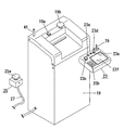
図1及び図2において、産業ロボットとしての成形品取出機1は、樹脂成形機3の固定プラテン5上に取付けられた本体フレーム7上を、樹脂成形機3の中心軸線直交方向へ往復移動する走行体9、該走行体9にて樹脂成形機3の中心軸線方向へ延出する前後フレーム11上を往復移動する前後走行体13、該前後走行体13に取付けられた昇降ユニット15の下部に取付けられ、樹脂成形機3の金型間に進入して成形品を保持するチャック17とから構成される。尚、樹脂成形機3は、従来公知の射出成形機であり、その詳細な説明を省略する。
The present invention will be described below with reference to the drawings showing embodiments.
1 and 2, a molded product take-out machine 1 as an industrial robot reciprocates in a direction orthogonal to the central axis of the
該チャック17は樹脂成形機3の操作側又は反操作側の床面に設置された主制御ボックス19内に収容された主制御手段を構成する主制御装置21により樹脂成形機3の中心軸線方向及び中心軸線直交方向と上下方向の三次元方向へそれぞれ移動制御され、樹脂成形機3により成形された成形品を樹脂成形機3の操作側又は反操作側に設定された解放位置に取出す。
The
主制御ボックス19の盤面上には主電源スイッチ19aの他に非常停止釦19b等が設けられている。また、主制御ボックス19の盤面上には可搬形操作手段を構成する可搬形操作ボックス23が着脱可能に取付けられている。更に、主制御ボックス19には非常停止釦25aが設けられた非常停止手段を構成する可搬形の非常停止ユニット25が、電気ケーブル27により電気的に接続されている。尚、主制御ボックス19の設置箇所としては、成形品取出機1の本体フレーム7、走行体9であってもよい。
On the panel surface of the
非常停止ユニット25は樹脂成形機3や成形品取出機1に対し、例えば永久磁石やフック等により仮固定できるように構成される。主制御装置21と非常停止ユニット25を接続する電気ケーブル27は、可搬形操作ボックス23を使用してチャック17の移動位置、移動速度、移動時間等の各種取出しデータを、チャック17の移動状態を実際に確認しながら設定入力する教示入力の際に、作業者がチャック17の移動状態を直接確認できる位置へ延びる適宜の長さからなる。
The
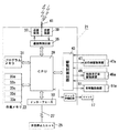
図3に示すように、上記した主制御装置21のCPU29にはプログラムメモリ31及び作業メモリ33が接続され、プログラムメモリ31には成形品の取出し動作プログラムデータや、設定された、または設定される取出しデータを送受信するための通信プログラムデータ及び非常停止動作を実行する非常停止プログラムデータ等の各種プログラムデータが記憶される。
As shown in FIG. 3, a
また、作業メモリ33には設定されたチャック17の移動位置、移動速度等の動作データを記憶する動作データ領域33a、チャック17の現在位置に関する位置データを記憶する位置データ領域33b、上記した可搬形操作ボックス23から送信された各種設定データを一時的に記憶する受信データバッファ領域33c、可搬形操作ボックス23に送信する動作データを一時的に記憶する送信データバッファ領域33d及び非常停止フラグ33e等から構成される。
In the work memory 33, an
CPU29には通信制御回路35が接続され、該通信制御回路35には、電磁波や、例えば赤外線等の光等の無線通信媒体の送信装置37及び受信装置39が接続されている。通信制御回路35は動作データ領域33a及び位置データ領域33bから転送されて送信データバッファ領域33dに記憶された各種データを送信装置37のアンテナ41を介して可搬形操作ボックス23へ送信する。また、通信制御回路35はアンテナ41を介して受信装置39が受信した可搬形操作ボックス23からの各種データを受信データバッファ領域33cへ転送して記憶させる。
A
CPU29には駆動制御回路43が接続され、該駆動制御回路43は接続された走行体駆動装置47、前後走行体駆動装置49及び昇降駆動装置51等をそれぞれ駆動制御してチャック17を所定の位置へ移動するように制御すると共にチャック17による成形品の保持制御を行う。
A
この駆動制御回路43は各駆動装置47,49,51に設けられた、例えばロータリーエンコーダ等の位置検出器47a,49a,51aからの位置検出信号及び動作データ領域33aに記憶された各種動作データに基づいて走行体駆動装置47、前後走行体駆動装置49及び昇降駆動装置51を閉ループ制御してチャック17を所望の位置へ移動するように制御する。CPU29は位置検出器47a,49a,51aからの位置検出信号に基づいてチャック17の現在位置を位置データとして位置データ領域33bに記憶させる。
This
CPU29には、上記した非常停止ユニット25がインターフェース53を介して接続され、非常停止釦25aの操作により非常停止ユニット25から非常停止指示信号が入力されたとき、非常停止フラグ33eをセットしてチャック17の移動を非常停止するように割込み制御する。
When the
図4に示すように、可搬形操作ボックス23にはチャック17の動作データを設定する際に手動設定モード、教示設定モード等に切換えるモード切換えスイッチ23a、チャック17の動作データを入力するための入力キー23b、移動指示釦23c、データ要求釦23d、登録釦23e及び切換えられた設定モードや入力された各種データ、チャック17の現在位置、移動方向等を表示するLCD等の表示部材23fが設けられている。
As shown in FIG. 4, in the
表示部材23fは、例えば上記した各スイッチやキー及び釦23a、23b、23c、23d、23eを表示し、表示されたこれらの画像がタッチ操作された際に、所定のデータや指示信号を入力する、所謂タッチパネル構造としてもよい。
The
可搬形操作ボックス23内には副制御装置55が内蔵されている。該副制御装置55のCPU57にはプログラムメモリ59及び作業メモリ61が接続され、プログラムメモリ59には動作データを入力する際のデータ設定プログラムデータ、即ち、チャック17の移動位置及び移動速度等を直接数値入力して設定する手動入力モード、チャック17を所定の位置へ実際に移動して動作データを入力する教示入力モード等を実行するためのデータ設定プログラムデータや主制御装置21との間にて設定されたチャック17の動作データやチャック17の位置データを送受信するための通信プログラムデータ、非常停止ユニット25との距離に応じて可搬形操作ボックス23によるデータ設定を可能化したり、禁止する設定許可プログラムデータ等の各種プログラムデータが記憶される。
A
また、作業メモリ61には主制御装置21の動作データ領域33aから転送されたチャック17の動作データを記憶する動作データ領域61a、位置データ領域33bから転送されたチャック17の位置データを記憶する位置データ領域61b、手動設定されるチャック17の動作データを一時的に記憶するバッファ領域61c及び可搬形操作ボックス23による動作データの設定入力の許可状態を判定する許可フラグ61d等から構成される。
The work memory 61 stores an
CPU57には設定制御回路63が接続され、該設定制御回路63は接続されたモード切換スイッチ23a、入力キー23b、移動指示釦23c、データ要求釦23d、登録釦23eの操作状態を検出して所定の指示信号を出力する。また、CPU57には表示制御回路65が接続され、表示制御回路65は接続された表示部材23fに設定モード状態、動作データ領域33aから転送されたチャック17の動作データや、位置データ領域33bから転送された位置データ及び手動設定時には設定された動作データを表示させる。
A setting
CPU57には可搬形操作ボックス23と非常停止ユニット25との距離(間隔)を検出する距離判別手段としての距離検出回路67がインターフェース69を介して接続され、該距離検出回路67は接続された受信部材71が受信した信号の強度に基づいて可搬形操作ボックス23と非常停止ユニット25の距離(間隔)が所定以下の場合には可搬形操作ボックス23による設定入力を可能にする許可信号を、反対に所定以上の場合には禁止信号を出力する。
The
更に、CPU57には通信制御回路73が接続され、該通信制御回路73には、電磁波や、例えば赤外線等の光等の無線通信媒体の送信装置75及び受信装置77が接続されている。通信制御回路73は手動設定時にはバッファ領域61cから転送されるチャック17の動作データを、教示設定入力時にはチャック17の移動指示信号を送信装置75のアンテナ79を介して主制御装置21へ送信する。また、通信制御回路73はアンテナ79を介して受信装置77が受信した主制御装置21からの各種データを動作データ領域61a、位置データ領域61bへ転送して記憶させる。
Further, a
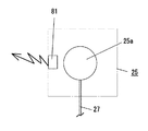
図5に示すように、非常停止ユニット25は非常停止釦25aが操作された際に、電気ケーブル27を介して主制御装置21に非常停止信号を出力する。また、非常停止ユニット25には距離信号出力手段としての常時送信部材81が設けられ、該常時送信部材81は常に一定強度の信号を可搬形操作ボックス23に向って出力する。
As shown in FIG. 5, the
常時送信部材81としては送信媒体として一定強度の電波や、例えば赤外線等の光を常時出力するように構成される。常時送信部材81から出力される送信媒体を光とする場合には、無指向化する必要から全方位に対する光の照射を可能にするため、複数個の発光部材で構成してもよい。
The
次に、可搬形操作ボックス23を使用した動作データを教示入力する際の作用及び非常停止作用を説明する。尚、可搬形操作ボックス23により動作データを手動入力して設定する際の作用については、その詳細な説明を省略する。
Next, an operation and an emergency stop operation when teaching and inputting operation data using the
可搬形操作ボックス23により成形品取出機1のチャック17を所望の位置へ実際に移動してチャック17の移動に関する各種データを教示設定入力するのは、作業者は先ず、主制御装置21から取外した可搬形操作ボックス23のモード切換スイッチ23aを切換え操作したり、又は表示部材23fに表示されたモード切換スイッチ23aをタッチ操作して設定モードを教示入力モードに切換え、この状態で可搬形操作ボックス23を携帯してチャック17の移動状態を直接確認できる箇所へ移動して行う。また、教示設定作業に先立って、作業者はデータ要求釦23dを操作して主制御装置21へ動作データ領域33aに記憶されたチャック17の動作データや位置データ領域33bに記憶されたチャック17の位置データを可搬形操作ボックス23へ送信するように指示する。
The operator first removes the
主制御装置21はデータ要求信号に基づいて動作データ領域33a及び位置データ領域33bから転送されて送信バッファ領域33dに記憶された動作データや位置データを送信装置37から可搬形操作ボックス23へ送信すると、可搬形操作ボックス23は受信した動作データや位置データを動作データ領域61a、位置データ領域61bにそれぞれ記憶させた後にこれらのデータを表示制御回路65に出力して表示部材23fに表示させる。
When
作業者は、表示部材23fに表示されたチャック17の動作データ及び位置データを参照しながら、チャック17を所望の方向へ移動させるための移動指示釦23cを操作すると、CPU57は移動指示釦23cにより指定されたチャック17の駆動指示データを、送信部材75を介して主制御装置21へ出力する。主制御装置21は受信した駆動指示信号を駆動制御回路43に出力し、駆動指示信号により指示された駆動装置47,49,51を選択的に駆動してチャック17を所定の方向へ移動させる。
When the operator operates the
尚、上記駆動指示信号に基づいてチャック17が移動すると、CPU29は対応する位置検出器47a、49a、51aからの位置検出信号に基づいて位置データ領域33bに記憶されたチャック17の位置データを移動した位置の位置データに書換えた後、書換えられた位置データを可搬形操作ボックス23へ送信する。これにより可搬形操作ボックス23の表示部材23fには、チャック17の実際の移動位置に関する位置データが常に表示される。
When the
作業者は、携帯した可搬形操作ボックス23と主制御装置21との間で各種データ、信号等を送受信しながらチャック17を、所望の位置へ実際に移動させた後に、チャック17の移動状態を目視で直接確認する作業を行い、チャック17の移動位置が確認されると、登録釦23eを操作し、主制御装置21へ登録指示信号を送信させる。これにより主制御装置21は動作データ領域33aに記憶された動作データを、位置データ領域33bに記憶されたチャック17の現在位置データに書換えてチャック17の動作データを設定登録させる。
The operator actually moves the
上記した作業の繰返しによりチャック17を実際に所望の各位置へ移動し、その移動状態を確認しながらチャック17の動作データを設定する。
尚、作業者は、表示部材23fにチャック17の実際の位置データと共に前回に設定されたチャック17の動作データがそれぞれ表示されているため、以前の設定状態と、新たに教示入力されたチャック17の設定データとを比較することができる。
By repeating the above operation, the
In addition, since the operation data of the
上記したチャック17の動作データの教示入力時においては、可搬形操作ボックス23を携帯した作業者は、非常停止ユニット25を、可搬形操作ボックス23を操作しながら非常停止釦25aを操作可能な近くの場所に配置しておく必要がある。この非常停止ユニット25は常時送信部材81から可搬形操作ボックス23に向って一定の信号強度で電波又は光を常時出力している。一方、可搬形操作ボックス23の受信部材71は常時送信部材81からの信号を受信し、その距離検出回路67により受信した常時送信部材81からの信号強度に基づいて可搬形操作ボックス23と非常停止ユニット25の距離(間隔)を検出している。
At the time of teaching input of the operation data of the
図6において、ステップ91において距離検出回路67により常時送信部材81から受診した信号の強度が一定レベル以上か否かを判別し、可搬形操作ボックス23と非常停止ユニット25との距離が、作業者が緊急時に非常停止スイッチ25aを押下操作可能な範囲内の距離でステップ91がYESのとき、ステップ93により許可フラグ61dをセットした後、ステップ95により可搬形操作ボックス23による上記したチャック17の動作データの教示入力を可能化処理してステップ91に戻る。
In FIG. 6, it is determined whether or not the strength of the signal constantly received from the
一方、常時送信部材81からの信号強度が一定レベル以下で、上記ステップ91がNOのとき、可搬形操作ボックス23と非常停止ユニット25との距離が、作業者が緊急時に非常停止スイッチ25aを押下操作できない距離に離れていると判断し、ステップ97において許可フラグ61dをリセットした後、ステップ99により可搬形操作ボックス23による上記したチャック17の動作データの教示入力を不可能化処理してステップ91に戻る。
On the other hand, when the signal intensity from the
これにより作業者は、図7に示すように非常停止ユニット25が可搬形操作ボックス23から、直ちに非常停止スイッチ25aを操作できる範囲内に配置されている場合にのみ、可搬形操作ボックス23による教示入力を可能にさせる一方、可搬形操作ボックス23による教示入力を不可能化することにより、可搬形操作ボックス23、即ち作業者と非常停止ユニット25が、非常停止スイッチ25aを直ちに押下操作できない距離に離れていることを気付かせることができる。
As a result, the operator teaches by the
そして動作データの教示入力時に成形品取出機1が異常動作した際には、作業者は手の届く範囲に配置された非常停止ユニット25の非常停止スイッチ25aを操作すると、主制御装置21は非常停止信号により非常停止フラグ33eをセットしてチャック17を非常停止させるように割込み処理を実行し、作業者の安全性を確保する。
When the molded article take-out machine 1 operates abnormally when the operation data is input, when the operator operates the
上記説明は、可搬形操作ボックス23と非常停止ユニット25が、可搬形操作ボックス23を携帯した作業者が、非常停止スイッチ25aを直ちに押下操作できない距離以上に離れている場合に、可搬形操作ボックス23による教示入力を不可能化することにより非常停止ユニット25が作業者の身近にないことを気付かせる構成としたが、可搬形操作ボックス23と非常停止ユニット25の距離が上記した所定の距離以上、離れた場合に、上記した可搬形操作ボックス23による教示入力を禁止すると共に警報ランプや警報ブザー等の警報手段を作動して作業者に、非常停止ユニット25が非常停止スイッチ25aを直ちに押下操作できる範囲にないことを報知する構成としてもよい。
The above description is based on the description that the
また、上記説明は、産業ロボットとして成形品取出機1を例に説明したが、本発明の産業ロボットはこれに限定されるものではなく、例えば組立てロボット、塗装ロボット、加工ロボット、溶接ロボット等の各種産業ロボットにおいても適用できる。 Moreover, although the said description demonstrated the molded product extraction machine 1 as an example as an industrial robot, the industrial robot of this invention is not limited to this, For example, an assembly robot, a painting robot, a processing robot, a welding robot, etc. It can also be applied to various industrial robots.
1 産業ロボットとしての成形品取出し機
21 主制御手段としての主制御回路
23 可搬形操作手段としての可搬形操作ボックス
25 非常停止手段としての非常停止ユニット
25a 非常停止釦
67 距離判別手段としての距離検出回路
81 距離信号出力手段としての常時送信部材
DESCRIPTION OF SYMBOLS 1 Mold take-out
Claims (9)
主制御手段に対して電気ケーブルを介して電気的に接続されると共に非常停止釦が設けられた非常停止手段には可搬形設定手段との距離を判別するための距離信号を常時出力する距離信号出力手段を備えると共に可搬形設定手段には非常停止手段からの距離信号に基づいて両者間の距離を判別する距離判別手段を設け、
非常停止手段と可搬形設定手段の距離が非常停止釦の操作可能距離内の場合には可搬形設定ユニットによる各種データ設定を可能化する一方、該距離が非常停止釦の操作不能距離内の場合には可搬形設定ユニットによる各種データ設定を不可能化する産業ロボットの制御装置。 Main control means for controlling the industrial robot to perform a predetermined operation based on the operation data, and emergency stop means connected to the main control means by an electric cable having a length corresponding to the work range and provided with an emergency stop button; in the control device for setting various operation data of various data to the main control means is transmitted and received in the wireless communication medium between the remote operable portable setting means to the main control unit,
A distance signal that is electrically connected to the main control means via an electric cable and that constantly outputs a distance signal for determining the distance from the portable setting means to the emergency stop means provided with an emergency stop button In addition to the output means, the portable setting means is provided with distance determining means for determining the distance between the two based on the distance signal from the emergency stop means,
When the distance between the emergency stop means and the portable setting means is within the operable distance of the emergency stop button, various data settings can be made by the portable setting unit, while the distance is within the inoperable distance of the emergency stop button. Is an industrial robot controller that makes it impossible to set various data using a portable setting unit.
主制御手段に対して作業範囲に応じた長さの電気ケーブルを介して接続され、非常停止釦が設けられた非常停止手段から出力される距離信号に基づいて可搬形設定手段との距離が非常停止釦の操作可能距離内の場合には可搬形設定ユニットによる各種データ設定を可能化する一方、該距離が非常停止釦の操作不能距離以上の場合には可搬形設定ユニットによる各種データ設定を不可能化する産業ロボットの制御方法。 Various data is transmitted / received via a wireless communication medium between the main control unit of the industrial robot for causing the hand unit to perform a predetermined operation based on the operation data and the portable setting unit for setting and inputting the operation data, thereby setting desired operation data. When
It is connected to the main control means via an electric cable having a length corresponding to the work range, and the distance from the portable setting means is emergency based on the distance signal output from the emergency stop means provided with the emergency stop button. When the stop button is within the operable distance, various data settings can be made by the portable setting unit. On the other hand, when the distance is longer than the inoperable distance of the emergency stop button, various data settings by the portable setting unit are not allowed. An industrial robot control method to be made possible.
Priority Applications (1)
| Application Number | Priority Date | Filing Date | Title |
|---|---|---|---|
| JP2005031595A JP4353426B2 (en) | 2005-02-08 | 2005-02-08 | Industrial robot control device and control method |
Applications Claiming Priority (1)
| Application Number | Priority Date | Filing Date | Title |
|---|---|---|---|
| JP2005031595A JP4353426B2 (en) | 2005-02-08 | 2005-02-08 | Industrial robot control device and control method |
Publications (3)
| Publication Number | Publication Date |
|---|---|
| JP2006218548A JP2006218548A (en) | 2006-08-24 |
| JP2006218548A5 JP2006218548A5 (en) | 2008-02-28 |
| JP4353426B2 true JP4353426B2 (en) | 2009-10-28 |
Family
ID=36981197
Family Applications (1)
| Application Number | Title | Priority Date | Filing Date |
|---|---|---|---|
| JP2005031595A Active JP4353426B2 (en) | 2005-02-08 | 2005-02-08 | Industrial robot control device and control method |
Country Status (1)
| Country | Link |
|---|---|
| JP (1) | JP4353426B2 (en) |
Cited By (2)
| Publication number | Priority date | Publication date | Assignee | Title |
|---|---|---|---|---|
| JP2018101945A (en) * | 2016-12-21 | 2018-06-28 | 三菱重工機械システム株式会社 | Wireless operation system and carton forming machine using the same |
| US10661989B2 (en) | 2015-05-11 | 2020-05-26 | Murata Machinery, Ltd. | Automated equipment system, emergency stop terminal, and operation terminal control method |
Families Citing this family (11)
| Publication number | Priority date | Publication date | Assignee | Title |
|---|---|---|---|---|
| DE112007000394T5 (en) * | 2006-02-14 | 2008-12-24 | Kabushiki Kaisha Yaskawa Denki, Kitakyushu | robot system |
| JP2009301271A (en) * | 2008-06-12 | 2009-12-24 | Idec Corp | Safety control method and safety control system |
| JP2010058216A (en) * | 2008-09-03 | 2010-03-18 | Ihi Corp | Remote control device |
| ES2868248T3 (en) * | 2012-10-10 | 2021-10-21 | Citizen Watch Co Ltd | Portable type operating instruction input device and device provided with portable type operating instruction input device |
| WO2015119264A1 (en) * | 2014-02-06 | 2015-08-13 | ヤンマー株式会社 | Remote operation device for parallel travel work system |
| WO2015119265A1 (en) * | 2014-02-06 | 2015-08-13 | ヤンマー株式会社 | Travel control system |
| KR102107556B1 (en) | 2014-02-06 | 2020-05-07 | 얀마 가부시키가이샤 | Parallel travel work system |
| CN105980948B (en) | 2014-02-06 | 2019-12-31 | 洋马株式会社 | Method for setting travel route of autonomous travel work vehicle |
| WO2015118730A1 (en) * | 2014-02-06 | 2015-08-13 | ヤンマー株式会社 | Remote operation device for parallel travel work system |
| WO2015173856A1 (en) * | 2014-05-12 | 2015-11-19 | 富士機械製造株式会社 | Portable panel device and operation system |
| JP5816723B1 (en) * | 2014-07-10 | 2015-11-18 | Dmg森精機株式会社 | Mechanical device and control method thereof, remote control device and main control device |
Family Cites Families (6)
| Publication number | Priority date | Publication date | Assignee | Title |
|---|---|---|---|---|
| JPS61164794A (en) * | 1985-01-09 | 1986-07-25 | 三菱電機株式会社 | Industrial robot |
| JPH07195285A (en) * | 1993-12-29 | 1995-08-01 | Bridgestone Corp | Robot controller |
| JPH08206988A (en) * | 1995-02-06 | 1996-08-13 | Yaskawa Electric Corp | Emergency stop device of robot |
| JP3901772B2 (en) * | 1996-11-13 | 2007-04-04 | 三菱重工業株式会社 | Robot teaching operation method |
| JP2003200371A (en) * | 2001-12-28 | 2003-07-15 | Kawasaki Heavy Ind Ltd | Robot system and method of operating it |
| JP2004355195A (en) * | 2003-05-28 | 2004-12-16 | Yaskawa Electric Corp | Teaching operation device for robot |
-
2005
- 2005-02-08 JP JP2005031595A patent/JP4353426B2/en active Active
Cited By (2)
| Publication number | Priority date | Publication date | Assignee | Title |
|---|---|---|---|---|
| US10661989B2 (en) | 2015-05-11 | 2020-05-26 | Murata Machinery, Ltd. | Automated equipment system, emergency stop terminal, and operation terminal control method |
| JP2018101945A (en) * | 2016-12-21 | 2018-06-28 | 三菱重工機械システム株式会社 | Wireless operation system and carton forming machine using the same |
Also Published As
| Publication number | Publication date |
|---|---|
| JP2006218548A (en) | 2006-08-24 |
Similar Documents
| Publication | Publication Date | Title |
|---|---|---|
| JP4353426B2 (en) | Industrial robot control device and control method | |
| TWI611883B (en) | Industrial remote operating robot system | |
| CN107817769B (en) | Robot system having teaching operation panel communicating with robot control unit | |
| JP4596376B2 (en) | Automatic machine system and communication control method thereof | |
| US7577497B2 (en) | Industrial robot with portable emergency stop unit | |
| US8401678B2 (en) | Mobile control and monitoring system | |
| US9782921B2 (en) | Injection molding system with additional injection device | |
| JP6338617B2 (en) | Teaching device | |
| JP5394136B2 (en) | Wireless teaching operation panel and robot control system | |
| WO2016006423A1 (en) | Mechanical apparatus, method for controlling same, remote operating apparatus, and main operating apparatus | |
| JP2009301271A (en) | Safety control method and safety control system | |
| CN107963127A (en) | The device of the operation sequence of auxiliary maneuvering vehicle | |
| US11254000B2 (en) | Machine teaching terminal, machine, non-transitory computer readable medium storing a program, and safety confirmation method for teaching machine | |
| JP3732452B2 (en) | Control device | |
| JP5364287B2 (en) | Mold take-out machine | |
| JP2016097467A (en) | Robot system and control method of robot system | |
| KR101602930B1 (en) | A controll apparatus for hoist | |
| US20200338740A1 (en) | Control Method By Robot System And Robot System | |
| JP5307491B2 (en) | Teaching pendant | |
| JP2009241541A5 (en) | ||
| CN113924191B (en) | Method and system for automatically protecting the operation of a robotic system controlled by a mobile manipulator | |
| JP6260634B2 (en) | Valve opening / closing system, valve control device | |
| KR102061053B1 (en) | System and method for alarming loading between excavator and truck | |
| EP1906284A1 (en) | A control device for controlling an industrial robot | |
| JP7209188B2 (en) | Communication method, communication system, transmitter and receiver |
Legal Events
| Date | Code | Title | Description |
|---|---|---|---|
| A521 | Request for written amendment filed |
Free format text: JAPANESE INTERMEDIATE CODE: A523 Effective date: 20080116 |
|
| A621 | Written request for application examination |
Free format text: JAPANESE INTERMEDIATE CODE: A621 Effective date: 20080116 |
|
| A131 | Notification of reasons for refusal |
Free format text: JAPANESE INTERMEDIATE CODE: A131 Effective date: 20090625 |
|
| A521 | Request for written amendment filed |
Free format text: JAPANESE INTERMEDIATE CODE: A523 Effective date: 20090629 |
|
| A977 | Report on retrieval |
Free format text: JAPANESE INTERMEDIATE CODE: A971007 Effective date: 20090630 |
|
| TRDD | Decision of grant or rejection written | ||
| A01 | Written decision to grant a patent or to grant a registration (utility model) |
Free format text: JAPANESE INTERMEDIATE CODE: A01 Effective date: 20090723 |
|
| A01 | Written decision to grant a patent or to grant a registration (utility model) |
Free format text: JAPANESE INTERMEDIATE CODE: A01 |
|
| A61 | First payment of annual fees (during grant procedure) |
Free format text: JAPANESE INTERMEDIATE CODE: A61 Effective date: 20090723 |
|
| R150 | Certificate of patent or registration of utility model |
Ref document number: 4353426 Country of ref document: JP Free format text: JAPANESE INTERMEDIATE CODE: R150 Free format text: JAPANESE INTERMEDIATE CODE: R150 |
|
| FPAY | Renewal fee payment (event date is renewal date of database) |
Free format text: PAYMENT UNTIL: 20120807 Year of fee payment: 3 |
|
| FPAY | Renewal fee payment (event date is renewal date of database) |
Free format text: PAYMENT UNTIL: 20130807 Year of fee payment: 4 |
|
| R250 | Receipt of annual fees |
Free format text: JAPANESE INTERMEDIATE CODE: R250 |
|
| R250 | Receipt of annual fees |
Free format text: JAPANESE INTERMEDIATE CODE: R250 |
|
| R250 | Receipt of annual fees |
Free format text: JAPANESE INTERMEDIATE CODE: R250 |
|
| R250 | Receipt of annual fees |
Free format text: JAPANESE INTERMEDIATE CODE: R250 |
|
| R250 | Receipt of annual fees |
Free format text: JAPANESE INTERMEDIATE CODE: R250 |
|
| R250 | Receipt of annual fees |
Free format text: JAPANESE INTERMEDIATE CODE: R250 |
|
| R250 | Receipt of annual fees |
Free format text: JAPANESE INTERMEDIATE CODE: R250 |
|
| R250 | Receipt of annual fees |
Free format text: JAPANESE INTERMEDIATE CODE: R250 |
|
| R250 | Receipt of annual fees |
Free format text: JAPANESE INTERMEDIATE CODE: R250 |
|
| R250 | Receipt of annual fees |
Free format text: JAPANESE INTERMEDIATE CODE: R250 |
|
| R250 | Receipt of annual fees |
Free format text: JAPANESE INTERMEDIATE CODE: R250 |
|
| R250 | Receipt of annual fees |
Free format text: JAPANESE INTERMEDIATE CODE: R250 |