JP4353261B2 - Liquid discharge head - Google Patents
Liquid discharge head Download PDFInfo
- Publication number
- JP4353261B2 JP4353261B2 JP2007043919A JP2007043919A JP4353261B2 JP 4353261 B2 JP4353261 B2 JP 4353261B2 JP 2007043919 A JP2007043919 A JP 2007043919A JP 2007043919 A JP2007043919 A JP 2007043919A JP 4353261 B2 JP4353261 B2 JP 4353261B2
- Authority
- JP
- Japan
- Prior art keywords
- actuator unit
- piezoelectric actuator
- groove
- unit
- flow path
- Prior art date
- Legal status (The legal status is an assumption and is not a legal conclusion. Google has not performed a legal analysis and makes no representation as to the accuracy of the status listed.)
- Active
Links
Images


Classifications
-
- B—PERFORMING OPERATIONS; TRANSPORTING
- B41—PRINTING; LINING MACHINES; TYPEWRITERS; STAMPS
- B41J—TYPEWRITERS; SELECTIVE PRINTING MECHANISMS, i.e. MECHANISMS PRINTING OTHERWISE THAN FROM A FORME; CORRECTION OF TYPOGRAPHICAL ERRORS
- B41J2/00—Typewriters or selective printing mechanisms characterised by the printing or marking process for which they are designed
- B41J2/005—Typewriters or selective printing mechanisms characterised by the printing or marking process for which they are designed characterised by bringing liquid or particles selectively into contact with a printing material
- B41J2/01—Ink jet
- B41J2/135—Nozzles
- B41J2/14—Structure thereof only for on-demand ink jet heads
- B41J2/14201—Structure of print heads with piezoelectric elements
- B41J2/14209—Structure of print heads with piezoelectric elements of finger type, chamber walls consisting integrally of piezoelectric material
- B41J2002/14217—Multi layer finger type piezoelectric element
-
- B—PERFORMING OPERATIONS; TRANSPORTING
- B41—PRINTING; LINING MACHINES; TYPEWRITERS; STAMPS
- B41J—TYPEWRITERS; SELECTIVE PRINTING MECHANISMS, i.e. MECHANISMS PRINTING OTHERWISE THAN FROM A FORME; CORRECTION OF TYPOGRAPHICAL ERRORS
- B41J2/00—Typewriters or selective printing mechanisms characterised by the printing or marking process for which they are designed
- B41J2/005—Typewriters or selective printing mechanisms characterised by the printing or marking process for which they are designed characterised by bringing liquid or particles selectively into contact with a printing material
- B41J2/01—Ink jet
- B41J2/135—Nozzles
- B41J2/14—Structure thereof only for on-demand ink jet heads
- B41J2/14201—Structure of print heads with piezoelectric elements
- B41J2/14209—Structure of print heads with piezoelectric elements of finger type, chamber walls consisting integrally of piezoelectric material
- B41J2002/14225—Finger type piezoelectric element on only one side of the chamber
-
- B—PERFORMING OPERATIONS; TRANSPORTING
- B41—PRINTING; LINING MACHINES; TYPEWRITERS; STAMPS
- B41J—TYPEWRITERS; SELECTIVE PRINTING MECHANISMS, i.e. MECHANISMS PRINTING OTHERWISE THAN FROM A FORME; CORRECTION OF TYPOGRAPHICAL ERRORS
- B41J2/00—Typewriters or selective printing mechanisms characterised by the printing or marking process for which they are designed
- B41J2/005—Typewriters or selective printing mechanisms characterised by the printing or marking process for which they are designed characterised by bringing liquid or particles selectively into contact with a printing material
- B41J2/01—Ink jet
- B41J2/135—Nozzles
- B41J2/14—Structure thereof only for on-demand ink jet heads
- B41J2/14201—Structure of print heads with piezoelectric elements
- B41J2002/14306—Flow passage between manifold and chamber
-
- B—PERFORMING OPERATIONS; TRANSPORTING
- B41—PRINTING; LINING MACHINES; TYPEWRITERS; STAMPS
- B41J—TYPEWRITERS; SELECTIVE PRINTING MECHANISMS, i.e. MECHANISMS PRINTING OTHERWISE THAN FROM A FORME; CORRECTION OF TYPOGRAPHICAL ERRORS
- B41J2/00—Typewriters or selective printing mechanisms characterised by the printing or marking process for which they are designed
- B41J2/005—Typewriters or selective printing mechanisms characterised by the printing or marking process for which they are designed characterised by bringing liquid or particles selectively into contact with a printing material
- B41J2/01—Ink jet
- B41J2/135—Nozzles
- B41J2/14—Structure thereof only for on-demand ink jet heads
- B41J2002/14362—Assembling elements of heads
-
- B—PERFORMING OPERATIONS; TRANSPORTING
- B41—PRINTING; LINING MACHINES; TYPEWRITERS; STAMPS
- B41J—TYPEWRITERS; SELECTIVE PRINTING MECHANISMS, i.e. MECHANISMS PRINTING OTHERWISE THAN FROM A FORME; CORRECTION OF TYPOGRAPHICAL ERRORS
- B41J2/00—Typewriters or selective printing mechanisms characterised by the printing or marking process for which they are designed
- B41J2/005—Typewriters or selective printing mechanisms characterised by the printing or marking process for which they are designed characterised by bringing liquid or particles selectively into contact with a printing material
- B41J2/01—Ink jet
- B41J2/135—Nozzles
- B41J2/14—Structure thereof only for on-demand ink jet heads
- B41J2002/14459—Matrix arrangement of the pressure chambers
-
- B—PERFORMING OPERATIONS; TRANSPORTING
- B41—PRINTING; LINING MACHINES; TYPEWRITERS; STAMPS
- B41J—TYPEWRITERS; SELECTIVE PRINTING MECHANISMS, i.e. MECHANISMS PRINTING OTHERWISE THAN FROM A FORME; CORRECTION OF TYPOGRAPHICAL ERRORS
- B41J2/00—Typewriters or selective printing mechanisms characterised by the printing or marking process for which they are designed
- B41J2/005—Typewriters or selective printing mechanisms characterised by the printing or marking process for which they are designed characterised by bringing liquid or particles selectively into contact with a printing material
- B41J2/01—Ink jet
- B41J2/135—Nozzles
- B41J2/14—Structure thereof only for on-demand ink jet heads
- B41J2002/14491—Electrical connection
-
- B—PERFORMING OPERATIONS; TRANSPORTING
- B41—PRINTING; LINING MACHINES; TYPEWRITERS; STAMPS
- B41J—TYPEWRITERS; SELECTIVE PRINTING MECHANISMS, i.e. MECHANISMS PRINTING OTHERWISE THAN FROM A FORME; CORRECTION OF TYPOGRAPHICAL ERRORS
- B41J2202/00—Embodiments of or processes related to ink-jet or thermal heads
- B41J2202/01—Embodiments of or processes related to ink-jet heads
- B41J2202/20—Modules
Landscapes
- Particle Formation And Scattering Control In Inkjet Printers (AREA)
Description
本発明は、液体吐出ヘッドに関し、特に流路ユニットとアクチュエータユニットとが接着剤を介して接合された液体吐出ヘッドに関する。 The present invention relates to a liquid discharge head, and more particularly to a liquid discharge head in which a flow path unit and an actuator unit are bonded via an adhesive.
特許文献1に記載されたインクジェットヘッドは、圧力室が開口した流路ユニットであるキャビティプレートの一方の平面上に、圧電アクチュエータ(圧電アクチュエータユニット)が積層されたものである。圧電アクチュエータの側面には、その上面に形成された駆動電極を外部配線と電気的に接続するために用いられる側面電極が形成されている。そのため、側面電極が金属製のキャビティプレートとショートする可能性が高くなる。そこで、特許文献1のインクジェットヘッドでは、キャビティプレートの上面に凹部を形成し、側面電極とキャビティプレートとを凹部を介して隔てることによって、側面電極とキャビティプレートとの電気的なショートを防止している。 The ink jet head described in Patent Document 1 is obtained by laminating a piezoelectric actuator (piezoelectric actuator unit) on one plane of a cavity plate that is a flow path unit having an open pressure chamber. Side electrodes used for electrically connecting a drive electrode formed on the upper surface of the piezoelectric actuator to external wiring are formed on the side surface of the piezoelectric actuator. Therefore, the possibility that the side electrode is short-circuited with the metal cavity plate is increased. Therefore, in the ink jet head of Patent Document 1, a recess is formed on the upper surface of the cavity plate, and the side electrode and the cavity plate are separated by the recess, thereby preventing an electrical short circuit between the side electrode and the cavity plate. Yes.
特許文献1に記載されたインクジェットヘッドを製造する際、通常は、キャビティプレートの上面に接着剤を塗布した後に、圧電アクチュエータをキャビティプレートの上面に対して押圧する。その際、キャビティプレートの上面に形成された凹部は、接着剤の逃がし溝としても機能する。すなわち、キャビティプレートと圧電アクチュエータとの間からはみ出した接着剤が、凹部内に収容される。そのため、接着剤が圧電アクチュエータの側面をせり上がって、圧電アクチュエータの上面に接着剤が付着することによって生じる吐出不良を防止することができる。 When manufacturing the ink jet head described in Patent Document 1, usually, an adhesive is applied to the upper surface of the cavity plate, and then the piezoelectric actuator is pressed against the upper surface of the cavity plate. At that time, the recess formed on the upper surface of the cavity plate also functions as an adhesive relief groove. That is, the adhesive protruding from between the cavity plate and the piezoelectric actuator is accommodated in the recess. Therefore, it is possible to prevent ejection failure caused by the adhesive rising up the side surface of the piezoelectric actuator and adhering to the upper surface of the piezoelectric actuator.
しかしながら、特許文献1のインクジェットヘッドを製造するに当たって圧電アクチュエータをキャビティプレートの上面に対して押圧すると、圧電アクチュエータの外縁近傍領域にクラックが生じることがある。これは、凹部と対向している圧電アクチュエータの外縁近傍領域がキャビティプレートによって支持されていないために、外縁近傍領域に加えられた押圧力が圧電アクチュエータに剪断力として作用するからである。圧電アクチュエータにクラックが生じると、インクが吐出不良又は吐出不能となることがある。 However, when the piezoelectric actuator is pressed against the upper surface of the cavity plate in manufacturing the ink jet head of Patent Document 1, a crack may occur in a region near the outer edge of the piezoelectric actuator. This is because the area near the outer edge of the piezoelectric actuator facing the recess is not supported by the cavity plate, and the pressing force applied to the area near the outer edge acts as a shearing force on the piezoelectric actuator. If cracks occur in the piezoelectric actuator, ink may be ejected poorly or cannot be ejected.
本発明の目的は、流路ユニットに圧電アクチュエータユニットを接着剤を介して接合する際に、圧電アクチュエータユニットにクラックが生じにくい液体吐出ヘッドを提供することである。 An object of the present invention is to provide a liquid discharge head in which cracks are unlikely to occur in a piezoelectric actuator unit when the piezoelectric actuator unit is bonded to a flow path unit via an adhesive.
本発明の液体吐出ヘッドは、圧力室を含む複数の個別液体流路と、複数の前記圧力室の複数の開口が形成された表面とを有する流路ユニットと、前記複数の圧力室を覆うように前記流路ユニットの前記表面に接着剤を介して接合された圧電アクチュエータユニットとを備えている。そして、前記流路ユニットの前記表面には、前記複数の圧力室を取り囲む環状の溝が形成され、平面視で前記圧電アクチュエータユニットの外縁がその全周に亘って前記溝と対向している。さらに、前記溝内には、前記圧電アクチュエータユニットの外縁と対向しつつ前記圧電アクチュエータユニットの外縁を支える支持体が設けられている。そして、前記支持体は、前記溝の延在方向に沿った長さよりも前記溝の延在方向と直交する方向に沿った長さの方が長い。 The liquid discharge head of the present invention covers a plurality of individual liquid channels including pressure chambers, a channel unit having a surface on which a plurality of openings of the plurality of pressure chambers are formed, and the plurality of pressure chambers. And a piezoelectric actuator unit joined to the surface of the flow path unit via an adhesive. An annular groove surrounding the plurality of pressure chambers is formed on the surface of the flow path unit, and the outer edge of the piezoelectric actuator unit is opposed to the groove over the entire circumference in plan view . Furthermore, a support body that supports the outer edge of the piezoelectric actuator unit while being opposed to the outer edge of the piezoelectric actuator unit is provided in the groove. The length of the support along the direction orthogonal to the extending direction of the groove is longer than the length along the extending direction of the groove.
これにより、圧電アクチュエータユニットの外縁と対向する支持体が圧電アクチュエータユニットを支えるので、流路ユニットに圧電アクチュエータユニットを接着剤を介して接合する際に、圧電アクチュエータユニットに加えられた押圧力が、圧電アクチュエータユニットを介して支持体に加えられることになる。そのため、圧電アクチュエータユニットに作用する剪断力が大幅に小さくなって、圧電アクチュエータユニットにクラックが生じにくくなる。また、圧電アクチュエータユニットの外縁がその全周に亘って環状の溝と対向しているので、圧電アクチュエータユニットの全周にわたってその上面に接着剤が付着しにくくなる。さらに、圧電アクチュエータユニットの流路ユニットに対する位置ずれの許容誤差が大きくなる。 Thereby, since the support body which opposes the outer edge of the piezoelectric actuator unit supports the piezoelectric actuator unit, when the piezoelectric actuator unit is joined to the flow path unit via the adhesive, the pressing force applied to the piezoelectric actuator unit is It is added to the support via the piezoelectric actuator unit. For this reason, the shearing force acting on the piezoelectric actuator unit is significantly reduced, and cracks are less likely to occur in the piezoelectric actuator unit. In addition, since the outer edge of the piezoelectric actuator unit faces the annular groove over the entire circumference, the adhesive is less likely to adhere to the upper surface over the entire circumference of the piezoelectric actuator unit. Furthermore, the tolerance of displacement of the piezoelectric actuator unit with respect to the flow path unit increases.
このとき、前記支持体が、前記溝の側壁面から離隔した島状となるように設けられていることが好ましい。これにより、接合時に、流路ユニットの支持体以外の部分に塗布された接着剤が溝によって隔てられた支持体上に付着することがないので、圧電アクチュエータユニットの上面により一層接着剤が付着しにくくなる。 At this time, it is preferable that the support is provided so as to have an island shape separated from the side wall surface of the groove. Thereby, at the time of joining, the adhesive applied to the portion other than the support of the flow path unit does not adhere to the support separated by the groove, so that more adhesive adheres to the upper surface of the piezoelectric actuator unit. It becomes difficult.
別の観点において、本発明の液体吐出ヘッドは、圧力室を含む複数の個別液体流路と、複数の前記圧力室の複数の開口が形成された表面とを有する流路ユニットと、前記複数の圧力室を覆うように前記流路ユニットの前記表面に接着剤を介して接合された圧電アクチュエータユニットとを備えている。そして、前記流路ユニットの前記表面には、前記複数の圧力室を取り囲む一又は複数の溝が形成され、平面視で前記圧電アクチュエータユニットの外縁が、隣接する溝の間を除いてその全周に亘って前記溝と対向している。さらに、前記溝内には、前記圧電アクチュエータユニットの外縁と対向しつつ前記圧電アクチュエータユニットの外縁を支える支持体が前記溝の側壁面から離隔した島状となるように設けられている。そして、前記支持体は、前記溝の延在方向に沿った長さよりも前記溝の延在方向と直交する方向に沿った長さの方が長い。 In another aspect, the liquid ejection head of the present invention includes a plurality of individual liquid channels including pressure chambers, a channel unit having a surface on which a plurality of openings of the plurality of pressure chambers are formed, and the plurality of the plurality of pressure chambers. And a piezoelectric actuator unit joined to the surface of the flow path unit via an adhesive so as to cover the pressure chamber. One or a plurality of grooves surrounding the plurality of pressure chambers are formed on the surface of the flow path unit, and the outer edge of the piezoelectric actuator unit is seen in a plan view except for the entire circumference except between adjacent grooves. Across the groove. Furthermore, a support body that supports the outer edge of the piezoelectric actuator unit while facing the outer edge of the piezoelectric actuator unit is provided in the groove so as to have an island shape separated from the side wall surface of the groove. The length of the support along the direction orthogonal to the extending direction of the groove is longer than the length along the extending direction of the groove.
これにより、圧電アクチュエータユニットの外縁と対向する支持体が圧電アクチュエータユニットを支えるので、流路ユニットに圧電アクチュエータユニットを接着剤を介して接合する際に、圧電アクチュエータユニットに加えられた押圧力が、圧電アクチュエータユニットを介して支持体に加えられることになる。そのため、圧電アクチュエータユニットに作用する剪断力が大幅に小さくなって、圧電アクチュエータユニットにクラックが生じにくくなる。さらに、圧電アクチュエータユニットの外縁が隣接する溝の間を除いてその全周に亘って溝と対向しているので、圧電アクチュエータユニットのほぼ全周にわたってその上面に接着剤が付着しにくくなる。また、支持体が、溝の内側壁面及び外側壁面から離隔した島状となるように設けられているので、接合時に、流路ユニットの支持体以外の部分に塗布された接着剤が溝によって隔てられた支持体上に付着することがなく、圧電アクチュエータユニットの上面により一層接着剤が付着しにくくなる。さらに、圧電アクチュエータユニットの流路ユニットに対する位置ずれの許容誤差が大きくなる。 Thereby, since the support body which opposes the outer edge of the piezoelectric actuator unit supports the piezoelectric actuator unit, when the piezoelectric actuator unit is joined to the flow path unit via the adhesive, the pressing force applied to the piezoelectric actuator unit is It is added to the support via the piezoelectric actuator unit. For this reason, the shearing force acting on the piezoelectric actuator unit is significantly reduced, and cracks are less likely to occur in the piezoelectric actuator unit. Furthermore, since the outer edge of the piezoelectric actuator unit is opposed to the groove over the entire circumference except between adjacent grooves, it is difficult for the adhesive to adhere to the upper surface of the piezoelectric actuator unit over almost the entire circumference. Further, since the support is provided in an island shape separated from the inner wall surface and the outer wall surface of the groove, the adhesive applied to the portion other than the support of the flow path unit is separated by the groove at the time of joining. The adhesive does not adhere to the support, and the adhesive is less likely to adhere to the upper surface of the piezoelectric actuator unit. Furthermore, the tolerance of displacement of the piezoelectric actuator unit with respect to the flow path unit increases.
本発明の液体吐出ヘッドにおいては、前記溝内に、前記溝の延在方向に沿って複数の前記支持体が並んでいることが好ましい。接合時には、支持体が圧電アクチュエータユニットの下面と接着剤を介して密着することになるので、圧電アクチュエータユニットの支持体と密着する範囲内では、接着剤が圧電アクチュエータの側面をせり上がってその上面に到達し得る。複数の支持体を用いることで個々の支持体を寸法の小さいものとすることができるので、圧電アクチュエータユニットの上面に接着剤が付着しにくくなる。しかも、複数の支持体が配置された、圧電アクチュエータユニットのより広い範囲においてクラックを生じにくくすることができる。 In the liquid discharge head according to the aspect of the invention, it is preferable that a plurality of the support bodies are arranged in the groove along the extending direction of the groove. At the time of joining, since the support is in close contact with the lower surface of the piezoelectric actuator unit via an adhesive, the adhesive rises up the side surface of the piezoelectric actuator within the range of being in close contact with the support of the piezoelectric actuator unit. Can reach. By using a plurality of supports, it is possible to make each support small in size, so that it is difficult for the adhesive to adhere to the upper surface of the piezoelectric actuator unit. In addition, cracks can be made difficult to occur in a wider range of the piezoelectric actuator unit in which a plurality of supports are arranged.
このとき、前記複数の支持体が、等間隔で配置されていることが好ましい。これにより、支持体の数を圧電アクチュエータユニットにクラックが生じない最低の数に近い非常に少ない数とすることが可能となる。したがって、圧電アクチュエータユニットの上面により一層接着剤が付着しにくくなる。 At this time, it is preferable that the plurality of supports are arranged at equal intervals. As a result, the number of supports can be made very small, close to the minimum number that does not cause cracks in the piezoelectric actuator unit. Therefore, it becomes more difficult for the adhesive to adhere to the upper surface of the piezoelectric actuator unit.
本発明の液体吐出ヘッドにおいては、前記圧電アクチュエータユニットが多角形形状を有しており、前記支持体が前記圧電アクチュエータユニットの角部と対向していることが好ましい。これにより、クラックが生じやすい角部にクラックが生じるのを防ぐことができる。 In the liquid ejection head according to the aspect of the invention, it is preferable that the piezoelectric actuator unit has a polygonal shape, and the support body faces a corner portion of the piezoelectric actuator unit. Thereby, it can prevent that a crack arises in the corner | angular part which a crack tends to produce.
前記溝は、前記支持体を含まない第1の範囲と、前記支持体を含み前記第1の範囲よりも幅が大きい第2の範囲とを有することが好ましい。これにより、製造誤差に起因して、支持体が溝の壁面と連結されるのを防止することができる。It is preferable that the groove has a first range not including the support and a second range including the support and having a width larger than the first range. Thereby, it can prevent that a support body couple | bonds with the wall surface of a groove | channel resulting from a manufacturing error.
前記複数の圧力室のうちで最外周にある前記圧力室が、液体吐出を行わないダミーの圧力室であることが好ましい。It is preferable that the pressure chamber on the outermost periphery among the plurality of pressure chambers is a dummy pressure chamber that does not discharge liquid.
前記流路ユニットは一方向に長尺な矩形平面形状を有し、前記圧電アクチュエータユニットが、台形平面形状を有し、前記複数の圧電アクチュエータユニットは、前記圧電アクチュエータユニットの平行対向辺が前記一方向に沿うとともに、隣接する圧電アクチュエータユニットの斜辺同士が一方向にオーバーラップするように、前記流路ユニットの前記表面に前記一方向に並んで配置され、前記流路ユニットの前記表面には、前記平行対向辺と平行に延びており前記溝の前記圧電アクチュエータユニットの両斜辺に対向する部分と連結された複数の矩形溝が形成されていることが好ましい。これにより、圧電アクチュエータユニットと流路ユニットとの接着時に圧電アクチュエータユニットの側面をせり上がる接着剤の量が非常に少なくなる。The flow path unit has a rectangular planar shape elongated in one direction, the piezoelectric actuator unit has a trapezoidal planar shape, and the plurality of piezoelectric actuator units have parallel opposing sides of the piezoelectric actuator unit as the one side. Along the direction, the oblique sides of the adjacent piezoelectric actuator units are arranged side by side in the one direction on the surface of the flow path unit so that the hypotenuses overlap in one direction. It is preferable that a plurality of rectangular grooves extending in parallel with the parallel opposing sides and connected to portions of the grooves facing both oblique sides of the piezoelectric actuator unit are formed. As a result, the amount of the adhesive that lifts the side surface of the piezoelectric actuator unit when the piezoelectric actuator unit and the flow path unit are bonded to each other is extremely reduced.
以下、本発明の好適な実施形態について、図面を参照しつつ説明する。 Hereinafter, preferred embodiments of the present invention will be described with reference to the drawings.
<第1実施形態>
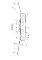
図1は、本発明に係る第1実施形態であるインクジェットプリンタの全体的な構成を示す概略側面図である。図1に示すように、インクジェットプリンタ101は、4つのインクジェットヘッド1を有するカラーインクジェットプリンタである。このインクジェットプリンタ101には、図中左方に給紙部11が、図中右方に排紙部12がそれぞれ構成されている。
<First Embodiment>
FIG. 1 is a schematic side view showing an overall configuration of an ink jet printer according to a first embodiment of the present invention. As shown in FIG. 1, the
インクジェットプリンタ101の内部には、給紙部11から排紙部12に向かって用紙(被記録媒体)Pが搬送される用紙搬送経路が形成されている。給紙部11のすぐ下流位置には、用紙を狭持搬送する一対の送りローラ5a、5bが配置されている。一対の送りローラ5a、5bは、用紙Pを給紙部11から図中右方に送り出す。用紙搬送経路の中間部には、2つのベルトローラ6、7と、両ローラ6、7の間に架け渡されるように巻き回されたエンドレスの搬送ベルト8と、搬送ベルト8によって囲まれた領域内においてインクジェットヘッド1と対向する位置に配置されたプラテン15とを含むベルト搬送機構13が設けられている。プラテン15は、インクジェットヘッド1と対向する領域において搬送ベルト8が下方に撓まないように搬送ベルト8を支持する。ベルトローラ7と対向する位置には、ニップローラ4が配置されている。ニップローラ4は、給紙部11から送りローラ5a、5bによって送り出された用紙Pを搬送ベルト8の外周面8aに押さえ付ける。
Inside the
図示しない搬送モータがベルトローラ6を回転させることによって、搬送ベルト8が駆動される。これにより、搬送ベルト8が、ニップローラ4によって外周面8aに押さえ付けられた用紙Pを粘着保持しつつ排紙部12に向けて搬送する。
The conveyor belt 8 is driven by a conveyor motor (not shown) rotating the belt roller 6. Thereby, the conveyance belt 8 conveys the paper P pressed against the outer
用紙搬送経路に沿う搬送ベルト8のすぐ下流には、剥離機構14が設けられている。剥離機構14は、搬送ベルト8の外周面8aに粘着されている用紙Pを外周面8aから剥離して、図中左方の右方の排紙部12に向けて送るように構成されている。
A
4つのインクジェットヘッド1は、4色のインク(マゼンタ、イエロー、シアン、ブラック)に対応して、搬送方向に沿って4つ並べて固定されている。つまり、このインクジェットプリンタ101は、ライン式プリンタである。4つのインクジェットヘッド1は、その下端にヘッド本体2をそれぞれ有している。ヘッド本体2は、搬送方向に直交した方向に長尺な細長い直方体形状となっている。また、ヘッド本体2の底面が外周面8aに対向するインク吐出面2aとなっている。搬送ベルト8によって搬送される用紙Pが4つのヘッド本体2のすぐ下方を順に通過する際に、この用紙Pの上面すなわち印刷面に向けてインク吐出面2aから各色のインクが吐出されることで、用紙Pの印刷面に所望のカラー画像を形成できるようになっている。
The four inkjet heads 1 are fixed side by side along the transport direction corresponding to four color inks (magenta, yellow, cyan, and black). That is, the
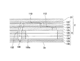
次に、図2を参照しつつインクジェットヘッド1について詳細に説明する。図2は、インクジェットヘッド1の幅方向に沿った断面図である。図2に示すように、インクジェットヘッド1は、その下端に、流路ユニット9と4つのアクチュエータユニット21とが接着剤を介して接合されたヘッド本体2を有している。ヘッド本体2の上面には、ヘッド本体2にインクを供給するリザーバユニット71が固定されている。アクチュエータユニット21の上面には、COF(Chip On Film)50の一端付近が固定されている。COF50は、ドライバIC52が実装された平型柔軟基板である。COF50の他端は、制御基板54と電気的に接続されている。制御基板54は、ドライバIC52を介してアクチュエータユニット21の駆動を制御する。ドライバIC52は、アクチュエータユニット21を駆動する駆動信号を生成する。
Next, the inkjet head 1 will be described in detail with reference to FIG. FIG. 2 is a cross-sectional view taken along the width direction of the inkjet head 1. As shown in FIG. 2, the inkjet head 1 has a head
4つのアクチュエータユニット21、リザーバユニット71、COF50及び制御基板54は、サイドカバー53及びヘッドカバー55によって覆われている。金属板であるサイドカバー53は、流路ユニット9の上面の幅方向両端近傍に固定されており、流路ユニット9の長手方向に沿って延在している。ヘッドカバー55は、2つのサイドカバー53の上端にこれらを跨ぐように固定されている。
The four
リザーバユニット71は、4枚のプレート91〜94が積層されたものであり、その内部に、図示しないインク流入流路、インクリザーバ61、及び、10個のインク流出流路62が互いに連通するように形成されている。なお、図2においては、1つのインク流出流路62のみが表れている。インク流入流路には、図示しないインクタンクからのインクが流入する。インクリザーバ61は、インク流入流路及びインク流出流路62と連通しており、インクを一時的に貯溜する。インク流出流路62は、流路ユニット9の上面に形成されたインク供給口105b(図3参照)を介して流路ユニット9と連通している。インクタンクからのインクは、インク流入流路、インクリザーバ61及びインク流出流路62を通過し、インク供給口105bから流路ユニット9に供給される。プレート94の下面は、プレート94とCOF50との間に間隙が形成されるように、凹凸面となっている。
The
COF50は、サイドカバー53とリザーバユニット71との間に挟まれつつ延在している。そして、COF50の他端は、制御基板54に実装されたコネクタ54aに接続されている。ドライバIC52は、リザーバユニット71の側面に貼り付けられたスポンジ82によってサイドカバー53に向けて付勢されている。
The
次に、図3〜図6を参照しつつ、ヘッド本体2について説明する。図3は、ヘッド本体2の平面図である。図4は、図3の一点鎖線で囲まれた領域の拡大図である。なお、図4では、実線で描くべきアクチュエータユニット21を破線で、アクチュエータユニット21の下方にあって破線で描くべき圧力室110、アパーチャ112及びインク吐出口108を実線で描いている。図5は、図4に示すV−V線に沿った断面図である。図6(a)はアクチュエータユニット21の拡大断面図であり、図6(b)は、図6(a)においてアクチュエータユニット21の表面に配置された個別電極を示す平面図である。なお、アクチュエータユニット21とキャビティプレート122との間には、これらを接合する薄い接着剤層146(図10参照)が存在しているが、図6(a)ではその図示を省略している。
Next, the
図3に示すように、ヘッド本体2は、流路ユニット9、及び、流路ユニット9の上面9aに固定された4つのアクチュエータユニット21を含んでいる。図4に示すように、流路ユニット9の内部には、圧力室110を含むインク流路が形成されている。アクチュエータユニット21は、各圧力室110に対応した複数のアクチュエータを含んでおり、圧力室110内のインクに選択的に吐出エネルギーを付与する機能を有する。
As shown in FIG. 3, the
流路ユニット9は、リザーバユニット71のプレート94とほぼ同じ平面形状を有する直方体形状となっている。流路ユニット9の上面9aには、リザーバユニット71のインク流出流路62(図2参照)に対応して、計10個のインク供給口105bが設けられている。流路ユニット9の内部には、インク供給口105bに連通するマニホールド流路105及びマニホールド流路105から分岐した副マニホールド流路105aが形成されている。流路ユニット9の下面は、図4及び図5に示すように、多数のインク吐出口108がマトリクス状に配置されたインク吐出面2aである。流路ユニット9の上面には、多数の圧力室110が、インク吐出口108と同様に、マトリクス状に多数配列されている。
The
本実施形態では、等間隔に配置された複数の圧力室110からなる流路ユニット9の長手方向に延びた圧力室110の列が、1つのアクチュエータユニット21内に16列形成されている。各圧力室列に含まれる圧力室110の数は、アクチュエータユニット21のの長辺(下底)に近いものほど多く、短辺(上底)に近いものほど少ない。インク吐出口108についても同様である。
In the present embodiment, 16 rows of
図5に示すように、流路ユニット9は、上から順に、キャビティプレート122、ベースプレート123、アパーチャプレート124、サプライプレート125、3枚のマニホールドプレート126、127、128、カバープレート129、及び、ノズルプレート130、という9枚のステンレス鋼等の金属プレートから構成されている。これらプレート122〜130は、主走査方向に長尺な矩形平面形状を有する。これらプレート122〜130を互いに位置合わせしつつ積層することによって、流路ユニット9内に、マニホールド流路105、副マニホールド流路105a、及び、副マニホールド流路105aの出口から絞りとして機能するアパーチャ112さらに圧力室110を経てインク吐出口108に至る多数の個別インク流路132が形成される。
As shown in FIG. 5, the
次に、アクチュエータユニット21について説明する。図3に示すように、各アクチュエータユニット21は台形の平面形状を有している。4つのアクチュエータユニット21は、インク供給口105bを避けるよう主走査方向に千鳥状に配置されている。各アクチュエータユニット21の平行対向辺は流路ユニット9の長手方向に沿っている。隣接するアクチュエータユニット21の斜辺同士は、主走査方向に関して互いにオーバーラップしている。
Next, the
図6(a)に示すように、アクチュエータユニット21は、強誘電性を有するチタン酸ジルコン酸鉛(PZT)系のセラミックス材料からなる3枚の圧電層141〜143が積層された圧電体を含んでいる。最上層である圧電層141の上面であって圧力室110に対向する領域には、個別電極135が形成されている。最上層である圧電層141とその下側の圧電層142との間には、シート全面に形成された共通電極134が介在している。個別電極135は、図6(b)に示すように、圧力室110と相似な略菱形の平面形状を有する。平面視で、個別電極135の大部分は、圧力室110の領域内にある。略菱形の個別電極135における鋭角部の一方は圧力室110の外に延出され、その先端には個別電極135と電気的に接続された円形の個別ランド136が設けられている。個別ランド136は、個別電極135よりも厚い。また、圧電層141の表面には、共通電極134と電気的に接続されたCOMランド138、139(図8及び図9参照)が形成されている。
As shown in FIG. 6A, the
共通電極134及び個別電極135は、それぞれ、COF50に設けられた配線を介してドライバIC52と接続されている。共通電極134には、グランド電位に保持された信号がドライバIC52から供給される。個別電極135には、印字すべき画像パターンに応じてグランド電位と正電位とを交互に取る駆動信号がドライバIC52から供給される。
The
圧電層141はその厚み方向に分極されている。個別電極135を共通電極134と異なる電位にして圧電層141の個別電極135と共通電極134とに挟まれた部分(活性部)に対してその分極方向に電界を印加すると、活性部が圧電効果で歪む。例えば、分極方向と電界の印加方向とが同じであれば、活性部は分極方向に直交する方向(平面方向)に縮む。一方、圧電層142、143は自発的に歪むことはない非活性層である。このとき、圧電層141〜143は圧力室110を区画するキャビティプレート122の上面に固定されているので、ユニモルフ効果が生じる。その結果、圧電層141〜143の活性部に相当する領域が圧力室110に向かって凸になるように変形する。このようなユニモルフ変形が生じることで、圧力室110内のインクに圧力つまり吐出エネルギーが付与され、インク吐出口108からインク滴が吐出される。このように、アクチュエータユニット21において、個別電極135と圧力室110との間に挟まれた部分が、個別のアクチュエータとして働くので、アクチュエータユニット21には、圧力室110の数と同数のアクチュエータが形成されていることになる。
The
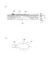
次に、キャビティプレート122の詳細について、図7〜図10を参照して説明する。図7は、キャビティプレート122の部分平面図である。キャビティプレート122において、圧力室110は、貫通孔として形成されている。そして、キャビティプレート122に形成された多数の圧力室110は、互いに同じ台形形状を有する4つの圧力室群151(図7に示す範囲内にはそのうちの2つだけが表れている)を構成している。各圧力室群151は、アクチュエータユニット21とほぼ同じ寸法を有している。
Next, details of the
キャビティプレート122には、4つの圧力室群151をそれぞれ個別に取り囲む台形枠形状を有する4つの環状溝153が形成されている。環状溝153は、キャビティプレート122を貫通していない凹部となっている。環状溝153の両斜辺からは、短辺及び長辺に平行であって比較的短い多数の矩形溝155が延びている。すべての矩形溝155は、環状溝153と連結されている。多数の矩形溝155は等間隔に形成されている。隣接する2つの環状溝153に係る対向した2つの斜辺からそれぞれ延びた多数の矩形溝155は、先端同士において互いに連結されている。環状溝153及び矩形溝155は、これら以外の部分をマスクしたハーフエッチングをキャビティプレート122に施すことによって形成される。
The
図8及び図9は、それぞれ、キャビティプレート122上にアクチュエータユニット21が配置された状態における、図7に示す領域A及び領域Bの拡大平面図である。図10は、図8に示すX−X線に沿った断面図である。図10においては、アクチュエータユニット21の積層構造の図示を省略している。図8〜図10に示すように、アクチュエータユニット21の外縁は、その全周にわたって、環状溝153と対向している。なお、図7〜図9において、アクチュエータユニット21の最外周に描かれた圧力室及び個別電極は、インク吐出を行わないダミーとして形成されたものである。
8 and 9 are enlarged plan views of the region A and the region B shown in FIG. 7 in a state where the
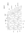
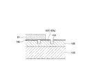
環状溝153の底面からは、支持体である多数の支持柱157が突出している。支持柱157は、キャビティプレート122の一部分である。支持柱157には、環状溝153の長辺に沿って形成されたもの157aと、環状溝153の短辺に沿って形成されたもの157bと、環状溝153の斜辺に沿って形成されたもの157cと、環状溝153の4つの角部に形成されたもの157dとがある。いずれの支持柱157も、アクチュエータユニットの外縁と対向しつつ、環状溝153の延在方向に沿って並んでいる。そして、いずれの支持柱157も、環状溝153の内側壁面及び外側壁面から離隔した島状となっている。支持柱157の高さは環状溝153の深さと同じであるので、図10に示すように、支持柱157は、アクチュエータユニット21とキャビティプレート122とを接合する接着剤層146を介して、アクチュエータユニット21と密着している。これによって、支持柱157は、アクチュエータユニット21を下方から支えている。支持柱157は、キャビティプレート122に環状溝153及び矩形溝155を形成する際のエッチング加工において支持柱157に相当する部分をマスクすることによって、環状溝153及び矩形溝155と同時に形成される。
From the bottom surface of the
環状溝153の長辺に設けられた多数の支持柱157aは、等間隔で配置されている。また、環状溝153の短辺に設けられた多数の支持柱157bは、支持柱157aと同じ等間隔で配置されている。環状溝153の斜辺に設けられた多数の支持柱157cは、支持柱157aとは異なる等間隔で配置されている。
A number of
支持柱157aは、平面視において、副走査方向に長い長方形形状となっている。そのため、製造誤差に起因して、アクチュエータユニット21が副走査方向に位置ずれしたとしても、アクチュエータユニット21の外縁が支持柱157aと対向している可能性が高い。すなわち、アクチュエータユニット21の流路ユニット9に対する副走査方向への位置ずれの許容誤差が大きい。
The
長辺における環状溝153の幅は、外側壁面及び内側壁面が内側と外側にそれぞれ凹むことによって、支持柱157aの周辺において、それ以外の場所に比べて大きくなっている。これによって、製造誤差に起因して、支持柱157aが環状溝153の内側壁面又は外側壁面と連結されて島状でなくなることを防止している。
The width of the
上記のような構造を有するインクジェットヘッドの製造過程において、キャビティプレート122とアクチュエータユニット21とが接合されるとき、両者の間からはみ出した接着剤が環状溝153内に流れ込む。このとき、アクチュエータユニット21の側面の大部分は両者の境界から離れている。そのため、接着剤がアクチュエータユニット21の側面をせり上がってアクチュエータユニット21の上面に付着する接着剤の量が少なくなる。したがって、アクチュエータユニット21の上面に接着剤が付着することによって生じる吐出不良が抑制される。接着剤は、環状溝153に連結された矩形溝155内にも流れ込む。そのため、アクチュエータユニット21の側面をせり上がる接着剤の量が非常に少なくなる。また、矩形溝155が主走査方向に細長く形成されているので、接着剤がキャビティプレート122の上面にその長手方向に沿って順次転写されたときに、矩形溝155が接着剤を収容するので、環状溝153の斜辺の大部分が接着剤で埋め込まれるのが防止される。よって、キャビティプレート122とアクチュエータユニット21とが接合されるときに、環状溝153内に多量の接着剤が流れ込むので、アクチュエータユニット21の側面をせり上がる接着剤の量がより一層少なくなる。
In the manufacturing process of the ink jet head having the above structure, when the
また、本実施形態では、アクチュエータユニット21の外縁と対向する支持柱157がアクチュエータユニット21を支えているので、流路ユニット9に接着剤を介してアクチュエータユニット21を接合する際に、アクチュエータユニット21に加えられた押圧力が、アクチュエータユニット21を介して支持柱157に加えられることになる。そのため、アクチュエータユニット21に作用する剪断力が大幅に小さくなって、アクチュエータユニット21にクラックが生じにくくなる。また、アクチュエータユニット21の外縁が環状溝153と対向しているので、アクチュエータユニット21の全周にわたってその上面に接着剤が付着しにくくなる。
In the present embodiment, since the
さらに、支持柱157が環状溝153の内側壁面及び外側壁面から離隔した島状であるので、流路ユニット9とアクチュエータユニット21との接合時に、キャビティプレート122上面の支持柱157以外の部分に塗布された接着剤が環状溝153によって前記部分から隔てられた支持柱157上に付着することがないので、アクチュエータユニット21の上面により一層接着剤が付着しにくくなる。
Further, since the
本実施形態に係るインクジェットヘッドでは、流路ユニット9とアクチュエータユニット21との接合時には、支持柱157がアクチュエータユニット21の下面と接着剤を介して密着することになるので、アクチュエータユニット21の支持柱157と密着する範囲内では、接着剤がアクチュエータユニット21の側面をせり上がってその上面に到達し得る。本実施形態のように、環状溝153内に、環状溝153の延在方向に沿って複数の支持柱157が並んでいることで、個々の支持柱157を寸法の小さいものとすることができるので、アクチュエータユニット21の上面に接着剤が付着しにくくなる。しかも、複数の支持柱157が配置された、アクチュエータユニット21のより広い範囲においてクラックを生じにくくすることができる。
In the ink jet head according to the present embodiment, when the
そして、これら複数の支持柱157が長辺、短辺、斜辺のそれぞれで等間隔で配置されているので、支持柱157の数をアクチュエータユニット21にクラックが生じない最低の数に近い非常に少ない数とすることが可能となる。したがって、アクチュエータユニット21の上面により一層接着剤が付着しにくくなる。
Since the plurality of
また、本実施形態のインクジェットヘッドでは、アクチュエータユニット21が台形形状を有しており、支持柱157dがアクチュエータユニット21の角部と対向している。これにより、クラックが生じやすい角部にクラックが生じるのを防いでいる。
In the ink jet head of the present embodiment, the
<第2実施形態>
次に、本発明の第2実施形態について図11及び図12をさらに参照して説明する。図11は、本発明の第2実施形態に係るインクジェットヘッドの、図8に相当する平面図である。図12は、図11に示すXII−XII線に沿った断面図である。本実施形態は、支持体が環状溝の内側壁面と連結されていて、島状になっていない点においてのみ、第1実施形態と相違している。したがって、第1実施形態と重複する部分についての説明を省略する。
Second Embodiment
Next, a second embodiment of the present invention will be described with further reference to FIGS. FIG. 11 is a plan view corresponding to FIG. 8 of an inkjet head according to a second embodiment of the present invention. 12 is a cross-sectional view taken along line XII-XII shown in FIG. This embodiment is different from the first embodiment only in that the support is connected to the inner wall surface of the annular groove and is not island-shaped. Therefore, the description about the part which overlaps with 1st Embodiment is abbreviate | omitted.
図11に示すように、本実施形態においても、キャビティプレート122には、4つの圧力室群151をそれぞれ個別に取り囲む台形枠形状を有する4つの環状溝163が形成されている(図11ではそのうち1つの環状溝163の一部が描かれている)。環状溝163の両斜辺からは、短辺及び長辺に平行であって比較的短い多数の矩形溝165が延びている。すべての矩形溝165は、環状溝163と連結されている。
As shown in FIG. 11, also in this embodiment, the
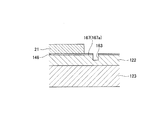
アクチュエータユニット21の外縁は、その全周にわたって、環状溝163と対向している。環状溝163の内側壁面からは、支持体である多数の支持突起167が環状溝163の外側に向かって突出している。支持突起167は、環状溝163の底面に連結されている。支持突起167は、キャビティプレート122の一部分である。支持突起167は、環状溝163の外側壁面に達しておらず、環状溝163を閉鎖していない。
The outer edge of the
支持突起167には、環状溝163の長辺に沿って形成されたもの167aと、環状溝163の短辺に沿って形成されたもの(図示せず)と、環状溝163の斜辺に沿って形成されたもの167cと、環状溝163の4つの角部に形成されたもの167dとがある。いずれの支持突起167も、アクチュエータユニットの外縁と対向しつつ、環状溝163の延在方向に沿って並んでいる。支持突起167の高さは環状溝163の深さと同じであるので、図12に示すように、支持突起167は、接着剤層146を介してアクチュエータユニット21と密着している。これによって、支持突起167は、アクチュエータユニット21を下方から支えている。
The support protrusions 167 include one formed along the long side of the
環状溝163の長辺に設けられた多数の支持突起167aは、等間隔で配置されている。また、環状溝163の短辺に設けられた多数の支持柱は、支持突起167aと同じ等間隔で配置されている。環状溝163の斜辺に設けられた多数の支持突起167cは、支持突起167aとは異なる等間隔で配置されている。
A number of
支持突起167aは、平面視において、副走査方向に長い長方形形状となっている。そのため、製造誤差に起因して、アクチュエータユニット21が副走査方向に位置ずれしたとしても、アクチュエータユニット21の外縁が支持突起167aと対向している可能性が高い。すなわち、アクチュエータユニット21の流路ユニット9に対する副走査方向への位置ずれの許容誤差が大きい。
The
長辺における環状溝163の幅は、外側壁面が外側に凹むことによって、支持突起167aの周辺において、それ以外の場所に比べて大きくなっている。これによって、製造誤差に起因して、支持突起167aが環状溝163の外側壁面と連結されることを防止している。
The width of the
本実施形態によっても、環状溝163内に支持突起167aが設けられていることによって、流路ユニット9とアクチュエータユニット21との接合時にアクチュエータユニット21にクラックが生じにくくなる。そのほか、支持突起167が島状でないことを除いて、第1実施形態と同様の効果が得られる。
Also in the present embodiment, the
<第3実施形態>
次に、本発明の第3実施形態について図13をさらに参照して説明する。図13は、本発明の第3実施形態に係るインクジェットヘッドの、図8に相当する平面図である。本実施形態は、圧力室群を取り囲む溝が環状溝となっていない点においてのみ、第1実施形態と相違している。したがって、第1実施形態と重複する部分についての説明を省略する。
<Third Embodiment>
Next, a third embodiment of the present invention will be described with further reference to FIG. FIG. 13 is a plan view corresponding to FIG. 8 of an inkjet head according to a third embodiment of the present invention. This embodiment is different from the first embodiment only in that the groove surrounding the pressure chamber group is not an annular groove. Therefore, the description about the part which overlaps with 1st Embodiment is abbreviate | omitted.
図13に示すように、本実施形態においては、キャビティプレート122に形成された4つの圧力室群151は、複数の外周溝173によってそれぞれ個別に取り囲まれている(図13ではそのうち1つの圧力室群についてその一部が描かれている)。外周溝173には、アクチュエータユニット21の長辺に沿って形成されたもの173aと、アクチュエータユニット21の短辺に沿って形成されたもの(図示せず)と、アクチュエータユニット21の斜辺に沿って形成されたもの173cとがある。外周溝173cからは、アクチュエータユニット21の短辺及び長辺に平行であって比較的短い多数の矩形溝175が延びている。すべての矩形溝175は、外周溝173cと連結されている。
As shown in FIG. 13, in this embodiment, the four
アクチュエータユニット21の外縁は、隣接する外周溝173の間を除いて、その全周にわたって、外周溝173と対向している。各外周溝173の底面からは、支持体である一又は複数の支持柱177が突出している。支持柱177は、キャビティプレート122の一部分である。支持柱177には、外周溝173a内に形成されたもの177aと、アクチュエータユニット21の短辺に沿って形成された外周溝内に形成されたもの(図示せず)と、外周溝173c内に形成されたもの177c(支持柱177dに該当するものを除く)と、アクチュエータユニット21の4つの角部に形成されたもの177dとがある。外周溝173a内には支持柱177aが1つだけ形成されている。なお、本実施形態では、外周溝173c内に支持柱177dがあるが、支持柱177dは、外周溝173a内、又は、アクチュエータユニット21の短辺に沿って形成された外周溝内に形成されていてもよい。
The outer edge of the
いずれの支持柱177も、アクチュエータユニット21の外縁と対向している。そして、いずれの支持柱177も、外周溝173の内側壁面及び外側壁面から離隔した島状となっている。支持柱177の高さは外周溝173の深さと同じであるので、支持柱177は、アクチュエータユニット21とキャビティプレート122とを接合する接着剤層146を介して、アクチュエータユニット21と密着している。これによって、支持柱177は、アクチュエータユニット21を下方から支えている。
Any of the
支持柱177は、アクチュエータユニット21の長辺、短辺、斜辺のそれぞれにおいて、等間隔で配置されている。
The
支持柱177aは、平面視において、副走査方向に長い長方形形状となっている。そのため、製造誤差に起因して、アクチュエータユニット21が副走査方向に位置ずれしたとしても、アクチュエータユニット21の外縁が支持柱177aと対向している可能性が高い。すなわち、アクチュエータユニット21の流路ユニット9に対する副走査方向への位置ずれの許容誤差が大きい。
The
外周溝173aの幅は、内側壁面及び外側壁面が内側と外側にそれぞれ凹むことによって、支持柱177aの周辺において、それ以外の場所に比べて大きくなっている。これによって、製造誤差に起因して、支持柱177aが外周溝173aの内側壁面又は外側壁面と連結されることを防止している。
The width of the outer
本実施形態によっても、外周溝173内に支持柱177が設けられていることによって、流路ユニット9とアクチュエータユニット21との接合時にアクチュエータユニット21にクラックが生じにくくなる。そのほか、外周溝173が環状となっていないことを除いて、第1実施形態と同様の効果が得られる。また、圧力室群が形成された領域とその外側の領域とが隣接する外周溝173同士の間にある複数の個所で連結されているため、その分キャビティプレート122の剛性の低下が抑えられている。
Also according to the present embodiment, the
以上のように、いずれの実施形態でも、アクチュエータユニット21は支持柱157、177又は支持突起167に支持されて流路ユニット9に固定されている。これをインクジェットヘッド1に組み立てるとき、COF50の端子部に接合される個別ランド136は、印刷法で個別電極135上に形成される。個別ランド136を形成するとき、開口を有するマスクをアクチュエータユニット21上に配置し、マスクに沿ってスキージを移動させしながら導電性のペーストを個別電極135上に転写する。このとき、スキージをヘッドの長手方向に移動させるので、アクチュエータユニット21の角部や端部に一時的に応力が集中することがある。しかし、支持柱157、177又は支持突起167がアクチュエータユニット21を下から支えているので、押圧力集中でアクチュエータユニット21が破損することもない。
As described above, in any of the embodiments, the
以上、本発明の好適な実施形態について説明したが、本発明は上述の実施形態に限られるものではなく、特許請求の範囲に記載した限りにおいて様々な設計変更を上述の実施形態に施すことが可能である。例えば、アクチュエータユニット21は台形以外の平面形状を有していてもよい。また、支持体がアクチュエータユニット21の角部と対向していなくてもよい。さらに、支持体がキャビティプレート122の一部分ではなく、別体(例えばベースプレート123の一部)として形成されていてもよい。
The preferred embodiments of the present invention have been described above, but the present invention is not limited to the above-described embodiments, and various design changes can be made to the above-described embodiments as long as they are described in the claims. Is possible. For example, the
1 インクジェットヘッド
2 ヘッド本体
9 流路ユニット
21 アクチュエータユニット
50 COF
54 制御基板
52 ドライバIC
71 リザーバユニット
101 インクジェットプリンタ
108 インク吐出口
110 圧力室
122 キャビティプレート
132 個別インク流路
134 共通電極
135 個別電極
136 個別ランド
141〜143 圧電層
146 接着剤層
151 圧力室群
153 163 環状溝
155 165 175 矩形溝
157(157a、157b、157c、157d) 支持柱(支持体)
167(167a、167c、167d) 支持突起(支持体)
173(173a、173c) 外周溝
177(177a、177c、177d) 支持柱(支持体)
DESCRIPTION OF SYMBOLS 1
54
71
167 (167a, 167c, 167d) Support protrusion (support)
173 (173a, 173c) Peripheral groove 177 (177a, 177c, 177d) Support column (support)
Claims (9)
前記複数の圧力室を覆うように前記流路ユニットの前記表面に接着剤を介して接合された圧電アクチュエータユニットとを備え、
前記流路ユニットの前記表面には、前記複数の圧力室を取り囲む環状の溝が形成され、
平面視で前記圧電アクチュエータユニットの外縁がその全周に亘って前記溝と対向しており、
前記溝内には、前記圧電アクチュエータユニットの外縁と対向しつつ前記圧電アクチュエータユニットの外縁を支える支持体が設けられており、
前記支持体は、前記溝の延在方向に沿った長さよりも前記溝の延在方向と直交する方向に沿った長さの方が長いことを特徴とする液体吐出ヘッド。 A flow path unit having a plurality of individual liquid flow paths including pressure chambers, and a surface on which a plurality of openings of the plurality of pressure chambers are formed;
A piezoelectric actuator unit joined to the surface of the flow path unit via an adhesive so as to cover the plurality of pressure chambers;
An annular groove surrounding the plurality of pressure chambers is formed on the surface of the flow path unit,
The outer edge of the piezoelectric actuator unit is opposed to the groove over the entire circumference in plan view ,
In the groove, a support body that supports the outer edge of the piezoelectric actuator unit while facing the outer edge of the piezoelectric actuator unit is provided ,
The liquid discharge head according to claim 1, wherein the support has a longer length along a direction perpendicular to the extending direction of the groove than a length along the extending direction of the groove .
前記複数の圧力室を覆うように前記流路ユニットの前記表面に接着剤を介して接合された圧電アクチュエータユニットとを備え、
前記流路ユニットの前記表面には、前記複数の圧力室を取り囲む一又は複数の溝が形成され、
平面視で前記圧電アクチュエータユニットの外縁が、隣接する溝の間を除いてその全周に亘って前記溝と対向しており、
前記溝内には、前記圧電アクチュエータユニットの外縁と対向しつつ前記圧電アクチュエータユニットの外縁を支える支持体が前記溝の側壁面から離隔した島状となるように設けられており、
前記支持体は、前記溝の延在方向に沿った長さよりも前記溝の延在方向と直交する方向に沿った長さの方が長いことを特徴とする液体吐出ヘッド。 A flow path unit having a plurality of individual liquid flow paths including pressure chambers, and a surface on which a plurality of openings of the plurality of pressure chambers are formed;
A piezoelectric actuator unit joined to the surface of the flow path unit via an adhesive so as to cover the plurality of pressure chambers;
One or a plurality of grooves surrounding the plurality of pressure chambers are formed on the surface of the flow path unit,
The outer edge of the piezoelectric actuator unit in plan view is opposed to the groove over the entire circumference except between adjacent grooves ,
In the groove, a support body that supports the outer edge of the piezoelectric actuator unit while facing the outer edge of the piezoelectric actuator unit is provided so as to have an island shape separated from the side wall surface of the groove ,
The liquid discharge head according to claim 1, wherein the support has a longer length along a direction perpendicular to the extending direction of the groove than a length along the extending direction of the groove .
前記圧電アクチュエータユニットが、台形平面形状を有し、The piezoelectric actuator unit has a trapezoidal planar shape;
前記複数の圧電アクチュエータユニットは、前記圧電アクチュエータユニットの平行対向辺が前記一方向に沿うとともに、隣接する圧電アクチュエータユニットの斜辺同士が一方向にオーバーラップするように、前記流路ユニットの前記表面に前記一方向に並んで配置され、The plurality of piezoelectric actuator units are arranged on the surface of the flow path unit such that parallel opposing sides of the piezoelectric actuator units are along the one direction, and oblique sides of adjacent piezoelectric actuator units overlap in one direction. Arranged in one direction,
前記流路ユニットの前記表面には、前記平行対向辺と平行に延びており前記溝の前記圧電アクチュエータユニットの両斜辺に対向する部分と連結された複数の矩形溝が形成されていることを特徴とする請求項1〜8のいずれか1項に記載の液体吐出ヘッド。The surface of the flow path unit is formed with a plurality of rectangular grooves that extend in parallel with the parallel opposing sides and are connected to portions of the grooves facing both oblique sides of the piezoelectric actuator unit. The liquid discharge head according to any one of claims 1 to 8.
Priority Applications (4)
| Application Number | Priority Date | Filing Date | Title |
|---|---|---|---|
| JP2007043919A JP4353261B2 (en) | 2007-02-23 | 2007-02-23 | Liquid discharge head |
| EP08003198A EP1961571B8 (en) | 2007-02-23 | 2008-02-21 | Liquid ejection head |
| US12/035,026 US7726784B2 (en) | 2007-02-23 | 2008-02-21 | Liquid ejection head |
| CN2008100813302A CN101249749B (en) | 2007-02-23 | 2008-02-25 | Liquid ejection head |
Applications Claiming Priority (1)
| Application Number | Priority Date | Filing Date | Title |
|---|---|---|---|
| JP2007043919A JP4353261B2 (en) | 2007-02-23 | 2007-02-23 | Liquid discharge head |
Publications (2)
| Publication Number | Publication Date |
|---|---|
| JP2008207363A JP2008207363A (en) | 2008-09-11 |
| JP4353261B2 true JP4353261B2 (en) | 2009-10-28 |
Family
ID=39361482
Family Applications (1)
| Application Number | Title | Priority Date | Filing Date |
|---|---|---|---|
| JP2007043919A Active JP4353261B2 (en) | 2007-02-23 | 2007-02-23 | Liquid discharge head |
Country Status (4)
| Country | Link |
|---|---|
| US (1) | US7726784B2 (en) |
| EP (1) | EP1961571B8 (en) |
| JP (1) | JP4353261B2 (en) |
| CN (1) | CN101249749B (en) |
Families Citing this family (7)
| Publication number | Priority date | Publication date | Assignee | Title |
|---|---|---|---|---|
| JP4720916B2 (en) * | 2009-03-02 | 2011-07-13 | ブラザー工業株式会社 | Recording device |
| US8210660B2 (en) * | 2009-11-23 | 2012-07-03 | Lexmark International, Inc. | High volume ink delivery manifold for a page wide printhead |
| JP5943636B2 (en) * | 2011-04-15 | 2016-07-05 | 株式会社Okiデータ・インフォテック | Recording apparatus and recording method |
| JP6039365B2 (en) * | 2012-10-26 | 2016-12-07 | 京セラ株式会社 | Liquid discharge head and recording apparatus using the same |
| JP6130165B2 (en) * | 2013-02-27 | 2017-05-17 | 京セラ株式会社 | Liquid discharge head and recording apparatus using the same |
| JP6377474B2 (en) * | 2014-09-22 | 2018-08-22 | 京セラ株式会社 | Inkjet head and printer |
| JP2022182303A (en) | 2021-05-28 | 2022-12-08 | ブラザー工業株式会社 | Liquid discharge head |
Family Cites Families (12)
| Publication number | Priority date | Publication date | Assignee | Title |
|---|---|---|---|---|
| CN1167552C (en) * | 1998-06-29 | 2004-09-22 | 财团法人工业技术研究院 | Method for making ink channel |
| DE60003767T2 (en) * | 1999-10-29 | 2004-06-03 | Hewlett-Packard Co. (N.D.Ges.D.Staates Delaware), Palo Alto | Inkjet printhead with improved reliability |
| JP3692895B2 (en) | 2000-03-07 | 2005-09-07 | ブラザー工業株式会社 | Piezoelectric inkjet printer head |
| US6604817B2 (en) * | 2000-03-07 | 2003-08-12 | Brother Kogyo Kabushiki Kaisha | Print head for piezoelectric ink jet printer, piezoelectric actuator therefor, and process for producing piezoelectric actuator |
| US6679595B2 (en) * | 2001-02-08 | 2004-01-20 | Brother Kogyo Kabushiki Kaisha | Ink jet recording apparatus |
| JP3925469B2 (en) * | 2003-06-30 | 2007-06-06 | ブラザー工業株式会社 | Inkjet head |
| JP3876861B2 (en) * | 2003-08-12 | 2007-02-07 | ブラザー工業株式会社 | Inkjet head |
| JP2006076128A (en) * | 2004-09-09 | 2006-03-23 | Fuji Xerox Co Ltd | Inkjet recording head |
| US7455394B2 (en) * | 2004-09-30 | 2008-11-25 | Brother Kogyo Kabushiki Kaisha | Inkjet head |
| JP4207023B2 (en) * | 2005-06-20 | 2009-01-14 | ブラザー工業株式会社 | Inkjet head |
| JP4624884B2 (en) | 2005-08-08 | 2011-02-02 | 株式会社クボタ | Image processing device for work vehicles |
| JP2007045129A (en) * | 2005-08-12 | 2007-02-22 | Seiko Epson Corp | Liquid jetting head and liquid jetting apparatus |
-
2007
- 2007-02-23 JP JP2007043919A patent/JP4353261B2/en active Active
-
2008
- 2008-02-21 EP EP08003198A patent/EP1961571B8/en active Active
- 2008-02-21 US US12/035,026 patent/US7726784B2/en active Active
- 2008-02-25 CN CN2008100813302A patent/CN101249749B/en active Active
Also Published As
| Publication number | Publication date |
|---|---|
| EP1961571B1 (en) | 2012-07-04 |
| CN101249749B (en) | 2010-06-02 |
| CN101249749A (en) | 2008-08-27 |
| EP1961571A1 (en) | 2008-08-27 |
| US7726784B2 (en) | 2010-06-01 |
| US20080204522A1 (en) | 2008-08-28 |
| EP1961571B8 (en) | 2012-08-08 |
| JP2008207363A (en) | 2008-09-11 |
Similar Documents
| Publication | Publication Date | Title |
|---|---|---|
| US9114616B2 (en) | Ink-jet head having passage unit and actuator units attached to the passage unit, and ink-jet printer having the ink-jet head | |
| US7374277B2 (en) | Ink-jet head | |
| JP4206775B2 (en) | Inkjet head | |
| JP4353261B2 (en) | Liquid discharge head | |
| JP2017177676A (en) | Liquid discharge device | |
| JP3951933B2 (en) | Ink jet head and ink jet printer having the same | |
| US6979077B2 (en) | Ink-jet head and ink-jet printer having ink-jet head | |
| JP2008238776A (en) | Liquid ejection head and method of manufacturing the same | |
| JP6115236B2 (en) | Liquid ejecting head, liquid ejecting apparatus, and fixing method | |
| JP2003311959A (en) | Ink jet head and ink jet printer comprising it | |
| JP4110997B2 (en) | Inkjet head, inkjet head manufacturing method, and inkjet printer having inkjet head | |
| JP2009241453A (en) | Liquid drop ejecting device and method for manufacturing the same | |
| JP5997219B2 (en) | Piezoelectric actuator substrate, liquid ejection head using the same, and recording apparatus | |
| JP2005059339A (en) | Ink jet head and ink jet recorder having that ink jet head | |
| JP2003311956A (en) | Inkjet head and inkjet printer comprising it | |
| US8313176B2 (en) | Liquid ejection head | |
| JP3864953B2 (en) | Inkjet head, inkjet head assembly, and inkjet printer including the same | |
| JP4640367B2 (en) | Inkjet head | |
| JP5434932B2 (en) | Liquid discharge head and manufacturing method thereof | |
| JP2005022117A (en) | Inkjet head and printing device | |
| JP7221992B2 (en) | Liquid ejection head and recording device | |
| JP4900218B2 (en) | Liquid transfer device and piezoelectric actuator | |
| JP4930390B2 (en) | Liquid transfer device | |
| JP4540296B2 (en) | Inkjet head manufacturing method | |
| JP2004160942A (en) | Ink jet head and its manufacturing process |
Legal Events
| Date | Code | Title | Description |
|---|---|---|---|
| A977 | Report on retrieval |
Free format text: JAPANESE INTERMEDIATE CODE: A971007 Effective date: 20090129 |
|
| A131 | Notification of reasons for refusal |
Free format text: JAPANESE INTERMEDIATE CODE: A131 Effective date: 20090203 |
|
| A521 | Written amendment |
Free format text: JAPANESE INTERMEDIATE CODE: A523 Effective date: 20090406 |
|
| TRDD | Decision of grant or rejection written | ||
| A01 | Written decision to grant a patent or to grant a registration (utility model) |
Free format text: JAPANESE INTERMEDIATE CODE: A01 Effective date: 20090707 |
|
| A01 | Written decision to grant a patent or to grant a registration (utility model) |
Free format text: JAPANESE INTERMEDIATE CODE: A01 |
|
| A61 | First payment of annual fees (during grant procedure) |
Free format text: JAPANESE INTERMEDIATE CODE: A61 Effective date: 20090720 |
|
| R150 | Certificate of patent or registration of utility model |
Ref document number: 4353261 Country of ref document: JP Free format text: JAPANESE INTERMEDIATE CODE: R150 Free format text: JAPANESE INTERMEDIATE CODE: R150 |
|
| FPAY | Renewal fee payment (event date is renewal date of database) |
Free format text: PAYMENT UNTIL: 20120807 Year of fee payment: 3 |
|
| FPAY | Renewal fee payment (event date is renewal date of database) |
Free format text: PAYMENT UNTIL: 20120807 Year of fee payment: 3 |
|
| FPAY | Renewal fee payment (event date is renewal date of database) |
Free format text: PAYMENT UNTIL: 20130807 Year of fee payment: 4 |