JP4352696B2 - Network-compatible devices and installation location management methods for network-compatible devices - Google Patents
Network-compatible devices and installation location management methods for network-compatible devices Download PDFInfo
- Publication number
- JP4352696B2 JP4352696B2 JP2002368929A JP2002368929A JP4352696B2 JP 4352696 B2 JP4352696 B2 JP 4352696B2 JP 2002368929 A JP2002368929 A JP 2002368929A JP 2002368929 A JP2002368929 A JP 2002368929A JP 4352696 B2 JP4352696 B2 JP 4352696B2
- Authority
- JP
- Japan
- Prior art keywords
- position information
- network
- movement
- compatible device
- information storage
- Prior art date
- Legal status (The legal status is an assumption and is not a legal conclusion. Google has not performed a legal analysis and makes no representation as to the accuracy of the status listed.)
- Expired - Fee Related
Links
Images


Classifications
-
- H—ELECTRICITY
- H04—ELECTRIC COMMUNICATION TECHNIQUE
- H04L—TRANSMISSION OF DIGITAL INFORMATION, e.g. TELEGRAPHIC COMMUNICATION
- H04L41/00—Arrangements for maintenance, administration or management of data switching networks, e.g. of packet switching networks
- H04L41/08—Configuration management of networks or network elements
- H04L41/0893—Assignment of logical groups to network elements
Landscapes
- Engineering & Computer Science (AREA)
- Computer Networks & Wireless Communication (AREA)
- Signal Processing (AREA)
- Mobile Radio Communication Systems (AREA)
- Accessory Devices And Overall Control Thereof (AREA)
- Control Or Security For Electrophotography (AREA)
- Computer And Data Communications (AREA)
- Alarm Systems (AREA)
Description
【0001】
【発明の属する技術分野】
本発明はコンピュータネットワークに接続されたネットワーク対応機器の設置位置を管理する方法に関する。
【0002】
【従来の技術】
インターネットなど、コンピュータネットワークは全世界に広がっている。このコンピュータネットワークには、複写機、プリンタ、FAX、スキャナ、またはこれらを複合した複合機など数多くの機器が接続されている。特に前述したネットワーク対応機器は、情報交換に紙という物理的な媒体を扱うため、設置されている位置という情報は、利用者にとって重要である。そこで、機器管理者は、各々の機器を設置した時に位置情報(たとえば、緯度経度、設置場所の住所や建物/部屋番号など)を内蔵された記憶手段に設定し、各機器から位置情報をネットワークを介して収集することで、各機器の設置位置を管理している。
【0003】
ところで、前述したネットワーク対応機器は、利用者の都合で移動されることがある。このとき、機器管理者は、移動された機器に設定した位置情報を移動先の位置情報で更新する。
【0004】
【発明が解決しようとする課題】
しかしながら、位置情報は、一般にネットワーク対応機器が稼動するうえで必須な情報ではない。つまり、ネットワーク対応機器は、移動前の位置情報が設定されたままの状態でも移動先で稼動可能である。そのため、位置情報は、機器を移動させても変更されないことがあり、これにより、記憶されている設置位置と移動後の位置情報とが一致していないという状況は、容易に発生しうる。この結果、ネットワーク対応機器に位置情報を記憶する手段が設けられていたとしても、その記憶手段を用いたネットワーク対応機器の設置位置の管理を十分に行うことができなかった。機器管理者は、機器を移動するたびに設置位置情報を逐次更新していたとしても、機器利用者が機器管理者の許可無く機器を移動してしまうことがある。このような状況は、ネットワークへの接続台数が膨大になるにつれ発生しやすくなり、ネットワーク対応機器の設置位置の管理は、更に困難になってくる。
【0005】
従って、ネットワーク対応機器が移動され設置されたときには、移動前の設置位置を示す位置情報が設定されたままであるという状態を解消できるようにすることが望ましい。
【0006】
本発明は以上のような問題を解決するためになされたものであり、その目的は、移動されたときに移動前の設置位置を示す位置情報が設定されたままであるという状態を回避することのできるネットワーク対応機器及びネットワーク対応機器における設置位置管理方法を提供することにある。
【0007】
【課題を解決するための手段】
以上のような目的を達成するために、本発明に係るネットワーク対応機器は、設置位置を示す位置情報を記憶する位置情報記憶手段を有し、前記位置情報記憶手段に設定された位置情報によって設置位置が管理され、その設置位置に固定されて使用されるネットワーク対応機器において、前記ネットワーク対応機器の位置に関する状態の変化又は前記ネットワーク対応機器の設置位置を特定するために割り付けられる設定情報の内容の変更を検知することによって前記ネットワーク対応機器の設置位置の移動を検出する移動検出手段と、前記移動検出手段により移動が検出されたときに前記位置情報記憶手段に記憶されている位置情報を消去し、その消去後、移動後の設置位置を示す位置情報が前記位置情報記憶手段に設定されるまで前記ネットワーク対応機器の動作を禁止する防止手段とを有することを特徴とする。
【0008】
本発明に係るネットワーク対応機器は、設置位置を示す位置情報を記憶する位置情報記憶手段を有し、前記位置情報記憶手段に設定された位置情報によって設置位置が管理され、その設置位置に固定されて使用されるネットワーク対応機器において、前記ネットワーク対応機器への電源の供給中断後の再投入を検知することによって設置位置の移動を検出する移動検出手段と、前記移動検出手段により移動が検出されたときに前記位置情報記憶手段に記憶されている位置情報を消去し、その消去後、移動後の設置位置を示す位置情報が前記位置情報記憶手段に設定されるまで前記ネットワーク対応機器の動作を禁止する防止手段と、を有することを特徴とする。
【0022】
また、前記防止手段は、前記移動検出手段により移動が検出されたときに、移動された旨を予め設定した宛先へ通知する通知部と、前記通知部による通知に応じて入力された移動後の設置位置を示す位置情報で前記位置情報記憶手段を更新する位置情報設定部とを有することを特徴とする。
【0025】
また、前記防止手段は、前記位置情報記憶手段に位置情報が設定されていない状態であることを検知したときに警告を出力する警告出力部を有することを特徴とする。
【0029】
本発明に係るネットワーク対応機器における設置位置管理方法は、設置位置を示す位置情報を記憶する位置情報記憶手段を有し、前記位置情報記憶手段に設定された位置情報によって設置位置が管理され、その設置位置に固定されて使用されるネットワーク対応機器において実施され、前記ネットワーク対応機器の位置に関する状態の変化又は前記ネットワーク対応機器の設置位置を特定するために割り付けられる設定情報の内容の変更を検知することによって前記ネットワーク対応機器の設置位置の移動を検出する移動検出ステップと、前記移動検出ステップにより移動が検出されたときに前記位置情報記憶手段に記憶されている位置情報を消去し、その消去後、移動後の設置位置を示す位置情報が前記位置情報記憶手段に設定されるまで前記ネットワーク対応機器の動作を禁止すると共に、移動された旨を予め設定した宛先へ通知する移動検出時ステップと、前記移動検出時ステップによる通知に応じて入力された移動後の設置位置を示す位置情報で前記位置情報記憶手段を更新するステップとを含むことを特徴とする。
【0030】
本発明に係るネットワーク対応機器における設置位置管理方法は、設置位置を示す位置情報を記憶する位置情報記憶手段を有し、前記位置情報記憶手段に設定された位置情報によって設置位置が管理され、その設置位置に固定されて使用されるネットワーク対応機器において実施され、前記ネットワーク対応機器への電源の供給中断後の再投入を検知することによって設置位置の移動を検出する移動検出ステップと、前記移動検出ステップにより移動が検出されたときに前記位置情報記憶手段に記憶されている位置情報を消去し、その消去後、移動後の設置位置を示す位置情報が前記位置情報記憶手段に設定されるまで前記ネットワーク対応機器の動作を禁止すると共に、移動された旨を予め設定した宛先へ通知する移動検出時ステップと、前記移動検出時ステップによる通知に応じて入力された移動後の設置位置を示す位置情報で前記位置情報記憶手段を更新するステップと、を含むことを特徴とする。
【0035】
【発明の実施の形態】
以下、図面に基づいて、本発明の好適な実施の形態について説明する。
【0036】
実施の形態1.
図1は、本発明に係るネットワーク対応機器の一実施の形態を示した構成図である。図1には、移動検出部4、消去部6、警告出力部8、位置情報設定部10、機器動作制御部12及び位置情報記憶部14が示されている。本実施の形態におけるネットワーク対応機器2は、複写機、プリンタ、FAX、スキャナ、またはこれらを複合した複合機などであり、いずれの場合にもネットワーク対応機器として動作するための構成要素は図示するまでもなく当然ながら有している。位置情報記憶部14は、ネットワーク対応機器2が設置された位置を示す位置情報を記憶する記憶装置であり、EPROM(Erasable Programmable Read-Only Memory)などの不揮発性記憶装置で実現される。位置情報記憶部14は、既存の記憶装置をそのまま使用することができる。位置情報は、従来と同様に緯度経度、設置場所の住所や建物/部屋番号などでよい。
【0037】
以下、本実施の形態における構成要素の説明と共に動作について説明する。
【0038】
移動検出部4は、搭載されたネットワーク対応機器2が移動されたことを検出すると、移動検出信号を送出する。消去部6は、移動検出部4が送出した移動検出信号を検出すると、位置情報記憶部14に記憶されている位置情報を強制的に消去する。これにより、移動された後でも移動前の設置位置を示す位置情報(以下、単に「移動前位置情報」)が位置情報記憶部14に設定されたままであるという状態を回避することができる。警告出力部8は、位置情報記憶部14の内容が消去されたことにより位置情報記憶部14に位置情報が設定されていない状態(例えば、オール0又はオール1など)であることを検知すると、位置情報が未設定である旨の警告を出力する。警告は、管理者が気付くように、ネットワーク対応機器2に直接又は間接的に接続された赤ランプを点灯したり、機器管理用装置の表示画面に「位置情報が設定されていません」などの文字を表示する方法がある。あるいは、ネットワーク対応機器2には、通常、機器を操作するためのコントロールパネルがあるので、ここに表示するようにしてもよい。警告出力部8は、位置情報記憶部14に位置情報が設定されたことを確認すると、警告を解除する。
【0039】
また、機器動作制御部12は、位置情報記憶部14から位置情報が消去された後、移動先の設置位置を示す位置情報(以下、単に「移動後位置情報」)が位置情報記憶部14に設定されるまでネットワーク対応機器2の動作を禁止する。これは、ネットワーク対応機器2自体を制御するコントローラ機能部分へのコマンドを発行することでなされる。
【0040】
位置情報設定部10は、警告に応じて管理者により入力されたネットワーク対応機器2の移動後位置情報で位置情報記憶部14を更新する。管理者は、ネットワーク対応機器2に搭載されたコントロールパネル等を操作して、あるいはネットワーク経由で移動先の設置位置を示す情報を入力する。
【0041】
本実施の形態によれば、ネットワーク対応機器2が移動されたことを検出できるようにし、更にネットワーク対応機器2の移動を検出したときには警告を発して管理者に知らせるようにしたので、管理者は、第三者が勝手にネットワーク対応機器2を移動させたとしても、そのネットワーク対応機器2の移動を確実に知ることができる。管理者がこの通知に応じてネットワーク対応機器2の位置情報記憶部14に移動後位置情報を設定登録することにより、移動前位置情報が移動後に位置情報記憶部14に設定されたままであるという状態を回避することができる。
【0042】
更に、本実施の形態においては、機器動作制御部12を設けることによって、位置情報記憶部14に移動後位置情報が設定登録されるまでネットワーク対応機器2を動作させないようにしたので、位置情報記憶手段に設定されている位置情報は、実際に設置位置を示す位置情報と一致することなる。これにより、利用者が位置情報を指定してネットワーク対応機器を探索したとき、その探索により取得できた位置情報は信頼できる位置情報である。従って、固定資産となっているネットワーク対応機器の設置場所管理の省力化、機器の移動の履歴を記録することによるメンテナンスの効率化、更に最適な機器配置を提示することが可能となり、無駄な機器の導入を未然に防止できるなどの効果につながる。
【0043】
ここで、移動検出部4の具体的な構成を図2に示す。本実施の形態における移動検出部4は、ネットワーク対応機器2に設定されているネットワークアドレスが変更されたことによって設置位置が移動されたと判断するアドレス監視部41を有している。
【0044】
ネットワーク対応機器は、機器の識別情報としてネットワーク上のアドレスを必ずもつ。例えば、インターネットの場合は、インターネットプロトコルにより規定される32ビットのアドレスが設定される。このネットワークアドレスは、ネットワーク番号とホスト番号から構成される。ネットワーク番号には、サブネットと呼ばれる物理的に区切られたネットワーク毎に同じ番号が割り付けられる。ホスト番号には、サブネット内で機器を特定するためのアドレスであり、サブネット内で各ネットワーク機器2にユニークな番号が割り付けられる。ネットワーク対応機器2が移動され、移動先のサブネットに接続されると、そのネットワーク対応機器2には、移動先のサブネットにおけるネットワーク番号を含むネットワークアドレスが新たに割り付けられる。そして、このネットワークアドレスがネットワーク対応機器2におけるアドレス保持部21に書き込まれることで、ネットワーク対応機器2は、改めてネットワーク上で認識されることになる。
【0045】
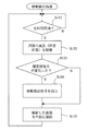
そこで、アドレス監視部41は、図3に示したように、アドレス保持部21で保持されているネットワークアドレスを内部メモリなどに一時記憶しておき、予め設定した一定期間毎にアドレス保持部21に保持されているネットワークアドレスを取得しにいく(ステップ101,102)。そして、アドレス保持部21に設定されているネットワークアドレスと、内部に保持しているネットワークアドレスとを比較し(ステップ103)、一致していないことによりネットワークアドレスが変更されたことを認識する。アドレス監視部41は、ネットワークアドレスが変更されたことをネットワーク対応機器2が移動されたとみなして、移動検出信号を出力する(ステップ104)。そして、アドレス監視部41は、移動検出信号の出力の有無に関係なくアドレス保持部21から取得したネットワークアドレスで内部メモリを更新し、保持する(ステップ105)。
【0046】
ところで、ネットワークアドレスは、通常、ネットワーク対応機器2に固定的に割り付けられているが、近年DHCP(Dynamic Host Configuration Protocol)と呼ばれる自動アドレス割付サービスが使われることがある。DHCPでは、ネットワーク対応機器2が立ち上がる際に、その都度ネットワークアドレスを割り当てるので、この場合、ステップ103においては、ネットワーク番号部分のみを比較することになる。
【0047】
移動検出部4における動作は、以上の通りである。移動検出部4による移動検出後、消去部6が移動検出部4からの移動検出信号を受信してから位置情報記憶部14が移動後位置情報によって更新されるまでの処理については前述した通りである。
【0048】
実施の形態2.
図4は、本実施の形態における移動検出部4を示したブロック構成図である。本実施の形態における移動検出部4は、赤外線発光部42と赤外線センサ部43とを有している。赤外線発光部42は、設置位置から機器外部のいずれかの方向へ向けて発光すると共に発光している期間を示す発光期間信号を赤外線センサ部43へ送る。赤外線センサ部43は、赤外線発光部42が発した赤外線の反射光の強さを発光期間の間で計測し、内蔵したAD変換器でデジタル化して内部メモリに一時記憶する。赤外線センサ部43が反射光を検知できるように、赤外線発光部42と赤外線センサ部43との位置関係や向きは調節される。本実施の形態においては、反射光の受信レベルの変化によってネットワーク対応機器2の移動を検出しようとするものである。
【0049】
本実施の形態における移動検出部4の動作について図5に示したフローチャートを用いて説明すると、赤外線センサ部43は、赤外線の反射光の受信レベルを内部メモリに一時記憶しておき、予め設定した一定期間毎に反射光の強さを計測する(ステップ111,112)。そして、赤外線センサ部43は、計測した反射光の受信レベルと、内部に保持している受信レベルとを比較し(ステップ113)、一致していないことによりネットワーク対応機器2が移動されたと判断し、移動検出信号を出力する(ステップ114)。そして、赤外線センサ部43は、移動検出信号の出力の有無に関係なく計測した反射光の受信レベルで内部メモリを更新し、保持する(ステップ115)。
【0050】
その後に行われる処理、すなわち、消去部6が移動検出部4からの移動検出信号を受信してから位置情報記憶部14が移動後位置情報によって更新されるまでの処理については前述した通りである。
【0051】
以上のように、本実施の形態においても実施の形態1と同様の効果を奏することができる。ところで、本実施の形態の変形例を図6を用いて説明する。図6には、内部時計を有し更に赤外線発光部42と赤外線センサ部43とに同一の時刻情報を与えることで同期させる同期制御部44が示されている。赤外線発光部42には、時刻情報のある発光時刻ごとに発光するように予め設定されており、赤外線センサ部43は、この時刻ごとに赤外線の受信時刻を計測する。赤外線は、機器の外部で反射してくるため発光の時刻から遅れて受信される。発光時刻と受信時刻の差分は、ネットワーク対応機器2と反射体との距離に比例する。赤外線センサ部43は、この時間差を内部メモリに一時記憶する。この変形例では、時間差の変化によってネットワーク対応機器2の移動を検出する。なお、時間差ではなく時間差から求められる距離の差を内部に保持するようにしてもよい。
【0052】
ところで、上記説明では、一定の時間間隔で移動検出を行うようにした。しかしながら、例えば、歩行者が赤外線の光路を横切ったり、ネットワーク対応機器2をテーブル上で移動させたり、あるいはその移動のために一時的に給電を停止する場合もある。従って、記憶しておいた受信レベルと計測した受信レベルとが不一致であったとしても、実際には上記理由により実際には移動されていない、若しくは同じテーブル上で移動させるなど実質的な移動とは認められないような場合もある。従って、移動検出部4に移動検出の誤検出防止機能を設けるようにすることが望ましい。例えば、ステップ113における比較により不一致であったとしても、即座に移動検出信号を出力せずに、その後の受信レベルの状態変化まで考慮して総合的に判断したり、あるいは移動検出部4を電源が供給されて動作可能にしておき、電源断であった時間及び電源断前後の受信レベルを比較したりする。
【0053】
実施の形態3.
図7は、本実施の形態における移動検出部4を示したブロック構成図である。本実施の形態における移動検出部4は、現在位置を計測可能な測位部45を有している。GPS(Global Positioning System)は、自分と複数の人工衛星との距離を計測し、三角測量により地球上の自分の現在位置(緯度と経度)を知ることができる。近年、GPSアンテナや計測および位置計算するCPUはLSI化されているが、測位部45は、このLSI化されたGPSを実装する。
【0054】
本実施の形態における移動検出部4の動作について図8に示したフローチャートを用いて説明すると、測位部45は、計測した現在位置を内部メモリに一時記憶しておき、予め設定した一定期間毎に現在位置を測定する(ステップ121,122)。そして、測位部45は、測定した現在位置と、内部に保持している現在位置とを比較し(ステップ123)、一致していないことによりネットワーク対応機器2が移動されたと判断し、移動検出信号を出力する(ステップ124)。そして、測位部45は、移動検出信号の出力の有無に関係なく測定した現在位置で内部メモリを更新し、保持する(ステップ125)。
【0055】
その後に行われる処理、すなわち、消去部6が移動検出部4からの移動検出信号を受信してから位置情報記憶部14が移動後位置情報によって更新されるまでの処理については前述した通りである。
【0056】
以上のように、本実施の形態においても実施の形態1と同様の効果を奏することができる。また、実施の形態2において説明したように、ネットワーク対応機器2をテーブル上で移動させたり、あるいはその移動のために一時的に給電を停止する場合もあるので、このような場合は移動検出でないとする移動検出の誤検出防止機能を移動検出部4に設けるようにすることが望ましい。
【0057】
実施の形態4.
図9は、本実施の形態における移動検出部4を示したブロック構成図である。本実施の形態における移動検出部4は、リレー電源制御部46、リレー回路47及び信号出力部48を有している。リレー電源制御部46は、商用電源からの電力の供給を監視し、ネットワーク対応機器2の電源コードがACコンセントから抜去された状態であることから商用電源が断たれているとき、及び電源投入時にはリレー回路47への電源供給を一時中断する。また、初期化信号の入力後、リレー回路47への電源を供給を開始する。リレー回路47は、電源が供給されている間は電源断フラグをリセットとし、電源が供給されていないときには電源断フラグをセット状態に維持するリレーである。信号出力部48は、電源投入時に初期化信号を出力し、また、電源断フラグがセット状態であるときには移動検出信号を出力する。
【0058】
以上の構成は、以下のように連係動作する。すなわち、ネットワーク対応機器2の電源コードがACコンセントから抜去されたことにより給電が中断されたとき、リレー電源制御部46は、リレー回路47への電源供給を中断する。電源断に伴い、リレー回路47は、電源断フラグをセット状態に維持する。
【0059】
この後、電源再投入に伴い、信号出力部48は初期化信号を出力する。リレー電源制御部46は、初期化信号の入力に伴いリレー回路47への電源を供給を開始する。リレー回路47は、電源が供給されたことにより電源断フラグをリセットする。更に、リレー電源制御部46は、電源投入時にはリレー回路47への電源供給を一時中断するので、この電源断に伴い、リレー回路47は、電源断フラグをセット状態に維持する。信号出力部48は、電源投入後において電源断フラグがセットされたことに伴い移動検出信号を出力する。なお、この処理は、電源投入後に1回だけ実行される。
【0060】
以上のように、本実施の形態における移動検出部4は、ネットワーク対応機器2への給電状態を監視しておき、ネットワーク対応機器2の電源コードがACコンセントから抜去された後に再度電源が供給されたとき、ACコンセントは、ネットワーク対応機器2の移動先で接続されたとみなして移動検出信号を出力するようにした。
【0061】
その後に行われる処理、すなわち、消去部6が移動検出部4からの移動検出信号を受信してから位置情報記憶部14が移動後位置情報によって更新されるまでの処理については前述した通りである。
【0062】
以上のように、本実施の形態においても実施の形態1と同様の効果を奏することができる。また、実施の形態2,3において説明したように、ネットワーク対応機器2をテーブル上で移動させるために、あるいは消耗品の交換のために一時的に給電を停止する場合もあるので、給電状態の継続時間によって移動か否かを判断するなどの移動検出の誤検出防止機能を移動検出部4に設けるようにすることが望ましい。
【0063】
実施の形態5.
図10は、本実施の形態における移動検出部4を示したブロック構成図である。本実施の形態における移動検出部4は、撮像部49と画像比較部50とを有している。撮像部49は、ネットワーク対応機器2の設置場所からみえる同一箇所の風景を撮像する。撮像部49は、ネットワーク対応機器2から任意の方向の風景を撮影可能であるが、撮影を開始した後は撮影する風景が変わらないように固定される。本実施の形態では、CCDセンサにより光電気変換を行うデジタルカメラで実現する。画像比較部50は、撮像部49による撮影画像を内部メモリに一時記憶し、その後に撮像された画像と記憶している画像とを比較することによってネットワーク対応機器2が移動されたかどうかを判断する。
【0064】
本実施の形態における移動検出部4の動作について図11に示したフローチャートを用いて説明すると、撮像部49は、ネットワーク対応機器2からみた周囲の風景を予め設定した一定期間毎に撮影する(ステップ131,132)。画像比較部50は、撮像部49により撮影されたデジタル画像を内部メモリに一時記憶しているが、撮像部49が風景を撮影したとき、その撮影画像と、内部に保持している撮影画像とを比較する(ステップ133)。そして、一致していないときには、ネットワーク対応機器2が移動されたと判断し、移動検出信号を出力する(ステップ134)。そして、画像比較部50は、移動検出信号の出力の有無に関係なく撮影された画像で内部メモリを更新し、保持する(ステップ135)。
【0065】
その後に行われる処理、すなわち、消去部6が移動検出部4からの移動検出信号を受信してから位置情報記憶部14が移動後位置情報によって更新されるまでの処理については前述した通りである。
【0066】
以上のように、本実施の形態においても実施の形態1と同様の効果を奏することができる。また、実施の形態2,3において説明したように、ネットワーク対応機器2をテーブル上で移動させるために、あるいは歩行者を撮影してしまったりする場合があるので、本実施の形態においても移動検出の誤検出防止機能を移動検出部4に設けるようにすることが望ましい。例えば、ネットワーク対応機器2に電力が供給され作動している間は移動されないと判断し、機器作動中は撮像部49による撮像を中断させるようにしてもよい。あるいは、夜間は光量不足で撮影が困難であるため、また撮影できたとしても撮影画像の比較の精度が十分でないと考え、光量不足を検知したときは撮影を中断してもよい。また、歩行者を撮影してしまった場合を考慮して、ステップ133による比較の結果、一致していないときでも即座に移動検出信号を出力するのではなく、撮影画像の変化が予め設定した基準に達していないときにはじめて設置位置が移動されたと判断するようにすればよい。例えば、所定の複数枚数(例えば5枚)を撮影してそのうち複数枚(例えば3枚)が一致していたときには、移動とみなさないように判断するようにする。
【0067】
以上の各実施の形態においては、種々の構成による移動検出手段を示したが、これらのうち任意の移動検出手段を組み合わせてネットワーク対応機器2に搭載するようにしてもよい。複数の移動検出手段を組み合わせて搭載する場合、複数の移動検出手段全てにおいて移動が検出されてはじめて移動されたと判断されたとするか、あるいは1つでも移動を検出したときに移動されたと判断するかは、移動検出の誤検出防止機能として説明したように、搭載する移動検出手段の数や精度、ネットワーク対応機器2の設置位置等を総合勘案して移動とみなす判断基準を設定すればよい。
【0068】
実施の形態6.
図12は、本発明に係るネットワーク対応機器の他の実施の形態を示した構成図である。図12には、移動検出部4、通知部16、位置情報設定部10及び位置情報記憶部14が示されている。なお、実施の形態1と同じ構成要素には同じ符号を付ける。上記実施の形態1においては、防止手段として消去部6、警告出力部8、位置情報設定部10及び機器動作制御部12を設けて、移動検出部4により移動が検出されたときに、移動前の設置位置を示す位置情報が位置情報記憶部14に記憶されたままの状態であることを防止するようにした。本実施の形態では、防止手段として通知部16及び位置情報設定部10を設けることにした。なお、本実施の形態における移動検出部4は、図1に示したネットワーク対応機器2と同様に、実施の形態1〜5に示した少なくとも1つを用いて実現することができる。
【0069】
以下、本実施の形態における構成要素の説明と共に動作について説明する。
【0070】
移動検出部4は、搭載されたネットワーク対応機器2が移動されたことを検出すると、移動検出信号を送出する。通知部16は、移動検出部4が送出した移動検出信号を検出すると、ネットワーク対応機器2が移動された旨を予め設定した宛先へ通知する。より具体的には、移動が検出されたネットワーク対応機器2を特定するための名前、ネットワークアドレス等の情報と移動の検出時刻などを含ませる。通知部16は、SMTP(Simple Mail Transfer Protocol)を用いて電子メールでメッセージを送信する機能を有しており、これに応じて本実施の形態では、宛先として管理者の電子メールアドレスを指定するようにした。もちろん、宛先は管理者に限定する必要はなく、また、宛先数も限定されるものではない。位置情報設定部10は、通知部16からの通知を受けた管理者により入力されたネットワーク対応機器2の移動後位置情報で位置情報記憶部14を更新する。管理者は、ネットワーク対応機器2に搭載された操作手段を操作して、あるいはネットワーク経由で移動先の設置位置を示す情報を入力する。
【0071】
本実施の形態によれば、ネットワーク対応機器2が移動されたことを検出できるようにし、更にネットワーク対応機器2の移動を検出したときにはその旨を電子メールにて管理者に通知するようにしたので、管理者は、遠隔地にいても第三者が勝手にネットワーク対応機器2を移動させたことを確実に知ることができる。管理者がこの通知に応じて通知したネットワーク対応機器2の位置情報記憶部14に移動後位置情報を設定登録することにより、移動前位置情報が移動後に位置情報記憶部14に設定されたままであるという状態を回避することができる。
【0072】
なお、本実施の形態では、宛先として電子メールアドレスを指定するようにしたが、電話番号、FAX番号などを指定するようにしてもよい。この場合は、自動ダイヤル等の機能が必要になる。
【0073】
実施の形態7.
図13は、本発明に係るネットワーク対応機器の他の実施の形態を示した構成図である。図13には、移動検出部4、位置情報設定部10、測位部18及び位置情報記憶部14が示されている。なお、実施の形態1と同じ構成要素には同じ符号を付ける。本実施の形態では、防止手段として位置情報設定部10及び測位部18を設けることにした。なお、本実施の形態における移動検出部4は、図1に示したネットワーク対応機器2と同様に、実施の形態1〜5に示した少なくとも1つを用いて実現することができる。測位部18は、実施の形態3に示したLSI化されたGPSで実現できる。実施の形態3に示した移動検出部4を採用する場合には、移動検出部4の測位部45と共通化することができる。位置情報設定部10については、本実施の形態における動作と共に説明する。
【0074】
移動検出部4は、搭載されたネットワーク対応機器2が移動されたことを検出すると、移動検出信号を送出する。位置情報設定部10は、移動検出部4が送出した移動検出信号を検出すると、測位部18が測定した現在位置を、移動後位置情報として位置情報記憶部14に設定する。なお、本実施の形態で用いる位置情報は、GPSが取り扱う経度緯度である。
【0075】
実施の形態8.
図14は、本発明に係るネットワーク対応機器の他の実施の形態を示した構成図である。図14には、測位部18、位置情報自動設定部20及び位置情報記憶部14が示されている。なお、実施の形態1と同じ構成要素には同じ符号を付ける。上記実施の形態7においては、移動検出部4がネットワーク対応機器2の移動を検出したときに、測位部18が測定した現在位置を位置情報記憶部14に設定するようにした。本実施の形態では、ネットワーク対応機器2の移動の検出の有無に関係なく測位部18が測定した現在位置を位置情報記憶部14に設定するようにした。すなわち、本実施の形態における位置情報自動設定部20は、予め設定された一定時間間隔で測位部18が測定した現在位置で位置情報記憶部14の内容を定期的に自動更新する。従って、本実施の形態によれば、無条件に位置情報記憶部14の内容を更新するようにしたので、ネットワーク対応機器2の実際の設置位置と位置情報記憶部14に記憶されている設置位置とが不一致となることはない。
【0076】
【発明の効果】
本発明によれば、ネットワーク対応機器が移動されたときに移動前の設置位置を示す位置情報が位置情報記憶手段に設定されたままであるという状態を回避することができる。つまり、位置情報記憶手段に設定されている位置情報と、実際に設置位置を示す位置情報との不一致が発生しないことになる。これにより、位置情報を指定してネットワーク対応機器を探索したとき、その探索により取得できた位置情報は、信頼できる位置情報であり、ネットワーク対応機器における設置位置管理の利便性を向上させることができる。
【図面の簡単な説明】
【図1】 本発明に係るネットワーク対応機器の一実施の形態を示した構成図である。
【図2】 実施の形態1における移動検出部のブロック構成図である。
【図3】 実施の形態1における移動検出処理を示したフローチャートである。
【図4】 実施の形態2における移動検出部のブロック構成図である。
【図5】 実施の形態2における移動検出処理を示したフローチャートである。
【図6】 実施の形態2における移動検出部の変形例を示したブロック構成図である。
【図7】 実施の形態3における移動検出部のブロック構成図である。
【図8】 実施の形態3における移動検出処理を示したフローチャートである。
【図9】 実施の形態4における移動検出部のブロック構成図である。
【図10】 実施の形態5における移動検出部のブロック構成図である。
【図11】 実施の形態5における移動検出処理を示したフローチャートである。
【図12】 本発明に係るネットワーク対応機器の他の実施の形態を示した構成図である。
【図13】 本発明に係るネットワーク対応機器の他の実施の形態を示した構成図である。
【図14】 本発明に係るネットワーク対応機器の他の実施の形態を示した構成図である。
【符号の説明】
2 ネットワーク対応機器、4 移動検出部、6 消去部、8 警告出力部、10 位置情報設定部、12 機器動作制御部、14 位置情報記憶部、16 通知部、18,45 測位部、20 位置情報自動設定部、41 アドレス監視部、42 赤外線発光部、43 赤外線センサ部、44 同期制御部、46 リレー電源制御部、47 リレー回路、48 信号出力部、49 撮像部、50 画像比較部。[0001]
BACKGROUND OF THE INVENTION
The present invention relates to a method for managing an installation position of a network-compatible device connected to a computer network.
[0002]
[Prior art]
Computer networks such as the Internet are spreading all over the world. A large number of devices such as a copying machine, a printer, a FAX, a scanner, or a complex machine combining these are connected to this computer network. In particular, since the network-compatible device described above handles a physical medium such as paper for information exchange, the information on the installed location is important for the user. Therefore, the device manager sets the location information (for example, latitude / longitude, address of installation location, building / room number, etc.) in the built-in storage means when each device is installed, and the location information from each device is networked. The installation position of each device is managed by collecting via
[0003]
By the way, the network-compatible device described above may be moved for the convenience of the user. At this time, the device manager updates the position information set for the moved device with the position information of the movement destination.
[0004]
[Problems to be solved by the invention]
However, the position information is generally not essential information for the operation of the network compatible device. That is, the network-compatible device can be operated at the destination even when the position information before the movement is set. For this reason, the position information may not be changed even when the device is moved. As a result, a situation in which the stored installation position and the position information after the movement do not match can easily occur. As a result, even if a means for storing location information is provided in the network compatible device, the installation position of the network compatible device using the storage means cannot be sufficiently managed. Even if the device manager continuously updates the installation position information every time the device is moved, the device user may move the device without the permission of the device manager. Such a situation is likely to occur as the number of connected to the network becomes enormous, and management of the installation position of the network compatible device becomes more difficult.
[0005]
Therefore, it is desirable to be able to eliminate the state where the position information indicating the installation position before the movement remains set when the network-compatible device is moved and installed.
[0006]
The present invention has been made to solve the above problems, and its purpose is to avoid a situation in which position information indicating an installation position before movement remains set when moved. An object of the present invention is to provide a network-compatible device and an installation position management method for the network-compatible device.
[0007]
[Means for Solving the Problems]
In order to achieve the object as described above, the network-compatible device according to the present invention stores position information indicating the installation position. In a network compatible device that is used by being fixed to the installation position and managed by the position information set in the position information storage means, or the network By detecting a change in the content of the setting information assigned to identify the installation position of the compatible device, the network compatible device A movement detecting means for detecting movement of the installation position, and when movement is detected by the movement detecting means; The position information stored in the position information storage means is deleted, and after the deletion, the operation of the network compatible device is prohibited until the position information indicating the installation position after movement is set in the position information storage means. And preventing means.
[0008]
The network-compatible device according to the present invention has position information storage means for storing position information indicating the installation position, the installation position is managed by the position information set in the position information storage means, and is fixed to the installation position. In the network compatible device used, the movement detection means for detecting the movement of the installation position by detecting the reactivation after the interruption of the power supply to the network compatible device, and the movement detected by the movement detection means Sometimes the position information stored in the position information storage means is deleted, and after the deletion, the operation of the network-compatible device is prohibited until the position information indicating the installation position after movement is set in the position information storage means And preventing means It is characterized by that.
[0022]
In addition, when the movement is detected by the movement detection unit, the prevention unit notifies the destination that the movement is set in advance, and a post-movement input that is input in response to the notification by the notification unit And a position information setting unit that updates the position information storage unit with position information indicating an installation position.
[0025]
In addition, the prevention unit includes a warning output unit that outputs a warning when it is detected that position information is not set in the position information storage unit.
[0029]
An installation location management method in a network-compatible device according to the present invention is as follows. It has position information storage means for storing position information indicating the installation position, and the installation position is managed based on the position information set in the position information storage means, and is implemented in a network compatible device that is used by being fixed to the installation position. And detecting the change in the state related to the position of the network compatible device or the change of the content of the setting information assigned to identify the installation position of the network compatible device. A movement detection step to detect, and when movement is detected by the movement detection step The position information stored in the position information storage means is deleted, and after the deletion, the operation of the network compatible device is prohibited until the position information indicating the installation position after movement is set in the position information storage means. In addition, the position information storage unit is updated with a movement detection step for notifying a preset destination of the movement, and position information indicating the installation position after movement input in response to the notification by the movement detection step. Step to do It is characterized by including.
[0030]
An installation position management method in a network-compatible device according to the present invention has position information storage means for storing position information indicating an installation position, and the installation position is managed by the position information set in the position information storage means. A movement detection step that is performed in a network-compatible device that is used while being fixed at an installation position, and detects a movement of the installation position by detecting re-input after interruption of power supply to the network-compatible device, and the movement detection When the movement is detected by the step, the position information stored in the position information storage means is deleted, and after the deletion, the position information indicating the installation position after the movement is set in the position information storage means. A step of detecting movement that prohibits the operation of the network-compatible device and notifies a preset destination of the movement; Including a step of updating the positional information storage means position information indicating the installation position after movement is input in response to notification by the serial movement detection during step It is characterized by that.
[0035]
DETAILED DESCRIPTION OF THE INVENTION
Hereinafter, preferred embodiments of the present invention will be described with reference to the drawings.
[0036]
Embodiment 1 FIG.
FIG. 1 is a configuration diagram showing an embodiment of a network-compatible device according to the present invention. FIG. 1 shows a
[0037]
Hereinafter, the operation will be described together with the description of the components in the present embodiment.
[0038]
When the
[0039]
In addition, after the position information is deleted from the position
[0040]
The location
[0041]
According to the present embodiment, it is possible to detect that the network
[0042]
Further, in the present embodiment, the device
[0043]
Here, a specific configuration of the
[0044]
A network-compatible device always has an address on the network as device identification information. For example, in the case of the Internet, a 32-bit address defined by the Internet protocol is set. This network address is composed of a network number and a host number. The network number is assigned the same number for each physically separated network called a subnet. The host number is an address for identifying a device within the subnet, and a unique number is assigned to each
[0045]
Therefore, as shown in FIG. 3, the
[0046]
By the way, the network address is normally fixedly assigned to the network
[0047]
The operation in the
[0048]
FIG. 4 is a block configuration diagram showing the
[0049]
The operation of the
[0050]
Processing performed thereafter, that is, processing from when the erasing unit 6 receives the movement detection signal from the
[0051]
As described above, the same effects as in the first embodiment can be obtained in the present embodiment. By the way, a modification of the present embodiment will be described with reference to FIG. FIG. 6 shows a
[0052]
By the way, in the above description, movement detection is performed at regular time intervals. However, for example, a pedestrian may cross the infrared optical path, move the network-
[0053]
Embodiment 3 FIG.
FIG. 7 is a block diagram showing the
[0054]
The operation of the
[0055]
Processing performed thereafter, that is, processing from when the erasing unit 6 receives the movement detection signal from the
[0056]
As described above, the same effects as in the first embodiment can be obtained in the present embodiment. Further, as described in the second embodiment, the network-
[0057]
FIG. 9 is a block diagram showing the
[0058]
The above configuration operates as follows. That is, when the power supply is interrupted because the power cord of the network
[0059]
Thereafter, the
[0060]
As described above, the
[0061]
Processing performed thereafter, that is, processing from when the erasing unit 6 receives the movement detection signal from the
[0062]
As described above, the same effects as in the first embodiment can be obtained in the present embodiment. Further, as described in the second and third embodiments, the power supply may be temporarily stopped to move the network
[0063]
Embodiment 5 FIG.
FIG. 10 is a block diagram showing the
[0064]
The operation of the
[0065]
Processing performed thereafter, that is, processing from when the erasing unit 6 receives the movement detection signal from the
[0066]
As described above, the same effects as in the first embodiment can be obtained in the present embodiment. In addition, as described in the second and third embodiments, the movement of the network-
[0067]
In each of the embodiments described above, the movement detection means having various configurations are shown. However, any movement detection means may be combined and mounted on the network
[0068]
Embodiment 6 FIG.
FIG. 12 is a block diagram showing another embodiment of a network compatible device according to the present invention. FIG. 12 shows the
[0069]
Hereinafter, the operation will be described together with the description of the components in the present embodiment.
[0070]
When the
[0071]
According to the present embodiment, it is possible to detect that the network
[0072]
In this embodiment, an e-mail address is designated as a destination, but a telephone number, a FAX number, or the like may be designated. In this case, a function such as automatic dialing is required.
[0073]
Embodiment 7 FIG.
FIG. 13 is a block diagram showing another embodiment of a network-compatible device according to the present invention. FIG. 13 shows the
[0074]
When the
[0075]
FIG. 14 is a block diagram showing another embodiment of a network compatible device according to the present invention. FIG. 14 shows a
[0076]
【The invention's effect】
According to the present invention, it is possible to avoid a state in which the position information indicating the installation position before the movement remains set in the position information storage unit when the network compatible device is moved. That is, there is no inconsistency between the position information set in the position information storage means and the position information that actually indicates the installation position. As a result, when searching for a network-compatible device by specifying position information, the position information acquired by the search is reliable position information, and the convenience of installation position management in the network-compatible device can be improved. .
[Brief description of the drawings]
FIG. 1 is a configuration diagram showing an embodiment of a network-compatible device according to the present invention.
FIG. 2 is a block configuration diagram of a movement detection unit in the first embodiment.
FIG. 3 is a flowchart showing movement detection processing in the first embodiment.
FIG. 4 is a block configuration diagram of a movement detection unit in the second embodiment.
FIG. 5 is a flowchart showing movement detection processing in the second embodiment.
FIG. 6 is a block configuration diagram showing a modified example of the movement detection unit in the second embodiment.
7 is a block configuration diagram of a movement detection unit in Embodiment 3. FIG.
FIG. 8 is a flowchart showing movement detection processing in the third embodiment.
FIG. 9 is a block configuration diagram of a movement detection unit in the fourth embodiment.
FIG. 10 is a block configuration diagram of a movement detection unit in the fifth embodiment.
FIG. 11 is a flowchart showing movement detection processing in the fifth embodiment.
FIG. 12 is a configuration diagram showing another embodiment of a network compatible device according to the present invention.
FIG. 13 is a block diagram showing another embodiment of a network compatible device according to the present invention.
FIG. 14 is a configuration diagram showing another embodiment of a network compatible device according to the present invention.
[Explanation of symbols]
2 Network-compatible devices, 4 Movement detection unit, 6 Erasing unit, 8 Warning output unit, 10 Location information setting unit, 12 Device operation control unit, 14 Location information storage unit, 16 Notification unit, 18, 45 Positioning unit, 20 Location information Automatic setting unit, 41 Address monitoring unit, 42 Infrared light emitting unit, 43 Infrared sensor unit, 44 Synchronization control unit, 46 Relay power supply control unit, 47 Relay circuit, 48 Signal output unit, 49 Imaging unit, 50 Image comparison unit
Claims (6)
前記ネットワーク対応機器の位置に関する状態の変化又は前記ネットワーク対応機器の設置位置を特定するために割り付けられる設定情報の内容の変更を検知することによって前記ネットワーク対応機器の設置位置の移動を検出する移動検出手段と、
前記移動検出手段により移動が検出されたときに前記位置情報記憶手段に記憶されている位置情報を消去し、その消去後、移動後の設置位置を示す位置情報が前記位置情報記憶手段に設定されるまで前記ネットワーク対応機器の動作を禁止する防止手段と、
を有することを特徴とするネットワーク対応機器。In a network-compatible device that has position information storage means for storing position information indicating an installation position, is managed by the position information set in the position information storage means, and is used by being fixed to the installation position.
Movement detection for detecting movement of the installation position of the network-compatible device by detecting a change in a state related to the position of the network-compatible device or a change in the content of setting information assigned to specify the installation position of the network-compatible device Means,
When movement is detected by the movement detection means, the position information stored in the position information storage means is deleted, and after the deletion, position information indicating the installation position after movement is set in the position information storage means. Preventive means for prohibiting the operation of the network-compatible device until
A network-compatible device characterized by comprising:
前記ネットワーク対応機器への電源の供給中断後の再投入を検知することによって設置位置の移動を検出する移動検出手段と、
前記移動検出手段により移動が検出されたときに前記位置情報記憶手段に記憶されている位置情報を消去し、その消去後、移動後の設置位置を示す位置情報が前記位置情報記憶手段に設定されるまで前記ネットワーク対応機器の動作を禁止する防止手段と、
を有することを特徴とするネットワーク対応機器。 In a network-compatible device that has position information storage means for storing position information indicating an installation position, is managed by the position information set in the position information storage means, and is used by being fixed to the installation position.
A movement detecting means for detecting movement of the installation position by detecting re-input after interruption of power supply to the network-compatible device;
When movement is detected by the movement detection means, the position information stored in the position information storage means is deleted, and after the deletion, position information indicating the installation position after movement is set in the position information storage means. Preventive means for prohibiting the operation of the network-compatible device until
Network device characterized in that it comprises a.
前記防止手段は、
前記移動検出手段により移動が検出されたときに、移動された旨を予め設定した宛先へ通知する通知部と、
前記通知部による通知に応じて入力された移動後の設置位置を示す位置情報で前記位置情報記憶手段を更新する位置情報設定部と、
を有することを特徴とするネットワーク対応機器。The network compatible device according to claim 1 or 2 ,
The prevention means includes
A notification unit for notifying a preset destination of movement when a movement is detected by the movement detection unit;
A position information setting unit that updates the position information storage unit with position information indicating the installation position after movement input in response to a notification by the notification unit;
A network-compatible device characterized by comprising:
前記防止手段は、前記位置情報記憶手段に位置情報が設定されていない状態であることを検知したときに警告を出力する警告出力部を有することを特徴とするネットワーク対応機器。The network compatible device according to claim 1 or 2 ,
The network-compatible device, wherein the prevention unit includes a warning output unit that outputs a warning when it is detected that position information is not set in the position information storage unit.
前記ネットワーク対応機器の位置に関する状態の変化又は前記ネットワーク対応機器の設置位置を特定するために割り付けられる設定情報の内容の変更を検知することによって前記ネットワーク対応機器の設置位置の移動を検出する移動検出ステップと、
前記移動検出ステップにより移動が検出されたときに前記位置情報記憶手段に記憶されている位置情報を消去し、その消去後、移動後の設置位置を示す位置情報が前記位置情報記憶手段に設定されるまで前記ネットワーク対応機器の動作を禁止すると共に、移動された旨を予め設定した宛先へ通知する移動検出時ステップと、
前記移動検出時ステップによる通知に応じて入力された移動後の設置位置を示す位置情報で前記位置情報記憶手段を更新するステップと、
を含むことを特徴とするネットワーク対応機器における設置位置管理方法。 It has position information storage means for storing position information indicating the installation position, and the installation position is managed by the position information set in the position information storage means, and is implemented in a network compatible device that is used by being fixed to the installation position. And
Movement detection for detecting movement of the installation position of the network-compatible device by detecting a change in a state related to the position of the network-compatible device or a change in the content of setting information assigned to specify the installation position of the network-compatible device Steps,
When movement is detected by the movement detection step, the position information stored in the position information storage means is deleted, and after the deletion, position information indicating the installation position after movement is set in the position information storage means. A movement detecting step for prohibiting the operation of the network-compatible device until a predetermined time and notifying a preset destination of the movement,
Updating the position information storage means with position information indicating the installation position after movement input in response to the notification by the movement detection step;
The installation position management method in the network corresponding apparatus characterized by including .
前記ネットワーク対応機器への電源の供給中断後の再投入を検知することによって設置位置の移動を検出する移動検出ステップと、
前記移動検出ステップにより移動が検出されたときに前記位置情報記憶手段に記憶されている位置情報を消去し、その消去後、移動後の設置位置を示す位置情報が前記位置情報記憶手段に設定されるまで前記ネットワーク対応機器の動作を禁止すると共に、移動された旨を予め設定した宛先へ通知する移動検出時ステップと、
前記移動検出時ステップによる通知に応じて入力された移動後の設置位置を示す位置情報で前記位置情報記憶手段を更新するステップと、
を含むことを特徴とするネットワーク対応機器における設置位置管理方法。 It has position information storage means for storing position information indicating the installation position, and the installation position is managed by the position information set in the position information storage means, and is implemented in a network compatible device that is used by being fixed to the installation position. And
A movement detection step for detecting movement of the installation position by detecting re-input after interruption of power supply to the network-compatible device;
When movement is detected by the movement detection step, the position information stored in the position information storage means is deleted, and after the deletion, position information indicating the installation position after movement is set in the position information storage means. A movement detecting step for prohibiting the operation of the network-compatible device until a predetermined time and notifying a preset destination of the movement,
Updating the position information storage means with position information indicating the installation position after movement input in response to the notification by the movement detection step;
The installation position management method in the network corresponding apparatus characterized by including .
Priority Applications (3)
| Application Number | Priority Date | Filing Date | Title |
|---|---|---|---|
| JP2002368929A JP4352696B2 (en) | 2002-12-19 | 2002-12-19 | Network-compatible devices and installation location management methods for network-compatible devices |
| US10/704,965 US7197423B2 (en) | 2002-12-19 | 2003-11-12 | Network device and method for managing installation position of network device |
| CNB2003101157948A CN100426267C (en) | 2002-12-19 | 2003-11-28 | Network correspondence equipment and positon-setting manaement method in said equipment. |
Applications Claiming Priority (1)
| Application Number | Priority Date | Filing Date | Title |
|---|---|---|---|
| JP2002368929A JP4352696B2 (en) | 2002-12-19 | 2002-12-19 | Network-compatible devices and installation location management methods for network-compatible devices |
Publications (2)
| Publication Number | Publication Date |
|---|---|
| JP2004198851A JP2004198851A (en) | 2004-07-15 |
| JP4352696B2 true JP4352696B2 (en) | 2009-10-28 |
Family
ID=32588375
Family Applications (1)
| Application Number | Title | Priority Date | Filing Date |
|---|---|---|---|
| JP2002368929A Expired - Fee Related JP4352696B2 (en) | 2002-12-19 | 2002-12-19 | Network-compatible devices and installation location management methods for network-compatible devices |
Country Status (3)
| Country | Link |
|---|---|
| US (1) | US7197423B2 (en) |
| JP (1) | JP4352696B2 (en) |
| CN (1) | CN100426267C (en) |
Families Citing this family (9)
| Publication number | Priority date | Publication date | Assignee | Title |
|---|---|---|---|---|
| US20040267837A1 (en) * | 2003-06-30 | 2004-12-30 | Nokia Inc. | System and method for updating network appliances using urgent update notifications |
| JP5747545B2 (en) * | 2011-02-15 | 2015-07-15 | 株式会社リコー | Board description recording system |
| JP2012221144A (en) * | 2011-04-07 | 2012-11-12 | Ricoh Co Ltd | Device layout management device, device layout management method, program, and recording medium |
| JP2014160432A (en) * | 2013-02-20 | 2014-09-04 | Disco Abrasive Syst Ltd | Processing device |
| JP6005601B2 (en) * | 2013-07-31 | 2016-10-12 | 京セラドキュメントソリューションズ株式会社 | Image forming apparatus |
| US9628691B2 (en) * | 2013-11-14 | 2017-04-18 | Qualcomm Incorporated | Method and apparatus for identifying a physical IoT device |
| CN108833438B (en) * | 2018-07-18 | 2020-04-14 | 电子科技大学 | Block chain-based industrial Internet of things information secure storage method |
| CN109447200A (en) * | 2018-10-17 | 2019-03-08 | 温州市职业中等专业学校 | A kind of electronic tag, fixed capital management method and device |
| CN109674211B (en) * | 2018-12-27 | 2021-03-30 | 成都新红鹰家具有限公司 | Intelligent office table |
Family Cites Families (7)
| Publication number | Priority date | Publication date | Assignee | Title |
|---|---|---|---|---|
| CN1068438A (en) | 1991-07-09 | 1993-01-27 | 成都微电脑辅助工程研究所 | Reflection-refraction type photoelectronic position monitoring alarm |
| JPH0942981A (en) * | 1995-08-02 | 1997-02-14 | Sony Corp | Position detector |
| JP3428902B2 (en) * | 1998-06-23 | 2003-07-22 | 三菱電機株式会社 | Network management method, network management equipment and network connection device |
| ATE403847T1 (en) * | 1999-03-23 | 2008-08-15 | Sony Deutschland Gmbh | SYSTEM AND METHOD FOR AUTOMATICALLY MANAGING GEOLOCALIZATION INFORMATION |
| JP2000284925A (en) | 1999-03-29 | 2000-10-13 | Brother Ind Ltd | Print processor for network |
| JP2001103537A (en) * | 1999-07-29 | 2001-04-13 | Ntt Docomo Inc | Positional information notice method and system |
| JP3417372B2 (en) * | 2000-01-13 | 2003-06-16 | 日本電気株式会社 | Mobile terminal peripheral information instant search system |
-
2002
- 2002-12-19 JP JP2002368929A patent/JP4352696B2/en not_active Expired - Fee Related
-
2003
- 2003-11-12 US US10/704,965 patent/US7197423B2/en not_active Expired - Lifetime
- 2003-11-28 CN CNB2003101157948A patent/CN100426267C/en not_active Expired - Lifetime
Also Published As
| Publication number | Publication date |
|---|---|
| CN1508702A (en) | 2004-06-30 |
| US20040122626A1 (en) | 2004-06-24 |
| CN100426267C (en) | 2008-10-15 |
| JP2004198851A (en) | 2004-07-15 |
| US7197423B2 (en) | 2007-03-27 |
Similar Documents
| Publication | Publication Date | Title |
|---|---|---|
| US6831665B2 (en) | Control system of image processor | |
| JP4352696B2 (en) | Network-compatible devices and installation location management methods for network-compatible devices | |
| JPWO2004032086A1 (en) | Robot system and autonomous robot | |
| JP2003178153A (en) | Maintenance information providing system, host computer and electronic apparatus | |
| JP4613749B2 (en) | Control system | |
| JP2009002914A (en) | Facility disaster monitoring device and facility disaster monitoring method | |
| JP2014044542A (en) | Monitoring system, image forming apparatus, monitoring method, and monitoring program | |
| JP2013016911A (en) | Camera monitoring system | |
| JP2009171471A (en) | Video network system | |
| US20090251539A1 (en) | Monitoring device | |
| US20120147221A1 (en) | Image recording apparatus and control method | |
| JP2011114784A (en) | Monitoring system | |
| JP4149214B2 (en) | Print service system and print service server | |
| US20180275927A1 (en) | Image forming apparatus and information processing apparatus | |
| JP2019126539A (en) | Communication system for radiography, and radiography system | |
| CN108769589A (en) | A kind of intelligent building monitoring control system | |
| JP2008155439A (en) | Image forming apparatus | |
| JPH1188870A (en) | Monitoring system | |
| WO2024003966A1 (en) | Equipment information management system, and equipment information management method | |
| JP2019029169A (en) | Home system server | |
| JP2004334391A (en) | Fire detector | |
| CN110806882B (en) | Method and system for monitoring installation of plug-in | |
| JP7282619B2 (en) | Recording control device, recording control method and program | |
| US10873551B2 (en) | Notification apparatus, notification method, and storage medium | |
| JP3778209B1 (en) | Communication relay device, communication system, communication control method, communication control program, and recording medium |
Legal Events
| Date | Code | Title | Description |
|---|---|---|---|
| A621 | Written request for application examination |
Free format text: JAPANESE INTERMEDIATE CODE: A621 Effective date: 20051125 |
|
| A977 | Report on retrieval |
Free format text: JAPANESE INTERMEDIATE CODE: A971007 Effective date: 20090212 |
|
| A131 | Notification of reasons for refusal |
Free format text: JAPANESE INTERMEDIATE CODE: A131 Effective date: 20090224 |
|
| A521 | Request for written amendment filed |
Free format text: JAPANESE INTERMEDIATE CODE: A523 Effective date: 20090421 |
|
| TRDD | Decision of grant or rejection written | ||
| A01 | Written decision to grant a patent or to grant a registration (utility model) |
Free format text: JAPANESE INTERMEDIATE CODE: A01 Effective date: 20090707 |
|
| A01 | Written decision to grant a patent or to grant a registration (utility model) |
Free format text: JAPANESE INTERMEDIATE CODE: A01 |
|
| A61 | First payment of annual fees (during grant procedure) |
Free format text: JAPANESE INTERMEDIATE CODE: A61 Effective date: 20090720 |
|
| R150 | Certificate of patent or registration of utility model |
Free format text: JAPANESE INTERMEDIATE CODE: R150 |
|
| FPAY | Renewal fee payment (event date is renewal date of database) |
Free format text: PAYMENT UNTIL: 20120807 Year of fee payment: 3 |
|
| FPAY | Renewal fee payment (event date is renewal date of database) |
Free format text: PAYMENT UNTIL: 20120807 Year of fee payment: 3 |
|
| FPAY | Renewal fee payment (event date is renewal date of database) |
Free format text: PAYMENT UNTIL: 20130807 Year of fee payment: 4 |
|
| LAPS | Cancellation because of no payment of annual fees |