JP4350004B2 - 3D drag sensor - Google Patents
3D drag sensor Download PDFInfo
- Publication number
- JP4350004B2 JP4350004B2 JP2004245544A JP2004245544A JP4350004B2 JP 4350004 B2 JP4350004 B2 JP 4350004B2 JP 2004245544 A JP2004245544 A JP 2004245544A JP 2004245544 A JP2004245544 A JP 2004245544A JP 4350004 B2 JP4350004 B2 JP 4350004B2
- Authority
- JP
- Japan
- Prior art keywords
- thin plate
- center hole
- catheter
- strain gauge
- elastic thin
- Prior art date
- Legal status (The legal status is an assumption and is not a legal conclusion. Google has not performed a legal analysis and makes no representation as to the accuracy of the status listed.)
- Expired - Fee Related
Links
Images


Landscapes
- Endoscopes (AREA)
- Media Introduction/Drainage Providing Device (AREA)
- Measurement Of Force In General (AREA)
- Force Measurement Appropriate To Specific Purposes (AREA)
Description
本発明は、内視鏡又はカテーテルの先端に搭載するのに適したセンターホールを備えた3次元抗力センサに関し、特に、体内壁とセンサの接触力及び接触力の方向の計測が可能な3次元抗力センサに関するものである。 The present invention relates to a three-dimensional drag sensor having a center hole suitable for mounting on the tip of an endoscope or a catheter, and in particular, three-dimensional capable of measuring the contact force and the direction of the contact force between a body wall and the sensor. The present invention relates to a drag sensor.
現在、患者への負担を低減可能とする低侵襲・無侵襲治療が注目されており、その代表的な医療機器として体内管腔部で使用されるカテーテルや内視鏡がある。これらの機器は管腔部の複雑形状の下では使用が困難な場合が多く、そのため先端が体内構造に合わせて自由に変形する能動カテーテル(例えば、非特許文献1参照。)、及び、体内挿入中にリアルタイムで血圧を測定する光ファイバ圧力センサ(例えば、非特許文献2参照。)が開発されている。
また、内視鏡を挿入する際の押し込む力を測定する機器(例えば、非特許文献3参照。)、及び、挿入特性に大きく関わる内視鏡自体の曲げこわさについても研究がなされている(例えば、非特許文献4参照。)。
Research has also been conducted on devices that measure the pushing force when inserting an endoscope (see, for example, Non-Patent Document 3), and bending stiffness of the endoscope itself that greatly affects insertion characteristics (for example, Non-patent document 4).
カテーテルや内視鏡は使用に際して常に体内を過剰に刺激する危険性を有しているため、医師が安全に且つ迅速に治療を行なう上で体内でのカテーテルの状況を知ることが重要である。しかしながら現在のところ、医師がカテーテルの体内状況を知ることができる情報としては、カテーテル操作中に医師が感じるカテーテル根元における手応えとしての力情報と、カテーテル先端部からの体内管腔部画像により得られる視覚的情報が主であり、これらの情報のみではカテーテルを安全に操作するのは一般に困難である。 そこで、カテーテル先端部と体内壁との接触力やカテーテル先端部の全方位姿勢を計測するセンサの開発が進められているが、これらのセンサはカテーテル先端に取り付けられるため、治療用鉗子等の作業の妨げとなるおそれがあり、診断と治療が同時に行なえるカテーテルの利点を十分に活かすことが出来なかった。 Since catheters and endoscopes always have a risk of excessive stimulation when used, it is important for doctors to know the state of catheters in the body for safe and rapid treatment. However, at present, the information that allows the doctor to know the internal state of the catheter is obtained from force information as a response at the catheter root that the doctor feels during the catheter operation and the body lumen image from the distal end of the catheter. Visual information is the main, and it is generally difficult to safely operate the catheter with this information alone. Therefore, sensors that measure the contact force between the catheter tip and the body wall and the omnidirectional posture of the catheter tip are being developed, but since these sensors are attached to the catheter tip, work such as treatment forceps The advantage of a catheter that can perform diagnosis and treatment at the same time could not be fully utilized.
本発明は、内視鏡やカテーテルの作業を考慮して内視鏡又はカテーテル等の先端と整合して中央に鉗子等が装入できる大きいセンターホールを有するとともに、カテーテル先端部と体内壁との接触力やカテーテル先端部等の全方位姿勢の計測が可能な3次元抗力センサを提供することを目的とするものである。 The present invention has a large center hole in which a forceps or the like can be inserted in the center in alignment with the distal end of the endoscope or catheter in consideration of the operation of the endoscope or catheter, and between the distal end of the catheter and the body wall. An object of the present invention is to provide a three-dimensional drag sensor capable of measuring an omnidirectional posture such as contact force and catheter tip.
上記目的を達成するため本発明の3次元抗力センサは、内視鏡又はカテーテル等の先端に搭載するのに適したセンターホールを備えた3次元抗力センサにおいて、絶縁膜上に薄層抵抗材料から形成してなるひずみゲージをセンターホールの周囲に等間隔で3個以上配置してなることを特徴としている。
また、本発明の3次元抗力センサは、絶縁膜をポリイミド箔で形成することを特徴としている。
また、本発明の3次元抗力センサは、ひずみゲージを弾性薄板上に形成することを特徴としている。
また、本発明の3次元抗力センサは、ひずみゲージの上面に半球状の弾性体を装着することを特徴としている。
また、本発明の3次元抗力センサは、内視鏡又はカテーテル等の先端に搭載するのに適したセンターホールを備えた3次元抗力センサにおいて、内視鏡又はカテーテル等に接する側には弾性部材からなりセンターホールを有する基体を備え、該基体上面に貼り付けられたセンターホールを有する弾性薄板上に、絶縁膜上に薄層抵抗材料から形成してなるひずみゲージをセンターホールの周囲に等間隔で3個以上配置し、ひずみゲージの間に配したひずみゲージの厚さよりも厚い弾性薄板を介して基体上面の弾性薄板とひずみゲージの上方に位置する半球状の弾性体の下面に貼り付けられた弾性薄板とを接続してなることを特徴としている。
In order to achieve the above object, a three-dimensional drag sensor according to the present invention is a three-dimensional drag sensor having a center hole suitable for being mounted at the tip of an endoscope or a catheter, etc. It is characterized in that three or more strain gauges formed are arranged at equal intervals around the center hole.
The three-dimensional drag sensor of the present invention is characterized in that the insulating film is formed of a polyimide foil.
The three-dimensional drag sensor of the present invention is characterized in that a strain gauge is formed on an elastic thin plate.
The three-dimensional drag sensor of the present invention is characterized in that a hemispherical elastic body is mounted on the upper surface of the strain gauge.
The three-dimensional drag sensor of the present invention is a three-dimensional drag sensor provided with a center hole suitable for mounting on the tip of an endoscope or a catheter, etc., and an elastic member is provided on the side in contact with the endoscope or the catheter or the like. A strain gauge formed of a thin layer resistance material on an insulating film on an elastic thin plate having a center hole affixed to the upper surface of the substrate and equidistantly arranged around the center hole. 3 or more are attached to the elastic thin plate on the upper surface of the substrate and the lower surface of the hemispherical elastic body located above the strain gauge through an elastic thin plate thicker than the thickness of the strain gauge arranged between the strain gauges. It is characterized by being connected to a thin elastic plate.
本発明の3次元抗力センサは、以下のような優れた効果を奏する。
(1)中央に鉗子等が装入できる大きいセンターホールを有することにより、内視鏡又はカテーテル等の先端に装着した場合にも、治療用鉗子等の作業の妨げとなる恐れがないため、診断と治療が同時に行なえる。
(2)ひずみゲージをセンターホールの周囲に等間隔で3個以上設けることにより、全方位姿勢の計測が可能になる。
(3)ひずみゲージを弾性薄板に貼り付けることにより、精度の良い計測ができる。
(4)ひずみゲージの上面に半球状の弾性体を装着することにより、診断又は治療の対象となる人体等の損傷を防止することができる。
The three-dimensional drag sensor of the present invention has the following excellent effects.
(1) Since it has a large center hole where forceps can be inserted in the center, there is no risk of obstructing the operation of therapeutic forceps even when attached to the tip of an endoscope or catheter. Can be treated at the same time.
(2) By providing three or more strain gauges at equal intervals around the center hole, it is possible to measure the omnidirectional posture.
(3) Accurate measurement can be performed by attaching a strain gauge to an elastic thin plate.
(4) By attaching a hemispherical elastic body to the upper surface of the strain gauge, it is possible to prevent damage to a human body or the like to be diagnosed or treated.
本発明に係る3次元抗力センサを実施するための最良の形態を実施例に基づいて図面を参照して以下に説明する。 The best mode for carrying out the three-dimensional drag sensor according to the present invention will be described below with reference to the drawings based on the embodiments.
図1は、3次元抗力センサの正面図を、また、図2は、図1のA−A断面図を示したものである。なお、図1の上方の図は各部材を説明するため、組み立て前の状態を示しており、また、図1の下方の図は組み立て後の状態を示している。
図1において、3次元抗力センサ1は、内視鏡又はカテーテル20等の先端に搭載するのに適したものであって、内視鏡又はカテーテル20等の中央に形成された鉗子等が装入できる大きいセンターホールと整合するセンターホール2を備えている。本例においては、センターホール2の径は約8〜12mmである。
内視鏡又はカテーテル20に接する側には、ゴム等の弾性材からなりセンターホール2を有する基体3を備え、基体3の上面にはセンターホール2を有する弾性薄板6が貼り付けられている。また、3次元抗力センサ1の先端側には、ゴム等の弾性材からなりセンターホール2を有する半球状の先端部材4を備え、先端部材4の底面には弾性薄板7が貼り付けられている。
1 is a front view of a three-dimensional drag sensor, and FIG. 2 is a cross-sectional view taken along line AA of FIG. In addition, the upper figure of FIG. 1 shows the state before an assembly for demonstrating each member, and the lower figure of FIG. 1 has shown the state after an assembly.
In FIG. 1, a three-dimensional drag sensor 1 is suitable for being mounted on the distal end of an endoscope or
A
図2に示すように、ひずみゲージ5は、センターホール2を中心にしてその周囲に等間隔で3個以上形成されるものであり、図2においては、ひずみゲージ5は120°間隔で3つのひずみゲージパターンを設けた一体型で作製され、これを基体3上面の弾性薄板6に接着剤を用いて貼り付けることで、それらの変形により先端に加わる力および方向を計測可能とする。
先端部材4は、ひずみゲージ5へ加わる力の伝達に影響を与えない硬度を持っており、先端部材4を経由して伝わった接触力によりひずみゲージ5の抵抗が変化し、抵抗変化をホイートストンブリッジならびに動ひずみアンプを用いて電気信号に変換することにより3軸方向の力を検出する。その際、ひずみゲージ5が貼り付けられた基体3上面の弾性薄板6及び先端部材4の底面の弾性薄板7により、ひずみが伝わりやすくなっている。弾性薄板6及び弾性薄板7の間には、小円形の3つの弾性薄板8が120°間隔で3つのひずみゲージパターンの間に等間隔で配置され、上下の弾性薄板に接着等により固定されている。弾性薄板8の厚さはひずみゲージ5の厚さよりも厚くなっており、先端部材4に作用する荷重は、その底面の弾性薄板7及び小円形の弾性薄板8を経由して基体3上面の弾性薄板6に作用し、該弾性薄板6に貼り付けられた3つのひずみゲージパターンに作用するようになっている。
弾性薄板6、7及び8の材料としては、例えば、銅板のような弾性を備えているものが望ましい。
また、基体3、弾性薄板6、弾性薄板7及び先端部材4に、予めセンターホール2を形成するように準備しておき、これらの部品を組み立てることによりセンターホール2を形成する。
As shown in FIG. 2, three or
The
As a material of the elastic
In addition, the
次に、上記したひずみゲージパターンの作成プロセスの例を説明する。
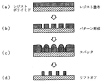
図3は、リフトオフ法を用いてポリイミド箔上に作製したひずみゲージの作製プロセスを示したものである。
先ず、ポリイミド箔上にレジストを塗布する(図3(a))。
次に、パターニングを行い、パターン形成する(図3(b))。
その後、Cu−Cr合金ターゲットを用い、スパッタ法によりCu−Cr合金膜をレジスト上に一様に形成する(図3(c))。
続いて、アセトン中でレジストと不用なCu−Cr合金膜を除去し、目的のパターンを得る(図3(d))。
なお、合金膜をレジスト上に形成する手段としては、スパッタ法に限らず、蒸着法等でも良く、その際の材料としてはNi−Cr等、ひずみにより抵抗が変化する抵抗材料であれば良い。
Next, an example of the above-described strain gauge pattern creation process will be described.
FIG. 3 shows a process for producing a strain gauge produced on a polyimide foil by using the lift-off method.
First, a resist is applied on the polyimide foil (FIG. 3A).
Next, patterning is performed to form a pattern (FIG. 3B).
Thereafter, using a Cu—Cr alloy target, a Cu—Cr alloy film is uniformly formed on the resist by sputtering (FIG. 3C).
Subsequently, the resist and unnecessary Cu—Cr alloy film are removed in acetone to obtain a target pattern (FIG. 3D).
The means for forming the alloy film on the resist is not limited to the sputtering method, but may be a vapor deposition method or the like. The material at that time may be a resistance material whose resistance changes due to strain, such as Ni—Cr.
図4は、ポリイミド箔上に作製した一体型ひずみゲージを示したものである。
この例では、ポリイミド箔上にパターンを形成したが、ポリイミド箔に限らず他のポリマー、SiO2膜等、絶縁膜であれば良い。また、ひずみゲージのパターンが形成できる手法であれば、リソグラフィー以外、印刷法でも良い。さらに、弾性薄板6上に絶縁膜を形成し、その上にひずみゲージパターンを作製し、弾性薄板−絶縁膜−ひずみゲージを一体としても良い。
FIG. 4 shows an integrated strain gauge fabricated on a polyimide foil.
In this example, a pattern was formed on the polyimide foil, other polymer is not limited to polyimide foil, S i O 2 film, etc., may be any insulating film. Further, as long as it is a technique capable of forming a strain gauge pattern, a printing method other than lithography may be used. Furthermore, an insulating film may be formed on the elastic
先端部材4を経由して伝わった接触力によりひずみゲージ5の抵抗変化をホイートストンブリッジ及び動ひずみアンプを用いて電気信号に変換することにより3軸方向の力を検出する手法について、図5に基づいて説明する。
センターホール2を中心にしてその周囲に120°間隔で3つのひずみゲージパターンを設けた一体型のひずみゲージ5の各ゲージ自体は抵抗体であり、3次元抗力センサが対象物と接触することにより、ひずみゲージI〜IIIは変形し、各々のその抵抗の大きさは微小であるが変化する。この抵抗変化をブリッジボックスを通すことにより、差動電圧として得ることが可能となる。この差動電圧は微小であるため、動ひずみアンプを用いて増幅することが必要となり、得られる各電圧値を用いコンピュータによる計算処理を行うことにより、加重pおよび角度φ、θを求めることができる。
Based on FIG. 5, a method for detecting a force in three axial directions by converting a resistance change of the
Each gauge of the
図6及び図7は、接触状態の荷重p及び角度φ、θを求める際の角度φ、θの関係を示すものであり、図6は正面図、図7は平面図である。
今、図6及び図7に示すように、実験条件として対象面と3次元抗力センサ1は面接触とし、荷重Pは面接触の垂直方向から加わるように設置する。
対象面が3次元抗力センサ1に対してある角度で接触する場合はセンサを横から見たときの垂直線からの角度をφ、真上から見たときのゲージを基準とした角度をθと定義することで、対象面の接触位置を表すことが可能である。
以下に荷重p (N)、角度θ (deg)、及び角度φ(deg)をそれぞれ変化させて3次元抗力センサ1の出力を測定し、その特性を調べることとする。
3つのゲージから得られる出力電圧はそれぞれ120°に近い位相差を持った正弦波形で近似でき、荷重pとφは正弦波の振幅に比例していることが分かっている。 よって、各センサからの出力と対象物との接触荷重pと接触角度θおよびφの関係は、実験的に求めた補正値である、振幅係数Ai、位相αi、平均出力をBiの値を用いて以下のように表せる。
Yi=Aiφpcos(θ+αi)+Bip
i=1〜3
6 and 7 show the relationship between the loads p and the angles φ and θ when the loads p and the angles φ and θ are obtained, FIG. 6 is a front view, and FIG. 7 is a plan view.
Now, as shown in FIGS. 6 and 7, as an experimental condition, the target surface and the three-dimensional drag sensor 1 are in surface contact, and the load P is installed so as to be applied from the vertical direction of the surface contact.
When the target surface is in contact with the three-dimensional drag sensor 1 at an angle, the angle from the vertical line when the sensor is viewed from the side is φ, and the angle based on the gauge when viewed from directly above is θ. By defining, it is possible to represent the contact position of the target surface.
Hereinafter, the output p of the three-dimensional drag sensor 1 is measured by changing the load p (N), the angle θ (deg), and the angle φ (deg), and the characteristics thereof are examined.
The output voltages obtained from the three gauges can be approximated by sinusoidal waveforms each having a phase difference close to 120 °, and it is known that the loads p and φ are proportional to the amplitude of the sinusoidal wave. Therefore, the relationship between the output from each sensor and the contact load p between the object and the contact angles θ and φ is the experimentally obtained correction values, ie, the amplitude coefficient A i , the phase α i , and the average output of B i . It can be expressed as follows using the value.
Y i = A i φpcos (θ + α i ) + B i p
i = 1 to 3
上記の式を連立して解くことによりpと接触角度θおよびφを求めることができる。 なお、計算は以下の手順の通りである。
Q1=A3B1B2{B3(B2Y1−B1Y2)+B2(B1Y3−B3Y1)}
Q2=A1B2B3{B3(B2Y1−B1Y2)+B2(B1Y3−B3Y1)}
Q3=A2B1B3{B3(B2Y1−B1Y2)+B1(B3Y2−B2Y3)}
Q4=A3B1B2{B3(B2Y1−B1Y2)+B1(B3Y2−B2Y3)}
D=Q4cosα3−Q3cosα2−Q2cosα1+Q1cosα3
E=Q1sinα3−Q2sinα1−Q3sinα2+Q4sinα3
とすると、
Θ=arctan{Q4cosα3−Q3cosα2−Q2cosα1+Q1cosα3/Q1sinα3−Q2sinα1−Q3sinα2+Q4sinα3}
E<0のとき、 θ=Θ+180°
D<0、E>0のとき、 θ=Θ+360°
それ以外のとき、 θ=Θ
求めたθを用い、p、φを求めると、
p=A2Y1cos(θ+α2)−A1Y2cos(θ+α1)/A2B1cos(θ+α2)−A1B2cos(θ+α1)
φ=Y1−B1p/A1pcos(θ+α1)
By solving the above equations simultaneously, p and the contact angles θ and φ can be obtained. The calculation is as follows.
Q 1 = A 3 B 1 B 2 {B 3 (B 2 Y 1 -B 1 Y 2) + B 2 (B 1 Y 3 -B 3 Y 1)}
Q 2 = A 1 B 2 B 3 {B 3 (B 2 Y 1 -B 1 Y 2) + B 2 (B 1 Y 3 -B 3 Y 1)}
Q 3 = A 2 B 1 B 3 {B 3 (B 2 Y 1 -B 1 Y 2) + B 1 (B 3 Y 2 -B 2 Y 3)}
Q 4 = A 3 B 1 B 2 {B 3 (B 2 Y 1 -B 1 Y 2) + B 1 (B 3 Y 2 -B 2 Y 3)}
D = Q 4 cos α 3 -Q 3 cos α 2 -Q 2 cos α 1 + Q 1 cos α 3
E = Q 1 sin α 3 −Q 2 sin α 1 −Q 3 sin α 2 + Q 4 sin α 3
Then,
Θ = arctan {Q 4 cos α 3 −Q 3 cos α 2 −Q 2 cos α 1 + Q 1 cos α 3 / Q 1 sin α 3 −Q 2 sin α 1 −Q 3 sin α 2 + Q 4 sin α 3 }
When E <0, θ = Θ + 180 °
When D <0, E> 0, θ = Θ + 360 °
Otherwise, θ = Θ
Using the obtained θ, p and φ are obtained,
p = A 2 Y 1 cos (θ + α 2 ) -A 1 Y 2 cos (θ + α 1 ) / A 2 B 1 cos (θ + α 2 ) -A 1 B 2 cos (θ + α 1 )
φ = Y 1 −B 1 p / A 1 pcos (θ + α 1 )
以上のようにセンサ出力より連立方程式を解くことにより、接触条件p、θおよびφを求めることが可能である。
そこで図6及びず7に示した方法で精度確認実験を行なった。実験方法は上記の特性測定と同様に行い、センサ出力から実験設定値を上記式から求め、設定値との誤差を求めた。得られた結果を表1に示す。結果より、誤差を伴うものの全てのセンサで荷重、角度の情報を特定することが可能であることが確認された。

Therefore, an accuracy confirmation experiment was performed by the method shown in FIGS. The experiment method was performed in the same manner as the above characteristic measurement, and an experimental set value was obtained from the sensor output from the above formula, and an error from the set value was obtained. The results obtained are shown in Table 1. From the results, it was confirmed that the load and angle information can be specified by all the sensors with an error.
1 3次元抗力センサ
2 センターホール
3 基体
4 先端部材
5 ひずみゲージ
6 弾性薄板
7 弾性薄板
8 小円形弾性薄板
DESCRIPTION OF SYMBOLS 1
Claims (1)
Priority Applications (1)
| Application Number | Priority Date | Filing Date | Title |
|---|---|---|---|
| JP2004245544A JP4350004B2 (en) | 2004-08-25 | 2004-08-25 | 3D drag sensor |
Applications Claiming Priority (1)
| Application Number | Priority Date | Filing Date | Title |
|---|---|---|---|
| JP2004245544A JP4350004B2 (en) | 2004-08-25 | 2004-08-25 | 3D drag sensor |
Publications (2)
| Publication Number | Publication Date |
|---|---|
| JP2006064465A JP2006064465A (en) | 2006-03-09 |
| JP4350004B2 true JP4350004B2 (en) | 2009-10-21 |
Family
ID=36111084
Family Applications (1)
| Application Number | Title | Priority Date | Filing Date |
|---|---|---|---|
| JP2004245544A Expired - Fee Related JP4350004B2 (en) | 2004-08-25 | 2004-08-25 | 3D drag sensor |
Country Status (1)
| Country | Link |
|---|---|
| JP (1) | JP4350004B2 (en) |
Cited By (1)
| Publication number | Priority date | Publication date | Assignee | Title |
|---|---|---|---|---|
| KR20150135194A (en) * | 2013-03-27 | 2015-12-02 | 세미텍 가부시키가이샤 | Contact force sensor and production method for same |
Families Citing this family (29)
| Publication number | Priority date | Publication date | Assignee | Title |
|---|---|---|---|---|
| JP4878513B2 (en) * | 2006-03-27 | 2012-02-15 | 国立大学法人 名古屋工業大学 | Apparatus and method for measuring compressive force of flexible linear body |
| DE102006030407A1 (en) | 2006-06-29 | 2008-01-03 | Werthschützky, Roland, Prof. Dr.-Ing. | Force sensor with asymmetric basic body for detecting at least one force component |
| DE102006031635A1 (en) | 2006-07-06 | 2008-01-17 | Werthschützky, Roland, Prof. Dr.-Ing. | Minaturisable force sensor for detecting a force vector |
| JP4878526B2 (en) * | 2006-09-05 | 2012-02-15 | 国立大学法人 名古屋工業大学 | Apparatus for measuring compressive force of flexible linear body |
| US8357152B2 (en) | 2007-10-08 | 2013-01-22 | Biosense Webster (Israel), Ltd. | Catheter with pressure sensing |
| US8535308B2 (en) | 2007-10-08 | 2013-09-17 | Biosense Webster (Israel), Ltd. | High-sensitivity pressure-sensing probe |
| US8437832B2 (en) | 2008-06-06 | 2013-05-07 | Biosense Webster, Inc. | Catheter with bendable tip |
| US9101734B2 (en) | 2008-09-09 | 2015-08-11 | Biosense Webster, Inc. | Force-sensing catheter with bonded center strut |
| US9326700B2 (en) | 2008-12-23 | 2016-05-03 | Biosense Webster (Israel) Ltd. | Catheter display showing tip angle and pressure |
| US8475450B2 (en) | 2008-12-30 | 2013-07-02 | Biosense Webster, Inc. | Dual-purpose lasso catheter with irrigation |
| US8600472B2 (en) | 2008-12-30 | 2013-12-03 | Biosense Webster (Israel), Ltd. | Dual-purpose lasso catheter with irrigation using circumferentially arranged ring bump electrodes |
| US10688278B2 (en) | 2009-11-30 | 2020-06-23 | Biosense Webster (Israel), Ltd. | Catheter with pressure measuring tip |
| US8920415B2 (en) | 2009-12-16 | 2014-12-30 | Biosense Webster (Israel) Ltd. | Catheter with helical electrode |
| US8521462B2 (en) | 2009-12-23 | 2013-08-27 | Biosense Webster (Israel), Ltd. | Calibration system for a pressure-sensitive catheter |
| US8529476B2 (en) | 2009-12-28 | 2013-09-10 | Biosense Webster (Israel), Ltd. | Catheter with strain gauge sensor |
| US8608735B2 (en) | 2009-12-30 | 2013-12-17 | Biosense Webster (Israel) Ltd. | Catheter with arcuate end section |
| US8374670B2 (en) | 2010-01-22 | 2013-02-12 | Biosense Webster, Inc. | Catheter having a force sensing distal tip |
| US8798952B2 (en) | 2010-06-10 | 2014-08-05 | Biosense Webster (Israel) Ltd. | Weight-based calibration system for a pressure sensitive catheter |
| US8226580B2 (en) | 2010-06-30 | 2012-07-24 | Biosense Webster (Israel), Ltd. | Pressure sensing for a multi-arm catheter |
| US8380276B2 (en) | 2010-08-16 | 2013-02-19 | Biosense Webster, Inc. | Catheter with thin film pressure sensing distal tip |
| US8731859B2 (en) | 2010-10-07 | 2014-05-20 | Biosense Webster (Israel) Ltd. | Calibration system for a force-sensing catheter |
| US8979772B2 (en) | 2010-11-03 | 2015-03-17 | Biosense Webster (Israel), Ltd. | Zero-drift detection and correction in contact force measurements |
| US9220433B2 (en) | 2011-06-30 | 2015-12-29 | Biosense Webster (Israel), Ltd. | Catheter with variable arcuate distal section |
| US9662169B2 (en) | 2011-07-30 | 2017-05-30 | Biosense Webster (Israel) Ltd. | Catheter with flow balancing valve |
| US9687289B2 (en) | 2012-01-04 | 2017-06-27 | Biosense Webster (Israel) Ltd. | Contact assessment based on phase measurement |
| KR101971945B1 (en) | 2012-07-06 | 2019-04-25 | 삼성전자주식회사 | Apparatus and method for sensing tactile |
| EP3411113B1 (en) | 2016-02-04 | 2019-11-27 | Cardiac Pacemakers, Inc. | Delivery system with force sensor for leadless cardiac device |
| US20210267709A1 (en) * | 2018-06-22 | 2021-09-02 | Universität Basel | Force sensing device, medical endodevice and process of using such endodevice |
| IT202000017662A1 (en) * | 2020-07-21 | 2022-01-21 | Favero Electronics S R L | PEDAL FOR BICYCLES AND RELATED METHOD OF REALIZATION |
-
2004
- 2004-08-25 JP JP2004245544A patent/JP4350004B2/en not_active Expired - Fee Related
Cited By (2)
| Publication number | Priority date | Publication date | Assignee | Title |
|---|---|---|---|---|
| KR20150135194A (en) * | 2013-03-27 | 2015-12-02 | 세미텍 가부시키가이샤 | Contact force sensor and production method for same |
| KR102185937B1 (en) | 2013-03-27 | 2020-12-02 | 세미텍 가부시키가이샤 | Contact force sensor |
Also Published As
| Publication number | Publication date |
|---|---|
| JP2006064465A (en) | 2006-03-09 |
Similar Documents
| Publication | Publication Date | Title |
|---|---|---|
| JP4350004B2 (en) | 3D drag sensor | |
| US8021361B2 (en) | Systems and methods for electrode contact assessment | |
| US9060713B2 (en) | Sensing tissue properties | |
| Polygerinos et al. | Triaxial catheter-tip force sensor for MRI-guided cardiac procedures | |
| Saccomandi et al. | Microfabricated tactile sensors for biomedical applications: a review | |
| DK2401980T3 (en) | Pressure sensing a multi-arm catheter | |
| JP5054103B2 (en) | Force sensor for detecting force vector | |
| US9164009B2 (en) | Miniaturized pressure sensor | |
| Li et al. | Disposable FBG-based tridirectional force/torque sensor for aspiration instruments in neurosurgery | |
| US20210186638A1 (en) | Surgical robot system and surgical instrument thereof | |
| Li et al. | Reaction force mapping by 3-axis tactile sensing with arbitrary angles for tissue hard-inclusion localization | |
| Koch et al. | Skin attachable flexible sensor array for respiratory monitoring | |
| US8596111B2 (en) | System for sensing and displaying softness and force | |
| Li et al. | Mechanical imaging of soft tissues with a highly compliant tactile sensing array | |
| Dai et al. | Grasper integrated tri-axial force sensor system for robotic minimally invasive surgery | |
| US20160213280A1 (en) | Medical device for contact sensing | |
| Sattayasoonthorn et al. | On the feasibility of a liquid crystal polymer pressure sensor for intracranial pressure measurement | |
| Padmanabhan et al. | Force sensing technologies for catheter ablation procedures | |
| Koch et al. | Stretchable sensor array for respiratory monitoring | |
| EP1750578A1 (en) | Blood pressure monitoring device and methods for making and for using such a device | |
| Srivastava et al. | Design of an ultra thin strain sensor using superelastic nitinol for applications in minimally invasive surgery | |
| Arabagi et al. | Simultaneous soft sensing of tissue contact angle and force for millimeter-scale medical robots | |
| WO2019179795A1 (en) | Medical device comprising sensor array and system for measurements | |
| CN113483816B (en) | Shape-position-force composite sensing unit and measuring method thereof | |
| Yang et al. | Modelling and characterization of an instrumented medical needle in sight of new microsensor design for its insertion guidance |
Legal Events
| Date | Code | Title | Description |
|---|---|---|---|
| A621 | Written request for application examination |
Free format text: JAPANESE INTERMEDIATE CODE: A621 Effective date: 20061013 |
|
| A977 | Report on retrieval |
Free format text: JAPANESE INTERMEDIATE CODE: A971007 Effective date: 20090428 |
|
| A131 | Notification of reasons for refusal |
Free format text: JAPANESE INTERMEDIATE CODE: A131 Effective date: 20090512 |
|
| A521 | Written amendment |
Free format text: JAPANESE INTERMEDIATE CODE: A523 Effective date: 20090626 |
|
| TRDD | Decision of grant or rejection written | ||
| A01 | Written decision to grant a patent or to grant a registration (utility model) |
Free format text: JAPANESE INTERMEDIATE CODE: A01 Effective date: 20090721 |
|
| A01 | Written decision to grant a patent or to grant a registration (utility model) |
Free format text: JAPANESE INTERMEDIATE CODE: A01 |
|
| A61 | First payment of annual fees (during grant procedure) |
Free format text: JAPANESE INTERMEDIATE CODE: A61 Effective date: 20090721 |
|
| FPAY | Renewal fee payment (event date is renewal date of database) |
Free format text: PAYMENT UNTIL: 20120731 Year of fee payment: 3 |
|
| R150 | Certificate of patent or registration of utility model |
Free format text: JAPANESE INTERMEDIATE CODE: R150 |
|
| LAPS | Cancellation because of no payment of annual fees |