JP4348947B2 - Information output apparatus and information output method - Google Patents
Information output apparatus and information output method Download PDFInfo
- Publication number
- JP4348947B2 JP4348947B2 JP2003003853A JP2003003853A JP4348947B2 JP 4348947 B2 JP4348947 B2 JP 4348947B2 JP 2003003853 A JP2003003853 A JP 2003003853A JP 2003003853 A JP2003003853 A JP 2003003853A JP 4348947 B2 JP4348947 B2 JP 4348947B2
- Authority
- JP
- Japan
- Prior art keywords
- output
- information
- circuit
- circuits
- output circuits
- Prior art date
- Legal status (The legal status is an assumption and is not a legal conclusion. Google has not performed a legal analysis and makes no representation as to the accuracy of the status listed.)
- Expired - Lifetime
Links
Images


Description
【0001】
【発明の属する技術分野】
本発明は、映像、音声などのディジタル情報を出力する情報出力装置および情報出力方法に関する。
【0002】
【従来の技術】
映像、音声などの情報をディジタル情報として扱うと、情報の伝送過程や記録再生過程での品質劣化がない、もしくはごく少ない長所がある。しかし、情報の良質なコピーが、著作権者の預かり知らぬところで多数作成されて出回り、またコピーが繰返された場合、その著作権者に利益が還元されない問題がある。
【0003】
特許文献1には、情報に2ビットのコピー制御情報を付す方法が開示されている。これは著作権者や情報作成者の意志により、「コピー禁止」(Copy Never)、「コピー認可」(Copy Free)、「一世代のみコピー認可」(Copy One Generation)の3つのうちいずれかを選択することで、記録装置の動作を制御するものである。記録装置は、「コピー禁止」ならば記録動作をせず、「コピー認可」なら記録動作を行う。「一世代のみコピー認可」ならば、この制御情報を「これ以上のコピーを認めない」(No More Copies)という情報に書換えた上で、記録動作を行う。
【0004】
【特許文献1】
米国特許第5896454号明細書
【0005】
【発明が解決しようとする課題】
上記従来の技術に開示される事項は、与えられた情報を記録装置に供給した場合の、記録装置側の動作を規定するものである。しかし、「一世代のみコピー認可」(Copy One Generation)とされた情報の扱いには、次のような問題がある。
【0006】
「一回のみコピー認可」(Copy Once)ではなく、「一世代のみコピー認可」(Copy One Generation)とする理由は、接続されている記録装置の数、あるいはコピーの数を制限する有効な方法がなかったためである。従って、記録装置の数さえ揃えれば無数の記録媒体に記録することも可能となり、実質的には「コピー認可」(Copy Free)と変わらなくなり、著作権者の利益が損なわれてしまう。この問題に関しては、上記した文献では言及されていない。
【0007】
本発明の目的は、上記した問題に鑑み、著作権者の利益を保護する方法と装置を提供することにある。
【0008】
【課題を解決するための手段】
上記目的は、その一例として特許請求の範囲に記載の構成により達成できる。
【0009】
【発明の実施の形態】
以下、本発明の実施形態を、図面を用いて詳細に説明する。まず本発明を適用するシステム全体から述べる。
【0010】
図1は、本発明の情報出力装置が用いられるシステム全体の第1の実施形態を示すブロック図である。放送局などの情報提供局1から中継局2を介して放送された情報を受信装置3で受信し、第1の記録再生装置4、第2の記録再生装置6A、第3の記録再生装置6Bで記録再生し、ディスプレイ5で視聴するものである。この場合、受信装置3が本発明でいう情報出力装置に相当し、記録再生装置6A、6Bが外部機器に相当する。
【0011】
放送局など情報提供局1は、例えば放送用衛星などの中継局2を介して、情報によって変調された信号電波として伝送する。この他に、ケーブルによる伝送、電話線による伝送、地上波放送による伝送などを用いても良い。受信側の受信装置3は、信号を受信し復調した後、必要に応じ第1の記録再生装置4、第2の記録再生装置6A、第3の記録再生装置6Bへ記録する。また、ディスプレイ5により、受信した情報内容を直接に、または上記した第1〜第3の記録再生装置4、6A、6Bで再生された情報を視聴する。
【0012】
第1の記録再生装置4は、ここでは受信装置3に内蔵されるディジタル記録方式によるものとする。その記録媒体には、例えばハードディスクが利用できる。受信装置に内蔵する記録再生装置は、情報の保存期間は比較的短いので、取外しのできない媒体で良い。第2の記録再生装置6Aと第3の記録再生装置6Bは、ここでは受信装置3に外付けされる。記録媒体は、ハードディスクの他、磁気テープ、光ディスクのように取外しのできる媒体でも良い。
【0013】
放送された情報に付されたコピー制御情報が、「コピー認可」であれば、第1〜第3の記録再生装置4、6A、6Bのいずれにも記録することができるが、コピー制御情報が、「コピー禁止」または「一世代のみコピー認可」であれば、後述するように記録が制限される。
【0014】
図1の例では3台の記録再生装置を有するが、これに限定されない。すなわち装置の台数、または内蔵されるか外付けであるかに関わらず、本発明は適用可能である。また本発明は、受信した情報を記録再生するシステムにのみ適用されるものではない。予め情報を記録したパッケージソフトを再生する場合はもちろん、単に現在放送中の情報を受信してディスプレイ5に出力する場合、またPC(Personal Computer)のハードディスクなどから情報を再生し、グラフィックボード等を介して装置の外部へ出力する場合にも適用できる。
【0015】
情報が予め記録された取外し可能な記録媒体、例えばパッケージソフトが提供される時は、これを取付けた、例えば第2の記録再生装置6Aでの再生動作以降が行われる。この場合は、情報提供局1と中継局2を除いた状態となるが、やはり本発明を適用できる。
【0016】
装置間の情報の授受はディジタル信号で行われることが多いが、例えば受信装置3とディスプレイ5の間は、アナログ信号で接続することもある。輝度と2つの色差信号で接続することもあれば、PCのようにRGB信号で接続することもある。
【0017】
図2は、図1における情報提供局1の構成例を示すブロック図である。カメラ、記録再生装置などから成るソース発生部11で発生した映像・音声などの情報は、より少ない占有帯域で伝送できるよう、エンコード回路12でMPEG方式等によりデータ量の圧縮が施される。コピーの制限等の保護が必要な場合は、スクランブル回路13で伝送暗号化される。変調回路14で伝送するのに適した信号に変調された後、送信アンテナ15から、例えば放送用衛星などの中継局2に向けて電波として発射される。この際、管理情報付与回路16では、前記したコピー制御情報などを付加する。また入力端子17には、例えばビデオオンデマンドにおける受信側からのリクエスト情報が電話回線などを介して入力され、これに応えて送出する情報を決定する。
【0018】
なお、送信する電波信号には、複数の情報が、時分割、スペクトル拡散などの方法で多重されることが多い。この場合には、ソース発生部11とエンコード回路12の系統が複数個あり、エンコード回路12とスクランブル回路13との間に、複数の情報を多重するマルチプレクス回路が置かれる。
【0019】
図3は、図1のシステムにおける受信装置3の構成例を示すブロック図である。図中の実線は受信した映像音声など主となる情報の流れを、また破線は各構成要素間の制御信号情報の流れを示す。第1の記録再生装置4は、受信装置3に内蔵される場合を示す。
【0020】
まず、本実施例の構成を、実線で示した映像音声などの主情報の流れに沿って説明する。RF/IF変換回路301には、例えば放送用衛星などの中継局からの電波が入力される。ここで、RF帯域の電波はIF帯域(Intermediate Frequency)に周波数変換され、また受信チャンネルに依存しない一定の帯域の信号となり、復調回路302で伝送のために施された変調操作が復調される。さらに誤り訂正回路303で、伝送途中で発生した符号の誤りが検出さらには訂正された後、デスクランブル回路304で伝送暗号の解除を行う。その後、第1および第2のデマルチプレクス回路305、307へ送られる。デマルチプレクス回路305、307は、1つのチャンネルに多重された複数の情報から所望の情報だけを分離する。2つのデマルチプレクス回路を設ける理由は、いわゆる裏番組記録を可能にするのみならず、第1のデマルチプレクス回路305で、記録しない情報を除去、及び記録のための情報を付加するためである。例えば、天気予報、番組の放送予定など、記録する必要のないものはここで除去する。
【0021】
第1のデマルチプレクス回路305の出力は、第1の記録再生装置4へ与えられるとともに、入出力回路315A、315Bへも与えられる。入出力回路315A、315Bは、入出力端子306A、306Bを介して、それぞれ第2の記録再生装置6A、第3の記録再生装置6Bが接続される。入出力回路315A、315Bは、例えば双方向の入出力インターフェースであって、第2、第3の記録再生装置6A、6Bとの間で、記録再生する情報などを例えばディジタルデータで授受する。一般にはIEEE1394規格による接続が多く用いられる。またPCで多用されるUSB(Universal Serial Bus)接続であっても良いし、無線LAN(Local Area Network)などを用いて無線で接続しても良い。また、入出力回路315A、315Bの数はこれに限らずさらに多数個設けても良く、あるいは仕様の異なる複数の入出力インターフェースを使用しても良い。
【0022】
第1〜第3の記録再生装置4、6A、6Bにおいては、記録する情報に付されたコピー制御情報に従って記録動作を行う。コピー制御情報が、「コピー禁止」(Copy Never)ないし「これ以上のコピーを認めない」(No More Copies)を示すならば、記録を行わない。「一世代のみコピー認可」(Copy One Generation)であるならば、これを「これ以上のコピーを認めない」(No More Copies)と書替えたうえで記録を行う。「コピー認可」(Copy Free)であるならば、そのまま記録を行う。なお特殊な場合として、Copy Neverでありながら再生利用する期間に制限を付けて一時記録する場合や、No More Copiesでありながら元の情報源を再生不能にすることを条件に情報を移動する場合などの記録動作を認めてもよい。
【0023】
先の第2のデマルチプレクス回路307には、デスクランブル回路304から送られた情報、第1の記録再生装置4で再生された情報、あるいは入出力回路315A、315Bを経由して第2、第3の記録再生装置6A、6Bで再生された情報が入力されており、これらから所望の情報が選択・分離される。次のデコード回路308では、伝送前に施されたMPEG方式等によるデータ圧縮に対する伸張処理がなされ、出力端子309、310を介して外部の装置へ送られる。出力端子309、310はディジタル出力、アナログ出力いずれの場合もあり、また前者をディジタル出力、後者をアナログ出力と使い分けることもできる。出力端子は1個としても良い。
【0024】
次に、図3における構成を破線で示した制御信号に沿って述べる。制御回路311は、上記したRF/IF変換回路301から第1、第2のデマルチプレクス回路305、307、デコード回路308、さらに入出力回路315A、315Bに至る各構成要素との間で制御信号の授受を行い、受信装置3の全体が所望の動作を行うように制御する。情報管理回路312は、制御回路311に対し制御を行う時ための管理データを要求に応じて供給する。例えば、ここには受信契約の情報が管理されている。ユーザが視聴したいチャンネルを指定した時、この指定は入力端子314から入力され、コマンド入力回路313を介して制御回路311に送られる。制御回路311は情報管理回路312に、受信契約情報を要求する。ユーザが指定したチャンネルと契約があると判断した場合、上記した各構成要素に制御信号を送り、該当チャンネルの受信動作を指示するなどの制御動作を行う。
【0025】
また、第1の記録再生装置4が受信装置3に内蔵されている場合には、入力端子314から入力されたユーザの指示に応じて記録再生の動作を行う。このため、コマンド入力回路313の出力が供給されている。この制御信号は、制御回路311から供給されるようにしても良い。
【0026】
次に、受信した情報に付加されている、あるいは入出力回路からの出力時に付加するコピー制御情報について説明する。コピー制御情報は、例えば、表1のような3ビットの情報を用いる。
【0027】
【表1】

CCIは、2ビットの情報で、「00」の時は「コピー認可」(Copy Free)を表し、「10」の時は、「一世代のみコピー認可」(Copy One Generation)を表し、「01」の時は、「これ以上のコピーを認めない」(No More Copies)、すなわち一世代のみコピーできる情報がコピーされたものであることを表し、「11」の時は「コピー禁止」(Copy Never)を表す。なお、No More Copiesは、放送などの送信時には用いられない。CCIが「00」以外の時は、出力時に暗号化して伝送することにより、不正なコピーがなされた時に情報を保護する。EPNは、1ビットの情報で、この情報が「0」の時は、コピーの制限はないが、暗号化して伝送することを表す。これにより、正規の記録機器でのコピー以外の不正使用から情報を保護する。
【0029】
次に、本発明の特徴であるコピー数の制限について説明する。コピー数を制限するためには、全ての入出力端子に接続される機器の数を制限すればよい。すなわち、入出力回路315Aに接続されている機器の数と、入出力回路315Bの接続されている機器の数の合計の数Nを制御回路311で管理し、その数が所定の制限数Nm(例えばNm=62)以下になるように制限する。
【0030】
図4は、入出力回路315Aあるいは315Bにおける機器の接続のフローチャートを示す。接続しようとする機器から接続要求(S101)があると、入出力回路315A、315Bは制御回路311に対し現在接続されている機器の数Nを問い合わせる(S102)。そして、Nが制限数Nm未満であれば(S103)、その機器と認証を行う(S104)。認証は、例えば、決められた情報を相手機器に送り、それに対する応答によって正規に機器であるかどうかを判定する(S105)。認証が成功すれば、相手機器が正規の機器であると判断し、暗号化の鍵を相手機器に渡し(S106)、接続を完了すると同時に、接続を行ったことを制御回路311に通知し、制御回路311で管理している接続数Nを更新する(S107)。NがNm未満でないとき(S103)、または、認証が成功しない場合には(S105)、暗号化の鍵を相手機器に渡さないで接続を破棄する(S108)。これにより、接続の認められていない機器が仮に情報を受け取っても、解読鍵を有していないため暗号化された情報の復号ができない。
【0031】
なお、接続要求(S101)は、認証の要求であってもよく、この場合には、認証されている機器の数Nを管理することになる。また、暗号化の鍵を渡す(S106)のではなく共有鍵を生成するための情報を渡してもよい。
【0032】
通常、認証の処理は入出力回路で行われる。したがって、ひとつの入出力回路のみの場合はその入出力回路で認証を行うと共に接続数の管理を行えばよいが、複数の入出力回路がある場合には、個々の入出力回路における接続数は管理できるが、全体の接続数を管理することができない。このような場合でも、制御回路311において接続数を管理することにより全ての入出力回路に接続されている機器の数を管理することができる。
【0033】
このように、複数の入出力回路を有する場合でも接続される機器の数を制限することによってコピー数を制限することができる。なお、複数の入出力回路は、異なる仕様のインターフェースであってもよいし、もちろん、出力専用のインターフェースであってもよい。また、認証の処理を含めて制御回路311を行ってもよい。
【0034】
接続数Nの管理は、コピー制御情報で示される保護対象となる情報を出力する時にのみ行えばよい。情報が保護を必要とする全ての場合に行ってもよいが、コピー数の制限を目的とするのであれば、例えばCopy One Generationの情報を出力する時にのみ行ってもよい。また、全ての入出力回路に接続されている全ての機器について行ってもよいが、保護対象の情報を出力する入出力回路のみ、あるいは記録可能機器のみについて管理すれば、より正確に管理することができる。なお、複数種類の情報を出力する場合には、それぞれの情報毎に独立して管理すればよい。
【0035】
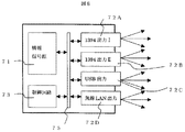
図5は、本発明の情報出力装置の第2の実施形態を示すブロック図である。情報信号源71は情報受信装置あるいは情報再生装置等からなり、情報を入出力回路72A〜72Dにて外部機器へ送出する。ここに一例として、入出力回路72A、72BはIEEE1394規格、入出力回路72CはUSB規格、入出力回路72Dは無線ネットワークによるインターフェースとした。制御回路73は、図3の制御回路311と同様である。このように、複数の異なる仕様の入出力回路を有する場合でも、図3の場合と同様に、制御回路73で全体の接続される機器の数を制限することによってコピー数を制限することができる。
【0036】
なお、入出力回路72Aと72Bは同一のインターフェースであるが、識別IDの異なる回路から出力されるような場合は独立した出力となり、接続等の処理はそれぞれの入出力回路で行われる。また、同一のインターフェースであるが、異なる伝送方式(伝送プロトコル)によって伝送する場合においても、それぞれの伝送方式で独立して制御が行われている時には、全体の接続される機器の数を制御回路73で管理すればよい。
【0037】
図6は、本発明の情報出力装置の第3の実施形態を示すブロック図である。この実施形態は、異なるバスの間を中継するバスブリッジ74が介在する場合である。この場合には、バスブリッジ74を介して接続されている機器数も考慮する必要がある。なお、バスブリッジ74は、同一の仕様のバスを中継するものであってもよいし、異なる仕様のバスを中継するものであってもよい。
【0038】
図7は、図6の実施形態のようなバスブリッジ74が介在する場合の、機器の接続のフローチャートを示す。接続しようとする機器から接続要求があると(S111)、入出力回路72A〜72Dは制御回路73に対し現在接続されている機器の数Nを問い合わせる(S112)。次に、接続しようとする機器の認証を行う(S113)。なお、この時に、図4の場合(S103)と同様にNが制限数Nm未満であるかどうかの確認を行ってもよい。認証が成功すれば、相手機器が正規の機器であると判断し(S114)、次に、相手機器がバスブリッジであるかどうかを確認する(S115)。バスブリッジでない場合は(S120)、Nが制限数Nm未満であれば暗号化の鍵を相手機器に渡し(S121)、接続を完了すると同時に、接続を行ったことを制御回路73に通知し、制御回路73で管理している接続数Nを更新する(S122)。相手機器がバスブリッジである場合には、バスブリッジを介して接続されている数Nbをバスブリッジより取得する(S116)。そして、N+NbがNm以下であれば(S117)暗号化の鍵を相手機器に渡し(S118)、接続を完了すると同時に、接続を行ったことを制御回路73に通知し、制御回路73で管理している接続数NをN+Nbに更新する。N+NbがNmを超えている場合は(S120)接続を破棄する(S123)。なお、Nmを超えない範囲にバスブリッジを介した接続を制限して接続を行ってもよい。
【0039】
図8は、本発明の情報出力装置の第4の実施形態を示すブロック図である。ここでは、例えばPC機器のような情報信号源71、制御回路73および入出力回路72A〜72Dが内部バス75を介して接続されており、取り外し可能とした場合である。ここに内部バス75は、1つのバスに全ての回路を接続してもよいし、複数の内部バスを用いて、例えば情報信号源71は第1のバスを介して制御回路73に接続し、入出力回路72A〜72Dは第2のバスを介して制御回路73に接続してもよい。
【0040】
この実施形態では、まず、装着されている入出力回路72A〜72Dが正規のものであるか、すなわち接続数制限に対応しているものであるかどうかを確認する必要がある。従って、制御回路73は、装着されている入出力回路72A〜72Dとの認証を行い、認証が成功した入出力回路に対して、情報信号源71から情報を暗号化して送る。これにより、正規の入出力回路以外の入出力回路を介して情報が出力されてしまうことを防ぐことができる。また、認証を行わなくても、正規の入出力回路と情報信号源71で共通の鍵を共有しておくようにしてもよい。接続数の制限は、図4あるいは図7と同様の手順で行えばよい。
【0041】
図9は、本発明の情報出力装置の第5の実施形態を示すブロック図である。80A〜80Dは暗号化の鍵を管理する鍵管理部、82は接続数Nを管理する接続数管理部である。接続しようとする機器から接続要求あるいは認証要求があると、入出力回路72A、72B、72Cまたは72Dは制御回路73に対し現在接続あるいは認証されている機器の数Nを問い合わせる。そして、Nが制限数Nm未満であれば、その機器と認証を行い、認証が成功すれば、相手機器が正規の機器であると判断し、鍵管理部80A、80B、80Cまたは80Dで管理されている暗号化の鍵あるいは共有鍵を生成するための情報を相手機器に渡し、接続を完了すると同時に、接続を行ったことを制御回路73に通知し、制御回路73では管理している接続数Nを更新する。このように、鍵管理部80A、80B、80Cまたは80Dでは、それぞれの入出力回路で暗号化する鍵を管理し、制御回路73において接続数Nを管理することにより、それぞれの入出力回路で異なる暗号化鍵を用いる場合、さらには、異なる暗号化方式あるいは認証方式を用いる場合においても接続数の管理を行うことができる。
【0042】
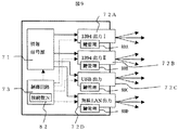
図10は、本発明の情報出力装置の第6の実施形態を示すブロック図である。81は暗号化の鍵を管理する鍵管理部である。接続しようとする機器から接続要求あるいは認証要求があると、入出力回路72A、72B、72Cまたは72Dは制御回路73に対して認証を要求する。制御回路73では、現在接続あるいは認証されている機器の数Nを確認し、Nが制限数Nm未満であれば、その機器と認証を行い、認証が成功すれば、相手機器が正規の機器であると判断し、鍵管理部81で管理されている暗号化の鍵あるいは共有鍵を生成するための情報を相手機器に渡し、接続を完了すると同時に、接続数Nを更新する。このように、制御回路73において暗号化鍵及び接続数Nを管理することにより、複数の入出力回路を有する場合でも、認証及び鍵管理を1つの回路で行うことができる。
【0043】
図11は、本発明の情報出力装置の第7の実施形態を示すブロック図である。83A、83Bは情報信号源71の情報、84A、84Bはそれぞれの情報に対する接続数NA、NBを管理する接続数管理部、85A、85Bはそれぞれの情報に対する暗号化鍵を管理する鍵管理部である。情報83A、83Bは、例えば、受信した異なるチャンネルの情報や受信した情報と再生装置から再生した情報等である。情報信号源71から情報A、情報Bのような複数種類の情報を出力する場合に、それぞれの情報毎に接続数を管理することにより、情報毎にコピー数を制限することができる。
【0044】
もちろん、複数種類の情報を出力する場合でも全体の接続数のみで管理してもよい。この場合には、必要以上に接続数が制限されることになるが、どの情報がどこに出力されているかを管理する必要がなく、管理のための処理を簡単にすることができる。これより、「一世代のみコピー認可」のようにコピーが制限される場合に、無数の記録媒体に無制限にコピーが行われるのを防止できる。
【0045】
【発明の効果】
以上述べたように本発明によれば、著作権者の利益を保護する装置及び方法を提供できる。
【図面の簡単な説明】
【図1】本発明の情報出力装置を適用するシステム全体の第1の実施形態を示すブロック図。
【図2】図1における情報提供局1の構成例を示すブロック図。
【図3】図1における受信装置3(情報出力装置)の構成例を示すブロック図。
【図4】第1の実施形態における機器の接続のフローチャートを示す図。
【図5】本発明の情報出力装置の第2の実施形態を示すブロック図。
【図6】本発明の情報出力装置の第3の実施形態を示すブロック図。
【図7】第3の実施形態における機器の接続のフローチャートを示す図。
【図8】本発明の情報出力装置の第4の実施形態を示すブロック図。
【図9】本発明の情報出力装置の第5の実施形態を示すブロック図。
【図10】本発明の情報出力装置の第6の実施形態を示すブロック図。
【図11】本発明の情報出力装置の第7の実施形態を示すブロック図。
【符号の説明】
1・・・・・情報提供局
2・・・・・中継局
3・・・・・受信装置(情報出力装置)
4・・・・・第1の記録再生装置
5・・・・・ディスプレイ
6A・・・・第2の記録再生装置
6B・・・・第3の記録再生装置
306A、306B、309、310・・・入出力端子
308・・・デコード回路
311、73・・・・制御回路
315A、315B、72A〜72D・・・・入出力回路
71・・・・情報信号源
74・・・・バスブリッジ
75・・・・内部バス
80A〜80D、81、85A、85B・・・・鍵管理部
82、84A、84B・・・・接続数管理部
83A、83B・・・・情報[0001]
BACKGROUND OF THE INVENTION
The present invention relates to an information output apparatus and an information output method for outputting digital information such as video and audio.
[0002]
[Prior art]
When information such as video and audio is handled as digital information, there is an advantage that there is no or very little quality degradation in the information transmission process and recording / reproduction process. However, when a large number of good-quality copies of information are made and made available at places unknown to the copyright holder, and the copy is repeated, there is a problem that the profit is not returned to the copyright holder.
[0003]
[0004]
[Patent Document 1]
US Pat. No. 5,896,454
[Problems to be solved by the invention]
The matter disclosed in the above prior art defines the operation on the recording apparatus side when the given information is supplied to the recording apparatus. However, there is the following problem in the handling of information that is "Copy one generation only" (Copy One Generation).
[0006]
The reason for "Copy One Generation" instead of "Copy Once" is an effective way to limit the number of connected recording devices or the number of copies. Because there was no. Therefore, if the number of recording devices is equal, recording can be performed on an infinite number of recording media, which is substantially the same as “copy authorization”, and the profits of the copyright holder are impaired. This problem is not mentioned in the above mentioned literature.
[0007]
An object of the present invention is to provide a method and apparatus in view of the problems described above, to protect the interests of the copyright owner.
[0008]
[Means for Solving the Problems]
The above object can be achieved by , for example, the configuration described in the claims .
[0009]
DETAILED DESCRIPTION OF THE INVENTION
Hereinafter, embodiments of the present invention will be described in detail with reference to the drawings. First, the entire system to which the present invention is applied will be described.
[0010]
FIG. 1 is a block diagram showing a first embodiment of the entire system in which the information output apparatus of the present invention is used. Information broadcast from an
[0011]
The
[0012]
Here, it is assumed that the first recording / reproducing
[0013]
If the copy control information attached to the broadcast information is “copy authorization”, it can be recorded in any of the first to third recording / reproducing
[0014]
Although the example of FIG. 1 has three recording / reproducing apparatuses, the present invention is not limited to this. That is, the present invention can be applied regardless of the number of devices or whether they are built-in or external. The present invention is not applied only to a system for recording / reproducing received information. Of course, when reproducing packaged software in which information is recorded in advance, simply receiving information currently being broadcast and outputting it to the
[0015]
When a removable recording medium in which information is recorded in advance, for example, package software, is provided, the reproduction operation and the like in the second recording / reproducing apparatus 6A to which the information is attached, for example, is performed. In this case, the
[0016]
Information is often exchanged between devices using digital signals. For example, the receiving
[0017]
FIG. 2 is a block diagram showing a configuration example of the
[0018]
In many cases, a plurality of pieces of information are multiplexed in a radio wave signal to be transmitted by a method such as time division or spread spectrum. In this case, there are a plurality of systems of the
[0019]
FIG. 3 is a block diagram illustrating a configuration example of the receiving
[0020]
First, the configuration of the present embodiment will be described along the flow of main information such as video and audio indicated by a solid line. For example, radio waves from a relay station such as a broadcasting satellite are input to the RF /
[0021]
The output of the
[0022]
In the first to third recording / reproducing
[0023]
The
[0024]
Next, the configuration in FIG. 3 will be described along control signals indicated by broken lines. The control circuit 311 controls signals between the RF /
[0025]
When the first recording / reproducing
[0026]
Next, copy control information added to received information or added at the time of output from an input / output circuit will be described. As the copy control information, for example, 3-bit information as shown in Table 1 is used.
[0027]
[Table 1]
The CCI is 2-bit information. When it is “00”, it represents “Copy Authorization” (Copy Free), and when it is “10”, it represents “Copy One Generation” (Copy One Generation). "No more copies" (No More Copies), that is, information that can be copied only for one generation is copied, and "11" is "Copy prohibited" (Copy Never). Note that “No More Copies” is not used when broadcasting or the like. When the CCI is other than “00”, the information is protected when an illegal copy is made by encrypting and transmitting at the time of output. EPN is 1-bit information. When this information is “0”, it indicates that there is no copy restriction, but it is encrypted and transmitted. This protects information from unauthorized use other than copying on legitimate recording devices.
[0029]
Next, the limitation on the number of copies, which is a feature of the present invention, will be described. In order to limit the number of copies, the number of devices connected to all input / output terminals may be limited. That is, the total number N of the number of devices connected to the input / output circuit 315A and the number of devices connected to the input / output circuit 315B is managed by the control circuit 311 and the number is a predetermined limit number Nm ( For example, it is limited so that Nm = 62) or less.
[0030]
FIG. 4 shows a flowchart of device connection in the input / output circuit 315A or 315B. When there is a connection request (S101) from the device to be connected, the input / output circuits 315A and 315B inquire the control circuit 311 about the number N of currently connected devices (S102). If N is less than the limit number Nm (S103), authentication with the device is performed (S104). In the authentication, for example, determined information is sent to the counterpart device, and it is determined whether or not the device is legitimate by a response to the information (S105). If the authentication is successful, it is determined that the partner device is a legitimate device, the encryption key is passed to the partner device (S106), the connection is completed, and at the same time, the control circuit 311 is notified that the connection has been made, The number N of connections managed by the control circuit 311 is updated (S107). When N is not less than Nm (S103), or when authentication is not successful (S105), the connection is discarded without passing the encryption key to the partner device (S108). Thus, even if a device that is not permitted to connect receives information, the encrypted information cannot be decrypted because the device does not have a decryption key.
[0031]
Note that the connection request (S101) may be an authentication request. In this case, the number N of devices that are authenticated is managed. Further, instead of passing the encryption key (S106), information for generating a shared key may be passed.
[0032]
Normally, the authentication process is performed by an input / output circuit. Therefore, in the case of only one input / output circuit, authentication may be performed by the input / output circuit and the number of connections may be managed. However, when there are a plurality of input / output circuits, the number of connections in each input / output circuit is as follows. Can manage, but cannot manage the total number of connections. Even in such a case, the number of devices connected to all the input / output circuits can be managed by managing the number of connections in the control circuit 311.
[0033]
As described above, even when a plurality of input / output circuits are provided, the number of copies can be limited by limiting the number of connected devices. Note that the plurality of input / output circuits may be interfaces having different specifications, or of course, may be interfaces dedicated to output. In addition, the control circuit 311 may be performed including authentication processing.
[0034]
The management of the number N of connections may be performed only when information to be protected indicated by the copy control information is output. This may be performed in all cases where the information needs protection, but may be performed only when outputting Copy One Generation information, for example, if the purpose is to limit the number of copies. This may be done for all devices connected to all input / output circuits. However, if only the input / output circuits that output the information to be protected or only the recordable devices are managed, management will be more accurate. Can do. In the case of outputting a plurality of types of information, each information may be managed independently.
[0035]
FIG. 5 is a block diagram showing a second embodiment of the information output apparatus of the present invention. The
[0036]
The input /
[0037]
FIG. 6 is a block diagram showing a third embodiment of the information output apparatus of the present invention. In this embodiment, a
[0038]
FIG. 7 shows a flowchart of connection of devices when a
[0039]
FIG. 8 is a block diagram showing a fourth embodiment of the information output apparatus of the present invention. In this case, for example, an
[0040]
In this embodiment, first, it is necessary to check whether or not the input /
[0041]
FIG. 9 is a block diagram showing a fifth embodiment of the information output apparatus of the present invention. 80A to 80D are key management units for managing encryption keys, and 82 is a connection number management unit for managing the number N of connections. When there is a connection request or authentication request from the device to be connected, the input /
[0042]
FIG. 10 is a block diagram showing a sixth embodiment of the information output apparatus of the present invention. Reference numeral 81 denotes a key management unit that manages encryption keys. When there is a connection request or an authentication request from a device to be connected, the input /
[0043]
FIG. 11 is a block diagram showing a seventh embodiment of the information output apparatus of the present invention. 83A and 83B are information of the
[0044]
Of course, even when a plurality of types of information are output, management may be performed only with the total number of connections. In this case, the number of connections is limited more than necessary, but it is not necessary to manage which information is output where, and the management process can be simplified. As a result, in the case where copying is restricted as in “one-generation copy authorization”, it is possible to prevent unlimited copying on an unlimited number of recording media.
[0045]
【The invention's effect】
As described above, according to the present invention, an apparatus and a method for protecting the interests of the copyright holder can be provided.
[Brief description of the drawings]
FIG. 1 is a block diagram showing a first embodiment of an entire system to which an information output apparatus of the present invention is applied.
2 is a block diagram showing a configuration example of an
3 is a block diagram illustrating a configuration example of a reception device 3 (information output device) in FIG. 1. FIG.
FIG. 4 is a diagram showing a flowchart of device connection in the first embodiment.
FIG. 5 is a block diagram showing a second embodiment of the information output apparatus of the present invention.
FIG. 6 is a block diagram showing a third embodiment of the information output apparatus of the present invention.
FIG. 7 is a diagram showing a flowchart of device connection in the third embodiment.
FIG. 8 is a block diagram showing a fourth embodiment of the information output apparatus of the present invention.
FIG. 9 is a block diagram showing a fifth embodiment of the information output apparatus of the present invention.
FIG. 10 is a block diagram showing a sixth embodiment of the information output apparatus of the present invention.
FIG. 11 is a block diagram showing a seventh embodiment of the information output apparatus of the present invention.
[Explanation of symbols]
1.
4... First recording / reproducing
Claims (6)
該ディジタル情報を接続された外部機器に出力する、異なる出力仕様の出力回路を含む複数の出力回路と、
該複数の出力回路を制御する制御回路とを備え、
該複数の出力回路は、それぞれ、接続された外部機器との認証を行う認証手段と暗号化鍵管理手段を有し、該ディジタル情報がコピーを制限された情報あるいはコピーは制限されていないが保護が必要な情報であるときに、認証した外部機器に、該ディジタル情報を出力回路毎にそれぞれ異なる暗号化鍵で暗号化して、該複数の出力回路より該複数の出力回路に同時に接続され、かつ認証されている複数の該外部機器に出力し、
該制御回路は、該複数の出力回路における該外部機器との認証を行う数の総数を管理する接続数管理手段を有し、
該出力回路における該外部機器との認証時に該接続数管理手段において管理されている総数を確認し、総数が所定数に達している場合には認証を行わないことにより、該複数の出力回路に接続されている該外部機器の内の該ディジタル情報を出力する該複数の出力回路に同時に接続され、かつ認証されている外部機器の総数が所定数以内となるように制限することを特徴とする情報出力装置。In an information output device that outputs digital information to an external device,
A plurality of output circuits including output circuits of different output specifications for outputting the digital information to a connected external device;
A control circuit for controlling the plurality of output circuits,
Each of the plurality of output circuits has an authentication means for authenticating with a connected external device and an encryption key management means, and the digital information is copy-restricted information or copy is not restricted but protected when there is information necessary to authenticate the external device, encrypted with different encryption keys for each output circuit the digital information, it is simultaneously connected to the output circuit of the plurality of the output circuits of the plurality of, and Output to multiple external devices that have been authenticated ,
The control circuit has connection number management means for managing the total number of authentications with the external device in the plurality of output circuits,
The total number managed by the connection number management means at the time of authentication with the external device in the output circuit is confirmed, and if the total number reaches a predetermined number, authentication is not performed, so that the plurality of output circuits The total number of external devices that are simultaneously connected to the plurality of output circuits that output the digital information among the connected external devices and are authenticated is limited to a predetermined number or less. Information output device.
該複数の出力回路のそれぞれにおいて、該記ディジタル情報がコピーを制限された情報あるいはコピーは制限されていないが保護が必要な情報であるときに、接続された外部機器との認証を行い、認証した外部機器に、該ディジタル情報を出力回路毎にそれぞれ異なる暗号化鍵で暗号化して、該複数の出力回路に同時に接続され、かつ認証されている該複数の外部機器に出力すると共に、
該複数の出力回路における該外部機器との認証を行う数の総数を管理し、
該総数が所定数に達している場合には該出力回路における認証を行わないことにより、該複数の出力回路に接続されている該外部機器の内の該ディジタル情報を出力する外部機器の総数が所定数以内となるように制限することを特徴とする情報出力方法。In an information output method for outputting digital information from a plurality of output circuits having different output specifications to an external device,
In each of the plurality of output circuits, when the digital information is information whose copy is restricted or information which is not restricted but needs to be protected, authentication is performed with a connected external device, and authentication is performed. The digital information is encrypted with the different encryption key for each output circuit to the external device , and the digital information is simultaneously connected to the plurality of output circuits and output to the plurality of external devices that are authenticated ,
Managing the total number of authentications with the external device in the plurality of output circuits;
When the total number has reached a predetermined number, the authentication in the output circuit is not performed, so that the total number of external devices that output the digital information among the external devices connected to the plurality of output circuits is An information output method characterized by limiting to within a predetermined number.
Priority Applications (5)
| Application Number | Priority Date | Filing Date | Title |
|---|---|---|---|
| JP2003003853A JP4348947B2 (en) | 2003-01-10 | 2003-01-10 | Information output apparatus and information output method |
| TW092104427A TWI235004B (en) | 2002-05-22 | 2003-03-03 | Data output apparatus and data output method |
| KR1020030015368A KR100546526B1 (en) | 2002-05-22 | 2003-03-12 | Apparatus and method for outputting digital information |
| US10/405,369 US7263723B2 (en) | 2002-05-22 | 2003-04-03 | Apparatus and method for outputting digital information |
| CNB031104223A CN100370549C (en) | 2002-05-22 | 2003-04-10 | Information output device and information output method |
Applications Claiming Priority (1)
| Application Number | Priority Date | Filing Date | Title |
|---|---|---|---|
| JP2003003853A JP4348947B2 (en) | 2003-01-10 | 2003-01-10 | Information output apparatus and information output method |
Related Child Applications (1)
| Application Number | Title | Priority Date | Filing Date |
|---|---|---|---|
| JP2009113151A Division JP4448890B2 (en) | 2009-05-08 | 2009-05-08 | Information output apparatus and information output method |
Publications (3)
| Publication Number | Publication Date |
|---|---|
| JP2004221705A JP2004221705A (en) | 2004-08-05 |
| JP2004221705A5 JP2004221705A5 (en) | 2006-01-26 |
| JP4348947B2 true JP4348947B2 (en) | 2009-10-21 |
Family
ID=32894999
Family Applications (1)
| Application Number | Title | Priority Date | Filing Date |
|---|---|---|---|
| JP2003003853A Expired - Lifetime JP4348947B2 (en) | 2002-05-22 | 2003-01-10 | Information output apparatus and information output method |
Country Status (1)
| Country | Link |
|---|---|
| JP (1) | JP4348947B2 (en) |
-
2003
- 2003-01-10 JP JP2003003853A patent/JP4348947B2/en not_active Expired - Lifetime
Also Published As
| Publication number | Publication date |
|---|---|
| JP2004221705A (en) | 2004-08-05 |
Similar Documents
| Publication | Publication Date | Title |
|---|---|---|
| JP3141941B2 (en) | Receiver and method | |
| JP2002319227A (en) | Recording device and reproducing device for digital information | |
| JP4299976B2 (en) | Digital information recording device | |
| KR100546526B1 (en) | Apparatus and method for outputting digital information | |
| JPH07162832A (en) | Video information transmitter | |
| US20060218314A1 (en) | Data transmission method and electronic device using the same | |
| JP4348947B2 (en) | Information output apparatus and information output method | |
| JP4790850B2 (en) | Digital information receiving apparatus, digital information receiving method, and digital information transmitting / receiving method | |
| JP4448890B2 (en) | Information output apparatus and information output method | |
| JP4576481B2 (en) | Digital information receiving apparatus, digital information receiving method, and digital information transmitting / receiving method | |
| JP4576471B2 (en) | Digital video / audio information receiving apparatus, digital video / audio information receiving method, and digital video / audio information transmitting / receiving method | |
| JP4103934B2 (en) | Signal receiving apparatus and signal receiving method | |
| JP4069730B2 (en) | Receiving apparatus, printing apparatus, and printing control method | |
| JP6138988B2 (en) | Digital content receiving apparatus and digital content receiving method | |
| JP2003338127A (en) | Information output device and information output method | |
| JP2011045100A (en) | Apparatus and method for outputting information | |
| JP4340694B2 (en) | Digital information transmitting apparatus, digital information transmitting method, digital information receiving apparatus, and digital information receiving method | |
| JP4103396B2 (en) | Information processing apparatus and information processing method | |
| JP5178037B2 (en) | Digital information recording apparatus and digital information recording method Digital information transmitting apparatus and digital information transmitting method, digital information processing apparatus and digital information processing method | |
| JP4340695B2 (en) | Digital information receiving apparatus, digital information receiving method, and digital information transmitting method | |
| JP4340693B2 (en) | Digital information receiving apparatus, digital information receiving method, and digital information transmitting method | |
| JP4919928B2 (en) | Digital information receiving apparatus and digital information output method | |
| JP4103933B2 (en) | Signal output device and signal output method | |
| JP4103935B2 (en) | Signal receiving apparatus and signal receiving method | |
| JP4572923B2 (en) | Video information output apparatus and video information output method |
Legal Events
| Date | Code | Title | Description |
|---|---|---|---|
| A521 | Request for written amendment filed |
Free format text: JAPANESE INTERMEDIATE CODE: A523 Effective date: 20051206 |
|
| A621 | Written request for application examination |
Free format text: JAPANESE INTERMEDIATE CODE: A621 Effective date: 20051206 |
|
| RD01 | Notification of change of attorney |
Free format text: JAPANESE INTERMEDIATE CODE: A7421 Effective date: 20060420 |
|
| A977 | Report on retrieval |
Free format text: JAPANESE INTERMEDIATE CODE: A971007 Effective date: 20070517 |
|
| A131 | Notification of reasons for refusal |
Free format text: JAPANESE INTERMEDIATE CODE: A131 Effective date: 20070522 |
|
| A521 | Request for written amendment filed |
Free format text: JAPANESE INTERMEDIATE CODE: A523 Effective date: 20070703 |
|
| A02 | Decision of refusal |
Free format text: JAPANESE INTERMEDIATE CODE: A02 Effective date: 20090310 |
|
| A521 | Request for written amendment filed |
Free format text: JAPANESE INTERMEDIATE CODE: A523 Effective date: 20090508 |
|
| A911 | Transfer to examiner for re-examination before appeal (zenchi) |
Free format text: JAPANESE INTERMEDIATE CODE: A911 Effective date: 20090521 |
|
| TRDD | Decision of grant or rejection written | ||
| A01 | Written decision to grant a patent or to grant a registration (utility model) |
Free format text: JAPANESE INTERMEDIATE CODE: A01 Effective date: 20090630 |
|
| A01 | Written decision to grant a patent or to grant a registration (utility model) |
Free format text: JAPANESE INTERMEDIATE CODE: A01 |
|
| A61 | First payment of annual fees (during grant procedure) |
Free format text: JAPANESE INTERMEDIATE CODE: A61 Effective date: 20090713 |
|
| FPAY | Renewal fee payment (event date is renewal date of database) |
Free format text: PAYMENT UNTIL: 20120731 Year of fee payment: 3 |
|
| R151 | Written notification of patent or utility model registration |
Ref document number: 4348947 Country of ref document: JP Free format text: JAPANESE INTERMEDIATE CODE: R151 |
|
| FPAY | Renewal fee payment (event date is renewal date of database) |
Free format text: PAYMENT UNTIL: 20120731 Year of fee payment: 3 |
|
| S111 | Request for change of ownership or part of ownership |
Free format text: JAPANESE INTERMEDIATE CODE: R313111 |
|
| FPAY | Renewal fee payment (event date is renewal date of database) |
Free format text: PAYMENT UNTIL: 20120731 Year of fee payment: 3 |
|
| R350 | Written notification of registration of transfer |
Free format text: JAPANESE INTERMEDIATE CODE: R350 |
|
| FPAY | Renewal fee payment (event date is renewal date of database) |
Free format text: PAYMENT UNTIL: 20130731 Year of fee payment: 4 |
|
| S111 | Request for change of ownership or part of ownership |
Free format text: JAPANESE INTERMEDIATE CODE: R313111 |
|
| R350 | Written notification of registration of transfer |
Free format text: JAPANESE INTERMEDIATE CODE: R350 |
|
| R250 | Receipt of annual fees |
Free format text: JAPANESE INTERMEDIATE CODE: R250 |
|
| R250 | Receipt of annual fees |
Free format text: JAPANESE INTERMEDIATE CODE: R250 |
|
| R250 | Receipt of annual fees |
Free format text: JAPANESE INTERMEDIATE CODE: R250 |
|
| R250 | Receipt of annual fees |
Free format text: JAPANESE INTERMEDIATE CODE: R250 |
|
| S111 | Request for change of ownership or part of ownership |
Free format text: JAPANESE INTERMEDIATE CODE: R313111 |
|
| R350 | Written notification of registration of transfer |
Free format text: JAPANESE INTERMEDIATE CODE: R350 |
|
| R250 | Receipt of annual fees |
Free format text: JAPANESE INTERMEDIATE CODE: R250 |
|
| EXPY | Cancellation because of completion of term |