JP4346742B2 - Image composition method, image composition apparatus, and storage medium - Google Patents
Image composition method, image composition apparatus, and storage medium Download PDFInfo
- Publication number
- JP4346742B2 JP4346742B2 JP23047699A JP23047699A JP4346742B2 JP 4346742 B2 JP4346742 B2 JP 4346742B2 JP 23047699 A JP23047699 A JP 23047699A JP 23047699 A JP23047699 A JP 23047699A JP 4346742 B2 JP4346742 B2 JP 4346742B2
- Authority
- JP
- Japan
- Prior art keywords
- images
- image
- parameter
- coordinate
- coordinate space
- Prior art date
- Legal status (The legal status is an assumption and is not a legal conclusion. Google has not performed a legal analysis and makes no representation as to the accuracy of the status listed.)
- Expired - Fee Related
Links
Images


Landscapes
- Processing Or Creating Images (AREA)
- Image Processing (AREA)
- Editing Of Facsimile Originals (AREA)
Description
【0001】
【発明の属する技術分野】
本発明は、隣接する画像が共通の被写体領域を有するような複数の画像を任意の写像に変換して合成する画像合成方法、画像合成装置および記録媒体に関する。
【0002】
【従来の技術】
従来より、複数の画像を合成する場合に、予め設定された写像方式により、入力された画像を写像変換して合成するものが知られている。この写像方式としては、例えば第4図(a)のように、原点Oを中心に各センサ面の画像を平面401に投影する平面写像や、第4図(b)のように、原点Oを中心に各センサ面の画像を円筒402に投影する円筒写像や、第4図(c)のように、原点Oを中心に各センサ面の画像を球面403に投影する球面写像がある。
【0003】
従来のパノラマ画像合成方法では、合成処理に必要なパラメータを生成する前に適切な写像方法を選択・設定し、この写像方法で入力画像を写像変換した後に、複数の画像同士の位置関係を示すパラメータ(座標空間変換パラメータに相当する)を対応点情報から生成し、合成していた。
【0004】
【発明が解決しようとする課題】
しかし、例えば写像方法を変更して合成画像を作ろうとした場合、改めて複数の画像を入力し、別の写像方法で写像変換を行って、複雑な画像合成処理を繰り返し実行していた。つまり、パラメータ生成のための処理を最初から再実行しなければならないため、時間がかかり、非常に効率が悪かった。
【0005】
また、合成した後の画像に関して写像を変換して表示するものもあるが、これは一旦合成した後の画像をもとにして、再度変換処理するものである。つまり、オリジナルの画像に対して少なくとも2度の画像変換処理を実行しているので、写像を変更した画像の画質が劣化してしまうという問題があった。
【0006】
上記の課題を鑑みて、本出願に係る発明の目的は、写像方式を変更して合成画像を作ろうとした場合に処理時間を短縮し、画質も良好な合成画像を得られるようにすることである。
【0007】
【課題を解決するための手段】
上記の課題を解決するため、本出願に係る発明の画像合成装置は、少なくとも2つの画像間には重複領域が存在する複数の画像を入力する画像入力手段と、前記複数の画像のうち隣接する画像同士の位置関係から得られる座標空間変換パラメータを生成するパラメータ生成手段と、前記座標空間変換パラメータをメモリに保持する保持手段と、ユーザの操作に応答して、写像方式を複数の写像方式の中で切り替える切り替え手段と、前記切り替えられた写像方式に対応して、前記複数の画像を合成する際に用いられる座標変換式を変更する変更手段と、前記メモリに予め保持された座標空間変換パラメータと前記変更された座標変換式とを用いて前記複数の画像を合成する画像合成手段とを備えた事を特徴とする。
【0012】
【発明の実施の形態】
(第1の実施例)
本実施例に係るパノラマ画像合成方法及び装置に用いられる画像は、図2に示すように、撮影者が任意の位置で回転しながら状態1で撮影領域1の画像を入力し、状態2で撮影領域2の画像を入力し、さらに状態3で撮影領域3の画像を入力することにより得られるものである。
【0013】
回転する方向として、図2のY軸回り(以下パン)あるいはX軸回り(以下チルト)がある。図2に示すように画像を入力して合成処理することにより、任意の画角をカバーするパノラマ画像を得ることができる。
【0014】
ここで、パノラマ画像と写像の関係について説明する。図3は、図2の各撮影状態のY=0における断面図である。原点Oと、座標軸XYZは撮影状態1を基準に設定している。fは撮影焦点距離であり、φ12及びφ23はパン角度を表わす。また、301、302及び303はカメラのセンサ面(結像面)である。
【0015】
異なる方向を向いて撮影された複数の画像を合成して、1つの画像として表現するためには、ある1つの面に画像を写像する必要がある。その写像方法としては、例えば図3に示すように各センサ面の画像を円筒面310に投影する円筒写像や平面320に投影する平面写像等がある。
【0016】
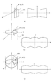
図4を用いて、上記の写像の方式の概略を示す。
【0017】
図4(a)は平面写像であり、原点Oを中心に各センサ面の画像を平面401に投影するものである。
【0018】
平面写像は、広角のレンズで撮影した場合と同様の合成画像が得られ、被写体の直線部は合成画像においても直線として表現される。但し、表現できる画角の範囲は180°未満に限定され、また180°未満であっても、画角が大きくなるに従い周辺部における歪みが増大し画質が劣化する。従って、合成画像の画角としては120°程度までにするのが適当であるといえる。
【0019】
図4(b)は円筒写像であり、各センサ面の画像を、中心線が原点Oを通る円筒402に投影するものである。
【0020】
円筒の側面を展開して得られる画像の水平方向は、角度φで表わされ、360°全周を表現することができる。但し、垂直方向は平面写像と同様であるので、180°未満の画角のみ表わすことができるが、平面写像と同様に、画角が大きくなるに従い周辺部における歪みが増大し画質が劣化する。円筒写像では、被写体の直線部は画像の位置に応じて歪曲する。
【0021】
また、円筒写像は回転軸としてX軸回りの円筒とY軸回りの円筒があるので、撮影条件、即ちパン撮影の場合はY軸回りの円筒(縦円筒)を用い、チルト撮影の場合はX軸回りの円筒(横円筒)を用いるというように、回転軸を選択することが有効である。
【0022】
図4(c)は球面写像であり、原点Oを中心に各センサ面の画像を球面403に投影するものである。
【0023】
球面写像により得られる画像は、水平方向及び垂直方向とも角度を表わす。従って全周のパノラマ画像を表わすことができる。球面写像では、被写体の直線部は画像の位置に応じて歪曲する。
【0024】
球面写像は、パン及びチルト撮影が混在している画像を合成した場合の表現方式として有効である。
【0025】
このように、画像合成する際の写像方式は種々のものがあり、被写体の種類や撮影条件により選択することが有効である。
【0026】
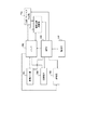
図1に本実施例に係るパノラマ画像合成方式及び装置の概略を示す。
【0027】
図1において701は画像入力部であり合成に用いる画像を入力するものである。画像は不図示の記録媒体に記録されているものを読み込むことにより入力しても良いし、不図示のメモリ等に保持されているものを入力することもできる。また、デジタルカメラ等の撮像素子より得られる映像信号をデジタル化して入力するものであっても構わない。
【0028】
702はメモリであり、画像情報、合成処理に用いる各種パラメータ等の各種情報を保持するものである。
【0029】
703はMPUであり、合成処理全体を制御し、また各種演算処理を行うものである。
【0030】
704は、合成パラメータ生成部であり、隣接する画像同士の位置関係を示す座標空間変換パラメータを生成したり、階調変換パラメータ、隣接画像のつなぎ目位置を算出したりすることによって、合成画像を生成するために必要な各種合成パラメータを生成する。合成パラメータ生成部704は、メモリ702やMPU703と接続されており、メモリ702とは画像データや、各種合成パラメータ等の情報が入出力されている。なお、MPU703に対しては主に制御情報の入出力を行っている。
【0031】
705は、画像合成変換部であり、与えられた写像方式に応じた座標変換パラメータと、合成パラメータ生成部704で生成された、座標空間変換パラメータ等の合成パラメータを用いて、複数枚の画像を合成する。具体的には、MPU703からの制御情報に基づいて、メモリ702にアクセスして、画像データや、座標空間変換パラメータ等の各種合成パラメータを読み込み、座標変換処理とうを行って、合成画像を生成する。また、得られた合成画像をメモリ702に書込む。
【0032】
706はフロッピーディスク等の記録媒体であり、合成したパノラマ画像を記録するものである。
【0033】
707は操作部であり、焦点距離の設定、写像方式の選択等の操作を行うものである。具体的な操作は、マウス等を用いてGUIベースで行ってもよいし、キーボードによるコマンドの直接入力により行ってもよい。
【0034】
708は表示部であり、パノラマ合成された画像、写像変換された画像あるいはGUI等を表示するためのものである。
【0035】
次に、第1の実施例のパノラマ画像合成処理の動作について説明する。
【0036】
隣接する画像の一部が重複した画像を、画像入力部701により入力しメモリ702に保持する。入力する画像は表示部708に表示された候補画像から操作部707による指示により選択することもできる。また、画像ファイルの属性を基に自動的に1セットのパノラマ画像を選択して入力するようにしても良い。
【0037】
合成処理に用いる画像の撮影焦点距離fは、操作部707において設定する。設定方法としては、焦点距離の値を入力するもの、複数の候補の中から選択するもの等がある。また、メモリに保持した画像の属性として撮影焦点距離が予め設定されている場合は、その値を用いることも可能である。
【0038】
画像情報及び撮影焦点距離が設定されると、合成パラメータ生成部704において隣接する画像を合成するためのパラメータを生成する処理が実行される。
【0039】
図5に、合成パラメータ生成のフローを示す。
【0040】
S501では、合成パラメータ設定に用いる2つの画像を設定する。S502では、設定した2つの画像間の重複領域内で対応点の抽出処理を行う。対応点の抽出には、テンプレートマッチング法、相互相関法等の公知の技術を用いればよい。
【0041】
また、処理の効率化のために、公知のCoarse-to-Fineによる階層的な対応点抽出処理を行うことも有効である。
【0042】
S503においては、抽出した対応点情報を基に画像間の座標空間変換パラメータの算出を行う。例として第6図を用いて座標空間変換パラメータ算出の概略を示す。
【0043】
図6は図2におけるパン撮影においてY=0のXZ断面を示したものである。601及び602は隣接する撮影画像に対応したセンサ面を示している。センサ面601に対応したXYZ座標の原点をO、センサ面602に対応したX’Y’Z’座標の原点をO’とすると、座標空間変換パラメータは座標系XYZと座標系X’Y’Z’の関係を表わすものである。S502の対応点抽出処理により得られた対応点を点P及び点P’とすると、この2点間の関係は図6の回転パラメータR及び並進パラメータTにより
P′=R・P+T ・・・(1)
となる。ここで、Rは各軸回りの回転成分(θ,φ,ψ)により得られる回転マトリクスであり、以下のように表される。
【0044】
【外1】

回転マトリクスR及び並進マトリクスTの合成マトリクスMは、以下のように表される。
【0046】
【外2】
合成マトリクスMは、対応点抽出処理により得られる複数個の対応点情報を基に非線形最小自乗法等を用いて算出することができる。パラメータ算出の方式としては、他の公知技術を用いることも可能である。
【0048】
このように、座標系XYZと座標系X'Y'Z'の関係を計算しておくことにより、例えばP(x,y,z)に対応するX'Y'Z'座標上の点がどこなのかを容易に知る手がかりとなる。
【0049】
具体例は後に示すが、この座標空間変換パラメータとして、合成マトリクスMを求めることは、画像間の各点の対応関係を示しており、言い換えれば、任意に入力した2次元の画像情報から、それらを撮影したときの空間的な位置関係を表現しているのである。
【0050】
したがって、あとはこれらの画像を適切な共通面に写像することによって、適切な合成画像を得ることが出来る。
【0051】
S504においては、隣接する画像間の階調を一致させるための補正パラメータを生成する。補正パラメータの生成方式は特開平09−321972の技術を適応する。
【0052】
S505においては、生成した座標空間変換パラメータあるいは階調補正パラメータを用いて隣接する画像間のつなぎ目位置の設定を行う。つなぎ目位置は、座標空間変換パラメータを基にリサンプリングした画素間の差分あるいは相関値を用いて設定する。
【0053】
S506において、隣接する画像間のパラメータ生成がすべて完了したかを判別して、完了していなければ次に合成すべき2画像をS501において再び設定し、合成操作を続ける。
【0054】
完了している場合は、S507において全画像を合成する際の基準位置を設定する。
【0055】
S508では、設定した基準位置を基に、既に得られている座標空間変換パラメータを変換する。
【0056】
以上の処理により、第1図の704において合成パラメータが生成され、メモリ702に保持される。
【0057】
合成パラメータが生成されると、画像変換部705において選択されている写像方式によりパノラマ合成画像が生成される。画像変換部705における処理の概略を図7により説明する。
【0058】
図7は、合成画像を円筒写像変換して生成する場合を示している。図7(a)において710は、円筒写像によるパノラマ合成画像である。ここで、710上の画素Ikを生成する処理により、画像変換部705における処理の概略を示す。図7(b)は、各撮影位置でのセンサ面712及び713間の関係を模式的に示したもので、711は合成画像710をY=Yk断面により表したものである。なお、簡単に考える為に、前述の並進成分Tは無い図となっている。
【0059】
図7(b)において、711面上の点Ik(φk,Yk)を、XYZ座標の点P(x,y,z)として座標変換するときは、以下の式で表すことができる。
【0060】
x=f・sin(φk)
y=Yk ―(4)
z=f・cos(φk)
【0061】
点PをX’Y’Z’座標系の点P’(x’、y’、z’)で表すとすると、点Pと点P’間の変換は、合成パラメータ生成部704において生成された式(3)の座標空間変換パラメータである合成マトリクスMを用いればよく、次式により表すことができる。
【0062】
【外3】
次に、点P'に対応するセンサ面713上の座標P''を次式により求める。
【0064】
【外4】
上記(6)式により、センサ面713(z"=f)上の座標(x'',y'')の画素を参照すれば、合成画像710上の画素Ikの値を知ることが出来る。
【0066】
以上の処理を合成画像710の各画素に対して施すことにより、円筒写像変換された合成画像を生成することができる。
【0067】
合成された画像はメモリ702に保持されると共に、表示部708に表示される。また、必要に応じて記録媒体706に記録される。
【0068】
以下においては、写像方式の変更と、この時の変換処理について示す。
【0069】
操作部707において、ユーザーが任意の写像方式を選択して、写像方式の変更指示をすると、MPUは選択された写像方式に対応した座標変換処理を設定し、前述と同様の処理により705において画像変換処理を実行する。
【0070】
写像方式が変更されると、前述の式(4)を用いた座標変換処理が、選択された新たな写像方式に対応したものに置き換えられる。
【0071】
例えば平面写像に変更した場合は、合成画像の各画素はセンサ面の座標と一致するので、生成する画素Ik(Xk,Yk)に対応する式(4)の座標変換式は以下となる。
【0072】
x=Xk
y=Yk ―(7)
z=f
【0073】
球面写像の場合は、水平及び垂直方向共に等角度ピッチとなるようにサンプリングするので画素Ik(Φk,θk)に対応する座標変換は次式となる。
【0074】
x=f・cos(θk)sin(φk)
y=f・cos(θk) ―(8)
z=f・cos(θk)cos(φk)
【0075】
従って、画像間の関係を表わす座標空間変換パラメータである合成マトリクスMは、いずれの写像方式においても同一のものを用い、選択された写像の種類に応じて(4)式、(7)式及び(8)式の各座標変換式を切り換えることにより、任意の写像による合成画像を得ることが可能となるのである。
【0076】
従来は、写像方式が変更される度に、写像方式に基づいた計算式に、対応点の座標を代入して、合成パラメータ生成処理を実行し、これに基づいて、すべての画素を座標変換していた。
【0077】
これに対して、本実施例のパノラマ画像合成方法では、まず座標空間変換パラメータとして、画像間の各点の対応関係を求めておき、あとは座標変換処理を写像方式に対応して切り換えるだけで合成処理が完了する。したがって、写像方式の切り替えのときには、既に計算した座標空間変換パラメータと、各写像方式に対応して記憶している座標変換処理を用い、入力画像そのものに対して写像変換するだけでよく、つまり新たなパラメータ計算をする必要が無いので、非常に効率良く種々の写像方式による合成画像を得ることが可能となっている。特に写像方式変更時の処理時間を、大幅に短縮することが可能である。同時に、合成した画像に対して変換処理を行わないので、画質も良好な合成画像を得ることが出来るのである。
【0078】
(第2の実施例)
第2の実施例のパノラマ画像合成処理は、以下の特徴を有する。
1) 基準位置をユーザーが任意に変更可能で、変更された基準位置により合成画像が変換される。
2) つなぎ目の修正処理ができる。
3) 以前の合成結果に戻ることができる。
【0079】
以下、上記の特徴を有するパノラマ画像合成方法及び装置の動作について説明する。尚、全体の構成としては図1と同様である。また、予め設定された写像方式により合成画像が生成され、表示部に表示される過程までは、第1実施例と同様であるので説明を省略する。
【0080】
本実施例に係る基準位置の変更の概略を図8及び図9に示す。図8(a)は、平面写像により合成結果が表示されている場合である。図8の合成画像801は、建物を垂直方向にチルトしながら撮影した画像を合成したものである。合成画像は上部が縮小し台形状になっている。802は、基準位置である。
【0081】
図8(b)は、撮影時の被写体とセンサ面との関係を示したものである。803は、被写体の建物であり、804〜806はチルトしながら撮影した各状態でのセンサ面であり、807は合成画像を表わす投影面で、808は合成画像の基準位置である。
【0082】
基準位置の変更は、図1の操作部707によりマウス等により図8(a)の基準位置802を移動させる。基準位置の移動は、キーボードにより移動先の座標を指定することもできるし、矢印キー等により移動させても良い。
【0083】
変更された位置はMPU703に送られる。MPU703は、移動情報を画像変換部705に出力する。画像変換部705においては、移動情報を基に合成画像を修正するための修正マトリクスM'を生成する。
【0084】
画像変換部においては、すべての画像の座標空間変換パラメータである合成マトリクスMをM’により
M2=M・M’・・・(9)
と修正して、合成変換のためのマトリクスM2を生成する。
【0085】
以下、第1実施例と同様に選択されている写像方式を用いて合成画像を生成して、メモリ702に保持し、また表示部708に表示する。
【0086】
図9(a)は基準位置を移動し、合成画像を変換した結果である。901は、合成画像であり、902は現在の基準位置を表わす。
【0087】
図9(b)は被写体とセンサ面との関係である。
【0088】
基準位置を908に移動して、基準位置と基に設定される合成画像の投影面907を用いて合成画像を生成する。
【0089】
投影面907は、被写体の側面909と並行であるので、歪みの無い合成画像901を得ることができる。
【0090】
従来においても、投影面807や907に対応する基準平面を任意に設定し、この平面状に合成画像を形成するものは見られるが、その場合においても、基準平面の変更に伴って、合成パラメータの算出をはじめからやり直す必要が有り、使い勝手が悪かった。
【0091】
しかし本願では、基準位置に対応した座標空間変更パラメータを、既に計算した座標空間変換パラメータに適用して計算するだけであるので、使い勝手が格段に向上する。そして、合成画像を生成する際の基準位置をユーザーの意図する位置に設定することが可能となり、あおり補正等の幾何学補正に柔軟に対応することができる。
【0092】
次に、つなぎ目の修正処理について説明する。図10(a)は、画像の一部が重複するように撮像した画像101及び102である。また図10(b)は、画像101及び画像102を合成した合成画像である。合成画像103において点線はつなぎ目位置を表わす。
【0093】
合成画像103では、つなぎ目付近の画像にずれが生じている。合成画像において、上記のようなずれが生じている場合、本実施例のパノラマ画像合成方法及び装置は図11(a)及び図11(b)に示す修正処理により対応することができる。
【0094】
図11(a)においては、図1の操作部707により撮像した2つの画像101及び102を移動させて、2つの画像の重複部がおおむね一致するように位置合わせする。位置合わせした情報はMPU703に与えられ、MPU703は、合成パラメータ生成部704に位置合わせ情報を与えることにより、合成パラメータ生成部における対応点抽出処理のための情報として用いる。
【0095】
合成パラメータ生成部においては、予めある程度の位置合わせがなされた状態から対応点抽出することができるので、抽出精度及び信頼性を向上することが可能となる。
【0096】
図11(b)においては、図1の操作部707により、撮像した画像101及び102の被写体上の点を対応点として直接設定する。図11(b)においては、点112A−点112Bと点113A―点113Bが対応点ペアとして設定されている。
【0097】
MPU703は、前記対応点ペアの情報を取得し、合成パラメータ生成部704に与える。
【0098】
合成パラメータ生成部704においては、取得した対応点ペアの情報を用いて座標空間変換パラメータを推定することができる。また、取得した対応点ペアは手動で位置合わせされているので、対応点ペアの近傍でのみテンプレートマッチングあるいは相互相関処理を実行して、対応点ペアの精度を向上させて座標変換パラメータの推定に用いても良い。
【0099】
図11(c)は修正後の合成画像114である。画像103と比較してつなぎ目の位置合わせのが滑らかになっている。この修正処理は、ユーザーの欲する結果となるまで繰り返し実行することができる。
【0100】
上述の写像方式の変更処理やつなぎ目の修正処理により、結果的に得られた合成画像が良好となった場合は問題ないが、場合によっては修正前の結果の方が好ましい場合も起こり得る。このような場合に対応するために、本実施例に係るパノラマ画像合成方法では、合成画像が生成されるたびに、合成パラメータ及び合成結果の画像情報を一連の合成処理がすべて終了するまでメモリ702に保持している。
【0101】
例えば図10(b)に示す合成結果103を最初の合成結果として合成カウンタをCs1=1、Cs2=1にセットすると共に、各種合成パラメータ及び合成画像を合成カウンタCs1=1、Cs2=1に対応したメモリ位置に保持する。ここでCs1は、変更・修正処理が繰り替えされるたびに1つずつ増大するカウンタで、Cs2は、現在の状態から、1段階前の状態に戻った上で、新たに変更・修正処理が行われたときに1つずつ増大するカウンタである。
【0102】
次に、変更・修正処理により合成画像114が得られると、合成カウンタをCs1=2、Cs2=1にセットし、合成パラメータ及び合成画像を合成カウンタCs1=2、Cs2=1に対応したメモリ位置に保持する。
【0103】
さらに、変更・修正処理により図12に示すような合成画像120が得られると、合成カウンタをCs1=3、Cs2=1にセットし、合成パラメータ及び合成画像を合成カウンタCs1=3、Cs2=1に対応したメモリ位置に保持する。
【0104】
ここで、ユーザーが操作部707により”戻る”操作を行った場合は、Cs1を現在の位置から1減じてCv1=2として、合成カウンタCs1=2、Cs2=1に対応した合成パラメータ及び合成結果画像をメモリ702から読み出し、合成画像を表示部708に表示すると共に、読み出したパラメータを現時点のパラメータとして置き換える。
【0105】
この時点では図13の合成画像131が表示されている。ここで、変更・修正処理を行った場合は、Csカウンタを一つ進めて、合成カウンタをCs1=2、Cs2=2にセットし、合成パラメータ及び合成画像を合成カウンタCs1=2、Cs2=2に対応したメモリ位置に保持する。この状態では図13の合成画像133が表示されている。
【0106】
さらに修正した場合は、合成画像134が表示され、合成カウンタはCs1=2、Cs2=3となる。
【0107】
上記の処理をMPU703・メモリ702において実行することにより、変更・修正で生成されたすべての画像をメモリに記憶しているので、ユーザーはこれまでに生成した任意の合成画像の状態に、簡単に移行することが可能となる。
【0108】
尚、操作部707においては、左矢印(←)と右矢印(→)により”戻る”方向を指定する。
【0109】
但し、方向の指定方法は他の公知の方法を利用できることは言うまでもない。
【0110】
例えば、カウンタCs1・Cs2の値をそれぞれ入力することによって、これまでに生成した任意の合成画像に移行することも可能である。
【0111】
さらに、上記の場合は合成パラメータと合成画像を保持しているが、合成画像が大きいあるいは多い場合には、メモリの容量を圧迫する可能性もあるので、合成パラメータのみを保持して、画像は合成パラメータを用いて逐次生成するようにする方式も有効である。
【0112】
本実施例のパノラマ画像合成方法及び装置によれば、合成画像のあおり等の補正を柔軟に行うことが可能となり、また修正作業を効率良く実行することができる。
【0113】
なお、上記実施例は複数の機器(たとえばホストコンピュータ、インタフェース機器、リーダ、プリンタ等)から構成されるシステムに適用しても、または一つの機器(たとえば複写機、ファクシミリ装置)からなる装置に適用してもよい。
【0114】
また前述した実施形態の機能を実現する様に各種のデバイスを動作させる様に該各種デバイスと接続された装置あるいはシステム内のコンピュータに、前記実施形態機能を実現するためのソフトウエアのプログラムコードを供給し、そのシステムあるいは装置のコンピュータ(CPUあるいはMPU)を格納されたプログラムに従って前記各種デバイスを動作させることによって実施したものも本願発明の範疇に含まれる。
【0115】
またこの場合、前記ソフトウエアのプログラムコード自体が前述した実施形態の機能を実現することになり、そのプログラムコード自体、及びそのプログラムコードをコンピュータに供給するための手段、例えばかかるプログラムコードを格納した記憶媒体は本発明を構成する。
【0116】
かかるプログラムコードを格納する記憶媒体としては例えばフロッピーディスク、ハードディスク、光ディスク、光磁気ディスク、CD-ROM,、磁気テープ、不揮発性のメモリカード、ROM等を用いることが出来る。
【0117】
またコンピュータが、供給されたプログラムコードを実行することにより、前述の実施形態の機能が実現されるだけではなく、そのプログラムコードが、コンピュータにおいて稼働しているOS(オペレーティングシステム)、あるいは他のアプリケーションソフト等と共同して前述の実施形態の機能が実現される場合にもかかるプログラムコードは本願発明の実施形態に含まれることは言うまでもない。
【0118】
更に供給されたプログラムコードが、コンピュータの機能拡張ボードやコンピュータに接続された機能拡張ユニットに備わるメモリに格納された後そのプログラムコードの指示に基づいてその機能拡張ボードや機能格納ユニットに備わるCPU等が実際の処理の一部または全部を行い、その処理によって前述した実施形態の機能が実現される場合も本願発明に含まれることは言うまでもない。
【0119】
【発明の効果】
以上説明したように、本出願に係る発明によれば、写像方式の切り替えのときには、既に計算した座標空間変換パラメータと、各写像方式に対応して記憶している座標変換処理を用い、入力画像そのものに対して写像変換するだけでよく、つまり新たなパラメータ計算をする必要が無いので、非常に効率良く種々の写像方式による合成画像を得ることが可能となっている。特に写像方式変更時の処理時間を、大幅に短縮することが可能である。同時に、合成した画像に対して変換処理を行わないので、画質も良好な合成画像を得ることが出来るのである。
【図面の簡単な説明】
【図1】パノラマ画像合成処理のブロック図。
【図2】パノラマ撮影の概略図。
【図3】写像変換の概略図。
【図4】写像方式を説明する図。
【図5】合成パラメータ生成処理のフロー。
【図6】合成変換処理の概略図。
【図7】画像合成の説明図。
【図8】画像変換の前記略図。
【図9】画像変換の前記略図。
【図10】撮像画像の概略図。
【図11】修正処理の概略図。
【図12】合成画像の概略図。
【図13】処理シーケンスの概略図。
【符号の説明】
701 画像入力部
702 メモリ
703 MPU
704 合成パラメータ生成部
705 画像合成変換部
706 記録媒体
707 操作部
708 表示部[0001]
BACKGROUND OF THE INVENTION
The present invention relates to an image synthesizing method, an image synthesizing apparatus, and a recording medium that convert and synthesize a plurality of images such that adjacent images have a common subject area.
[0002]
[Prior art]
2. Description of the Related Art Conventionally, when a plurality of images are combined, there is known a method in which an input image is converted and combined by a preset mapping method. As this mapping method, for example, as shown in FIG. 4 (a), a plane mapping in which an image of each sensor surface is projected on the
[0003]
In the conventional panoramic image synthesis method, an appropriate mapping method is selected and set before generating the parameters necessary for the synthesis process, and after the input image is mapped and converted by this mapping method, the positional relationship between a plurality of images is indicated. Parameters (corresponding to coordinate space conversion parameters) were generated from the corresponding point information and synthesized.
[0004]
[Problems to be solved by the invention]
However, for example, when trying to create a composite image by changing the mapping method, a plurality of images are input again, map conversion is performed by another mapping method, and complex image composition processing is repeatedly executed. In other words, the process for parameter generation must be re-executed from the beginning.ThisIt was time consuming and very inefficient.
[0005]
In addition, there are some which convert and display a map with respect to the synthesized image, but this is a conversion process again based on the once synthesized image. That is, since the image conversion process is executed at least twice on the original image, there is a problem that the image quality of the image whose mapping has been changed is deteriorated.
[0006]
In view of the above problems, the object of the invention according to the present application is to reduce the processing time and obtain a composite image with good image quality when attempting to create a composite image by changing the mapping method. is there.
[0007]
[Means for Solving the Problems]
In order to solve the above-described problem, an image composition device according to the invention of the present application includes an image input unit that inputs a plurality of images in which an overlap region exists between at least two images, and is adjacent to the plurality of images. A parameter generation unit that generates a coordinate space conversion parameter obtained from the positional relationship between images, a holding unit that stores the coordinate space conversion parameter in a memory, and a mapping method that is a plurality of mapping methods in response to a user operation. Switching means for switching among them, changing means for changing a coordinate conversion formula used when combining the plurality of images in correspondence with the switched mapping method, and coordinate space conversion parameters stored in advance in the memory And an image synthesizing means for synthesizing the plurality of images using the modified coordinate transformation formula.
[0012]
DETAILED DESCRIPTION OF THE INVENTION
(First embodiment)
As shown in FIG. 2, the image used in the panoramic image synthesis method and apparatus according to the present embodiment is obtained by inputting an image of the
[0013]
The direction of rotation includes the Y axis (hereinafter referred to as pan) or the X axis (hereinafter referred to as tilt) in FIG. As shown in FIG. 2, a panoramic image covering an arbitrary angle of view can be obtained by inputting and synthesizing an image.
[0014]
Here, the relationship between the panoramic image and the mapping will be described. FIG. 3 is a cross-sectional view at Y = 0 in each imaging state of FIG. The origin O and the coordinate axes XYZ are set based on the
[0015]
In order to combine a plurality of images taken in different directions and express them as one image, it is necessary to map the images onto a certain surface. As the mapping method, for example, as shown in FIG. 3, there are a cylindrical mapping for projecting the image of each sensor surface onto the cylindrical surface 310, a planar mapping for projecting onto the plane 320, and the like.
[0016]
An outline of the above mapping method will be described with reference to FIG.
[0017]
FIG. 4A is a plane mapping, in which an image of each sensor surface is projected onto the
[0018]
In the planar mapping, a composite image similar to that obtained by photographing with a wide-angle lens is obtained, and the straight line portion of the subject is expressed as a straight line in the composite image. However, the range of view angles that can be expressed is limited to less than 180 °. Even if the view angle is less than 180 °, distortion in the peripheral portion increases and the image quality deteriorates as the view angle increases. Therefore, it can be said that it is appropriate to set the angle of view of the composite image to about 120 °.
[0019]
FIG. 4B is a cylindrical mapping in which an image of each sensor surface is projected onto a
[0020]
The horizontal direction of the image obtained by developing the side surface of the cylinder is represented by an angle φ, and can represent the entire 360 ° circumference. However, since the vertical direction is the same as that of the planar mapping, only an angle of view of less than 180 ° can be expressed. However, as with the planar mapping, distortion in the peripheral portion increases and the image quality deteriorates as the angle of view increases. In the cylindrical mapping, the straight line portion of the subject is distorted according to the position of the image.
[0021]
In addition, since the cylindrical mapping includes a cylinder around the X axis and a cylinder around the Y axis as rotation axes, a cylinder around the Y axis (vertical cylinder) is used for shooting conditions, that is, pan shooting, and X is used for tilt shooting. It is effective to select a rotation axis such as using a cylinder (horizontal cylinder) around the axis.
[0022]
FIG. 4C shows a spherical mapping, in which an image of each sensor surface is projected onto the
[0023]
An image obtained by spherical mapping represents an angle in both the horizontal direction and the vertical direction. Therefore, a panoramic image of the entire circumference can be represented. In the spherical mapping, the straight line portion of the subject is distorted according to the position of the image.
[0024]
The spherical mapping is effective as an expression method when an image in which pan and tilt photography is mixed is synthesized.
[0025]
As described above, there are various mapping methods at the time of image composition, and it is effective to select according to the type of subject and photographing conditions.
[0026]
FIG. 1 schematically shows a panoramic image composition method and apparatus according to this embodiment.
[0027]
In FIG. 1,
[0028]
[0029]
[0030]
A composite
[0031]
[0032]
[0033]
[0034]
[0035]
Next, the operation of the panoramic image synthesis process of the first embodiment will be described.
[0036]
An image in which a part of adjacent images overlaps is input by the
[0037]
The shooting focal length f of the image used for the composition process is set by the
[0038]
When the image information and the photographing focal length are set, the synthesis
[0039]
FIG. 5 shows a synthesis parameter generation flow.
[0040]
In S501, two images to be used for the synthesis parameter setting are set. In S502, the corresponding points are extracted in the overlapping area between the two set images. For extracting the corresponding points, a known technique such as a template matching method or a cross-correlation method may be used.
[0041]
In order to improve processing efficiency, it is also effective to perform a hierarchical corresponding point extraction process by a known coarse-to-fine.
[0042]
S503In, a coordinate space conversion parameter between images is calculated based on the extracted corresponding point information. An outline of coordinate space conversion parameter calculation will be shown using FIG. 6 as an example.
[0043]
FIG. 6 shows an XZ cross section of Y = 0 in the pan photographing in FIG.
P ′ = R · P + T (1)
It becomes. Here, R is a rotation matrix obtained by rotation components (θ, φ, ψ) around each axis, and is expressed as follows.
[0044]
[Outside 1]
A composite matrix M of the rotation matrix R and the translation matrix T is expressed as follows.
[0046]
[Outside 2]
The composite matrix M can be calculated using a nonlinear least square method or the like based on a plurality of pieces of corresponding point information obtained by the corresponding point extraction process. Other known techniques may be used as the parameter calculation method.
[0048]
Thus, by calculating the relationship between the coordinate system XYZ and the coordinate system X′Y′Z ′, for example, where is the point on the X′Y′Z ′ coordinate corresponding to P (x, y, z) It becomes a clue to know easily.
[0049]
Although a specific example will be described later, obtaining the synthesis matrix M as the coordinate space conversion parameter indicates the correspondence of each point between images, in other words, from two-dimensional image information arbitrarily input, It expresses the spatial positional relationship when shooting.
[0050]
Therefore, an appropriate composite image can be obtained by mapping these images onto an appropriate common plane.
[0051]
In S504, a correction parameter for matching the gradation between adjacent images is generated. The correction parameter generation method is adapted from the technique disclosed in Japanese Patent Laid-Open No. 09-321972.
[0052]
In S505, the generated coordinatesspaceA joint position between adjacent images is set using a conversion parameter or a gradation correction parameter. The joint position is set using a difference or correlation value between pixels resampled based on the coordinate space conversion parameter.
[0053]
In step S506, it is determined whether all parameter generation between adjacent images has been completed. If not, the next two images to be combined are set again in step S501, and the combining operation is continued.
[0054]
If completed, a reference position for combining all images is set in S507.
[0055]
In S508, the already obtained coordinate space conversion parameter is converted based on the set reference position.
[0056]
Through the above processing, a synthesis parameter is generated at 704 in FIG. 1 and held in the
[0057]
When the synthesis parameter is generated, a panorama composite image is generated by the mapping method selected by the
[0058]
FIG. 7 shows a case where a composite image is generated by cylindrical mapping conversion. In FIG. 7A,
[0059]
In FIG. 7B, when the point Ik (φk, Yk) on the
[0060]
x = f · sin (φk)
y = Yk -(4)
z = f · cos (φk)
[0061]
If the point P is represented by a point P ′ (x ′, y ′, z ′) in the X′Y′Z ′ coordinate system, the conversion between the point P and the point P ′ is generated by the synthesis
[0062]
[Outside 3]
Next, a coordinate P ″ on the
[0064]
[Outside 4]
By referring to the pixel at the coordinate (x ″, y ″) on the sensor surface 713 (z ″ = f), the value of the pixel Ik on the
[0066]
By performing the above processing on each pixel of the
[0067]
The synthesized image is held in the
[0068]
In the following, the change of the mapping method and the conversion process at this time will be described.
[0069]
In the
[0070]
When the mapping method is changed, the coordinate conversion process using the above-described equation (4) is replaced with one corresponding to the selected new mapping method.
[0071]
For example, when it is changed to a planar mapping, each pixel of the composite image matches the coordinates of the sensor surface, so the coordinate conversion equation of the equation (4) corresponding to the pixel Ik (Xk, Yk) to be generated is as follows.
[0072]
x = Xk
y = Yk -(7)
z = f
[0073]
In the case of a spherical mapping, sampling is performed so that the horizontal and vertical directions have an equiangular pitch, so the coordinate transformation corresponding to the pixel Ik (Φk, θk) is given by
[0074]
x = f · cos (θk) Sin (φk)
y = f · cos (θk-(8)
z = f · cos (θk) Cos (φk)
[0075]
Therefore, a coordinate space conversion parameter representing the relationship between imagesIs a composite matrixM is the same in any mapping method, and can be arbitrarily set by switching the coordinate conversion formulas (4), (7) and (8) according to the type of mapping selected. It is possible to obtain a composite image by mapping.
[0076]
Conventionally, every time the mapping method is changed, the coordinates of the corresponding points are substituted into the calculation formula based on the mapping method, and the composite parameter generation process is executed. Based on this, the coordinates of all pixels are converted. It was.
[0077]
On the other hand, in the panoramic image synthesis method of the present embodiment, first, the correspondence of each point between images is obtained as a coordinate space conversion parameter, and then the coordinate conversion processing is simply switched according to the mapping method. The synthesis process is completed. Therefore, at the time of switching the mapping method, it is only necessary to perform mapping conversion on the input image itself using the coordinate space conversion parameter already calculated and the coordinate conversion processing stored corresponding to each mapping method. Therefore, it is possible to obtain a synthesized image by various mapping methods very efficiently. In particular, the processing time when changing the mapping method can be greatly reduced. At the same time, since a conversion process is not performed on the synthesized image, a synthesized image with good image quality can be obtained.
[0078]
(Second embodiment)
The panoramic image synthesis process of the second embodiment has the following characteristics.
1) The reference position can be arbitrarily changed by the user, and the composite image is converted by the changed reference position.
2) The joint can be corrected.
3) It is possible to return to the previous synthesis result.
[0079]
The operation of the panoramic image synthesis method and apparatus having the above features will be described below. The overall configuration is the same as in FIG. Further, the process until a composite image is generated by a preset mapping method and displayed on the display unit is the same as that in the first embodiment, and thus the description thereof is omitted.
[0080]
The outline of the change of the reference position according to the present embodiment is shown in FIGS. FIG. 8A shows a case where the synthesis result is displayed by a planar mapping. The composite image 801 in FIG. 8 is a composite of images taken while tilting the building in the vertical direction. The upper part of the composite image is reduced to a trapezoidal shape.
[0081]
FIG. 8B shows the relationship between the subject and the sensor surface at the time of shooting.
[0082]
To change the reference position, the
[0083]
The changed position is sent to the
[0084]
In the image converter, the coordinate space conversion parameters for all imagesIs a composite matrixM by M ’
M2 = M · M ′ (9)
To generate a matrix M2 for composite conversion.
[0085]
Thereafter, a composite image is generated using the selected mapping method in the same manner as in the first embodiment, stored in the
[0086]
FIG. 9A shows the result of moving the reference position and converting the composite image.
[0087]
FIG. 9B shows the relationship between the subject and the sensor surface.
[0088]
The reference position is moved to 908, and a composite image is generated using the
[0089]
Since the
[0090]
Conventionally, it is possible to arbitrarily set a reference plane corresponding to the projection planes 807 and 907 and form a composite image in this plane. However, even in this case, the composite parameter is changed along with the change of the reference plane. It was necessary to redo the calculation from the beginning and it was not easy to use.
[0091]
However, in this application, since the coordinate space change parameter corresponding to the reference position is simply applied to the already calculated coordinate space conversion parameter, the usability is greatly improved. Then, it becomes possible to set the reference position for generating the composite image to a position intended by the user, and it is possible to flexibly cope with geometric correction such as tilt correction.
[0092]
Next, the joint correction process will be described. FIG. 10A shows
[0093]
In the
[0094]
In FIG. 11A, the two
[0095]
In the synthesis parameter generation unit, corresponding points can be extracted from a state where a certain degree of alignment has been performed in advance, so that it is possible to improve extraction accuracy and reliability.
[0096]
In FIG. 11B, the points on the subject of the captured
[0097]
The
[0098]
In the synthesis
[0099]
FIG. 11C shows a
[0100]
There is no problem when the resultant composite image is improved as a result of the above-described mapping method change processing and joint correction processing, but in some cases, the result before correction may be preferable. In order to deal with such a case, in the panoramic image synthesis method according to the present embodiment, each time a composite image is generated, the
[0101]
For example, with the
[0102]
Next, when the
[0103]
Furthermore, by change / correction processingAs shown in FIG.When the
[0104]
Here, when the user performs a “return” operation using the
[0105]
At this time, the
[0106]
When further correction is made, the
[0107]
By executing the above processing in the
[0108]
In the
[0109]
However, it goes without saying that other known methods can be used as the direction designation method.
[0110]
For example, by inputting the values of the counters Cs1 and Cs2, it is possible to shift to any composite image generated so far.
[0111]
Furthermore, in the above case, the composite parameter and composite image are held, but if the composite image is large or large, there is a possibility that the memory capacity will be compressed. It is also effective to use a method of generating sequentially using synthesis parameters.
[0112]
According to the panoramic image synthesizing method and apparatus of the present embodiment, it is possible to flexibly correct the tilt and the like of the synthesized image, and it is possible to efficiently perform the correction work.
[0113]
The above embodiment can be applied to a system composed of a plurality of devices (for example, a host computer, an interface device, a reader, a printer, etc.) or to an apparatus composed of a single device (for example, a copier, a facsimile machine). May be.
[0114]
In addition, a software program code for realizing the functions of the embodiment is provided in a computer in an apparatus or a system connected to the various devices so as to operate the various devices so as to realize the functions of the above-described embodiments. What is implemented by operating the various devices in accordance with a program stored in the computer (CPU or MPU) of the system or apparatus supplied is also included in the scope of the present invention.
[0115]
In this case, the software program code itself realizes the functions of the above-described embodiments, and the program code itself and means for supplying the program code to the computer, for example, the program code are stored. The storage medium constitutes the present invention.
[0116]
As a storage medium for storing the program code, for example, a floppy disk, a hard disk, an optical disk, a magneto-optical disk, a CD-ROM, a magnetic tape, a nonvolatile memory card, a ROM, or the like can be used.
[0117]
The computer not only realizes the functions of the above-described embodiments by executing the supplied program code, but also the OS (operating system) or other application in which the program code is running on the computer. It goes without saying that such program code is also included in the embodiment of the present invention even when the functions of the above-described embodiment are realized in cooperation with software or the like.
[0118]
Further, after the supplied program code is stored in the memory provided in the function expansion board of the computer or the function expansion unit connected to the computer, the CPU provided in the function expansion board or function storage unit based on the instruction of the program code However, it is needless to say that the present invention also includes a case where the function of the above-described embodiment is realized by performing part or all of the actual processing.
[0119]
【The invention's effect】
As described above, according to the invention according to the present application, at the time of switching the mapping method, the coordinate space conversion parameter already calculated and the coordinate conversion processing stored corresponding to each mapping method are used, and the input image is used. It is only necessary to perform mapping conversion on itself, that is, it is not necessary to calculate a new parameter, so that it is possible to obtain composite images by various mapping methods very efficiently. In particular, the processing time when changing the mapping method can be greatly reduced. At the same time, since a conversion process is not performed on the synthesized image, a synthesized image with good image quality can be obtained.
[Brief description of the drawings]
FIG. 1 is a block diagram of panoramic image synthesis processing.
FIG. 2 is a schematic diagram of panoramic shooting.
FIG. 3 is a schematic diagram of map conversion.
FIG. 4 is a diagram illustrating a mapping method.
FIG. 5 is a flowchart of a synthesis parameter generation process.
FIG. 6 is a schematic diagram of a composite conversion process.
FIG. 7 is an explanatory diagram of image composition.
FIG. 8 is a schematic diagram of image conversion.
FIG. 9 is a schematic diagram of image conversion.
FIG. 10 is a schematic diagram of a captured image.
FIG. 11 is a schematic diagram of correction processing.
FIG. 12 is a schematic diagram of a composite image.
FIG. 13 is a schematic diagram of a processing sequence.
[Explanation of symbols]
701 Image input unit
702 memory
703 MPU
704 Synthesis parameter generator
705 Image composition conversion unit
706 Recording medium
707 operation unit
708 display
Claims (6)
前記複数の画像のうち隣接する画像同士の位置関係から得られる座標空間変換パラメータを生成するパラメータ生成手段と、
前記座標空間変換パラメータをメモリに保持する保持手段と、
ユーザの操作に応答して、写像方式を複数の写像方式の中で切り替える切り替え手段と、
前記切り替えられた写像方式に対応して、前記複数の画像を合成する際に用いられる座標変換式を変更する変更手段と、
前記メモリに予め保持された座標空間変換パラメータと前記変更された座標変換式とを用いて前記複数の画像を合成する画像合成手段とを備えた事を特徴とする画像合成装置。Image input means for inputting a plurality of images in which an overlapping region exists between at least two images;
Parameter generating means for generating a coordinate space conversion parameter obtained from a positional relationship between adjacent images among the plurality of images;
Holding means for holding the coordinate space conversion parameter in a memory;
Switching means for switching the mapping method among a plurality of mapping methods in response to a user operation;
Corresponding to the switched mapping method, changing means for changing a coordinate conversion formula used when combining the plurality of images,
An image synthesizing apparatus comprising: an image synthesizing unit that synthesizes the plurality of images using a coordinate space transformation parameter held in advance in the memory and the changed coordinate transformation equation.
前記複数の画像のうち隣接する画像同士の位置関係から得られる座標空間変換パラメータを生成するパラメータ生成工程と、
前記座標空間変換パラメータをメモリに保持する保持工程と、
ユーザの操作に応答して、写像方式を複数の写像方式の中で切り替える切り替え工程と、
前記切り替えられた写像方式に対応して、前記複数の画像を合成する際に用いられる座標変換式を変更する変更工程と、
前記メモリに予め保持された座標空間変換パラメータと前記変更された座標変換式とを用いて前記複数の画像を合成する画像合成工程とを備えた事を特徴とする画像合成方法。An image input step of inputting a plurality of images in which an overlap region exists between at least two images;
A parameter generation step of generating a coordinate space conversion parameter obtained from a positional relationship between adjacent images among the plurality of images;
A holding step of holding the coordinate space conversion parameter in a memory;
A switching step of switching a mapping method among a plurality of mapping methods in response to a user operation;
Corresponding to the switched mapping method, a change step of changing a coordinate conversion formula used when combining the plurality of images,
An image synthesizing method comprising: an image synthesizing step of synthesizing the plurality of images using a coordinate space transformation parameter held in advance in the memory and the changed coordinate transformation equation.
前記複数の画像のうち隣接する画像同士の位置関係から得られる座標空間変換パラメータを生成するパラメータ生成工程と、
前記座標空間変換パラメータをメモリに保持する保持工程と、
ユーザの操作に応答して、写像方式を複数の写像方式の中で切り替える切り替え工程と、
前記切り替えられた写像方式に対応して、前記複数の画像を合成する際に用いられる座標変換式を変更する変更工程と、
前記メモリに予め保持された座標空間変換パラメータと前記変更された座標変換式とを用いて前記複数の画像を合成する画像合成工程とを備えた事を特徴とする画像合成方法をコンピュータに実行させるためのプログラムをコンピュータ読出し可能に記憶した記憶媒体。An image input step of inputting a plurality of images in which an overlap region exists between at least two images;
A parameter generation step of generating a coordinate space conversion parameter obtained from a positional relationship between adjacent images among the plurality of images;
A holding step of holding the coordinate space conversion parameter in a memory;
A switching step of switching a mapping method among a plurality of mapping methods in response to a user operation;
Corresponding to the switched mapping method, a change step of changing a coordinate conversion formula used when combining the plurality of images,
An image synthesizing method comprising: an image synthesizing step of synthesizing the plurality of images using a coordinate space transformation parameter stored in advance in the memory and the changed coordinate transformation equation. A storage medium storing a program for reading in a computer-readable manner.
Priority Applications (3)
| Application Number | Priority Date | Filing Date | Title |
|---|---|---|---|
| JP23047699A JP4346742B2 (en) | 1999-08-17 | 1999-08-17 | Image composition method, image composition apparatus, and storage medium |
| US09/624,385 US7098914B1 (en) | 1999-07-30 | 2000-07-27 | Image synthesis method, image synthesis apparatus, and storage medium |
| US11/474,999 US8379054B2 (en) | 1999-07-30 | 2006-06-27 | Image synthesis method, image synthesis apparatus, and storage medium |
Applications Claiming Priority (1)
| Application Number | Priority Date | Filing Date | Title |
|---|---|---|---|
| JP23047699A JP4346742B2 (en) | 1999-08-17 | 1999-08-17 | Image composition method, image composition apparatus, and storage medium |
Publications (3)
| Publication Number | Publication Date |
|---|---|
| JP2001052152A JP2001052152A (en) | 2001-02-23 |
| JP2001052152A5 JP2001052152A5 (en) | 2006-10-05 |
| JP4346742B2 true JP4346742B2 (en) | 2009-10-21 |
Family
ID=16908418
Family Applications (1)
| Application Number | Title | Priority Date | Filing Date |
|---|---|---|---|
| JP23047699A Expired - Fee Related JP4346742B2 (en) | 1999-07-30 | 1999-08-17 | Image composition method, image composition apparatus, and storage medium |
Country Status (1)
| Country | Link |
|---|---|
| JP (1) | JP4346742B2 (en) |
Families Citing this family (10)
| Publication number | Priority date | Publication date | Assignee | Title |
|---|---|---|---|---|
| JP4355535B2 (en) * | 2003-08-07 | 2009-11-04 | 株式会社岩根研究所 | 360 degree image conversion processing device |
| JP2005202593A (en) * | 2004-01-14 | 2005-07-28 | Seiko Epson Corp | Image processing device, program and method |
| TWI393072B (en) | 2008-07-23 | 2013-04-11 | Pixart Imaging Inc | Multi-sensor array module with wide viewing angle; image calibration method, operating method and application for the same |
| JP5163960B2 (en) * | 2009-03-04 | 2013-03-13 | カシオ計算機株式会社 | Tape printing apparatus, method for creating a composite label in which an image and a document are combined, and a storage medium storing a composite label creation program |
| KR101081934B1 (en) | 2010-02-25 | 2011-11-09 | 성균관대학교산학협력단 | Image generation apparatus and panoramic image generation method thereof |
| JP2013101525A (en) * | 2011-11-09 | 2013-05-23 | Sony Corp | Image processing device, method, and program |
| JP6450589B2 (en) * | 2014-12-26 | 2019-01-09 | 株式会社モルフォ | Image generating apparatus, electronic device, image generating method, and program |
| JP5846549B1 (en) | 2015-02-06 | 2016-01-20 | 株式会社リコー | Image processing system, image processing method, program, imaging system, image generation apparatus, image generation method and program |
| JP2018081570A (en) * | 2016-11-17 | 2018-05-24 | 株式会社Nttファシリティーズ | Information visualization system, information visualization method, and program |
| CN109242772B (en) * | 2018-08-23 | 2023-01-31 | 上海圭目机器人有限公司 | Airport pavement surface image splicing method based on intelligent platform area-array camera acquisition |
-
1999
- 1999-08-17 JP JP23047699A patent/JP4346742B2/en not_active Expired - Fee Related
Also Published As
| Publication number | Publication date |
|---|---|
| JP2001052152A (en) | 2001-02-23 |
Similar Documents
| Publication | Publication Date | Title |
|---|---|---|
| US8379054B2 (en) | Image synthesis method, image synthesis apparatus, and storage medium | |
| JP4363151B2 (en) | Imaging apparatus, image processing method thereof, and program | |
| US7317558B2 (en) | System and method for image processing of multiple images | |
| JP4010754B2 (en) | Image processing apparatus, image processing method, and computer-readable recording medium | |
| JP4196216B2 (en) | Image composition system, image composition method and program | |
| JP2004334843A (en) | Method of composting image from two or more images | |
| JP4975679B2 (en) | Notebook information processing apparatus and projective transformation parameter calculation method | |
| JP4346742B2 (en) | Image composition method, image composition apparatus, and storage medium | |
| JPH1049704A (en) | Image conversion method | |
| JPWO2020194470A1 (en) | Image generator, image generator, and image generator | |
| JPH10126665A (en) | Image composing device | |
| JP3109580B2 (en) | IMAGE INPUT DEVICE AND COMPUTER-READABLE RECORDING MEDIUM RECORDING IMAGE PROCESSING PROGRAM FOR IMAGE INPUT DEVICE | |
| JP4174122B2 (en) | Image processing method, apparatus, and recording medium | |
| JP4363154B2 (en) | Imaging apparatus, image processing method thereof, and program | |
| JP2001052152A5 (en) | ||
| JP4007524B2 (en) | Image composition method and apparatus, and information recording medium | |
| JP4363153B2 (en) | Imaging apparatus, image processing method thereof, and program | |
| JP2005182098A (en) | Device and method for generating and displaying composite image | |
| JP4458720B2 (en) | Image input apparatus and program | |
| JP2004258794A (en) | Method, device, and computer program for editing three-dimensional model | |
| JP2020161107A (en) | Image generation device, image generation method, and image generation program | |
| JP4401484B2 (en) | Image composition apparatus, control method therefor, and storage medium | |
| JP4154023B2 (en) | Image composition method, image composition apparatus, image composition system, and storage medium | |
| JP5687370B2 (en) | Image processing apparatus, image processing method, image processing program, and recording medium | |
| JP4591343B2 (en) | Image processing apparatus, imaging apparatus, image processing method, and program |
Legal Events
| Date | Code | Title | Description |
|---|---|---|---|
| A521 | Written amendment |
Free format text: JAPANESE INTERMEDIATE CODE: A523 Effective date: 20060810 |
|
| A621 | Written request for application examination |
Free format text: JAPANESE INTERMEDIATE CODE: A621 Effective date: 20060810 |
|
| A977 | Report on retrieval |
Free format text: JAPANESE INTERMEDIATE CODE: A971007 Effective date: 20081205 |
|
| A131 | Notification of reasons for refusal |
Free format text: JAPANESE INTERMEDIATE CODE: A131 Effective date: 20090106 |
|
| A521 | Written amendment |
Free format text: JAPANESE INTERMEDIATE CODE: A523 Effective date: 20090223 |
|
| A131 | Notification of reasons for refusal |
Free format text: JAPANESE INTERMEDIATE CODE: A131 Effective date: 20090428 |
|
| A521 | Written amendment |
Free format text: JAPANESE INTERMEDIATE CODE: A523 Effective date: 20090515 |
|
| TRDD | Decision of grant or rejection written | ||
| A01 | Written decision to grant a patent or to grant a registration (utility model) |
Free format text: JAPANESE INTERMEDIATE CODE: A01 Effective date: 20090714 |
|
| A01 | Written decision to grant a patent or to grant a registration (utility model) |
Free format text: JAPANESE INTERMEDIATE CODE: A01 |
|
| A61 | First payment of annual fees (during grant procedure) |
Free format text: JAPANESE INTERMEDIATE CODE: A61 Effective date: 20090715 |
|
| R150 | Certificate of patent or registration of utility model |
Free format text: JAPANESE INTERMEDIATE CODE: R150 |
|
| FPAY | Renewal fee payment (event date is renewal date of database) |
Free format text: PAYMENT UNTIL: 20120724 Year of fee payment: 3 |
|
| FPAY | Renewal fee payment (event date is renewal date of database) |
Free format text: PAYMENT UNTIL: 20120724 Year of fee payment: 3 |
|
| FPAY | Renewal fee payment (event date is renewal date of database) |
Free format text: PAYMENT UNTIL: 20130724 Year of fee payment: 4 |
|
| LAPS | Cancellation because of no payment of annual fees |