JP4343565B2 - Packaging equipment - Google Patents
Packaging equipment Download PDFInfo
- Publication number
- JP4343565B2 JP4343565B2 JP2003081632A JP2003081632A JP4343565B2 JP 4343565 B2 JP4343565 B2 JP 4343565B2 JP 2003081632 A JP2003081632 A JP 2003081632A JP 2003081632 A JP2003081632 A JP 2003081632A JP 4343565 B2 JP4343565 B2 JP 4343565B2
- Authority
- JP
- Japan
- Prior art keywords
- packaging
- sheet
- triangular
- packaging sheet
- opening
- Prior art date
- Legal status (The legal status is an assumption and is not a legal conclusion. Google has not performed a legal analysis and makes no representation as to the accuracy of the status listed.)
- Expired - Fee Related
Links
Images


Classifications
-
- B—PERFORMING OPERATIONS; TRANSPORTING
- B65—CONVEYING; PACKING; STORING; HANDLING THIN OR FILAMENTARY MATERIAL
- B65B—MACHINES, APPARATUS OR DEVICES FOR, OR METHODS OF, PACKAGING ARTICLES OR MATERIALS; UNPACKING
- B65B9/00—Enclosing successive articles, or quantities of material, e.g. liquids or semiliquids, in flat, folded, or tubular webs of flexible sheet material; Subdividing filled flexible tubes to form packages
- B65B9/06—Enclosing successive articles, or quantities of material, in a longitudinally-folded web, or in a web folded into a tube about the articles or quantities of material placed upon it
-
- B—PERFORMING OPERATIONS; TRANSPORTING
- B65—CONVEYING; PACKING; STORING; HANDLING THIN OR FILAMENTARY MATERIAL
- B65B—MACHINES, APPARATUS OR DEVICES FOR, OR METHODS OF, PACKAGING ARTICLES OR MATERIALS; UNPACKING
- B65B41/00—Supplying or feeding container-forming sheets or wrapping material
- B65B41/18—Registering sheets, blanks, or webs
-
- B—PERFORMING OPERATIONS; TRANSPORTING
- B65—CONVEYING; PACKING; STORING; HANDLING THIN OR FILAMENTARY MATERIAL
- B65B—MACHINES, APPARATUS OR DEVICES FOR, OR METHODS OF, PACKAGING ARTICLES OR MATERIALS; UNPACKING
- B65B41/00—Supplying or feeding container-forming sheets or wrapping material
- B65B41/12—Feeding webs from rolls
Landscapes
- Engineering & Computer Science (AREA)
- Mechanical Engineering (AREA)
- Containers And Plastic Fillers For Packaging (AREA)
- Package Closures (AREA)
- Basic Packing Technique (AREA)
Description
【0001】
【発明の属する技術分野】
本発明は錠剤や散薬等の被包装物を包装する包装装置に関する。
【0002】
【従来の技術】
従来、錠剤や散薬等の薬剤を処方に基づいて1回服用分づつ包装する薬剤包装装置が種々提供されている。なかでも、予め長手方向に2つ折りされた細長い包装シートを巻回したロールを使用するものがある。
【0003】
この装置では、図21,22に示すように、ロールから包装シート100を供給し、該包装シート100を開口してその開口からホッパーノズル101により1包分の薬剤を導入した後、該薬剤を閉じ込めるように包装シート100をヒーターローラ102によりシールするようになっている。
【0004】
前記ヒーターローラ102は、包装シート100の開口縁を長手方向にシールする横シール103と、該包装シート100を横切るように開口縁から折り目までをシールする縦シール104とを行うが、縦シール104を行うとき、図21に示すように、横シール103の近傍で長手方向に延びる皺105が発生するという問題があった。この皺105は、薬剤を導入したときの包装シート100の膨らみや、包装シート100の横シール103が行なわれる部分と縦シール104が行われる部分との張力の相違等に起因していると考えられる。このような皺105が発生すると、見栄えが悪いうえ、切り離しが困難になる。場合によっては、気密性が低くなったり、穴になって隣の薬剤を汚染する虞れがあった。
【0005】
【発明が解決しようとする課題】
本発明は前記従来の問題に鑑みてなされたもので、包装シートに皺が発生することがない包装装置を提供することを課題とする。
【0006】
【課題を解決するための手段】
前記課題を解決するために、本発明は、予め長手方向に2つ折りされた細長い包装シートを供給するシート供給部と、該シート供給部から供給される前記包装シートを開口してその開口から被包装物を導入する被包装物導入部と、導入された前記被包装物を閉じ込めるように前記包装シートをシールするシール部とを備えた包装装置において、前記シート供給部と前記シール部の間で、前記包装シートの開口の縁部近傍に内側から外方向に作用する押圧部を設けたものである。
【0007】
前記手段からなる発明では、前記押圧部が包装シートの開口の縁部近傍に内側から接触して押圧するので、包装シートの横シールが行なわれる部分と縦シールが行われる部分との張力の差が無くなり、皺の発生が防止される。
【0008】
前記被包装物導入部は前記包装シートの開口に挿入されるノズルを有するホッパーからなり、前記押圧部は前記ホッパーのノズルの外面に設けることができる。
【0009】
前記シート供給部と前記被包装物導入部の間で前記シートを略V字型に開口する三角部材を配設することができる。
【0010】
前記三角部材は三角板とすることができ、この場合、前記三角板の側縁に前記押圧部を設けることが好ましい。
【0011】
前記三角板は、前記開口の縁部から前記押圧部までの距離を調整できるように移動可能であることが好ましい。
【0012】
前記被包装物導入部と前記三角板との間、または前記シート供給部と前記三角板との間で、前記包装シートの開口内に皺抑え板を設け、該皺抑え板の側縁に前記押圧部を設けることもできる。
【0013】
前記皺抑え板は、前記開口の縁部から前記押圧部までの距離を調整できるように移動可能であることが好ましい。
【0014】
前記三角部材はブロック状の三角体とすることもできる。この三角体は、下部が逆三角形に形成された板状の基部と、該基部の下半分から突出する略三角錐形のブロック部とからなることが好ましい。この場合、前記基部の両側縁から前記ブロック体の斜面に沿って延びるように前記押圧部を設けることが好ましい。また、前記基部の下端からブロック部の斜面に沿って延びる稜線が前記包装シートの折目に沿うようにすることが好ましい。
【0015】
前記被包装物導入部は前記包装シートの開口に挿入されるノズルを有するホッパーからなり、前記ノズルの上流側に包装シートを挟持可能な1対の挟持片からなる挟持ユニットを設け、前記被包装物の導入時に前記1対の挟持片を閉じることが好ましい。これにより、被包装物がノズルと挟持ユニットの間からすり抜けるのを防止することができる。
【0016】
前記1対の挟持片は、互いに噛合するセグメントギヤにより開閉可能に設けられ、前記1対の挟持片のうち一方の挟持片は、アームと、セグメントギヤを有するアームベースからなり、前記アームは、前記アームベースに回動可能に取り付けられ、前記1対の挟持片が開いた状態で当該アームを引くと倒れるようにすることが好ましい。これにより、1対の挟持片の間に包装シートを簡単に通すことができる。
【0017】
前記1対の挟持片は先端の対向部分にパッドを有し、一方のパッドは、前記ノズルに近接しかつ前記ノズルの軸に平行に延びる垂直部を有することが好ましい。これにより、一方のパッドの垂直部と他方のパッドが線接触して包装シートを挟持するので、被包装物がノズルと挟持ユニットの間からすり抜けるのを確実に防止することができる。
【0018】
【発明の実施の形態】
以下、本発明の実施の形態を添付図面に従って説明する。
【0019】
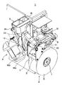
図1は、本発明の第1実施形態にかかる包装装置1を示す。この包装装置1は、錠剤および散薬を処方に応じて1回服用分づつ包装する薬剤包装装置に取り付けられるものである。包装装置1は、シート供給部2と、被包装物導入部としてのホッパー3と、シール部4とからなっている。
【0020】
シート供給部2は、予め長手方向に2つ折りされた細長い包装シート5を巻回したロール6を着脱可能に支持するロール軸7と、前記ロール6から上方に引き出された包装シート5を略水平に方向変換する第1ローラ8と、該第1ローラ8を通過した包装シート5を折り返して略水平方向に導く第2ローラ9と、該第2ローラ9を通過した包装シート5を上方に方向変換する第3ローラ10と、該第3ローラ10を通過した包装シート5を斜め下方に方向変換する第4ローラ11からなっている。前記第2ローラ9と第3ローラ10の間を通過する包装シート5の上方には、当該包装シート5に患者名、服用時期等の情報を印刷するプリンタ12が配設されている。第4ローラ11により斜め下方に方向変換される包装シート5はその折り目が下になるように供給される。第4ローラ11の外周面の上半分を覆うようにカバー11aが設けられ、これにより上流側の包装シート5が惰性で弛んで第4ローラ11との接触部がずれるのを防止するようになっている。
【0021】
ホッパー3は、図示しない薬剤供給部から1回服用分の散薬、錠剤等の薬剤を受け入れて、該薬剤を前記シート供給部2から供給される包装シート5に導入するものである。ホッパー3は、合成樹脂からなり、出口には前記包装シート5の開口に挿入されるノズル13を有している。ホッパー3の外面には取手14が取り付けられ、フレーム15に着脱可能になっている。
【0022】
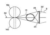
シール部4は、図2,図3に示すように、互いに接して同期回転可能に支持された1対のヒーターローラ16a,16bからなっている。各ヒーターローラ16a,16bは、両側端面に縦シール用の加熱面17を有する中間部18と、該中間部18の上端にあって外周に横シール用の加熱面19を有する上ローラ部20と、前記中間部18の下端にあって前記上ローラ部20と同一形状の下ローラ部21とからなっている。この1対のヒーターローラ16a,16bの間に前記シート供給部2から供給される包装シート5が通過して、上ローラ部20の横シール用加熱面19により包装シート5の開口縁を長手方向にシールするとともに、中間部18の縦シール用加熱面17により当該包装シート5を横切るように開口縁から折り目までをシールして、前記ホッパー3により導入された薬剤を閉じ込めるようになっている。
【0023】
前記ホッパー3のノズル13と前記シート供給部2の第4ローラ11との間には、金属製の三角板22が配設されている。この三角板22は、図4に示すように、2つ折りされた包装シート5の重ね合わせ部にその頂部を挿入されて、該包装シート5を略V字型に開口するようになっている。三角板22の斜辺をなす両側の縁には略半円形の押圧部23が設けられている。これらの押圧部23の位置は、開口された包装シート5の開口縁の近傍、具体的には包装シート5の横シールされる部分(横シール部27)よりやや下方で、包装シート5の内面に内側から接触するような位置である。三角板22は、上端部に耳部24を有し、該耳部24に形成した長孔25にねじ26を挿通してフレーム15にねじ込むことで、上下方向に移動可能で、かつ、ねじ26を中心に回動可能に取り付けられている。なお、三角板22の取り付け方法は、任意であり、図2に示すねじ止めは一例にすぎない。また、押圧部23の形状は、図4に示すような半円形に限らず、台形や三角形とすることもできるし、図5に示すように球体とすることもできる。
【0024】
次に、前記構成からなる包装装置1の動作について説明する。
【0025】
まず、図1に示すように、シート供給部2のロール軸7に包装シート5のロール6を取り付け、該包装シート5の先端を、図1において2点鎖線で示すように、第1ローラ8から第4ローラ11まで導き、シール部4の1対のヒーターローラ16a,16b間に挿入する。次に、三角板22を包装シート5の中に挿入し、ホッパー3を取りつけてそのノズル13を包装シート5の中に挿入する。
【0026】
ヒーターローラ16a,16bを回転駆動すると、ロール6から包装シート5が順次繰り出される。シート供給部2の第4ローラ11から斜め下方に方向変換された包装シート5は、三角板22によって開口される。ホッパー3に供給された1回服用分の薬剤はノズル13を通って包装シート5の内部に導入される。次に、ヒーターローラ16a,16bの横シール用加熱面19により包装シート5の開口の縁部がシールされ、続いて縦シール用加熱面17により包装シート5の開口から折り目までがシールされる。これにより、図2に示すように、薬剤は1つの横シール部27と2つの縦シール部28と折り目29によって囲まれて封じ込められる。このように、1回服用分の薬剤が順次包装され、包装シート5は包装帯30となって斜め下方に排出される。
【0027】
ヒーターローラ16a,16bにより包装シート5をシールする前に、包装シート5の横シールされる部分のやや下方の部分が三角板22の押圧部23によって内側から接触して押圧されるので、包装シート5の横シールが行なわれる部分と縦シールが行われる部分との張力の差が無くなり、皺の発生が防止される。なお、皺が依然として発生する場合は、三角板22の上下位置または角度を微調整することで、押圧部23を皺が発生しないような位置に変更することができる。
【0028】
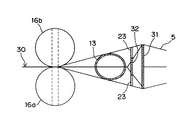
図6,図7は、本発明の第2の実施形態を示す。この実施形態では、図8(a)に示すように三角板31の両側縁には図4のような押圧部23を設けない代わりに、図8(b)に示すような別部材の皺抑え板32を三角板31に取り付けている。皺抑え板32は、逆T字形で、両端に押圧部23が形成されている。皺抑え板32は、上端部に耳部33を有し、該耳部33に形成した孔34に図6に示すようにねじ35を挿通して、前記三角板31に設けた支持片36に取り付けることで、ねじ35を中心に回動可能になっている。なお、皺抑え板32の取り付け方法は、任意であり、図6に示すねじ止めは一例にすぎない。また、皺抑え板32は、三角板31に取り付けないで、図2に示す前記実施形態の三角板22のようにフレーム15に取り付けてもよい。
【0029】
また、図6では、皺抑え板32は、三角板31から離間するように取りつけているが、図9に示すように、三角板31に接触させてガイド37に沿って上下方向にスライドするように取り付けるとともに、長孔38にねじ39を挿通して三角板31に固定するようにしてもよい。さらに、図10に示すように、ガイド40に沿って水平方向にスライド可能な一対の皺抑え板41a,41bを設けるとともに、両皺抑え板41a,41bに互いに対向するように形成したラック42と噛合するピニオン43を設けて、押圧部23の突出量を調整できるようにしてもよい。
【0030】
この第2実施形態においても、前記第1実施形態と同様に、皺抑え板41a,41bの押圧部23により、ヒーターローラ16a,16bによる包装シート5のシール時に、皺の発生が防止される。また、必要に応じて、図6の場合は皺抑え板32の押圧部23の角度、図9の場合は皺抑え板32の押圧部23の上下位置、図10の場合は皺抑え板41a,41bの押圧部23の突出量をそれぞれ変更することができる。
【0031】
なお、皺抑え板32,41a,41bの位置は、図6では三角板31に対して包装シート5の供給方向の下流側であるが、上流側でもよい。また、ノズル13の下流側、すなわち、ノズル13とヒーターローラ16a,16bの間でもよい。要するに、シート供給部2の第4ローラ11からシール部4であるヒーターローラ16a,16bまでの間、好ましくは第4ローラ11からホッパー3のノズル13までの間に配置すればよい。
【0032】
図11,図12は、本発明の第3実施例を示す。この実施形態では、前記第1実施例や第2実施例のような三角板22,31が設けられていない。包装シート5の開口はホッパー3のノズル13によって行われるようになっている。そして、このホッパー3のノズル13の外面に、開口された包装シート5に内側から接触するように、押圧部23が設けられている。この押圧部23は、ノズル13と一体に成形されてもよいが、図9や図10のような押圧部23を有する皺抑え部材32、41a,41bを上下方向または水平方向にスライド可能に取り付けるようにしてもよい。この押圧部23の存在により、前記第1,第2実施形態と同様に、ヒーターローラ16a,16bによる包装シート5のシール時に、皺の発生が防止される。そして、図9や図10の場合は、必要に応じて、押圧部23の上下位置または水平位置を変更することができる。
【0033】
前記第3実施形態では、ホッパー3のノズル13の上流側に、包装シート5を挟持可能な挟持ユニット50が配設されている。この挟持ユニット50は、図13に示すように、L字形の1対の挟持片51a,51bをピン52により回動可能に基板53に取り付けたものである。各挟持片51a,51bの先端の対向部分にはパッド54が取り付けられ、基端にはピン52を中心とするセグメントギヤ55a,55bが形成されている。各挟持片51a,51bのセグメントギヤ55a,55bは互いに噛合している。一方の挟持片51bには駆動レバー56が延設され、この駆動レバー56をピン52を中心に矢印方向に回動させると挟持片51a,51bが開き、駆動レバー56を戻すと挟持片51a,51bが閉じて包装シート5をその折り目側から挟持するようになっている。
【0034】
前記挟持ユニット50は、包装シート5の移動中は開いており、包装シート5が停止してホッパー3のノズル13から薬剤が導入されるときに閉じる。これにより、ノズル13から導入されて包装シート5に落下する際に、薬剤がノズル13より上流側に飛散して、次に包装される薬剤に混入するのが防止される。
【0035】
前記挟持ユニット50は、図2に示す第1実施形態、図6に示す第2実施形態において、三角板22,31の上流側に設けてもよい。これにより、ホッパー3のノズル13から導入される薬剤が三角板22,31から上流側へ飛散するのが防止されるので、次に包装される薬剤が汚染されることがない。また、シール不良も防止される。
【0036】
前記挟持ユニット50が存在すると、最初に包装シート5をセットする際に挟持ユニット50の近傍で包装シート5を通しにくくなる。そこで、包装シート5を通し易くするために、図14から図16に示すような構造の挟持ユニット50´を採用することができる。この挟持ユニット50´において、装置の手前側にある第1挟持片51aは、挟持面にネオプレンスポンジからなる平面状のパッド54aを有するアーム57と、セグメントギヤ55aを有するアームベース58とからなり、このアーム57とアームベース58は重ねられてピン52により基板53に回動可能に取り付けられている。アーム57には、アームベース58に向かって図示しないバネにより突出するボールプランジャ59が設けられ、該ボールプランジャ59は、アームベース58に形成された凹部60に係脱可能になっている。一方、装置の奥側にある第2挟持片51bは図13に示す前記実施形態と同様であるが、パッド54bの形状は、第1挟持片51aのパッド54aのように平面ではなく、図14(b)に示すように、ノズル13に近接し、かつ、ノズル13の軸に平行に延びる垂直部54bVと、該垂直部54bVの両端から水平に延びる水平部54bHとからなるコ字形になっている。第1挟持片51aのアームベース58と第2挟持片51bとの間には、バネ61が取り付けられ、第1挟持片51aと第2挟持片51bを開いた状態に維持している。
【0037】
このような構造の挟持ユニット50´では、図15に示すように、第1挟持片51aと第2挟持片51bが開いた状態から駆動レバー56を反時計回りに回動すると、バネ61の付勢力に抗して第1挟持片51aと第2挟持片51bが閉じ、第1挟持片51aのアーム57の平面状のパッド54aと第2挟持片51bの横向きU字形のパッド54bとで包装シート5を挟持する。これにより、薬剤が上流側へ吹き上がるのが防止される。特に、図14(b)に示すように、第2挟持片51bのパッド54bの垂直部54bVが、ノズル13の近傍で、第1挟持片51aのパッド54aに面接触でなく線接触して包装シート5を挟持するので、薬剤がノズルと挟持ユニット50´の間からすり抜けるのを確実に防止することができる。
【0038】
図15に示すように、第1挟持片51aと第2挟持片51bが開いた状態で第1挟持片51aのアーム57を手前側に引くと、図16に示すように、アーム57のボールプランジャ59がアームベース58の凹部60から脱出して、アーム57がピン52を中心に手前側に倒れるので、第1挟持片51aと第2挟持片51bの間に包装シート5を簡単に通すことができる。
【0039】
なお、前記挟持ユニット50、50´において、第1挟持片51aのパッド54aと第2挟持片51bのパッド54bは、いずれも弾性体としたが、いずれか一方を鉄やステンレス鋼のような剛性体とし、他方を弾性体としてもよい。また、前記挟持ユニット50´において、第2挟持片51bのパッド54bの形状としては、前述のコ字形に限らず、少なくとも1つの垂直部54bVがノズル13に近接し、かつ、ノズル13の軸に平行に延びていればよく、例えば、I字形、H形、E形、F形、L形、□形等の形状を採用することができる。
【0040】
以上の実施形態では、三角板22,31として金属製の板状のものを用いたが、図17,18に示すように、これらの代わりに合成樹脂からなるブロック状の三角体62を使用してもよい。この三角体62は、下部が逆三角形になった板状の基部63と、該基部63の略下半分から突出する略三角錐形のブロック部64とからなっている。ブロック部64は中空に成形されている。ブロック部64の上面は蓋64aで閉じてもよいが、開放したままにしておけば、飛散した薬剤をブロック部64の内部に溜めて、次の包装への混入を防止することができる。三角体62には、基部63の両側縁からブロック部64の斜面に沿って延び、かつ、僅かに外側に隆起する本発明の押圧部65が形成されている。基部63の下端からブロック部64の斜面に沿って稜線66が延び、該稜線66の両側に斜面がV字形に形成されている。この三角体66は、図19に示すように、基部63の上端に取り付けた金具67により図2の第1実施形態と同様にフレーム15に取り付け、ブロック部64がノズル13と反対側に向き、かつ、稜線66が包装シート5の折目に沿うように調整する。この三角体62の押圧部65により、ヒーターローラ16a,16bによる包装シート5のシール時に、包装シート5に皺が発生するのが防止される。また、ブロック部64の稜線により、2点鎖線で示すように、包装シート5の折目部分に弛み68が発生するのが防止される。
【0041】
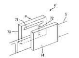
また、以上の実施形態では、ヒーターローラ16a,16bからなるシール部4を使用したが、本発明の構成要素であるシール部はこれに限定されるものではなく、図20に示すような所謂パック式のシール部4´でもよい。このシール部4´は、横シール用加熱面71と縦シール用加熱面72とを配設した矢印方向に移動可能な可動プレート73と、前記加熱面71,72に対応する部分に図示しないスポンジを設けた固定プレート74とで包装シート5を挟むことで、横シールと縦シールを同時に行う。
【0042】
また、前記実施形態では、シート供給部は、第1ローラ8から第4ローラ11を使用して方向変換させたが、方向変換させずにロール6から真直ぐにホッパー3およびヒーターローラ16a,16bに向かって供給するようにしてもよい。
【0043】
【発明の効果】
以上の説明から明らかなように、本発明によれば、シート供給部とシール部の間で、包装シートの開口の縁部近傍に内側から接触する押圧部を設けたので、包装シートの横シールが行なわれる部分と縦シールが行われる部分との張力の差が無くなり、皺の発生が防止される。この結果、見栄えがよく、切断し易い包装帯を提供することができる。
【0044】
被包装物導入部は包装シートの開口に挿入されるノズルを有するホッパーからなり、押圧部はホッパーのノズルの外面に設けたので、押圧部を設けるための新たな部材を取り付ける必要がなくなる。
【0045】
シート供給部と被包装物導入部の間でシートを略V字型に開口する三角部材を配設したので、包装シートに十分な開口を形成することができ、被包装物の導入がスムーズに行える。また、三角部材により開口部が仕切られるので、導入した被包装物が三角部材から包装シートの供給方向上流側へ飛散するのが防止される。
【0046】
三角部材を三角板とし、該三角板の側縁に押圧部を設けたので、押圧部を設けるための新たな部材を取り付ける必要がなくなる。
【0047】
三角板は、開口の縁部から押圧部までの距離を調整できるように移動可能にしたので、実際の皺の発生状況を見て押圧部の位置を微調整することができる。
【0048】
被包装物導入部と三角板との間、またはシート供給部と三角板との間で、包装シートの開口内に皺抑え板を設け、該皺抑え板の側縁に押圧部を設けたので、皺の発生状況を見て、皺抑え板だけを効果的な位置に設けることができる。
【0049】
皺抑え板は、開口の縁部から押圧部までの距離を調整できるように移動可能にしたので、実際の皺の発生状況を見て押圧部の位置を微調整することができる。
【0050】
三角部材をブロック状の三角体とし、基部の両側縁からブロック体の斜面に沿って延びるように押圧部を設けたので、この広範囲の押圧部により皺の発生を効果的に防止することができる。また、基部の下端からブロック部の斜面に沿って延びる稜線が包装シートの折目に沿うようにしたので、包装シートの折目部分に弛みが発生するのを防止できる。
【図面の簡単な説明】
【図1】 本発明の第1実施形態にかかる包装装置を示す斜視図。
【図2】 図1の包装装置の概略正面図。
【図3】 図2の包装装置のIII方向から見た矢視図。
【図4】 三角板の正面図。
【図5】 三角板の変形例を示す正面図。
【図6】 本発明の第2実施形態にかかる包装装置の概略正面。
【図7】 図5の包装装置のVII方向から見た矢視図。
【図8】 (a)は三角板、(b)は皺抑え板のそれぞれ正面図。
【図9】 皺抑え板を取り付けた三角板の変形例を示す正面図。
【図10】 皺抑え板を取り付けた三角板のさらなる変形例を示す正面図。
【図11】 本発明の第3実施形態にかかる包装装置の概略正面。
【図12】 図9の包装装置のXII方向から見た矢視図。
【図13】 挟持装置の正面図。
【図14】 挟持装置の他の例を示す斜視図(a)と、その挟持装置を使用した部分正面図(b)。
【図15】 図14の挟持装置の正面図。
【図16】 図14の挟持装置の第1挟持片のアームを引き倒した状態を示す正面図。
【図17】 三角体の斜視図。
【図18】 図17の三角体の(a)は側面図、(b)は正面図。
【図19】 図17の三角体を取り付けた包装装置の概略正面図。
【図20】 パック式のヒートシール装置の斜視図。
【図21】 従来の包装装置の概略正面。
【図22】 図21の包装装置のXXII方向から見た矢視図。
【符号の説明】
1 包装装置
2 シート供給部
3 ホッパー(被包装物導入部)
4 シール部
5 包装シート
13 ノズル
16a,16b ヒーターローラ
22 三角板
23,65 押圧部
31 三角板
32 皺抑え板
41a,41b 皺抑え板
62 三角体
65 押圧部
66 稜線[0001]
BACKGROUND OF THE INVENTION
The present invention relates to a packaging device for packaging an object to be packaged such as a tablet or powder.
[0002]
[Prior art]
2. Description of the Related Art Conventionally, various types of drug packaging devices have been provided for packaging drugs such as tablets and powders in a single dose based on a prescription. Among them, there is one that uses a roll in which an elongated packaging sheet that is folded in advance in the longitudinal direction is wound.
[0003]
In this apparatus, as shown in FIGS. 21 and 22, a
[0004]
The
[0005]
[Problems to be solved by the invention]
This invention is made | formed in view of the said conventional problem, and makes it a subject to provide the packaging apparatus which a wrinkle does not generate | occur | produce in a packaging sheet.
[0006]
[Means for Solving the Problems]
In order to solve the above problems, the present invention provides a sheet supply unit that supplies an elongated packaging sheet folded in advance in the longitudinal direction, and the packaging sheet supplied from the sheet supply unit is opened and covered from the opening. wherein the articles to be packaged introducing portion for introducing the packages in a packaging apparatus that includes a seal portion for sealing said packaging sheet introduced the material to be packaged in the closed Ji write Mel so, and the sheet feeding unit seal A pressing portion that acts outward from the inside is provided near the edge of the opening of the packaging sheet.
[0007]
In the invention comprising the above means, since the pressing portion contacts and presses the vicinity of the edge of the opening of the packaging sheet from the inside, the difference in tension between the portion where the packaging sheet is laterally sealed and the portion where the longitudinal sealing is performed Is eliminated, and the generation of wrinkles is prevented.
[0008]
The packaged article introduction part is composed of a hopper having a nozzle inserted into the opening of the packaging sheet, and the pressing part can be provided on the outer surface of the nozzle of the hopper.
[0009]
A triangular member that opens the sheet in a substantially V shape may be disposed between the sheet supply unit and the article introduction unit.
[0010]
The triangular member may be a triangular plate. In this case, it is preferable to provide the pressing portion on a side edge of the triangular plate.
[0011]
It is preferable that the triangular plate is movable so that the distance from the edge of the opening to the pressing portion can be adjusted.
[0012]
Between the packaged article introduction part and the triangular plate, or between the sheet supply unit and the triangular plate, a wrinkle holding plate is provided in the opening of the packaging sheet, and the pressing portion is provided on a side edge of the wrinkle holding plate. Can also be provided.
[0013]
It is preferable that the wrinkle holding plate is movable so that the distance from the edge of the opening to the pressing portion can be adjusted.
[0014]
The triangular member may be a block-shaped triangular body. The triangular body preferably includes a plate-like base portion whose lower portion is formed in an inverted triangle and a substantially triangular pyramidal block portion protruding from the lower half of the base portion. In this case, it is preferable that the pressing portion is provided so as to extend from both side edges of the base portion along the slope of the block body. Moreover, it is preferable that the ridgeline extended along the slope of a block part from the lower end of the said base follows a fold of the said packaging sheet.
[0015]
The packaged article introduction part is composed of a hopper having a nozzle inserted into the opening of the packaging sheet, and is provided with a sandwiching unit comprising a pair of sandwiching pieces capable of sandwiching the packaging sheet on the upstream side of the nozzle. It is preferable to close the pair of sandwiching pieces when the object is introduced. Thereby, it can prevent that a to-be-packaged object slips through between a nozzle and a clamping unit.
[0016]
The pair of sandwiching pieces are provided so as to be openable and closable by segment gears meshing with each other, and one of the pair of sandwiching pieces includes an arm and an arm base having a segment gear. It is preferable that the arm base is pivotably attached and falls when the arm is pulled with the pair of holding pieces open. Thereby, a packaging sheet can be easily passed between a pair of clamping pieces.
[0017]
It is preferable that the pair of sandwiching pieces have a pad at a tip-facing portion, and one pad has a vertical portion that is close to the nozzle and extends in parallel with the axis of the nozzle. Thereby, since the vertical part of one pad and the other pad line-contact and pinch | wrap a packaging sheet, it can prevent reliably that a to-be-packaged object slips through between a nozzle and a clamping unit.
[0018]
DETAILED DESCRIPTION OF THE INVENTION
Hereinafter, embodiments of the present invention will be described with reference to the accompanying drawings.
[0019]
FIG. 1 shows a
[0020]
The sheet supply unit 2 includes a roll shaft 7 that removably supports a
[0021]
Hopper 3 is for the powdered medicine one time dose amount from a drug supply unit (not shown), receives an agent such as tablets, introducing agent to the
[0022]
As shown in FIGS. 2 and 3, the
[0023]
Between the
[0024]
Next, operation | movement of the
[0025]
First, as shown in FIG. 1, the
[0026]
When the
[0027]
Before the
[0028]
6 and 7 show a second embodiment of the present invention. In this embodiment, instead of providing the
[0029]
Further, in FIG. 6, the
[0030]
Also in the second embodiment, generation of wrinkles is prevented when the
[0031]
In addition, although the position of the
[0032]
11 and 12 show a third embodiment of the present invention. In this embodiment, the
[0033]
In the third embodiment, the clamping
[0034]
The clamping
[0035]
The clamping
[0036]
When the clamping
[0037]
In the holding
[0038]
As shown in FIG. 15, when the
[0039]
In the sandwiching
[0040]
In the above embodiment, the
[0041]
Further, in the above embodiment, the heater roller 16a, but using a
[0042]
In the above embodiment, the sheet supply unit has changed the direction using the first roller 8 to the
[0043]
【The invention's effect】
As is clear from the above description, according to the present invention, since the pressing portion that comes in contact with the inside of the edge of the opening of the packaging sheet is provided between the sheet supply portion and the sealing portion, the lateral seal of the packaging sheet There is no difference in tension between the portion where the sealing is performed and the portion where the vertical sealing is performed, and wrinkles are prevented from occurring. As a result, it is possible to provide a packaging band that looks good and is easy to cut.
[0044]
Since the packaged article introduction portion is composed of a hopper having a nozzle inserted into the opening of the packaging sheet, and the pressing portion is provided on the outer surface of the nozzle of the hopper, it is not necessary to attach a new member for providing the pressing portion.
[0045]
Since the triangular member that opens the sheet in a substantially V shape is disposed between the sheet supply unit and the packaged article introducing unit, a sufficient opening can be formed in the packaging sheet, and the introduction of the packaged article is smooth Yes. Moreover, since the opening is partitioned by the triangular member, the introduced article to be packaged is prevented from scattering from the triangular member to the upstream side in the supply direction of the packaging sheet.
[0046]
Since the triangular member is a triangular plate and the pressing portion is provided on the side edge of the triangular plate, it is not necessary to attach a new member for providing the pressing portion.
[0047]
Since the triangular plate is movable so that the distance from the edge of the opening to the pressing portion can be adjusted, the position of the pressing portion can be finely adjusted by looking at the actual state of occurrence of wrinkles.
[0048]
Since the wrinkle restraining plate is provided in the opening of the packaging sheet between the article introduction portion and the triangular plate or between the sheet supply portion and the triangular plate, the pressing portion is provided on the side edge of the wrinkle restraining plate. In view of the occurrence of this, only the wrinkle control plate can be provided at an effective position.
[0049]
Since the wrinkle holding plate is movable so that the distance from the edge of the opening to the pressing portion can be adjusted, the position of the pressing portion can be finely adjusted by looking at the actual occurrence state of wrinkles.
[0050]
Since the triangular member is a block-shaped triangular body and the pressing portions are provided so as to extend along the slopes of the block body from both side edges of the base portion, the wide range of pressing portions can effectively prevent the generation of wrinkles. . In addition, since the ridge line extending from the lower end of the base portion along the slope of the block portion is along the fold of the packaging sheet, it is possible to prevent the fold portion of the packaging sheet from being loosened.
[Brief description of the drawings]
FIG. 1 is a perspective view showing a packaging device according to a first embodiment of the present invention.
FIG. 2 is a schematic front view of the packaging device of FIG.
3 is an arrow view of the packaging device of FIG. 2 as viewed from the III direction.
FIG. 4 is a front view of a triangular plate.
FIG. 5 is a front view showing a modification of the triangular plate.
FIG. 6 is a schematic front view of a packaging device according to a second embodiment of the present invention.
7 is an arrow view of the packaging device of FIG. 5 as seen from the VII direction.
8A is a front view of a triangular plate, and FIG. 8B is a front view of a wrinkle holding plate.
FIG. 9 is a front view showing a modification of the triangular plate to which the heel restraining plate is attached.
FIG. 10 is a front view showing a further modification of the triangular plate to which the heel restraining plate is attached.
FIG. 11 is a schematic front view of a packaging device according to a third embodiment of the present invention.
12 is an arrow view of the packaging device of FIG. 9 as seen from the XII direction.
FIG. 13 is a front view of the holding device.
FIG. 14 is a perspective view (a) showing another example of the clamping device, and a partial front view (b) using the clamping device.
15 is a front view of the clamping device of FIG. 14;
16 is a front view showing a state in which the arm of the first clamping piece of the clamping device of FIG. 14 is pulled down. FIG.
FIG. 17 is a perspective view of a triangular body.
18A is a side view, and FIG. 18B is a front view of the triangular body of FIG.
19 is a schematic front view of a packaging device to which the triangular body of FIG. 17 is attached.
FIG. 20 is a perspective view of a pack-type heat seal device.
FIG. 21 is a schematic front view of a conventional packaging device.
22 is an arrow view of the packaging device of FIG. 21 as seen from the XXII direction.
[Explanation of symbols]
1 wrapping apparatus 2 sheet feeding unit 3 hopper (packaged articles introducing portion)
4 Sealing
Claims (15)
該シート供給部から供給される前記包装シートを開口してその開口から被包装物を導入する被包装物導入部と、
導入された前記被包装物を閉じ込めるように前記包装シートをシールするシール部とを備えた包装装置において、
前記シート供給部と前記シール部の間で、前記包装シートの開口の縁部近傍に内側から外方向に作用する突出した押圧部を設けたことを特徴とする包装装置。A sheet supply unit for supplying an elongated packaging sheet folded in advance in the longitudinal direction;
A packaged article introduction unit that opens the packaging sheet supplied from the sheet supply unit and introduces a packaged article from the opening;
In a packaging device including a seal portion that seals the packaging sheet so as to confine the introduced article to be packaged,
A packaging device, wherein a protruding pressing portion acting outward from the inside is provided in the vicinity of the edge of the opening of the packaging sheet between the sheet supply portion and the seal portion.
Priority Applications (3)
| Application Number | Priority Date | Filing Date | Title |
|---|---|---|---|
| JP2003081632A JP4343565B2 (en) | 2002-10-18 | 2003-03-24 | Packaging equipment |
| KR1020030070477A KR101061732B1 (en) | 2002-10-18 | 2003-10-10 | Packing device |
| TW093100467A TWI308125B (en) | 2002-10-18 | 2004-01-08 | Packing apparatus |
Applications Claiming Priority (2)
| Application Number | Priority Date | Filing Date | Title |
|---|---|---|---|
| JP2002305183 | 2002-10-18 | ||
| JP2003081632A JP4343565B2 (en) | 2002-10-18 | 2003-03-24 | Packaging equipment |
Publications (3)
| Publication Number | Publication Date |
|---|---|
| JP2004189336A JP2004189336A (en) | 2004-07-08 |
| JP2004189336A5 JP2004189336A5 (en) | 2007-05-10 |
| JP4343565B2 true JP4343565B2 (en) | 2009-10-14 |
Family
ID=32774449
Family Applications (1)
| Application Number | Title | Priority Date | Filing Date |
|---|---|---|---|
| JP2003081632A Expired - Fee Related JP4343565B2 (en) | 2002-10-18 | 2003-03-24 | Packaging equipment |
Country Status (3)
| Country | Link |
|---|---|
| JP (1) | JP4343565B2 (en) |
| KR (1) | KR101061732B1 (en) |
| TW (1) | TWI308125B (en) |
Families Citing this family (5)
| Publication number | Priority date | Publication date | Assignee | Title |
|---|---|---|---|---|
| JP4936038B2 (en) * | 2005-08-04 | 2012-05-23 | 株式会社湯山製作所 | Drug packaging device |
| JP4220568B2 (en) | 2007-04-02 | 2009-02-04 | 株式会社湯山製作所 | Drug packaging device |
| JP5294776B2 (en) * | 2008-09-22 | 2013-09-18 | 高園産業株式会社 | Paper gripping unit of the packaging device |
| JP4469007B2 (en) | 2008-10-02 | 2010-05-26 | 株式会社湯山製作所 | Drug packaging device |
| CN105253656A (en) * | 2015-10-19 | 2016-01-20 | 任一平 | Bag moving mechanism for automatic compound bag production device |
Family Cites Families (1)
| Publication number | Priority date | Publication date | Assignee | Title |
|---|---|---|---|---|
| JPH0242561Y2 (en) * | 1985-11-20 | 1990-11-14 |
-
2003
- 2003-03-24 JP JP2003081632A patent/JP4343565B2/en not_active Expired - Fee Related
- 2003-10-10 KR KR1020030070477A patent/KR101061732B1/en active IP Right Grant
-
2004
- 2004-01-08 TW TW093100467A patent/TWI308125B/en not_active IP Right Cessation
Also Published As
| Publication number | Publication date |
|---|---|
| TW200508093A (en) | 2005-03-01 |
| JP2004189336A (en) | 2004-07-08 |
| KR101061732B1 (en) | 2011-09-02 |
| KR20040034409A (en) | 2004-04-28 |
| TWI308125B (en) | 2009-04-01 |
Similar Documents
| Publication | Publication Date | Title |
|---|---|---|
| JP5684645B2 (en) | Bag making and packaging machine | |
| JP2012236620A5 (en) | ||
| JP4343565B2 (en) | Packaging equipment | |
| TW201021786A (en) | Medication packaging device | |
| JP2008094456A (en) | Vertical seal mechanism | |
| JP2709836B2 (en) | Method and apparatus for continuously forming bubble cushioning material for packing | |
| KR101020276B1 (en) | Medicine packing apparatus | |
| US10822127B2 (en) | Packaging apparatus | |
| JP6689586B2 (en) | Packaging equipment | |
| CN207389751U (en) | A kind of double aluminium packing machine packs jet printing appts | |
| JP4565899B2 (en) | Bag making and packaging machine | |
| JP2005119185A (en) | Bag making apparatus having streak forming mechanism | |
| JP5294776B2 (en) | Paper gripping unit of the packaging device | |
| JP2557370Y2 (en) | Antistatic guide device for packaging sheets in a packaging machine | |
| JP4336518B2 (en) | Rotary automatic packaging machine | |
| JP5666943B2 (en) | Stretch packaging equipment | |
| JP6689587B2 (en) | Packaging equipment | |
| JP3908044B2 (en) | Bag mouth folding device in packaging machine | |
| JP6754179B2 (en) | Drug packaging equipment | |
| JPS5924643Y2 (en) | filling packaging equipment | |
| JP2010235172A (en) | Packaging device and medicine part packaging device for medicine | |
| JP2005289497A (en) | Mechanism for adjusting position between top sealing rolls in rotary automatic packaging machine | |
| JP2010235170A (en) | Packaging apparatus and medicine separately packaging device | |
| JP4178828B2 (en) | Film packaging equipment | |
| JP2004115131A (en) | Medicine packaging apparatus |
Legal Events
| Date | Code | Title | Description |
|---|---|---|---|
| A521 | Request for written amendment filed |
Free format text: JAPANESE INTERMEDIATE CODE: A523 Effective date: 20060302 |
|
| A621 | Written request for application examination |
Free format text: JAPANESE INTERMEDIATE CODE: A621 Effective date: 20060302 |
|
| A521 | Request for written amendment filed |
Free format text: JAPANESE INTERMEDIATE CODE: A523 Effective date: 20070320 |
|
| A977 | Report on retrieval |
Free format text: JAPANESE INTERMEDIATE CODE: A971007 Effective date: 20081006 |
|
| A131 | Notification of reasons for refusal |
Free format text: JAPANESE INTERMEDIATE CODE: A131 Effective date: 20090120 |
|
| A521 | Request for written amendment filed |
Free format text: JAPANESE INTERMEDIATE CODE: A523 Effective date: 20090302 |
|
| TRDD | Decision of grant or rejection written | ||
| A01 | Written decision to grant a patent or to grant a registration (utility model) |
Free format text: JAPANESE INTERMEDIATE CODE: A01 Effective date: 20090609 |
|
| A01 | Written decision to grant a patent or to grant a registration (utility model) |
Free format text: JAPANESE INTERMEDIATE CODE: A01 |
|
| A61 | First payment of annual fees (during grant procedure) |
Free format text: JAPANESE INTERMEDIATE CODE: A61 Effective date: 20090709 |
|
| FPAY | Renewal fee payment (event date is renewal date of database) |
Free format text: PAYMENT UNTIL: 20120717 Year of fee payment: 3 |
|
| R150 | Certificate of patent or registration of utility model |
Ref document number: 4343565 Country of ref document: JP Free format text: JAPANESE INTERMEDIATE CODE: R150 Free format text: JAPANESE INTERMEDIATE CODE: R150 |
|
| FPAY | Renewal fee payment (event date is renewal date of database) |
Free format text: PAYMENT UNTIL: 20120717 Year of fee payment: 3 |
|
| FPAY | Renewal fee payment (event date is renewal date of database) |
Free format text: PAYMENT UNTIL: 20130717 Year of fee payment: 4 |
|
| R250 | Receipt of annual fees |
Free format text: JAPANESE INTERMEDIATE CODE: R250 |
|
| R250 | Receipt of annual fees |
Free format text: JAPANESE INTERMEDIATE CODE: R250 |
|
| R250 | Receipt of annual fees |
Free format text: JAPANESE INTERMEDIATE CODE: R250 |
|
| R250 | Receipt of annual fees |
Free format text: JAPANESE INTERMEDIATE CODE: R250 |
|
| R250 | Receipt of annual fees |
Free format text: JAPANESE INTERMEDIATE CODE: R250 |
|
| R250 | Receipt of annual fees |
Free format text: JAPANESE INTERMEDIATE CODE: R250 |
|
| R250 | Receipt of annual fees |
Free format text: JAPANESE INTERMEDIATE CODE: R250 |
|
| R250 | Receipt of annual fees |
Free format text: JAPANESE INTERMEDIATE CODE: R250 |
|
| R250 | Receipt of annual fees |
Free format text: JAPANESE INTERMEDIATE CODE: R250 |
|
| LAPS | Cancellation because of no payment of annual fees |