JP4339850B2 - Apparatus and method for providing a transmitted multi-carrier signal, and apparatus and method for providing an output signal from a received multi-carrier signal - Google Patents
Apparatus and method for providing a transmitted multi-carrier signal, and apparatus and method for providing an output signal from a received multi-carrier signal Download PDFInfo
- Publication number
- JP4339850B2 JP4339850B2 JP2005503814A JP2005503814A JP4339850B2 JP 4339850 B2 JP4339850 B2 JP 4339850B2 JP 2005503814 A JP2005503814 A JP 2005503814A JP 2005503814 A JP2005503814 A JP 2005503814A JP 4339850 B2 JP4339850 B2 JP 4339850B2
- Authority
- JP
- Japan
- Prior art keywords
- signal
- received
- signals
- carrier frequency
- carrier
- Prior art date
- Legal status (The legal status is an assumption and is not a legal conclusion. Google has not performed a legal analysis and makes no representation as to the accuracy of the status listed.)
- Expired - Lifetime
Links
- 238000000034 method Methods 0.000 title claims description 33
- 230000005540 biological transmission Effects 0.000 claims description 30
- 230000003595 spectral effect Effects 0.000 claims description 16
- 238000012545 processing Methods 0.000 claims description 10
- 238000004590 computer program Methods 0.000 claims description 5
- 238000006243 chemical reaction Methods 0.000 claims description 4
- 238000001228 spectrum Methods 0.000 claims description 3
- 230000000737 periodic effect Effects 0.000 description 34
- 230000000875 corresponding effect Effects 0.000 description 29
- 230000002596 correlated effect Effects 0.000 description 17
- 238000010586 diagram Methods 0.000 description 13
- 238000005562 fading Methods 0.000 description 12
- 238000005314 correlation function Methods 0.000 description 10
- 125000004122 cyclic group Chemical group 0.000 description 10
- 230000004044 response Effects 0.000 description 9
- 238000004891 communication Methods 0.000 description 8
- 239000011159 matrix material Substances 0.000 description 8
- 230000010363 phase shift Effects 0.000 description 7
- 238000012958 reprocessing Methods 0.000 description 7
- 239000000969 carrier Substances 0.000 description 6
- 238000012937 correction Methods 0.000 description 4
- 230000001934 delay Effects 0.000 description 4
- 238000001514 detection method Methods 0.000 description 4
- 230000008901 benefit Effects 0.000 description 3
- 230000003111 delayed effect Effects 0.000 description 3
- 230000000694 effects Effects 0.000 description 3
- 230000003321 amplification Effects 0.000 description 2
- 230000003247 decreasing effect Effects 0.000 description 2
- 238000011156 evaluation Methods 0.000 description 2
- 239000000284 extract Substances 0.000 description 2
- 238000013507 mapping Methods 0.000 description 2
- 238000003199 nucleic acid amplification method Methods 0.000 description 2
- 238000010561 standard procedure Methods 0.000 description 2
- 230000009466 transformation Effects 0.000 description 2
- 230000004075 alteration Effects 0.000 description 1
- 230000002238 attenuated effect Effects 0.000 description 1
- 230000008859 change Effects 0.000 description 1
- 238000013461 design Methods 0.000 description 1
- 230000001627 detrimental effect Effects 0.000 description 1
- 238000001914 filtration Methods 0.000 description 1
- 230000006870 function Effects 0.000 description 1
- 238000007781 pre-processing Methods 0.000 description 1
- 230000008569 process Effects 0.000 description 1
- 230000002441 reversible effect Effects 0.000 description 1
- 238000012549 training Methods 0.000 description 1
- 238000000844 transformation Methods 0.000 description 1
Images


Classifications
-
- H—ELECTRICITY
- H04—ELECTRIC COMMUNICATION TECHNIQUE
- H04L—TRANSMISSION OF DIGITAL INFORMATION, e.g. TELEGRAPHIC COMMUNICATION
- H04L1/00—Arrangements for detecting or preventing errors in the information received
- H04L1/02—Arrangements for detecting or preventing errors in the information received by diversity reception
- H04L1/06—Arrangements for detecting or preventing errors in the information received by diversity reception using space diversity
-
- H—ELECTRICITY
- H04—ELECTRIC COMMUNICATION TECHNIQUE
- H04L—TRANSMISSION OF DIGITAL INFORMATION, e.g. TELEGRAPHIC COMMUNICATION
- H04L5/00—Arrangements affording multiple use of the transmission path
- H04L5/003—Arrangements for allocating sub-channels of the transmission path
- H04L5/0044—Arrangements for allocating sub-channels of the transmission path allocation of payload
Landscapes
- Engineering & Computer Science (AREA)
- Signal Processing (AREA)
- Computer Networks & Wireless Communication (AREA)
- Radio Transmission System (AREA)
Description
本発明は電気通信の分野に関し、特に、ダイバーシチ技術(diversity technique)を用いるマルチキャリア送信方式の分野に関する。 The present invention relates to the field of telecommunications, and in particular to the field of multi-carrier transmission schemes using diversity techniques.
無線通信においては、フェージングの有害な影響を緩和するために送信ダイバーシチ技術が使用される。1つの送信ダイバーシチ技術は、同じ信号が複数のアンテナから異なった遅延で送信されるという遅延ダイバーシチである。これは結果として、各送信アンテナから各受信アンテナまでの本来のサブチャネルと比較する場合、周波数選択性が向上した、従って周波数ダイバーシチが向上した入力チャネルに相当する。直交周波数分割多重化(OFDM)においては、送信機に取り入れられた周波数ダイバーシチを、受信機の中に組み込まれた前進型エラー訂正用デコーダ(forward error correcting decoder)が利用することができる。 In wireless communications, transmit diversity techniques are used to mitigate the detrimental effects of fading. One transmit diversity technique is delay diversity in which the same signal is transmitted from multiple antennas with different delays. This results in an input channel with improved frequency selectivity and therefore improved frequency diversity when compared to the original subchannel from each transmit antenna to each receive antenna. In orthogonal frequency division multiplexing (OFDM), the frequency diversity incorporated in the transmitter can be used by a forward error correcting decoder incorporated in the receiver.
しかしながら、マルチキャリア送信システムの中に別の遅延を取り入れると、これは時間ダイバーシチを実現するために必要とされることが多いが、より長い保護間隔(guard interval)が必要とされ、結果として帯域幅の効率が減少される。この保護間隔が十分に長くない場合は、キャリア間の干渉が発生する可能性がある。しかしながら、保護間隔の長さが増加すると、保護間隔を情報の送信に利用することができないため、結果として帯域幅の効率が減少される。 However, incorporating another delay into a multi-carrier transmission system, which is often required to achieve time diversity, requires a longer guard interval, resulting in bandwidth The width efficiency is reduced. If this protection interval is not sufficiently long, interference between carriers may occur. However, as the length of the protection interval increases, the protection interval cannot be used for information transmission, resulting in a decrease in bandwidth efficiency.
保護間隔を超えずに周波数の選択性を増加させることは、下記の文献の中で説明されるように、周期的遅延ダイバーシチ(cyclic delay diversity)を取り入れることによって実現することができる、すなわち、A. Dammann 及び S. Kaiserによる「Standard conformable antenna diversity techniques for OFDM systems and its application to the DVB-T system」、IEEE Globecom、ページ3100〜3105、2001年11月、A. Dammann 及び S. Kaiserによる「Low complex standard conformable antenna diversity techniques for OFDM systems and its application to the DVB-T system」、4th International ITG Conference on Source and Channel Coding、ページ 253〜259、2002年1月、並びにA. Dammann、R. Raulefs、及び S. Kaiserによる「Beamforming in combination with space-time diversity for broadband OFDM systems」、 IEEE Conference on Communications (ICC)、ページ 165〜171、2002年4月、である。前記文献の教示に基づいて、保護間隔が超えられないような周期的な方法で遅延が導入される。 Increasing frequency selectivity without exceeding the guard interval can be achieved by incorporating cyclic delay diversity, as described in the literature below: A "Standard conformable antenna diversity techniques for OFDM systems and its application to the DVB-T system" by Dammann and S. Kaiser, IEEE Globecom, pages 3100-3105, November 2001, "Low by A. Dammann and S. Kaiser complex standard conformable antenna diversity techniques for OFDM systems and its application to the DVB-T system ", 4th International ITG Conference on Source and Channel Coding, pages 253-259, January 2002, and A. Dammann, R. Raulefs, and "Beamforming in combination with space-time diversity for broadband OFDM systems" by S. Kaiser, IEEE Conference on Communications (ICC), pages 165-171, April 2002 It is. Based on the teaching of the document, the delay is introduced in a periodic manner such that the protection interval cannot be exceeded.
周期的遅延ダイバーシチが使用される場合、周期的に遅延されたデータのバージョンが、種々の送信アンテナから同時に送信され、複数の受信アンテナによって受信される。結果として生じた多重入力多重出力形(MIMO)チャネルが単一入力多重出力(SIMO)チャネルに効果的に変換されて、周波数の選択性が増加される。このため、空間ダイバーシチが周波数ダイバーシチに変換される。全体的なシステムの性能を向上させるために、送信機の中のデータのコード化がエラー訂正用デコーダによって行われる場合、周波数の選択性が増加することを利用することができる。 When periodic delay diversity is used, periodically delayed versions of data are transmitted simultaneously from various transmit antennas and received by multiple receive antennas. The resulting multiple-input multiple-output (MIMO) channel is effectively converted to a single-input multiple-output (SIMO) channel, increasing frequency selectivity. For this reason, space diversity is converted into frequency diversity. In order to improve the overall system performance, it is possible to take advantage of the increased frequency selectivity when the data coding in the transmitter is performed by an error correction decoder.
周波数の選択性が増加することにより、チャネル評価は、幾つかの周波数帯域が他よりも一層減衰されるためより難しい仕事になる。本来のシステムと比較する場合、パイロット記号の数を増加させる必要があり、これは結果として帯域幅の効率を低下させてしまう。このため、2個の順次変調された記号を送信する間にチャネルが一定である限り、一連のチャネル評価を必要としない差分変調が魅力的になる。 With increased frequency selectivity, channel estimation becomes a more difficult task because some frequency bands are attenuated more than others. When compared to the original system, it is necessary to increase the number of pilot symbols, which results in reduced bandwidth efficiency. Thus, differential modulation that does not require a series of channel estimates is attractive as long as the channel is constant while transmitting two sequentially modulated symbols.
2003年にIEEE Proceedings on Communicationsに提出された、B. Allen、 F. Said、 G. Bauch、 G. Auer、 H. Aghvamiによる「Differential cyclic delay diversity for multi-carrier based transmission schemes」という題名の文献の中で提案されたように、差分変調を各サブキャリアに対して別個に使用することができる。しかしながら、前述した文献の中で開示された方法の不都合な点は、参照記号を各サブキャリアに先立って送信する必要があり、これは結果として完全なOFDM記号のオーバーヘッドを生じることである。このことは、特に、フレーム当たり複数のサブキャリアと比較的少数のOFDM記号とが要求される4G(4Gは第4世代を意味する)移動無線システムにおいては望ましくない。 A document titled “Differential cyclic delay diversity for multi-carrier based transmission schemes” by B. Allen, F. Said, G. Bauch, G. Auer, H. Aghvami, submitted to IEEE Proceedings on Communications in 2003. As proposed in, differential modulation can be used separately for each subcarrier. However, the disadvantage of the method disclosed in the above mentioned document is that a reference symbol needs to be transmitted prior to each subcarrier, which results in complete OFDM symbol overhead. This is particularly undesirable in 4G (4G means fourth generation) mobile radio systems where multiple subcarriers and a relatively small number of OFDM symbols are required per frame.
前述したように、保護間隔を超えずに周波数選択性を増加させることは、周期的遅延ダイバーシチを用いることによっても実現することができる。この方式は、下記の文献の中で分析されている、すなわち、A. Dammann、 P. Lusina、及び M. Bossertによる「On the equivalence of space-time block coding with multipath propagation and/or cyclic delay diversity in OFDM」、IEEE European Wireless、2002年、M. Bossert、A. Huebner、 F. Schuehlien、 H. Haas、及び E. Costaによる「On cyclic delay diversity in OFDM based transmission schemes」、OFDM Workshop、2002年、及び D. Gore、S. Sandhu、及び A. Paulrajによる「Delay diversity codes for frequency selective channels」、International Conference on Communications (ICC)、ページ 19498〜1953、 IEEE、2002年4月、である。 As described above, increasing the frequency selectivity without exceeding the guard interval can also be realized by using periodic delay diversity. This scheme is analyzed in the following literature: `` On the equivalence of space-time block coding with multipath propagation and / or cyclic delay diversity in '' by A. Dammann, P. Lusina, and M. Bossert. "OFDM", IEEE European Wireless, 2002, "On cyclic delay diversity in OFDM based transmission schemes" by M. Bossert, A. Huebner, F. Schuehlien, H. Haas, and E. Costa, OFDM Workshop, 2002, and "Delay diversity codes for frequency selective channels" by D. Gore, S. Sandhu, and A. Paulraj, International Conference on Communications (ICC), pages 19498-1953, IEEE, April 2002.
周期的遅延ダイバーシチ及び差分変調の組合せが、2003年のIEEE Proceedings on Communicationsに提出された、B. Allen、F. Said、G. Bauch、G. Auer、H. Aghvamiによる「Differential cyclic delay diversity for multi-carrier based transmission schemes」という題名の文献の中で提案された。しかしながら、この文献では、各サブキャリアに対する差分変調が検討されている。このため、特定のサブキャリアが妨害されると、このキャリアを介して送信されるデータストリームはエラーなしとは検出されないため、ビットエラー率を増加させることになる。 A combination of cyclic delay diversity and differential modulation was submitted to IEEE Proceedings on Communications in 2003 by B. Allen, F. Said, G. Bauch, G. Auer, H. Aghvami, “Differential cyclic delay diversity for multi It was proposed in a document entitled “-carrier based transmission schemes”. However, this document discusses differential modulation for each subcarrier. For this reason, if a specific subcarrier is disturbed, the data stream transmitted through this carrier is not detected as having no error, and the bit error rate is increased.
前述した従来技術の考え方のさらなる不都合な点は、周波数の選択性が増加したことにより、一連のチャネル評価に対してより高いパイロット記号のオーバーヘッドが必要になることである。この問題に対処するために、差分変調が代案として使用できる。その理由は、包括的なチャネル評価又はチャネル均等化方式なしで差分変調された信号を検出できるからである。 A further disadvantage of the prior art idea described above is that increased frequency selectivity requires higher pilot symbol overhead for a series of channel estimates. To address this issue, differential modulation can be used as an alternative. The reason is that a differentially modulated signal can be detected without a comprehensive channel estimation or channel equalization scheme.
さらに、小さい遅延及び小さい参照符号のオーバーヘッドを実現するために、周波数方向の差分変調が検討されている。非干渉性検出に対する要求事項は、チャネルが隣接するサブキャリアに対してほぼ一定であるということである。 Furthermore, differential modulation in the frequency direction has been considered in order to realize a small delay and a small reference code overhead. The requirement for incoherence detection is that the channel is almost constant for adjacent subcarriers.
しかしながら、周期的遅延ダイバーシチは、隣接するサブキャリアのチャネル係数間の相関に影響する可能性がある。より具体的には、周期的遅延ダイバーシチは、例えば隣接するサブキャリアに関連したチャネル係数間の相関を小さくすることがある。このため、周波数方向における直接的な差分変調は不合格である。 However, cyclic delay diversity can affect the correlation between channel coefficients of adjacent subcarriers. More specifically, periodic delay diversity may reduce the correlation between channel coefficients associated with adjacent subcarriers, for example. For this reason, direct differential modulation in the frequency direction is rejected.
さらに具体的に言うと、送信される差分変調された信号の一連の離散的な値が、一連のキャリア周波数に割り当てられる場合、受信機においては、無相関のチャネル係数に関連した一連のキャリア周波数を介して送信された差分的にコード化された信号は、受信機における差分デコード方式によって再生することはできないため、結果としてビットエラー率が増加する。 More specifically, when a series of discrete values of a differentially modulated signal to be transmitted are assigned to a series of carrier frequencies, at the receiver, a series of carrier frequencies associated with uncorrelated channel coefficients. Since the differentially encoded signal transmitted via the signal cannot be reproduced by the differential decoding method in the receiver, the bit error rate increases as a result.
上記の難点を克服するために、送信機の中に追加のコーディングを加えることによって、別の冗長性を取り入れる。しかしながら、この方式は帯域幅の効率を低下させることになる。 To overcome the above difficulties, another redundancy is introduced by adding additional coding in the transmitter. However, this scheme reduces bandwidth efficiency.
さらに、差分空間−時間変調を、下記の文献の中で説明されているように使用することができる、すなわち、B. Hochwald 及び W. Sweldenによる「Differential unitary space-time modulation」、IEEE Transactions on Communications、48(12):2041-2052、2000年12月、B. L. Hughesによる「Differential space-time modulation」IEEE Transactions on Information Theory、46(7):2567-2578、2000年11月、及びV. Tarokh 及び H. Jafarkhaniによる「A differential detection scheme for transmit diversity」、IEEE Journal on Selected Areas in Communications、18(7):1169-1174、2000年7月、である。しかしながら、この方式は、システムの複雑性を増加させることになる。 In addition, differential space-time modulation can be used as described in the following literature: “Differential unitary space-time modulation” by B. Hochwald and W. Swelden, IEEE Transactions on Communications 48 (12): 2041-2052, December 2000, "Differential space-time modulation" by BL Hughes, IEEE Transactions on Information Theory, 46 (7): 2567-2578, November 2000, and V. Tarokh and “A differential detection scheme for transmit diversity” by H. Jafarkhani, IEEE Journal on Selected Areas in Communications, 18 (7): 1169-1174, July 2000. However, this scheme increases system complexity.
本発明の目的は、マルチキャリア送信システムの中で、ダイバーシチ方式を用いて利用可能な帯域幅を効率的に利用するための考え方を提供することである。 An object of the present invention is to provide a concept for efficiently using available bandwidth using a diversity scheme in a multicarrier transmission system.
この目的は、請求項1に基づいてマルチキャリア信号を提供する装置によって、請求項12に基づいて受信されたマルチキャリア信号から出力信号を提供する装置によって、請求項26に基づいてマルチキャリア信号を提供する方法によって、請求項27に基づいて受信されたマルチキャリア信号から出力信号を提供する方法によって、又は請求項28によるコンピュータプログラムによって実現される。
This object is achieved by an apparatus for providing a multicarrier signal according to
本発明は、マルチキャリア送信のシナリオの中で、送信されるそれぞれの信号が、受信機における効率的なチャネル周波数応答を特徴付ける相関されたチャネル係数に対応するそれぞれのキャリア周波数の集合に割り当てられるときには、利用可能な帯域幅を効率的に利用することができ、かつビットエラー率を減少させることができという発見に基づいている。 The present invention provides that in a multi-carrier transmission scenario, each transmitted signal is assigned to a respective set of carrier frequencies corresponding to correlated channel coefficients that characterize an efficient channel frequency response at the receiver. Based on the discovery that the available bandwidth can be used efficiently and the bit error rate can be reduced.
特に、送信される信号を、上記の送信される信号を示す複数の下位信号(sub-signal)に分割することができ、それぞれの下位信号は複数の離散値を含むということが発見されている。送信される信号をコード化する代わりに、様々な下位信号が別個にコード化され、結果として生じたコード化された下位信号が相関されたチャネル係数に対応するキャリア周波数に割り当てられる。 In particular, it has been discovered that a transmitted signal can be divided into a plurality of sub-signals representing the transmitted signal, each sub-signal including a plurality of discrete values. . Instead of coding the signal to be transmitted, the various sub-signals are coded separately and the resulting coded sub-signal is assigned to the carrier frequency corresponding to the correlated channel coefficient.
より具体的に言うと、それぞれのコード化された下位信号の複数の離散値が、利用可能なキャリア周波数の集合のキャリア周波数のサブセットに割り当てられることにより、ビットエラー率が低下される。それは、相関されたチャネル係数に対応するキャリア周波数のそれぞれのサブセットを経由して送信された下位信号が処理される、例えばコード化されるためである。例えば、第1の下位信号の離散値が区別を付けてコード化される場合、すなわち、情報の一部がコード化される下位信号の少なくとも2個の離散値によって決定される場合、送信される情報を特徴付ける離散値がキャリア周波数のサブセットに割り当てられる。受信機においては、無相関のチャネル係数による情報の損失は発生しないため、情報を効率的に再生することができる。 More specifically, the bit error rate is reduced by assigning a plurality of discrete values of each coded sub-signal to a subset of the carrier frequencies of the set of available carrier frequencies. This is because the sub-signals transmitted via the respective subset of carrier frequencies corresponding to the correlated channel coefficients are processed, eg coded. For example, transmitted if the discrete value of the first sub-signal is distinguished and coded, i.e. if some of the information is determined by at least two discrete values of the sub-signal to be coded Discrete values characterizing information are assigned to a subset of carrier frequencies. In the receiver, information loss due to uncorrelated channel coefficients does not occur, so that information can be efficiently reproduced.
好ましいことに、ダイバーシチを実現するために、複数の送信アンテナを使用して複数の下位信号を複数の送信点から送信する場合、本発明概念を適用することができる。受信点において、信号を傍受するために、1つ又は複数の受信アンテナを使用することができる。各アンテナに入射する信号には、送信点から複数の送信アンテナによって送信された下位信号の重ね合わせが含まれる。 Preferably, in order to realize diversity, the concept of the present invention can be applied when a plurality of lower signals are transmitted from a plurality of transmission points using a plurality of transmission antennas. One or more receive antennas can be used to intercept the signal at the receive point. The signal incident on each antenna includes a superposition of subordinate signals transmitted from a transmission point by a plurality of transmission antennas.
重ね合わされた信号のそれぞれには、それぞれが異なるサブセットのキャリア周波数を介して送信される、種々のキャリア周波数に割り当てられた離散値を有する複数の下位信号が含まれるため、それぞれの下位信号は周波数領域内で相関されたチャネル係数を有するそれぞれの通信チャネルを経由して送信される。 Each of the superimposed signals includes a plurality of sub-signals with discrete values assigned to different carrier frequencies, each transmitted over a different subset of carrier frequencies, so that each sub-signal is a frequency. Sent via respective communication channels having channel coefficients correlated in the region.
デコーディングの前に、最大の信号能力(signal power)によって特徴付けられる受信された下位信号を選択するように受信されたそれぞれの下位信号を考慮するために、受信機では最大比率の結合を適用することができる。これにより、ビットエラーの可能性をさらに減少することができる。 Prior to decoding, the receiver applies a maximum ratio combination to consider each received sub-signal to select the received sub-signal characterized by maximum signal power. can do. This further reduces the possibility of bit errors.
別の方法では、受信機においてもダイバーシチを実現できるので、僅か1つの送信アンテナと複数の受信アンテナとを用いる送信システムの中で、創意工夫に富んだ方式を適用することができる。本発明による処理システムが使用されるダイバーシチ方式とは無関係に送信される信号に適用されるため、この発明概念はそのようなシステムの中で率直に使用することができる。 In another method, diversity can be realized also in the receiver, and thus a creative scheme can be applied in a transmission system using only one transmission antenna and a plurality of reception antennas. The inventive concept can be used frankly in such a system, as the processing system according to the invention applies to signals transmitted independently of the diversity scheme used.
さらに、種々の下位信号が相関されたチャネル係数に対応するキャリア周波数を介して送信されるため、2個の一連の変調された記号の差分の情報のコーディングに基づいた差分コーディング又は変調方式(例えば、差分位相シフトキーイングDPSK又は差分振幅位相シフトキーイングDAPSK)を適用できる。この場合、一連のチャネル評価方式は必要ではない。この方式はさらに、システムの複雑性を減少させると共に帯域幅の効率を増加させる。その理由は、システムの複雑性を減少させる参照記号(トレーニング記号又はパイロット記号とも呼ばれる)をチャネル評価の目的のために順次送信する必要がないためである。 In addition, since the various sub-signals are transmitted over a carrier frequency corresponding to the correlated channel coefficient, a differential coding or modulation scheme (e.g., based on the coding of the difference information of two series of modulated symbols (e.g. Differential phase shift keying DPSK or differential amplitude phase shift keying DAPSK) can be applied. In this case, a series of channel evaluation schemes are not necessary. This scheme further reduces system complexity and increases bandwidth efficiency. This is because reference symbols (also called training symbols or pilot symbols) that reduce system complexity need not be transmitted sequentially for channel estimation purposes.
本発明のさらに別の利点は、利用可能な帯域幅を、例えばOFDM送信方式が使用される場合、保護間隔を超えることなく効率的に利用できることである。 Yet another advantage of the present invention is that the available bandwidth can be efficiently utilized without exceeding the guard interval, for example when an OFDM transmission scheme is used.
単純で標準的な差分変調又はコーディング方式を使用できることは、対応する下位信号が相関されたサブチャネルに関連付けられたキャリア周波数によって送信されるため、本発明のさらなる利点である。このため、差分コーディング又は変調方式は、例えば差分空間−時間変調方式と比較する場合、単純化することができる。 The ability to use a simple standard differential modulation or coding scheme is a further advantage of the present invention because the corresponding sub-signal is transmitted on the carrier frequency associated with the correlated subchannel. Thus, differential coding or modulation schemes can be simplified when compared to differential space-time modulation schemes, for example.
本発明によれば、送信されるデータストリームは、区別を付けてまた個別にコード化又は変調される複数のストリームに分割される。各ストリームのそれぞれのコード化された記号は、相関の高いサブキャリアを経由して送信され、例えば隣接するサブキャリアなどの相関が低いサブキャリアによって送信されることはない。 According to the invention, the transmitted data stream is divided into a plurality of streams which are distinguished and individually coded or modulated. Each coded symbol of each stream is transmitted via a highly correlated subcarrier and is not transmitted by a low correlated subcarrier such as an adjacent subcarrier.
周波数方向の標準的な差分コーディング又は変調をここで使用できるため、本発明の概念により、ただ1つの参照記号を例えばOFDMフレームごとに送信することが必要とされるだけであるため、チャネル評価に必要な参照記号をさらに減少することができる。このため、参照記号によるオーバーヘッド及びシステムの複雑性が最小にされる。さらに、標準的な方法と比較する場合、チャネル評価の目的のためにより少ない参照記号を送信することしか必要とされないため、帯域幅はより効率的に利用される。 Since standard differential coding or modulation in the frequency direction can be used here, the concept of the present invention requires only one reference symbol to be transmitted, eg every OFDM frame, so that channel estimation is possible. The required reference symbols can be further reduced. This minimizes the overhead and system complexity due to reference symbols. Furthermore, bandwidth is utilized more efficiently when compared to standard methods because fewer reference symbols need be transmitted for channel estimation purposes.
さらに、本発明の方法により、受信機における検出の遅れが縮小される。周波数方向のコーディング又は変調が好ましいため、種々の受信された値が同じ時刻に示され、同時に検出されることができる。従って、時間方向の差分変調と比較する場合、時間の遅れは縮小される。この場合、検出するために必要な一連の離散値は、様々な時刻に受信される。 Furthermore, the method of the present invention reduces the detection delay at the receiver. Since frequency direction coding or modulation is preferred, the various received values are shown at the same time and can be detected simultaneously. Therefore, the time delay is reduced when compared with differential modulation in the time direction. In this case, a series of discrete values necessary for detection is received at various times.
本発明のさらに別の実施形態は、下記の図面に関連して詳細に説明される。 Further embodiments of the present invention will be described in detail with reference to the following drawings.
図1は、送信点から受信点まで複数のキャリア周波数を介して送信されるマルチキャリア信号を提供するための本発明による装置のブロック図を示す。 FIG. 1 shows a block diagram of an apparatus according to the invention for providing a multi-carrier signal transmitted over a plurality of carrier frequencies from a transmission point to a reception point.
図1の装置は、割当て部103に接続された複数の出力部を有するプロセッサ101を備え、この割当て部103も複数の出力部を有している。
The apparatus of FIG. 1 includes a
プロセッサ101は、図1に示された入力信号を処理して、プロセッサ101の出力部に送られる複数の下位信号を得るように作られている。これら複数の下位信号のそれぞれは、一連の離散値から成る。例えば、それぞれの下位信号は、最も小さい数の指数から始まり最も大きい数の指数で終わるナンバリング指数(numbering indices)を有する離散値の集合によって表される。このため、それぞれの下位信号の各値は、その出現の順序を定義するナンバリング指数によっても特徴付けられる。従って、それぞれの下位信号の一連の離散値は、一連のナンバリング指数に、例えば増加する又は減少する順序で割り当てることができる。
The
プロセッサ101は、複数の下位信号を提供するために入力信号を増加するように動作する。この場合、それぞれの下位信号に加えられる付加的な情報は存在しない。このため、この複数の下位信号は、全体としてみると、入力信号と同じ情報量を含む。図1に示されたように、下位信号の数は2よりも大きい。しかしながら、下位信号の数は、2に等しくても良い。
The
プロセッサ101が生成した下位信号は、プロセッサ101の複数の出力部を経由して割当て部103に提供される。図1に示されたように、下位信号(ストリーム)は割当て部103に並列で提供される。別の方法では、プロセッサ101は直列の下位信号を提供するように動作する。この場合、出力部の数は下位信号の数よりも小さくすることができる。
The lower order signal generated by the
割当て部103は下位信号(サブストリーム)を受け取り、マルチキャリア信号を得るために下位信号の様々な離散値を一連のキャリア周波数に割り当てる。さらに具体的に言うと、一連のキャリア周波数は、第1のキャリア周波数が第1のナンバリング指数に対応付けられるように、一連のナンバリング指数の集合にあるナンバリング指数に関連付けられる。この場合、第1のナンバリング指数は、一連のナンバリング指数の集合の中の最も小さいナンバリング指数に等しいかそれよりも大きい。このため、第2のキャリア周波数は、第2のナンバリング指数に関連付けられる。今後、「一連の」(successive)という用語は、一連のナンバリング指数に関連付けられたキャリア周波数が現れる順序を指す。割当て部103は、例えば第1の下位信号の一連の離散値を、第1のキャリア周波数から始めてS番目毎のキャリア周波数に割り当て、また例えば第2の下位信号の一連の離散値を第2のキャリア周波数から始めてS番目毎のキャリア周波数に割り当てるように動作する。この場合、第2のキャリア周波数は第1のキャリア周波数とは異なっており、Sは下位信号の数に等しいか又はそれよりも大きい数を示す。換言すると、割当て部103は、それぞれの離散値をキャリア周波数のそれぞれのナンバリング指数に割り当てることによって、第1の下位信号の離散値をS番目毎のキャリア周波数に割り当て、また第2の下位信号の離散値をS番目毎のキャリア周波数に割り当てるように構成される。完全を期するために、例えばOFDM送信方式が使用される場合、割当て部103が提供するマルチキャリア信号は周波数領域信号として考えられることに注意されたい。
The assigning
図2は、図1のプロセッサ101のブロック図を示す。
FIG. 2 shows a block diagram of the
プロセッサ101は、入力部と複数の出力部とを有するデバイダ201を備えている。このデバイダ201の出力部は複数の(好ましくは等しい数の)コーダ203に、デバイダ201の各出力部がそれぞれのコーダ203に接続されるように接続される。それぞれのコーダ203は入力部と出力部とを有し、出力部の数はプロセッサ101の出力部の数を形成する。
The
デバイダ201は、図2に示された入力信号をそれぞれの出力部を介して複数の分割された信号に分離するようにまとめられる。換言すると、デバイダは入力信号の数を増やして、好ましいことに、それぞれが分割された信号を表す複数の入力信号のコピーを提供する。好ましいことに、デバイダ201は、信号をデマルチプレクスして複数のデマルチプレクスされた信号を作るためのデマルチプレクサをさらに備える。複数のデマルチプレクス信号は、複数の分割された信号として、デバイダ201の出力部に直接バイパスされる。別の方法では、デバイダ201が備えているデマルチプレクサによって提供された複数のデマルチプレクスされた信号の1つに対して、対応するデマルチプレクスされた信号のインターリーブされた信号として下位信号を提供するためのインターリーバを使用できる。この場合は、デマルチプレクスされた信号の複数のインターリーブされた信号が、図2に示された複数の分割された信号を表す。
The
前述された(オプションの)インターリーバは、例えば、インターリーブされた信号の一連の離散値が無相関である、すなわちインターリーブされた離散値の均一なエネルギー分布であるように、インターリーブされるそれぞれの信号のそれぞれの離散値が現れる順序を順序付けるためのマトリックス構造を有する従来のインターリーバとすることができる。このインターリーバを、擬似ランダム形のインターリーバとして実現することもできる。 The (optional) interleaver described above, for example, each signal that is interleaved so that the series of discrete values of the interleaved signal is uncorrelated, that is, a uniform energy distribution of the interleaved discrete values. A conventional interleaver having a matrix structure for ordering the order in which the discrete values appear can be obtained. This interleaver can also be realized as a pseudo-random interleaver.
コーダ203は、複数の下位信号を得るために分割された信号を別個にコード化するように構成される。コーダ203は、どのような種類の既知のコード化アルゴリズムも実行するように動作する。別の方式では、それぞれのコーダ203は、下位信号の値を得るために、複数の分割された信号の中の2個の信号値を結合するように動作する。例えば、各コーダ203は、それぞれ分割された信号の2個の続いて生じる信号値の差として情報をコード化するように動作する、分割された信号に利用される差分コーダである。
The
プロセッサ101が発生した複数の下位信号は、図3に示すように、割当て部103に送られる。
The plurality of lower-order signals generated by the
図3に示された割当て部103は、複数の入力部を有する。簡単にするために、図3は2個の入力部301及び303しか示していない。割当て部103は複数の出力部を有するが、ここでは出力部が8つの事例を検討する。
The
特に、入力部301を経由する第1の下位信号及び入力部303を経由する第2の下位信号が、それぞれ割当て部303に提供される。入力部301を経由して提供される第1の下位信号は、実施例の目的のために、4つの係数[x(0),..., x(3)]によって表される。ここで、「x」はそれぞれの第1の下位信号の値を表し、丸括弧で囲まれた指数は下位信号値の集合の中の下位信号値のナンバリング指数を示す。
In particular, the first subordinate signal passing through the
また、第2の下位信号には、実施例の目的のために、4つの下位信号値[y(0),..., y(3)]が含まれる。図3に示された実施形態によれば、情報を送信するために、8つのキャリア周波数c(0),..., c(7)が使用される。割当て部103は、第1の下位信号の一連の離散値を、c(0)で表されるキャリア周波数から始めて1つおきにキャリア周波数へ割り当てる。言い換えると、第1の下位信号の一連の離散値は、「偶数」のキャリア周波数に割り当てられる。このため、第2の下位信号の離散値は、c(1)で表されたキャリア周波数で始まる全ての第2のキャリア周波数に割り当てられる。前述された実施例に続いて、第2の下位信号の離散値が「奇数」のキャリア周波数に割り当てられる。
In addition, the second lower signal includes four lower signal values [y (0),..., Y (3)] for the purpose of the embodiment. According to the embodiment shown in FIG. 3, eight carrier frequencies c (0),..., C (7) are used to transmit information. The assigning
割当て部103は、複数の下位信号によって決定される深さを有するインターリーバとすることができる。例えば、割当て部103は、S個の行と、キャリア周波数の数をSで割ることによって決定される数の列とを有するブロック形インターリーバである。ここで、Sは下位信号の数を表す。基本的な設計にもよるが、割当て部103は、前述されたブロック形インターリーバの構造に置き換えられる構造を持つことができる。言い換えると、割当て部は、S個の列と、キャリア周波数の数をSで割って決定される数の行とを有することができる。このため、割当て部103は、大きさSxNS/Sのマトリックス構造を有する。ここで、データはマトリックスの行方向に書き込まれ、マトリックスの列方向から読み取られる。別の方法では、割当て部103は、前述のように逆マトリックス構造を有する。このため、サブキャリアへの割当ては、ブロックインターリーブ(block interleaving)によって実現される。
図4は、本発明のさらに別の実施形態による送信機のブロック図である。 FIG. 4 is a block diagram of a transmitter according to still another embodiment of the present invention.
図4の送信機は、FECエンコーダ401を備えている(FEC=前進型エラー信号訂正(forward error correction))。このFECエンコーダ401は、入力部及び出力部を有する。FECエンコーダの出力部は、インターリーバ403に接続される。インターリーバ403は、デマルチプレクサ405(DEMUX)に接続される出力部を有する。
The transmitter of FIG. 4 includes an FEC encoder 401 (FEC = forward error correction). The
デマルチプレクサ405は、複数の出力部を有する。ここで、複数の出力部のそれぞれは、対応するインターリーバ407に接続される。それぞれのインターリーバ407は、それぞれコーダ409に接続される出力部を有する。ここで、各コーダ409は、差分変調器又は差分コーダとすることができる。
The
完全を期するために、本願では、図4の装置は複数の独立した経路を備え、これらの独立した経路のそれぞれがデマルチプレクサ405の出力部に対応することに注意されたい。
For completeness, note that in the present application, the apparatus of FIG. 4 comprises a plurality of independent paths, each of these independent paths corresponding to the output of
それぞれのコーダ409は出力部を有し、複数のコーダ409の複数の出力部は、割当て部411に並列に接続される。割当て部411は、変換器(transformer)413に接続される複数の出力部を有する。この変換器413は、増加点(multiplying point)415に接続される出力部を有する。
Each
増加点において、信号経路は複数の経路に分割され、これらの複数の経路は、nTで示された複数の送信アンテナに対応する。さらに、保護間隔を取り入れるための手段419が各信号経路に接続されている。 At the increasing point, the signal path is divided into a plurality of paths, which correspond to a plurality of transmit antennas denoted n T. In addition, means 419 for incorporating the protection interval are connected to each signal path.
複数の経路の中の第1の経路417は、保護間隔を取り入れるための対応する手段419に直接接続されている。第2の信号経路421は、遅延を取り入れるために対応する手段422を経由して保護間隔を取り入れるための対応する手段419に接続される。このようにして、信号経路423は、遅延を取り入れるための対応する手段422を経由して、保護間隔を挿入するために対応する手段419に接続される。
A
要約すると、図4に示された装置は、遅延を取り入れるための複数の同一の手段422を有し、これらの遅延を取り入れるための複数の手段422は複数の送信アンテナに等しい。図4に示されたように、各経路は保護間隔を取り入れるために対応する手段419に接続されるため、図4の装置は送信アンテナの数に等しい保護間隔を取り入れるための複数の手段419を有する。保護間隔を取り入れるための手段419のそれぞれは、複数の送信アンテナの中のそれぞれの送信アンテナ425に供給される出力を有する。
In summary, the apparatus shown in FIG. 4 has a plurality of
ここで、保護間隔を取り入れるためのそれぞれの手段419の出力は、以下の説明を簡単にするためにまた本発明の装置のまさに原理を例示するために、それぞれの送信アンテナ425に直接供給されることに注意されたい。実際には、保護間隔を取り入れるための手段419の出力は、フィルタ処理や増幅などのディジタル及びアナログのどちらの信号処理にも関連する複数のさらなる手段を介して、それぞれの送信アンテナ425に接続される。
Here, the output of each means 419 for incorporating the guard interval is fed directly to each transmit
以下に、図4の装置の機能性が説明される。 In the following, the functionality of the device of FIG. 4 will be described.
エンコーダ401の入力部のデータが、最初にコード化される。このエンコーダ401は、リード・ソロモン・コーディング(read Solomon coding)又は従来のコード化(コーディング)を実行する前進型エラー信号訂正用エンコーダとすることができる。コード化の後で、エンコーダ401の出力部のコード化されたデータは、(オプションで)インターリーバ403によってインターリーブされる。このインターリーバ403は、当業者に周知のマトリックス構造又は擬似ランダム構造を有する従来のインターリーバとすることができる。別の方法では、エンコーダ401の出力は、デマルチプレクサ405に直接接続される。
Data at the input of the
デマルチプレクサ405は、入力信号をデマルチプレクスして、この入力信号がデマルチプレクサ405の複数の出力部を経由して供給されるS個のストリームに分割されるように構成される。選択自由であるが、各ストリームは対応するインターリーバ407によってインターリーブされる。
The
デマルチプレクサがデコードされたデータストリーム(入力信号)をS個のストリームに分割するため、デマルチプレクサ405は直列−並列(S/P)変換器のように形成される。この場合、Sはデマルチプレクサ405が供給する下位信号の数を指す。別の方法では、他のマッピングも可能である。例えば、デマルチプレクサ405は、入力信号の一連の離散値を同じストリームに割り当てるように動作する。
In order for the demultiplexer to split the decoded data stream (input signal) into S streams, the
インターリーバ407が提供する(インターリーブされた)ストリームは、エンコーダ409によってコード化される。このエンコーダ409は、インターリーバ407のそれぞれの出力部によって、又はインターリーバ407がバイパスされる場合は、デマルチプレクサ405のそれぞれの出力部によって供給されるそれぞれのサブストリームを差分コード化するように構成される。
The stream provided by the interleaver 407 (interleaved) is encoded by the
前述のように、エンコーダ409は、差分コード化又は差分変調、例えば差分位相シフトキーイング又は差分増幅位相シフトキーイングを実行できる。エンコーダ409の出力部は、S個の下位信号を割当て部411に供給する。割当て部411は複数の出力部を有し、各出力部は図4で示されたマルチキャリア送信システムの中で信号を送信するために使用される(離散的な)キャリア周波数に関連付けられる。割当て部411はNS個の出力部を有し、NSはキャリア周波数の数を表す。割当て部411は、送信されるマルチキャリア信号を複数の出力部を経由して変換器413に供給する。この変換器413は、周波数領域/時間領域の変換を実行するように動作する。例えば、変換器413は、2〜3の変換の例を挙げると、逆フーリエ変換、逆離散型フーリエ変換、又は逆高速フーリエ変換を実行するように動作する。随意的に、変換器413は並列−直列変換器(P/S)を備えるため、変換された信号は変換器413の出力部を経由して増加点415に供給される。
As described above, the
増加点415において、変換された信号に含まれた情報を複数の送信アンテナを経由して送信するための変換された信号の複数のコピーが提供される。
At an
図4の実施形態では、複数の信号を別個のアンテナを経由して送信することによってダイバーシチを取り入れるために、周期的遅延ダイバーシチが適用される。変換された信号の各コピーは、複数の離散値の最も小さいナンバリング指数を有するある離散値で始まる複数の離散値から構成される。遅延を取り入れるための手段422は、ある値が最も小さいナンバリング指数よりも大きいナンバリング指数になるように離散値を再順序付けすることによって、変換された信号のコピーを移動するように動作する。言い換えると、遅延される変換された信号のコピーは、複数の離散値によって周期的に移動される。その結果、変換された信号のコピーは互いに周期的に移動される、すなわち変換された信号の各後に来るコピーは前のコピーに対して(周期的に)移動(遅延)される。
In the embodiment of FIG. 4, periodic delay diversity is applied to incorporate diversity by transmitting multiple signals via separate antennas. Each copy of the transformed signal consists of a plurality of discrete values starting with a certain discrete value having the smallest numbering index of the plurality of discrete values. The means for introducing
その後、送信される信号は、保護間隔を挿入するためにそれぞれの手段419に与えられる。OFDM送信システムが検討される場合、当業者は周知のように、手段419は送信されるそれぞれの信号の複数の最後の係数をその最初に追加するように動作する。保護間隔を形成する複数の係数は、結果として生ずる保護間隔の持続時間が、送信アンテナ425の1つから受信点までの送信経路によって決定される複数のチャネルの最大持続時間よりも短くならないように選択される。
The transmitted signal is then provided to the respective means 419 to insert a guard interval. When an OFDM transmission system is considered, the
本発明によれば、手段422が取り入れた周期的遅延を、サブキャリアのチャネル係数が固定した距離と高い相関を有するように選択することができる。本発明によれば、図4に示すように、データは別個に変調されるS個のストリームに分割される。本発明によれば、変調されたストリームは、高い相関関係のサブキャリア(周波数キャリア)を介して送信される。例えば、2個の送信アンテナに対して2個の経路が生成される、すなわち変換された信号は2個の同一の信号に、言い換えると変換された信号の第1及び第2のコピーに分割される。この場合、変換された信号の第2のコピーを第1のコピーに対して移動するために、遅延を取り入れるために1つの手段422だけが利用される。
NS/2に等しい周期的遅延が選択されることが好ましい。ここで、NSはサブキャリア
According to the present invention, the periodic delay introduced by the
A periodic delay equal to N S / 2 is preferably selected. Where N S is the subcarrier
の数である。この場合、2個のストリームだけが生成される。例えば、一方のストリームは偶数のサブキャリア上で送信され、他方のストリームは奇数のサブキャリアで送信される。この場合、受信機において差分変調又はデコーディング方式を正しく適用するために、第2のストリームに必要な1つの別の参照記号を送信する必要がある。 Is the number of In this case, only two streams are generated. For example, one stream is transmitted on even subcarriers and the other stream is transmitted on odd subcarriers. In this case, in order to correctly apply the differential modulation or decoding scheme at the receiver, it is necessary to transmit one other reference symbol required for the second stream.
以下に、本発明の概念に関する周期的方式を詳細に説明する。ここでは、NT個の送信アンテナ及びNR個の受信アンテナを有する多重入力多重出力形(multiple-input-multiple-output)(MIMO)チャネルが検討される。 In the following, the periodic method related to the concept of the present invention will be described in detail. Here, a multiple-input-multiple-output (MIMO) channel with N T transmit antennas and N R receive antennas is considered.
送信アンテナnから受信アンテナmへの時間tにおけるインパルス応答は、下記のように1xNSのベクトルによって与えられる。

周期的遅延ダイバーシチの原理を説明するために、図5を参照する。 To illustrate the principle of periodic delay diversity, reference is made to FIG.
図5の装置は、インターリーバ403に接続されたエンコーダ401を示す。インターリーバ403の出力は、マルチキャリア信号を提供するために本発明の装置501に接続される。図4に示された実施形態と比較すると、本発明の装置501はデマルチプレクサ405、複数のインターリーバ407、複数のエンコーダ409及び割当て部411を含む。マルチキャリア信号が、変換器413に与えられる。変換された信号は、増加点415において複数の変換された信号のコピーに増加される。コピーの数は、送信アンテナ425の数に一致する。
The apparatus of FIG. 5 shows an
図5に示すように、信号経路417によって与えられる信号は、変換器413によって与えられる変換された信号に等しい。手段422によって取り入れられたシフトにより、信号経路421を経由して与えられる変換された信号のコピーは、係数1つ分だけシフトされている。このため、信号経路423に対応する変換された信号のコピーは、信号経路421に対応するシフトされたコピーに関して係数1つ分だけシフトされている。図5に示すように、遅延を取り入れる手段422は、それぞれ左シフトを行うように動作する。別の方法では、手段422は右シフトを行うように動作する。さらに、信号をシフトさせる係数の数は可変であり、2よりも大きいものとすることができる。
As shown in FIG. 5, the signal provided by
一般に、データは例えば前進型エラー信号訂正用エンコーダFEC401によってコード化され、インターリーブされる。インターリーバ403の後段で(随意的に)、コードビットは例えばQAM(QAM=直交振幅変調)又はPSK(PSK=位相シフトキーイング)記号により変調される。次に、大きさNSの逆高速フーリエ変換(IFFT)を実行するように動作する変換器413を用いて、OFDMが実行される。ここで、NSはサブキャリアの数である。IFFT413の出力記号は、
![]()
![]()
送信が行われる前に、各送信アンテナにおいて、周期的な保護間隔(GI)がそれぞれの手段419によって含まれる。 Prior to transmission, a periodic protection interval (GI) is included by each means 419 at each transmit antenna.
図5のシステムは、
![]()
![]()
図5に示すように、送信アンテナ425は、信号を上記で検討された受信アンテナ503に送信する。
As shown in FIG. 5, the transmit
図6は、受信される信号が入射する受信アンテナ503を有する対応するOFDM受信機の構造を示す。次に、受信された信号は、図6には図示されていない複数のさらに別の処理手段を介して、保護間隔を除くための手段601に与えられる。この保護間隔を除くための手段601は、高速フーリエ変換(FFT)を実行することはできない時間−周波数変換器603に接続される。変換器603の出力部における変換された信号は、復調するために手段605に与えられる。復調するための手段605は、出力部が前進型エラー信号訂正用デコーダ609に接続されたインターリーバ607に接続される。特に、この復調するための手段605は、送信機の中で実行される動作とは逆の動作を行う。
FIG. 6 shows the structure of a corresponding OFDM receiver having a receiving
基本的に、周期的遅延ダイバーシチは、多重入力多重出力形(MIMO)チャネルを、周波数選択性が増加された単一入力多重出力形(SIMO)チャネルに変換する、すなわち、空間ダイバーシチが周波数ダイバーシチに変換される。この効果は、図7a及び図7bに例示されている。 Basically, cyclic delay diversity converts a multiple-input multiple-output (MIMO) channel into a single-input multiple-output (SIMO) channel with increased frequency selectivity, i.e., spatial diversity becomes frequency diversity. Converted. This effect is illustrated in FIGS. 7a and 7b.
図7aの上側の図面では、周波数に対するチャネル係数H(f)の絶対値が示されている。ここでは、平坦なフェージングチャネルのシナリオが検討される。図7aの下側の図面では、周波数に対する対応するコード化されないエラー率が表されている。図7aでは、平坦なフェージングチャネルが検討されているため、コード化されないエラー率は、実施例に過ぎないが、周波数に対する縦線に従う。 In the upper drawing of FIG. 7a, the absolute value of the channel coefficient H (f) with respect to frequency is shown. Here, a flat fading channel scenario is considered. In the lower drawing of FIG. 7a, the corresponding uncoded error rate versus frequency is represented. In FIG. 7a, since a flat fading channel is considered, the uncoded error rate is only an example, but follows a vertical line with frequency.
図7bでは、周期的遅延ダイバーシチによって取り入れられた変換が例示されている。 In FIG. 7b, the transformation introduced by periodic delay diversity is illustrated.
図7bの上側の図面では、チャネル係数の絶対値が周波数に対して示されている。明らかに、チャネルは平坦なフェージングチャネルから、エネルギーが増加された係数とエネルギーが減少された係数とを有する周波数選択的なチャネルに変換されている。対応するコード化されないエラー率が、図7bの下側の図面に示されている。図に示すように、コード化されない(ビット)エラー率は、サブキャリアに対して一定ではない。しかしながら、コード化されない送信に対する平均のビットエラー率は、図7aで検討された平坦なフェージングチャネルの場合と同様になるであろう。それにもかかわらず、外部の前進型エラー信号訂正デコーダは、利用可能な周波数ダイバーシチを取り出すことができる。 In the upper drawing of FIG. 7b, the absolute value of the channel coefficient is shown with respect to frequency. Clearly, the channel has been converted from a flat fading channel to a frequency selective channel with an increased energy coefficient and a decreased energy coefficient. The corresponding uncoded error rate is shown in the lower drawing of FIG. As shown, the uncoded (bit) error rate is not constant for subcarriers. However, the average bit error rate for uncoded transmissions will be similar to the flat fading channel discussed in FIG. 7a. Nevertheless, an external forward error signal correction decoder can extract available frequency diversity.
前述したように、標準的な方法は、周波数の選択性が増加することにより、より多くのパイロット記号がチャネルの評価に必要とされることになり、このことが帯域幅の効率を減少させるという事実に悩んでいる。前述した標準的な方式と比較して帯域幅の効率を増加するために、この発明の概念は非干渉的に検出することができる差分変調に基づいている。情報は2個の順次変調された記号の差の中でコード化されるため、非干渉性の復調器は、2個の一連の記号を送信している間は理想的にはチャネルが変化しないことを必要とする。 As previously mentioned, the standard method is that with increased frequency selectivity, more pilot symbols are needed for channel estimation, which reduces bandwidth efficiency. I'm worried about the facts. In order to increase the bandwidth efficiency compared to the standard scheme described above, the inventive concept is based on differential modulation that can be detected incoherently. Since the information is encoded in the difference between two sequentially modulated symbols, the incoherent demodulator ideally does not change channel while transmitting two sequences of symbols. I need that.
大抵の用途では、チャネルは、2個の一連のOFDM記号を送信する間は、各サブキャリアに対してほぼ時間に独立していると仮定することができる。このため、各サブキャリア上の別個の差分変調を利用することができる。しかしながら、参照記号を各サブキャリアに先立って送信する必要がある、すなわち、第1のOFDM記号は参照記号のみを含み、この参照記号は特に、フレーム当たり複数のサブキャリア及び比較的少数のOFDM記号が期待される4Gの移動無線システムでは、かなりオーバーヘッドである。この問題を処理するために、本発明によれば、周波数方向の差分変調を利用することができる。例えば、差分変調された記号は、図8の矢印により示したように、隣接する又は隣接しないサブキャリア上で送信される。 In most applications, it can be assumed that the channel is approximately time independent for each subcarrier while transmitting two series of OFDM symbols. For this reason, separate differential modulation on each subcarrier can be utilized. However, a reference symbol needs to be transmitted prior to each subcarrier, i.e., the first OFDM symbol includes only the reference symbol, which is particularly comprised of a plurality of subcarriers and a relatively small number of OFDM symbols per frame. In a 4G mobile radio system, which is expected to be high, there is considerable overhead. In order to deal with this problem, according to the invention, differential modulation in the frequency direction can be used. For example, differentially modulated symbols are transmitted on adjacent or non-adjacent subcarriers as indicated by the arrows in FIG.
図8には、本発明による装置のさらに別の実施形態が示される。 FIG. 8 shows a further embodiment of the device according to the invention.
図8の装置は、上記の説明に基づいて動作する本発明によるプロセッサ801を備えている。図8に示すように、このプロセッサ801は、本発明に基づいて複数の下位信号を割当て部803に直列で提供するための出力部を有する。割当て部803は、マルチキャリア信号を変換器805に送るための複数の出力部を有する。この変換器805は、並列−直列変換器(P/S)807に接続された複数の出力部を有する。P/S変換器807は、直列信号を送信するための出力部を有する。
The apparatus of FIG. 8 includes a
プロセッサ801は、差分変調された(又は、差分コード化された)下位信号を提供するように動作することができる。周波数方向の差分変調により、受信機内のチャネル評価を行うために、フレーム当たり1つの参照記号しか必要とされない。このため、割当て部803は、図8の矢印で示すように、チャネルの評価を行うために参照記号を対応するサブキャリアに割り当てるように動作する。言い換えると、評価されるチャネル係数に関連する対応するキャリア周波数に参照記号がマップされるように、割当て部803はマッピングを実行する。
The
しかしながら、周期的遅延ダイバーシチのために、隣接するサブキャリアのチャネル係数H(m) k(d)の相関性は低い。受信アンテナmのk番目のOFDM記号におけるd番目のサブキャリアの結果として生じたチャネル係数は、下記の式によって与えられる。
nT=2の送信アンテナ及び周期的遅延△2=NS/2に対して、下記の式に従う。
図9は、平坦なフェージングチャネルの場合の、2個の送信アンテナを備え周期的遅延△2=NS/2の周期的遅延ダイバーシチに対して結果として生じたチャネルの周波数応答を例示する。図9から分かるように、結果として生じたチャネルの周波数応答の絶対値は、第1の値と第2の値との間を変動する。ここで、第2の値は第1の値よりも小さい。 FIG. 9 illustrates the frequency response of the resulting channel for periodic delay diversity with two transmit antennas and a periodic delay Δ 2 = N S / 2 for a flat fading channel. As can be seen from FIG. 9, the absolute value of the resulting frequency response of the channel varies between a first value and a second value. Here, the second value is smaller than the first value.
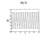
相関マトリックスを下記の式と仮定すると、
図10に示した相関関数の特徴は、前述した問題を回避するための本発明の概念を例示している。例えば、2個のアンテナの場合では、データを別個に差分変調される2個のストリームに分割することができる。ここで、一方のストリームは偶数のサブキャリアを通って送信され、他方のサブキャリアは奇数のサブキャリアを介して送信されるため、対応するストリームの値は常に相関関係のあるキャリアを介して、例えば周波数領域の中の相関関係のあるチャネル係数に関連したキャリア周波数を介して送信される。 The features of the correlation function shown in FIG. 10 illustrate the concept of the present invention to avoid the aforementioned problems. For example, in the case of two antennas, the data can be divided into two streams that are differentially modulated separately. Here, since one stream is transmitted through even subcarriers and the other subcarrier is transmitted through odd subcarriers, the value of the corresponding stream is always via correlated carriers, For example, transmitted over a carrier frequency associated with a correlated channel coefficient in the frequency domain.
この概念は、図9のチャネル係数を示す図11に例示されている。第1の値に近付く絶対値を有するチャネル係数は、差分コード化されたストリーム1を送信する場合に適用されるキャリア周波数を決定することが、付加的に示されている。従って、第2の値に近付く絶対値を有するチャネル係数は、差分コード化されたストリームを送信する場合に適用されるキャリア周波数を決定する。前述したように、チャネルを評価するために、別の参照記号が第2のストリーム(ストリーム2)のために必要とされる。
This concept is illustrated in FIG. 11, which shows the channel coefficients of FIG. It is additionally shown that a channel coefficient having an absolute value approaching the first value determines the carrier frequency applied when transmitting the differentially encoded
以下に説明されるように、周波数選択チャネルに対して同様の結果を得ることができる。 Similar results can be obtained for frequency selective channels, as described below.
図12は、周波数選択チャネルの場合に、2個の送信アンテナ及び△2=NS/2による周期的遅延を有する周期的遅延ダイバーシチに対して2個のストリームを用いる差分コード化方式を例示する。図11で検討された平坦なフェージングチャネルとは対照的に、チャネル係数の絶対値は周波数の増加と共に変化する。しかしながら、前述した周期的遅延ダイバーシチに関しては、全ての第2のチャネル係数が相関される。このため、全ての第2のキャリアは差分コード化されたストリーム1の送信に適用され、また全ての第2のキャリアは差分コード化されたストリーム2の送信に適用される。
FIG. 12 illustrates a differential coding scheme using two streams for periodic delay diversity with two transmit antennas and a periodic delay with Δ 2 = N S / 2 for a frequency selective channel. . In contrast to the flat fading channel discussed in FIG. 11, the absolute value of the channel coefficient changes with increasing frequency. However, for the cyclic delay diversity described above, all second channel coefficients are correlated. For this reason, all the second carriers are applied to the transmission of the differentially coded
図12に表された周波数応答の絶対値は、各送信アンテナから各受信アンテナまでの平均電力が等しい、D+1=3の独立したフェージングタップh(nm) t(d)を有するチャネルによって決定される。本来のチャネル(すなわち、ダイバーシチ効果のないチャネル)の周波数選択性のために、1つおきのサブキャリアのチャネルタップH(m) k(d)はもはや同一ではない。しかしながら、本来のチャネルが3つの隣接するサブキャリアにわたってほぼ一定である場合、平坦なフェージングチャネルの場合と同じ差分変調の方式を適用できる。 The absolute value of the frequency response represented in FIG. 12 is determined by a channel with D + 1 = 3 independent fading taps h (nm) t (d) with equal average power from each transmit antenna to each receive antenna. . Because of the frequency selectivity of the original channel (ie, the channel without diversity effect), the channel taps H (m) k (d) of every other subcarrier are no longer identical. However, if the original channel is approximately constant over three adjacent subcarriers, the same differential modulation scheme can be applied as for a flat fading channel.
例えば、△2=NS/4の周期的遅延が選択される場合、用語
![]()
![]()
図13は、図12の周波数選択チャネルに対して2個の送信アンテナと周期的遅延△2=NS/2とを有する周期的遅延ダイバーシチに対する相関関数R1dを示す。この相関関数が、相関されたチャネル係数を特徴付ける値を有することが分かる。これらの値は、相関が取れないチャネル係数を特徴付ける相関関数の値よりも大きい。 FIG. 13 shows the correlation function R 1d for periodic delay diversity with two transmit antennas and a periodic delay Δ 2 = N S / 2 for the frequency selective channel of FIG. It can be seen that this correlation function has a value characterizing the correlated channel coefficients. These values are greater than the value of the correlation function that characterizes the channel coefficients that cannot be correlated.
この時点までに、マルチキャリア信号を提供する本発明の装置は、送信機の中に取り入れられた周期的遅延ダイバーシチの状況の中で検討された。しかしながら、本発明の方式は適用されるダイバーシチ方式に関連する効果を考慮に入れるように、送信される信号を前処理することに基づいているため、本発明の概念は他のダイバーシチ方式が使用される場合にも適用することができる。例えば、位相シフトを周波数/時間変換の前にマルチキャリア信号に取り入れることによって、ダイバーシチを導入することもできる。このため、NT個のアンテナシステムについては、NT個の周波数領域/時間領域の変換を実行する必要がある。 Up to this point, the device of the present invention providing a multi-carrier signal has been considered in the context of periodic delay diversity incorporated in the transmitter. However, since the inventive scheme is based on preprocessing the transmitted signal to take into account the effects associated with the applied diversity scheme, the inventive concept uses other diversity schemes. This can also be applied. For example, diversity can be introduced by incorporating a phase shift into the multi-carrier signal before frequency / time conversion. For this reason, NT frequency domain / time domain transformations need to be performed for NT antenna systems.
本発明の概念を、位相ダイバーシチの場合にもさらに適用することができる。位相ダイバーシチを取り入れるために、本発明による装置は、その後の位相シフトに必要なマルチキャリア信号のコピーを生成するための手段をさらに備える。このため、位相シフトされた信号をマルチキャリア信号から位相シフトによって引き出すことができる。次に、周波数領域/時間領域の変換器は、マルチキャリア信号から取り出すことができる信号を、前述したような単純な方法で変換された信号に変換する。 The concept of the present invention can be further applied to the case of phase diversity. In order to incorporate phase diversity, the apparatus according to the invention further comprises means for generating a copy of the multicarrier signal necessary for the subsequent phase shift. For this reason, the phase-shifted signal can be extracted from the multicarrier signal by phase shifting. Next, the frequency / time domain converter converts the signal that can be extracted from the multi-carrier signal into a signal converted by a simple method as described above.
前述したように、マルチキャリア信号から取り出すことができる信号を提供するために、本発明の装置は、マルチキャリア信号から取り出すことができる信号を提供するために、マルチキャリア信号のコピーを提供するための手段及びマルチキャリア信号のコピーを位相シフトするための手段を含む信号を提供するための手段を備える。 As described above, in order to provide a signal that can be extracted from a multi-carrier signal, the apparatus of the present invention provides a copy of the multi-carrier signal to provide a signal that can be extracted from the multi-carrier signal. And means for providing a signal including means for phase shifting a copy of the multicarrier signal.
受信機においては、好ましいことに複数の受信アンテナが信号を受信するために使用される。一般に、保護間隔を除いた後のOFDM送信の場合では、対応する受信されたマルチキャリア信号を提供するために、時間領域/周波数領域の変換が各受信アンテナに対応する各信号に対して適用される。 In the receiver, preferably a plurality of receive antennas are used to receive the signal. In general, in the case of OFDM transmission after removing the guard interval, a time domain / frequency domain transform is applied to each signal corresponding to each receive antenna to provide a corresponding received multi-carrier signal. The
図14は、1つ又は複数の受信アンテナによって受信されて結果として生じた信号のマルチキャリア信号から出力信号を提供するための本発明による装置のブロック図を示す。マルチキャリア形送信方式、例えばODFM方式の場合では、受信されたマルチキャリア信号には、マルチキャリア方式のキャリア周波数に対するスペクトル係数が含まれる。このスペクトル係数は、一連の離散値で構成される複数の下位信号を得るために入力信号を処理することから形成される。ここで、複数の下位信号は全体としてみると入力信号と同じ情報を有し、下位信号の数は2に等しいか又は2よりも大きい。入力信号は、複数の下位信号の離散値を次に来るキャリア周波数に割り当てて、マルチキャリア信号を得ることによってさらに形成される。ここで、第1の下位信号の一連の離散値は第1のキャリア周波数から始めてS番目毎のキャリア周波数に割り当てられ、第2の下位信号の一連の離散値は第2のキャリア周波数から始めてS番目毎のキャリア周波数に割り当てられ、第2のキャリア周波数は第1のキャリア周波数とは異なり、Sは下位信号の数に等しいか又はそれよりも大きい数を示す。 FIG. 14 shows a block diagram of an apparatus according to the invention for providing an output signal from a multi-carrier signal of the resulting signal received by one or more receiving antennas. In the case of a multi-carrier transmission scheme, for example, the ODFM scheme, the received multi-carrier signal includes a spectrum coefficient for the carrier frequency of the multi-carrier scheme. This spectral coefficient is formed from processing the input signal to obtain a plurality of sub-signals composed of a series of discrete values. Here, the plurality of subordinate signals have the same information as the input signal as a whole, and the number of subordinate signals is equal to or greater than two. The input signal is further formed by assigning discrete values of the plurality of subordinate signals to the next carrier frequency to obtain a multicarrier signal. Here, a series of discrete values of the first subordinate signal is assigned to every S-th carrier frequency starting from the first carrier frequency, and a series of discrete values of the second subordinate signal starting from the second carrier frequency is S. The second carrier frequency is different from the first carrier frequency, and S indicates a number equal to or greater than the number of lower signals.
受信されたマルチキャリア信号は、例えば前述した本発明の装置を含む送信機によって発生することができる。 The received multicarrier signal can be generated, for example, by a transmitter including the apparatus of the present invention described above.
出力信号を提供する装置は、複数の入力部及び複数の出力部を有する再割当て部(re-assigner)1401を備えている。再割当て部1401の出力部は、出力信号を提供するための出力部を有する再処理装置(re-processor)1403に接続される。
The apparatus for providing an output signal includes a re-assigner 1401 having a plurality of inputs and a plurality of outputs. The output unit of the
下記の中で、図14に示した装置の機能性が説明される。 In the following, the functionality of the device shown in FIG. 14 will be described.
再割当て部1401は、前述した割当て部の動作とは逆の動作を実行するように構成される。特に、スペクトル係数は、ナンバリング指数の集合の中のナンバリング指数に関連付けられる。再割当て部は、複数の下位信号から第1の下位信号の受信された信号を提供するために、第1のナンバリング指数を有するスペクトル係数から始めてS番目毎のスペクトル係数を選択するように動作する。別の方法では、割当て部は、複数の下位信号から第2の下位信号の受信された信号を提供するために、第2のナンバリング指数を有するスペクトル係数から始めてS番目毎のスペクトル係数を選択するように動作する。ここで、第1のナンバリング指数は、第2のナンバリング指数とは異なっている。Sは、下位信号の数を表す。
The
再割当て部1401は、スペクトル係数を複数の下位信号の中のそれぞれの下位信号の受信された信号にマッピングするマッパー(mapper)とすることができる。例えば、再割当て部1401は、インターリーバ又はマトリックス構造を有するブロック形インターリーバとすることができる。例えば、再割当て部1401は、本発明の割当て部に関連して前述したように、S個の列と、マルチキャリア方式のキャリア周波数の数をSによって割って決定される数の行とを有する、又は逆の場合も同様のブロック形インターリーバである。
The
複数の下位信号の受信された信号は、再割当て部1401の出力部を経由して再処理装置1403に送られる。この再処理装置1403は、送信機の中で実行される本発明によるプロセッサに関連して説明された動作とは逆の動作を行うことができる。送信機において、入力信号を2に等しい又は2よりも大きな数の下位信号に分割することによって、また複数の下位信号を得るために、それぞれの分割された信号をデコーディングすることによって複数の下位信号が形成される場合、再処理装置1403は、複数のデコードされ受信された下位信号を提供するために、受信された下位信号を別個にデコードするための手段を備える。この場合、受信された下位信号は、再割当て部1401によって複数の下位信号の受信された信号として提供される。さらに、再処理装置1403は、入力信号の受信された信号を得るために、出力信号として複数のデコードされた下位信号を結合するための手段を備えることができる。結合するための手段は、複数のデコードされた下位信号を出力信号のストリームにデマルチプレクスするデマルチプレクサとすることが好ましい。
The received signals of the plurality of subordinate signals are sent to the
送信機において、分割された信号が下位信号の値を得るために、2個の分割された信号値を結合することによってコード化される場合、本発明の再処理装置1403が備えるデコーディングするための手段は、受信された下位信号に対して、デコード及び受信された下位信号の値を提供するために、2個の受信された下位信号の値を結合するように動作する。特に、分割された信号が差分コード化される場合、デコーディングするための手段は受信された下位信号に対して、コード化(コーディング)に関連した動作とは逆の動作を行う差分デコーダをさらに備える。さらに、送信機においてインターリービングが使用される場合、再処理するための手段は、デコード及び受信された下位信号に対してインターリーブされデコード及び受信された下位信号をデコード及び受信された下位信号として提供するためのインターリーバを備える。複数のデコードされ受信された下位信号は、前に説明したように、結合するための手段が備えるマルチプレクサによる出力信号として、多重化され受信された信号にさらに多重化される。
In the transmitter, when the divided signal is coded by combining two divided signal values in order to obtain the value of the lower signal, in order to decode the
一般に、本発明の装置は、マルチキャリア信号と同じ情報の内容を有する別のマルチキャリア信号を受信するように構成することができる。この場合、本発明による再割当て部はさらに、別の受信されたマルチキャリア信号を再割り当てして、複数の下位信号の別の受信された信号を得るように動作することができる。この場合は、再処理装置は出力信号を提供する場合、複数の下位信号の別の受信された信号をさらに使用するように適合される。 In general, the apparatus of the present invention can be configured to receive another multicarrier signal having the same information content as the multicarrier signal. In this case, the reallocation unit according to the present invention can further operate to reallocate another received multicarrier signal to obtain another received signal of the plurality of sub-signals. In this case, the reprocessing device is adapted to further use another received signal of the plurality of sub-signals when providing the output signal.
再処理装置は、前述したように、出力信号の一連の値に対してソフトな値(soft value)を出力するようにさらに構成することができる。 The reprocessing device can be further configured to output a soft value for a series of values of the output signal, as described above.
図15は、マルチストリーム(multi-stream)の差分変調を行う周期的遅延ダイバーシチに対する本発明による受信機の構造のブロック図である。 FIG. 15 is a block diagram of the structure of a receiver according to the present invention for periodic delay diversity with multi-stream differential modulation.
図15の装置は、それぞれの受信された信号経路を決定する複数の受信アンテナ1501を備えている。それぞれのアンテナ1501を経由して受信された信号は、OFDM変調方式に関連した保護間隔を取り除くためのそれぞれの手段1503に送られる。保護間隔を取り除くための手段1503の各々は、時間/周波数変換器1505に接続された出力部を有する。変換器1505は、単に実施例として示すと、高速フーリエ変換(FFT)、離散高速フーリエ変換、離散フーリエ変換、又は任意の他の時間領域/周波数領域の変換を実行するように動作する。
The apparatus of FIG. 15 includes a plurality of receiving
変換器1505のそれぞれは、検討される信号経路に関連したそれぞれの再割当て部1507に接続された複数の出力部を有する。本発明のそれぞれの再割当て部1507は、下位信号の数Sによって決定される複数の出力部を有する。全体で、nR個の再割当て部1507が使用される。ここで、nRは受信アンテナ1501の数を指す。再割当て部1507の後段には、S個のデコーダ1509が配列される。それぞれのプロセッサ1509は、下位信号のnR個の受信された信号を受信するためにnR個の入力部を有する。より具体的に述べると、デコーダ1509のそれぞれの複数の入力部のそれぞれは、同じ下位信号のnR個の受信された信号を収集するために別個の再割当て部1507に接続される。それぞれのデコーダ1509は、インターリーバ1511に接続された出力部を有する。ここで、それぞれのインターリーバ1511は、マルチプレクサ1513に接続された出力部を有する。このマルチプレクサ1513(MUX)は、インターリーバ1515に接続された出力部を有し、インターリーバ1515は前進型エラー信号訂正用デコーダ1517(FECデコーダ)に接続された出力部を有する。
Each of the
下記に、図15に示した装置の機能性が説明される。 In the following, the functionality of the device shown in FIG. 15 will be described.
前述したように、本発明の受信機はnR個のアンテナ1501を備えている。再割当て部1507は、各ストリームのnR個の受信された信号をそれぞれのデコーダ1509に割り当てる。(オプションの)インターリーバ1511及び1515によって実行されるインターリービングの後で、前進型エラー信号訂正用デコーダ1517は周波数ダイバーシチを取り出し、情報ビットに対してソフト又はハードな決定(soft or hard decision)を与える。
As described above, the receiver of the present invention includes n R antennas 1501. The
デコーダ1509は、差分コード化/変調された情報を取り出すために、差分デコーダ又は差分復調器とすることができる。
図15の構造は、信号を受信する場合に適切である。この送信機の構造では、例えば周期的遅延ダイバーシチ方式が適用された。しかしながら、ダイバーシチ動作の直線性のためにダイバーシチが受信機の中に取り入れられる場合、本発明の受信についての概念も適用できる。このシナリオは、図16で検討される。 The structure of FIG. 15 is appropriate when receiving a signal. In the structure of this transmitter, for example, a periodic delay diversity method is applied. However, if diversity is incorporated into the receiver due to the linearity of the diversity operation, the concept of reception of the present invention is also applicable. This scenario is discussed in FIG.
図16に示した受信機の構造は、単に実施例として示すと、第1の受信アンテナ1601及び第2の受信アンテナ1603を備えている。第1の受信アンテナ1601は第1の信号経路を定義し、第2の受信アンテナ1603は第2の信号経路を定義する。第2の信号経路は、出力部を有している、遅延を取り入れるための手段1605に接続されている。手段1605の出力部及び第1の受信アンテナ1601に関連した第1の信号経路の両方は、加算器1607に接続される。この加算器1607は、複数の出力部を有する時間/周波数変換器1609に接続された出力部を有する。時間/周波数変換器1609の複数の出力部は、本発明による受信機装置1611に接続される。受信機装置1611は、出力信号を提供するための出力部を有している。
The receiver structure shown in FIG. 16 includes a
加算器1607は、出力部を介して受信された信号を与える。この受信された信号は、第1の受信アンテナ1601が受信した信号に対応する第1の信号と、第2の受信アンテナ1603が受信した信号に対応する第2の信号の周期的にシフトされた信号とを重ね合わせた信号である。この(周期的な)シフトすなわち遅延は、送信機の中に組み込まれた周期的遅延ダイバーシチに関連して前に説明したものと同じ方法で動作する手段1605によって取り入れられる。
この時点までに、無相関のチャネル係数が受信機において知られていると仮定されていた。しかしながら、受信機が周波数領域のチャネル応答係数の相関特性に関する何らかの情報を持っていない場合、同じ共分散(すなわち、相関)関数を実行する必要がある。そうするために、本発明の受信機装置は、受信されたマルチキャリア信号の相関関数を実行するための相関器をさらに備えることができる。この相関器は、受信されたマルチキャリア信号の相関関数を決定するように動作する。無相関のチャネル係数はキャリア周波数間の相関特性に直接影響するため、こうした相関器はマルチキャリア信号の相関特性これによりチャネル係数の相関特性を直接決定する。 By this time, it was assumed that uncorrelated channel coefficients were known at the receiver. However, if the receiver does not have any information about the correlation characteristics of the frequency domain channel response coefficients, it must perform the same covariance (ie, correlation) function. To do so, the receiver apparatus of the present invention can further comprise a correlator for performing a correlation function of the received multicarrier signal. The correlator operates to determine the correlation function of the received multicarrier signal. Since an uncorrelated channel coefficient directly affects the correlation characteristic between carrier frequencies, such a correlator directly determines the correlation characteristic of the multi-carrier signal and thereby the channel coefficient.
実行方法にもよるが、マルチキャリア信号を提供する方法すなわち受信されたマルチキャリア信号から出力信号を提供するための本発明による方法に対する要求事項は、ハードウェア又はソフトウェアの中で実現することができる。この実現は、本発明の方法が実行されるようにプログラム可能なコンピュータシステムと共に動作できるディジタル記憶媒体、特に中に記憶された電気的に読取り可能な制御信号を有するディスク又はCDを用いて行うことができる。従って、本発明は一般的に、コンピュータが読取り可能な担体上にプログラムコードが記憶されたコンピュータプログラム製品である。このプログラムコードは、コンピュータプログラム製品がコンピュータ上で実行される場合に本発明による方法を実行する。言い換えると、本発明の方法はこのように、コンピュータ上で実行される場合に本発明の方法を実行するためのプログラムコードを有するコンピュータプログラムである。 Depending on the method of execution, the requirements for a method for providing a multicarrier signal, ie a method according to the invention for providing an output signal from a received multicarrier signal, can be realized in hardware or software. . This implementation is performed using a digital storage medium that can operate with a computer system that can be programmed to carry out the method of the invention, in particular a disk or CD having electrically readable control signals stored therein. Can do. Thus, the present invention is generally a computer program product in which program code is stored on a computer readable carrier. This program code performs the method according to the invention when the computer program product is executed on a computer. In other words, the method of the present invention is thus a computer program having program code for performing the method of the present invention when executed on a computer.
Claims (21)
入力信号を処理し一連の離散値から成る複数の下位信号を得るプロセッサ(101)であって、前記下位信号は全体として前記入力信号と同じ情報を持つものであり、前記下位信号の数は2以上であり、前記入力信号を前記下位信号の数に等しい数の分割信号に分割するデバイダ(201)と、差分をとって独立して個別に分割信号を符号化し前記下位信号の下位信号を得る差分コーダ(203、409)とを具備するプロセッサ(101)と、
前記下位信号の前記離散値を一連の搬送周波数に割当て、マルチキャリア信号を得る割当て部(103、411)と
を具備し、
前記割当て部(103、411)は、第1の下位信号の一連の離散値を第1の搬送周波数から始めてS番目毎の搬送周波数に割当て、第2の下位信号の一連の離散値を第2の搬送周波数から始めてS番目毎の搬送周波数に割当てるものであり、ここで前記第1の搬送周波数は前記第2の搬送周波数とは異なるものである、
装置。An apparatus for providing a multicarrier signal transmitted from a transmission point to a reception point via a plurality of carrier frequencies,
A processor (101) for processing an input signal to obtain a plurality of subordinate signals composed of a series of discrete values, wherein the subordinate signal has the same information as the input signal as a whole, and the number of subordinate signals is 2 A divider (201) that divides the input signal into a number of divided signals equal to the number of the lower signals, and obtains a lower signal of the lower signal by independently encoding the divided signals by taking the difference. A processor (101) comprising a differential coder (203, 409);
An assigning unit (103, 411) for assigning the discrete values of the lower signal to a series of carrier frequencies and obtaining a multi-carrier signal;
The assigning unit (103, 411) assigns a series of discrete values of the first subordinate signal to the S-th carrier frequency starting from the first carrier frequency, and assigns a series of discrete values of the second subordinate signal to the second The first carrier frequency is different from the second carrier frequency, starting with the first carrier frequency.
apparatus.
前記入力信号を複数のデマルチプレクス処理信号にデマルチプレクス処理するデマルチプレクサ(405)と、
前記デマルチプレクス処理信号の中のあるデマルチプレクス処理信号に対し、前記デマルチプレクス処理信号をインタリーブ処理したものを分割信号として提供するインタリーバ(407)と
を具備するものである、請求項1に記載の装置。The divider (201)
A demultiplexer (405) for demultiplexing the input signal into a plurality of demultiplexed signals;
An interleaver (407) for providing a demultiplexed signal obtained by interleaving the demultiplexed signal as a divided signal with respect to a certain demultiplexed signal in the demultiplexed signal. The device described in 1.
前記第1の搬送周波数は第1のナンバリング指数に関連するものであって、前記第1のナンバリング指数は、前記一連のナンバリング指数の集合の中で最小のナンバリング指数に等しくまたは大きいものであり、
前記第2の搬送周波数は、前記一連のナンバリング指数の集合の中の第2のナンバリング指数に関連するものであり、
前記第2のナンバリング指数は、前記第1のナンバリング指数とは異なるものであり、
前記割当て部(103、411)は、前記離散値をそれぞれナンバリング指数に割当てることにより、前記第1の下位信号の前記離散値をS番目毎の搬送周波数に割当て、前記下位信号の前記離散値をS番目毎の搬送周波数に割当てるものである、
請求項1〜3のいずれか一項に記載の装置。The series of carrier frequencies is associated with a numbering index in a set of numbering indices;
The first carrier frequency is associated with a first numbering index, and the first numbering index is equal to or greater than a minimum numbering index in the set of numbering indices;
The second carrier frequency is associated with a second numbering index in the set of numbering indices;
The second numbering index is different from the first numbering index;
The assigning unit (103, 411) assigns the discrete value of the first lower order signal to every S-th carrier frequency by assigning the discrete value to a numbering index, and assigns the discrete value of the lower order signal to the S-th carrier frequency. Assigned to every S-th carrier frequency,
The apparatus according to any one of claims 1 to 3.
前記変換信号の前記コピーに遅延を発生させる手段(422)と
をさらに具備するものであって、
前記変換信号の前記コピーは、複数の離散値の中で最小のナンバリング指数を有するある離散値から始まる前記離散値を有するものであり、
前記変換信号の前記コピーに遅延を発生させる前記手段(422)は、前記ある離散値が前記最小のナンバリング指数よりも大きいナンバリング指数となるように、前記離散値を再度番号付けすることにより前記変換信号の前記コピーをシフトするものである、
請求項6に記載の装置。Means (415) for providing a copy of the converted signal;
Means (422) for generating a delay in the copy of the converted signal,
The copy of the transformed signal has the discrete value starting from a discrete value having a minimum numbering index among a plurality of discrete values;
The means for generating a delay in the copy of the transformed signal (422) renumbers the discrete values such that the certain discrete value is a numbering index greater than the minimum numbering index. Shifting the copy of the signal,
The apparatus according to claim 6.
前記マルチキャリア信号の前記コピーを位相シフトし、前記マルチキャリア信号から誘導できる信号を提供する手段と
を具備する手段であって、前記マルチキャリア信号から誘導できる信号を提供する手段をさらに具備する請求項6または7に記載の装置。Means for providing a copy of the multi-carrier signal;
Means for phase-shifting the copy of the multi-carrier signal and providing a signal derivable from the multi-carrier signal, further comprising means for providing a signal derivable from the multi-carrier signal. Item 8. The device according to Item 6 or 7.
前記スペクトル係数は、入力信号を処理し一連の離散値から成る複数の下位信号を得ることにより前記入力信号から形成されるものであって、前記下位信号の前記離散値を一連の搬送周波数に割当てマルチキャリア信号を得ることにより形成されるものであり、ここで前記下位信号は全体として前記入力信号と同じ情報を持つものであり、前記下位信号の数は2以上であり、
第1の下位信号の一連の離散値は、第1の搬送周波数から始めてS番目毎の搬送周波数に割り当てられるものであり、
第2の下位信号の一連の離散値は、第2の搬送周波数から始めてS番目毎の搬送周波数に割り当てられるものであり、
前記第2の搬送周波数は前記第1の搬送周波数とは異なるものであり、
Sは前記下位信号の数以上の数を表すものである、
受信したマルチキャリア信号から出力信号を提供する受信機装置であって、
前記スペクトル係数を再度割当てるものであって、受信した前記下位信号を提供する再割当て部(1401、1507)と、
受信した前記下位信号を再処理し、受信した前記入力信号を前記出力信号として得るリプロセッサ(1403)であって、
受信した前記下位信号をそれぞれ復号化し、複数の復号化された受信下位信号を提供する手段であって、差分デコーダ(1509)を具備する手段と、
前記復号化された受信下位信号を結合し、受信した前記入力信号を前記出力信号として得る手段と
を具備するリプロセッサ(1403)と
を具備する装置。The received multicarrier signal includes the spectrum coefficient of the carrier frequency of the multicarrier system,
The spectral coefficient is formed from the input signal by processing the input signal to obtain a plurality of sub-signals consisting of a series of discrete values, and assigning the discrete values of the sub-signals to a series of carrier frequencies Formed by obtaining a multi-carrier signal, wherein the lower signal has the same information as the input signal as a whole, and the number of the lower signals is two or more,
A series of discrete values of the first sub-signal is assigned to every S-th carrier frequency starting from the first carrier frequency,
A series of discrete values of the second subordinate signal is assigned to every S-th carrier frequency starting from the second carrier frequency,
The second carrier frequency is different from the first carrier frequency;
S represents a number greater than or equal to the number of the lower signals.
A receiver device for providing an output signal from a received multicarrier signal,
A re-allocation unit (1401, 1507) for re-allocating the spectral coefficient and providing the received lower signal;
A reprocessor (1403) that reprocesses the received lower signal and obtains the received input signal as the output signal;
Means for decoding each of the received subordinate signals and providing a plurality of decoded received subordinate signals, comprising: a differential decoder (1509);
A reprocessor (1403) comprising: means for combining the decoded received subordinate signals and obtaining the received input signal as the output signal.
前記再割当て部(1401、1507)は、第1のナンバリング指数を有するスペクトル係数から始めてS番目毎のスペクトル係数を選択し、受信した前記下位信号の第1の下位信号を提供するものであって、第2のナンバリング指数を有するスペクトル係数から始めてS番目毎のスペクトル係数を選択し、受信した前記下位信号の第2の下位信号を提供するものであり、
前記第1のナンバリング指数は前記第2のナンバリング指数とは異なるものである、
請求項9に記載の装置。The spectral coefficient is related to a numbering index in a set of numbering indices;
The reassignment unit (1401, 1507) selects every S-th spectral coefficient starting from a spectral coefficient having a first numbering index, and provides a first lower signal of the received lower signal. , Selecting every Sth spectral coefficient starting from a spectral coefficient having a second numbering index and providing a second lower signal of the received lower signal;
The first numbering index is different from the second numbering index;
The apparatus according to claim 9.
前記変換器(1505)は時間・周波数変換を行うものである、
請求項9〜14のいずれか一項に記載の装置。The received multicarrier signal is formed from the received signal by a converter that converts the received signal into the received multicarrier signal;
The converter (1505) performs time / frequency conversion.
The device according to any one of claims 9 to 14.
前記再割当て部(1401、1507)はさらに、受信した前記別のマルチキャリア信号を再度割当て、受信した別の前記下位信号を得るものであり、
前記リプロセッサ(1403)は、前記出力信号を提供する際に受信した前記別の複数の下位信号をさらに用いるものである、
請求項9に記載の装置。An apparatus for receiving another multicarrier signal having the same amount of information as the multicarrier signal,
The reassignment unit (1401, 1507) further reassigns the received other multicarrier signal to obtain another received lower signal,
The reprocessor (1403) further uses the plurality of other subordinate signals received when providing the output signal.
The apparatus according to claim 9.
入力信号を処理し一連の離散値から成る複数の下位信号を得るステップであって、前記下位信号は全体として前記入力信号と同じ情報を持つものであり、前記下位信号の数は2以上であり、前記入力信号を前記下位信号の数に等しい数の分割信号に分割するステップと、それぞれ独立して分割信号を符号化し前記下位信号の下位信号を得るステップとを含むステップと、
前記下位信号の前記離散値を一連の搬送周波数に割当て、マルチキャリア信号を得るステップと
を含むものであり、
ここで第1の下位信号の一連の離散値は第1の搬送周波数から始めてS番目毎の搬送周波数に割当てられ、第2の下位信号の一連の離散値は第2の搬送周波数から始めてS番目毎の搬送周波数に割当てられるものであり、
前記第2の搬送周波数は前記第1の搬送周波数とは異なるものであり、
Sは前記下位信号の数以上の数を表すものである、
方法。A method for providing a multicarrier signal transmitted from a transmission point to a reception point via a plurality of carrier frequencies,
Processing the input signal to obtain a plurality of subordinate signals comprising a series of discrete values, wherein the subordinate signal has the same information as the input signal as a whole, and the number of subordinate signals is two or more Dividing the input signal into a number of divided signals equal to the number of the lower signals, and independently encoding the divided signals to obtain the lower signals of the lower signals,
Assigning the discrete values of the sub-signals to a series of carrier frequencies to obtain a multi-carrier signal,
Here, a series of discrete values of the first subordinate signal are assigned to every S th carrier frequency starting from the first carrier frequency, and a series of discrete values of the second subordinate signal are assigned to the S th carrier frequency starting from the second carrier frequency. Assigned to each carrier frequency,
The second carrier frequency is different from the first carrier frequency;
S represents a number greater than or equal to the number of the lower signals.
Method.
前記スペクトル係数は、入力信号を処理し一連の離散値から成る複数の下位信号を得ることにより前記入力信号から形成されるものであって、前記下位信号の前記離散値を一連の搬送周波数に割当てマルチキャリア信号を得ることにより形成されるものであり、ここで前記下位信号は全体として前記入力信号と同じ情報を持つものであり、前記下位信号の数は2以上であり、
第1の下位信号の一連の離散値は、第1の搬送周波数から始めてS番目毎の搬送周波数に割り当てられるものであり、
第2の下位信号の一連の離散値は、第2の搬送周波数から始めてS番目毎の搬送周波数に割り当てられるものであり、
前記第2の搬送周波数は前記第1の搬送周波数とは異なるものである、
受信したマルチキャリア信号から出力信号を提供する方法であって、
前記スペクトル係数を再度割当てるものであって、受信した前記下位信号を提供するステップと、
受信した前記下位信号を再処理し、受信した前記入力信号を前記出力信号として得るステップであって、該再処理が、複数の復号化された受信下位信号を提供するために、受信した前記下位信号をそれぞれ復号化し、受信した前記入力信号を前記出力信号として得るために、前記復号化された受信下位信号を結合することを含むステップと
を含む方法。The received multicarrier signal includes the spectrum coefficient of the carrier frequency of the multicarrier system,
The spectral coefficient is formed from the input signal by processing the input signal to obtain a plurality of sub-signals consisting of a series of discrete values, and assigning the discrete values of the sub-signals to a series of carrier frequencies Formed by obtaining a multi-carrier signal, wherein the lower signal has the same information as the input signal as a whole, and the number of the lower signals is two or more,
A series of discrete values of the first sub-signal is assigned to every S-th carrier frequency starting from the first carrier frequency,
A series of discrete values of the second subordinate signal is assigned to every S-th carrier frequency starting from the second carrier frequency,
The second carrier frequency is different from the first carrier frequency;
A method of providing an output signal from a received multicarrier signal,
Reassigning the spectral coefficients, providing the received sub-signals;
Re-processing the received sub-signal and obtaining the received input signal as the output signal, the re-processing receiving the sub-signal to provide a plurality of decoded received sub-signals Combining the decoded received sub-signals to each decode a signal and obtain the received input signal as the output signal.
Applications Claiming Priority (2)
| Application Number | Priority Date | Filing Date | Title |
|---|---|---|---|
| EP03016002 | 2003-07-14 | ||
| PCT/EP2003/009817 WO2005006696A1 (en) | 2003-07-14 | 2003-09-04 | Apparatus and method for providing a multi-carrier signal to be transmitted and apparatus and method for providing an output signal from a received multi-carrier signal |
Publications (3)
| Publication Number | Publication Date |
|---|---|
| JP2007515812A JP2007515812A (en) | 2007-06-14 |
| JP2007515812A5 JP2007515812A5 (en) | 2009-07-02 |
| JP4339850B2 true JP4339850B2 (en) | 2009-10-07 |
Family
ID=34042839
Family Applications (1)
| Application Number | Title | Priority Date | Filing Date |
|---|---|---|---|
| JP2005503814A Expired - Lifetime JP4339850B2 (en) | 2003-07-14 | 2003-09-04 | Apparatus and method for providing a transmitted multi-carrier signal, and apparatus and method for providing an output signal from a received multi-carrier signal |
Country Status (5)
| Country | Link |
|---|---|
| EP (1) | EP1661346B1 (en) |
| JP (1) | JP4339850B2 (en) |
| AU (1) | AU2003258702A1 (en) |
| DE (1) | DE60322602D1 (en) |
| WO (1) | WO2005006696A1 (en) |
Families Citing this family (11)
| Publication number | Priority date | Publication date | Assignee | Title |
|---|---|---|---|---|
| KR101075761B1 (en) | 2005-02-02 | 2011-10-24 | 삼성전자주식회사 | Transmitter for transmitting symbols in the mimo system and therefor method |
| US20060203793A1 (en) * | 2005-03-09 | 2006-09-14 | Lucent Technologies, Inc. | Method for increasing capacity in a wireless communications system |
| EP2940953B1 (en) * | 2010-02-04 | 2017-07-26 | LG Electronics Inc. | Broadcast signal receiver using mimo processing with a mimo rotation matrix |
| WO2011096735A2 (en) * | 2010-02-04 | 2011-08-11 | 엘지전자 주식회사 | Broadcast signal transmitter and receiver, and broadcast signal transmitting and receiving method |
| WO2011096739A2 (en) * | 2010-02-04 | 2011-08-11 | 엘지전자 주식회사 | Broadcast signal transmitter and receiver, and broadcast signal transmitting and receiving method |
| WO2011096734A2 (en) * | 2010-02-04 | 2011-08-11 | 엘지전자 주식회사 | Broadcast signal transmitter and receiver, and broadcast signal transmitting and receiving method |
| DK2541914T3 (en) * | 2010-02-23 | 2016-02-29 | Lg Electronics Inc | Transmission signal sender / receiver and procedure to send / receive transmission signal |
| DK2541907T3 (en) * | 2010-02-23 | 2016-07-25 | Lg Electronics Inc | Transmission signal sender / receiver and method for transmission signal transmission / reception |
| EP2541906B1 (en) * | 2010-02-23 | 2019-06-05 | LG Electronics Inc. | Broadcasting signal transmitter and broadcasting signal transmission method |
| WO2014112796A1 (en) * | 2013-01-17 | 2014-07-24 | Lg Electronics Inc. | Apparatus for transmitting broadcast signals, apparatus for receiving broadcast signals, method for transmitting broadcast signals and method for receiving broadcast signals |
| EP3912290A4 (en) | 2019-01-17 | 2022-01-26 | ZTE Corporation | Contention-based payload transmissions using differential coding |
Family Cites Families (3)
| Publication number | Priority date | Publication date | Assignee | Title |
|---|---|---|---|---|
| US6144711A (en) * | 1996-08-29 | 2000-11-07 | Cisco Systems, Inc. | Spatio-temporal processing for communication |
| JP3726986B2 (en) * | 1997-08-07 | 2005-12-14 | ソニー株式会社 | COMMUNICATION METHOD, TRANSMISSION DEVICE, RECEPTION DEVICE, AND CELLULAR RADIO COMMUNICATION SYSTEM |
| JP2001069115A (en) * | 1999-08-27 | 2001-03-16 | Matsushita Electric Ind Co Ltd | Ofdm communication device |
-
2003
- 2003-09-04 EP EP03817407A patent/EP1661346B1/en not_active Expired - Lifetime
- 2003-09-04 DE DE60322602T patent/DE60322602D1/en not_active Expired - Lifetime
- 2003-09-04 WO PCT/EP2003/009817 patent/WO2005006696A1/en active IP Right Grant
- 2003-09-04 JP JP2005503814A patent/JP4339850B2/en not_active Expired - Lifetime
- 2003-09-04 AU AU2003258702A patent/AU2003258702A1/en not_active Abandoned
Also Published As
| Publication number | Publication date |
|---|---|
| EP1661346B1 (en) | 2008-07-30 |
| DE60322602D1 (en) | 2008-09-11 |
| EP1661346A1 (en) | 2006-05-31 |
| JP2007515812A (en) | 2007-06-14 |
| WO2005006696A1 (en) | 2005-01-20 |
| AU2003258702A1 (en) | 2005-01-28 |
Similar Documents
| Publication | Publication Date | Title |
|---|---|---|
| US7593472B2 (en) | Methods and apparatus for circulation transmissions for OFDM-based MIMO systems | |
| KR100698770B1 (en) | Apparatus and method for subcarrier mapping of stc data in broadband wireless communication system | |
| JP5686818B2 (en) | Dynamic tone grouping and coding of multicarrier quadrature amplitude modulation in OFDM | |
| CN101341668B (en) | Data communication method and wireless communication system in wireless system | |
| KR101643439B1 (en) | Division of bit streams to produce spatial paths for multicarrier transmission | |
| JP2006191645A (en) | Apparatus and method for space-time frequency block coding in a wireless communication system | |
| KR20060031924A (en) | Apparatus and method for minimizing peak to average power ratio in orthogonal frequency division multiplexing communication system | |
| KR20050120244A (en) | Apparatus and method for encoding/decoding space frequency block code for orthogonal frequency division multiplexing system | |
| EP1573936B1 (en) | Apparatus and method for cyclic delay diversity | |
| KR100584439B1 (en) | Apparatus and method for interference cancellation of ofdm system using multiple antenna | |
| JP4339850B2 (en) | Apparatus and method for providing a transmitted multi-carrier signal, and apparatus and method for providing an output signal from a received multi-carrier signal | |
| TWI465083B (en) | Method for encoding space-time codes in a wireless communication system having multiple antennas | |
| US20110134904A1 (en) | Method and apparatus for transmitting and receiving a data symbol stream | |
| WO2007013413A1 (en) | Transmitter, receiver and method for controlling the same | |
| JP4373339B2 (en) | Space, time and frequency diversity in multi-carrier systems | |
| KR20070005571A (en) | Wireless communication system, wireless communication apparatus, and resource assignment method used therein | |
| JP2007195129A (en) | Mimo-ofdm transmitter/receiver reducing signal waveform peak | |
| JP4296177B2 (en) | Multi-carrier system with transmit diversity | |
| JP2008511220A (en) | Apparatus and method for obtaining delay diversity | |
| JP7304406B2 (en) | Sending and receiving signals | |
| JP5851280B2 (en) | Radio receiving apparatus, radio communication apparatus, and radio receiving method | |
| JP2000196559A (en) | Data transmission system and its transmitter-receiver | |
| WO2008123713A1 (en) | Method for signal transmitting and apparatus for the same, method for signal receiving and apparatus for the same | |
| JP2009159445A (en) | Communication apparatus, communication system and communication control method |
Legal Events
| Date | Code | Title | Description |
|---|---|---|---|
| A131 | Notification of reasons for refusal |
Free format text: JAPANESE INTERMEDIATE CODE: A131 Effective date: 20090317 |
|
| A524 | Written submission of copy of amendment under article 19 pct |
Free format text: JAPANESE INTERMEDIATE CODE: A524 Effective date: 20090518 |
|
| TRDD | Decision of grant or rejection written | ||
| A01 | Written decision to grant a patent or to grant a registration (utility model) |
Free format text: JAPANESE INTERMEDIATE CODE: A01 Effective date: 20090612 |
|
| A01 | Written decision to grant a patent or to grant a registration (utility model) |
Free format text: JAPANESE INTERMEDIATE CODE: A01 |
|
| A61 | First payment of annual fees (during grant procedure) |
Free format text: JAPANESE INTERMEDIATE CODE: A61 Effective date: 20090702 |
|
| R150 | Certificate of patent or registration of utility model |
Ref document number: 4339850 Country of ref document: JP Free format text: JAPANESE INTERMEDIATE CODE: R150 Free format text: JAPANESE INTERMEDIATE CODE: R150 |
|
| FPAY | Renewal fee payment (event date is renewal date of database) |
Free format text: PAYMENT UNTIL: 20120710 Year of fee payment: 3 |
|
| FPAY | Renewal fee payment (event date is renewal date of database) |
Free format text: PAYMENT UNTIL: 20120710 Year of fee payment: 3 |
|
| FPAY | Renewal fee payment (event date is renewal date of database) |
Free format text: PAYMENT UNTIL: 20130710 Year of fee payment: 4 |
|
| R250 | Receipt of annual fees |
Free format text: JAPANESE INTERMEDIATE CODE: R250 |
|
| R250 | Receipt of annual fees |
Free format text: JAPANESE INTERMEDIATE CODE: R250 |
|
| R250 | Receipt of annual fees |
Free format text: JAPANESE INTERMEDIATE CODE: R250 |
|
| R250 | Receipt of annual fees |
Free format text: JAPANESE INTERMEDIATE CODE: R250 |
|
| R250 | Receipt of annual fees |
Free format text: JAPANESE INTERMEDIATE CODE: R250 |
|
| R250 | Receipt of annual fees |
Free format text: JAPANESE INTERMEDIATE CODE: R250 |
|
| R250 | Receipt of annual fees |
Free format text: JAPANESE INTERMEDIATE CODE: R250 |
|
| R250 | Receipt of annual fees |
Free format text: JAPANESE INTERMEDIATE CODE: R250 |
|
| R250 | Receipt of annual fees |
Free format text: JAPANESE INTERMEDIATE CODE: R250 |
|
| R250 | Receipt of annual fees |
Free format text: JAPANESE INTERMEDIATE CODE: R250 |
|
| R250 | Receipt of annual fees |
Free format text: JAPANESE INTERMEDIATE CODE: R250 |
|
| R250 | Receipt of annual fees |
Free format text: JAPANESE INTERMEDIATE CODE: R250 |
|
| EXPY | Cancellation because of completion of term |