JP4339524B2 - DATA TRANSMISSION METHOD, DATA TRANSMISSION DEVICE, DATA RECEPTION METHOD, DATA RECEPTION DEVICE, DATA RECORDING METHOD, AND DATA RECORDING DEVICE - Google Patents
DATA TRANSMISSION METHOD, DATA TRANSMISSION DEVICE, DATA RECEPTION METHOD, DATA RECEPTION DEVICE, DATA RECORDING METHOD, AND DATA RECORDING DEVICE Download PDFInfo
- Publication number
- JP4339524B2 JP4339524B2 JP2000613169A JP2000613169A JP4339524B2 JP 4339524 B2 JP4339524 B2 JP 4339524B2 JP 2000613169 A JP2000613169 A JP 2000613169A JP 2000613169 A JP2000613169 A JP 2000613169A JP 4339524 B2 JP4339524 B2 JP 4339524B2
- Authority
- JP
- Japan
- Prior art keywords
- data
- picture unit
- section
- editing section
- editing
- Prior art date
- Legal status (The legal status is an assumption and is not a legal conclusion. Google has not performed a legal analysis and makes no representation as to the accuracy of the status listed.)
- Expired - Fee Related
Links
Images


Classifications
-
- H—ELECTRICITY
- H04—ELECTRIC COMMUNICATION TECHNIQUE
- H04N—PICTORIAL COMMUNICATION, e.g. TELEVISION
- H04N21/00—Selective content distribution, e.g. interactive television or video on demand [VOD]
- H04N21/40—Client devices specifically adapted for the reception of or interaction with content, e.g. set-top-box [STB]; Operations thereof
- H04N21/43—Processing of content or additional data, e.g. demultiplexing additional data from a digital video stream; Elementary client operations, e.g. monitoring of home network or synchronising decoder's clock; Client middleware
- H04N21/434—Disassembling of a multiplex stream, e.g. demultiplexing audio and video streams, extraction of additional data from a video stream; Remultiplexing of multiplex streams; Extraction or processing of SI; Disassembling of packetised elementary stream
- H04N21/4342—Demultiplexing isochronously with video sync, e.g. according to bit-parallel or bit-serial interface formats, as SDI
-
- G—PHYSICS
- G11—INFORMATION STORAGE
- G11B—INFORMATION STORAGE BASED ON RELATIVE MOVEMENT BETWEEN RECORD CARRIER AND TRANSDUCER
- G11B27/00—Editing; Indexing; Addressing; Timing or synchronising; Monitoring; Measuring tape travel
- G11B27/02—Editing, e.g. varying the order of information signals recorded on, or reproduced from, record carriers
- G11B27/031—Electronic editing of digitised analogue information signals, e.g. audio or video signals
- G11B27/032—Electronic editing of digitised analogue information signals, e.g. audio or video signals on tapes
-
- G—PHYSICS
- G11—INFORMATION STORAGE
- G11B—INFORMATION STORAGE BASED ON RELATIVE MOVEMENT BETWEEN RECORD CARRIER AND TRANSDUCER
- G11B27/00—Editing; Indexing; Addressing; Timing or synchronising; Monitoring; Measuring tape travel
- G11B27/10—Indexing; Addressing; Timing or synchronising; Measuring tape travel
- G11B27/19—Indexing; Addressing; Timing or synchronising; Measuring tape travel by using information detectable on the record carrier
- G11B27/28—Indexing; Addressing; Timing or synchronising; Measuring tape travel by using information detectable on the record carrier by using information signals recorded by the same method as the main recording
- G11B27/30—Indexing; Addressing; Timing or synchronising; Measuring tape travel by using information detectable on the record carrier by using information signals recorded by the same method as the main recording on the same track as the main recording
- G11B27/3027—Indexing; Addressing; Timing or synchronising; Measuring tape travel by using information detectable on the record carrier by using information signals recorded by the same method as the main recording on the same track as the main recording used signal is digitally coded
-
- H—ELECTRICITY
- H04—ELECTRIC COMMUNICATION TECHNIQUE
- H04N—PICTORIAL COMMUNICATION, e.g. TELEVISION
- H04N21/00—Selective content distribution, e.g. interactive television or video on demand [VOD]
- H04N21/20—Servers specifically adapted for the distribution of content, e.g. VOD servers; Operations thereof
- H04N21/23—Processing of content or additional data; Elementary server operations; Server middleware
- H04N21/236—Assembling of a multiplex stream, e.g. transport stream, by combining a video stream with other content or additional data, e.g. inserting a URL [Uniform Resource Locator] into a video stream, multiplexing software data into a video stream; Remultiplexing of multiplex streams; Insertion of stuffing bits into the multiplex stream, e.g. to obtain a constant bit-rate; Assembling of a packetised elementary stream
- H04N21/23602—Multiplexing isochronously with the video sync, e.g. according to bit-parallel or bit-serial interface formats, as SDI
-
- H—ELECTRICITY
- H04—ELECTRIC COMMUNICATION TECHNIQUE
- H04N—PICTORIAL COMMUNICATION, e.g. TELEVISION
- H04N9/00—Details of colour television systems
- H04N9/79—Processing of colour television signals in connection with recording
- H04N9/80—Transformation of the television signal for recording, e.g. modulation, frequency changing; Inverse transformation for playback
- H04N9/804—Transformation of the television signal for recording, e.g. modulation, frequency changing; Inverse transformation for playback involving pulse code modulation of the colour picture signal components
- H04N9/8042—Transformation of the television signal for recording, e.g. modulation, frequency changing; Inverse transformation for playback involving pulse code modulation of the colour picture signal components involving data reduction
-
- G—PHYSICS
- G11—INFORMATION STORAGE
- G11B—INFORMATION STORAGE BASED ON RELATIVE MOVEMENT BETWEEN RECORD CARRIER AND TRANSDUCER
- G11B2220/00—Record carriers by type
- G11B2220/90—Tape-like record carriers
-
- H—ELECTRICITY
- H04—ELECTRIC COMMUNICATION TECHNIQUE
- H04N—PICTORIAL COMMUNICATION, e.g. TELEVISION
- H04N5/00—Details of television systems
- H04N5/76—Television signal recording
- H04N5/765—Interface circuits between an apparatus for recording and another apparatus
-
- H—ELECTRICITY
- H04—ELECTRIC COMMUNICATION TECHNIQUE
- H04N—PICTORIAL COMMUNICATION, e.g. TELEVISION
- H04N9/00—Details of colour television systems
- H04N9/79—Processing of colour television signals in connection with recording
- H04N9/80—Transformation of the television signal for recording, e.g. modulation, frequency changing; Inverse transformation for playback
- H04N9/804—Transformation of the television signal for recording, e.g. modulation, frequency changing; Inverse transformation for playback involving pulse code modulation of the colour picture signal components
- H04N9/806—Transformation of the television signal for recording, e.g. modulation, frequency changing; Inverse transformation for playback involving pulse code modulation of the colour picture signal components with processing of the sound signal
- H04N9/8063—Transformation of the television signal for recording, e.g. modulation, frequency changing; Inverse transformation for playback involving pulse code modulation of the colour picture signal components with processing of the sound signal using time division multiplex of the PCM audio and PCM video signals
-
- H—ELECTRICITY
- H04—ELECTRIC COMMUNICATION TECHNIQUE
- H04N—PICTORIAL COMMUNICATION, e.g. TELEVISION
- H04N9/00—Details of colour television systems
- H04N9/79—Processing of colour television signals in connection with recording
- H04N9/80—Transformation of the television signal for recording, e.g. modulation, frequency changing; Inverse transformation for playback
- H04N9/82—Transformation of the television signal for recording, e.g. modulation, frequency changing; Inverse transformation for playback the individual colour picture signal components being recorded simultaneously only
- H04N9/8205—Transformation of the television signal for recording, e.g. modulation, frequency changing; Inverse transformation for playback the individual colour picture signal components being recorded simultaneously only involving the multiplexing of an additional signal and the colour video signal
Description
【0001】
技術分野
この発明は、映像データ、音声データ、それ以外のメタデータ等を伝送する際に適用して好適なデータ伝送方法、データ伝送装置、データ受信方法、データ受信装置、データ記録方法およびデータ記録装置に関する。
【0002】
背景技術
SDI(Serial Digital Interface)フォーマットは、テレビジョン工学や映像工学に関する規格を発行するSMPTE(Society of Motion Picture and Television Engineers)のSMPTE−259Mで標準化されている。このSDIフォーマットは、基本的には、ディジタル信号規格であるD−1フォーマットもしくはD−2フォーマットを対象とした信号の規格である。
【0003】
このSDIフォーマットでは、限定されたメディアのデータのみを対象とした伝送しかできない。具体的には、伝送可能なメディアとして、ビデオデータは1チャネル、ベースバンドのオーディオデータは8チャネル程度である。そのため、SDIフォーマットは、マルチメディア化またはマルチチャネル化等に不向きである。
【0004】
また、SDTI(Serial Data Transport Interface)フォーマットは、SMPTEのSMPTE−305Mで標準化されている。このSDTIフォーマットは、SDIフォーマットの利点を活かしつつ、SDIフォーマットと部分的に共通性を保ちながら、マルチメディア化またはマルチチャネル化等に好適なものとなっている。このSDTIフォーマットは、ベースバンド信号の伝送のための規格であり、終了同期符号(EAV:End of Active Video)および開始同期符号(SAV:Start of Active Video)を一緒に伝送している。
【0005】
すなわち、SDTIフォーマットでは、映像フレームの各1ラインの区間を、EAVが挿入される領域と、補助データが挿入される補助データ領域(アンシラリデータ部ANC)と、SAVが挿入される領域と、映像データや音声データが挿入されるペイロード領域とで構成されるシリアルディジタルトランスファーインタフェースの伝送パケットを伝送する。
【0006】
このようなSDTIフォーマットによるストリーム(SDTIストリーム)の伝送を、VTR編集において利用することが考えられる。VTR編集においては、再生VTR側から記録VTR側に対して、SDTIストリームを伝送することとなる。
【0007】
ところで、VTRは、テープの駆動系等にサーボモータを利用しており、編集点において直ぐに稼働することができず、サーボ等の同期のため、編集のイン(In)点の前に、ある程度の準備のための助走区間であるプリロール(pre-roll)区間を必要とする。同様に、VTRは急にテープ駆動系等を停止できないため、編集のアウト(Out)点の後に、ポストロール(post-roll)区間を必要とする。
【0008】
そのため、上述したVTR編集においては、再生VTR側から記録VTR側に対して伝送するストリームに、編集区間の前のプリロール区間に属するか、編集区間に属するか、編集区間の後のポストロール区間に属するかを示すストリーム情報を持たせる必要がでてきた。
【0009】
この発明の目的は、例えば再生VTR側から記録VTR側に対してストリームを伝送して行うVTR編集を可能にすることにある。
【0010】
発明の開示
この発明に係るデータ伝送方法は、映像フレームの各1ラインの区間が、終了同期符号が挿入される終了同期符号領域と、補助データが挿入される補助データ領域と、開始同期符号が挿入される開始同期符号領域と、映像データおよび/または音声データからなる主データが挿入されるペイロード領域とで構成されるシリアルディジタルトランスファーインタフェースの伝送パケットを再生側から記録側に伝送し、ペイロード領域に、映像データのピクチャ単位で、当該ピクチャ単位が、編集区間前のプリロール区間に属するか、編集区間に属するか、および編集区間後のポストロール区間に属するかを示すストリーム情報を持つ付属データを含む第1のデータと、上記主データを含む第2のデータとを挿入する第1のステップと、ペイロード領域に第1のデータおよび第2のデータが挿入された伝送パケットを、シリアル変換して伝送する第2のステップとを有し、伝送パケットを受信した記録側でストリーム情報を抽出させ、ピクチャ単位がプリロール区間に入ると動作を開始させて同期を取らせ、ピクチャ単位が編集区間に入ると記録を開始させ、ピクチャ単位がポストロール区間に入ると動作を停止させるものである。
【0011】
例えば、ピクチャ単位が編集区間に属することを示すストリーム情報は、さらに、当該ピクチャ単位が、編集区間の最初のピクチャ単位であるか、編集区間の中間のピクチャ単位であるか、編集区間の最後のピクチャ単位であるか、および編集区間の最初かつ最後のピクチャ単位であるかを示すものである。
【0012】
また、この発明に係るデータ伝送装置は、映像フレームの各1ラインの区間が、終了同期符号が挿入される終了同期符号領域と、補助データが挿入される補助データ領域と、開始同期符号が挿入される開始同期符号領域と、映像データおよび/または音声データからなる主データが挿入されるペイロード領域とで構成されるシリアルディジタルトランスファーインタフェースの伝送パケットを再生側から記録側に伝送し、ペイロード領域に、映像データのピクチャ単位で、当該ピクチャ単位が、編集区間前のプリロール区間に属するか、編集区間に属するか、および編集区間後のポストロール区間に属するかを示すストリーム情報を持つ付属データを含む第1のデータと、上記主データを含む第2のデータとを挿入する手段と、ペイロード領域に第1のデータおよび第2のデータが挿入された伝送パケットをシリアル変換して伝送する手段とを備え、伝送パケットを受信した記録側でストリーム情報を抽出させ、ピクチャ単位がプリロール区間に入ると動作を開始させて同期を取らせ、ピクチャ単位が編集区間に入ると記録を開始させ、ピクチャ単位がポストロール区間に入ると動作を停止させるものである。
【0013】
この発明において、ペイロード領域には、ストリーム情報を持つ付属データを含む第1のデータと、映像データおよび/または音声データからなる主データを含む第2のデータとが挿入される。そのため、受信側では、ストリーム情報を利用して、例えば記録VTRのテープ駆動系の動作を制御できるため、VTR編集が可能となる。
【0014】
この発明に係るデータ受信方法は、映像フレームの各1ラインの区間が、終了同期符号が挿入される終了同期符号領域と、補助データが挿入される補助データ領域と、開始同期符号が挿入される開始同期符号領域と、映像データおよび/または音声データからなる主データが挿入されるペイロード領域とで構成され、ペイロード領域に、映像データのピクチャ単位で、当該ピクチャ単位が、編集区間前のプリロール区間に属するか、編集区間に属するか、および編集区間後のポストロール区間に属するかを示すストリーム情報を持つ付属データを含む第1のデータと、主データを含む第2のデータとが挿入されたシリアルディジタルトランスファーインタフェースの伝送パケットを受信する第1のステップと、受信された伝送パケットより主データおよび付属データを抽出する第2のステップとを有し、伝送パケットより抽出された付属データ内のストリーム情報に基づき、ピクチャ単位がプリロール区間に入ると動作を開始させて同期を取らせ、ピクチャ単位が編集区間に入ると記録を開始させ、ピクチャ単位がポストロール区間に入ると動作を停止させるものである。
【0015】
また、この発明に係るデータ受信装置は、映像フレームの各1ラインの区間が、終了同期符号が挿入される終了同期符号領域と、補助データが挿入される補助データ領域と、開始同期符号が挿入される開始同期符号領域と、映像データおよび/または音声データからなる主データが挿入されるペイロード領域とで構成され、ペイロード領域に、映像データのピクチャ単位で、当該ピクチャ単位が、編集区間前のプリロール区間に属するか、編集区間に属するか、および編集区間後のポストロール区間に属するかを示すストリーム情報を持つ付属データを含む第1のデータと、主データを含む第2のデータとが挿入されたシリアルディジタルトランスファーインタフェースの伝送パケットを受信する手段と、受信された伝送パケットより主データおよび付属データを抽出する手段とを備え、伝送パケットより抽出された付属データ内のストリーム情報に基づき、ピクチャ単位がプリロール区間に入ると動作を開始させて同期を取らせ、ピクチャ単位が編集区間に入ると記録を開始させ、ピクチャ単位がポストロール区間に入ると動作を停止させるものである。
【0016】
この発明において、受信された伝送パケットより、映像データのピクチャ単位でストリーム情報を持つ付属データと、映像データおよび/または音声データからなる主データとが抽出され、ストリーム情報に基づいて、主データの記録制御が行われる。例えば、プリロール区間でVTRのテープ駆動系等の動作が開始されてサーボ等の同期がとられ、編集区間で主データの記録が行われ、その後のポストロール区間でVTRのテープ駆動系等の動作が停止される。これにより、VTR編集が可能となる。
【0017】
発明を実施するための最良の形態
以下、図面を参照しながら、この発明の実施の形態について説明する。本実施の形態においては、映像や音声の素材等のデータをパッケージ化してそれぞれのコンテンツアイテム(例えばピクチャアイテム(Picture Item)やオーディオアイテム(Audio Item))を生成すると共に、各コンテンツアイテムに関する情報や各コンテンツに関するメタデータ等をパッケージ化して1つのコンテンツアイテム(システムアイテム(System Item))を生成し、これらの各コンテンツアイテムをコンテンツパッケージとする。さらに、このコンテンツパッケージから伝送パケットを生成して、シリアルディジタルトランファーインタフェースを用いて伝送するものである。
【0018】
このシリアルディジタルトランスファーインタフェースでは、例えばSMPTEで規格化されたSMPTE−259M「10-bit 4:2:2 Component and 4fsc Composite Digital Signals -Serial Digital Interface」(以下「シリアルディジタルインタフェースSDI(Serial Digital Interface)フォーマット」という)のディジタル信号シリアル伝送フォーマットや、パケット化したディジタル信号を伝送する規格SMPTE−305M「Serial Data Transport Interface」(以下「SDTIフォーマット」という)を利用して、上述のコンテントパッケージを伝送するものである。
【0019】
SMPTE−259Mで規格化されているSDIフォーマットを、映像フレームに配置した場合、NTSC525方式のディジタルのビデオ信号は、水平方向に1ライン当たり1716(4+268+4+1440)ワード、垂直方向は525ラインで構成されている。また、PAL625方式のディジタルのビデオ信号は、水平方向に1ライン当たり1728(4+280+4+1440)ワード、垂直方向は625ラインで構成されている。ただし、10ビット/ワードである。
【0020】
各ラインについて、第1ワードから第4ワードまでの4ワードは、ビデオ信号の領域である1440ワードのアクティブビデオ領域の終了を示し、アクティブビデオ領域と後述するアンシラリデータ領域とを分離するための符号EAV(End of Active Video)を格納する領域として用いられる。
【0021】
また、各ラインについて、第5ワードから第272ワードまでの268ワードは、アンシラリデータ領域として用いられ、ヘッダ情報等が格納される。第273ワードから第276ワードまでの4ワードは、アクティブビデオ領域の開始を示し、アクティブビデオ領域とアンシラリデータ領域とを分離するための符号SAV(Start of Active Video)を格納する領域として用いられ、第277ワード以降がアクティブビデオ領域とされている。
【0022】
SDTIフォーマットでは、上述のアクティブビデオ領域をペイロード領域として用いるものとし、符号EAVおよびSAVがペイロード領域の終了および開始を示すものとされる。
【0023】
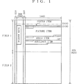
ここで、各アイテムのデータをコンテンツパッケージとしてSDTIフォーマットのペイロード領域に挿入すると共に、SDIフォーマットの符号EAVおよびSAVを付加して、図1に示すようなフォーマットのデータとする。この図1に示すフォーマット(以下「SDTI−CPフォーマット」という)のデータを伝送するときには、SDIフォーマットやSDTIフォーマットと同様に、P/S変換および伝送路符号化が行われて、伝送速度が270Mbps等のシリアルデータとして伝送される。
【0024】
なお、図1において、括弧内の数字はPAL625方式のビデオ信号の数値を示しており、括弧がない数字はNTSC525方式のビデオ信号の数値を示している。以下、NTSC方式についてのみ説明する。
【0025】
図2は、符号EAVおよびアンシラリデータ領域に含まれるヘッダデータ(Header Data)の構成を示している。
【0026】
符号EAVは、3FFh,000h,000h,XYZh(hは16進表示であることを示しており以下の説明でも同様である)とされている。
【0027】
「XYZh」は、ビットb9が「1」に設定されると共に、ビットb0,b1が「0」に設定される。ビットb8はフィールドが第1あるいは第2フィールドのいずれであるかを示すフラグであり、ビットb7は垂直ブランキング期間を示すフラグである。またビットb6は、4ワードのデータがEAVであるかSAVであるかを示すフラグである。このビットb6のフラグは、EAVのときに「1」とされると共にSAVのときに「0」となる。またビットb5〜b2は誤り検出訂正を行うためのデータである。
【0028】
次に、ヘッダデータの先頭には、ヘッダデータ認識用のデータ「ADF(Ancillary data flag)」として、固定パターン000h,3FFh,3FFhが配されている。この固定パターンに続いて、アンシラリデータ領域の属性を示す「DID(Data ID)」および「SDID(Secondary data ID)」が配されている。この「DID」および「SDID」には、その属性がユーザアプリケーションであることを示す固定パターン140h,101hが配されている。
【0029】
「Data Count」は、ヘッダデータのワード数を示すものであり、ワード数は46ワード(22Eh)とされている。このヘッダデータは、図2に示すように「Line Number-0」から「Header CRC1」までのデータで構成されている。
【0030】
「Line Number-0,Line Number-1」は、テレビライン番号を示すものであり、NTSC525方式ではこの2ワードによって1から525まで映像フレームのライン番号が示される。また、PAL方式625方式では1から625までの映像フレームのライン番号が示される。
【0031】
「Line Number-0,Line Number-1」に続いて、「Line Number CRC0,Line Number CRC1」が配されており、この「Line Number CRC0,Line Number CRC1」は、「DID」から「Line Number-1」までの5ワードに対するCRC(cyclic redundancy check codes)の値であり、伝送エラーのチェックに用いられる。
【0032】
「Code & AAI(Authorized address identifier)」では、SAVからEAVまでのペイロード部のワード長がどのような設定とされているか、および送出側や受取側のアドレスがどのようなデータフォーマットとされているか等の情報が示される。
【0033】
「Destination Address」は、データ受取側(送出先)のアドレスであり、「Source Address」は、データ送出側(送出元)のアドレスである。「Source Address」に続く「Block Type」は、ペイロード部がどのような形式とされているか、例えば固定長か可変長かを示すものである。ペイロード部が可変長の形式であるとき、圧縮データが挿入される。ここで、SDTI−CPフォーマットでは、例えば圧縮されたビデオデータを用いてコンテントアイテムを生成したときにフレーム毎にデータ量が異なることから可変長ブロック(Variable Block)が用いられる。このため、SDTI−CPフォーマットでの「Block Type」は固定データ1C1hとされる。
【0034】
「CRC Flag」は、ペイロード部PADの最後の2ワードにCRCが置かれているか否かを示すものである。また、「CRC Flag」に続く「Data extension flag」は、ユーザーデータパケットを拡張しているか否かを示している。
【0035】
「Data extension flag」に続いて4ワードの「Reserved」領域が設けられる、次の「Header CRC 0,Header CRC 1」は、「Code & AAI」から「Reserved3」までに対するCRC(cyclic redundancy check codes)の値であり、伝送エラーのチェックに用いられる。「Check Sum」は、全ヘッダデータに対するCheck Sumコードであり、伝送エラーのチェックに用いられる。
【0036】
次に、映像フレームのペイロード部PADに挿入されるコンテンツパッケージについて、図3を用いて、さらに説明する。図3は、コンテンツパッケージの基本的構成を示している。
【0037】
各コンテンツパッケージは、それぞれが一もしくはそれ以上のエレメントからなる4つまでのアイテムで構成される。この4つのアイテムとは、システム、ピクチャ、オーディオ、補助データの各アイテムである。
【0038】
ピクチャとオーディオのアイテムは、基本的にテレビジョンの直接の構成要素を搬送するストリームエレメントである。これら2つのアイテムは、たびたび専用のストレージもしくは処理機器に送られる。補助データは、サブタイトルやテレテキストデータ等のデータ中心のコンテンツを搬送するために使用され、コンピュータ上で頻繁に作成され、そして処理されてストアされる。
【0039】
ディジタル配送サービスが増加した場合には、補助データタイプは、その数、ボリューム、複雑さにおいて、増えていくものと予想される。最後に、システムアイテムは、タイムスタンプのようなパッケージメタデータ、他の3つのアイテムの各エレメントのためのメタデータ、ダウンストリームパッケージ制御エレメントを通じて、全体としてのパッケージのためのサービスを提供する。ピクチャ、オーディオ、補助データアイテムは、それぞれ、例えば255個までのエレメントで構成できる。
【0040】
図1は、システム、ピクチャ、オーディオ、補助データの4つのアイテムからなるコンテンツパッケージを、映像フレームのペイロード部に挿入したときのデータ構造を示している。
【0041】
図4は、MPEG−2のGOPの例を使用したコンテンツパッケージの配置(斜線部参照)を示している。符号化されたビデオデータの各フレームは、他のデータと共にパッケージ化されて一連のコンテンツパッケージが生成される。そして、SDTIフォーマット上で、各フレームの第1フィールドから第2フィールドへ左から右の順番にスキャンされて転送が行われる。この場合、各フレームのビデオデータは異なる大きさに符号化されるが、符号化された各フレームのビデオデータは、各フレーム区間に対応して伝送される。
【0042】
なお、各コンテンツパッケージはシステムアイテムを含まねばならず、他のアイテムのいずれかによって完結される。システムアイテムは、コンテンツパッケージの開始点を認識するために最初に配されている。すなわち、このシステムアイテムは、NTSC方式では第13ラインより始まり、PAL方式では第9ラインから始まる。また、1つのコンテンツパッケージにおいて、上述した4つのタイプのアイテムのうち、一つのタイプのアイテムしかない場合もある。
【0043】
各アイテムは、図5に示すように、「Separator」で始まり、「End Code」で終わるSDTI可変長ブロックとして構成される。「Separator」は、開始同期符号SAVに続いてすぐに始まる。「Separator」の値は「309h」、「End Code」の値は「30Ah」に設定されている。「Word Count」は「Data Block」のワード数を示しており、「Data Block」が各アイテムのデータである。
【0044】
「Data Type」はパッケージ化されているデータが、どのようなアイテムのデータであるかを示すものである。「Data Type」の値は、例えばシステムアイテムでは「04h」、ピクチャアイテムでは「05h」、オーディオアイテムでは「06h」、補助データアイテムでは「07h」とされる。コンテンツパッケージの始まりは、システムアイテムの「Data Type」コードの検出によって行われる。
【0045】
なお、各SDTI可変長ブロックの入力フォーマットは、10ビットワードの一部をなすビットb0〜b7の8ビットデータである。ビットb8とb9は、「Separator」ワードと「End Code」ワードのために、共に「1」に設定される。「Data Type」、「Word Count」、「Data Block」の各ワード用には、SDTIフォーマット通りに、ビット8がビットb0〜b7の偶数パリティとなり、ビットb9が奇数パリティとなるように設定される。
【0046】
図6は、システムアイテムの構成を示している。「System Item Type」と「Word Count」は、それぞれ上述した可変長ブロックの「Data Type」と「Word Count」に相当する。このシステムアイテムは、ピクチャ、オーディオ、補助データの各アイテムのエレメントのためのメタデータと共に、パッケージメタデータおよびコントロールデータを含んでいる。
【0047】
このシステムアイテムは、7ワードのシステムアイテムヘッダで始まり、SMPTEユニバーサルラベル、タイムスタンプ、パッケージ、ピクチャ、オーディオおよび補助データのメタデータセット、さらにコントロールエレメントが後に続くようにされる。
【0048】
システムアイテムヘッダは、1ワードの「System Item Bitmap」と、1ワードの「Content Package Rate」と、「stream status」フラグ を含む1ワードの「Content Package Type」と、2ワードの「Channel Handle」と、2ワードの「Continuity Count」とからなっている。
【0049】
「System Item Bitmap」を説明する。ビットb7は誤り訂正符号が加えられているか否かを示すフラグであり、「1」とされているときには誤り訂正符号が加えられていることを示している。ビットb6は、「SMPTE Universal Label」の情報があるか否かを示すフラグである。ここで「1」とされているときには、「SMPTE Universal Label」の情報がシステムアイテムに含まれていることを示している。
【0050】
ビットb5およびb4は「Reference Date/Time stamp」、「Current Date/Time stamp」がシステムアイテムにあるか否かを示すフラグである。「Reference Date/Time stamp」では、例えばコンテンツパッケージが最初に作られた時間あるいは日付が示される。「Current Date/Time stamp」では、コンテンツパッケージのデータを最後に修正した時間あるいは日付が示される。
【0051】
ビットb3はピクチャアイテム、ビットb2はオーディオアイテム、ビットb1は補助データアイテムがこのシステムアイテムの後にあるか否かを示すフラグであり、「1」とされているときはそれぞれそのアイテムがこのシステムアイテムの後に存在することを示す。
【0052】
ビットb0は、コントロールエレメントがこのシステムアイテムにあるか否かを示すフラグであり、「1」とされているときはコントロールエレメントが存在することを示す。なお、図示せずもビットb8,b9が上述したように付加されて10ビットのデータとして伝送される。
【0053】
「Content Package Rate」を説明する。ビットb7〜b6は未定義領域(Reserved)であり、ビットb5〜b1では、1倍速動作における1秒当たりのパッケージ数であるパッケージレート(Package Rate)が示される。ビットb0は1.001フラグであり、フラグが「1」に設定されているときは、パッケージレートが1/1.001倍であることが示される。
【0054】
「Content Package Type」を説明する。ビットb7〜b5は、ストリーム内における、当該ピクチャ単位の位置を識別するための「Stream Status」フラグである。この3ビットの「Stream Status」フラグによって、以下の8種類の状態が示される。
0:このピクチャ単位が、プリロール(pre-roll)区間、編集区間、ポストロール(post-roll)区間のいずれの区間にも属さない。
1:このピクチャ単位が、プリロール区間に含まれているピクチャであり、この後に編集区間が続く。
2:このピクチャ単位が、編集区間の最初のピクチャ単位である。
3:このピクチャ単位が、編集区間の中間に含まれているピクチャ単位である。
4:このピクチャ単位が、編集区間の最後のピクチャ単位である。
5:このピクチャ単位が、ポストロール区間に含まれているピクチャ単位である。
6:このピクチャ単位が、編集区間の最初、かつ最後のピクチャ単位である(編集区間のピクチャ単位が1つだけの状態)。
7:未定義
【0055】
また、ビットb4は未定義領域(Reserved)である。ビットb3,b2の「Transfer Mode」では、伝送パケットの伝送モードが示される。また、ビットb1,b0の「Timing Mode」ではタイミングモードが示される。ここで、ビットb3,b2で示される値が「0」のときには同期モード(Synchronous mode)、「1」のときには等時性モード(Isochronous mode)、「2」のときは非同期モード(Asynchronous mode)とされる。ビットb1,b0で示される値が「0」のときには1フレーム分のコンテンツパッケージの伝送を第1フィールドの所定のラインのタイミングで開始するノーマルタイミングモード(Normal timing mode)とされ、「1」のときにはその伝送を第2フィールドの所定のラインのタイミングで開始するアドバンスドタイミングモード(Advanced timing mode)とされ、「2」のときはその伝送を第1および第2フィールドのそれぞれの所定のラインのタイミングで開始するデュアルタイミングモード(Dual timing mode)とされる。
【0056】
「Channel Handle」について説明する。この「Channel Handle」ワードは、複数の番組のコンテンツパッケージが多重化されて伝送される場合に、各番組のコンテンツパッケージを識別するためのものである。この「Channel Handle」ワードの16ビットの値を判別することで、多重化されているコンテンツパッケージをそれぞれ番組毎に分離することができる。
【0057】
「Continuity Count」について説明する。「Continuity Count」は、16ビットのモジュロカウンタである。このカウンタは、ピクチャ単位毎にカウントアップされると共に、それぞれのストリームで独自にカウントされる。したがって、ストリームスイッチャ等によってストリームの切り替えがあるときは、このカウンタの値が不連続となって、切り替え点(編集点)の検出が可能となる。なお、このカウンタは上述したように16ビット(216=65536)のモジュロカウンタであって非常に大きいので、2つの切り替えられるストリームにおいて、切り替え点でのカウンタの値が偶然に一致する確率が限りなく低く、切り替え点の検出のために、実用上充分な精度を提供できる。
【0058】
「Continuity Count」の後には、上述したように「SMPTE Universal Label」、「Reference Date/Time stamp」、「Current Date/Time stamp」が設けられる。さらに、その後に、「Package Metadata Set」、「Picture Metadata Set」、「Audio Metadata Set」、「Auxiliary Metadata Set」がパッケージ化されたアイテムに応じて設けられ、番組タイトル等のコンテンツパッケージの情報や、ピクチャやオーディオあるいは補助データのパッケージ化されているアイテムに関する情報が示される。なお、「Picture Metadata Set」、「Audio Metadata Set」、「Auxiliary Metadata Set」は、対応するアイテムが「System Item Bitmap」のフラグによってコンテンツパッケージに内に含まれることが示されたときに設けられる。
【0059】
さらに、これらの後に「Control Element」を設けることができる。この「Control Element」は、1バイトのエレメントタイプ識別子とそれに続く4バイトのワードカウントとコントロールエレメントデータからなる。
【0060】
上述の「Time stamp」についてされに説明する。この「Time stamp」には17バイトが割り当てられており、最初の1バイトで「Time stamp」であることが識別されると共に、残りの16バイトがデータ領域として用いられる。ここで、データ領域の最初の8バイトは、例えばSMPTE12Mとして規格化されたタイムコード(Time-code)を示しており、後の8バイトは無効データである。
【0061】
図7は、SMPTE−12Mとして規格化されたタイムコードの構成を示している。このタイムコードは、「Frame」、「Seconds」、「Minutes」、「Hours」および4バイトの「Binary Group Data」からなる。
【0062】
「Frame」について説明する。ビットb7はカラーフレームフラグ(Color Frame Flag)であり、このカラーフレームフラグにより第1のカラーフレームであるか第2のカラーフレームであるかが示される。ビットb6はドロップフレームフラグ(Drop Frame Flag)であり、このドロップフレームフラグによりピクチャアイテムに挿入された映像フレームがドロップフレームであるか否かが示される。そして、ビットb5,b4でフレームの10の位、ビットb3〜b0でフレームの1の位が示される。
【0063】
「Seconds」について説明する。ビットb7は、フィールド位相(NTSC)またはバイナリグループ0(PAL)を示している。したがって、NTSC方式の場合には、このビットb7により第1フィールドであるか第2フィールドであるかが示される。そして、ビットb6〜b4で秒の10の位、ビットb3〜b0で秒の1の位が示される。
【0064】
「Minutes」について説明する。ビットb7は、バイナリグループ0(NTSC)またはバイナリグループ2(PAL)を示している。そして、ビットb6〜b4で分の10の位、ビットb3〜b0で分の1の位が示される。
【0065】
「Hours」について説明する。ビットb7は、バイナリグループ1を示している。ビットb6は、バイナリグループ2(NTSC)またはフィールドフェーズ(PAL)を示している。したがって、PAL方式の場合には、このビットb6により第1フィールドであるか第2フィールドであるかが示される。そして、ビットb5,b4で時の10の位、ビットb3〜b0で秒の1の位が示される。
【0066】
また、上述した「Minutes」のビットb7および「Hours」のビットb7,b6の3ビットB0〜B3(PAL方式では、「Seconds」、「Minutes」、「Hours」のビットb7の3ビットFP,B0,B2)によって、「Binary Group Data」の各BG1〜BG8にデータがあるか否かが示される。この「Binary Group Data」では、例えばグレゴリオ暦(Gregorian Calender)やユリウス暦(Julian Calender)での年月日を二桁で表示することができるようになされている。
【0067】
上述した「Metadata Set」について、さらに説明する。図8は、「Metadata Set」の構成を示している。「Metadata Set」は、セット内の「Metadata Block」のワード数を定義する1ワードの「Metadata Count」によって始められる。「00h」のメタデータカウント値は、有効な値であって、「Metadata Block」がないことを示す。この場合、「Metadata Set」は、たった1ワード長のものとなる。
【0068】
図9Aは「Package Metadata Block」の構成を示している。この「Package Metadata Block」は、1ワードの「Metadata Type」で始まり、次いで2ワードの「Word Count」(図9C)が続き、「Metadata」自体で完結する。「Metadata Type」ワードでは、「Metadata」の種類が示される。「Word Count」では、ブロックの終わりまでのワード数(可変長のブロックの「Word Count」に相当)が示される。
【0069】
図9Bは、「Item Metadata Block」の構成を示している。この「Item Metadata Block」は、上述した「Package Metadata Block」と同様に、1ワードの「Metadata Type」で始まり、次いで2ワードの「Word Count」(図9C)が続く。さらに、1ワードの「Element Type」および1ワードの「Element Number」と続き、「Metadata」自体で完結する。「Element Type」および「Element Number」は、ピクチャ、オーディオ、補助データのアイテムの関連するエレメントとの一意的なリンクのための情報である。
【0070】
次に、ピクチャ、オーディオおよび補助データのアイテムの構成を説明する。図10は、これらのアイテムの構成を示している。これらのアイテムは、1ワードの「Item Type」から始まり、4ワードの「Word Count」および1ワードの「Item Header」が続き、その後に「Element Data Block」が続く。「Item Type」は、上述したようにアイテムの種類を示しており、ピクチャアイテムでは、「05h」、オーディオアイテムでは「06h」、補助データアイテムでは「07h」である。「Item Word Count」では、このブロックの終わりまでのワード数(可変長ブロックの「Word Count」に相当)が示される。
【0071】
「Item Header」では、「Element Data Block」のワード数が示される。「Element Data Block」がアイテムのデータ領域とされる。ここで、「Item Header」は8ビットで、「Element Data Block」のワード数を示しているので、「Element Data Block」の数は1〜255の範囲(0は有効でない)となる。
【0072】
「Element Data Block」は、1ワードの「Element Type」から始まり、4ワードの「Element Word Count」および1ワードの「Element Number」が続き、「Element Data」で完結する。「Element Type」および「Element Word Count」により、それぞれ「Element Data」のデータ種類およびデータ量が示される。「Element Word Count」は、SMPTE−305Mで規定されたと同じフォーマットを有し、その値は「Element Number」に対して「1」を加えた「Element Data」ワードの長さである。「Element Number」では、何番目の「Element Data Block」であるかが示される。
【0073】
エレメントの一つであるMPEG−2画像エレメントについて説明する。MPEG−2画像エレメントは、いずれかのプロファイル若しくはレベルのMPEG−2ビデオエレメンタリストリーム(V−ES)である。プロファイルおよびレベルは、デコーダーテンプレートドキュメントで定義される。
【0074】
図11は、SDTI−CPエレメントフレームにおけるMPEG−2 V−ESのフォーマット例を示している。この例は、キー、つまりMPEG−2スタートコードを特定する(SMPTEレコメンデッドプラクティスにしたがった)V−ESビットストリーム例である。MPEG−2 V−ESビットストリームは、単純に同図に示されたようにデータブロックにフォーマットされる。
【0075】
次に、エレメントの一つである8チャネルAES−3エレメントについて説明する。このエレメントは、本来的に8チャネルまでの非圧縮AES−3オーディオデータを搬送するためのものであるが、既にAES−3信号として符号化された圧縮ビットストリームや他の非オーディオデータを搬送することもできる。
【0076】
図12は、8チャネルAES−3エレメントの構成を示している。このエレメントは、「Element Header」、「Audio Sample Count」、「Stream Valid Flags」および「AES-3 Data Area」で構成されている。
【0077】
「Element Header」について説明する。ビットb7は「FVUCP Valid Flag」であり、AES(Audio Engineering Society)で規格化されたAES−3のフォーマットにおいて定義されているFVUCPが、「Data Area」のAES−3フォーマットのオーディオデータで設定されているか否かが示される。ビットb6〜b3は未定義領域(Reserved)であり、ビットb2〜b0で、5フレームシーケンスのシーケンス番号(5-sequence count)が示される。
【0078】
ここで、5フレームシーケンスについて説明する。1フレームが525ラインの走査線で(30/1.001)フレーム/秒のビデオ信号に同期すると共に、サンプリング周波数が48kHzであるオーディオ信号を、ビデオ信号の各フレームのブロック毎に分割すると、1ビデオフレーム当たりのサンプル数は1601.6サンプルとなり整数値とならない。このため、5フレームで8008サンプルとなるように1601サンプルのフレームを2フレーム設けると共に1602サンプルのフレームを3フレーム設けるシーケンスが5フレームシーケンスと呼ばれている。
【0079】
図13は、5フレームシーケンスを示している。すなわち、基準フレームに同期して、例えばシーケンス番号1,3,5のフレームが1602サンプル、シーケンス番号2,4のフレームが1601サンプルとされている。このシーケンス番号が、上述した「Element Header」のビットb2〜b0で示される。
【0080】
「Audio Sample Count」について説明する。この「Audio Sample Count」は、図12に示すように、ビットc15〜c0を用いた0〜65535の範囲内の16ビットのカウンタであり、各チャネルのサンプル数が示される。なお、エレメント内では全てのチャネルが同じ値を有するものである。
【0081】
「Stream Valid Flags」について説明する。この「Stream Valid Flags」では、8チャネルの各ストリームが有効であるか否かが示される。ここで、各チャネルに意味のあるオーディオデータが含まれている場合には、このチャネルに対応するビットが「1」に設定されると共に、それ以外では「0」に設定されて、ビットが「1」に設定されたチャネルのオーディオデータのみが伝送される。
【0082】
「AES-3 Data Area」について説明する。この「Data Area」の「s2〜s0」は8チャネルの各ストリームを識別のためのデータ領域である。「F」はサブフレームの開始を示している。「a23〜a0」はオーディオデータであり、「P,C,U,V」はチャネルステータスやユーザビット、Validityビット、パリティ等である。
【0083】
次に、汎用のデータフォーマット(General Data Format)について説明する。この汎用のデータフォーマットは、全てのフリーフォームデータタイプを搬送するために使用される。しかし、このフリーフォームデータタイプには、ITネイチャ(ワードプロセッシングファイルやハイパーテキスト等)などの特別な補助エレメントタイプは含まれない。
【0084】
次に、メタデータの一つであるMPEG−2画像編集メタデータについて説明する。このメタデータは、編集およびエラーメタデータと、圧縮符号化メタデータと、ソース符号化メタデータとの組み合わせである。これらのメタデータは、主として上述したシステムアイテム、さらには補助データアイテムに挿入することができる。
【0085】
図14A〜Cは、それぞれ、図6に示すシステムアイテムの「Picture Metadata Set」領域に挿入されるMPEG−2画像編集メタデータ内に設けられる「Picture Editing Bitmap」領域と、「Picture Coding」領域と、「MPEG User Bitmap」領域を示している。さらに、このMPEG−2画像編集メタデータには、MPEG−2のプロファイルとレベルを示す「Profile/Level」領域や、SMPTE186−1995で定義されたビデオインデックス情報を設けることも考えられる。
【0086】
図14Aは、1ワードの「Picture Editing Bitmap」を示している。ビットb7およびb6は「Edit flag」であり、編集点情報を示すフラグである。この2ビットのフラグによって、以下の4種類の状態が示される。
00:編集なし
01:編集点が、このフラグが付いているピクチャ単位の前にある(Pre-picture edit)
10:編集点が、このフラグが付いているピクチャ単位の後にある(Post-picture edit)
11:ピクチャ単位が1つだけ挿入され、編集点がこのフラグが付いているピクチャ単位の前と後にある(single frame picture)
【0087】
つまり、ピクチャアイテムに挿入された映像データ(ピクチャ単位)が、編集点の前にあるか、編集点の後にあるか、さらに2つの編集点に挟まれているか、を示すフラグを「Picture Metadata Set」(図6参照)の「Picture Editing Bitmap」領域に挿入する。
【0088】
ビットb5およびb4は、「Error flag」である。この「Error flag」は、ピクチャが修正できないエラーを含んでいる状態にあるか、ピクチャがコンシールエラーを含んでいる状態にあるか、ピクチャがエラーを含んでいない状態にあるか、さらには未知状態にあるかを示す。ビットb3は、「Picture Coding」がこの「Picture Metadata Set」領域にあるか否かを示すフラグである。ここで、「1」とされているときは、「Picture Coding」が含まれていることを示している。
【0089】
ビットb2は、「Profile/Level」があるか否かを示すフラグである。ここで、「1」とされているときは、当該「Metadata Block」に「Profile/Level」が含まれている。この「Profile/Level」は、MPEGのプロファイルやレベルを示すMP@MLやHP@HL等を示す。
【0090】
ビットb1は、「HV Size 」があるか否かを示すフラグである。ここで、「1」とされているときは、当該「Metadata Block」に「HV Size 」が含まれている。ビットb0は、「MPEG User Bitmap」があるか否かを示すフラグである。ここで、「1」とされているときは、当該「Metadata Block」に「MPEG User Bitmap」が含まれている。
【0091】
図14Bは、1ワードの「Picture Coding」の構成を示している。ビットb7には「Closed GOP」が設けられる。この「Closed GOP」は、MPEG圧縮したときのGOP(Group Of Picture)がClosed GOPか否かを示す。
【0092】
ビットb6には、「Broken Link」が設けられる。この「Broken Link」は、デコーダ側の再生制御に使用されるフラグである。すなわち、MPEGの各ピクチャは、Bピクチャ、Bピクチャ、Iピクチャ・・・のように並んでいるが、編集点があって全く別のストリームをつなげたとき、例えば切り替え後のストリームのBピクチャが切り替え前のストリームのPピクチャを参照してデコードされるというおそれがある。このフラグをセットすることで、デコーダ側で上述したようなデコードがされないようにできる。
【0093】
ビットb5〜b3には、「Picture Coding Type」が設けられる。この「Picture Coding Type」は、ピクチャがIピクチャであるか、Bピクチャであるか、Pピクチャであるかを示すフラグである。ビットb2〜b0は、未定義領域(Reserved)である。
【0094】
図14Cは、1ワードの「MPEG User Bitmap」の構成を示している。ビットb7には、「History data」が設けられている。この「History data」は、前の世代の符号化に必要であった、例えば量子化ステップ、マクロタイプ、動きベクトル等の符号化データが、例えば「Metadata Block」の「Metadata」内に存在するユーザデータ領域に、History dataとして挿入されているか否かを示すフラグである。ビットb6には、「Anc data」が設けられている。この「Anc data」は、
アンシラリ領域に挿入されたデータ(例えば、MPEGの圧縮に必要なデータ等)を、上述のユーザデータ領域に、Anc dataとして挿入されているか否かを示すフラグである。
【0095】
ビットb5には、「Video index」が設けられている。この「Video index」は、Video index領域内に、Video index情報が挿入されているか否かを示すフラグである。このVideo index情報は15バイトのVideo index領域内に挿入される。この場合、5つのクラス(1.1、1.2、1.3、1.4および1.5の各クラス)毎に挿入位置が決められている。例えば、1.1クラスのVideo index情報は最初の3バイトに挿入される。
【0096】
ビットb4には、「Picture order」が設けられている。この「Picture order」は、MPEGストリームの各ピクチャの順序を入れ替えたか否かを示すフラグである。なお、MPEGストリームの各ピクチャの順序の入れ替えは、多重化のときに必要となる。
【0097】
ビットb3,b2には、「Timecode 2」、「Timecode 1」が設けられている。この「Timecode 2」、「Timecode 1」は、Timecode 2,1の領域に、VITC(Vertical Interval Time Code)、LTC(Longitudinal Time Code)が挿入されているか否かを示すフラグである。ビットb1,b0には、「H-Phase」、「V-Phase」が設けられている。この「H-Phase」、「V-Phase」は、エンコード時にどの水平画素、垂直ラインからエンコードされているか、つまり実際に使われる枠の情報がユーザデータ領域にあるか否かを示すフラグである。
【0098】
次に、メタデータの一つであるオーディオ編集メタデータについて説明する。このメタデータは、編集およびエラーメタデータおよびソース符号化メタデータの組み合わせである。これらのメタデータは、主として上述したシステムアイテム、さらには補助データアイテムに挿入することができる。
【0099】
図15A〜Dは、それぞれ図6に示すシステムアイテムの「Audio Metadata Set」領域に挿入されるオーディオ編集メタデータ内に設けられる「Field/Frame flags」領域と、「Audio Editing Bitmap」領域と、「CS Valid Bitmap」領域と、「Channel Status Data」領域を示している。
【0100】
ここで、有効とされているオーディオのチャネル数は、上述した図12の「Stream Valid Flags」によって判別することができる。また「Stream Valid Flags」が「1」に設定されている場合には、「Audio Editing Bitmap」が有効となる。
【0101】
図15Aは、1ワードの「Filed/Frame flags」を示している。ビットb7〜b0のそれぞれ第1〜第8のチャネルのオーディオデータに対応し、「0」であるときはフレーム単位でデータがパッキングされていることを示し、「1」であるときはフィールド単位でデータがパッキングされていることを示す。
【0102】
図15Bは、1ワードの「Audio Editing Bitmap」を示している。ビットb7,b6の「First edit flag」は第1フィールドの編集状況に関する情報を示し、ビットb5,b4の「First edit flag」は第1フィールドの編集状況に関する情報を示す。ビットb3,b2は、「Error flag」である。この「Error flag」では、修正できないようなエラーが発生しているか否か等が示される。ビットb1,b0は、未定義領域(Reserved)である。
【0103】
図15Cは、1ワードの「CS Valid Bitmap」を示している。この「CS Valid Bitmap」は、図15Dに示すn(n=6,14,18あるいは22)バイトの「Channel Status Data」のヘッダであり、データブロック内で24のチャネルステータスワードのどれが存在しているかが示される。ここで、ビットb7の「CS Valid1」は、「Channel Status Data」の0から5バイトまでにデータがあるか否かを示すフラグである。同様に、ビットb6〜b4の「CS Valid2」〜「CS Valid4」は、それぞれ、「Channel Status Data」の6から13バイト、14から17バイト、18から21バイトまでにデータがあるか否かを示すフラグである。
【0104】
なお、「Channel Status Data」は24バイト分とされており、最後から2番目の22バイトのデータによって0から21バイトまでにデータがあるか否かが示されると共に、最後の23バイトのデータが、0から22バイトまでのCRCとされる。
【0105】
図16は、上述したSDTI−CPフォーマットによるストリーム(以下、「SDTI−CPトリーム」という)の伝送系の一例を示している。この伝送系100は、VTRやサーバ等からなるストレージデバイス101と、SDTI−CPインタフェース102と、伝送路104上に配置されたSDTI−CPストリームスイッチャ103とを有して構成されている。
【0106】
ストレージデバイス101には、複数のコンテンツパッケージが蓄積される。各コンテンツパッケージは、上述したようにシステムアイテム、ピクチャアイテム、オーディオアイテム、補助データアイテム等の複数のアイテムからなっている。ストレージデバイス101より順次出力されるコンテンツパッケージはSDTI−CPインタフェース102に供給される。SDTI−CPインタフェース102は、各コンテンツパッケージをSDTIフォーマットの各映像フレームの伝送パケットのペイロード部に挿入し(図1参照)、その伝送パケットを伝送路104に送出する。なお、このようにSDTI−CPフォーマットによる伝送データ(SDTI−CPストリーム)を伝送するときは、P/S変換および伝送路符号化が行われた後に、伝送速度が270Mbpsのシリアルデータとして伝送される。
【0107】
また、伝送路104より送られてくるSDTI−CPストリームは、SDTI−CPインタフェース102に供給される。SDTI−CPインタフェース102は、このSDTI−CPストリームを受信し、各映像フレームの伝送パケットのペイロード部に挿入されている各コンテンツパッケージを抽出し、これをストレージデバイス101に順次供給する。ストレージデバイス101は、SDTI−CPインタフェース102より順次送られてくるコンテンツパッケージを記録媒体に順次蓄積していく。
【0108】
なお、ストレージデバイス101は、システムアイテム、ピクチャアイテム、オーディオアイテム、補助データアイテム等からなるコンテンツパッケージを蓄積する代わりに、MPEGビデオデータやオーディオデータ、さらにはメタデータ自体を蓄積するようにしてもよい。
【0109】
この場合、ストレージデバイス101より各映像フレーム毎のビデオデータ、オーディオデータ、メタデータ等が出力されてSDTI−CPインタフェース102に供給される。そして、SDTI−CPインタフェース102は、それら各データよりシステムアイテム、ピクチャアイテム、オーディオアイテム、補助データアイテム等を作成した後にパッキングして各映像フレームのコンテンツパッケージを得、さらに各コンテンツパッケージをSDTIフォーマットの各映像フレームの伝送パケットのペイロード部に挿入し、その伝送パケットを伝送路104に送出する。
【0110】
またこの場合、伝送路104よりSDTI−CPストリームを受信したSDTI−CPインタフェース102は、各映像フレームの伝送パケットのペイロード部に挿入されている各コンテンツパッケージを抽出し、さらにそのコンテンツパッケージを構成するシステムアイテム、ピクチャアイテム、オーディオアイテム、補助データアイテム等のアイテムよりビデオデータ、オーディオデータ、メタデータ等のデータを得て、これをストレージデバイス101に順次供給する。ストレージデバイス101では、SDTI−CPインタフェース102より順次送られてくるビデオデータ、オーディオデータ、メタデータ等のデータが蓄積される。
【0111】
また、図16に示す伝送系におけるストリームスイッチャ103はマトリックススイッチャであり、このストリームスイッチャ103により、SDTI−CPストリームの切り替えが行われる。このSDTI−CPストリームの切り替えは、垂直同期(V−sync)区間、具体的にはNTSC525方式で第10ライン、PAL625方式では第6ラインで切り替えが行われる。
【0112】
次に、VTR編集を行う場合について説明する。図17は、VTR編集を行う場合における伝送系の一例を示している。この伝送系200は、再生側のVTR201AおよびSDTI−CPインタフェース202Aと、記録側のVTR201BおよびSDTI−CPインタフェース202Bとが、伝送路203で接続されて構成されている。
【0113】
この場合、VTR201Aで再生されるコンテンツパッケージもしくはビデオデータ、オーディオデータ、メタデータ等のデータがSDTI−CPインタフェース202Aに供給され、このSDTI−CPインタフェース202Aより伝送路203にSDTI−CPストリームが送出される。
【0114】
ここで、上述したように、システムアイテム(図6参照)の「Content Package Type」ワードのビットb7〜b5は、ストリーム内における、当該ピクチャ単位の位置を識別するための「Stream Status」フラグとされている。SDTI−CPインタフェース202Aより出力されるSDTI−CPストリーム内の各ピクチャ単位毎の3ビットの「Stream Status」フラグは、編集区間に対応して設定されている。
【0115】
図18は、フラグ設定の一例を示している。プリロール区間SPRでは、各ピクチャ単位のフラグが「1」に設定されている。編集区間SEDでは、最初のピクチャ単位のフラグが「2」に設定され、最後のピクチャ単位のフラグが「4」に設定され、さらに中間のピクチャ単位のフラグが「3」に設定されている。また、ポストロール区間SPOでは、各ピクチャ単位のフラグが「5」に設定されている。
【0116】
図19は、フラグ設定の他の例を示している。プリロール区間SPRおよびポストロール区間SPOにおけるフラグの設定は図18に示す例と同じであるが、編集区間SEDには一つのピクチャ単位しかないことから、このピクチャ単位のフラグは「6」に設定されている。
【0117】
図17の伝送系において、再生側のSDTI−CPインタフェース202Aより出力されるSDTI−CPストリームは、伝送路203を介して、記録側のSDTI−CPインタフェース202Bに供給される。このSDTI−CPインタフェース202Bは、そのSDTI−CPストリームを受信し、各映像フレームの伝送パケットのペイロード部に挿入されている各コンテンツパッケージを抽出し、このコンテンツパッケージ、もしくはそのコンテンツパッケージに含まれるビデオデータ、オーディオデータ、メタデータ等のデータを、VTR201Bに順次供給する。
【0118】
そして、VTR201Bは、上述した3ビットの「Stream Status」フラグの設定に基づいて、現在のピクチャ単位が、プリロール区間SPRに属するか、編集区間SEDに属するか、ポストロール区間SPOに属するかを判断して、記録制御をする。すなわち、図20に示すように、VTR(A)[VTR201A]側からのストリームがプリロール区間SPRに入ると、VTR(B)[VTR201B]ではテープ駆動系等の動作が開始され、サーボ等の同期がとられる。そして、VTR(A)側からのストリームが編集区間SEDに入ると、VTR(B)では記録が開始される。さらに、VTR(A)側からのストリームが編集区間SEDを終了し、ポストロール区間SPOに入ると、VTR(B)ではテープ駆動系等の動作が停止される。これにより、VTR編集が良好に行われる。
【0119】
なお、上述実施の形態においては、ピクチャ単位がフレーム単位である例を示したが、ピクチャ単位はそれに限定されるものでなく、フィールド単位、あるいはその他の単位であるものにも、この発明を同様に適用することができる。
【0120】
以上説明したように、この発明においては、受信された伝送パケットより、映像データのピクチャ単位でストリーム情報を持つ付属データと、映像データおよび/または音声データからなる主データとが抽出され、ストリーム情報に基づいて、主データの記録制御が行われる。例えば、プリロール区間でVTRのテープ駆動系等の動作を開始させてサーボ等の同期をとり、編集区間で主データの記録を行い、その後のポストロール区間でVTRのテープ駆動系等の動作を停止させる。したがって、この発明により、VTR編集を良好に行うことができる。
【0121】
産業上の利用可能性
以上のように、この発明に係るデータ伝送方法および装置、並びにデータ受信方法および装置は、動画像信号および音声信号等を伝送路を介して送信側から受信側に伝送するテレビ会議システム、テレビ電話システム、放送用機器などに適用して好適である。
【図面の簡単な説明】
図1は、SDTI−CPフォーマットを説明するための図である。図2は、SDTI−CPフォーマットのアンシラリデータ部内のヘッダの構成を示す図である。図3は、コンテンツパッケージの基本的構成を示す図である。図4は、MPEG−2のGOPの例を使用したコンテンツパッケージの配置を示す図である。図5は、SDTI可変長ブロックの構成を示す図である。図6は、システムアイテムの構成を示す図である。図7は、SMPTE−12Mとして規格されたタイムコードの構成を示す図である。図8は、メタデータセットの構成を示す図である。図9A〜図9Cは、「Item Metadata Block」の構成を示す図である。図10は、ピクチャ、オーディオ、補助データのアイテムの構成を示す図である。図11は、SDTI−CPエレメントフレームにおけるMPEG−2 V−ESのフォーマット例を示す図である。図12は、8チャネルAES−3エレメントの構成を示す図である。図13は、5フレームシーケンスを説明するための図である。図14A〜図14Cは、MPEG−2画像編集メタデータを説明するための図である。図15A〜図15Dは、オーディオ編集メタデータを説明するための図である。図16は、SDTI−CPストリームの伝送系の一例を示すブロック図である。図17は、VTR編集を行う場合における伝送系の一例を示すブロック図である。図18は、「Stream Status」フラグの設定の一例を示す図である。図19は、「Stream Status」フラグの設定の他の例を示す図である。図20は、「Stream Status」フラグを使用したVTR編集の動作を説明するための図である。[0001]
Technical field
The present invention is a data transmission method suitable for application when transmitting video data, audio data, other metadata, etc. , De Data transmission equipment , Data receiving method, data receiving apparatus, data recording method and data recording apparatus About.
[0002]
Background art
The SDI (Serial Digital Interface) format is standardized by SMPTE-259M of SMPTE (Society of Motion Picture and Television Engineers) which issues standards for television engineering and video engineering. This SDI format is basically a signal standard for the D-1 format or D-2 format, which is a digital signal standard.
[0003]
In this SDI format, only limited media data can be transmitted. Specifically, as media that can be transmitted, video data has one channel and baseband audio data has about eight channels. Therefore, the SDI format is not suitable for multimedia or multichannel.
[0004]
The SDTI (Serial Data Transport Interface) format is standardized by SMPTE-SMPTE-305M. The SDTI format is suitable for multimedia or multi-channel use while taking advantage of the SDI format and partially maintaining commonality with the SDI format. The SDTI format is a standard for transmitting a baseband signal, and transmits an end synchronization code (EAV: End of Active Video) and a start synchronization code (SAV: Start of Active Video) together.
[0005]
That is, in the SDTI format, each one-line section of a video frame is divided into an area where EAV is inserted, an auxiliary data area where ancillary data is inserted (ancillary data section ANC), an area where SAV is inserted, A serial digital transfer interface transmission packet composed of a payload area into which video data and audio data are inserted is transmitted.
[0006]
It is conceivable to use such a transmission of a stream (SDTI stream) in the SDTI format in VTR editing. In VTR editing, an SDTI stream is transmitted from the playback VTR side to the recording VTR side.
[0007]
By the way, the VTR uses a servo motor for the tape drive system and the like, and cannot be operated immediately at the editing point. For synchronization of the servo, etc., a certain amount of time is required before the editing In (In) point. A pre-roll section, which is a run-up section for preparation, is required. Similarly, since the VTR cannot suddenly stop the tape drive system or the like, a post-roll section is required after the editing Out point.
[0008]
Therefore, in the VTR editing described above, the stream transmitted from the playback VTR side to the recording VTR side belongs to the pre-roll section before the editing section, the editing section, or the post-roll section after the editing section. It has become necessary to have stream information indicating whether it belongs.
[0009]
An object of the present invention is to enable VTR editing performed by transmitting a stream from the playback VTR side to the recording VTR side, for example.
[0010]
Disclosure of the invention
The data transmission method according to the present invention is a section of each line of a video frame. But An end synchronization code area into which an end synchronization code is inserted, an auxiliary data area into which auxiliary data is inserted, a start synchronization code area into which a start synchronization code is inserted, and main data including video data and / or audio data. A serial digital transfer interface transmission packet consisting of a payload area to be inserted Transmit from the playback side to the recording side, Attached to the payload area is stream information indicating whether the picture unit belongs to the pre-roll section before the editing section, the editing section, and the post-roll section after the editing section, in units of pictures of the video data A first step of inserting the first data including the data and the second data including the main data; and serially converting the transmission packet in which the first data and the second data are inserted in the payload area. And a second step of transmitting The stream side is extracted on the recording side that has received the transmission packet, and when the picture unit enters the pre-roll section, the operation is started to synchronize, and when the picture unit enters the editing section, the recording is started. Stop operation when entering the post-roll section Is.
[0011]
For example, the stream information indicating that a picture unit belongs to the editing section further includes whether the picture unit is the first picture unit of the editing section, the middle picture unit of the editing section, or the last of the editing section. This indicates whether the unit is a picture unit or the first and last picture unit of the editing section.
[0012]
Also, the data transmission device according to the present invention is a section of each line of a video frame. But An end synchronization code area into which an end synchronization code is inserted, an auxiliary data area into which auxiliary data is inserted, a start synchronization code area into which a start synchronization code is inserted, and main data including video data and / or audio data. A serial digital transfer interface transmission packet consisting of a payload area to be inserted Transmit from the playback side to the recording side, Attached to the payload area is stream information indicating whether the picture unit belongs to the pre-roll section before the editing section, the editing section, and the post-roll section after the editing section, in units of pictures of the video data Means for inserting first data including data and second data including the main data, and a transmission packet in which the first data and the second data are inserted into the payload area are serially converted and transmitted. With means Stream information is extracted on the recording side that receives the transmission packet, and when the picture unit enters the pre-roll section, the operation is started to synchronize, and when the picture unit enters the editing section, recording is started, and the picture unit is posted. Stop operation when entering roll section Is.
[0013]
In the present invention, first data including attached data having stream information and second data including main data including video data and / or audio data are inserted into the payload area. Therefore, on the receiving side, for example, the operation of the tape drive system of the recording VTR can be controlled using the stream information, so that VTR editing is possible.
[0014]
The data receiving method according to the present invention is a section of each line of a video frame. But The end synchronization code area into which the end synchronization code is inserted, the auxiliary data area into which auxiliary data is inserted, the start synchronization code area into which the start synchronization code is inserted, and main data consisting of video data and / or audio data Is inserted into the payload area, and in the payload area, In the picture unit of the video data, there is included ancillary data having stream information indicating whether the picture unit belongs to the pre-roll section before the editing section, the editing section, and the post-roll section after the editing section. 1 Data and Second data including main data and Is inserted The A first step of receiving a serial digital transfer interface transmission packet; and a second step of extracting main data and auxiliary data from the received transmission packet. Then, based on the stream information in the attached data extracted from the transmission packet, when the picture unit enters the pre-roll section, the operation is started and synchronized, and when the picture unit enters the edit section, the recording is started, and the picture unit Stops when it enters the postroll section Is.
[0015]
In addition, the data receiving device according to the present invention is a section of one line of a video frame. But The end synchronization code area into which the end synchronization code is inserted, the auxiliary data area into which auxiliary data is inserted, the start synchronization code area into which the start synchronization code is inserted, and main data consisting of video data and / or audio data Is inserted into the payload area, and in the payload area, In the picture unit of the video data, there is included ancillary data having stream information indicating whether the picture unit belongs to the pre-roll section before the editing section, the editing section, and the post-roll section after the editing section. 1 Data and Second data including main data and Is inserted The Means for receiving a transmission packet of the serial digital transfer interface, and means for extracting main data and auxiliary data from the received transmission packet Based on the stream information in the attached data extracted from the transmission packet, when the picture unit enters the pre-roll section, the operation is started to synchronize, and when the picture unit enters the editing section, the recording is started. Stop operation when entering the post-roll section Is.
[0016]
In the present invention, attached data having stream information in units of pictures of video data and main data composed of video data and / or audio data are extracted from the received transmission packet, and based on the stream information, main data of the main data is extracted. Recording control is performed. For example, the operation of the tape drive system of the VTR is started in the pre-roll section, the servo is synchronized, the main data is recorded in the edit section, and the operation of the tape drive system of the VTR in the subsequent post-roll section. Is stopped. Thereby, VTR editing becomes possible.
[0017]
BEST MODE FOR CARRYING OUT THE INVENTION
Hereinafter, embodiments of the present invention will be described with reference to the drawings. In the present embodiment, data such as video and audio material is packaged to generate each content item (for example, a picture item or an audio item), and information about each content item or Metadata related to each content is packaged to generate one content item (System Item), and each of these content items is set as a content package. Furthermore, a transmission packet is generated from the content package and transmitted using a serial digital transfer interface.
[0018]
In this serial digital transfer interface, for example, SMPTE-259M “10-bit 4: 2: 2 Component and 4fsc Composite Digital Signals-Serial Digital Interface” (hereinafter referred to as “Serial Digital Interface SDI (Serial Digital Interface) format) standardized by SMPTE. The above-mentioned content package is transmitted using a digital signal serial transmission format of "" and a standard SMPTE-305M "Serial Data Transport Interface" (hereinafter referred to as "SDTI format") for transmitting packetized digital signals. It is.
[0019]
When the SDI format standardized by SMPTE-259M is placed in a video frame, the
[0020]
For each line, 4 words from the first word to the fourth word indicate the end of the active video area of 1440 words, which is the area of the video signal, and are used to separate the active video area and the ancillary data area described later. It is used as an area for storing a code EAV (End of Active Video).
[0021]
For each line, 268 words from the fifth word to the 272nd word are used as an ancillary data area, and header information and the like are stored. Four words from the 273rd word to the 276th word indicate the start of the active video area, and are used as an area for storing a code SAV (Start of Active Video) for separating the active video area and the ancillary data area. , The 277th word and after are the active video area.
[0022]
In the SDTI format, the above active video area is used as the payload area, and the codes EAV and SAV indicate the end and start of the payload area.
[0023]
Here, the data of each item is inserted into the payload area of the SDTI format as a content package, and the codes EAV and SAV of the SDI format are added to obtain data of the format shown in FIG. When data in the format shown in FIG. 1 (hereinafter referred to as “SDTI-CP format”) is transmitted, P / S conversion and transmission path coding are performed as in the SDI format and SDTI format, and the transmission rate is 270 Mbps. Etc. are transmitted as serial data.
[0024]
In FIG. 1, the numbers in parentheses indicate the numerical values of the PAL625 video signals, and the numbers without the parentheses indicate the numerical values of the NTSC525 video signals. Only the NTSC system will be described below.
[0025]
FIG. 2 shows a configuration of header data included in the code EAV and the ancillary data area.
[0026]
Reference sign EAV is 3FFh, 000h, 000h, XYZh (h indicates hexadecimal display, and the same applies in the following description).
[0027]
In “XYZh”, bit b9 is set to “1”, and bits b0 and b1 are set to “0”. Bit b8 is a flag indicating whether the field is the first or second field, and bit b7 is a flag indicating the vertical blanking period. Bit b6 is a flag indicating whether 4-word data is EAV or SAV. The flag of bit b6 is “1” when EAV and “0” when SAV. Bits b5 to b2 are data for error detection and correction.
[0028]
Next, fixed
[0029]
“Data Count” indicates the number of words of the header data, and the number of words is 46 words (22Eh). As shown in FIG. 2, this header data is composed of data from “Line Number-0” to “Header CRC1”.
[0030]
“Line Number-0, Line Number-1” indicates a TV line number. In the
[0031]
Following “Line Number-0, Line Number-1”, “Line Number CRC0, Line Number CRC1” are arranged. This “Line Number CRC0, Line Number CRC1” is changed from “DID” to “Line Number- CRC (cyclic redundancy check codes) value for 5 words up to “1”, which is used to check transmission errors.
[0032]
In “Code & AAI (Authorized address identifier)”, what is the setting of the word length of the payload part from SAV to EAV, and what data format is the address of the sending side or receiving side Etc. are shown.
[0033]
“Destination Address” is an address on the data receiving side (sending destination), and “Source Address” is an address on the data sending side (sending source). “Block Type” following “Source Address” indicates what format the payload portion is in, for example, fixed length or variable length. When the payload portion has a variable length format, compressed data is inserted. Here, in the SDTI-CP format, for example, when a content item is generated using compressed video data, a variable length block (Variable Block) is used because a data amount is different for each frame. Therefore, “Block Type” in the SDTI-CP format is fixed data 1C1h.
[0034]
“CRC Flag” indicates whether or not a CRC is placed in the last two words of the payload part PAD. Further, “Data extension flag” following “CRC Flag” indicates whether or not the user data packet is extended.
[0035]
Following the “Data extension flag”, a “Reserved” area of 4 words is provided. The next “
[0036]
Next, the content package inserted into the payload part PAD of the video frame will be further described with reference to FIG. FIG. 3 shows a basic configuration of the content package.
[0037]
Each content package consists of up to four items, each consisting of one or more elements. These four items are system, picture, audio, and auxiliary data items.
[0038]
Picture and audio items are basically stream elements that carry the direct components of television. These two items are often sent to dedicated storage or processing equipment. Auxiliary data is used to carry data-centric content such as subtitles and teletext data, and is frequently created, processed and stored on a computer.
[0039]
As digital delivery services increase, ancillary data types are expected to increase in number, volume and complexity. Finally, system items provide services for the package as a whole through package metadata such as timestamps, metadata for each of the other three item elements, and downstream package control elements. Each picture, audio, and auxiliary data item can be composed of, for example, up to 255 elements.
[0040]
FIG. 1 shows a data structure when a content package consisting of four items of system, picture, audio, and auxiliary data is inserted into a payload portion of a video frame.
[0041]
FIG. 4 shows the arrangement of content packages (see the shaded area) using the MPEG-2 GOP example. Each frame of encoded video data is packaged with other data to generate a series of content packages. Then, on the SDTI format, scanning is performed from the first field to the second field of each frame in order from left to right. In this case, the video data of each frame is encoded in different sizes, but the encoded video data of each frame is transmitted corresponding to each frame section.
[0042]
Each content package must include a system item and is completed by one of the other items. The system item is initially arranged to recognize the starting point of the content package. That is, this system item starts from the 13th line in the NTSC system and starts from the 9th line in the PAL system. In addition, in one content package, there may be only one type of item among the four types of items described above.
[0043]
As shown in FIG. 5, each item is configured as an SDTI variable length block that starts with “Separator” and ends with “End Code”. “Separator” starts immediately following the start synchronization code SAV. The value of “Separator” is set to “309h”, and the value of “End Code” is set to “30Ah”. “Word Count” indicates the number of words of “Data Block”, and “Data Block” is data of each item.
[0044]
“Data Type” indicates what kind of item data the packaged data is. The value of “Data Type” is, for example, “04h” for system items, “05h” for picture items, “06h” for audio items, and “07h” for auxiliary data items. The beginning of the content package is done by detecting the “Data Type” code of the system item.
[0045]
Note that the input format of each SDTI variable length block is 8-bit data of bits b0 to b7 forming a part of a 10-bit word. Bits b8 and b9 are both set to "1" for the "Separator" word and the "End Code" word. For each word of “Data Type”, “Word Count”, and “Data Block”,
[0046]
FIG. 6 shows the configuration of the system item. “System Item Type” and “Word Count” correspond to “Data Type” and “Word Count” of the variable length block described above, respectively. This system item includes package metadata and control data, as well as metadata for elements of picture, audio, and auxiliary data items.
[0047]
This system item begins with a 7-word system item header, followed by a SMPTE universal label, timestamp, package, picture, audio and ancillary data metadata set, followed by control elements.
[0048]
The system item header consists of 1 word “System Item Bitmap”, 1 word “Content Package Rate”, 1 word “Content Package Type” including “stream status” flag, 2 words “Channel Handle” It consists of two words “Continuity Count”.
[0049]
Explain "System Item Bitmap". Bit b7 is a flag indicating whether or not an error correction code is added. When it is set to “1”, it indicates that an error correction code is added. Bit b6 is a flag indicating whether or not there is information of “SMPTE Universal Label”. When “1” is set here, it indicates that the information of “SMPTE Universal Label” is included in the system item.
[0050]
Bits b5 and b4 are flags indicating whether or not “Reference Date / Time stamp” and “Current Date / Time stamp” are in the system item. “Reference Date / Time stamp” indicates, for example, the time or date when the content package was first created. “Current Date / Time stamp” indicates the time or date when the content package data was last modified.
[0051]
Bit b3 is a picture item, bit b2 is an audio item, bit b1 is a flag indicating whether or not an auxiliary data item follows this system item, and when it is set to “1”, the item is this system item. It is present after.
[0052]
Bit b0 is a flag indicating whether or not the control element is in this system item. When it is set to “1”, it indicates that the control element exists. Although not shown, bits b8 and b9 are added as described above and transmitted as 10-bit data.
[0053]
Explain “Content Package Rate”. Bits b7 to b6 are undefined areas (Reserved), and bits b5 to b1 indicate a package rate which is the number of packages per second in the single speed operation. Bit b0 is a 1.001 flag, and when the flag is set to “1”, it indicates that the package rate is 1 / 1.001 times.
[0054]
Explain “Content Package Type”. Bits b7 to b5 are “Stream Status” flags for identifying the position of the picture unit in the stream. The following eight types of states are indicated by the 3-bit “Stream Status” flag.
0: This picture unit does not belong to any of the pre-roll section, the edit section, and the post-roll section.
1: This picture unit is a picture included in the pre-roll section, followed by the editing section.
2: This picture unit is the first picture unit in the editing section.
3: This picture unit is a picture unit included in the middle of the editing section.
4: This picture unit is the last picture unit in the editing section.
5: This picture unit is a picture unit included in the post-roll section.
6: This picture unit is the first and last picture unit in the editing section (a state in which there is only one picture unit in the editing section).
7: Undefined
[0055]
Bit b4 is an undefined area (Reserved). In “Transfer Mode” of bits b3 and b2, the transmission mode of the transmission packet is indicated. The timing mode is indicated by “Timing Mode” of bits b1 and b0. Here, when the value indicated by the bits b3 and b2 is “0”, the synchronous mode (Synchronous mode), when “1”, the isochronous mode (Asynchronous mode), and when “2”, the asynchronous mode (Asynchronous mode). It is said. When the values indicated by the bits b1 and b0 are “0”, the transmission of the content package for one frame is set to the normal timing mode in which transmission of the content package for one frame is started at the timing of the predetermined line of the first field. Sometimes, the transmission is in an advanced timing mode in which the transmission is started at the timing of a predetermined line in the second field. When the transmission timing is “2”, the transmission is performed at the timing of each predetermined line in the first and second fields. Dual timing mode starting at
[0056]
“Channel Handle” will be described. The “Channel Handle” word is used to identify the content package of each program when the content packages of a plurality of programs are multiplexed and transmitted. By discriminating the 16-bit value of this “Channel Handle” word, the multiplexed content packages can be separated for each program.
[0057]
“Continuity Count” will be described. “Continuity Count” is a 16-bit modulo counter. This counter is counted up for each picture unit and is uniquely counted for each stream. Therefore, when the stream is switched by a stream switcher or the like, the value of this counter becomes discontinuous, and the switching point (editing point) can be detected. Note that this counter has 16 bits (2 16 = 65536) and is very large, the probability that the counter value at the switching point coincides by chance is extremely low in the two switched streams, which is practically sufficient for detecting the switching point. Accurate accuracy can be provided.
[0058]
After “Continuity Count”, “SMPTE Universal Label”, “Reference Date / Time stamp”, and “Current Date / Time stamp” are provided as described above. Furthermore, after that, “Package Metadata Set”, “Picture Metadata Set”, “Audio Metadata Set”, “Auxiliary Metadata Set” are provided according to the packaged items, information on content packages such as program titles, Information about the packaged item of picture, audio or auxiliary data is shown. Note that “Picture Metadata Set”, “Audio Metadata Set”, and “Auxiliary Metadata Set” are provided when the corresponding item is indicated in the content package by the flag of “System Item Bitmap”.
[0059]
Furthermore, a “Control Element” can be provided after these. This “Control Element” is composed of a 1-byte element type identifier followed by a 4-byte word count and control element data.
[0060]
The above-described “Time stamp” will be described in detail. This “Time stamp” is assigned 17 bytes. The first 1 byte identifies the “Time stamp”, and the remaining 16 bytes are used as a data area. Here, the first 8 bytes of the data area indicate a time code (Time-code) standardized as, for example, SMPTE12M, and the subsequent 8 bytes are invalid data.
[0061]
FIG. 7 shows the structure of a time code standardized as SMPTE-12M. This time code is composed of “Frame”, “Seconds”, “Minutes”, “Hours”, and 4-byte “Binary Group Data”.
[0062]
“Frame” will be described. Bit b7 is a color frame flag, which indicates whether the color frame flag is the first color frame or the second color frame. Bit b6 is a drop frame flag, which indicates whether or not the video frame inserted into the picture item is a drop frame. Bits b5 and b4 indicate the tenth position of the frame, and bits b3 to b0 indicate the first position of the frame.
[0063]
“Seconds” will be described. Bit b7 indicates field phase (NTSC) or binary group 0 (PAL). Therefore, in the case of the NTSC system, this bit b7 indicates whether it is the first field or the second field. Bits b6 to b4 indicate the tenths of the second, and bits b3 to b0 indicate the ones of the second.
[0064]
Explain “Minutes”. Bit b7 indicates binary group 0 (NTSC) or binary group 2 (PAL). The bits b6 to b4 indicate the tenths of the minute, and the bits b3 to b0 indicate the ones of the minutes.
[0065]
Explain about "Hours". Bit b7 indicates
[0066]
Further, the above-described “Minutes” bit b7 and “Hours” bits b7 and b6, 3 bits B0 to B3 (in the PAL system, “Seconds”, “Minutes”, “Hours” bit b7, 3 bits FP, B0) , B2) indicates whether or not there is data in each of BG1 to BG8 of "Binary Group Data". In this "Binary Group Data", for example, the date in the Gregorian calendar (Gregorian Calender) or the Julian calendar (Julian Calender) can be displayed in two digits.
[0067]
The “Metadata Set” described above will be further described. FIG. 8 shows the configuration of “Metadata Set”. A “Metadata Set” is started by a one-word “Metadata Count” that defines the number of words of “Metadata Block” in the set. The metadata count value of “00h” is a valid value and indicates that “Metadata Block” is not present. In this case, the “Metadata Set” is only one word long.
[0068]
FIG. 9A shows the configuration of “Package Metadata Block”. This “Package Metadata Block” starts with one word “Metadata Type”, followed by two words “Word Count” (FIG. 9C), and completes with “Metadata” itself. The “Metadata Type” word indicates the type of “Metadata”. “Word Count” indicates the number of words until the end of the block (corresponding to “Word Count” of the variable-length block).
[0069]
FIG. 9B shows the configuration of “Item Metadata Block”. This “Item Metadata Block” starts with “Metadata Type” of one word, followed by “Word Count” (FIG. 9C), similarly to “Package Metadata Block” described above. In addition, “Metadata” itself is completed, followed by “Element Type” of one word and “Element Number” of one word. “Element Type” and “Element Number” are information for a unique link with an associated element of an item of picture, audio, or auxiliary data.
[0070]
Next, the structure of items of pictures, audio, and auxiliary data will be described. FIG. 10 shows the configuration of these items. These items start with a one-word “Item Type” followed by a four-word “Word Count” and a one-word “Item Header”, followed by an “Element Data Block”. “Item Type” indicates the type of the item as described above, which is “05h” for the picture item, “06h” for the audio item, and “07h” for the auxiliary data item. “Item Word Count” indicates the number of words until the end of the block (corresponding to “Word Count” of the variable-length block).
[0071]
“Item Header” indicates the number of words of “Element Data Block”. “Element Data Block” is the data area of the item. Here, since “Item Header” is 8 bits and indicates the number of words of “Element Data Block”, the number of “Element Data Block” is in the range of 1 to 255 (0 is not valid).
[0072]
“Element Data Block” starts with “Element Type” of 1 word, followed by “Element Word Count” of 4 words and “Element Number” of 1 word, and is completed with “Element Data”. “Element Type” and “Element Word Count” indicate the data type and data amount of “Element Data”, respectively. “Element Word Count” has the same format as defined in SMPTE-305M, and its value is the length of “Element Data” word obtained by adding “1” to “Element Number”. “Element Number” indicates the number of “Element Data Block”.
[0073]
An MPEG-2 image element that is one of the elements will be described. An MPEG-2 picture element is an MPEG-2 video elementary stream (V-ES) of any profile or level. Profiles and levels are defined in the decoder template document.
[0074]
FIG. 11 shows a format example of MPEG-2 V-ES in the SDTI-CP element frame. This example is a V-ES bitstream example (according to SMPTE recommended practice) that identifies a key, ie an MPEG-2 start code. The MPEG-2 V-ES bit stream is simply formatted into data blocks as shown in the figure.
[0075]
Next, an 8-channel AES-3 element that is one of the elements will be described. This element is intended primarily for carrying up to 8 channels of uncompressed AES-3 audio data, but it carries compressed bitstreams already encoded as AES-3 signals and other non-audio data. You can also.
[0076]
FIG. 12 shows the configuration of an 8-channel AES-3 element. This element includes “Element Header”, “Audio Sample Count”, “Stream Valid Flags”, and “AES-3 Data Area”.
[0077]
“Element Header” will be described. Bit b7 is “FVUCP Valid Flag”, and FVUCP defined in the AES-3 format standardized by the Audio Engineering Society (AES) is set in the AES-3 format audio data of “Data Area”. Whether or not Bits b6 to b3 are undefined areas (Reserved), and bits b2 to b0 indicate a sequence number (5-sequence count) of a 5-frame sequence.
[0078]
Here, the 5-frame sequence will be described. When one frame is synchronized with a video signal of (30 / 1.001) frames / second by a scanning line of 525 lines and an audio signal having a sampling frequency of 48 kHz is divided into blocks of each frame of the video signal, 1 The number of samples per video frame is 1601.6 samples, not an integer value. Therefore, a sequence in which two frames of 1601 samples and three frames of 1602 samples are provided so that 8008 samples are obtained in five frames is called a five-frame sequence.
[0079]
FIG. 13 shows a five-frame sequence. That is, in synchronization with the reference frame, for example, the frames of
[0080]
“Audio Sample Count” will be described. As shown in FIG. 12, this “Audio Sample Count” is a 16-bit counter in the range of 0 to 65535 using bits c15 to c0, and indicates the number of samples of each channel. In the element, all channels have the same value.
[0081]
“Stream Valid Flags” will be described. This “Stream Valid Flags” indicates whether or not each stream of 8 channels is valid. Here, when meaningful audio data is included in each channel, the bit corresponding to this channel is set to “1”, otherwise it is set to “0”, and the bit is set to “0”. Only the audio data of the channel set to “1” is transmitted.
[0082]
The “AES-3 Data Area” will be described. “S2 to s0” of this “Data Area” is a data area for identifying each stream of 8 channels. “F” indicates the start of a subframe. “A23 to a0” are audio data, and “P, C, U, V” are a channel status, a user bit, a Validity bit, a parity, and the like.
[0083]
Next, a general data format (General Data Format) will be described. This generic data format is used to carry all free form data types. However, this free-form data type does not include special auxiliary element types such as IT nature (such as word processing files and hypertext).
[0084]
Next, MPEG-2 image editing metadata, which is one of metadata, will be described. This metadata is a combination of editing and error metadata, compression-encoded metadata, and source-encoded metadata. These metadata can be inserted mainly into the system items described above, as well as auxiliary data items.
[0085]
14A to 14C are respectively a “Picture Editing Bitmap” area, a “Picture Coding” area, and a “Picture Coding” area provided in the MPEG-2 image editing metadata inserted in the “Picture Metadata Set” area of the system item shown in FIG. , “MPEG User Bitmap” area. Further, it is conceivable that the MPEG-2 image editing metadata is provided with a “Profile / Level” area indicating an MPEG-2 profile and level and video index information defined in SMPTE 186-1995.
[0086]
FIG. 14A shows a one-word “Picture Editing Bitmap”. Bits b7 and b6 are “Edit flag”, which is a flag indicating editing point information. The following four types of states are indicated by the 2-bit flag.
00: No editing
01: Edit point is in front of picture unit with this flag (Pre-picture edit)
10: Edit point is after picture unit with this flag (Post-picture edit)
11: Only one picture unit is inserted, and edit points are before and after the picture unit with this flag (single frame picture)
[0087]
That is, the flag indicating whether the video data (picture unit) inserted into the picture item is before the edit point, after the edit point, or between two edit points is set to “Picture Metadata Set”. ”(See FIG. 6) in the“ Picture Editing Bitmap ”area.
[0088]
Bits b5 and b4 are “Error flag”. This "Error flag" indicates whether the picture contains an error that cannot be corrected, whether the picture contains a concealed error, whether the picture contains no error, or even an unknown state Indicates whether or not Bit b3 is a flag indicating whether or not “Picture Coding” is in this “Picture Metadata Set” area. Here, “1” indicates that “Picture Coding” is included.
[0089]
Bit b2 is a flag indicating whether or not “Profile / Level” exists. Here, when “1” is set, “Profile / Level” is included in the “Metadata Block”. “Profile / Level” indicates MP @ ML, HP @ HL, or the like indicating an MPEG profile or level.
[0090]
Bit b1 is a flag indicating whether or not “HV Size” exists. Here, when “1” is set, “HV Size” is included in the “Metadata Block”. Bit b0 is a flag indicating whether or not “MPEG User Bitmap” exists. Here, when “1” is set, “MPEG User Bitmap” is included in the “Metadata Block”.
[0091]
FIG. 14B shows the configuration of “Picture Coding” of one word. Bit b7 is provided with "Closed GOP". This “Closed GOP” indicates whether or not a GOP (Group Of Picture) when MPEG compression is performed is a Closed GOP.
[0092]
In the bit b6, “Broken Link” is provided. This “Broken Link” is a flag used for playback control on the decoder side. That is, MPEG pictures are arranged like B picture, B picture, I picture, etc., but when there is an editing point and a completely different stream is connected, for example, the B picture of the stream after switching is There is a risk of decoding with reference to the P picture of the stream before switching. By setting this flag, it is possible to prevent the decoder side from performing decoding as described above.
[0093]
Bits b5 to b3 are provided with “Picture Coding Type”. The “Picture Coding Type” is a flag indicating whether the picture is an I picture, a B picture, or a P picture. Bits b2 to b0 are undefined areas (Reserved).
[0094]
FIG. 14C shows the structure of one word “MPEG User Bitmap”. In the bit b7, “History data” is provided. This “History data” is a user that is necessary for encoding of the previous generation, for example, encoded data such as quantization step, macro type, motion vector, etc. exists in “Metadata” of “Metadata Block”, for example. This is a flag indicating whether or not the data area is inserted as History data. Bit b6 is provided with “Anc data”. This "Anc data"
This is a flag indicating whether or not data inserted in the ancillary area (for example, data necessary for MPEG compression) is inserted as anc data in the user data area described above.
[0095]
Bit b5 is provided with "Video index". This “Video index” is a flag indicating whether or not Video index information is inserted in the Video index area. This video index information is inserted into a 15-byte video index area. In this case, the insertion position is determined for each of the five classes (1.1, 1.2, 1.3, 1.4, and 1.5 classes). For example, 1.1 class Video index information is inserted in the first 3 bytes.
[0096]
“Picture order” is provided in bit b4. This “Picture order” is a flag indicating whether or not the order of each picture in the MPEG stream has been changed. The order of the pictures in the MPEG stream must be changed when multiplexing.
[0097]
Bits b3 and b2 are provided with “
[0098]
Next, audio editing metadata, which is one of metadata, will be described. This metadata is a combination of edit and error metadata and source encoded metadata. These metadata can be inserted mainly into the system items described above, as well as auxiliary data items.
[0099]
15A to 15D are respectively a “Field / Frame flags” area, an “Audio Editing Bitmap” area, and an “Audio Editing Bitmap” area provided in the audio editing metadata inserted in the “Audio Metadata Set” area of the system item shown in FIG. “CS Valid Bitmap” area and “Channel Status Data” area are shown.
[0100]
Here, the number of valid audio channels can be determined by the above-described “Stream Valid Flags” in FIG. When “Stream Valid Flags” is set to “1”, “Audio Editing Bitmap” is enabled.
[0101]
FIG. 15A shows “Filed / Frame flags” of one word. Corresponding to the audio data of the first to eighth channels of bits b7 to b0, “0” indicates that the data is packed in units of frames, and “1” indicates in units of fields. Indicates that the data is packed.
[0102]
FIG. 15B shows “Audio Editing Bitmap” of one word. “First edit flag” of bits b7 and b6 indicates information regarding the editing status of the first field, and “First edit flag” of bits b5 and b4 indicates information regarding the editing status of the first field. Bits b3 and b2 are “Error flag”. This “Error flag” indicates whether or not an error that cannot be corrected has occurred. Bits b1 and b0 are undefined areas (Reserved).
[0103]
FIG. 15C shows one word “CS Valid Bitmap”. This “CS Valid Bitmap” is the header of “Channel Status Data” of n (n = 6, 14, 18 or 22) bytes shown in FIG. 15D, and any of the 24 channel status words exists in the data block. Is shown. Here, “CS Valid1” of bit b7 is a flag indicating whether or not there is data in 0 to 5 bytes of “Channel Status Data”. Similarly, “CS Valid2” to “CS Valid4” of bits b6 to b4 indicate whether there is data in 6 to 13 bytes, 14 to 17 bytes, and 18 to 21 bytes of “Channel Status Data”, respectively. It is a flag to show.
[0104]
“Channel Status Data” is 24 bytes, and the second 22 bytes of data from the end indicate whether there is data from 0 to 21 bytes, and the last 23 bytes of data are , CRC from 0 to 22 bytes.
[0105]
Figure 16 Shows an example of a transmission system of a stream (hereinafter referred to as “SDTI-CP stream”) in the above-described SDTI-CP format. The transmission system 100 includes a
[0106]
The
[0107]
Also, the SDTI-CP stream sent from the
[0108]
Note that the
[0109]
In this case, video data, audio data, metadata, and the like for each video frame are output from the
[0110]
In this case, the SDTI-
[0111]
Also figure 16 The stream switcher 103 in the transmission system shown in FIG. 2 is a matrix switcher, and the stream switcher 103 switches SDTI-CP streams. The switching of the SDTI-CP stream is performed in the vertical synchronization (V-sync) section, specifically, the tenth line in the
[0112]
Next, a case where VTR editing is performed will be described. Figure 17 Shows an example of a transmission system when VTR editing is performed. The
[0113]
In this case, content packages or data such as video data, audio data, and metadata to be played back by the
[0114]
Here, as described above, the bits b7 to b5 of the “Content Package Type” word of the system item (see FIG. 6) are set as the “Stream Status” flag for identifying the position of the picture unit in the stream. ing. The 3-bit “Stream Status” flag for each picture unit in the SDTI-CP stream output from the SDTI-CP interface 202A is set corresponding to the editing section.
[0115]
Figure 18 Shows an example of flag setting. In the pre-roll section SPR, the flag for each picture is set to “1”. In the editing section SED, the flag for the first picture unit is set to “2”, the flag for the last picture unit is set to “4”, and the flag for the intermediate picture unit is set to “3”. In the post-roll section SPO, the flag for each picture is set to “5”.
[0116]
Figure 19 Shows another example of flag setting. Flag setting in pre-roll section SPR and
[0117]
Figure 17 In this transmission system, the SDTI-CP stream output from the playback-side SDTI-CP interface 202A is supplied to the recording-side SDTI-CP interface 202B via the transmission path 203. The SDTI-CP interface 202B receives the SDTI-CP stream, extracts each content package inserted in the payload portion of the transmission packet of each video frame, and extracts the content package or the video included in the content package. Data such as data, audio data, and metadata is sequentially supplied to the VTR 201B.
[0118]
Then, the VTR 201B determines whether the current picture unit belongs to the pre-roll section SPR, the editing section SED, or the post-roll section SPO based on the setting of the 3-bit “Stream Status” flag described above. Then, recording control is performed. That is, as shown in FIG. 20, when the stream from the VTR (A) [
[0119]
In the above-described embodiment, an example in which the picture unit is a frame unit has been described. However, the picture unit is not limited thereto, and the present invention is similarly applied to a field unit or other unit. Can be applied to.
[0120]
As described above, in the present invention, attached data having stream information in units of pictures of video data and main data consisting of video data and / or audio data are extracted from the received transmission packet, and stream information is extracted. Based on the above, the recording control of the main data is performed. For example, start the operation of the tape drive system of the VTR in the pre-roll section, synchronize the servo, etc., record the main data in the edit section, and stop the operation of the tape drive system of the VTR in the subsequent post-roll section Let Therefore, according to the present invention, VTR editing can be performed satisfactorily.
[0121]
Industrial applicability
As described above, the data transmission method and apparatus, and the data reception method and apparatus according to the present invention are a video conference system, a video phone, and the like that transmit moving image signals, audio signals, and the like from a transmission side to a reception side via a transmission path. It is suitable for application to a system, a broadcasting device, and the like.
[Brief description of the drawings]
FIG. 1 is a diagram for explaining the SDTI-CP format. FIG. 2 is a diagram illustrating a configuration of a header in the ancillary data portion of the SDTI-CP format. FIG. 3 is a diagram showing a basic configuration of a content package. FIG. 4 is a diagram showing the arrangement of content packages using the MPEG-2 GOP example. FIG. 5 is a diagram illustrating a configuration of an SDTI variable length block. FIG. 6 is a diagram illustrating a configuration of system items. FIG. 7 is a diagram illustrating a configuration of a time code standardized as SMPTE-12M. FIG. 8 is a diagram showing the configuration of the metadata set. FIG. 9A to FIG. 9C are diagrams illustrating a configuration of “Item Metadata Block”. FIG. 10 is a diagram illustrating a configuration of items of pictures, audio, and auxiliary data. FIG. 11 is a diagram illustrating a format example of MPEG-2 V-ES in the SDTI-CP element frame. FIG. 12 is a diagram showing a configuration of an 8-channel AES-3 element. FIG. 13 is a diagram for explaining a five-frame sequence. 14A to 14C are diagrams for explaining MPEG-2 image editing metadata. 15A to 15D are diagrams for explaining audio editing metadata. FIG. 16 is a block diagram illustrating an example of an SDTI-CP stream transmission system. FIG. 17 is a block diagram showing an example of a transmission system when VTR editing is performed. FIG. 18 is a diagram illustrating an example of setting a “Stream Status” flag. FIG. 19 is a diagram illustrating another example of the setting of the “Stream Status” flag. FIG. 20 is a diagram for explaining the operation of VTR editing using the “Stream Status” flag.
Claims (12)
上記ペイロード領域に、上記映像データのピクチャ単位で、当該ピクチャ単位が、編集区間前のプリロール区間に属するか、編集区間に属するか、および編集区間後のポストロール区間に属するかを示すストリーム情報を持つ付属データを含む第1のデータと、上記主データを含む第2のデータとを挿入する第1のステップと、
上記第1のステップで上記ペイロード領域に上記第1のデータおよび上記第2のデータが挿入された上記伝送パケットを、シリアル変換して伝送する第2のステップとを有し、
上記伝送パケットを受信した記録側で上記ストリーム情報を抽出させ、ピクチャ単位がプリロール区間に入ると動作を開始させて同期を取らせ、ピクチャ単位が編集区間に入ると記録を開始させ、ピクチャ単位がポストロール区間に入ると動作を停止させる
データ伝送方法。Each one line interval of the video frame, and an end synchronization code region ended synchronization code is inserted, and an auxiliary data area in which the auxiliary data is inserted, a start synchronization code area start synchronization code is inserted, the video data and Transmit the transmission packet of the serial digital transfer interface composed of the payload area into which main data consisting of audio data is inserted from the reproduction side to the recording side,
In the payload area, stream information indicating whether the picture unit belongs to the pre-roll section before the editing section, the editing section, and the post-roll section after the editing section in the picture unit of the video data. A first step of inserting first data including attached data and second data including the main data;
The first of said transmission packet which the first data and the second data is inserted into the payload area in step have a second step of transmitting to serial conversion,
The recording side that receives the transmission packet extracts the stream information. When the picture unit enters the pre-roll section, the operation is started and synchronized. When the picture unit enters the editing section, recording starts. Data transmission method that stops operation when entering the post-roll section .
請求項1に記載のデータ伝送方法。The stream information indicating that the picture unit belongs to the editing section further includes whether the picture unit is the first picture unit of the editing section, or whether the picture unit is a middle picture unit of the editing section, whether the picture unit is the last picture unit of the editing section, and the picture unit to indicate whether the first and last picture unit of the editing section
Data transmission method according to 請 Motomeko 1.
上記伝送パケットを受信する第1のステップと、
上記第1のステップで受信された上記伝送パケットより上記主データおよび上記付属データを抽出する第2のステップとを有し、
上記伝送パケットより抽出された上記付属データ内の上記ストリーム情報に基づき、ピクチャ単位がプリロール区間に入ると動作を開始させて同期を取らせ、ピクチャ単位が編集区間に入ると記録を開始させ、ピクチャ単位がポストロール区間に入ると動作を停止させる
データ受信方法。Each one line interval of the video frame, and an end synchronization code region ended synchronization code is inserted, and an auxiliary data area in which the auxiliary data is inserted, a start synchronization code area start synchronization code is inserted, the video data and And / or a payload area into which main data composed of audio data is inserted. In the payload area, the picture unit belongs to the pre-roll section before the editing section or the editing section in the picture unit of the video data. Transmission of a serial digital transfer interface in which first data including attached data having stream information indicating whether it belongs and a post-roll section after the editing section and second data including the main data are inserted The packet is transmitted,
A first step of receiving the transmission packet;
Have a second step of extracting said main data and said accompanying data from the transmission packet received by the first step,
Based on the stream information in the attached data extracted from the transmission packet, the operation is started and synchronized when the picture unit enters the preroll section, and the recording is started when the picture unit enters the edit section. Data reception method that stops operation when the unit enters the post-roll section .
請求項3に記載のデータ受信方法。The stream information indicating that the picture unit belongs to the editing section further includes whether the picture unit is the first picture unit of the editing section, or whether the picture unit is a middle picture unit of the editing section, whether the picture unit is the last picture unit of the editing section, and the picture unit to indicate whether the first and last picture unit of the editing section
Data receiving method according to 請 Motomeko 3.
上記ペイロード領域に、上記映像データのピクチャ単位で、当該ピクチャ単位が、編集区間前のプリロール区間に属するか、編集区間に属するか、および編集区間後のポストロール区間に属するかを示すストリーム情報を持つ付属データを含む第1のデータと、上記主データを含む第2のデータとを挿入する手段と、
上記ペイロード領域に上記第1のデータおよび上記第2のデータが挿入された上記伝送パケットを、シリアル変換して伝送する手段とを備え、
上記伝送パケットを受信した記録側で上記ストリーム情報を抽出させ、ピクチャ単位がプリロール区間に入ると動作を開始させて同期を取らせ、ピクチャ単位が編集区間に入ると記録を開始させ、ピクチャ単位がポストロール区間に入ると動作を停止させる
データ伝送装置。Each one line interval of the video frame, and an end synchronization code region ended synchronization code is inserted, and an auxiliary data area in which the auxiliary data is inserted, a start synchronization code area start synchronization code is inserted, the video data and Transmit the transmission packet of the serial digital transfer interface composed of the payload area into which main data consisting of audio data is inserted from the reproduction side to the recording side,
In the payload area, stream information indicating whether the picture unit belongs to the pre-roll section before the editing section, the editing section, and the post-roll section after the editing section in the picture unit of the video data. Means for inserting first data including attached data and second data including the main data;
Means for serially converting and transmitting the transmission packet in which the first data and the second data are inserted in the payload area ;
The recording side that receives the transmission packet extracts the stream information. When the picture unit enters the pre-roll section, the operation is started and synchronized. When the picture unit enters the editing section, recording starts. A data transmission device that stops operation when it enters the post-roll section .
請求項5に記載のデータ伝送装置。The stream information indicating that the picture unit belongs to the editing section further includes whether the picture unit is the first picture unit of the editing section, or whether the picture unit is a middle picture unit of the editing section, whether the picture unit is the last picture unit of the editing section, and the picture unit to indicate whether the first and last picture unit of the editing section
Data transmission apparatus according to 請 Motomeko 5.
上記伝送パケットを受信する手段と、
上記受信された上記伝送パケットより上記主データおよび上記付属データを抽出する手段とを備え、
上記伝送パケットより抽出された上記付属データ内の上記ストリーム情報に基づき、ピクチャ単位がプリロール区間に入ると動作を開始させて同期を取らせ、ピクチャ単位が編集区間に入ると記録を開始させ、ピクチャ単位がポストロール区間に入ると動作を停止させる
データ受信装置。Each one line interval of the video frame, and an end synchronization code region ended synchronization code is inserted, and an auxiliary data area in which the auxiliary data is inserted, a start synchronization code area start synchronization code is inserted, the video data and And / or a payload area into which main data composed of audio data is inserted. In the payload area, the picture unit belongs to the pre-roll section before the editing section or the editing section in the picture unit of the video data. Transmission of a serial digital transfer interface in which first data including attached data having stream information indicating whether it belongs and a post-roll section after the editing section and second data including the main data are inserted The packet is transmitted,
Means for receiving the transmission packet;
Means for extracting the main data and the attached data from the received transmission packet ;
Based on the stream information in the attached data extracted from the transmission packet, the operation is started and synchronized when the picture unit enters the preroll section, and the recording is started when the picture unit enters the edit section. A data receiver that stops operation when a unit enters the post-roll section .
請求項7に記載のデータ受信装置。The stream information indicating that the picture unit belongs to the editing section further includes whether the picture unit is the first picture unit of the editing section, or whether the picture unit is a middle picture unit of the editing section, whether the picture unit is the last picture unit of the editing section, and the picture unit to indicate whether the first and last picture unit of the editing section
Data receiving apparatus according to 請 Motomeko 7.
上記伝送パケットを受信する第1のステップと、
上記第1のステップで受信された上記伝送パケットより上記主データおよび上記付属データを抽出する第2のステップと、
上記第2のステップで抽出された上記付属データ内の上記ストリーム情報に基づいて、ピクチャ単位がプリロール区間に入ると動作を開始して同期を取り、ピクチャ単位が編集区間に入ると記録を開始し、ピクチャ単位がポストロール区間に入ると動作を停止する記録制御をして、上記第2のステップで抽出された上記主データをテープに記録する第3のステップと
を有するデータ記録方法。Each one line interval of the video frame, and an end synchronization code region ended synchronization code is inserted, and an auxiliary data area in which the auxiliary data is inserted, a start synchronization code area start synchronization code is inserted, the video data and And / or a payload area into which main data composed of audio data is inserted. In the payload area, the picture unit belongs to the pre-roll section before the editing section or the editing section in the picture unit of the video data. Transmission of a serial digital transfer interface in which first data including attached data having stream information indicating whether it belongs and a post-roll section after the editing section and second data including the main data are inserted The packet is transmitted,
A first step of receiving the transmission packet;
A second step of extracting the main data and the attached data from the transmission packet received in the first step;
Based on the stream information in the attached data extracted in the second step, the operation is started and synchronized when the picture unit enters the pre-roll section, and recording is started when the picture unit enters the edit section. , and a recording control to stop the operation picture unit enters the post-roll period, the third Lud over data record having a the steps of the main data extracted by the second step is recorded on the tape Method.
請求項9に記載のデータ記録方法。The stream information indicating that the picture unit belongs to the editing section further includes whether the picture unit is the first picture unit of the editing section, or whether the picture unit is a middle picture unit of the editing section, whether the picture unit is the last picture unit of the editing section, and the picture unit to indicate whether the first and last picture unit of the editing section
Data recording method according to 請 Motomeko 9.
上記伝送パケットを受信する手段と、
上記受信された上記伝送パケットより上記主データおよび上記付属データを抽出する手段と、
上記抽出された上記付属データ内の上記ストリーム情報に基づいて、ピクチャ単位がプリロール区間に入ると動作を開始して同期を取り、ピクチャ単位が編集区間に入ると記録を開始し、ピクチャ単位がポストロール区間に入ると動作を停止する記録制御をして、上記抽出された上記主データをテープに記録する記録手段と
を備えるデータ記録装置。Each one line interval of the video frame, and an end synchronization code region ended synchronization code is inserted, and an auxiliary data area in which the auxiliary data is inserted, a start synchronization code area start synchronization code is inserted, the video data and And / or a payload area into which main data composed of audio data is inserted. In the payload area, the picture unit belongs to the pre-roll section before the editing section or the editing section in the picture unit of the video data. Transmission of a serial digital transfer interface in which first data including attached data having stream information indicating whether it belongs and a post-roll section after the editing section and second data including the main data are inserted The packet is transmitted,
Means for receiving the transmission packet;
Means for extracting the main data and the attached data from the received transmission packet;
Based on the stream information in the extracted attached data, the operation is started and synchronized when the picture unit enters the pre-roll section, and recording starts when the picture unit enters the editing section. and a recording control to stop the entering and operating in the roll section, Lud over data recording apparatus and a recording means for recording the main data of the extracted to the tape.
請求項11に記載のデータ記録装置。The stream information indicating that the picture unit belongs to the editing section further includes whether the picture unit is the first picture unit of the editing section, or whether the picture unit is a middle picture unit of the editing section, whether the picture unit is the last picture unit of the editing section, and the picture unit to indicate whether the first and last picture unit of the editing section
The data recording apparatus as set forth in 請 Motomeko 11.
Applications Claiming Priority (1)
| Application Number | Priority Date | Filing Date | Title |
|---|---|---|---|
| PCT/JP1999/002041 WO2000064155A1 (en) | 1999-04-16 | 1999-04-16 | Data transmitting method and data transmitter |
Publications (1)
| Publication Number | Publication Date |
|---|---|
| JP4339524B2 true JP4339524B2 (en) | 2009-10-07 |
Family
ID=14235496
Family Applications (1)
| Application Number | Title | Priority Date | Filing Date |
|---|---|---|---|
| JP2000613169A Expired - Fee Related JP4339524B2 (en) | 1999-04-16 | 1999-04-16 | DATA TRANSMISSION METHOD, DATA TRANSMISSION DEVICE, DATA RECEPTION METHOD, DATA RECEPTION DEVICE, DATA RECORDING METHOD, AND DATA RECORDING DEVICE |
Country Status (3)
| Country | Link |
|---|---|
| US (1) | US6834083B1 (en) |
| JP (1) | JP4339524B2 (en) |
| WO (1) | WO2000064155A1 (en) |
Families Citing this family (15)
| Publication number | Priority date | Publication date | Assignee | Title |
|---|---|---|---|---|
| JP4436573B2 (en) * | 1999-04-16 | 2010-03-24 | ソニー株式会社 | Data transmission method and data transmission apparatus |
| US7260564B1 (en) | 2000-04-07 | 2007-08-21 | Virage, Inc. | Network video guide and spidering |
| US8171509B1 (en) | 2000-04-07 | 2012-05-01 | Virage, Inc. | System and method for applying a database to video multimedia |
| US7962948B1 (en) | 2000-04-07 | 2011-06-14 | Virage, Inc. | Video-enabled community building |
| US7222163B1 (en) | 2000-04-07 | 2007-05-22 | Virage, Inc. | System and method for hosting of video content over a network |
| US20030126276A1 (en) * | 2002-01-02 | 2003-07-03 | Kime Gregory C. | Automated content integrity validation for streaming data |
| US9182228B2 (en) * | 2006-02-13 | 2015-11-10 | Sony Corporation | Multi-lens array system and method |
| US9043276B2 (en) * | 2008-10-03 | 2015-05-26 | Microsoft Technology Licensing, Llc | Packaging and bulk transfer of files and metadata for synchronization |
| FR2944662B1 (en) * | 2009-04-20 | 2011-06-03 | Stmicroelectronics Wireless Sas | VIDEO TRANSMISSION ON A SERIAL INTERFACE |
| CN106464831B (en) | 2014-03-26 | 2020-08-11 | 皇家飞利浦有限公司 | Transmitter, receiver, system and method for synchronous transmission of auxiliary data frames |
| US9769417B1 (en) * | 2014-11-05 | 2017-09-19 | Lattice Semiconductor Corporation | Metadata transfer in audio video systems |
| CA2912461C (en) | 2014-11-17 | 2020-11-24 | Skotel Corporation | Method and apparatus for deterministic date and time alignment of media signals and generation of time-related labels |
| CN108282871B (en) * | 2017-01-06 | 2023-11-21 | 华为技术有限公司 | Receiving node, transmitting node and transmission method |
| US11522710B2 (en) * | 2018-08-06 | 2022-12-06 | Tyson York Winarski | Blockchained media stored in a material exchange format file |
| US11924259B1 (en) * | 2022-10-13 | 2024-03-05 | T-Mobile Innovations Llc | System and method for transmitting non-audio data through existing communication protocols |
Family Cites Families (5)
| Publication number | Priority date | Publication date | Assignee | Title |
|---|---|---|---|---|
| US4325088A (en) * | 1980-03-24 | 1982-04-13 | Eastman Technology, Inc. | Lap and dissolve in video cameras with VTR |
| JP2969782B2 (en) | 1990-05-09 | 1999-11-02 | ソニー株式会社 | Encoded data editing method and encoded data editing device |
| US5703995A (en) * | 1996-05-17 | 1997-12-30 | Willbanks; George M. | Method and system for producing a personalized video recording |
| JPH1066085A (en) * | 1996-08-14 | 1998-03-06 | Sony Corp | Image processing unit, image processing method and recording medium |
| US5867230A (en) * | 1996-09-06 | 1999-02-02 | Motorola Inc. | System, device, and method for streaming a multimedia file encoded at a variable bitrate |
-
1999
- 1999-04-16 US US09/719,792 patent/US6834083B1/en not_active Expired - Fee Related
- 1999-04-16 WO PCT/JP1999/002041 patent/WO2000064155A1/en active Application Filing
- 1999-04-16 JP JP2000613169A patent/JP4339524B2/en not_active Expired - Fee Related
Also Published As
| Publication number | Publication date |
|---|---|
| WO2000064155A1 (en) | 2000-10-26 |
| US6834083B1 (en) | 2004-12-21 |
Similar Documents
| Publication | Publication Date | Title |
|---|---|---|
| US7174560B1 (en) | Method of synchronizing events with a digital television audio-visual program | |
| JP4481444B2 (en) | Image encoding device | |
| EP1316217B1 (en) | Combining video material and data | |
| US7742687B2 (en) | Digital television recorders and stream format conversion and methods thereof | |
| JP4812171B2 (en) | Data receiving method and data receiving apparatus | |
| JP4339524B2 (en) | DATA TRANSMISSION METHOD, DATA TRANSMISSION DEVICE, DATA RECEPTION METHOD, DATA RECEPTION DEVICE, DATA RECORDING METHOD, AND DATA RECORDING DEVICE | |
| US7366407B2 (en) | Method and apparatus for storing MPEG-2 transport streams using a conventional digital video recorder | |
| JP4387064B2 (en) | Data transmission method and data transmission apparatus | |
| US7346054B2 (en) | Method and system for co-relating transport packets on different channels using a cyclic redundancy check (CRC) | |
| JP4436573B2 (en) | Data transmission method and data transmission apparatus | |
| US8155506B2 (en) | System and method for transport PID version check | |
| JPH11205789A (en) | Transmission rate converter of mpeg2 transport stream | |
| JP2003259312A (en) | Caption program data conversion apparatus | |
| JP2000308023A (en) | Method and device for transmitting data | |
| KR0181082B1 (en) | Pts coder of mpeg system | |
| JP2001309307A (en) | Device and method for recording, device and method for reproduction and recording medium | |
| JP3792770B2 (en) | Recording / playback device | |
| US20080123732A1 (en) | Method and system for configuring decoding based on detecting transport stream input rate | |
| JP4732538B2 (en) | Data transmission device | |
| JP4122624B2 (en) | Data receiving method and data receiving apparatus | |
| JP4284574B2 (en) | Recording apparatus and method, and recording medium | |
| JP3531324B2 (en) | Encoding / multiplexing apparatus, multiplexing preprocessing apparatus, and encoding / multiplexing method | |
| JP2000307647A (en) | Data reception device | |
| JP2000134259A (en) | Transmission method and transmitter | |
| JP2000307971A (en) | Method and device for receiving data |
Legal Events
| Date | Code | Title | Description |
|---|---|---|---|
| A521 | Request for written amendment filed |
Free format text: JAPANESE INTERMEDIATE CODE: A523 Effective date: 20060228 |
|
| A621 | Written request for application examination |
Free format text: JAPANESE INTERMEDIATE CODE: A621 Effective date: 20060228 |
|
| RD04 | Notification of resignation of power of attorney |
Free format text: JAPANESE INTERMEDIATE CODE: A7424 Effective date: 20060703 |
|
| A131 | Notification of reasons for refusal |
Free format text: JAPANESE INTERMEDIATE CODE: A131 Effective date: 20080924 |
|
| A521 | Request for written amendment filed |
Free format text: JAPANESE INTERMEDIATE CODE: A523 Effective date: 20081224 |
|
| TRDD | Decision of grant or rejection written | ||
| A01 | Written decision to grant a patent or to grant a registration (utility model) |
Free format text: JAPANESE INTERMEDIATE CODE: A01 Effective date: 20090623 |
|
| A01 | Written decision to grant a patent or to grant a registration (utility model) |
Free format text: JAPANESE INTERMEDIATE CODE: A01 |
|
| A61 | First payment of annual fees (during grant procedure) |
Free format text: JAPANESE INTERMEDIATE CODE: A61 Effective date: 20090702 |
|
| R150 | Certificate of patent or registration of utility model |
Free format text: JAPANESE INTERMEDIATE CODE: R150 |
|
| FPAY | Renewal fee payment (event date is renewal date of database) |
Free format text: PAYMENT UNTIL: 20120710 Year of fee payment: 3 |
|
| LAPS | Cancellation because of no payment of annual fees |