JP4338331B2 - Endoscope device - Google Patents
Endoscope device Download PDFInfo
- Publication number
- JP4338331B2 JP4338331B2 JP2001058133A JP2001058133A JP4338331B2 JP 4338331 B2 JP4338331 B2 JP 4338331B2 JP 2001058133 A JP2001058133 A JP 2001058133A JP 2001058133 A JP2001058133 A JP 2001058133A JP 4338331 B2 JP4338331 B2 JP 4338331B2
- Authority
- JP
- Japan
- Prior art keywords
- lens system
- focal length
- endoscope apparatus
- adjustment unit
- optical lens
- Prior art date
- Legal status (The legal status is an assumption and is not a legal conclusion. Google has not performed a legal analysis and makes no representation as to the accuracy of the status listed.)
- Expired - Fee Related
Links
Images


Landscapes
- Lens Barrels (AREA)
- Automatic Focus Adjustment (AREA)
- Endoscopes (AREA)
- Studio Devices (AREA)
- Instruments For Viewing The Inside Of Hollow Bodies (AREA)
Description
【0001】
【技術分野】
本発明は、医療及び工業等の分野に用いられる内視鏡の操作性を向上させた内視鏡装置に関するものである。
【0002】
【従来技術及びその問題点】
消化器官の診断に採用されている内視鏡装置は、焦点距離を短焦点距離に変化させて消化器官の組織全体を観察するように構成されているが、この長焦点距離に変化させた場合には被写体との距離が離れると画像が小さくなってしまうため、微細な病変を詳細に観察することができなくなる。そのため、焦点距離を短焦点距離に変化させて微細な病変を拡大して詳細に観察するようにしている。
【0003】
しかしながら、焦点距離を短焦点距離に変化させた観察では、拡大率が高々10倍位であり、微細な病変を詳細に観察するには不充分な倍率である。そこで、ズーム機構を備えた光学レンズが用いられており、このズーム機構を起動させるには、ズーム機構を起動させるためのズームレバーを内視鏡の操作部に取付ける必要がある。このズームレバーを操作することにより、焦点距離を変化させることができる。
【0004】
一方、焦点距離を長焦点距離に変化させて被写体を拡大して観察すると、焦点位置のずれ(ピントぼけ)が生じてしまうことがあり、この場合、長焦点距離位置での焦点調整を行う必要がある。したがって、内視鏡装置を取扱う医者、術者は、内視鏡に装填した処置具の操作、ズームレバーの操作、望遠レンズのピント合せをそれぞれ行う必要があり、その操作に困難が伴う。そこで、ズーム機能をもつ光学レンズ系を使用し、かつ被写体までの距離に応じてズーム機能付き光学レンズ系の焦点位置を調整する焦点距離可変手段を備えた内視鏡装置が開発されている(特開平4−13112号公報参照)。
【0005】
前記特開平4−13112号公報に開示された内視鏡装置は、被写体との距離に応じて焦点距離が可変できる焦点距離可変手段を用いている。前記焦点距離可変手段は、被写体が遠い距離にある場合に焦点距離を長焦点距離に変化させ、被写体が近い距離にある場合に焦点距離を短焦点距離に変化させることにより、被写体を通常観察するか、又は被写体を拡大して観察しており、この焦点距離可変手段は随時駆動される。
【0006】
ところで、内視鏡に処置具を装填して処置を行う場合、処置具が内視鏡の先端側から前方に突き出し、かつ処置具による処置部分に光が照射された状態で処置具が使用され、かつ処置具で光反射が起こっている環境で被写体との距離に応じた焦点距離が調整されることとなるため、前記焦点距離可変手段は、被写体に焦点を合せるのではなく、内視鏡から突出た処置具に焦点を合せる傾向が強く、処置具が遠い距離にある場合に焦点距離を長焦点距離に変化させ、処置具が近い距離にある場合に焦点距離を短焦点距離に変化させる。
【0007】
したがって、処置具を移動させる度に焦点距離可変手段が動作してしまい、処置具による処置がしづらい。また処置具を動かす毎に焦点距離可変手段による焦点合せ時間を要するため、内視鏡を体腔内に挿入する時間が長くなり、その分だけ患者に苦痛を与えることとなる。
【0008】
【発明の目的】
本発明は、自動焦点調整部による光学レンズ系の焦点位置の調整動作を必要に応じて停止させ処置具等の使用時の操作性を向上させた内視鏡装置に関するものである。
【0009】
【発明の概要】
前記目的を達成するため、本発明に係る内視鏡装置は、ズーム機能を有する光学レンズ系により被写体を観察する内視鏡装置において、被写体までの距離に応じて前記光学レンズ系の焦点距離を変化させながら、合焦動作を行う自動焦点調整部と、前記光学レンズ系の焦点距離を予め定められた特定の焦点距離にシフトさせた上で合焦動作を行う定焦点調整部と、前記自動焦点調整部と前記定焦点調整部との動作を切替える切替スイッチとを有することを特徴とするものである。また前記切替スイッチは内視鏡の操作部に組込むことが望ましい。
【0010】
また前記定焦点調整部は、前記光学レンズ系の焦点距離を、前記自動焦点調節部による可変焦点距離距離範囲のうちの短焦点距離側にシフトする。
【0011】
また前記光学レンズ系を通した光信号を電気信号に変換する撮像素子を有し、前記自動焦点調整部及び前記定焦点調整部は、前記撮像素子が出力する信号の所定周波数成分を評価値として合焦焦点位置を定めるものであり、前記撮像素子が電荷結合素子(CCD素子)である場合に、前記自動焦点調整部及び前記定焦点調整部は、前記光学レンズ系の合焦度合に応じて前記電荷結合素子(CCD素子)が出力する信号の高周波成分が増減することを利用して、前記高周波成分を評価値として合焦焦点位置を定める。
【0012】
また前記光学レンズ系は、固定位置に設けた不動レンズ系と、前記不動レンズ系に対して相対移動可能な可動レンズ系と、前記不動レンズ系及び前記可動レンズ系を通した光信号を電気信号に変換し、かつ前記不動レンズ系及び前記可動レンズ系に対して相対移動可能な撮像素子とを含むものとして構成してもよい。
【0013】
また前記光学レンズ系を用いる場合、前記定焦点調整部は、前記不動レンズ系と前記可動レンズ系との位置関係を、前記光学レンズ系の短焦点距離内で調整し、かつ前記電荷結合素子(CCD素子)を光学レンズ系の短焦点距離位置に位置調整するものであり、一方、前記自動焦点調整部は、前記不動レンズ系と前記可動レンズ系との位置関係を前記光学レンズ系の長焦点距離端と短焦点距離端の範囲内で調整し、かつ前記撮像素子(電荷結合素子)を前記光学レンズ系の長焦点距離端と短焦点距離端の範囲内で位置調整するものである。
【0014】
【発明の実施の形態】
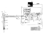
以下、実施の形態に基いて本発明を説明する。図1に示すように本発明に係る内視鏡装置は、被写体の撮像画像を出力する内視鏡1と画像処理及び制御用のプロセッサ2とを組合せている。
【0015】
前記内視鏡1の先端部には体腔内に挿入可能な細長の挿入部1aが設けられており、その挿入部1aにはズーム機能付き光学レンズ系3が組込まれている。
【0016】
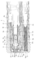
図2は、内視鏡先端部の概略を示したものであり、ズーム機能付き光学レンズ系3は、固定位置に設けた不動レンズ系3aと、前記不動レンズ系3aに対して相対移動可能な可動レンズ系3bと、前記不動レンズ系3a及び前記可動レンズ系3bを通した光信号を電気信号に変換し、かつ前記不動レンズ系3a及び前記可動レンズ系3bに対して相対移動可能な撮像素子3cとを含んでいる。撮像素子3cとしてはCCD素子(以下、CCD素子3cと表記する)を用いている。
【0017】
またプロセッサ2は自動焦点調整部15と定焦点調整部16とを有しており、定焦点調整部16は、不動レンズ系3aと可動レンズ系3bとの位置関係を、光学レンズ系3の短焦点距離内で調整し、かつCCD素子3cを光学レンズ系3の短焦点距離位置に位置調整する。一方、自動焦点調整部15は、不動レンズ系3aと可動レンズ系3bとの位置関係を光学レンズ系3の長焦点距離端と短焦点距離端の範囲内で調整し、かつCCD素子3cを光学レンズ系3の長焦点距離端と短焦点距離端の範囲内で位置調整する。
ズーム機能を備えた光学レンズ系3の一例を図2及び図3に基いて説明する。図2及び図3に示すように、内視鏡1の挿入部1aには筒状をなす不動レンズ枠3dが設置され、不動レンズ枠3dに光学レンズ系3の不動レンズ3aを搭載して不動レンズ3aを挿入部1aの先端側に固定して設ける。また不動レンズ枠3dの内側に筒状をなすガイド枠3eを設け、ガイド枠3eには光軸方向(図3の左右方向)に沿って直線案内溝3f、3gを設けている。
【0018】
ガイド枠3eの内側には可動レンズ枠3hが光軸方向に移動可動に嵌め込まれており、可動レンズ枠3hのキー3iとガイド枠3eの上段の直線案内溝3fとの嵌め合せにより可動レンズ枠3hを光軸の周りに回転させることなく光軸方向に直線移動させる。またガイド枠3eの外側にはリング3jが嵌め込まれており、リング3jと可動レンズ枠3hとはガイド枠3eの下段の直線案内溝3gを貫通したネジ3kで締結されている。なお、ガイド枠3eの内側に位置する枠3lには光軸方向へのネジ3kの動きを許容する図示しないスリットが設けられている。
【0019】
またリング3jの鍔部3mには連結部材4aを介して図1のソレノイド(またはモータ)4が連動されており、ソレノイド4により可動レンズ枠3hを光軸方向に直線移動させる。可動レンズ枠3hには可動レンズ系3bが不動レンズ系3aに対峙して搭載され、可動レンズ枠3hが直線移動することにより不動レンズ系3aと可動レンズ系3bとの相対距離が可変する。またリング3jとバネ座3nとの間にはスプリング3oが設けられ、スプリング3oはソレノイド4による可動レンズ枠3hへの力が解除された際に可動レンズ枠3hを不動レンズ系3a側に押し戻して可動レンズ系3bを所定の位置に復帰させるように作用する。リング3oによる可動レンズ系3bの復帰位置は、長焦点距離の範囲に設定される(図6(a))。
【0020】
またガイド枠3eの内側には撮像素子枠3pが光軸方向に移動可動に嵌め込まれており、撮像素子枠3pのキー3qとガイド枠3eの上段の直線案内溝3fとの嵌め合せにより撮像素子枠3pは光軸の周りに回転させることなく、かつカム機構18により光軸方向に直線移動されている。19はシール材である。また撮像素子枠3pには撮像素子3cとしてのCCD素子(以下、CCD素子3cと表記する)が可動レンズ系3aに対峙させて搭載されている。また撮像素子枠3pと可動レンズ枠3hとの間にはスプリング3rが設けられ、スプリング3rは可動レンズ系3bに後述のCCD素子3cの受光面が接触するのを防止する。なお、図3のスプリング3rに変えて、図2に示すように可動レンズ系3bとCCD素子3cとの間にカバーガラス3vを配置し、撮像素子3cの受光面を保護するようにしてもよい。またカム機構18は、撮像素子枠3pを可動レンズ系3bに対して光軸方向に移動させるように動作する。
【0021】
また撮像素子枠3pには、CCD素子3cを駆動制御して光学レンズ系3を通した光信号を電気信号に変換して出力させるCCD駆動回路3s等の回路と、CCD素子3cからの電気信号を伝送する信号ケーブル3t等が搭載される。信号ケーブル3tはCCD素子3cからの電気的な映像信号を後述の初段映像信号処理回路6に伝送し、かつ初段映像信号処理回路6で信号処理された信号をCCD駆動回路3s等に伝送する双方向性のものであり、後述するタイミングコントロール10による時間制御の下に双方向性の信号伝送が制御される。
【0022】
また挿入部1aには送光光路5が光学レンズ系3に隣接して設置されている。この送光光路5は後述する調光部9からの調光された光を挿入部1aに導入するものとして作用し、送光光路5は挿入部1aの先端端面から送光レンズ5aを通して被写体に平行光線による光照射を行う。なお、挿入部1aは体腔内に挿入するものであるから細径である必要があり、送光光路5は光ファイバーを束ねた光ファイバー束として構成することが望ましい。
【0023】
一方、図1に示すように前記プロセッサ2には、初段映像信号処理回路6と、画像メモリ7と、後段映像信号処理回路8と、調光部9と、タイミングコントロール10と、システムコントーロール11と、フロントパネルスイッチ12と、電源部13とが搭載されている。
【0024】
初段映像信号処理回路6は、信号ケーブル3tを通して伝送されるCCD素子3cからの電気信号を信号処理し、その映像信号を画像メモリ7に逐次記憶させる。また後段映像信号処理回路8は、画像メモリ7に蓄積された映像信号を逐次読み出して信号処理を行い、その映像信号をモニタ―14に出力する。モニタ―14は後段映像信号処理回路8から出力される映像信号を表示面に可視画像として表示する。
【0025】
またシステムコントーロール11はキーボード11aから入力される指令データ及び図示しないメモリに記憶されたプログラムに基いてプロセッサ2の全体的な動作を制御し、タイミングコントロール10はシステムコントーロール11からの指令に基いてプロセッサ2の動作タイミングを制御する。またプロセッサ2は電源部13から電力供給を受ける。
【0026】
また調光部9は、信号ケーブル3tを通して伝送されるCCD素子3cからの電気信号に基いて撮像画像の明るさを検出して調光制御信号を得て、その調光制御信号に基いて絞りの開閉度合を制御し、その開閉度が制御された絞りに光源からの光を通過させ、光量が調整された光を送光光路5に出力する。
【0027】
さらに実施形態の内視鏡装置は、図1に示すように被写体までの距離に応じてズーム機能付き光学レンズ系3の焦点位置を調整する自動焦点調整部15と、前記光学レンズ系3の焦点位置を予め定められた固定の焦点位置に合焦する定焦点調整部16と、前記自動焦点調整部15と前記定焦点調整部16との動作を切替える切替スイッチ17とを有している。
【0028】
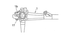
またこの切替スイッチ17は図1,図4及び図5に示すように内視鏡1の操作部1bに組込むことが望ましい。図5に示すように切替スイッチ17は図示しない電気接点と、この電気接点をON/OFFさせる操作ノブ17aとを有している。操作ノブ17aは回転軸に嵌め込まれる環状軸部17bと環状軸部17bから半径方向に突き出た突起部17cとを有している。突起部17cには切替スイッチ17の操作状態を示す「W」、「T」の識別文字が付されている。切替スイッチ17の操作ノブ17aを「W」方向に回転させると、定焦点調整部16を動作させることとなり、「T」方向に回転させると、定焦点調整部16を停止させて自動焦点調整部15に切替えて動作させることとなる。切替スイッチ17は内視鏡1の操作部1bに組込むようにしたが、内視鏡1の操作部1b以外に組込んでもよい。なお、切替スイッチ17は光学レンズ3のズーム機能を起動させ、また光学レンズ3のズーム機能を停止させるものであるから、以下の説明では切替スイッチ17をズームレバー17として表記する。
【0029】
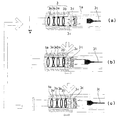
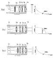
次にズーム機能付き光学レンズ系3の焦点調整を行う自動焦点調整部15及び定焦点調整部16について図1,図6及び図7に基いて説明する。図6(a)は、ズームレバー17をOFF(ズームレバー17の操作ノブ17aを「W」側に回転する)にして、定焦点調整部16により、光学レンズ系3の焦点距離を短焦点距離側の特定の焦点距離にシフトさせて焦点合せを行い、内視鏡1による撮像を行う場合を示す図である。図6(b)は、ズームレバー17をON(ズームレバー17の操作ノブ17aを「T」側に回転する)にして定焦点調整部16を停止させて自動焦点調整部15を起動させ、光学レンズ系3の焦点距離を長焦点距離端と短焦点距離端の範囲内で変化させて焦点合わせを行う状態に移行する場合を示す図である。また図6(b)には、図6(a)と比較して明らかなように図6(a)に示したCCD素子3cが可動レンズ系3b側に前進して光学レンズ系3の焦点距離を長焦点距離端と短焦点距離端の範囲内で変化させて焦点合わせを行う様子を示している。図6(c)は、ズームレバー17をON(ズームレバー17の操作ノブ17aを「T」側に回転する)にして定焦点調整部16を停止させて自動焦点調整部15を起動させ、光学レンズ系3の焦点距離を長焦点距離端と短焦点距離端の範囲内で変化させて焦点合わせが行われる状態を示す図である。なお、図6には動作を説明するのに必要最小限の符号のみを付してある。また白抜きの矢印は動作順を示している。
【0030】
前記自動焦点調整部15は、図1及び図6(c)に示すように光学レンズ系3の焦点距離を長焦点距離端と短焦点距離端の範囲内で変化させて焦点合わせを行うものであり、図1のソレノイド4を駆動制御するソレノイド駆動回路部と合焦検知回路部とが含まれている。自動焦点調整部15は、図6(b)に示すようにズームレバー17から入力するON信号に基いてカム機構18により撮像素子枠3pを可動レンズ系3b側に前進させ、CCD素子3cを可動レンズ系3bに近づける。
【0031】
さらに自動焦点調整部15の前記合焦検知回路部は初段信号処理回路6から出力される映像信号に基いて直接フォーカシング情報を検出し光学レンズ系3による被写体撮像画像のピントがぼけていた場合(図6(b))にはCCD素子3cに対する光学レンズ系3の焦点距離を調整する焦点調整信号を得る。前記ソレノイド駆動回路部は前記合焦検知回路部からの焦点調整信号に基いてソレノイド4を駆動して光学レンズ系3の可動レンズ系3bを光軸方向に可動させて焦点調節を行う(図6(c))。
【0032】
前記定焦点調整部16は、図1及び図6(a)に示すようにズームレバー17のOFF信号を受けてカム機構18により撮像素子枠3pを可動レンズ系3bに対して光軸方向に後退させ、光学レンズ系3の焦点距離を短焦点距離側の特定の焦点距離にシフトさせて焦点合せを行う(図6(a))。
【0033】
さらに前記自動焦点調整部15及び前記定焦点調整部16は、図7に示すように撮像素子としてのCCD素子3cが出力する信号の所定周波数成分を評価値Sとして焦点位置の調整を行うものであり、自動焦点調整部15及び定焦点調整部16は、光学レンズ系3の合焦度合に応じてCCD素子3cが出力する信号の高周波成分が増減することを利用して、前記高周波成分を評価値Sとして焦点位置の調整を行う。撮像素子3cとしてCCD素子(以下、CCD素子3cと表記する)を用いた場合の自動焦点調整部15と定焦点調整部16を図6及び図7に基いて説明する。なお図7(b)は自動焦点調整部15と定焦点調整部16との動作説明に用いる。
【0034】
図6と図7とを対応させると、図6(a)及び(c)の場合におけるCCD素子3cの出力信号に含まれる高周波成分は図7(b)に示すように増加し、図6(b)の場合におけるCCD素子3cの出力信号に含まれる高周波成分は図7(a)又は(c)に示すように減少する。
図6(b)に示すように自動焦点調整部15によりCCD素子3cが可動レンズ系3b側に近づけられて光学レンズ系3の焦点位置がCCD素子3cより遠い位置にあると、図7(a)に示すようにCCD素子3cから出力される信号の高周波成分は減少し、自動焦点調整部15により光学レンズ系3の焦点がCCD素子3cの受光面上に合焦されると、図7(b)に示すようにCCD素子3cから出力される信号の高周波成分は増加する。
【0035】
自動焦点調整部15は、光学レンズ系3の合焦度合に応じてCCD素子3cが出力する信号の高周波成分が増減することを利用し、図7(a)に示すようにCCD素子3cから出力される信号の高周波成分が減少する場合には可動レンズ系3bがCCD素子3c側に近づけられて光学レンズ系3の焦点位置がCCD素子3cより遠い位置にあると判断して、ソレノイド4で可動レンズ系3bを光軸方向に移動させる動作とカム機構18でCCD素子3cを光軸方向に移動させる動作とを並行して行うことにより光学レンズ系3の焦点合せを続行し、図7(b)に示すようにCCD素子3cから出力される信号の高周波成分は増加し、評価値Sが最大となると、光学レンズ系3の焦点がCCD素子3cの受光面上に合焦されたと判断して光学レンズ系3の焦点合せを終了させる。
【0036】
一方、図6(a)において定焦点調整部16によりCCD素子3cが可動レンズ系3bから光軸方向に遠ざけられて光学レンズ系3の焦点位置がCCD素子3cより手前側にあると、図7(c)に示すようにCCD素子3cから出力される信号の高周波成分は減少し、定焦点調整部16により光学レンズ系3の焦点がCCD素子3cの受光面上に合焦されると、図7(b)に示すようにCCD素子3cから出力される信号の高周波成分は増加する。
【0037】
定焦点調整部16は、光学レンズ系3の合焦度合に応じてCCD素子3cが出力する信号の高周波成分が増減することを利用し、図7(c)に示すようにCCD素子3cから出力される信号の高周波成分が減少する場合にはCCD素子3cが可動レンズ系3bから遠ざけられて光学レンズ系3の焦点位置がCCD素子3cの手前側の位置にあると判断して、ソレノイド4で可動レンズ系3bをCCD素子3b側の光軸方向に移動させて光学レンズ系3の焦点合せを続行し、図7(b)に示すようにCCD素子3cから出力される信号の高周波成分は増加して評価値Sが最大となると、光学レンズ系3の焦点がCCD素子3cの受光面上に合焦されたと判断して光学レンズ系3の焦点合せを終了させる。
【0038】
次に本発明の内視鏡装置を用いて消化器官の観察を行う場合を図8により説明する。まず図8において、ズームレバー17がONされているかいないかがシステムコントーロール11により検出される(ステップS1)。
【0039】
システムコントーロール11はズームレバー17がOFFされていることを検出すると、定焦点調整部16を起動させ、消化器官の観察対象となる全域を内視鏡装置により観察する通常観察モードに切替える(ステップS2)。
【0040】
定焦点調整部16は起動すると、ソレノイド4を停止させてソレノイド4がスプリング3oに抗して可動レンズ枠3hに付与している力を解除する。これに伴って可動レンズ系3bはスプリング3oのバネ力を受けて不動レンズ系3b側に近づき、不動レンズ系3aと可動レンズ系3bの配置関係は、光学レンズ系3の焦点距離を短焦点距離側の特定の焦点距離にシフトさせて焦点合せを行う位置関係となる(図6(a))。
【0041】
また定焦点調整部16はカム機構18によるCCD素子3cの可動レンズ系3aに対する位置関係を、光学レンズ系3の焦点距離を短焦点距離側の特定の焦点距離にシフトさせて焦点合せを行うように調整設定する。
【0042】
次いで定焦点調整部16はCCD素子3cの出力信号に含まれる高周波成分を監視する。この場合、CCD素子3cの信号に含まれる高周波成分は図7(a)に示すように減少するため、定焦点調整部16は光学レンズ系3の焦点合せが終了していないことを検出し、ソレノイド4により可動レンズ系3bを不動レンズ系3aに対して光軸方向に移動させて、光学レンズ系3の焦点位置にCCD素子3cの受光面上になるように焦点調整を継続する。定焦点調整部16は図7(b)に示すようにCCD素子3cから出力される信号の高周波成分が増加して評価値Sが最大となった場合に光学レンズ系3の焦点がCCD素子3cの受光面上に合焦されたと判断して光学レンズ系3の焦点合せを終了させる(ステップS3)。この場合、光学レンズ系3の焦点位置は短焦点距離側の特定の焦点位置にあるため、消化器官の観察対象となる全域を視野内に収めることとなり、CCD素子3cからの撮像信号は映像信号処理回路6,8で信号処理され、モニタ―14に可視画像として表示される。
【0043】
この状態で消化器官の観察対象となる全域を内視鏡装置により観察する通常観察モードでの観察が行われる(ステップS4)。
【0044】
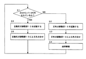
通常観察モードでの観察が終了してズームレバー17を「T」側に切替えると、システムコントーロール11はズームレバー17がONされたことを検出し、自動焦点調整部15を起動させ、消化器官の微細病変を拡大して内視鏡装置により観察する拡大観察モードに切替える(ステップS5)。
【0045】
自動焦点調整部15は起動すると、ズームレバー17のON信号に基いてカム機構18により撮像素子枠3pを可動レンズ系3b側に前進させる(図6(b))。この場合、光学レンズ系3特に不動レンズ系3a及び可動レンズ系3bとCCD素子3cとの配置関係は、光学レンズ系3の焦点距離が長焦点距離端と短焦点距離端の範囲内の位置関係となる(図6(b))。
【0046】
自動焦点調整部15は、CCD素子3cの出力信号に含まれる高周波成分を監視する。自動焦点調整部15は、図7(a)に示すようにCCD素子3cから出力される信号の高周波成分が減少する場合には可動レンズ系3bがCCD素子3c側に近づけられて光学レンズ系3の焦点位置がCCD素子3cより遠い位置にあると判断して、ソレノイド4で可動レンズ系3bを光軸方向に移動させる動作とカム機構18でCCD素子3cを光軸方向に移動させる動作とを並行して行うことにより光学レンズ系3の焦点合せを続行し、図7(b)に示すようにCCD素子3cから出力される信号の高周波成分は増加して評価値Sが最大になると、光学レンズ系3の焦点がCCD素子3cの受光面上に合焦されたと判断して光学レンズ系3の焦点合せを終了させる(ステップS6)。この場合、光学レンズ系3の焦点距離が長焦点距離端と短焦点距離端の範囲内となるため(図6(b))、消化器官の微細な病変部分を視野内に収めることとなり、CCD素子3cからの撮像信号は映像信号処理回路6,8で信号処理され、モニタ―14に可視画像として拡大表示される。
【0047】
以上の実施の形態による説明では、医療現場で用いる内視鏡装置を例にとって説明したが、本発明の内視鏡装置は工業用の分野に用いられる内視鏡装置にも同様に適用することができるものであり、医療用分野のものに限定されるものではない。
【0048】
【発明の効果】
以上説明したように本発明によれば、自動焦点調整部による光学レンズ系の焦点位置の調整動作を必要に応じて停止させ、光学レンズ系の焦点位置を予め定められた固定焦点位置に合焦するため、内視鏡の先端部から処置具を突出して処置を行う場合にも、この処置具に自動焦点調整部による焦点合せが行われることはなく、処置具の動きに関係なく短焦点距離範囲内の固定焦点位置での通常観察と、長焦点距離範囲内での焦点合せによる拡大観察とを切替えることができ、処置具等の使用時の操作性を向上させることができるばかりでなく、内視鏡を体腔内に挿入する時間が従来と比較して短くすることができ、患者に与える苦痛を軽減することができる。
【図面の簡単な説明】
【図1】本発明に係る内視鏡装置の一例を示す構成図である。
【図2】内視鏡先端部を示す断面図である。
【図3】CCD素子と光学レンズ系との関係を示す断面図である。
【図4】内視鏡の操作部を示す図である。
【図5】切替スイッチを分解して示す図である。
【図6】光学レンズ系の動作を示す図である。
【図7】光学レンズ系とCCD素子から出力される信号の状態を示す図である。
【図8】動作を示すフローチャートである。
【符号の説明】
1 内視鏡
2 プロセッサ
3 光学レンズ系
3a 不動レンズ系
3b 可動レンズ系
4 ソレノイド
15 自動焦点調整部
16 定焦点調整部
17 切替スイッチ(ズームレバー)
18 カム機構[0001]
【Technical field】
The present invention relates to an endoscope apparatus that improves the operability of an endoscope used in fields such as medicine and industry.
[0002]
[Prior art and its problems]
Endoscopic devices adopted for diagnosis of digestive organs are configured to observe the entire tissue of the digestive organs by changing the focal length to a short focal length, but when changing to this long focal length In this case, if the distance from the subject is increased, the image becomes smaller, and it becomes impossible to observe a minute lesion in detail. For this reason, the focal length is changed to a short focal length, and a fine lesion is enlarged and observed in detail.
[0003]
However, in the observation in which the focal length is changed to the short focal length, the enlargement ratio is about 10 times at most, and the magnification is insufficient for observing minute lesions in detail. Therefore, an optical lens provided with a zoom mechanism is used. In order to activate this zoom mechanism, it is necessary to attach a zoom lever for activating the zoom mechanism to the operation unit of the endoscope. By operating the zoom lever, the focal length can be changed.
[0004]
On the other hand, if the subject is enlarged and observed with the focal length changed to a long focal length, the focal position may shift (out of focus). In this case, it is necessary to adjust the focus at the long focal length position. There is. Therefore, a doctor or an operator who handles the endoscope apparatus needs to operate the treatment tool loaded on the endoscope, the zoom lever, and the telephoto lens, respectively, which are difficult to perform. Therefore, an endoscope apparatus has been developed that uses an optical lens system having a zoom function and includes a focal length varying means that adjusts the focal position of the optical lens system with a zoom function according to the distance to the subject ( JP-A-4-13112).
[0005]
The endoscope apparatus disclosed in Japanese Patent Laid-Open No. 4-13112 uses a focal length varying means that can vary the focal length according to the distance from the subject. The focal length changing unit normally observes the subject by changing the focal length to a long focal length when the subject is at a long distance and changing the focal length to a short focal length when the subject is at a short distance. Alternatively, the subject is magnified and observed, and the focal length varying means is driven as needed.
[0006]
By the way, when a treatment tool is loaded on an endoscope to perform a treatment, the treatment tool is used in a state where the treatment tool protrudes forward from the distal end side of the endoscope and light is irradiated to a treatment portion by the treatment tool. In addition, since the focal length is adjusted according to the distance to the subject in an environment where light reflection occurs in the treatment tool, the focal length varying means does not focus on the subject but the endoscope If the treatment tool is at a long distance, the focal length is changed to a long focal length, and if the treatment tool is at a close distance, the focal length is changed to a short focal length. .
[0007]
Accordingly, the focal length varying means operates every time the treatment instrument is moved, and it is difficult to perform treatment with the treatment instrument. Further, since it takes time to focus by the focal length changing means every time the treatment tool is moved, the time for inserting the endoscope into the body cavity becomes long, and the patient is painful by that much.
[0008]
OBJECT OF THE INVENTION
The present invention relates to an endoscope apparatus in which an operation of adjusting a focal position of an optical lens system by an automatic focus adjustment unit is stopped as necessary to improve operability when using a treatment instrument or the like.
[0009]
Summary of the Invention
In order to achieve the above object, an endoscope apparatus according to the present invention is an endoscope apparatus that observes a subject with an optical lens system having a zoom function, according to the distance to the subject. The focusing operation is performed while changing the focal length of the optical lens system. An automatic focus adjustment unit, and the optical lens system Focal length The predetermined Perform focusing operation after shifting to a specific focal length It has a fixed focus adjustment part, and the changeover switch which switches operation | movement with the said automatic focus adjustment part and the said fixed focus adjustment part, It is characterized by the above-mentioned. Further, it is desirable that the changeover switch is incorporated in the operation unit of the endoscope.
[0010]
In addition, the fixed focal point adjustment unit moves the focal length of the optical lens system to the short focal length side in the variable focal length range by the automatic focal point adjustment unit. shift .
[0011]
In addition, the image pickup device converts an optical signal that has passed through the optical lens system into an electrical signal, and the automatic focus adjustment unit and the fixed focus adjustment unit use a predetermined frequency component of a signal output from the image pickup device as an evaluation value When the image pickup device is a charge coupled device (CCD device), the automatic focus adjustment unit and the fixed focus adjustment unit are configured to determine a focus point position according to the focus degree of the optical lens system. Using the fact that the high frequency component of the signal output from the charge coupled device (CCD device) increases or decreases, the focus position is determined using the high frequency component as an evaluation value.
[0012]
The optical lens system includes an immovable lens system provided at a fixed position, a movable lens system movable relative to the immobile lens system, and an optical signal that passes through the immobile lens system and the movable lens system. And an image sensor that can move relative to the stationary lens system and the movable lens system.
[0013]
Further, when using the optical lens system, the fixed focus adjustment unit, the positional relationship between the stationary lens system and the movable lens system, Above It adjusts within the short focal length of the optical lens system, and adjusts the position of the charge coupled device (CCD element) at the short focal length position of the optical lens system, while the automatic focus adjusting unit is the fixed lens. The positional relationship between the system and the movable lens system Above Optical lens system Within the range of the long focal length end and short focal length end And the imaging device (Charge coupled device) The Above Optical lens system Within the range of the long focal length end and short focal length end The position is adjusted.
[0014]
DETAILED DESCRIPTION OF THE INVENTION
Hereinafter, the present invention will be described based on embodiments. As shown in FIG. 1, an endoscope apparatus according to the present invention combines an
[0015]
An
[0016]
FIG. 2 shows an outline of the distal end portion of the endoscope. The
[0017]
The
An example of the
[0018]
A
[0019]
Further, the solenoid 3 (or motor) 4 of FIG. 1 is linked to the
[0020]
An
[0021]
The
[0022]
A light transmission
[0023]
On the other hand, as shown in FIG. 1, the
[0024]
The first-stage video
[0025]
The
[0026]
The
[0027]
Furthermore, as shown in FIG. 1, the endoscope apparatus according to the embodiment includes an automatic
[0028]
The
[0029]
Next, the automatic
[0030]
As shown in FIGS. 1 and 6C, the automatic
[0031]
Further, when the focus detection circuit unit of the automatic
[0032]
As shown in FIGS. 1 and 6A, the fixed
[0033]
Further, the automatic
[0034]
If FIG. 6 and FIG. 7 are made to correspond, the high frequency component contained in the output signal of
As shown in FIG. 6B, when the
[0035]
The automatic
[0036]
On the other hand, in FIG. 6A, when the
[0037]
The fixed
[0038]
Next, a case where the digestive organ is observed using the endoscope apparatus of the present invention will be described with reference to FIG. First, in FIG. 8, whether or not the
[0039]
When the
[0040]
When the fixed
[0041]
The fixed focal
[0042]
Next, the fixed
[0043]
In this state, observation is performed in the normal observation mode in which the entire region to be observed of the digestive organs is observed by the endoscope apparatus (step S4).
[0044]
When the observation in the normal observation mode is finished and the
[0045]
When the automatic
[0046]
The automatic
[0047]
In the above description of the embodiment, the endoscope apparatus used in the medical field has been described as an example. However, the endoscope apparatus of the present invention is similarly applied to an endoscope apparatus used in an industrial field. However, the present invention is not limited to the medical field.
[0048]
【The invention's effect】
As described above, according to the present invention, the adjustment operation of the focal position of the optical lens system by the automatic focus adjustment unit is stopped as necessary, and the focal position of the optical lens system is focused on a predetermined fixed focal position. Therefore, even when the treatment tool is protruded from the distal end portion of the endoscope, the treatment tool is not focused by the automatic focus adjustment unit, and the short focal length is not affected by the movement of the treatment tool. It is possible to switch between normal observation at a fixed focal position within the range and magnified observation by focusing within the long focal length range, and not only can improve operability when using a treatment instrument, The time for inserting the endoscope into the body cavity can be shortened compared to the conventional case, and the pain given to the patient can be reduced.
[Brief description of the drawings]
FIG. 1 is a configuration diagram showing an example of an endoscope apparatus according to the present invention.
FIG. 2 is a cross-sectional view showing a distal end portion of an endoscope.
FIG. 3 is a cross-sectional view showing a relationship between a CCD element and an optical lens system.
FIG. 4 is a diagram illustrating an operation unit of an endoscope.
FIG. 5 is an exploded view of the changeover switch.
FIG. 6 is a diagram illustrating the operation of the optical lens system.
FIG. 7 is a diagram illustrating a state of signals output from an optical lens system and a CCD element.
FIG. 8 is a flowchart showing an operation.
[Explanation of symbols]
1 Endoscope
2 processor
3 Optical lens system
3a fixed lens system
3b Movable lens system
4 Solenoid
15 Automatic focus adjustment unit
16 Fixed focus adjustment unit
17 Changeover switch (zoom lever)
18 Cam mechanism
Claims (9)
被写体までの距離に応じて前記光学レンズ系の焦点距離を変化させながら、合焦動作を行う自動焦点調整部と、
前記光学レンズ系の焦点距離を予め定められた特定の焦点距離にシフトさせた上で合焦動作を行う定焦点調整部と、
前記自動焦点調整部と前記定焦点調整部との動作を切替える切替スイッチとを有することを特徴とする内視鏡装置。In an endoscope apparatus for observing a subject with an optical lens system having a zoom function,
An automatic focus adjustment unit that performs a focusing operation while changing the focal length of the optical lens system according to the distance to the subject;
A constant focus adjustment unit that performs a focusing operation on the shifted into a specific focal length and the focal length predetermined for the optical lens system,
An endoscope apparatus comprising: a changeover switch that switches operations between the automatic focus adjustment unit and the fixed focus adjustment unit.
前記切替スイッチは内視鏡の操作部に組込まれたことを特徴とする内視鏡装置。The endoscope apparatus according to claim 1, wherein
An endoscope apparatus, wherein the changeover switch is incorporated in an operation unit of an endoscope.
前記定焦点調整部は、前記光学レンズ系の焦点距離を、前記自動焦点調節部による可変焦点距離距離範囲のうちの短焦点距離側にシフトするものであることを特徴とする内視鏡装置。The endoscope apparatus according to claim 1, wherein
The endoscope apparatus, wherein the fixed focal point adjustment unit shifts a focal length of the optical lens system to a short focal length side in a variable focal length range by the automatic focal point adjustment unit.
前記光学レンズ系を通した光信号を電気信号に変換する撮像素子を有し、
前記自動焦点調整部及び前記定焦点調整部は、前記撮像素子が出力する信号の所定周波数成分を評価値として焦点位置の調整を行うことを特徴とする内視鏡装置。The endoscope apparatus according to claim 1, wherein
An image sensor that converts an optical signal that has passed through the optical lens system into an electrical signal;
The endoscope apparatus, wherein the automatic focus adjustment unit and the fixed focus adjustment unit adjust a focal position using a predetermined frequency component of a signal output from the imaging device as an evaluation value.
前記撮像素子は、電荷結合素子(CCD素子)であることを特徴とする内視鏡装置。The endoscope apparatus according to claim 4, wherein
An endoscope apparatus, wherein the image pickup device is a charge coupled device (CCD device).
前記自動焦点調整部及び前記定焦点調整部は、前記光学レンズ系の合焦度合に応じて前記電荷結合素子(CCD素子)が出力する信号の高周波成分が増減することを利用して、前記高周波成分を評価値として焦点位置の調整を行うことを特徴とする内視鏡装置。The endoscope apparatus according to claim 5, wherein
The automatic focus adjustment unit and the fixed focus adjustment unit utilize the fact that a high frequency component of a signal output from the charge coupled device (CCD device) increases or decreases in accordance with a degree of focusing of the optical lens system. An endoscope apparatus characterized by adjusting a focal position using a component as an evaluation value.
前記光学レンズ系は、固定位置に設けた不動レンズ系と、前記不動レンズ系に対して相対移動可能な可動レンズ系と、前記不動レンズ系及び前記可動レンズ系を通した光信号を電気信号に変換し、かつ前記不動レンズ系及び前記可動レンズ系に対して相対移動可能な撮像素子とを含むことを特徴とする内視鏡装置。The endoscope apparatus according to claim 1, wherein
The optical lens system includes an immovable lens system provided at a fixed position, a movable lens system movable relative to the immobile lens system, and an optical signal that passes through the immovable lens system and the movable lens system as an electrical signal. An endoscope apparatus comprising: an imaging device that converts and is movable relative to the stationary lens system and the movable lens system.
前記定焦点調整部は、前記不動レンズ系と前記可動レンズ系との位置関係を、前記光学レンズ系の短焦点距離内で調整し、かつ前記撮像素子を前記光学レンズ系の短焦点距離位置に位置調整することを特徴とする内視鏡装置。The endoscope apparatus according to claim 7, wherein
The constant focus adjustment unit, the positional relationship between the stationary lens system and the movable lens system is adjusted in a short focal length of the optical lens system, and the imaging element in the short focal length position of the optical lens system An endoscope apparatus characterized by adjusting the position.
前記自動焦点調整部は、前記不動レンズ系と前記可動レンズ系との位置関係を前記光学レンズ系の長焦点距離端と短焦点距離端の範囲内で調整し、かつ前記撮像素子を前記光学レンズ系の長焦点距離端と短焦点距離端の範囲内で位置調整することを特徴とする内視鏡装置。The endoscope apparatus according to claim 7, wherein
The automatic focus adjusting portion adjusts the positional relationship between the movable lens system immovable lens system within the scope of the long focal length end and the short focal length end of the optical lens system, and the imaging element and said optical lens An endoscope apparatus , wherein the position is adjusted within a range of a long focal length end and a short focal length end of the system.
Priority Applications (1)
| Application Number | Priority Date | Filing Date | Title |
|---|---|---|---|
| JP2001058133A JP4338331B2 (en) | 2001-03-02 | 2001-03-02 | Endoscope device |
Applications Claiming Priority (1)
| Application Number | Priority Date | Filing Date | Title |
|---|---|---|---|
| JP2001058133A JP4338331B2 (en) | 2001-03-02 | 2001-03-02 | Endoscope device |
Publications (2)
| Publication Number | Publication Date |
|---|---|
| JP2002258164A JP2002258164A (en) | 2002-09-11 |
| JP4338331B2 true JP4338331B2 (en) | 2009-10-07 |
Family
ID=18917904
Family Applications (1)
| Application Number | Title | Priority Date | Filing Date |
|---|---|---|---|
| JP2001058133A Expired - Fee Related JP4338331B2 (en) | 2001-03-02 | 2001-03-02 | Endoscope device |
Country Status (1)
| Country | Link |
|---|---|
| JP (1) | JP4338331B2 (en) |
Families Citing this family (5)
| Publication number | Priority date | Publication date | Assignee | Title |
|---|---|---|---|---|
| JP4448277B2 (en) * | 2002-10-18 | 2010-04-07 | Hoya株式会社 | Endoscope autofocus method |
| JP5948076B2 (en) | 2011-08-23 | 2016-07-06 | オリンパス株式会社 | Focus control device, endoscope device and focus control method |
| JP5953187B2 (en) | 2011-10-11 | 2016-07-20 | オリンパス株式会社 | Focus control device, endoscope system, and focus control method |
| JP5973708B2 (en) | 2011-10-21 | 2016-08-23 | オリンパス株式会社 | Imaging apparatus and endoscope apparatus |
| JP5953049B2 (en) * | 2012-01-24 | 2016-07-13 | オリンパス株式会社 | Endoscope system |
-
2001
- 2001-03-02 JP JP2001058133A patent/JP4338331B2/en not_active Expired - Fee Related
Also Published As
| Publication number | Publication date |
|---|---|
| JP2002258164A (en) | 2002-09-11 |
Similar Documents
| Publication | Publication Date | Title |
|---|---|---|
| JP3831318B2 (en) | Endoscopic imaging device | |
| CA2178240C (en) | Video scope camera | |
| US7852371B2 (en) | Autoclavable video camera for an endoscope | |
| US5662584A (en) | Endoscope with position display for zoom lens unit and imaging device | |
| WO2010116902A1 (en) | Endoscopic device | |
| EP1088510A1 (en) | Endoscope with objective lens drive mechanism | |
| JP3980284B2 (en) | Endoscope device | |
| JP3594254B2 (en) | Endoscope device | |
| JP4179798B2 (en) | Endoscopic surgery device | |
| JP3255448B2 (en) | Endoscope device | |
| USRE37356E1 (en) | Endoscope with position display for zoom lens unit and imaging device | |
| JP4338331B2 (en) | Endoscope device | |
| JPH10127563A (en) | Endoscope unit | |
| JP3645055B2 (en) | Video scope | |
| JP4354044B2 (en) | Endoscope observation system | |
| JP2000166860A (en) | Endoscope | |
| JP3756590B2 (en) | Endoscope device | |
| JP3955458B2 (en) | Endoscope autofocus device | |
| JP2004159924A (en) | Endoscope | |
| JP2002350735A (en) | Microscope for surgery | |
| JPH08131455A (en) | Microscope for operation | |
| JP3431580B2 (en) | Endoscope device | |
| US20210258456A1 (en) | Interchangeable lens, imaging apparatus, and rotation detection apparatus | |
| JP2004065316A (en) | Endoscope instrument | |
| JP4115967B2 (en) | Surgical microscope |
Legal Events
| Date | Code | Title | Description |
|---|---|---|---|
| A621 | Written request for application examination |
Free format text: JAPANESE INTERMEDIATE CODE: A621 Effective date: 20050207 |
|
| A131 | Notification of reasons for refusal |
Free format text: JAPANESE INTERMEDIATE CODE: A131 Effective date: 20080219 |
|
| A521 | Request for written amendment filed |
Free format text: JAPANESE INTERMEDIATE CODE: A523 Effective date: 20080418 |
|
| A711 | Notification of change in applicant |
Free format text: JAPANESE INTERMEDIATE CODE: A712 Effective date: 20080430 |
|
| TRDD | Decision of grant or rejection written | ||
| A01 | Written decision to grant a patent or to grant a registration (utility model) |
Free format text: JAPANESE INTERMEDIATE CODE: A01 Effective date: 20090602 |
|
| A01 | Written decision to grant a patent or to grant a registration (utility model) |
Free format text: JAPANESE INTERMEDIATE CODE: A01 |
|
| A61 | First payment of annual fees (during grant procedure) |
Free format text: JAPANESE INTERMEDIATE CODE: A61 Effective date: 20090630 |
|
| R150 | Certificate of patent or registration of utility model |
Ref document number: 4338331 Country of ref document: JP Free format text: JAPANESE INTERMEDIATE CODE: R150 Free format text: JAPANESE INTERMEDIATE CODE: R150 |
|
| FPAY | Renewal fee payment (event date is renewal date of database) |
Free format text: PAYMENT UNTIL: 20120710 Year of fee payment: 3 |
|
| FPAY | Renewal fee payment (event date is renewal date of database) |
Free format text: PAYMENT UNTIL: 20120710 Year of fee payment: 3 |
|
| FPAY | Renewal fee payment (event date is renewal date of database) |
Free format text: PAYMENT UNTIL: 20130710 Year of fee payment: 4 |
|
| R250 | Receipt of annual fees |
Free format text: JAPANESE INTERMEDIATE CODE: R250 |
|
| S531 | Written request for registration of change of domicile |
Free format text: JAPANESE INTERMEDIATE CODE: R313531 |
|
| R350 | Written notification of registration of transfer |
Free format text: JAPANESE INTERMEDIATE CODE: R350 |
|
| R250 | Receipt of annual fees |
Free format text: JAPANESE INTERMEDIATE CODE: R250 |
|
| R250 | Receipt of annual fees |
Free format text: JAPANESE INTERMEDIATE CODE: R250 |
|
| R250 | Receipt of annual fees |
Free format text: JAPANESE INTERMEDIATE CODE: R250 |
|
| LAPS | Cancellation because of no payment of annual fees |