JP4334483B2 - Flight control robot - Google Patents
Flight control robot Download PDFInfo
- Publication number
- JP4334483B2 JP4334483B2 JP2005006092A JP2005006092A JP4334483B2 JP 4334483 B2 JP4334483 B2 JP 4334483B2 JP 2005006092 A JP2005006092 A JP 2005006092A JP 2005006092 A JP2005006092 A JP 2005006092A JP 4334483 B2 JP4334483 B2 JP 4334483B2
- Authority
- JP
- Japan
- Prior art keywords
- aircraft
- control
- robot
- flight control
- flight
- Prior art date
- Legal status (The legal status is an assumption and is not a legal conclusion. Google has not performed a legal analysis and makes no representation as to the accuracy of the status listed.)
- Expired - Fee Related
Links
Images


Landscapes
- Manipulator (AREA)
Description
本発明は、航空機の操縦を実行可能な飛行操縦ロボットに関する。 The present invention relates to a flight control robot capable of performing control of an aircraft.
従来から、旅客機を始めとする各種航空機には、オート・パイロットと称される自動操縦装置が備えられている。この種の自動操縦装置は、一般に、離陸後着陸前の所定期間中にパイロットのスイッチ操作により作動され、その作動中、航空機の運動状態を把握した上で航空機の姿勢変化に応じてコンピュータを用いて操舵装置を操作すると共に、航法装置を用いて航空機を所望の方向に進行させる。また、近年では、このような自動操縦装置を更に総合指示計器、航法装置、計器着陸装置および自動推力調整装置(オート・スロットルシステム)等と結合させた自動飛行制御装置(オート・フライト・コントロール・システム)も知られている。 2. Description of the Related Art Conventionally, various aircraft including passenger planes have been provided with an automatic pilot device called an auto pilot. This type of autopilot is generally operated by a pilot's switch operation during a predetermined period after takeoff and before landing. During this operation, a computer is used in accordance with changes in the attitude of the aircraft after grasping the motion state of the aircraft. The steering device is operated and the aircraft is advanced in a desired direction using the navigation device. In recent years, an automatic flight control device (auto flight control device) in which such an automatic control device is further combined with a general indicating instrument, navigation device, instrument landing device, automatic thrust adjustment device (auto throttle system), and the like. System) is also known.
上述のような従来の自動操縦装置あるいは自動飛行制御装置は、航空機側に予め組み込まれており、パイロットの判断のもと作動・停止されるものである。すなわち、従来の自動操縦装置あるいは自動飛行制御装置は、基本的にパイロットが必ず航空機の操縦の少なくとも一部を担うことを前提として設計されたものとなっている。従って、各種センサ群や航法装置といった航空機側の要素に何らかの不具合が生じたり、何らかの理由によってパイロットが航空機を操縦し得なくなったりしたような場合には、自動操縦装置あるいは自動飛行制御装置を完全に機能させることは困難となる。このため、航空機の安全な飛行を確保するためには、何らかの要因によりパイロットが航空機を操縦し得なくなった場合や、航空機自体に不具合を生じてパイロットに航空機の運動状態が提供されなくなった場合であっても、何らかの手段により、航空機の操縦が実行できるようにする必要がある。 The conventional automatic control device or automatic flight control device as described above is incorporated in advance on the aircraft side, and is activated and stopped based on the judgment of the pilot. That is, the conventional automatic control device or automatic flight control device is basically designed on the assumption that the pilot always takes at least part of the control of the aircraft. Therefore, in the event that some trouble occurs in the elements on the aircraft side, such as various sensor groups and navigation devices, or if the pilot cannot control the aircraft for some reason, the autopilot device or the automatic flight control device is completely It becomes difficult to function. For this reason, in order to ensure safe flight of the aircraft, when the pilot cannot control the aircraft due to some reason, or when the aircraft's motion state is not provided to the pilot due to a malfunction of the aircraft itself Even if it exists, it is necessary to be able to carry out the operation of the aircraft by some means.
そこで、本発明は、航空機の操縦を自律的に実行可能であり、航空機の安全な飛行に寄与し得る飛行操縦ロボットの提供を目的とする。 SUMMARY OF THE INVENTION An object of the present invention is to provide a flight control robot that can autonomously control an aircraft and can contribute to safe flight of the aircraft.
本発明による飛行操縦ロボットは、航空機の操縦を実行可能な飛行操縦ロボットであって、航空機の操縦用部材や操縦用スイッチ類をそれぞれ操作可能な複数の操作手段と、航空機に設けられているセンサ群とは独立に航空機の運動状態を検出するセンサ群と、センサ群の検出信号に基づいて操作手段を制御する制御手段とを備え、航空機の操縦席にセットされた状態でパイロットに代わって航空機の操縦を自律的に実行可能であることを特徴とする。 A flight control robot according to the present invention is a flight control robot capable of performing control of an aircraft, and includes a plurality of operation means capable of operating aircraft control members and control switches, and sensors provided in the aircraft. A sensor group that detects the motion state of the aircraft independently of the group; and a control unit that controls the operation unit based on a detection signal of the sensor group, and the aircraft is set in the cockpit of the aircraft in place of the pilot. It is characterized in that the maneuvering can be performed autonomously.
この飛行操縦ロボットは、航空機側に予め組み込まれた一般的な自動操縦装置とは全く別個独立に作動するものである。すなわち、この飛行操縦ロボットは、航空機に設けられているセンサ群とは独立に航空機の運動状態を検出可能なセンサ群を備えており、それ自体で姿勢や速度といった航空機の運動状態を把握し得る。更に、この飛行操縦ロボットは、操舵輪、スロットルレバー、ペダルといった操縦用部材や操縦用スイッチ類等を操作し得る複数の操作手段と、センサ群の検出信号に基づいて操作手段を制御する制御手段とを備えている。従って、パイロットが何らかの要因により航空機を操縦し得なくなった場合や、航空機自体に不具合を生じてパイロットに航空機の運動状態が提供されなくなった場合等に、この飛行操縦ロボットを航空機の操縦席にセットすれば、パイロットの代わりに、飛行操縦ロボットに航空機の操縦を続行させることができる。この結果、この飛行操縦ロボットによれば、パイロットによる操縦が困難となったような場合であっても、航空機の安全な飛行を確保することが可能となる。 This flight maneuvering robot operates completely independently from a general autopilot device incorporated in advance on the aircraft side. In other words, this flight control robot has a sensor group that can detect the motion state of the aircraft independently of the sensor group provided in the aircraft, and can itself grasp the motion state of the aircraft such as posture and speed. . Further, the flight control robot includes a plurality of operation means that can operate a steering member such as a steering wheel, a throttle lever, and a pedal, a control switch, and the like, and a control means that controls the operation means based on a detection signal of the sensor group. And. Therefore, if the pilot is unable to control the aircraft for some reason, or if the aircraft itself malfunctions and the pilot is no longer provided with the aircraft motion status, this flight control robot is set in the aircraft cockpit. Then, instead of the pilot, the flight control robot can continue to control the aircraft. As a result, according to this flight control robot, it is possible to ensure a safe flight of the aircraft even when it is difficult for the pilot to control.
また、本発明の飛行操縦ロボットは、航空機がパイロットによって操縦されている際に、パイロットに対して操縦に関する情報を与える機能を有すると好ましい。 Moreover, it is preferable that the flight control robot of the present invention has a function of giving information related to control to the pilot when the aircraft is controlled by the pilot.
このような機能をもった飛行操縦ロボットを航空機の適所に搭載しておけば、飛行操縦ロボットが自らのセンサ群を利用して把握した航空機の運動状態等に関する情報をパイロットに与えることが可能となる。これにより、各種センサ群や航法装置といった航空機側の要素に何らかの不具合が生じたような場合であっても、パイロットに航空機の操縦に関する情報を助言的に与えることが可能となるので、航空機の安全な飛行を良好に確保することが可能となる。 If a flight control robot with such a function is installed in an appropriate location on an aircraft, it is possible to give information on the aircraft's motion status, etc., ascertained by the flight control robot using its own sensor group. Become. This makes it possible to give information regarding aircraft operation to the pilot in an advisory manner even if there are any problems with aircraft-side elements such as various sensor groups and navigation devices. It is possible to secure a good flight.
更に、本発明による飛行操縦ロボットは、航空機から独立した通信手段を更に備えるとよく、制御手段は、当該通信手段を用いて地上側の管制システムと交信を行い、管制システムからの指示に従って航空機を操縦可能であると好ましい。 Furthermore, the flight control robot according to the present invention may further include communication means independent of the aircraft, and the control means communicates with the ground side control system using the communication means, and the aircraft is operated according to instructions from the control system. It is preferable to be steerable.
このように、地上側の管制システムにより飛行操縦ロボットを支援または遠隔制御し得るようにすることにより、パイロットによる操縦が困難となったような場合に、航空機の安全な飛行を良好に確保することが可能となる。 In this way, by ensuring that the flight control robot can be supported or remotely controlled by the ground side control system, it is possible to ensure a safe flight of the aircraft in cases where pilot control becomes difficult. Is possible.
そして、本発明による飛行操縦ロボットは人型ロボットとして構成されると好ましい。 The flight control robot according to the present invention is preferably configured as a humanoid robot.
上述のように、本発明による飛行操縦ロボットは、それ自体が航空機の操縦を自律的に実行可能なものであり、航空機の安全な飛行に寄与し得る。 As described above, the flight maneuvering robot according to the present invention is capable of autonomously maneuvering the aircraft and can contribute to the safe flight of the aircraft.
以下、図面を参照しながら、本発明を実施するための最良の形態について詳細に説明する。 Hereinafter, the best mode for carrying out the present invention will be described in detail with reference to the drawings.
図1は、本発明による飛行操縦ロボットの制御ブロック図であり、図2は、本発明による飛行操縦ロボットを示す概略構成図である。図1からわかるように、飛行操縦ロボット1は、航空機100に対して適用されるものである。まず、本実施形態の飛行操縦ロボット1の適用対象である航空機100について図1を参照しながら説明すると、航空機100は、操舵輪102a、スロットルレバー102b、方向舵制御用のペダル102c(何れも図2参照)といったパイロットによって操作される操縦用部材102と、例えば脚やフラップの出し入れを実行する場合等にパイロットによって操作される様々なスイッチを含む操縦用スイッチ類104と、主として地上側の管制システム200と交信するための通信装置106とを含む。これらの操縦用部材102、操縦用スイッチ類104および通信装置106は、それぞれ飛行制御コンピュータ110に接続されている。
FIG. 1 is a control block diagram of a flight control robot according to the present invention, and FIG. 2 is a schematic configuration diagram showing a flight control robot according to the present invention. As can be seen from FIG. 1, the
飛行制御コンピュータ110は、CPU、ROM、RAM、記憶装置、入出力インタフェース等を含むものである。そして、この飛行制御コンピュータ110には、適宜図示されない制御ユニット等を介して、昇降舵や方向舵等を作動させるための操舵用アクチュエータ(油圧アクチュエータ)112や、レシプロエンジンやジェットエンジン等の推進装置114が接続されている。また、飛行制御コンピュータ110には、ピッチ、ロール、ヨーといった航空機の姿勢や、航空機の速度、加速度といった航空機の運動状態をそれぞれ検出する複数のセンサからなるセンサ群116も接続されている。
The flight control computer 110 includes a CPU, ROM, RAM, storage device, input / output interface, and the like. The flight control computer 110 includes a steering actuator (hydraulic actuator) 112 for operating an elevator, a rudder, and the like, and a
航空機100の航行中、飛行制御コンピュータ110には、操縦用部材102や操縦用スイッチ類104を介してパイロットから操縦指令が与えられ、場合によっては地上側の管制システム200からも指令信号が与えられる。そして、飛行制御コンピュータ110は、パイロット等からの操縦指令を受け取ると、センサ群116からの信号に基づいて、要求されている操舵量や推進力等を算出し、操舵用アクチュエータ112や推進装置114に指令信号を与える。これにより、航空機100は、所望の運動状態に制御されることになる。
During navigation of the
一方、本発明による飛行操縦ロボット1は、図2に示されるように、いわゆる人型ロボットとして構成されており、基本的に、図2に示されるように、航空機100の操縦席に着座させられた状態で作動する。そして、飛行操縦ロボット1は、操作手段として、人間の左手に相当する左アーム2、人間の右手に相当する右アーム4、人間の左脚に相当する左レッグ6および人間の右脚に相当する右レッグ8、およびマニピュレータ10を有している。
On the other hand, the
左アーム2は、左アーム用アクチュエータ2a(図1参照)により駆動され、右アーム4は、右アーム用アクチュエータ4a(図1参照)によって駆動される。同様に、左レッグ6には、左レッグ用アクチュエータ6a(図1参照)により駆動され、右レッグ8は、右レッグ用アクチュエータ8a(図1参照)により駆動される。更に、マニピュレータ10も、駆動手段として図示されないアクチュエータを含む。これらの左アーム用アクチュエータ2a、右アーム用アクチュエータ4a、左レッグ用アクチュエータ6a、右レッグ用アクチュエータ8aおよびマニピュレータ10は、図1に示されるように、それぞれ制御コンピュータ12に接続されており、この制御コンピュータ12によって制御される。
The
制御コンピュータ12も、CPU、ROM、RAM、記憶装置、入出力インタフェース等を含むものである。そして、制御コンピュータ12には、地上側の管制システム200と交信可能な通信装置14が接続されている。また、飛行操縦ロボット1は、上述の航空機100のセンサ群116とは独立したセンサ群16を有しており、センサ群16も制御コンピュータ12に接続されている。センサ群16には、ピッチ、ロール、ヨーといった航空機の姿勢や、航空機の速度、加速度といった航空機の運動状態をそれぞれ検出する複数のセンサが含まれる。
The
また、制御コンピュータ12のROMには、飛行操縦ロボット1の各種制御プログラムが格納されており、記憶装置には、航路データ、飛行目的地、代替飛行場といった各種データが格納されている。そして、制御コンピュータ12は、制御プラグラムに従うと共にセンサ群16からの信号あるいは地上側の管制システム200からの指令信号に基づいて、アクチュエータ2a,4a,6a,8aおよびマニピュレータ10に指令信号を与える。更に、本実施形態の飛行操縦ロボット1では、制御コンピュータ12のROMあるいは記憶装置には、航空機100の故障診断に用いられる診断プログラムや、パイロットに操縦に関する情報を与える際に用いられるパイロット支援プログラム等が格納されている。
The ROM of the
このように構成される飛行操縦ロボット1は、航空機100や航空機100に予め組み込まれた一般的なオート・パイロットといった自動操縦装置とは全く別個独立に作動するものである。すなわち、飛行操縦ロボット1は、航空機100に設けられているセンサ群116とは独立に航空機100の運動状態を検出可能なセンサ群16を備えており、それ自体で姿勢や速度といった航空機100の運動状態を把握し得る。そして、上述の左および右アーム2,4、左および右レッグ6,8およびマニピュレータ10は、それぞれ操縦用部材102や操縦用スイッチ類104等を操作するように制御コンピュータ12によって制御される。従って、何らかの要因によりパイロットが航空機100を操縦し得なくなった場合や、航空機100自体に不具合を生じてパイロットに航空機100の運動状態が提供されなくなった場合等に、飛行操縦ロボット1を航空機100の操縦席にセットすれば、パイロットの代わりに、飛行操縦ロボット1に航空機100の操縦を続行させることができる。
The
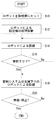
次に、図3を参照しながら、上述の本発明による飛行操縦ロボット1の使用手順について説明する。
Next, the use procedure of the above-described
図3は、何らかの要因によりパイロットが航空機100を操縦し得なくなった場合に、飛行操縦ロボット1に航空機100を操縦させる手順を例示するフローチャートである。同図に示されるように、パイロットが航空機100を操縦し得なくなったと判断された場合、残りの乗員の手によって飛行操縦ロボット1が操縦席にセットされる(S10)。この場合、図2に示されるように、飛行操縦ロボット1は、例えば、左アーム2が操縦用部材102に含まれる操舵輪102aを把持すると共に、右アーム4が操縦用部材102に含まれるスロットルレバー102bを把持する状態で操縦席に載置される。また、飛行操縦ロボット1の左レッグ6および右レッグ8は、図2に示されるように、操縦用部材102に含まれる方向舵制御用のペダル102c上に載せられる。
FIG. 3 is a flowchart illustrating a procedure for causing the
飛行操縦ロボット1が操縦席にセットされると、飛行操縦ロボット1の電源スイッチがONされ(電源が投入されていない場合)、飛行操縦ロボット1の制御コンピュータ12は、それ自体が保有しているセンサ群16からの信号に基づいて予め用意されている診断プログラムを用いて航空機100の故障診断を実行する(S12)。このように、飛行操縦ロボット1に対して、操縦席へのセット時に航空機100の故障診断を実行させることにより、適切な操縦を実行する上で必要な航空機100の作動状況に関する情報を飛行操縦ロボット1に与えることが可能となる。
When the
S12の故障診断を実行すると、飛行操縦ロボット1の制御コンピュータ12は、予め用意されている制御プラグラムの中から、航空機100の状態に応じた最適なプログラムを選択し、当該プログラムに従って、左アーム2、右アーム4、左レッグ6、右レッグ8およびマニピュレータ10を制御することにより、航空機100の自律的操縦を実行する(S14)。この際、飛行操縦ロボット1の制御コンピュータ12は、基本的に、自己が有するセンサ群16からの検出信号に基づいて航空機100の運動状態を取得し、各アクチュエータ2a,4a,6a,8aおよびマニピュレータ10に与えるべき指令信号を生成する。
When the failure diagnosis of S12 is executed, the
ここで、航空機100の操縦が飛行操縦ロボット1によって実行される場合にも、操舵輪102a、スロットルレバー102bおよびペダル102cの操作に加えて、操縦用スイッチ類104を操作することが必要となる。しかしながら、人間の手とは異なり、左アーム2および右アーム4に操舵輪102aやスロットルレバー102bを一旦把持させた後、当該把持状態を解除させ、更に、再度操舵輪102a等を把持させることは容易ではなく、左アーム2および右アーム4に操縦用スイッチ類104を操作させることは容易ではない。このため、飛行操縦ロボット1には、左右のアーム2,4に加えて、専ら操縦用スイッチ類104の操作するためのマニピュレータ10が設けられており、操縦用スイッチ類104は、マニピュレータ10によって操作される。このように、飛行操縦ロボット1に専ら操縦用スイッチ類104の操作するマニピュレータ10を設けることより、左アーム2および右アーム4の動作パターンを単純化すると共にそれぞれの作動範囲を小さくすることができるので、飛行操縦ロボット1の制御を単純化してその動作を確実なものとすることが可能となる。
Here, even when the
S14にて飛行操縦ロボット1による航空機100の操縦を開始させると、制御コンピュータ12は、航空機100が地上側の管制システム200の管制エリア内に位置しているか否か判定する(S16)。航空機100が地上側の管制システム200の管制エリア内に位置していないと判断すると(S16におけるNo)、制御コンピュータ12は、S14における航空機100の自律制御を続行する。
When the control of the
一方、S16にて航空機100が地上側の管制システム200の管制エリア内に入ったと判断されると(S16におけるYes)、飛行操縦ロボットの制御コンピュータ12は、通信装置14を介した管制システム200との交信を開始する。そして、制御コンピュータ12は、自己が有する制御プログラムと管制システム200からの指示とに従いながら、上述の左アーム2、右アーム4、左レッグ6、右レッグ8およびマニピュレータ10を制御する(S18)。つまり、本実施形態の飛行操縦ロボット1は、航空機100が地上側の管制システム200の管制エリア内に入ると、通信装置14を用いて地上側の管制システム200と交信を行い、管制システム200による支援下で航空機100を操縦する。このように、地上側の管制システム200によって飛行操縦ロボット1を支援し得るようにすることにより、パイロットによる操縦が困難となったような場合に、航空機100の安全な飛行を良好に確保することが可能となる。
On the other hand, if it is determined in S16 that the
なお、飛行操縦ロボット1は、航空機100が地上側の管制システム200の管制エリア内に入った時点から、管制システム200によって完全に遠隔制御されるものであってもよい。また、航空機100が地上側の管制システム200の管制エリア内に入った後であっても、飛行操縦ロボット1に航空機100の自律的操縦をそのまま継続させてよいことはいうまでもない。
The
S18にて管制システム200による飛行操縦ロボット1の支援が開始された後、航空機100が着陸・停止したと判断されるまで(S20におけるNo)、飛行操縦ロボット1は、自己が有する制御プログラムと管制システム200からの指示とに従いながら、航空機100を操縦する(S18)。そして、航空機100が安全に着陸・停止すると、飛行操縦ロボット1による航空機100の操縦が終了する(S20におけるYes)。
After the support of the
上述のように、飛行操縦ロボット1によれば、パイロットによる操縦が困難となったような場合であっても、航空機の安全な飛行を確保することが可能となる。そして、上述の飛行操縦ロボット1は、航空機100とは全く別個独立のものであるため、既存の航空機に対して、機体側に何らかの改良を加えることなく適用され得る。更に、将来的には、飛行操縦ロボット1に副操縦士の役割を担わせることも可能であろう。そして、上述の飛行操縦ロボット1は、次のような態様のもとでも使用され得る。
As described above, according to the
すなわち、飛行操縦ロボット1は、航空機100に設けられているセンサ群116とは独立に航空機100の運動状態を検出可能なセンサ群16を備えており、それ自体で姿勢や速度といった航空機100の運動状態を把握し得る。従って、パイロットが航空機100の操縦を主に担っている際に、飛行操縦ロボット1を例えば操縦席の一方といった適所にセットしておくことにより、飛行操縦ロボット1が自らのセンサ群16を利用して把握した航空機100の運動状態に関する情報をパイロットに対して助言的に与えることが可能となる。
That is, the
かかる態様のもとでは、飛行操縦ロボット1の制御コンピュータ12によって上述のパイロット支援プログラムが実行される。そして、この場合、飛行操縦ロボット1が取得した航空機100の操縦に関する情報は、通信装置14および106を介して航空機100の飛行制御コンピュータ110に与えられ、飛行制御コンピュータ110は、飛行操縦ロボット1からの航空機100の操縦に関する情報を音声や画像を介してパイロットに提示する。これにより、航空機100のセンサ群116や航法装置といった航空機100側の要素に何らかの不具合が生じたような場合であっても、バイロットに航空機100の操縦に関する情報を与えることが可能となるので、航空機100の安全な飛行を良好に確保することが可能となる。
Under such an aspect, the above-described pilot support program is executed by the
1 飛行操縦ロボット、2 左アーム、2a 左アーム用アクチュエータ、4 右アーム、4a 右アーム用アクチュエータ、6 左レッグ、6a 左レッグ用アクチュエータ、8 右レッグ、8a 右レッグ用アクチュエータ、10 マニピュレータ、12 制御コンピュータ、14,106 通信装置、16,116 センサ群、100 航空機、102 操縦用部材、102a 操舵輪、102b スロットルレバー、102c ペダル、104 操縦用スイッチ類、106 通信装置、110 飛行制御コンピュータ、112 操舵用アクチュエータ、114 推進装置、200 管制システム。 1 flight control robot, 2 left arm, 2a left arm actuator, 4 right arm, 4a right arm actuator, 6 left leg, 6a left leg actuator, 8 right leg, 8a right leg actuator, 10 manipulator, 12 control Computer, 14,106 Communication device, 16,116 Sensor group, 100 Aircraft, 102 Steering member, 102a Steering wheel, 102b Throttle lever, 102c Pedal, 104 Steering switch, 106 Communication device, 110 Flight control computer, 112 Steering Actuator, 114 propulsion device, 200 control system.
Claims (4)
前記航空機の操縦用部材や操縦用スイッチ類をそれぞれ操作可能な複数の操作手段と、
前記航空機に設けられているセンサ群とは独立に前記航空機の運動状態を検出するセンサ群と、
前記センサ群の検出信号に基づいて前記操作手段を制御する制御手段とを備え、
前記操作手段は、
操舵輪およびスロットルレバーを操作する左右のアームと、
操縦用スイッチ類を操作するマニピュレータと、を備え、
前記航空機の操縦席にパイロットに代わってセットされた状態で前記航空機の操縦を自律的に実行可能であることを特徴とする飛行操縦ロボット。 A flight control robot capable of controlling an aircraft,
A plurality of operating means capable of operating the aircraft control members and control switches;
A sensor group for detecting a motion state of the aircraft independently of a sensor group provided in the aircraft;
Control means for controlling the operating means based on a detection signal of the sensor group,
The operation means includes
Left and right arms to operate the steering wheel and throttle lever,
A manipulator for operating the control switches,
Flying maneuver the robot, characterized in that the cockpit of the aircraft is autonomously capable of executing the maneuver before Symbol aircraft while being set in place of the pilot.
Priority Applications (1)
| Application Number | Priority Date | Filing Date | Title |
|---|---|---|---|
| JP2005006092A JP4334483B2 (en) | 2005-01-13 | 2005-01-13 | Flight control robot |
Applications Claiming Priority (1)
| Application Number | Priority Date | Filing Date | Title |
|---|---|---|---|
| JP2005006092A JP4334483B2 (en) | 2005-01-13 | 2005-01-13 | Flight control robot |
Publications (2)
| Publication Number | Publication Date |
|---|---|
| JP2006193034A JP2006193034A (en) | 2006-07-27 |
| JP4334483B2 true JP4334483B2 (en) | 2009-09-30 |
Family
ID=36799444
Family Applications (1)
| Application Number | Title | Priority Date | Filing Date |
|---|---|---|---|
| JP2005006092A Expired - Fee Related JP4334483B2 (en) | 2005-01-13 | 2005-01-13 | Flight control robot |
Country Status (1)
| Country | Link |
|---|---|
| JP (1) | JP4334483B2 (en) |
Families Citing this family (2)
| Publication number | Priority date | Publication date | Assignee | Title |
|---|---|---|---|---|
| US10577082B2 (en) | 2016-08-12 | 2020-03-03 | Sikorsky Aircraft Corporation | Cockpit control of a fixed wing aircraft |
| CN117067228B (en) * | 2023-08-23 | 2024-03-26 | 中国人民解放军95791部队 | Robot for driving a man-machine |
Family Cites Families (2)
| Publication number | Priority date | Publication date | Assignee | Title |
|---|---|---|---|---|
| JP4506016B2 (en) * | 2000-09-19 | 2010-07-21 | トヨタ自動車株式会社 | Mobile body mounting robot and mobile body equipped with the same |
| JP3813816B2 (en) * | 2000-12-28 | 2006-08-23 | 川田工業株式会社 | Reaction force control system |
-
2005
- 2005-01-13 JP JP2005006092A patent/JP4334483B2/en not_active Expired - Fee Related
Also Published As
| Publication number | Publication date |
|---|---|
| JP2006193034A (en) | 2006-07-27 |
Similar Documents
| Publication | Publication Date | Title |
|---|---|---|
| KR101750538B1 (en) | An artificial force feel generating device for a vehicle control system of a vehicle and, in particular, of an aircraft | |
| CA2683132C (en) | Multi-axis serially redundant, single channel, multi-path fly-by-wire flight control system | |
| EP3335915B1 (en) | Stability control for operation of a convertible air - road vehicle | |
| JP7426204B2 (en) | air and land vehicle | |
| CN104176242B (en) | Flight control and control method | |
| JP4691121B2 (en) | Control system, control stick link disconnection method | |
| US10239633B2 (en) | System and method to interchange flight control inceptors in an aircraft flight control system and cockpit | |
| JP4304009B2 (en) | Unmanned aircraft control system | |
| US9828096B2 (en) | Movable control surface ejection system | |
| EP4192730A1 (en) | System and method of vtol vehicle flight control inceptors | |
| CN106314763B (en) | Method for controlling an aerodynamic device of an aircraft, associated control system and aircraft provided with such a control system | |
| CN114104269A (en) | Rudder pedal assembly for controlling aircraft and aircraft | |
| JP4334483B2 (en) | Flight control robot | |
| KR20220115540A (en) | Aircraft control system and associated aircraft | |
| CA3096596C (en) | A vehicle control system for autonomous, remotely-controlled, or manual operation of a vehicle | |
| US10562609B2 (en) | High trim demand relief | |
| EP2857312B1 (en) | Control device of aircraft steering apparatus | |
| EP3492373B1 (en) | System and method for flight mode annunciation | |
| JPH07112835B2 (en) | Aircraft control force gradient application device | |
| JP5531414B2 (en) | Maneuvering support device | |
| CN112722246B (en) | Vehicle control system for autonomous remote control or manual operation of a vehicle | |
| JP2019051755A (en) | Maneuvering system of flight device | |
| CN109866916B (en) | Electric control member, rotorcraft and method | |
| JP2022035458A (en) | Remote control system for aircraft | |
| JP2020061188A (en) | Maneuvering system of flight device |
Legal Events
| Date | Code | Title | Description |
|---|---|---|---|
| A621 | Written request for application examination |
Free format text: JAPANESE INTERMEDIATE CODE: A621 Effective date: 20060912 |
|
| A977 | Report on retrieval |
Free format text: JAPANESE INTERMEDIATE CODE: A971007 Effective date: 20090123 |
|
| A131 | Notification of reasons for refusal |
Free format text: JAPANESE INTERMEDIATE CODE: A131 Effective date: 20090210 |
|
| A521 | Written amendment |
Free format text: JAPANESE INTERMEDIATE CODE: A523 Effective date: 20090316 |
|
| TRDD | Decision of grant or rejection written | ||
| A01 | Written decision to grant a patent or to grant a registration (utility model) |
Free format text: JAPANESE INTERMEDIATE CODE: A01 Effective date: 20090616 |
|
| A01 | Written decision to grant a patent or to grant a registration (utility model) |
Free format text: JAPANESE INTERMEDIATE CODE: A01 |
|
| A61 | First payment of annual fees (during grant procedure) |
Free format text: JAPANESE INTERMEDIATE CODE: A61 Effective date: 20090623 |
|
| FPAY | Renewal fee payment (event date is renewal date of database) |
Free format text: PAYMENT UNTIL: 20120703 Year of fee payment: 3 |
|
| R150 | Certificate of patent or registration of utility model |
Free format text: JAPANESE INTERMEDIATE CODE: R150 |
|
| FPAY | Renewal fee payment (event date is renewal date of database) |
Free format text: PAYMENT UNTIL: 20120703 Year of fee payment: 3 |
|
| FPAY | Renewal fee payment (event date is renewal date of database) |
Free format text: PAYMENT UNTIL: 20130703 Year of fee payment: 4 |
|
| LAPS | Cancellation because of no payment of annual fees |