JP4332254B2 - Intelligent glove-type hand input device - Google Patents
Intelligent glove-type hand input device Download PDFInfo
- Publication number
- JP4332254B2 JP4332254B2 JP12306299A JP12306299A JP4332254B2 JP 4332254 B2 JP4332254 B2 JP 4332254B2 JP 12306299 A JP12306299 A JP 12306299A JP 12306299 A JP12306299 A JP 12306299A JP 4332254 B2 JP4332254 B2 JP 4332254B2
- Authority
- JP
- Japan
- Prior art keywords
- movement
- finger
- glove
- input device
- hand
- Prior art date
- Legal status (The legal status is an assumption and is not a legal conclusion. Google has not performed a legal analysis and makes no representation as to the accuracy of the status listed.)
- Expired - Lifetime
Links
Images


Description
【0001】
【発明の属する技術分野】
本発明は、バーチャルリアリティを利用したシステムに対してデータ入力を行う入力装置に関して、特に実際の手の動き(ジェスチャ)を計測してシステム内に取り込む3次元データを作成することができる手袋型入力装置に関し、更には手話電話や手話入力装置の入力インタフェースとして適用可能なインテリジェント型手袋型手形入力装置に関する。
【0002】
【従来の技術】
バーチャルリアリティの一形態として、表示装置上に使用者の分身(キャラクタ)を表示させ、その表示させたキャラクタを実際に使用者が動くのとほぼ同じ動きをさせることにより、使用者が表示装置に表示された仮想空間(映像空間)内に自分自身があたかも存在していると感じることができるとともに、インタラクティブに仮想空間で疑似体験ができるようなものがある。その中で、人間のより自然な動きを伝達するために、通常の生活や仕事のなかで最も役割の大きいといえる手の動き(ジェスチャ)を計測できるデータ入力用グローブ(手袋型入力装置)がある。従来知られたデータ入力用グローブは、このデータ入力用グローブの各指に対応して設けられた光ファイバ内を通る光量の変化を解析することによって各指の曲がり等を検出、つまり手の動きを計測できるようになっている。この光ファイバを用いるもの以外にも、機械リンク(例えば、ゴニオメータ等)を用いるものや、あるいは圧力や曲げによって抵抗が変わる素子(例えば、液体導電性インク等)を用いるものなどが従来から知られている。
このようなデータ入力用グローブを用いたバーチャルリアリティシステムは、テレロボティックコントロール(すなわち、オペレータによるロボットの遠隔操作)や、対話型医療シミュレーションあるいは3次元モデリングCAD(モーションキャプチャ)等の様々な分野で利用されつつある。
【0003】
ところで、人間が物体を操作する際には硬さや重さといった力の感覚(力覚)が不可欠であり、仮想空間からの力フィードバックの重要性が従来から認識されている。そこで、データ入力用グローブに、仮想空間中の対象物体に接触することによって対象物体から受けた反力を機械的に発生するためのフォースフィードバック装置が設けられることがある。このフォースフィードバック装置は、仮想空間内において仮想の手(指)が仮想対象物あるいは仮想環境(例えば、壁)等と接触した状況から得られる反力を人間側に戻すものである。つまり、何か機械的に力を発生するような装置(フォースフィードバック装置)に現実の人間の手や指が触れていて、その装置が人間に対して反力を与えることによって、人間は仮想空間内からの反力を感じ取ることができる。
【0004】
【発明が解決しようとする課題】
上述したように従来のデータ入力用グローブは、光量の変化を光センサにより検出して手の動きを計測するものであった。そのため、所定の角度以上に指が曲げられないと光量の変化を捕らえることができずに手の動きが計測されない、すなわち高精度の計測が難しい、という問題点があった。また、上述した光センサを利用したデータ入力用グローブは、指の曲げ角度に比例して光量の変化が生ずるように光ファイバにスリット(傷)を入れていたので、機械振動に弱く、また長時間使用における機械的摩耗や腐食等を避けることができず、それゆえ数年使用することによって計測に誤差を生ずるようになる、という問題点があった。さらに、このような光センサ等を用いたデータ入力用グローブは高価なものであった。
【0005】
また、上述したフォースフィードバックを行なうようにするためには、そのための機械的な機構を手の動きを計測するための光センサ等とは別々に構成しなければならなかった。そのために、フォースフィードバック機構を具えたデータ入力用グローブは大型化かつ重量化してしまい、使用者にとって非常に装着しにくく使いづらいものになる、という問題点もあった。
【0006】
また、従来、実用化されていた手袋型入力装置はいずれも極めて高価なものであり、誰でもが簡便に利用できるものではなかった。従って、現在では、未だ、安価で有効・有用な手袋型入力装置が普及しておらず、様々な分野で利用可能性があり、また、実用化が要請されているにもかかわらず、これらの要請に応えることができなかった。例えば、手袋型入力装置を用いて手形(手話における手の形態)の入力を行うことができれば、手話電話やコンピュータシステム等における手話入力装置として利用することができ、聴覚障害を持つ人々に恩恵をもたらすことができるが、現時点では、そのような手袋型手形入力装置は存在していない。
【0007】
本発明は上述の点に鑑みてなされたもので、小型かつシンプルな構造を持つと共に、高精度な分解能で手の動きの計測が可能であり、かつ、耐久性に富んだ手袋型の入力装置を提供しようとするものである。
また、製造が極めて容易なシンプルな構造でフォースフィードバックを可能とした手袋型の入力装置を提供しようとするものである。
更には、様々な技術分野・産業分野で比較的安価かつ簡便に利用することのできる手袋型入力装置を提供しようとするものである。特に、手話電話やコンピュータシステム等における手話入力インタフェースとして有利に利用することができる手袋型入力装置を提供しようとするものである。
【0008】
【課題を解決するための手段】
【0010】
本発明に係る手袋型入力装置は、使用者の手の動きを検出するため手に装着される手袋型入力装置であって、使用者の指又は手の所定部位に一端が装着され、指又は該所定部位の動きを伝達するため所定範囲にわたって延びた伝達手段と、前記伝達手段の他端を弾性的に支持するバネと、前記バネの一端を制御信号に応じて変位させることにより該バネの付勢力を該制御信号に応じて可変調節する調節手段とを具備し、前記調節手段は、制御信号によって励磁される励磁コイルと可動鉄心とを有したソレノイドを含み、可動鉄心を前記バネの一端に連結し、仮想空間内における反力に応じて前記制御信号を供給して前記可動鉄心の移動を制御し、この可動鉄心の移動量に応じて前記バネの付勢力を制御し、これによってフィードバックフォースを制御できるようにしたことを特徴とするものである。
【0011】
調節手段は、伝達手段に付された弾性手段の有する付勢力を随時に可変制御することができるように構成される。前記伝達手段は各指毎に所定の長さを保つように長さ調節されて、その一端は指の所定位置又は手の所定部位に固定的に配置される。伝達手段の反対側の先端には弾性手段が付され、伝達手段に所定のテンション(張力)を与えている。そのため、調節手段によって弾性手段の有する付勢力を随時に変化することに応じて、使用者が指の曲げ伸ばしを行うために伝達手段にかける力も変化する。すなわち、指の曲げ伸ばしは弾性手段の有する付勢力に抗して行われることから、付勢力を強くすると、それに応じて指の曲げ伸ばしが行いにくくなる。反対に、付勢力を弱くすると、それに応じて指の曲げ伸ばしが行いやすくなる。したがって、この調節手段による弾性手段の有する付勢力の制御を随時に行うことができるようにすることで、フィードバックフォースを反映した手袋型入力装置を構成できる。
【0012】
更に、使用者の指又は手の所定部位の動きを検出して、検出信号を発生する検出手段を具えていてもよい。検出手段は指又は手の所定部位の動きに応じて検出信号を発生し、調節手段はこの検出信号に応じて弾性手段の有する付勢力の制御を行うことができる。こうすると、常に指又は手の所定部位の動きに応じたフィードバックフォースを反映することができる。また、指又は手の所定部位の動きを検出するための機構とフィードバックフォースを反映させるための機構とを一体的に構成することができ、当該手袋型入力装置をシンプルな構造を持った小型のものとすることができる。
【0013】
この発明における好ましい実施例としては、前記検出手段は所定の交流信号によって励磁される1次巻線及び前記1次巻線と磁気的に結合される2次巻線を含むコイル部と、磁気応答部材とを有し、前記伝達手段の移動に応じた出力信号を該2次巻線より得ることによって手の動きの検出信号を得るように構成することがあげられる。すなわち、検出手段を構成するコイル部及び磁気応答部材は、前記伝達手段の所定の範囲での移動に応じて、前記コイル部と前記磁気応答部材との相対的な位置関係が変化するように構成する。
【0014】
また、この発明における好ましい実施例としては、前記調節手段は制御信号によって励磁される励磁コイルと可動鉄心とを有したソレノイドを含み、可動鉄心を前記弾性手段に連結し、仮想空間内における反力に応じて前記制御信号を供給して前記可動鉄心の移動を制御し、この可動鉄心の移動量に応じて前記弾性手段の付勢力を制御するように構成することがあげられる。
【0015】
以上から明らかなように、本発明によれば、製造が極めて容易になるような小型かつシンプルな構造を持つと共に耐久性に富み、かつ、高精度な分解能で手の動きの計測が可能な手袋型入力装置を提供することができる。また、製造が極めて容易なシンプルな構造でフォースフィードバックを可能とした手袋型入力装置を提供することができる。さらに、安価な手袋型入力装置を提供することができる。
【0016】
【発明の実施の形態】
以下、添付図面を参照してこの発明の実施の形態を説明する。
【0017】
図1は、本発明に係る手袋型入力装置を用いたバーチャルリアリティ(仮想現実)を利用したシステムの一実施例を概略的に示したシステム概略図である。図1に示したバーチャルリアリティシステムは、手袋型入力装置1とコンピュータ2とディスプレイ3等から構成される。バーチャルリアリティシステムはこれら以外のハードウェアを有する場合もあるが、ここでは必要最小限の資源を用いた場合について説明する。
【0018】
当該実施例における手袋型入力装置1(以下、データ入力用グローブと呼ぶ)は、使用者の左手に装着されて使用されるものを例に示している。つまり、左手用のデータ入力用グローブ1である。勿論、データ入力用グローブ1は右手に装着できるように形成されてもよい。また、左右の手にそれぞれ別々のデータ入力用グローブ1を装着して同時に使用してよいことは言うまでもない。ディスプレイ3は、仮想対象物(図では球)を含めた仮想空間を表示し、使用者はディスプレイ3により仮想空間を視覚できるようになっている。このようなバーチャルリアリティシステムにおいて、使用者はデータ入力用グローブ1を装着した状態で左手の各指を動かすと、データ入力用グローブ1は使用者の左手の動き(各指の動き)に合わせて各指の曲がり具合等の変化を計測して、この計測した値をコンピュータ2に入力可能な数値データに変換する。コンピュータ2は中央演算処理装置(CPU)を具えた、例えばパーソナルコンピュータのようなものであって、データ入力用グローブ1から得られる数値データを解析して、ディスプレイ3の画面X上に表示されている仮想空間内の手(各指)を実際に行われた使用者の手の動き(各指の動き)にあわせて動かしながら表示する。データ入力用グローブ1とコンピュータ2間及びコンピュータ2とディスプレイ3間には、前記数値データや制御データ等を送受信できるように信号伝送手段4で各々結合されている。
【0019】
なお、ディスプレイ3は図示したようなものに限らず、立体ホログラムを用いて表示するものや、あるいはHMD(Head Mounted Displayの略)等、どのようなものであってもよい。HMDは液晶等を用いた表示装置であり、使用者はこのHMDを眼前の視野を遮るように装着することで仮想空間を視覚できる。さらに、ハーフミラー等を用いて、使用者の眼前の風景に仮想の像を重畳して視覚できるものもある。
また、信号伝送手段4は図示したような有線のものでなくてもよく、無線等ワイヤレスのものであってもよい。また、このようなバーチャルリアリティシステムは単体で用いられるだけでなく、当該バーチャルリアリティシステムと現実のロボットシステム等を組み合わせて、現実的なロボット等の操作制御を行うことができるようにしてよいことは言うまでもない。さらに、コンピュータ2やディスプレイ3を当該入力装置1とは別々に構成したが、一体的に構成してもよい。
【0020】
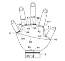
図2は、本発明に係るデータ入力用グローブの一実施例を概略的に示した全体概略構成図である。ただし、説明を理解しやすくするために当該データ入力用グローブを使用者に装着した状態で、かつ、データ入力用グローブの内部的な構造のみを示した。図3は、図2に示したデータ入力用グローブの1本の指についてのみ拡大して詳細に示した一部拡大図である。
【0021】
当該データ入力用グローブ1は、各指の曲がり具合を検出するための検出器10が各指に対応するように装着されて、固定ベルト5によって手首の部分で固定される。自在バンド6はその長さを自由に調整することができ、指を取り囲むようにしてデータ入力用グローブ1を固定する(図3参照)。この際、各指の関節位置とデータ入力用グローブ1の関節位置との相対的位置にずれが生じないように各指の関節部分の太さにあわせて固定する。ガイド7は、中空の例えば円柱や円錐あるいは直方体といったような適宜の形状に形成され、その中空部分をワイヤ8が通っている。そのため、指が曲げられた際でもワイヤ8は各関節部分で引っかかることなく滑らかにY方向に自由に往復動できるようになっている。ワイヤ8は、各指に沿って各指の第1関節部分の自在バンド6に設けられた長さ調節機構9から各関節部分のガイド7を通って検出器10まで形成される。長さ調節機構9は、ワイヤ8の長さを指の長さにあわせて自由に調節し、ワイヤ8の一端を固定するものである。固定ベルト5には検出器10が配置され、この検出器10は指の動きに合わせてワイヤ8が指先及び手首間をY方向に往復移動するとその動きを検出できるようになっている。
【0022】
なお、図2及び図3では各指にワイヤ8を1本のみ構成した例を示したが、図4Aに示すように各指の関節毎にワイヤ8を複数具えるように構成してもよい。こうすることにより、ワイヤを1本のみ構成した場合と比較してより各指の動きを詳細に捉えることができるようになる。勿論、ワイヤ8に対応して検出器10等を複数設けることは言うまでもない。また、ワイヤ8はこれに限られるものではなく、糸のようなものであってもよい。例えば、図示の人差し指の例では、ワイヤ8aが第1関節、ワイヤ8bが第2関節、ワイヤ8cが第3関節の動きを各々個別に伝導するものであり、検出器10a、10b、10cで各々の動きを検出する。
【0023】
また、指の動きを検出するためのワイヤ8の配置は上述の例に限らず、例えば、各指の間(すなわち、各指の股)や手の甲の摺曲部あるいは手首等に適切にワイヤ8を配置するようにしてもよい。すなわち、各指の間の開き具合や、手の甲の褶曲具合、手首の曲げ状態等を検出しうるようにワイヤ8を配置してもよい。これを図示すると、例えば図4Bに示す図のようになる。すなわち、各指の間や、親指と小指間、及び手首の部分(固定バンド5上)にワイヤ81〜86を各々具えるように構成し、これに対応するように検出器101〜106を配置する。各ワイヤ81〜86は、各々長さ調節機構91〜96によりその長さが一定に保たれる。
各指の間のワイヤ81〜84は隣りあった各指間の開閉動作を個別に伝達するものであり、検出器101〜104でその動きを検出する。例えば、図示の親指と人差し指の間が開かれると、ワイヤ81がその動きを伝達して、検出器101で親指と人指し指の開閉状態を検出する。親指と小指間のワイヤ85は手の甲の褶曲具合を伝達するものであり、検出器105でその動きを検出する。例えば、手のひらを握ったり、あるいは親指と小指とを接触させようと互いの指を近づけたりすると、ワイヤ85がその動きを伝達して、検出器105で手の甲の褶曲状態を検出する。ワイヤ86は手首の曲げ状態を伝達するものであり、検出器106でその動きを検出する。ワイヤ86は、一方の先端が手の甲の所定位置に位置するように固定ベルト5上に配置されて、手首の曲げ動作を伝達し、検出器106で手首の曲げ状態を検出する。
【0024】
なお、上述の例では検出器101〜105を自在バンド6上に配置したが、固定バンド5上に配置するようにしてもよい。その場合には、検出器101〜105の位置に例えば滑車(ローラ)などを配置し、ワイヤ81〜85の一端が滑車を介して固定バンド5側の検出器まで届くように構成する。また、親指と小指間だけにワイヤ85を配置したものを図示したが、これに限らず、親指と薬指間や小指と人差し指間、あるいは人差し指と薬指間等に適宜にワイヤを配置して、手の甲の褶曲具合を検出できるようにしてもよい。また、これらを複数組み合わせて用いてもよい。
また、上述した図2や図4Aに示した実施例と図4Bに示した実施例とを適宜組み合わせて構成してよいことは言うまでもない。
【0025】
図3に戻り、ワイヤ8の先端は長さ調節機構9と結合しており、他方の先端はセンサ部11を通って引っ張りばねからなるコイルばね12と結合している。また、コイルばね12のもう一方の先端はテンション調節機構13に固定されている。すなわち、ワイヤ8はこのコイルばね12の有する付勢力によって、常に所定のテンションがかかった状態に保たれる。テンション調節機構13は、上位コントローラ(コンピュータ2等)から与えられる制御信号に応じて、コイルばね12によるテンションを可変調節するものであり、フォースフィードバックを実現するものである。その詳細は後述する。この実施例では、指を曲げていない状態ではコイルばね12が静的状態を保つように調節され、指を曲げるとそれに伴ってコイルばね12の有する付勢力に抗してワイヤ8が引っ張られるようになっている。検出器10は、このワイヤ8が引っ張られることによるワイヤ8の変位量をセンサ部11で検出して指の動きを検出する。さらに、検出器10はワイヤ8の変位の速度あるいは加速度を検出して、指の動きの速さあるいは加速度を検出するようにしてもよい。
【0026】
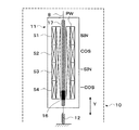
ここで、指の動きの検出について具体的な実施例を用いて説明する。図5は、ワイヤ8の変位を検出する位置検出手段すなわち検出器10の一実施例を概略的に示した概略構成図である。当該検出器は、図2及び図4に示すように各指(あるいは各指の関節)毎に各々対応して構成される。
【0027】
この実施例において、センサ部11は、例えば特開昭10−153402号に示されたような誘導式の直線位置検出装置を用いて構成されており、ワイヤ8の側に所定間隔で固定的に設けられた1又は複数の磁気応答部材15と、固定ベルト5の側に固定的に設けられた1次巻線PWおよび2次巻線S1〜S4とからなる。1次巻線PWおよび2次巻線S1〜S4は、非磁性体からなるチューブ14の所定においてその周囲に巻回されており、サイン相、コサイン相、マイナス・サイン相、マイナス・コサイン相にそれぞれ対応する4つの2次巻線S1〜S4は、変位方向に関してそれぞれ異なる位置に配置されている。例えば、1つの2次巻線(S1〜S4)がカバーする範囲の長さをP/4とすると、4つの2次巻線S1〜S4の全体ではPの長さをカバーする。また、すベての2次巻線S1〜S4をカバーするように1相交流励磁される1次巻線PWが設けられている。図示の例では、1次巻線PWの外側に2次巻線S1〜S4が巻回されているがこれは逆であってもよい。また、図示の例では、各2次巻線S1〜S4のコイル長がP/4のように描かれているが、これよりも短くてもよい。その場合、各2次巻線S1〜S4の間に分割して1次巻線PWを挿入してもよい。
【0028】
ワイヤ8は例えばナイロン糸のような強靱な非磁性かつ非導電性の糸からなっており、そのうち前記チューブ14内に入っている及び侵入する可能性のある所定の範囲において、1又は複数の磁気応答部材15が所定間隔で固定的に設けられている。これにより、指の動きに連動してワイヤ8が変位すると、これに応じて磁気応答部材15が変位し、センサ部11において、1次及び2次巻線に対する磁気応答部材15の相対的位置が変位する。この磁気応答部材15の相対的変位に応じた出力を2次巻線S1〜S4から得ることにより、指の動きを検出することができる。磁気応答部材15としては、鉄等の磁性体または銅あるいはアルミニウム等の良導電体を使用することができる。磁気応答部材15として磁性体を用いた場合は、該磁気応答部材15が近接する箇所で1次及び2次巻線間の磁気結合度が上がり、対応する2次巻線に誘導される電圧レベルが上がる。一方、磁気応答部材15として良導電体を用いた場合は、該磁気応答部材15が近接する箇所で渦電流損によって1次及び2次巻線間の磁気結合度が下がり、対応する2次巻線に誘導される電圧レベルが下がる。どちらの場合でも、磁気応答部材15の近接に相関する誘導出力電圧を2次巻線S1〜S4から得ることができる。
【0029】
例えば、1つの磁気応答部材15のサイズは、長さにしてP/2若しくはその前後の適宜の値又はP/2未満の適宜の値であり、複数の磁気応答部材15を設ける場合は、長さPの周期でこれを繰り返して設ける。これにより、ワイヤ8の長さPの変位に対応して、センサ部11の2次巻線S1〜S4の誘導出力電圧は1周期の変化を示す。指の動きに対応したワイヤ8の変位量は比較的わずかなものであるので、その最大変位量が前記長さPを越えないようにセンサ部11の各巻線の寸法を設計すれば、指の動きに対応したワイヤ8の変位量を長さPの範囲内のアブソリュート値で検出することができる。もちろん、ワイヤ8の変位量が前記長さPを越える場合であっても、磁気応答部材15を長さPの周期で複数設けているので、この変位を検出することができる。その場合は、周知のように、長さPを越えた回数(周期数)を別途演算等で求めることにより、長さPを越えたワイヤ8の変位量を検出することが可能である。なお、磁気応答部材15の形状は、図示のような細長の円柱状に限らず、球状あるいは楕円球状等適宜の形状であってもよいのは勿論である。なお、図示の都合上、各巻線を長く描いているが、実際は、もっと短く、かなり小型化される。
【0030】
センサ部11における1次及び2次巻線はかなり小型のものになるため、ワイヤ8の変位時に磁気応答部材15のでっぱりが巻線等何かにひっかかることがあるかもしれない。そのような懸念を除去するために、1次及び2次巻線を巻回しているチューブ14は、巻線の全長よりもある程度前後に長くし、すべての磁気応答部材15の移動範囲をカバーしうるようにするとよい。これによって、ワイヤ8の動きに伴う磁気応答部材15の動きがチューブ14によって保護され、スムーズとなる。勿論、ワイヤ8における磁気応答部材15の配置箇所全体を非磁性樹脂等で薄くコーティングして滑らかにしてもよい。
【0031】
ワイヤ8の末端はコイルばね12の一端(可動端)に固定され、該コイルばね12の他端(固定端)は適宜の手段で基部(つまり固定ベルト5)に対して固定される。なお、後述するようにテンション調節機構13を具備する場合は、該コイルばね12の他端(固定端)がテンション調節機構13で所定位置に固定(半固定)され、かつ、その固定位置が上位コントローラからの制御信号に応じて可変されることにより、コイルばね12のテンションが調節され、ワイヤ8を介して指に加わる負荷荷重が調節されることとなる。すなわち、制御信号に応じて任意の力覚提示を為すことができる。勿論、テンション調節機構13を具備しない形態で本発明を実施することも可能である。
【0032】
図5に示した実施例においては、以下に説明するレゾルバ原理に従う位置検出処理によって、指の動きに応じた位置検出出力を得るのに適している。
図6は、センサ部11において、レゾルバ原理に従う位置検出処理を行うために採用する、1次巻線PW及び2次巻線S1〜S4の結線状態を示す図である。
【0033】
1次巻線PWは1相の交流信号(便宜上、sinωtで示す)によって励磁される。各2次巻線S1〜S4の配置と磁気応答部材15の配置との関係によって、概ね、範囲Pにおける磁気応答部材15の移動を、0度≦θ≦360度、なる角度表示で示すとすると、サイン相の2次巻線S1における誘導出力の振幅関数はsinθで表わすことができ、次のコサイン相の2次巻線S2における誘導出力の振幅関数はcosθで表わすことができ、次のマイナス・サイン相の2次巻線S3における誘導出力の振幅関数は−sinθで表わすことができ、次のマイナス・コサイン相の2次巻線S4における誘導出力の振幅関数は−cosθで表わすことができることによる。換言すれば、概ねそのような関係が得られるように設計する。1つおきに配置された2次巻線S1とS3は差動接続されて、第1の出力交流信号Aを生じる。もう一方の1つおきに配置された2次巻線S2とS4も差動接続されて、第2の出力交流信号Bを生じる。
【0034】
よって、磁気応答部材15の相対的変位に応じて、一方の2次巻線S1,S3の差動接続から得られる第1の出力交流信号Aはサイン関数の振幅関数sinθを持つもの、つまりA=sinθsinωtで表わすことができるものとなり、他方の2次巻線S2,S4の差動接続から得られる第2の出力交流信号Bはコサイン関数の振幅関数cosθを持つもの、つまりcosθsinωtで表わすことができるものとなる。
【0035】
こうして、図5及び図6のような配置及び巻線構成によれば、従来知られたレゾルバにおいて得られるのと同様の、同相交流であって2相の振幅関数を持つ2つの出力交流信号(サイン出力とコサイン出力)をデータ入力用グローブ1において得ることができることが理解できる。従って、本実施例の検出器10において得られる2相の出力交流信号(A=sinθ・sinωtとB=cosθ・sinωt)は、従来知られたレゾルバの出力と同様の使い方若しくは処理をすることができる。例えば、適切なディジタル位相検出回路30を使用して、上記2相の出力交流信号A,Bにおけるサイン関数sinθとコサイン関数cosθの位相値θをディジタルで測定することができる。例えば特開平9−126809号に示されたような位相検出方式を使用することができる。これにより、連続的な指の動きを高分解能かつアブソリュートで検出することができる。この場合、位相検出回路30は専用集積回路及び/又はマイクロプロッセッサ等を含む回路構成とすることができ、これを使用者の固定ベルト5の側に設け、信号伝送手段4を介して上位のコンピュータ2に接続するようにするとよい。そのように、使用者の側にマイクロプロッセッサ等を具備することによって、様々な付加的な機能を実現しうるインテリジェントなデータ入力用グローブを構成することができる。なお、位相検出回路30はディジタル方式に限らず、アナログ方式のものであってもよい。
【0036】
なお、図5の構成において、図7に示すように、1次巻線と2次巻線の関係を逆にして、公知の位相シフトタイプ位置検出器のように構成してもよい。すなわち、4つの巻線S1〜S4を1次巻線とし、巻線PWを2次巻線とする。この場合、一方の差動接続された1次巻線S1,S3の対を例えばサイン相の交流信号sinωtによって励磁し、他方の差動接続された1次巻線S2,S4の対を例えばコサイン相の交流信号cosωtによって励磁する。そうすると、1次巻線S1,S3による2次側の誘導出力は前記から例えばsinθ・sinωtに相当するものとなり、また、1次巻線S2,S4による2次側の誘導出力は前記から例えばcosθ・cosωtに相当するものとなる。よって、2次巻線PWに得られるこれらの合成出力は、指の動きに応じた電気的位相シフトθを含む信号(例えばこれをsin(ωt+θ)で示す)となる。この出力信号sin(ωt+θ)における電気的位相シフトθを公知の位相測定回路で、ディジタル的に又はアナログ的に検出するようにすればよい。この場合も、連続的な指の動きを高分解能で検出することができる。
【0037】
更に、2次巻線S1〜S4の出力に基づき指の動きの検出データを具体的に得るための構成は、上記例に限らず、他の適宜の構成を用いてよい。
例えば、最も、単純には、各2次巻線S1〜S4の出力レベルを単純に比較して、最もレベルの低い1つの2次巻線(S1〜S4のいずれか)が配置されている位置をワイヤの変位量として検出するやり方がある。ただし、この場合は、Pの範囲を4分割した分解能でしか検出することができない、という不利がある。このような発想の変形としては、2次巻線の数が1個のみ、又は4個以上でも4個未満でもよい、ということになる。指が伸ばされている状態(すなわち、ワイヤが変位していない状態)若しくは指が曲げられている状態(すなわち、ワイヤが変位した状態)のいずれかのみを検出する場合、そのような実施の形態も有りうる。すなわち、2次巻線の数は4個に限ることなく、1又は任意の複数であってよい。あるいは、2個の2次巻線のみを差動接続して設け、差動トランスのように、ワイヤの連続的な移動位置に対応するアナログ電圧を得ることも可能である。
【0038】
図8は、検出器10におけるセンサ部11の別の実施形態を示すものである。
この例においては、ワイヤ8の側には所定位置に永久磁石16が設けられており、指の動きに応じたワイヤ8の変位に従って永久磁石16が、1次及び2次巻線PW,S1〜S4に対して相対的に変位する。1次及び2次巻線PW,S1〜S4の中心空間内には、長さPの全域にわたって磁性体コア17が固定的に設けられる。永久磁石16は、磁性体コア17に沿ってその近傍を、ワイヤ8の変位に伴って移動するように配置されている。磁性体コア17は、比透磁率が大きく、保磁力の小さな珪素鋼などの磁性体からなり、その形状は細長の円柱状であってもよいし、珪素鋼板を積層して形成された細長の直方体形状等、適宜の形状であってもよい。この磁性体コア17の周囲に1次巻線PW及び2次巻線S1〜S4が所定の配置で巻回されている。磁性体コア17と1次巻線PW及び2次巻線S1〜S4は適当な非磁性ケーシングに収納されて、固定バンド5の所定位置に固定的に配置される。なお、図示の都合上、各巻線の径を大きく、また、磁性体コア17を太く、描いているが、実際は、これらをかなり細くすることができるので、これらを収納した非磁性ケーシングは磁石16等に比べてかなり細い(薄い)ものである。
【0039】
このような構成によっても、既に上述した別の実施例と同じようにして1次巻線PWを1相の交流信号によって励磁することにより、2次巻線S1〜S4に位置検出出力信号を出力させ、これにより指の動きを検出できるようになる。
すなわち、磁石16が近接していない限り、磁性体コア17の存在によって1次巻線PWと2次巻線S1〜S4との間の磁気結合度は大であり、2次巻線S1〜S4からは大きなレベルの誘導出力が得られる。しかし、長尺の磁性体コア17のいずれかの箇所に対して、そのときのワイヤ8の位置に応じて磁石16が近接すると、その箇所では、該磁石16から発される磁束を強く受け、磁気飽和状態となる。換言すれば、そのように磁石16が近接した磁性体コア17の箇所において部分的に磁気飽和状態となるように磁石16の性能及びサイズ等を決定するものとし、また、それに応じた適切な誘導出力の変化が得られるように、各巻線PW,S1〜S4のコイル長、巻数等を設定するものとする。磁気飽和状態となった磁性体コア17の箇所では、1次PW及び2次巻線S1〜S4間の電磁誘導性能に関しては磁性体コア17が存在していない空状態と等価となり、1次PW及び2次巻線S1〜S4間の磁気結合度は低下する。よって、磁石16の近接に応じた、つまりワイヤ8の変位に応じた、誘導出力信号が各2次巻線S1〜S4から得られることになる。基本的にはこのような原理で、2次巻線S1〜S4の出力に基づきワイヤ8の変位量、すなわち、指の動きを検出することができることになる。
【0040】
こうして、ワイヤ8の変位に応じて移動する永久磁石16が近接する磁性体コア17の特定箇所で磁気飽和状態となり、その箇所に対応する1次巻線PWと2次巻線間S1〜S4の磁気結合度が低下する。従って、1次巻線PWと2次巻線間S1〜S4の磁気結合が指の動きに応じて変化され、これにより、ワイヤ8の変位量に応じて振幅変調された誘導出力交流信号が、各2次巻線S1〜S4に誘起されることになる。この図8の例においても、先にあげた実施例と同様に位相検出回路を介することにより、当該実施例においても指の動きを検出することができる。勿論、当該実施例においても、上述のレゾルバ型の位置検出だけでなく、位相シフト型の位置検出ができることは言うまでもない。
【0041】
センサ部11における1次及び2次巻線の数及び配置等は、上記各実施例に示したものに限らず、適宜に変形可能である。
【0042】
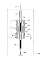
次に、フォースフィードバック機能を実現するテンション調節機構13を具えたデータ入力用グローブの一実施例について図9により説明する。
図9において、テンション調節機構13は、コイルばね12の他端(固定端)に連結されたストッパ21と、該ストッパ21を矢印F方向に駆動するための電磁ソレノイド20とを含んでいる。ストッパ21の所定個所には鍔状またはその他適宜の形状の突起部21aが形成されている。ストッパ21の先端はソレノイド20のプランジャ(可動鉄心)19に連結されている。所定位置に固定ブロック18が配置されており、コイルばね12の力によりストッパ21が矢印Fとは反対方向に駆動されるとき、ストッパ21の突起部21aが固定ブロック18によって係止される。すなわち、電磁ソレノイド20を付勢していないとき、コイルばね12の力によりストッパ21が矢印Fとは反対方向に付勢され、ストッパ21の突起部21aが固定ブロック18によって係止され、その位置に対応してコイルばね12の他端(固定端)が固定される。通常は、ソレノイド20が付勢されていない状態で使用され、フィードバックフォースを付加するとき、上位コントローラ(例えばコンピュータ2)から与えられる制御信号によってソレノイド20を付勢する。これにより、プランジャ19が矢印F方向に駆動され、コイルばね12が同方向に伸ばされて、ワイヤ8に対する引っ張りテンション(つまりコイルばね12による矢印F方向への付勢力)が増大する。これによって、手指に対してフィードバックフォースを与えることができる。通常のソレノイド20は1個の励磁コイル20aのみからなる。本実施例においても、1個の励磁コイル20aのみからなるソレノイド20を用いて、フィードバックフォースを1段階でオン・オフ制御するだけであってもよい。しかし、図示の例では、フィードバックフォースを多段階制御できるようにするために工夫をした例が示されている。すなわち、図示の例では、ソレノイド20において3つの励磁コイル20a,20b,20cが順次縦続配置されており、各励磁コイル20a、20b、20cを順次に切換えて通電することにより、プランジャー19が順次吸引されて矢印F方向に直線的に順次移動するように構成されている。つまり、励磁コイル20a、20b、20cの順に励磁することによって、プランジャー19は順に右から左の位置まで3段階に位置を移動する。これを図で示すと、図10A〜10Cのようである。図10Aは右側の励磁コイル20aに通電した際の概念図、図10Bは中央の励磁コイル20bに通電した際の概念図、図10Cは左側の励磁コイル20cに通電した際の概念図である。
【0043】
ここで、上述のソレノイドを用いたフォースフィードバック機構の動作について簡単に説明する。
通常の状態、すなわち、各励磁コイル20a、20b、20cに通電していない場合においては、プランジャー19は右端の位置に保持され、コイルばね12は伸ばされていない状態である(図9参照)。そして、例えば使用者が指を曲げる動作を行うと、ストッパ21によりコイルばね12の一端が所定の基準位置Aに位置付けられ、コイルばね12はワイヤ8を介して指の曲げに応じた分だけ引っ張られる。この状態で励磁コイル20aのみに通電すると、プランジャー19は励磁コイル20aに吸引されて、左方向へ1段階移動する(図10A参照)。すると、コイルばね12の一端が基準位置Aから左側へ移動し、励磁前に比べてコイルばね12が伸ばされた状態となって付勢力が強く働くことから、使用者はより強い力を加えないと励磁前と同じ指の曲げ状態を保持することができない。あるいは、使用者がより指を深く曲げようとするには、励磁コイル20aに通電していない状態で指を曲げる場合に比較して、コイルばね12の有する付勢力に抗する力がより多く必要となる。次に、励磁コイル20bのみに通電すると、プランジャー19は励磁コイル20bに吸引されて、左方向へ1段階移動する(図10B参照)。さらに、励磁コイル20cのみに通電すると、プランジャー19は励磁コイル20cに吸引されて、左方向へさらに1段階移動する(図10C参照)。こうして、プランジャー19が左方向へ移動してコイルばね12が引き伸ばされていくことに伴って、コイルばね12の有する付勢力に抗するための力はより強い力が必要とされる。すなわち、コイルばね12の付勢力を各励磁コイル20a、20b、20cの励磁によって調節できるようになっている。
【0044】
そこで、例えば使用者が受けるであろう仮想対象物又は仮想環境からの反力をコンピュータ2(図1参照)によりその都度計算させ、この計算結果に比例して各励磁コイル20a、20b、20cを通電するように構成すれば、随時にコイルばね12の付勢力を変化させることができ、使用者は指を動かしたときに可変のフォースフィードバックを受けたような仮想状態を得ることができるようになる。例えば、バーチャルリアリティによって指で物をつかんだとき、フィードバックフォースが弱い場合は軟らかいものをつかんだ感覚を得ることができ、フィードバックフォースが強い場合は硬いものをつかんだ感覚を得ることができる。
【0045】
なお、各励磁コイル20a、20b、20cの順次の切換えにあたっては、切換えタイミングや通電する電流値等を適宜に制御して、プランジャー19が段階的に動作できるようにすることは勿論である。また、本実施例においては励磁コイルを3個だけ構成したものを示したがこれに限らず、励磁コイルは少なくとも1個以上あればよい。ただし、できるだけ数多く励磁コイルを設けたほうが、より細かいフォースフィードバック制御を行うことができる。さらに、検出器10においてセンサ部11とテンション調節機構13を一体的に設けたものを示したが、どちらか一方を具備してもよい。勿論、フォースフィードバックは上述したソレノイド20による方法だけに限られるものではなく、例えばモータ等適宜のアクチュエータを用いてもよい。
【0046】
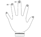
また、本発明におけるデータ入力用グローブの一実施例として、手話手形を入力するための手袋型手形入力装置として構成する場合は、例えば感圧センサや接触センサ等を各指先毎に配置してもよい。図11は、そのような構成を用いたデータ入力用グローブの一実施例を示す全体構成概略図である。ただし、指先のセンサ以外の図示は省略している。各指先には例えば感圧センサ22が配置され、当該感圧センサ22毎に各指先の接触状態を計測することができるようになっている。手話手形では指先を他方の手に接触させる形態があるため、感圧センサ22によってそのような手形を検出することができる。また、指先の接触状態を検出して、この接触の強さを例えば仮想対象物又は仮想環境からの反力を付加する制御信号として用いるようにしてもよい。
【0047】
さらに、各指の曲げ伸ばしだけでなく各指の接触状態や接触位置を検出することにより、各指の位置関係を的確に捉えて、使用者が為している手話手形を判定するようにしてもよい。例えば、使用者の指先だけでなく使用者の手の所定部分、つまり手のひらや手の甲あるいは各指の側面といった部分にも感圧センサ22等を配置して、各感圧センサ22からの接触検知信号の組み合わせから手話手形の判別を行うようにしてもよい。手話手形では単に指先を他方の手に接触させる形態以外にも、指先と手のひらや手の甲とを接触させたり、あるいは左右の指をクロスする等の複雑な形態がある。そこで、使用者の指先及び/又は手の所定部分に感圧センサ22を設け、その部分での接触を検出できるようにする。そして、各感圧センサ22から得られた検出信号を上位コントローラ(例えばコンピュータ2)に与え、上位コントローラは与えられた検出信号の組み合わせから左右の手や各指とがどのような位置関係(どのような接触状態)にあるかを判定して、手話手形を検出する。
【0048】
なお、各感圧センサ22から得られた検出信号の組み合わせの判定を、上述したようにデータ入力用グローブとは別々に構成されたコンピュータ2側で実行させてもよいし、あるいはデータ入力用グローブの例えば固定ベルト5にCPU等を具えたマイクロコンピュータを設けて、当該マイクロコンピュータに各感圧センサからの検出信号を入力して手話手形を検出するようにしてもよい。
【0049】
なお、上述した各実施例においては、指先側にワイヤ8を固定して手首側に設けた検出器10によってワイヤ8の動きを検出するようにしたが、これに限らず、反対に手首側にワイヤ8を固定して指先側に検出器10を設けるように変更することも可能である。
また、センサ部11における1次及び2次巻線PW、S1〜S4と磁気応答部材15又は磁石16との関係は、上述した実施例に限らず、1次及び2次巻線PW、S1〜S4側をワイヤ8の所定位置に配置し、磁気応答部材15又は磁石16側を検出器10の側に固定的に設けるようにしてもよい。
また、センサ部11は誘導型のものに限らず他の構成のものを用いてもよい。
また、弾性付勢手段としては、コイルばね12に限らず、ゴムのような伸縮性のある適宜の弾性部材を用いてもよい。
【0050】
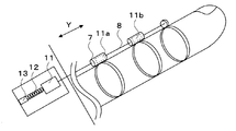
なお、センサ部11は手首側(又は指先側)の1箇所だけに(すなわち、検出器10として一体的に)構成されるものに限らず、各ガイド7毎に各々設けるようにしてもよい。これを図示すると、図12に示す図のようになる。すなわち、各関節毎に配置されたガイド7において、例えば、図5に示したような1次及び2次巻線PW、S1〜S4と磁気応答部材15とからなるセンサ部11a、11bを各々配置する。これにより、各センサ部11、11a及び11bによって各関節毎における指の動きを検出することができ、センサ部11、11a及び11bの検出値から各関節毎の曲がり具合等(つまり、指全体の外形)の判定を行うことができる。こうして、各指1本ずつのワイヤ8のみで複数の関節の曲げ具合を検出することができるようになる。
なお、この場合において、上述した位相検出回路30(図7参照)を各センサ部11、11a、11b毎に各々設けてもよいが、1つの位相検出回路30を複数のセンサ部11、11a、11bで共用して用いるようにしてもよい。
【0051】
本発明は、様々な技術分野・産業分野で比較的安価かつ簡便に利用することのできる手袋型入力装置として、広範囲に応用することができる。特に、インテリジェント型手袋型手形入力装置として構成することにより、手話電話やコンピュータシステム等における手話入力インタフェースとして有利に利用することができる。更には、各種のバーチャルリアリティ空間での手袋型フォースフィードバックインタフェースとして利用可能である。例えば、医療教育現場における触診などの教程をバーチャルリアリティ化するインタフェース、バーチャルモールでの商品を手にとった感覚等をバーチャルリアリティ化するインタフェース、新素材合成用バーチャルリアリティシミュレータの入出量インタフェース、バーチャルリアリティを用いたネットワークやプログラム管理システムの入出力インタフェース、CSCW(分散協調作業)におけるモデリング用入出力インタフェース、などに利用できる。また、遠隔ロボット制御のためのバイラテラルインタフェースとして利用可能である。例えば、原子力プラント、宇宙空間などの極限環境における遠隔ロボットコントローラ、アールキューブプロジェクト用入出力装置、遠隔手術用入出力インタフェース、手術用マイクロロボット制御のための入出力インタフェース、などに利用できる。
【0052】
【発明の効果】
以上の通り、この発明によれば、小型かつシンプルな構造を持つと共に、広い範囲にわたって連続的に高精度な分解能で手の動きが検出可能な手袋型入力装置を提供することができる。また、非接触の検出方法により手の動きを検出させることができるようになるので、摺動摩耗の心配のない耐久性に富んだ手袋型入力装置を提供することができる。更には、製造が極めて容易なシンプルな構造でフォースフィードバックを可能とした手袋型入力装置を提供することができる。
【図面の簡単な説明】
【図1】 本発明に係る手袋型入力装置を用いたバーチャルリアリティを利用したシステムの一実施例を示すシステム概略図である。
【図2】 本発明に係る手袋型入力装置の一実施例の全体概略構成を示す概略図である。
【図3】 図2に示した手袋型入力装置の1本の指についてのみ拡大して示す一部拡大図である。
【図4A】 本発明に係る手袋型入力装置の別の実施例の全体概略構成を示す概略図である。
【図4B】 本発明に係る手袋型入力装置のさらに別の実施例の全体概略構成を示す概略図である。
【図5】 本発明に係る手袋型入力装置におけるセンサ部の一実施例を拡大して示した断面図である。
【図6】 本発明に係る手袋型入力装置のセンサ部における1次及び2次巻線の結線例を示す図である。
【図7】 本発明に係る手袋型入力装置のセンサ部における1次及び2次巻線の別の結線例を示す図である。
【図8】 本発明に係る手袋型入力装置におけるセンサ部の別の実施例を拡大して示した断面図である。
【図9】 本発明に係る手袋型入力装置におけるフォースフィードバック機能を実現する機構の一実施例を拡大して示した断面図である。
【図10A】 図9に示したフォースフィードバック機構において、右端の励磁コイルに通電した際の説明図である。
【図10B】 図9に示したフォースフィードバック機構において、中央の励磁コイルに通電した際の説明図である。
【図10C】 図9に示したフォースフィードバック機構において、左端の励磁コイルに通電した際の説明図である。
【図11】 本発明に係る手袋型入力装置の他の実施例の全体概略構成を示す概略図である。
【図12】 センサ部を各関節のガイド毎に具えた手袋型入力装置の実施例を、1本の指についてのみ拡大して示す一部拡大図である。
【符号の説明】
1…データ入力用グローブ(手袋型入力装置)、2…コンピュータ、3…ディスプレイ、4…信号伝送手段、5…固定ベルト、6…自在バンド、7…ガイド、8(81〜86、8a〜8c)…ワイヤ、9(91〜96)…長さ調節機構、10(101〜106、10a〜10c)…検出器、11(11a、11b)…センサ部、12…コイルばね、13…テンション調節機構(フォースフィードバック機構)、14…チューブ、15…磁性体、16…磁石、17…磁性体コア、18…固定ブロック、19…プランジャー(可動鉄心)、20…ソレノイド、20a(20b、20c)…励磁コイル、21…ストッパ、21a…突起部、30…位相検出回路、PW…1次巻線、S1〜S4…2次巻線[0001]
BACKGROUND OF THE INVENTION
The present invention relates to an input device for inputting data to a system using virtual reality, and in particular, a glove-type input capable of measuring actual hand movement (gesture) and creating three-dimensional data to be taken into the system. More particularly, the present invention relates to an intelligent glove-type handprint input device that can be used as an input interface for a sign language telephone or a sign language input device.
[0002]
[Prior art]
As a form of virtual reality, the user's alternation (character) is displayed on the display device, and the user moves the displayed character to the display device in substantially the same manner as the user actually moves. There are things that allow you to feel as if you are present in the displayed virtual space (video space) and interactively experience virtual experiences in the virtual space. Among them, there is a data input glove (glove-type input device) that can measure hand movement (gesture), which can be said to play the most role in normal life and work, in order to convey more natural human movements. is there. A conventionally known data input glove detects the bending of each finger by analyzing the change in the amount of light passing through the optical fiber provided corresponding to each finger of the data input glove, that is, the movement of the hand. Can be measured. In addition to the one using this optical fiber, one using a mechanical link (for example, a goniometer) or one using an element whose resistance is changed by pressure or bending (for example, liquid conductive ink) has been conventionally known. ing.
Such virtual reality systems using data input gloves are used in various fields such as telerobotic control (that is, remote operation of a robot by an operator), interactive medical simulation, or three-dimensional modeling CAD (motion capture). It is being used.
[0003]
By the way, when a human operates an object, a force sensation (force sense) such as hardness and weight is indispensable, and the importance of force feedback from a virtual space has been conventionally recognized. Therefore, a force feedback device for mechanically generating a reaction force received from the target object by contacting the target object in the virtual space may be provided in the data input glove. This force feedback device returns a reaction force obtained from a situation in which a virtual hand (finger) is in contact with a virtual object or a virtual environment (for example, a wall) in the virtual space to the human side. In other words, when a real human hand or finger touches a device that generates mechanical force (force feedback device) and the device gives a reaction force to the human, the human is in virtual space. You can feel the reaction force from the inside.
[0004]
[Problems to be solved by the invention]
As described above, the conventional data input glove measures the movement of the hand by detecting a change in the amount of light with an optical sensor. Therefore, if the finger is not bent beyond a predetermined angle, a change in the amount of light cannot be captured, and the movement of the hand is not measured, that is, it is difficult to measure with high accuracy. In addition, the above-mentioned data input glove using the optical sensor has a slit (scratch) in the optical fiber so that the amount of light changes in proportion to the bending angle of the finger, so that it is weak against mechanical vibration and long. There has been a problem that mechanical wear and corrosion due to time use cannot be avoided, and therefore errors have been caused in the measurement after several years of use. Furthermore, a data input glove using such an optical sensor or the like is expensive.
[0005]
In addition, in order to perform the force feedback described above, the mechanical mechanism for that purpose must be configured separately from an optical sensor or the like for measuring hand movement. For this reason, the data input glove provided with the force feedback mechanism is increased in size and weight, which makes it difficult for the user to wear and difficult to use.
[0006]
Conventionally, all of the glove-type input devices that have been put to practical use are extremely expensive and cannot be easily used by anyone. Therefore, at present, inexpensive, effective and useful glove-type input devices are not yet widespread and can be used in various fields. I could not respond to the request. For example, if a glove-type input device can be used to input a handprint (the shape of a hand in sign language), it can be used as a sign language input device in a sign language telephone or a computer system, which benefits people with hearing impairments. At present, there is no such glove-type handwriting input device.
[0007]
The present invention has been made in view of the above-mentioned points, and has a small and simple structure, can measure a hand movement with high accuracy, and has a durable glove-type input device. Is to provide.
It is another object of the present invention to provide a glove-type input device that enables force feedback with a simple structure that is extremely easy to manufacture.
Furthermore, an object of the present invention is to provide a glove-type input device that can be used relatively inexpensively and easily in various technical fields and industrial fields. In particular, an object of the present invention is to provide a glove-type input device that can be advantageously used as a sign language input interface in a sign language telephone or a computer system.
[0008]
[Means for solving the problems]]
[0010]
A glove-type input device according to the present invention is a glove-type input device that is worn on a hand to detect movement of a user's hand, and has one end attached to a predetermined part of the user's finger or hand. A transmission means extending over a predetermined range to transmit the movement of the predetermined portion, a spring that elastically supports the other end of the transmission means, and one end of the spring is displaced according to a control signal to thereby displace the spring. Adjusting means for variably adjusting the urging force according to the control signal;The adjusting means includes a solenoid having an exciting coil excited by a control signal and a movable iron core, connects the movable iron core to one end of the spring, and supplies the control signal according to a reaction force in a virtual space. To control the movement of the movable iron core, and according to the amount of movement of the movable iron core,Control the biasing forceAnd by thisThe feedback force can be controlled.
[0011]
The adjusting means is configured to be able to variably control the urging force of the elastic means attached to the transmission means as needed. The transmission means is adjusted in length so as to maintain a predetermined length for each finger, and one end thereof is fixedly disposed at a predetermined position of the finger or a predetermined portion of the hand. An elastic means is attached to the opposite end of the transmission means, and a predetermined tension is applied to the transmission means. Therefore, in response to the urging force of the elastic means being changed by the adjusting means as needed, the force applied to the transmission means for the user to bend and stretch the finger also changes. That is, since the finger is bent and stretched against the biasing force of the elastic means, if the biasing force is increased, it becomes difficult to bend and stretch the finger accordingly. On the other hand, if the urging force is weakened, it becomes easier to bend and stretch the finger accordingly. Therefore, by making it possible to control the biasing force of the elastic means by the adjusting means at any time, a glove-type input device reflecting the feedback force can be configured.
[0012]
Furthermore, a detection means for detecting a movement of a predetermined part of the user's finger or hand and generating a detection signal may be provided. The detection means generates a detection signal according to the movement of a predetermined part of the finger or hand, and the adjustment means can control the biasing force of the elastic means according to the detection signal. In this way, the feedback force according to the movement of a predetermined part of the finger or hand can always be reflected. In addition, a mechanism for detecting the movement of a predetermined part of the finger or hand and a mechanism for reflecting the feedback force can be integrally configured, and the glove-type input device is a small-sized device having a simple structure. Can be.
[0013]
In a preferred embodiment of the present invention, the detecting means includes a primary winding excited by a predetermined AC signal, a coil portion including a secondary winding magnetically coupled to the primary winding, and a magnetic response. And a configuration in which a detection signal of hand movement is obtained by obtaining an output signal corresponding to the movement of the transmission means from the secondary winding. That is, the coil unit and the magnetic response member constituting the detection unit are configured such that the relative positional relationship between the coil unit and the magnetic response member changes according to the movement of the transmission unit within a predetermined range. To do.
[0014]
As a preferred embodiment of the present invention, the adjusting means includes a solenoid having an exciting coil excited by a control signal and a movable iron core, the movable iron core is connected to the elastic means, and a reaction force in a virtual space. Accordingly, the control signal is supplied to control the movement of the movable core, and the urging force of the elastic means is controlled according to the amount of movement of the movable core.
[0015]
As is apparent from the above, according to the present invention, the glove has a small and simple structure that is extremely easy to manufacture, is highly durable, and can measure the movement of the hand with high accuracy. A mold input device can be provided. In addition, it is possible to provide a glove-type input device that enables force feedback with a simple structure that is extremely easy to manufacture. Furthermore, an inexpensive glove-type input device can be provided.
[0016]
DETAILED DESCRIPTION OF THE INVENTION
Embodiments of the present invention will be described below with reference to the accompanying drawings.
[0017]
FIG. 1 is a system schematic diagram schematically showing an embodiment of a system using virtual reality (virtual reality) using a glove-type input device according to the present invention. The virtual reality system shown in FIG. 1 includes a glove-
[0018]
The glove-type input device 1 (hereinafter referred to as a data input glove) in the embodiment is illustrated as being used by being worn on the left hand of a user. That is, the left-hand
[0019]
The
Further, the signal transmission means 4 may not be wired as shown, but may be wireless such as radio. In addition, such a virtual reality system is not only used alone, but it may be possible to perform operation control of a realistic robot or the like by combining the virtual reality system and an actual robot system. Needless to say. Furthermore, although the
[0020]
FIG. 2 is an overall schematic configuration diagram schematically showing an embodiment of a data input glove according to the present invention. However, in order to make the explanation easy to understand, only the internal structure of the data input glove is shown with the data input glove attached to the user. FIG. 3 is a partially enlarged view showing in detail an enlarged view of only one finger of the data input glove shown in FIG.
[0021]
The
[0022]
2 and 3 show an example in which only one
[0023]
In addition, the arrangement of the
The
[0024]
In the above example, the
Needless to say, the embodiment shown in FIGS. 2 and 4A described above and the embodiment shown in FIG. 4B may be appropriately combined.
[0025]
Returning to FIG. 3, the tip of the
[0026]
Here, detection of finger movement will be described using a specific embodiment. FIG. 5 is a schematic configuration diagram schematically showing one embodiment of a position detecting means for detecting the displacement of the
[0027]
In this embodiment, the
[0028]
The
[0029]
For example, the size of one
[0030]
Since the primary and secondary windings in the
[0031]
The end of the
[0032]
The embodiment shown in FIG. 5 is suitable for obtaining a position detection output corresponding to the movement of the finger by the position detection process according to the resolver principle described below.
FIG. 6 is a diagram illustrating a connection state of the primary winding PW and the secondary windings S1 to S4 employed in the
[0033]
The primary winding PW is excited by a one-phase AC signal (indicated by sin ωt for convenience). If the relationship between the arrangement of the secondary windings S1 to S4 and the arrangement of the
[0034]
Therefore, the first output AC signal A obtained from the differential connection of one of the secondary windings S1 and S3 according to the relative displacement of the
[0035]
Thus, according to the arrangement and winding configuration as shown in FIGS. 5 and 6, two output AC signals (in-phase AC and having two-phase amplitude functions) similar to those obtained in a conventionally known resolver ( It can be seen that a sine output and a cosine output can be obtained in the
[0036]
In the configuration of FIG. 5, as shown in FIG. 7, the relationship between the primary winding and the secondary winding may be reversed to configure a known phase shift type position detector. That is, the four windings S1 to S4 are primary windings, and the winding PW is a secondary winding. In this case, one differentially connected primary winding S1, S3 pair is excited by, for example, a sine-phase AC signal sinωt, and the other differentially connected primary winding S2, S4 pair is, for example, cosine. Excitation is performed by a phase AC signal cosωt. Then, the secondary induction output by the primary windings S1 and S3 corresponds to, for example, sin θ · sin ωt, and the secondary induction output by the primary windings S2 and S4 is, for example, cos θ -It corresponds to cos ωt. Therefore, these combined outputs obtained in the secondary winding PW are signals including an electrical phase shift θ corresponding to the movement of the finger (for example, this is indicated by sin (ωt + θ)). The electrical phase shift θ in the output signal sin (ωt + θ) may be detected digitally or analogly by a known phase measurement circuit. Also in this case, continuous finger movement can be detected with high resolution.
[0037]
Furthermore, the configuration for specifically obtaining the finger movement detection data based on the outputs of the secondary windings S1 to S4 is not limited to the above example, and other appropriate configurations may be used.
For example, most simply, the output level of each secondary winding S1 to S4 is simply compared, and the position where one secondary winding (any one of S1 to S4) having the lowest level is arranged. Is detected as the amount of wire displacement. However, in this case, there is a disadvantage that the P range can be detected only with a resolution divided into four. As a modification of such an idea, the number of secondary windings may be only one, or four or more or less than four. Such an embodiment in the case where only the state where the finger is stretched (that is, the state where the wire is not displaced) or the state where the finger is bent (ie where the wire is displaced) is detected. There is also a possibility. That is, the number of secondary windings is not limited to four, and may be one or any plural number. Alternatively, it is possible to provide only two secondary windings in a differential connection, and obtain an analog voltage corresponding to the continuous movement position of the wire, as in a differential transformer.
[0038]
FIG. 8 shows another embodiment of the
In this example, a
[0039]
Even with such a configuration, the position detection output signal is output to the secondary windings S1 to S4 by exciting the primary winding PW with a one-phase AC signal in the same manner as in the other embodiments described above. Thus, the movement of the finger can be detected.
That is, unless the
[0040]
Thus, a magnetic saturation state occurs at a specific location of the
[0041]
The number and arrangement of the primary and secondary windings in the
[0042]
Next, an embodiment of a data input glove having a
In FIG. 9, the
[0043]
Here, the operation of the force feedback mechanism using the above-described solenoid will be briefly described.
In a normal state, that is, when each of the
[0044]
Therefore, for example, the reaction force from the virtual object or virtual environment that the user will receive is calculated each time by the computer 2 (see FIG. 1), and each
[0045]
It should be noted that when the
[0046]
Further, as an example of the data input glove according to the present invention, when configured as a glove-type hand input device for inputting a sign language handprint, for example, a pressure-sensitive sensor or a contact sensor may be arranged for each fingertip. Good. FIG. 11 is an overall schematic diagram showing an embodiment of a data input glove using such a configuration. However, illustrations other than the sensor at the fingertip are omitted. For example, a
[0047]
Furthermore, by detecting not only the bending and stretching of each finger but also the contact state and contact position of each finger, it is possible to accurately grasp the positional relationship of each finger and determine the sign language bill that the user is making. Also good. For example, not only the user's fingertip but also a predetermined part of the user's hand, that is, a part such as the palm, the back of the hand, or the side surface of each finger, the pressure
[0048]
The determination of the combination of detection signals obtained from each
[0049]
In each of the above-described embodiments, the
Further, the relationship between the primary and secondary windings PW, S1 to S4 and the
In addition, the
Further, the elastic biasing means is not limited to the
[0050]
Note that the
In this case, the above-described phase detection circuit 30 (see FIG. 7) may be provided for each of the
[0051]
The present invention can be widely applied as a glove-type input device that can be used relatively inexpensively and easily in various technical fields and industrial fields. In particular, by configuring as an intelligent glove-type handprint input device, it can be advantageously used as a sign language input interface in a sign language telephone or a computer system. Furthermore, it can be used as a glove-type force feedback interface in various virtual reality spaces. For example, an interface for virtualizing the teaching process such as palpation in the medical education field, an interface for converting the sense of picking up products in the virtual mall into a virtual reality, a virtual reality simulator interface for new material synthesis, virtual reality It can be used as an input / output interface for a network or a program management system using CAD, and an input / output interface for modeling in CSCW (distributed cooperative work) It can also be used as a bilateral interface for remote robot control. For example, it can be used for a remote robot controller in an extreme environment such as a nuclear power plant, outer space, an input / output device for an R-cube project, an input / output interface for remote surgery, an input / output interface for controlling a micro robot for surgery, and the like.
[0052]
【The invention's effect】
As described above, according to the present invention, it is possible to provide a glove-type input device that has a small and simple structure and can detect a hand movement continuously with high accuracy over a wide range. Further, since the hand movement can be detected by the non-contact detection method, it is possible to provide a glove-type input device that is rich in durability without worrying about sliding wear. Furthermore, it is possible to provide a glove-type input device that enables force feedback with a simple structure that is extremely easy to manufacture.
[Brief description of the drawings]
FIG. 1 is a system schematic diagram showing an embodiment of a system using virtual reality using a glove-type input device according to the present invention.
FIG. 2 is a schematic diagram showing an overall schematic configuration of an embodiment of a glove-type input device according to the present invention.
FIG. 3 is a partially enlarged view showing only one finger of the glove-type input device shown in FIG. 2 in an enlarged manner.
FIG. 4A is a schematic diagram showing an overall schematic configuration of another embodiment of the glove-type input device according to the present invention.
FIG. 4B is a schematic diagram showing an overall schematic configuration of still another embodiment of the glove-type input device according to the present invention.
FIG. 5 is an enlarged cross-sectional view showing an embodiment of a sensor unit in the glove-type input device according to the present invention.
FIG. 6 is a diagram illustrating an example of connection of primary and secondary windings in a sensor unit of the glove-type input device according to the present invention.
FIG. 7 is a diagram showing another connection example of the primary and secondary windings in the sensor unit of the glove-type input device according to the present invention.
FIG. 8 is an enlarged cross-sectional view of another embodiment of the sensor unit in the glove-type input device according to the present invention.
FIG. 9 is an enlarged cross-sectional view showing an embodiment of a mechanism for realizing a force feedback function in the glove-type input device according to the present invention.
10A is an explanatory diagram when the right end excitation coil is energized in the force feedback mechanism shown in FIG. 9; FIG.
10B is an explanatory diagram when the central excitation coil is energized in the force feedback mechanism shown in FIG. 9; FIG.
10C is an explanatory diagram when the leftmost excitation coil is energized in the force feedback mechanism shown in FIG. 9; FIG.
FIG. 11 is a schematic diagram showing an overall schematic configuration of another embodiment of the glove-type input device according to the present invention.
FIG. 12 is a partially enlarged view showing an embodiment of a glove-type input device provided with a sensor unit for each joint guide, enlarged only for one finger.
[Explanation of symbols]
DESCRIPTION OF
Claims (5)
使用者の指又は手の所定部位に一端が装着され、指又は該所定部位の動きを伝達するため所定範囲にわたって延びた伝達手段と、
前記伝達手段の他端を弾性的に支持するバネと、
前記バネの一端を制御信号に応じて変位させることにより該バネの付勢力を該制御信号に応じて可変調節する調節手段とを具備し、
前記調節手段は、制御信号によって励磁される励磁コイルと可動鉄心とを有したソレノイドを含み、可動鉄心を前記バネの一端に連結し、
仮想空間内における反力に応じて前記制御信号を供給して前記可動鉄心の移動を制御し、この可動鉄心の移動量に応じて前記バネの付勢力を制御し、これによってフィードバックフォースを制御できるようにしたことを特徴とする手袋型入力装置。A glove-type input device worn on a hand to detect a user's hand movement,
A transmission means having one end attached to a predetermined part of the user's finger or hand and extending over a predetermined range to transmit the movement of the finger or the predetermined part;
A spring that elastically supports the other end of the transmission means;
Adjusting means for variably adjusting the biasing force of the spring according to the control signal by displacing one end of the spring according to the control signal;
The adjusting means includes a solenoid having an exciting coil excited by a control signal and a movable iron core, and connects the movable iron core to one end of the spring;
The control signal is supplied according to the reaction force in the virtual space to control the movement of the movable iron core, and the biasing force of the spring is controlled according to the amount of movement of the movable iron core , thereby controlling the feedback force. A glove-type input device that is characterized by the above.
前記伝達手段の移動に応じた出力信号を該コイル部より得ることによって手の動きの検出信号を得るようにしたことを特徴とする請求項2に記載の手袋型入力装置。The detection means includes a coil portion excited by a predetermined AC signal, and a magnetic response member that is displaced relative to the coil portion in accordance with movement of the transmission means,
The glove-type input device according to claim 2 , wherein a detection signal of hand movement is obtained by obtaining an output signal corresponding to the movement of the transmission means from the coil section.
Priority Applications (1)
| Application Number | Priority Date | Filing Date | Title |
|---|---|---|---|
| JP12306299A JP4332254B2 (en) | 1999-04-28 | 1999-04-28 | Intelligent glove-type hand input device |
Applications Claiming Priority (1)
| Application Number | Priority Date | Filing Date | Title |
|---|---|---|---|
| JP12306299A JP4332254B2 (en) | 1999-04-28 | 1999-04-28 | Intelligent glove-type hand input device |
Publications (3)
| Publication Number | Publication Date |
|---|---|
| JP2000311047A JP2000311047A (en) | 2000-11-07 |
| JP2000311047A5 JP2000311047A5 (en) | 2006-06-15 |
| JP4332254B2 true JP4332254B2 (en) | 2009-09-16 |
Family
ID=14851265
Family Applications (1)
| Application Number | Title | Priority Date | Filing Date |
|---|---|---|---|
| JP12306299A Expired - Lifetime JP4332254B2 (en) | 1999-04-28 | 1999-04-28 | Intelligent glove-type hand input device |
Country Status (1)
| Country | Link |
|---|---|
| JP (1) | JP4332254B2 (en) |
Families Citing this family (20)
| Publication number | Priority date | Publication date | Assignee | Title |
|---|---|---|---|---|
| JP4922504B2 (en) * | 2001-06-29 | 2012-04-25 | 株式会社アミテック | Glove-type input device |
| JP4023214B2 (en) * | 2002-05-20 | 2007-12-19 | セイコーエプソン株式会社 | Tactile / force sense presentation device and tactile / force sense presentation system |
| US7161579B2 (en) * | 2002-07-18 | 2007-01-09 | Sony Computer Entertainment Inc. | Hand-held computer interactive device |
| FR2863535B1 (en) * | 2003-12-15 | 2009-01-30 | Commissariat Energie Atomique | ACTUATING BLOCK OF A JOINT SEGMENT TRAIN AND MANUAL INTERFACE COMPRISING THE SAME |
| JP5187681B2 (en) * | 2008-02-29 | 2013-04-24 | 株式会社ジャスティ | Joint bending measuring apparatus and bending measuring method |
| EP2323602A2 (en) | 2008-08-25 | 2011-05-25 | Universität Zürich Prorektorat Mnw | Adjustable virtual reality system |
| JP2010134905A (en) * | 2008-11-09 | 2010-06-17 | Kyokko Denki Kk | Motion detection device |
| CN102549526B (en) | 2009-09-28 | 2014-10-15 | 丰田自动车株式会社 | Tactile display and CAD system |
| CN106943743B (en) * | 2011-02-11 | 2024-04-26 | 漳州市阿思星谷电子科技有限公司 | Man-machine interaction control method |
| CN102663197A (en) * | 2012-04-18 | 2012-09-12 | 天津大学 | Virtual hand grasp simulating method based on motion capture |
| KR101541082B1 (en) * | 2015-01-23 | 2015-08-03 | 주식회사 네오펙트 | System and method for rehabilitation exercise of the hands |
| CN105807696A (en) * | 2016-05-16 | 2016-07-27 | 深圳市瑞盛达技术有限公司 | Intelligent police arresting glove and control system and method thereof |
| CN106618948B (en) * | 2016-11-09 | 2023-05-02 | 矽魅信息科技(上海)有限公司 | Intelligent power-assisted rehabilitation glove |
| CN107334197A (en) * | 2017-07-06 | 2017-11-10 | 东南大学 | A kind of finger cot type haptic gloves and preparation method that clamping force feeling is provided |
| CN107422855B (en) * | 2017-07-06 | 2021-04-06 | 东南大学 | Corrugated tube type balloon type tactile glove capable of providing clamping force feeling and manufacturing method |
| CN107229344A (en) * | 2017-07-06 | 2017-10-03 | 东南大学 | A kind of finger ring type haptic gloves and preparation method that clamping force feeling is provided |
| WO2021095493A1 (en) * | 2019-11-13 | 2021-05-20 | ソニーグループ株式会社 | Control device, haptic display device, and control method |
| CN111515982A (en) * | 2020-05-16 | 2020-08-11 | 徐航 | Finger bending state data acquisition method |
| CN112631428A (en) * | 2020-12-25 | 2021-04-09 | 睿爱智能科技(上海)有限责任公司 | Gloves of intelligence response |
| JP2024046969A (en) * | 2022-09-26 | 2024-04-05 | Tdk株式会社 | Magnetic field generating device and motion capture system using the same |
-
1999
- 1999-04-28 JP JP12306299A patent/JP4332254B2/en not_active Expired - Lifetime
Also Published As
| Publication number | Publication date |
|---|---|
| JP2000311047A (en) | 2000-11-07 |
Similar Documents
| Publication | Publication Date | Title |
|---|---|---|
| JP4332254B2 (en) | Intelligent glove-type hand input device | |
| JP4922504B2 (en) | Glove-type input device | |
| US11623244B2 (en) | Tactile actuator and control method therefor | |
| JP4267658B2 (en) | Hand interface glove using ultra-small absolute position sensor and hand interface system using the same | |
| US10614679B2 (en) | Haptic presentation apparatus, recognition apparatus, control apparatus, and haptic presentation method | |
| Bellitti et al. | A wearable and wirelessly powered system for multiple finger tracking | |
| US20210041955A1 (en) | Grabity: A Virtual Reality Haptic Controller for Creating Gravity and Stiffness during Grasping Motions Through Asymmetric vibrations | |
| US20220361967A1 (en) | Hand controller apparatus including ergonomic features for a robotic surgery system | |
| Pabon et al. | A data-glove with vibro-tactile stimulators for virtual social interaction and rehabilitation | |
| Szabo et al. | Development of wearable micro-actuator array for 3-D virtual tactile displays | |
| KR20090025452A (en) | Glove-based human-computer interface device | |
| WO1999050690A2 (en) | Position sensing | |
| JP6804346B2 (en) | Rotation control mechanism and load generator using it | |
| KR100838181B1 (en) | Hand interface device using miniaturized absolute position sensors, system for hand interface using it | |
| Sarakoglou et al. | Free to touch: A portable tactile display for 3d surface texture exploration | |
| KR100835459B1 (en) | Input apparatus of three dimensions using hands | |
| KR101626959B1 (en) | Apparatus for generating haptic feedback and method using the same | |
| Kurt | Design of an actuation system for a haptic glove | |
| JP2006017680A (en) | Detector and method for detecting attitude and joint angle | |
| Klare et al. | Development of a 3 dof mr-compatible haptic interface for pointing and reaching movements | |
| JP2004157621A (en) | Inner force presentation device | |
| JP2024046969A (en) | Magnetic field generating device and motion capture system using the same | |
| Suzuki et al. | Development of the Haptic Device Using Linear Oscillatory Actuators for the Disabled | |
| JPH1091314A (en) | Stroke pressure pen of coordinate input device | |
| CN116724283A (en) | Method and apparatus for generating haptic effects in user devices |
Legal Events
| Date | Code | Title | Description |
|---|---|---|---|
| A521 | Written amendment |
Free format text: JAPANESE INTERMEDIATE CODE: A523 Effective date: 20060419 |
|
| A621 | Written request for application examination |
Free format text: JAPANESE INTERMEDIATE CODE: A621 Effective date: 20060419 |
|
| A711 | Notification of change in applicant |
Free format text: JAPANESE INTERMEDIATE CODE: A711 Effective date: 20060825 |
|
| A521 | Written amendment |
Free format text: JAPANESE INTERMEDIATE CODE: A821 Effective date: 20060825 |
|
| A521 | Written amendment |
Free format text: JAPANESE INTERMEDIATE CODE: A523 Effective date: 20061113 |
|
| A977 | Report on retrieval |
Free format text: JAPANESE INTERMEDIATE CODE: A971007 Effective date: 20080807 |
|
| A131 | Notification of reasons for refusal |
Free format text: JAPANESE INTERMEDIATE CODE: A131 Effective date: 20080819 |
|
| A521 | Written amendment |
Free format text: JAPANESE INTERMEDIATE CODE: A523 Effective date: 20081020 |
|
| A02 | Decision of refusal |
Free format text: JAPANESE INTERMEDIATE CODE: A02 Effective date: 20081216 |
|
| A521 | Written amendment |
Free format text: JAPANESE INTERMEDIATE CODE: A523 Effective date: 20090114 |
|
| A521 | Written amendment |
Free format text: JAPANESE INTERMEDIATE CODE: A523 Effective date: 20090326 |
|
| A521 | Written amendment |
Free format text: JAPANESE INTERMEDIATE CODE: A523 Effective date: 20090326 |
|
| A911 | Transfer to examiner for re-examination before appeal (zenchi) |
Free format text: JAPANESE INTERMEDIATE CODE: A911 Effective date: 20090422 |
|
| TRDD | Decision of grant or rejection written | ||
| A01 | Written decision to grant a patent or to grant a registration (utility model) |
Free format text: JAPANESE INTERMEDIATE CODE: A01 Effective date: 20090526 |
|
| A01 | Written decision to grant a patent or to grant a registration (utility model) |
Free format text: JAPANESE INTERMEDIATE CODE: A01 |
|
| A61 | First payment of annual fees (during grant procedure) |
Free format text: JAPANESE INTERMEDIATE CODE: A61 Effective date: 20090622 |
|
| R150 | Certificate of patent or registration of utility model |
Free format text: JAPANESE INTERMEDIATE CODE: R150 |
|
| FPAY | Renewal fee payment (event date is renewal date of database) |
Free format text: PAYMENT UNTIL: 20120626 Year of fee payment: 3 |
|
| FPAY | Renewal fee payment (event date is renewal date of database) |
Free format text: PAYMENT UNTIL: 20130626 Year of fee payment: 4 |
|
| R250 | Receipt of annual fees |
Free format text: JAPANESE INTERMEDIATE CODE: R250 |
|
| R250 | Receipt of annual fees |
Free format text: JAPANESE INTERMEDIATE CODE: R250 |
|
| R250 | Receipt of annual fees |
Free format text: JAPANESE INTERMEDIATE CODE: R250 |
|
| R250 | Receipt of annual fees |
Free format text: JAPANESE INTERMEDIATE CODE: R250 |
|
| R250 | Receipt of annual fees |
Free format text: JAPANESE INTERMEDIATE CODE: R250 |
|
| R250 | Receipt of annual fees |
Free format text: JAPANESE INTERMEDIATE CODE: R250 |
|
| EXPY | Cancellation because of completion of term |