JP4331847B2 - Method and apparatus for removing a consumable product from a storage container - Google Patents
Method and apparatus for removing a consumable product from a storage container Download PDFInfo
- Publication number
- JP4331847B2 JP4331847B2 JP2000012901A JP2000012901A JP4331847B2 JP 4331847 B2 JP4331847 B2 JP 4331847B2 JP 2000012901 A JP2000012901 A JP 2000012901A JP 2000012901 A JP2000012901 A JP 2000012901A JP 4331847 B2 JP4331847 B2 JP 4331847B2
- Authority
- JP
- Japan
- Prior art keywords
- plunger
- thrust
- consumables
- consumable
- storage container
- Prior art date
- Legal status (The legal status is an assumption and is not a legal conclusion. Google has not performed a legal analysis and makes no representation as to the accuracy of the status listed.)
- Expired - Lifetime
Links
- 238000000034 method Methods 0.000 title claims abstract description 15
- 238000003860 storage Methods 0.000 title claims description 49
- 238000004458 analytical method Methods 0.000 claims abstract description 15
- 238000000605 extraction Methods 0.000 claims abstract description 9
- 239000011888 foil Substances 0.000 claims description 37
- 238000003780 insertion Methods 0.000 claims description 19
- 230000037431 insertion Effects 0.000 claims description 19
- 238000001125 extrusion Methods 0.000 claims description 4
- 238000007599 discharging Methods 0.000 claims description 3
- 238000012360 testing method Methods 0.000 abstract description 43
- 230000000149 penetrating effect Effects 0.000 abstract description 5
- 238000012546 transfer Methods 0.000 description 71
- 239000011295 pitch Substances 0.000 description 12
- 238000005265 energy consumption Methods 0.000 description 9
- 238000004804 winding Methods 0.000 description 9
- 230000005540 biological transmission Effects 0.000 description 8
- 230000001419 dependent effect Effects 0.000 description 8
- 239000000463 material Substances 0.000 description 7
- 238000005259 measurement Methods 0.000 description 7
- 239000012491 analyte Substances 0.000 description 4
- 230000008901 benefit Effects 0.000 description 4
- 238000010586 diagram Methods 0.000 description 4
- 230000000694 effects Effects 0.000 description 4
- 230000035515 penetration Effects 0.000 description 4
- 230000009471 action Effects 0.000 description 3
- 238000007789 sealing Methods 0.000 description 3
- 229910000639 Spring steel Inorganic materials 0.000 description 2
- 238000013500 data storage Methods 0.000 description 2
- 238000006073 displacement reaction Methods 0.000 description 2
- 238000004080 punching Methods 0.000 description 2
- 241000894006 Bacteria Species 0.000 description 1
- WQZGKKKJIJFFOK-GASJEMHNSA-N Glucose Natural products OC[C@H]1OC(O)[C@H](O)[C@@H](O)[C@@H]1O WQZGKKKJIJFFOK-GASJEMHNSA-N 0.000 description 1
- 230000004323 axial length Effects 0.000 description 1
- 238000005452 bending Methods 0.000 description 1
- 239000008280 blood Substances 0.000 description 1
- 210000004369 blood Anatomy 0.000 description 1
- 230000008859 change Effects 0.000 description 1
- 238000006243 chemical reaction Methods 0.000 description 1
- 230000000052 comparative effect Effects 0.000 description 1
- 238000010276 construction Methods 0.000 description 1
- 238000005520 cutting process Methods 0.000 description 1
- 239000002274 desiccant Substances 0.000 description 1
- 238000013461 design Methods 0.000 description 1
- 206010012601 diabetes mellitus Diseases 0.000 description 1
- 238000002405 diagnostic procedure Methods 0.000 description 1
- 239000000428 dust Substances 0.000 description 1
- 238000011156 evaluation Methods 0.000 description 1
- 239000008103 glucose Substances 0.000 description 1
- 238000005304 joining Methods 0.000 description 1
- 239000007788 liquid Substances 0.000 description 1
- 238000004519 manufacturing process Methods 0.000 description 1
- 230000009347 mechanical transmission Effects 0.000 description 1
- 230000007246 mechanism Effects 0.000 description 1
- 230000003287 optical effect Effects 0.000 description 1
- 230000002093 peripheral effect Effects 0.000 description 1
- 230000008569 process Effects 0.000 description 1
- 230000005855 radiation Effects 0.000 description 1
- 239000012070 reactive reagent Substances 0.000 description 1
- 239000007787 solid Substances 0.000 description 1
- 239000000126 substance Substances 0.000 description 1
- 238000005353 urine analysis Methods 0.000 description 1
Images


Classifications
-
- B—PERFORMING OPERATIONS; TRANSPORTING
- B01—PHYSICAL OR CHEMICAL PROCESSES OR APPARATUS IN GENERAL
- B01L—CHEMICAL OR PHYSICAL LABORATORY APPARATUS FOR GENERAL USE
- B01L99/00—Subject matter not provided for in other groups of this subclass
-
- G—PHYSICS
- G01—MEASURING; TESTING
- G01N—INVESTIGATING OR ANALYSING MATERIALS BY DETERMINING THEIR CHEMICAL OR PHYSICAL PROPERTIES
- G01N33/00—Investigating or analysing materials by specific methods not covered by groups G01N1/00 - G01N31/00
- G01N33/48—Biological material, e.g. blood, urine; Haemocytometers
- G01N33/483—Physical analysis of biological material
- G01N33/487—Physical analysis of biological material of liquid biological material
- G01N33/4875—Details of handling test elements, e.g. dispensing or storage, not specific to a particular test method
- G01N33/48757—Test elements dispensed from a stack
-
- G—PHYSICS
- G01—MEASURING; TESTING
- G01N—INVESTIGATING OR ANALYSING MATERIALS BY DETERMINING THEIR CHEMICAL OR PHYSICAL PROPERTIES
- G01N35/00—Automatic analysis not limited to methods or materials provided for in any single one of groups G01N1/00 - G01N33/00; Handling materials therefor
- G01N35/00029—Automatic analysis not limited to methods or materials provided for in any single one of groups G01N1/00 - G01N33/00; Handling materials therefor provided with flat sample substrates, e.g. slides
- G01N2035/00039—Transport arrangements specific to flat sample substrates, e.g. pusher blade
-
- G—PHYSICS
- G01—MEASURING; TESTING
- G01N—INVESTIGATING OR ANALYSING MATERIALS BY DETERMINING THEIR CHEMICAL OR PHYSICAL PROPERTIES
- G01N35/00—Automatic analysis not limited to methods or materials provided for in any single one of groups G01N1/00 - G01N33/00; Handling materials therefor
- G01N35/00029—Automatic analysis not limited to methods or materials provided for in any single one of groups G01N1/00 - G01N33/00; Handling materials therefor provided with flat sample substrates, e.g. slides
- G01N2035/00089—Magazines
-
- Y—GENERAL TAGGING OF NEW TECHNOLOGICAL DEVELOPMENTS; GENERAL TAGGING OF CROSS-SECTIONAL TECHNOLOGIES SPANNING OVER SEVERAL SECTIONS OF THE IPC; TECHNICAL SUBJECTS COVERED BY FORMER USPC CROSS-REFERENCE ART COLLECTIONS [XRACs] AND DIGESTS
- Y10—TECHNICAL SUBJECTS COVERED BY FORMER USPC
- Y10T—TECHNICAL SUBJECTS COVERED BY FORMER US CLASSIFICATION
- Y10T436/00—Chemistry: analytical and immunological testing
- Y10T436/11—Automated chemical analysis
- Y10T436/112499—Automated chemical analysis with sample on test slide
-
- Y—GENERAL TAGGING OF NEW TECHNOLOGICAL DEVELOPMENTS; GENERAL TAGGING OF CROSS-SECTIONAL TECHNOLOGIES SPANNING OVER SEVERAL SECTIONS OF THE IPC; TECHNICAL SUBJECTS COVERED BY FORMER USPC CROSS-REFERENCE ART COLLECTIONS [XRACs] AND DIGESTS
- Y10—TECHNICAL SUBJECTS COVERED BY FORMER USPC
- Y10T—TECHNICAL SUBJECTS COVERED BY FORMER US CLASSIFICATION
- Y10T436/00—Chemistry: analytical and immunological testing
- Y10T436/11—Automated chemical analysis
- Y10T436/113332—Automated chemical analysis with conveyance of sample along a test line in a container or rack
- Y10T436/114165—Automated chemical analysis with conveyance of sample along a test line in a container or rack with step of insertion or removal from test line
-
- Y—GENERAL TAGGING OF NEW TECHNOLOGICAL DEVELOPMENTS; GENERAL TAGGING OF CROSS-SECTIONAL TECHNOLOGIES SPANNING OVER SEVERAL SECTIONS OF THE IPC; TECHNICAL SUBJECTS COVERED BY FORMER USPC CROSS-REFERENCE ART COLLECTIONS [XRACs] AND DIGESTS
- Y10—TECHNICAL SUBJECTS COVERED BY FORMER USPC
- Y10T—TECHNICAL SUBJECTS COVERED BY FORMER US CLASSIFICATION
- Y10T436/00—Chemistry: analytical and immunological testing
- Y10T436/25—Chemistry: analytical and immunological testing including sample preparation
- Y10T436/2575—Volumetric liquid transfer
Landscapes
- Health & Medical Sciences (AREA)
- Engineering & Computer Science (AREA)
- Biomedical Technology (AREA)
- Life Sciences & Earth Sciences (AREA)
- Chemical & Material Sciences (AREA)
- Physics & Mathematics (AREA)
- Urology & Nephrology (AREA)
- Analytical Chemistry (AREA)
- Chemical Kinetics & Catalysis (AREA)
- Biophysics (AREA)
- Hematology (AREA)
- Molecular Biology (AREA)
- Clinical Laboratory Science (AREA)
- Food Science & Technology (AREA)
- Medicinal Chemistry (AREA)
- Optics & Photonics (AREA)
- Biochemistry (AREA)
- General Health & Medical Sciences (AREA)
- General Physics & Mathematics (AREA)
- Immunology (AREA)
- Pathology (AREA)
- Automatic Analysis And Handling Materials Therefor (AREA)
- Analysing Materials By The Use Of Radiation (AREA)
- Sampling And Sample Adjustment (AREA)
Abstract
Description
【0001】
【発明の属する技術分野】
本発明は、1つ以上の室のある貯蔵容器から、消耗分析品、特にテストエレメントを取り出すための装置及び対応する方法に関する。
【0002】
【従来の技術】
従来の前記のような装置及び方法において、前記室はそれぞれ1つ以上の消耗品を収容しており、それぞれ、消耗品を取り出すための取り出し口と、取り出すべき前記消耗品を移送するためにプランジャを導入するための前記取り出し口の反対側に位置する挿入口を備える。前記取り出し口及び挿入口はそれぞれ前記消耗品を貯蔵するためにフォイル(シーリングフォイルとも呼ばれる)でシールされる。消耗品を取り出すため、プランジャが駆動ユニットにより移動せられ、前記消耗品は前記プランジャにより前記貯蔵容器の室から外に移送される。
【0003】
固体及び液体試料の化学的及び生物化学的分析を行う研究室での使用のために、そして特に、そのような専門分野の研究室以外でも使用できるように、担体結合迅速テスト(Carrier-bound quick tests)が確立された。担体結合迅速テストは、特に発達したドライケミストリイに基づいており、頻繁に使用される複雑な反応及び関連する反応性の高い試薬にもかかわらず、単純で簡単な方法で素人でも実行することができる。
【0004】
担体結合迅速テストの従来例として、糖尿病患者の血糖値を測定するためのテストエレメントがある。帯状形状の診断用テストエレメントはテストストリップと呼ばれる。従来例として、例えば尿分析及び様々な検査紙のための単数又は複数のフィードテストストリップがある。帯状形状のテストエレメントに加えて、他の形式の担体結合テストもまた利用可能であることから、一般に、分析テストエレメントと称される。
【0005】
本発明との関係において、分析テストエレメントは目に見える形で評価したりあるいは装置によって評価することができる。装置を使用して評価されうるテストエレメントは、例えば、視覚的、特に測光的に評価されうるテストエレメントや、電気化学感知器及びそれに類するものを含む。このような分析テストエレメント及び他の消耗品は、光、湿気、及び機械的効果といった、損害を与える周辺の影響からそれらを守るため、あるいはそれらを無菌状態で保存するため、貯蔵容器に収容される。テストエレメントに加えて、例えばランセット、あるいはサンプルを抜き出す要素を消費分析品に含めることができる。
【0006】
このような型の分析消耗品は従来技術の中で説明されており、当業者には多数の実施例で完全に親しまれているので、その詳細な説明はここでは不要である。かわりに、例えば次のような文献が引用される:DE−A 19753847.9、EP−A 0138152、EP−A 0821233、EP−A 0821234、EP−A 0630609、EP−A 0565970及びWO97/02487。
【0007】
分析消耗品は、光学放射の影響又は空気中の水分、さらに汚れ、バクテリア、埃、それに機械的影響から前記分析消耗品を守るため、堅い材料で作られた貯蔵容器に入れられる。該貯蔵容器が複数の消耗品を保持する場合、これらは通常個別の室に収容され、該室はそれぞれ1つ又は複数の消耗品を収容する。貯蔵容器は様々な型の分析消耗品、例えばテストエレメントやランセットを、それぞれの室に収容することもできる。
【0008】
消耗品を取り出すため、前記室の一つは、前記取り出し口及び挿入口をシールしている前記フォイルを破壊させることで開けられる。消耗品は、そのようにして必要なときに、他の室を開けることなく室から取り出されるため、開かれていない室の中に収容されている前記消耗品は安全な状態で貯蔵され続けることができる。
【0009】
前記貯蔵容器及び室は必要な異なるやり方で形成されることが可能であり、多くの場合、湿気防止のために乾燥剤が入れられている。前記貯蔵容器は、データ蓄積手段、例えば判読可能な印刷のあるラベルやバーコード付きラベル、あるいは磁気ストリップを備えていることができ、該データ蓄積手段により、前記分析消耗品に関する特定のデータ及び任意で追加情報を蓄積及び読み出すことができる。
【0010】
前記分析消耗品は手動もしくは好ましくは機械装置を使用して、前記貯蔵容器から取り出すことができ、前記貯蔵容器で前記未開封の室に残った前記消耗品は個別のシーリングフォイルによって守られ続ける。前記消耗品の取り出しはプランジャを使って前記室から押し出すことで成し遂げられる。
【0011】
分析消耗品のための貯蔵容器及び対応する該分析消耗品取り出しのための装置は従来技術として既に説明されおり、また当業者には多数の実施形態で親しまれている。この関係では、例えば次のような文献が引用される:EP−A 0622119、EP−A 0732590、EP−A 0738666、US 5489414、US 5510266、US 5720924、そして特に、US5632410及び、DE−A 19854316。
【0012】
前記貯蔵容器はマガジンとも呼ばれ、通常、測定装置、特に小型測定装置での使用が考慮されている。貯蔵容器から消耗品がプランジャによって取り出されるようにされた測定装置内に当該貯蔵容器を配置するために、適切な手段、特に前記消耗品を取り出すために、分析装置の機能的部材、特にプランジャに対応して、前記貯蔵容器を正確に位置決めするための手段が講じられる。
【0013】
前記消耗品の取り出しは、例えば誤操作を防ぎまたユーザーの使い易さを高めるため、しばしば自動化される。この場合、消耗品の取り出しを行う前記プランジャは、電気駆動モーター及び必要に応じトランスミッションを含む駆動ユニットにより駆動される。分析消耗品を貯蔵容器から取り出すための在来の手動装置、モーター駆動装置及び自動装置の例は、上記引用文献の中で説明されている。
【0014】
本発明が関係する前記貯蔵容器は、対向して配置された2つの開口がフォイルで塞がれており、該フォイルは前記消耗品が取り出される時に破られなければならない。前記プランジャはまず前記挿入口を覆う前記フォイルを貫き、貯蔵器の室に入り込み、前記消耗品が取り出されるように押し出す。前記取り出し口を覆う前記フォイルは、前記消耗品の送り出し方向の先端により外側に向かって破られ、前記消耗品は前記室から押し出されるかあるいは作業位置に運ばれる。この移送手順の本質的特性は、例えば前記2つのフォイルを貫くとき、あるいはテストエレメントを測定ホルダーの予め決められた位置に配置するときに、移送経路のある領域で比較的大きな力が必要とされることである。これに反して残りの移送経路では比較的小さい推力があればたりる。
【0015】
前記貯蔵容器の室で前記開口をシールするのに使われるフォイルの材料及び厚さの選択は、2つの必要事項によって限定される。一方、前記フォイルは十分な保護を提供できる強さが必要であり、かつ貯蔵容器をハンドリングする間に機械的弱点を構成する要素となってはならない。一方で前記フォイルは強すぎてもいけない。なぜなら、該フォイルは、前記プランジャの推力が与える圧力を利用して、前記プランジャ又は前記消耗分析品により破られなければならないからである。
【0016】
特に小型の電池で作動するコンパクトな分析装置において、前記消耗品、特にテストエレメントが取り出される速さは速くなければならず、一方、電池の一回の充電でできるだけ多くの測定を実行するため、取り出しに伴う電池の消費は少ない方がいいという、相対する要件がある。
【0017】
従来技術では、発生すべき力、消耗品を取り出す速さ、及びエネルギー要件に関する上記の技術的問題は、前記駆動モーターの力の発生及び必要に応じて配置されるトランスミッションによって形成される、前記プランジャへの常にコンスタントな推力を作り出す駆動ユニットによって解決されている。この場合、該推力は、前記移送経路で生じる負荷のピークを克服するのに十分な大きさである。このことが、より大きな電池の消費を伴うより強力な駆動モーターを選択することで遂げられるのか、あるいは異なるトランスミッション比率を選択することで遂げられるのかは、個々の使用態様に依存している。すなわち、迅速な測定を連続して行おうとする場合と、全体に渡って電池エネルギーの消費を低く抑えようとする場合とのどちらがより重要視されるかによる。
【0018】
【発明が解決しようとする課題】
従来技術によると、前記駆動メカニズムはこのように発生する負荷の最大値を克服できるようにされており、最小のエネルギー消費と最大の移送時間、又は最大のエネルギー消費と最小の移送時間という、両極端の間で最適化される。しかしながら、従来技術によると、事実上の最適な解決策は得られない。なぜなら、駆動は前記消耗品の長い区間を通して過剰なものとなっているからである。というのは、前記駆動は生じる最大負荷に基づき形成されており、かつ、装置のデザインに応じて、この範囲での速度とエネルギーの双方に関する最適な要件を満足する形で最適化することができないからである。
【0019】
本発明の目的は、貯蔵容器から消耗分析品、特にテストエレメントを取り出すための上記のような装置を改善すると共に、特に非常に小型の構造を持つ該装置に関連する装置において、前記消耗品を取り出す早さに関する要件とそれに関わるエネルギー消費を最少にするための要件とを同時に満足できるように、前記装置の使用に伴う方法を改善することにある。
【0020】
【課題を解決するための手段】
この目的を達成するため、上記装置及び対応する方法において、プランジャが消耗品を取り出すために推力動作をするときに引き起こされる推力の大きさが、該プランジャの位置に依存して制御される。本発明の根底にある基本的発想は、迅速な取り出しと低エネルギー消費という上記2つの相反する要件が、推力が前記推力経路に依存して負荷をかけられた状態で変化するというプランジャ駆動を採用することで、同時に最適化されるということである。
【0021】
本発明の枠内において、貯蔵容器から消耗分析品を取り出す装置における困難な要件が、前記推力経路の関数として推力が変化するプランジャを用いることで解決されうるということが発見された。さらにわかったことは、経路又は位置に依存する推力は簡単な方法で得られるため、全取り出し工程において前記速度とエネルギー消費の双方の要件に関して同時に最適化することができ、従来必要と考えられてきたように、ただ1つの要件のみを考慮したりあるいは妥協策に甘んじるものではないということである。
本発明の要旨は以下のとおりである。
(1)消耗分析品を収容している1つ以上の室(42)を持つ貯蔵容器(21)から該消耗品を取り出すための装置であって、前記各室(42)は、消耗品取り出しのための取り出し口(29)、および前記消耗品を移送するプランジャ(7)を導入するために該取り出し口(29)の反対側に配置された挿入口(28)を備えており、該取り出し口(29)及び挿入口(28)は前記消耗品を貯蔵するためにフォイルでシールされ、また電気駆動モーターを含む駆動ユニットにより前記プランジャ(7)を移動させて消耗品を取り出すことができる当該装置において、消耗品の取り出しのために前記プランジャ(7)の前進中に該プランジャ(7)によって生ずる推力(30)の大きさが、該プランジャ(7)の位置に基づいて制御されることを特徴とする、前記装置。
(2)前記推力(30)が、前記プランジャ(7)が通過する押し出し経路に基づいて制御され、該押し出し経路は前記装置に関して固定位置を占めているコンポーネントに相関して決定されることを特徴とする、(1)記載の装置。
(3)前記プランジャ(7)が前記挿入口(28)を覆う前記フォイルを貫通(25)するとき、前記消耗品が前記取り出し口(29)を覆う前記フォイルを貫通(25)するとき、前記取り出した消耗品を予め定められた作業位置(26)に配置するとき、又は、使用後の消耗品を予め定められた作業位置(26)から排出(27)するときのうちの少なくとも1つの作動状態において、前記推力(30)が増大することを特徴とする、(1)又は(2)に記載の装置。
(4)消耗分析品を収容している1つ以上の室(42)を持つ貯蔵容器(21)から該消耗品を取り出すための方法であって、前記各室(42)は、消耗品取り出しのための取り出し口(29)、および前記消耗品を移送するプランジャ(7)を導入するために該取り出し口(29)の反対側に配置された挿入口(28)を備えており、該取り出し口(29)及び挿入口(28)は前記消耗品を貯蔵するためにフォイルでシールされ、また電気駆動モーターを含む駆動ユニットにより前記プランジャ(7)を移動させて消耗品を取り出す当該方法において、消耗品の取り出しのために前記プランジャ(7)の前進中に該プランジャ(7)によって生ずる推力(30)の大きさが、該プランジャ(7)の位置に基づいて制御されることを特徴とする、前記方法。
【0022】
例えば比較テストが示すように、エネルギー節減を最適化した従来の駆動は、ドラム型マガジンからテストストリップを取り出すのに20秒の移送時間がかかり、電池駆動の測定装置だと500個を超えるテストストリップを測定することができる。一方、前記駆動が迅速な取り出しについて最適化されている場合、前記移送時間は約4秒と仮定して一回の電池の充電でたった50個のテストストリップしか測定できない。それとは対照的に、本発明による装置では移送時間は4秒から5秒の間であり、一回の電池の充電で500個を超えるテストストリップを測定することが可能である。
【0023】
本発明を用いることにより、当業者がこれまで時間をかけて達成しようとしてきた目標が達成される。加えて、前記フォイルの材料及び厚さに関する制限は本発明による装置においては比較的重要でないため、多数のそしてより経済的な材料又は特定の適用によりよく合う材料が、フォイルの材料として使用可能である。
【0024】
前記消耗品を取り出す速度及びそれに伴うエネルギー消費に関して、さらに機械的要件及び必要なコストを考慮して、特に良い結果を得るために、好ましくは以下の特徴事項が個別にあるいは相互に組み合わされて用いられる。
【0025】
第一の好ましい特徴は、前記プランジャが通過する前記推力経路に依存して、前記推力が制御されるということである。好ましくは、前記推力経路は、前記装置に関して固定位置を持つ要素に関連して定められる。これは例えば、前記プランジャの最初の位置、前記プランジャの最後の位置、又は前記フォイルのうちの1つがある位置などである。代案として、前記プランジャの絶対位置の測定も可能である。
【0026】
加えて、消耗分析品の前記取り出しは、以下の作業状態の少なくとも1つの過程において前記推力を増加させることで有利に改善される:前記プランジャが前記挿入口を覆う前記フォイルを貫通する時、前記消耗品が前記取り出し口を覆う前記フォイルを貫通する時、前記取り出された消耗品を予め決められた作業位置に配置する時、又は、予め決められた作業位置から使用された消耗品を取り除く時。
【0027】
これに関し、作業位置とは、消耗品がその意図された使用のために仮定される必要のある、任意の予め定められた限定された位置であり、例えば、サンプル置き場あるいは分析測定が行われる位置などである。前記消耗品はそのような作業位置に正確に配置されなければならない。そのために、該消耗品を移送するのに必要とされる推力の増加に先だって、対応する案内又は衝接部材が提供される。一般に、本発明による装置は、例えば上記した位置のように、増加した負荷が発生する領域において、必要とされる増加した推力を得ることができる。一方、該推力は前記プランジャの進路に沿った他の領域ではより低くすることができる。増加した推力が増加した負荷をプランジャが必要とする領域でのみ供給されることから、エネルギー消費は最小化できる。
【0028】
さらに好ましい態様では、前記装置は、前記プランジャの速度が、増加した推力が生ずる領域では減速され、減少した推力が生ずる領域では加速されるというような態様に構成される。これにより、前記消耗品を取り出すのにかかる全移送時間は、対応するエネルギー消費を考慮した状態で、最適化することができる。
【0029】
推力と推力経路との望まれる依存関係は、原則的には、純粋な電子的手段を用いて実現することができ、そこでは前記プランジャの推力動作は前記駆動ユニットの電子的な制御手段により制御される。この目的のため、例えば、前記駆動モーターの駆動力又は回転速度が制御されてもよいし、あるいはトランスミッションが調整されてもよい。他の可能な電子的制御は、ステッピングモーター、電気整流モーター、前記駆動モーターの電流の制御、前記駆動モーターのパルス幅の制御、あるいは同様の方法の使用をも含まれる。電子的制御は作動電圧と無関係な推力速度を有利に得ることができる。ところが一般に、そのような制御はより大きな構造の困難性及びより大きな経費という不利な点に結び付いており、かつ、駆動モーターを最適化された作業点に維持することは通常困難である。
【0030】
本発明の好ましい特徴では、前記駆動ユニットは、実質的に一定の駆動力及び/又は実質的に一定の回転速度で駆動されうる電気駆動モーターを含む。電源、例えば電池又は蓄電池に一様に負荷を与えることによりエネルギーの使用をできるだけ最適な状態に近づけるため、そして、効率の良い作動点で前記駆動モーターを作動するためである。
【0031】
本発明において、これらの目標は好ましくは、前記プランジャの前記推力動作が機械的経路制御、特にカム又は曲線経路を持つ機械的制御によって制御されて達成される。機械的経路制御は、構造的見地から簡単で経済的であり、一方で摩擦による損失が少ないという、追加の利点を持つ。さらに、前記推力経路に沿った前記プランジャの前記移送位置、及び前記推力又は推力速度は、前記機械的経路制御と前記プランジャとの間の協同作業を通して、電子制御による解決法で通常必要とされる特別の距離又は位置センサーを必要とすることなく、それぞれ前記プランジャの位置に依存して決められることが可能である。前記機械的経路制御と前記プランジャとの間の協同関係は、該プランジャの位置と、前記推力又は推力速度とを、それぞれ連結することができる。
【0032】
機械的経路制御は各種の異なる態様で成し遂げられることができる。好ましい態様において、前記経路制御はらせん状に巻き込まれた制御要素を備えていてもよく、該制御要素は、前記プランジャの送り込みを制御するために、その長手方向軸周りに回転するように前記電気駆動モーターを含む駆動ユニットによって駆動されることができ、かつ、前記制御要素が回転する間、前記プランジャを推力方向に動かすために搬送部材に連結している。それにより前記電気駆動モーターを含む駆動ユニットによって作られる前記制御要素の回転は、前記プランジャの直線運動に変換される。
【0033】
前記制御要素の前記長手方向軸が前記プランジャの推力動作の方向に延出している態様の場合に、特に簡単な構造的解決策が得られる。前記プランジャは前記制御要素に隣接して平行に配置されてもよく、特に小型の構造を作るために前記制御要素を軸方向に貫通していてもよい。
【0034】
前記機械的経路制御における制御要素のピッチは前記らせん状の巻き線に沿って一定であってもよい。この場合、前記駆動ユニットの駆動トルクは位置に依存した推力を得られるよう制御され、かつ、前記制御要素の回転速度は位置に依存した推力速度を得られるよう変化をつけられる。
【0035】
好ましい態様において、前記制御要素のピッチは、前記プランジャに所望の推力と位置との依存関係に一致して、前記制御要素のらせん巻き線に沿って変化する。この場合、特に好ましい態様において、前記駆動ユニットのモーターの回転速度及び/又は前記制御要素の回転速度は、前記プランジャが前進する間、実質的に一定とされる。
【0036】
本発明によるらせん状に巻き込まれた制御要素は複数の異なるやり方で実現される。一つの有利な形状では、前記制御要素は、外周面に溝を持つ円筒形のドラム・コントローラーを備えていてもよく、この場合、前記搬送部材は前記溝に係合するブロックを含んでいる。前記溝は、所望の特性を持つ推力経路を限定する。この型の在来の構造では、EP−A 0357935の中で説明されているように、背の高い区画貯蔵容器のなかに貯蔵及び引き出しユニットの駆動のためのスピンドル駆動を備える。しかしながら、本発明にそれを用いるとすると、特に小型の分析装置に用いるとすると、前記在来の構造は大きすぎる。
【0037】
そのため、らせん状に巻き込まれた制御要素を、円筒形で、らせん状に巻き込まれた移送らせんの形で実現することは好ましい態様であり、そこにおいて、前記搬送部材は前記移送らせんの巻き線に係合する搬送ピンとして形作られる。前記移送らせんが回転すると前記搬送ピンは、前記移送らせんのピッチ及び回転速度に依存して、前記移送らせんの軸方向に移送される。前記搬送ピンは前記プランジャと作動上連結しているため、前記プランジャは前記移送らせんの回転方向に依存して前進方向又は後退方向に動かされ、かつ、前記推力及び推力速度は前記移送らせんによって決まる。このようにして、特に簡単な構造が本発明による装置のために実現される。
【0038】
医療消耗品を用いた医療サンプルの分析、特にテストエレメントを用いた分析の実行のための、本発明による分析装置は、貯蔵容器から分析消耗品を取り出すための本発明による装置を備えることに特徴付けられる。
【0039】
本発明による装置は、動力ライン、例えば電池又は蓄電池と独立して操作される分析装置において特に有利に使用される。そのような装置において、本発明は、最大数の分析消耗品を移送できる一方において、前記電池又は電力貯蔵要素の限られたエネルギー容量に関連した問題を解決するのに特に有効に機能する。さらに、限られた動力、前記プランジャのための最適化された移送時間、又は限られた空間の存在などに関する要件を考慮することができ、かつ、満足させることができる。そして、製造コストも低く抑えることができる。
【0040】
【発明の実施の形態】
本発明による以下の実施の態様は、さらなる有利な特徴及び特色を説明しており、図面を参照しながら詳細に説明される。
【0041】
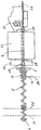
図1は、貯蔵容器(図1には示さず)から消耗分析品を取り出すための本発明による装置の好ましい態様を示しており、機械的経路制御経由での位置依存推力という本発明による概念を実現すると共に、この態様は非常に小型で電池駆動の分析装置への使用に有利なものでもある。前記装置は電気駆動モーター1を備え、該電気駆動モーター1の駆動力はトランスミッション2により駆動輪3に伝達される。円筒形でありらせん状に巻き込まれた移送らせん5の搬送ペグ4が前記駆動輪3に接続されていて、前記駆動輪3と共に回転できるようにされる。前記移送らせん5はその他端が回転ベアリング6に支持されて回転可能となっており、前記駆動により前記移送らせん5の長手方向軸周りに回転する。
【0042】
前記移送らせん5は経路制御の制御要素としての役割を果たし、ピッチの異なる部分を持つ。移送らせん5は主に例えばばね鋼から成っており、この材料から有利に製造される。前記移送らせん5は、前記駆動輪3と前記回転ベアリング6との間の引っ張り又は圧縮負荷は必ずしもかけられなくてよく、また必ずしも操作中にばねの弾性力を用いなくてもよい。場合によっては一定の弾性力は有効であるが、絶対必要なわけではない。多くの適用例において、前記移送らせん5は比較的堅く、わずかに弾性のあるばね鋼で有利に構成することができ、該ばね鋼は可能な限り堅く、すなわち非常に高いばね定数(ばね率)を持つ。
【0043】
プランジャ7は、前記移送らせん5内を長手方向軸線方向に通過している。図1は、前記移送らせん5内へ完全に引き戻された最初の位置にあるときの、前記プランジャ7を示す。貯蔵容器から分析消耗品を取り出すために、前記プランジャ7は矢印8の方向に向けて、前記移送らせん5から押し出される。該移送らせん5の回転運動を前記プランジャ8の直線運動に変換するため、前記プランジャ7は搬送部材9を備える。該搬送部材9は、変位及び該プランジャ7周りの回転を確保できるよう、該プランジャ7に接続されたレセプタクル・ブッシュ10を持ち、かつ該レセプタクル・ブッシュ10に取り付けられた搬送ピン11を持つ。
【0044】
前記レセプタクル・ブッシュ10の外寸法は、その前記移送らせん5を通っての軸方向の変位を可能にするのに十分なくらい小さい。好ましくは、前記搬送ピン11は、前記移送らせん5の長さ方向を横断するように、すなわち、前記プランジャ7の前記推力方向を横断するよう配置される。前記搬送ピン11は、前記プランジャ7と平行に伸びる搬送ガイド12によって案内される。
【0045】
前記移送らせん5が前記駆動により回転状態に置かれると、該移送らせん5の巻き線が前記搬送ピン11に力を与える。この力は、該搬送ピン11を前記プランジャ7の周りに回転させる成分、及び、該搬送ピン11を前記プランジャ7の方向に移動させる成分を持つ。前記搬送ピン11の回転運動は、前記搬送ガイド12によって阻止されるか、あるいは特別な態様においては、前記回転運動は搬送ガイド12により案内され、残りの力成分が前記移送らせん5を介して前記プランジャ7を移送する。
【0046】
上記のことから、前記レセプタクル・ブッシュ10の軸方向寸法は、常に前記巻き線の間で安全に導かれ、中でつかえることがないような大きさであることは好ましい態様となる。前記レセプタクル・ブッシュ10の軸方向の長さは、有利には、移送らせん5の2本の巻き線間の最大距離の少なくとも半分とすべきである。また、前記プランジャ7は、ブッシュ13内を通過して前方に案内されるようにされていれば十分であり、ここでは、前記プランジャ7の後方端の案内は前記移送らせん5によって行われ、かつ、前記レセプタクル・ブッシュ10はその中で軸方向に変位する。他の態様であってもよく、例えば、前記プランジャ7が付加的な位置、例えば該プランジャ7の後方端で支持されてもよい。前記プランジャ7はこの目的で、例えば案内軸芯がその背面で係合する軸方向の窪みを備えていてもよい。
【0047】
前記移送らせん5及び/又は前記プランジャ7の位置的安定性を高めるため、すなわち側方への変形あるいは曲がりを防ぐ又は減らすため、追加の案内要素がさらに備えられていてもよい。この目的で、例えば長さ方向に溝をつけられたブッシュが内側又は外側から前記移送らせん5を支持するようにしてもよい。前記ブッシュに、さらに前記搬送ガイド12の機能を果たさせることもできる。
【0048】
前記搬送ガイド12の形状を定めることで、前記プランジャ7の長手方向軸に対する該プランジャの回転位置を簡単かつ正確に規定しかつ制御することができる。これは例えば、前記プランジャ7の先端に刃14を備えるようなときに特に重要である。なぜなら、それにより、実質的に切断線を構成することなく貯蔵容器の前記フォイルを貫通できるという利点があるからである。正確な移送を保証するためは、前記貯蔵容器から取り出されるべき前記分析消耗品に対して、前記プランジャ7が特定の方向性を持つことは重要である。例として、ストリップ型テストエレメントに対する場合に、その適切な移送を保証するために、前記刃14は前記テストストリップの平面に対してほぼ垂直となるようにするべきである。
【0049】
取り出されるべき前記消耗分析品に対する前記プランジャ7及び/又は刃14の制限された方向性は、前記搬送ガイド12により成し遂げられる。この相対位置は前記移送経路の関数として変化させることもできる。前記搬送ガイド12が直線のときは、前記プランジャ7は前進中に回転しない。もし対照的に、前記搬送ガイド12が軸方向にらせんを成していれば、前記プランジャ7は前記搬送ガイド12によって決まる各位置内で回転する。
【0050】
前記移送らせん5の回転方向が逆向きにされると、前記プランジャ7が動く方向も逆方向となる。前記搬送部材9の形態及び前記移送らせん5のピッチを適宜定めることにより、短い期間、前記プランジャ7の移動を伴うことなく前記移送らせん5を回転させることが起こる。この期間は、前記移送らせん5の巻き線が前記搬送ピン11に再び衝接すると同時に終了し、その後に、前記搬送ピン11の変位が生じる。それにより生じるこのわずかな不感時間は、実際の使用を混乱させることはなく、また、前記搬送ピン11と前記搬送らせん5との間の接合関係を適切なものとすることにより、減らすかあるいはなくすことができる。さらに、前記移送経路の端部で移送工程を終わらせる目的で、前記搬送ピン11が前記移送らせん5の先端又は末端に配置される端部スイッチを操作することもできる。
【0051】
前記移送らせん5はその長さ方向に沿って異なるピッチを持つ。そのために、前記移送らせん5がほぼ一定の速度で回転するときであっても、軸方向位置に応じて、前記プランジャ7によって生ずる推力及び前記プランジャ7の推力速度を変化させることができる。前記移送らせん5の各巻き線が互いに接近している小さいピッチを持つ部分において、前記推力は大きくかつ前記推力速度は遅い。前記移送らせん5のピッチが大きく該移送らせん5の巻き線が互いに大きく隔たっている部分において、前記推力は小さくかつ前記推力速度は速い。
【0052】
その結果、前記駆動モーター1は前記プランジャ7が前進する間、一定のピッチを持つ移送らせん5の場合よりも実質的により均等に負荷がかけられる。これには2つの利点がある。第一に、装置の電池に対してより均等に負荷がかけられるため、ダメージとなる出力ピークは回避でき、より大きなエネルギーが取り出される。加えて、前記駆動モーター1は最適な操作条件での操作のために設計可能となり、結果としてエネルギー効率が上がる。このことはまた、消耗品を取り出すために前記プランジャ7が変位するのに必要とする合計時間を短縮する。
【0053】
結果として前記移送らせん5の多様なピッチは、実質的により均一な態様で前記駆動モーター1に負荷を与えるようにされた経路依存トランスミッション、すなわち、プランジャ7の前進中に当該プランジャ7作用する、前記推力経路に依存して予め決められている当該装置に固有の、負荷変動を補うようにされた経路依存トランスミッションのように作用する。
【0054】
これはもちろん一定の許容範囲内でのみ可能であるが、考慮に入れるべきことは、個々のケースで生ずる負荷変動及び該変動が生ずる位置は、一定の変動のもとにあるということである。また実用化に当たって、例えば残っている電池の容量の減少に起因するオーバータイムを減らすことは前記駆動モーター1の回転速度について許容できることであるし、あるいは、前記プランジャ7が前進する間に小さな残留負荷変動のもとにあることは、前記駆動モーター1について許容できることである。前記負荷変動の大きさ又は該変動の時間全体は、しかしながら、従来装置に比べて、本発明による形状の場合の方が減少しているため、実用化に当たって実質的な利点が得られる。
【0055】
図2は本発明による装置の断面図を示し、前記移送らせん5、前記レセプタクル・ブッシュ10及び、線形搬送ガイド12内の搬送ピン11を描写している。図示した例において、前記搬送ガイド12はブロック内の溝として現される。前記搬送ピン11の位置を決める他の方法は当業者によって容易に実現され得る。
【0056】
図2はまた、消耗分析品が入った17個の室を持つ貯蔵容器を受け入れる受け入れ及び位置決め装置19をも示している。ここにおいて、前記受け入れ装置19は、開口を持つプレート41中に17個の押し抜き開口15を有しており、該プレート41は前記プランジャ7の前方に配置され、該プレート41を通して前記プランジャ7が案内される。案内ピン16が、前記貯蔵容器の中央孔に嵌合するように中央に位置している。
【0057】
駆動装置(図示せず)が前記受け入れ装置19を回転させるために備え付けられ、位置決めは、位置決めディスク17及びスライド式電気接点18によって成し遂げられる。前記貯蔵容器は、自動的に読み取られる評価コードを外側に備えることもできる。
【0058】
関連する測定装置の前記案内ピン16が前記貯蔵容器の中央孔にはめ込まれ、それにより、前記消耗品の取り出しのために該中央孔を正確な位置に固定している。歯のあるつば付き駆動装置を、例えば前記中央孔の端部で前記貯蔵容器内に備え付けることができ、前記貯蔵容器が、分析装置内での回転のために該分析装置内に配置されるときに、対応する形状の協同部品が前記中央孔に係合される。前記貯蔵容器は、前記装置内で、対応する予め決められた位置、すなわち、前記プランジャ7による援助を受けて前記貯蔵容器から消耗品を取り出しかつ測定の準備を容易化できる位置に向けて回転される。
【0059】
前記押し抜き開口15は円形である。前記プランジャ7の軸が好ましくは同様に円形断面を持つからである。しかしながら、このことは、フォイルでシールされた貯蔵容器の取り出し口又は挿入口については必ずしもそうである必要はない。前記開口の領域をできるだけ小さく保つため、これらの開口はしばしば円形ではなく、異なる形とされる。例えば、テストストリップを使っているときは、楕円形又は他の引き伸ばした形が有利であり、該形で縦方向の引き伸ばし方向は前記テストストリップ面の方向である。
【0060】
図3及び4は前記搬送ガイド12内で案内される前記搬送ピン11と前記移送らせん5との協同状態を概略で示す。図5は図1による態様に対応しており、前記移送らせん5が前記搬送ピン11を越えて走るので、前記移送らせん5の回転方向が逆になるとき、該移送らせん5は前記プランジャ7が戻される前にある程度回転させられる必要がある。図4による態様において、前記移送らせん5は、前記搬送ピン11中の開口を通して案内されており、この場合には、回転方向を逆向きにするときのバックラッシュが低減する。異なる態様において、例えば移動可能なスリーブを前記移送らせん5に配置することも可能であり、この場合、該スリーブは前記搬送ピン11に揺動可能なようにヒンジで留められる。
【0061】
図5から図8は、図1の本発明による装置の操作中における様々な段階を描写している。各図は、プランジャ7を備えた前記移送らせん5、案内漏斗20を備えた前記受け入れ装置19、及び、ドラム型貯蔵容器21を示しており、該ドラム型貯蔵容器21からテストエレメント22が室42(図5のみに示す)の外に取り出され、測定装置23内に移される。前記案内漏斗20は、前記プランジャ7を前記貯蔵容器21との関係において正確な位置に案内する。
【0062】
図5において、前記プランジャ7は基本位置24、すなわち前記プランジャ7が前記移送らせん5中に引き戻された位置に位置している。貯蔵容器21は前記受け入れ装置19と係合しており、かつ、位置決め装置を用いることにより、取り出されるべき前記テストエレメント22を収容した前記室42が前記プランジャ7の前方に位置するようにされている。前記テストエレメント22が位置する前記室42の前記挿入口28及び反対側に配置された前記取り出し口29は、フォイルでシールされている。
【0063】
前記移送らせん5が前記駆動装置によって回転状態に置かれ、それにより、前記プランジャ7は前進方向に移動し、フォイル貫通位置25(図6に示す)において、前記挿入口28を覆う前記フォイルを最初に押し抜く。直後に前記テストエレメント22が前記取り出し口29上の前記フォイルを押し裂く。図7に示す前記作業位置26内に前記テストエレメント22をさらに移送すべく、前記プランジャ7がさらに前記貯蔵容器21内に押し込まれる。前記作業位置26で前記テストエレメント22は最初に前記貯蔵容器21から外に移送され、引き続き前記測定装置23内の予め定められた位置に移される。測定を実行するため、前記移送らせん5の回転運動を作業位置26で中断することもできる。
【0064】
図8において、前記テストエレメント22は、測定終了後、排出部位27にある前記プランジャ7からの追加された推力を通して、前記測定装置23から排出される。引き続き、排出部位27にある端部スイッチを励起した後、前記移送らせん5の回転方向を逆向きにすることにより、前記プランジャ7は図5に示す基本位置に戻される。そして、もう一つの端部スイッチが前記基本位置24で前記プランジャ7の戻り運動を止める。
【0065】
フォイル貫通位置25において前記テストエレメント22を前記作業位置26に位置させるとき、及び、該テストエレメントの排出27まで、前記プランジャ7には該テストエレメント22上で増加した推力を生じさせなければならない。対照的に、前記基本位置24から前記フォイル貫通位置25へ、及び、フォイル貫通位置25と前記作業位置26への配置との間の経路に沿って前記プランジャ7を移動するに当たっては、弱い推力だけでたりる。このために、前記移送らせん5のピッチは部分部分で異なっており、前記テストエレメント22を取り出すために前記プランジャ7が前進する間に生ずる前記推力は、該プランジャ7の位置に依存して変化する。前記移送らせん5がほぼ一定の速さで回転するときであっても、前記プランジャ7の位置に依存して異なる推力速度が生ずる。
【0066】
これは図9に示されている。図が示すのは、図5から図8に示す工程における前記プランジャ7の位置sに依存する該プランジャ7の推力30、生じた推力トルク31、及び推力速度32である。前記移送らせん7のピッチは前記推力速度32に比例する。
【0067】
ここにおいて、前記推力30はフォイル貫通位置25と作業位置26の少し前方ですでに増加させられ、その結果、前記推力速度32が減速させられる。前記増加又は減少は、前記作業位置26への入り込み及び排出27の間において、それぞれ、前記フォイルを通して貫入するための技術的要件を適切に満足するために必要とさせる一定の経路に沿って、維持される。
【0068】
図10のブロック図は、位置に依存したプランジャによる推力が純粋な電子的手段を用いてどのように生じうるかを説明している。この目的のため、電池34から駆動モーター1へのエネルギーの流れ33が制御される。前記電池の高い放電を促進するため増幅器35が利用され、該増幅器35は低インピーダンス・モーターと共に使われれば電流を制限でき、もしくはパルス調整作業と共に使われれば電流の制限がある出力を得られる。制御36はタコメーター37、目標値入力部39を持つ調節器38、及び、パルス幅を調節又は線形に整理した出力部40により行われる。この制御はしかしながら、前記駆動モーター1を常には最適作業点に保持することができないために、負荷に依存した機械トランスミッションほど効果的ではない。
【図面の簡単な説明】
【図1】本発明による装置の長さ方向の断面を示す図。
【図2】図1の装置の断面を示す図。
【図3】図1の詳細図を示す図。
【図4】図3に関連する他の形態を示す図。
【図5】基本位置での図1の装置を示す図。
【図6】フォイルを通過するときの図1の装置を示す図。
【図7】テストエレメントを測定位置に移動する図1の装置を示す図。
【図8】前記テストエレメントを排出するときの図1の装置を示す図。
【図9】図5から図8に関連する経路図。
【図10】電子的制御装置を持つ、本発明による装置のブロック図。
【符号の説明】
1 駆動モーター
2 トランスミッション
3 駆動輪
4 搬送ピン
5 移送らせん
6 回転ベアリング
7 プランジャ
8 矢印
9 搬送部材
10 レセプタクル・ブッシュ
11 搬送ピン
12 搬送ガイド
13 ブッシュ
14 刃
15 押し抜き開口
16 案内ピン
17 位置決めディスク
18 スライド式接点
19 受け入れ装置
20 案内漏斗
21 貯蔵容器
22 テストエレメント
23 測定装置
24 基本位置
25 フォイル貫通(位置)
26 作業位置
27 排出部
28 挿入口
29 取り出し口
30 推力
31 推力トルク
32 推力速度
33 エネルギーの流れ
34 電池
35 増幅器
36 制御装置
37 タコメーター
38 調節器
39 目標値
40 出力部
41 隙間の空いたプレート
42 室
s 位置[0001]
BACKGROUND OF THE INVENTION
The present invention relates to an apparatus and corresponding method for removing consumable analytes, in particular test elements, from a storage container with one or more chambers.
[0002]
[Prior art]
In the conventional apparatus and method as described above, each of the chambers contains one or more consumables, each of which has a take-out port for taking out the consumables and a plunger for transferring the consumables to be taken out. And an insertion port located on the opposite side of the extraction port. The take-out port and the insertion port are each sealed with a foil (also called a sealing foil) for storing the consumables. In order to take out the consumables, the plunger is moved by the drive unit, and the consumables are transferred out of the storage container chamber by the plunger.
[0003]
Carrier-bound quick test for use in laboratories performing chemical and biochemical analyzes of solid and liquid samples, and especially for use outside such specialized laboratories. tests) has been established. The carrier binding rapid test is based on the particularly developed dry chemistry and can be carried out by amateurs in a simple and easy way despite the frequently used complex reactions and related reactive reagents. it can.
[0004]
A conventional example of the carrier binding rapid test is a test element for measuring a blood glucose level of a diabetic patient. A strip-shaped diagnostic test element is called a test strip. Conventional examples include urine analysis and one or more feed test strips for various test papers. In addition to the strip-shaped test elements, other types of carrier binding tests are also available, so they are generally referred to as analytical test elements.
[0005]
In the context of the present invention, the analytical test element can be evaluated visually or by a device. Test elements that can be evaluated using the device include, for example, test elements that can be evaluated visually, in particular photometrically, electrochemical sensors and the like. Such analytical test elements and other consumables are contained in storage containers to protect them from damaging surrounding effects such as light, moisture, and mechanical effects, or to preserve them aseptically. The In addition to the test element, for example, a lancet or an element for extracting a sample can be included in the consumption analysis product.
[0006]
Such types of analytical consumables have been described in the prior art and are fully familiar to those skilled in the art in numerous embodiments, so a detailed description thereof is not necessary here. Instead, for example, the following documents are cited: DE-A 19753847.9, EP-A 0138152, EP-A 0812233, EP-A 082234, EP-A 0630609, EP-A 0565970 and WO 97/02487.
[0007]
The analytical consumables are placed in a storage container made of a hard material to protect the analytical consumables from the effects of optical radiation or air moisture, as well as dirt, bacteria, dust and mechanical effects. If the storage container holds a plurality of consumables, these are usually housed in separate chambers, each of which contains one or more consumables. The storage container can also accommodate various types of analytical consumables, such as test elements and lancets, in each chamber.
[0008]
In order to remove the consumable, one of the chambers is opened by breaking the foil sealing the take-out port and the insertion port. Consumables are removed from the room when it is needed in this way without opening another room, so that the consumables contained in the unopened room will continue to be stored safely. Can do.
[0009]
The storage containers and chambers can be formed in different ways as required and often contain a desiccant to prevent moisture. The storage container may comprise a data storage means, such as a readable printable label, a bar code label, or a magnetic strip, by means of which the data storage means provide specific data and optional data relating to the analytical consumables. Can store and read additional information.
[0010]
The analytical consumable can be removed from the storage container manually or preferably using a mechanical device, and the consumable remaining in the unopened chamber in the storage container continues to be protected by a separate sealing foil. Removal of the consumable is accomplished by pushing it out of the chamber using a plunger.
[0011]
Storage containers for analytical consumables and corresponding devices for the removal of analytical consumables have already been described in the prior art and are familiar to those skilled in the art in numerous embodiments. In this context, for example, the following documents are cited: EP-A 0622119, EP-A 0732590, EP-A 073666, US 5498414, US 5510266, US 5720924 and in particular US 5632410 and DE-A 198554316.
[0012]
The storage container is also called a magazine and is usually considered for use in a measuring device, particularly a small measuring device. In order to place the storage container in a measuring device in which consumables are taken out by the plunger from the storage container, suitable means, in particular functional parts of the analytical device, in particular the plunger, are taken out of the consumable. Correspondingly, measures are taken to accurately position the storage container.
[0013]
The removal of the consumables is often automated, for example, to prevent misoperation and to improve the user's ease of use. In this case, the plunger for taking out the consumable is driven by a drive unit including an electric drive motor and, if necessary, a transmission. Examples of conventional manual devices, motor drives and automatic devices for removing analytical consumables from storage containers are described in the above cited references.
[0014]
The storage container to which the present invention pertains has two opposing openings opened with foil, which must be broken when the consumable is removed. The plunger first penetrates the foil covering the insertion opening, enters the reservoir chamber and pushes out the consumable. The foil covering the take-out port is torn outward by the tip of the consumable in the delivery direction, and the consumable is pushed out of the chamber or carried to a working position. An essential characteristic of this transfer procedure is that a relatively large force is required in an area of the transfer path, for example when penetrating the two foils or when placing the test element at a predetermined position on the measuring holder. Is Rukoto. On the other hand, there may be a relatively small thrust in the remaining transfer paths.
[0015]
The choice of foil material and thickness used to seal the opening in the storage chamber is limited by two requirements. On the other hand, the foil must be strong enough to provide sufficient protection and should not constitute a mechanical weak point during handling of the storage container. On the other hand, the foil should not be too strong. This is because the foil must be broken by the plunger or the consumable analyte using the pressure exerted by the plunger thrust.
[0016]
Especially in compact analyzers operating on small batteries, the expendables, in particular the test elements, must be taken out quickly, while performing as many measurements as possible with a single charge of the battery, There is an opposing requirement that the battery consumption associated with removal should be less.
[0017]
In the prior art, the above-mentioned technical problems concerning the force to be generated, the speed with which the consumables are taken out, and the energy requirements are generated by the force generation of the drive motor and the transmission arranged as required. It is solved by a drive unit that always produces constant thrust to. In this case, the thrust is large enough to overcome the load peaks that occur in the transfer path. Whether this is achieved by selecting a more powerful drive motor with greater battery consumption or by selecting a different transmission ratio depends on the particular use. In other words, it depends on which one is more important whether continuous measurement is to be performed continuously or whether battery energy consumption is to be kept low throughout.
[0018]
[Problems to be solved by the invention]
According to the prior art, the drive mechanism is designed to overcome the maximum value of the load thus generated, and it is the extreme of minimum energy consumption and maximum transfer time or maximum energy consumption and minimum transfer time. Optimized between. However, according to the prior art, a practically optimal solution cannot be obtained. This is because the drive is excessive through a long section of the consumables. This is because the drive is formed based on the maximum load that can occur and, depending on the design of the device, it cannot be optimized to meet the optimum requirements for both speed and energy in this range. Because.
[0019]
The object of the present invention is to improve the apparatus as described above for removing a consumable analysis article, in particular a test element, from a storage container, and in particular in the apparatus associated with the apparatus having a very small structure, The object is to improve the method associated with the use of the device so that the requirements regarding the speed of extraction and the requirements for minimizing the energy consumption associated therewith can be met simultaneously.
[0020]
[Means for Solving the Problems]
In order to achieve this object, in the device and the corresponding method, the magnitude of the thrust caused when the plunger performs a thrusting action to remove the consumable is controlled depending on the position of the plunger. The basic idea underlying the present invention employs a plunger drive in which the two conflicting requirements of quick removal and low energy consumption change in a loaded state depending on the thrust path. By doing so, it is optimized at the same time.
[0021]
Within the framework of the present invention, it has been discovered that the difficult requirement of an apparatus for removing a consumable analyte from a storage container can be solved by using a plunger whose thrust varies as a function of the thrust path. It has also been found that the path or position-dependent thrust can be obtained in a simple manner, so that the entire extraction process can be optimized simultaneously with respect to both the speed and energy consumption requirements and has been considered necessary in the past. As such, it doesn't take into account just one requirement or be reluctant to compromise.
The gist of the present invention is as follows.
(1) An apparatus for taking out a consumable from a storage container (21) having one or more chambers (42) containing a consumable analysis product, wherein each chamber (42) takes out the consumable And an insertion port (28) arranged on the opposite side of the removal port (29) for introducing a plunger (7) for transferring the consumables, The mouth (29) and the insertion port (28) are sealed with foil to store the consumables, and the plunger (7) can be moved by a drive unit including an electric drive motor to remove the consumables. In the device, the magnitude of the thrust (30) generated by the plunger (7) during advancement of the plunger (7) for the removal of consumables is controlled based on the position of the plunger (7). DOO, characterized in, the device.
(2) The thrust (30) is controlled based on an extrusion path through which the plunger (7) passes, the extrusion path being determined in relation to a component occupying a fixed position with respect to the device. The device according to (1).
(3) When the plunger (7) penetrates (25) the foil covering the insertion port (28), the consumable article penetrates (25) the foil covering the extraction port (29), At least one operation of placing the taken-out consumables at a predetermined work position (26) or discharging the used consumables from the predetermined work position (26) (27). Device according to (1) or (2), characterized in that in a state the thrust (30) increases.
(4) A method for taking out a consumable from a storage container (21) having one or more chambers (42) containing a consumable analysis product, wherein each chamber (42) takes out the consumable And an insertion port (28) arranged on the opposite side of the removal port (29) for introducing a plunger (7) for transferring the consumables, In the method, the mouth (29) and the insertion port (28) are sealed with a foil to store the consumables, and the plunger (7) is moved by a drive unit including an electric drive motor to remove the consumables. The magnitude of the thrust (30) generated by the plunger (7) during the advancement of the plunger (7) for taking out consumables is controlled based on the position of the plunger (7). That, said method.
[0022]
For example, as the comparative test shows, the conventional drive with optimized energy savings takes 20 seconds to remove the test strip from the drum magazine, and over 500 test strips with a battery-powered measuring device. Can be measured. On the other hand, if the drive is optimized for rapid removal, only 50 test strips can be measured with a single battery charge, assuming the transfer time is about 4 seconds. In contrast, with the device according to the invention, the transfer time is between 4 and 5 seconds, and it is possible to measure more than 500 test strips with a single battery charge.
[0023]
By using the present invention, the goals that those skilled in the art have attempted to achieve over time are achieved. In addition, restrictions on the material and thickness of the foil are relatively unimportant in the device according to the invention, so that many and more economical materials or materials that are better suited for a particular application can be used as the material of the foil. is there.
[0024]
The following features are preferably used individually or in combination with each other in order to obtain particularly good results regarding the speed with which the consumables are taken out and the energy consumption associated therewith, further considering the mechanical requirements and the necessary costs: It is done.
[0025]
A first preferred feature is that the thrust is controlled depending on the thrust path through which the plunger passes. Preferably, the thrust path is defined in relation to an element having a fixed position with respect to the device. This may be, for example, the initial position of the plunger, the final position of the plunger, or the position where one of the foils is present. As an alternative, the absolute position of the plunger can also be measured.
[0026]
In addition, the removal of the consumable analysis product is advantageously improved by increasing the thrust in at least one of the following working states: when the plunger penetrates the foil covering the insertion opening, the When consumables pass through the foil covering the takeout port, when the removed consumables are placed at a predetermined work position, or when used consumables are removed from the predetermined work position .
[0027]
In this regard, the working position is any predetermined limited position where the consumable needs to be assumed for its intended use, for example, a sample location or a position where analytical measurements are performed. Etc. The consumables must be accurately placed at such working positions. To that end, a corresponding guide or contact member is provided prior to the increase in thrust required to transport the consumable. In general, the device according to the invention can obtain the required increased thrust in areas where increased loads occur, for example at the positions described above. On the other hand, the thrust can be lower in other areas along the path of the plunger. Since the increased thrust is supplied only in the area where the plunger requires an increased load, energy consumption can be minimized.
[0028]
In a further preferred aspect, the device is configured in such a way that the speed of the plunger is decelerated in an area where increased thrust occurs and accelerated in an area where reduced thrust occurs. As a result, the total transfer time for taking out the consumables can be optimized while taking into account the corresponding energy consumption.
[0029]
The desired dependence between thrust and thrust path can in principle be realized using pure electronic means, in which the thrust action of the plunger is controlled by the electronic control means of the drive unit. Is done. For this purpose, for example, the driving force or rotational speed of the drive motor may be controlled, or the transmission may be adjusted. Other possible electronic controls include the use of stepping motors, electric commutation motors, current control of the drive motor, control of the pulse width of the drive motor, or similar methods. Electronic control can advantageously obtain a thrust speed independent of the operating voltage. In general, however, such control is associated with the disadvantages of greater structural difficulties and higher costs, and it is usually difficult to maintain the drive motor at an optimized work point.
[0030]
In a preferred feature of the invention, the drive unit can be driven with a substantially constant driving force and / or a substantially constant rotational speed.ElectricalIncludes drive motor. This is to make the use of energy as close as possible as possible by uniformly loading a power source, for example a battery or accumulator, and to operate the drive motor at an efficient operating point.
[0031]
In the present invention, these goals are preferably achieved when the thrust action of the plunger is controlled by mechanical path control, in particular mechanical control with cam or curved path. Mechanical path control has the additional advantage of being simple and economical from a structural point of view, while reducing friction losses. In addition, the transfer position of the plunger along the thrust path, and the thrust or thrust speed are usually required in an electronically controlled solution through cooperation between the mechanical path control and the plunger. Each can be determined depending on the position of the plunger without the need for special distance or position sensors. The cooperative relationship between the mechanical path control and the plunger can connect the position of the plunger and the thrust or thrust speed, respectively.
[0032]
Mechanical path control can be accomplished in a variety of different ways. In a preferred embodiment, the path control may comprise a spirally wound control element that rotates about its longitudinal axis to control the plunger feed.Including electric drive motorIt can be driven by a drive unit and is connected to a conveying member for moving the plunger in the thrust direction while the control element rotates. Thereby saidIncluding electric drive motorThe rotation of the control element produced by the drive unit is converted into a linear movement of the plunger.
[0033]
A particularly simple structural solution is obtained when the longitudinal axis of the control element extends in the direction of the thrust movement of the plunger. The plunger may be arranged parallel and adjacent to the control element, and may penetrate the control element in the axial direction to create a particularly compact structure.
[0034]
The pitch of the control elements in the mechanical path control may be constant along the spiral winding. In this case, the drive torque of the drive unit is controlled to obtain a position-dependent thrust, and the rotational speed of the control element is varied to obtain a position-dependent thrust speed.
[0035]
In a preferred embodiment, the pitch of the control element varies along the spiral winding of the control element in accordance with the desired thrust and position dependence on the plunger. In this case, in a particularly preferred embodiment, the rotational speed of the motor of the drive unit and / or the rotational speed of the control element is substantially constant while the plunger is advanced.
[0036]
The helically wound control element according to the invention can be realized in several different ways. In one advantageous form, the control element may comprise a cylindrical drum controller with a groove on the outer peripheral surface, in which case the conveying member comprises a block that engages the groove. The groove defines a thrust path having desired characteristics. A conventional construction of this type comprises a spindle drive for the drive of the storage and withdrawal unit in a tall compartment storage container, as described in EP-A 0357935. However, if it is used in the present invention, the conventional structure is too large, especially when used in a small analyzer.
[0037]
Therefore, it is a preferred embodiment to realize the control element wound in a spiral shape in the form of a cylindrical and a transfer spiral wound in a spiral, in which the conveying member is in the winding of the transfer spiral. Shaped as engaging transport pins. When the transfer helix rotates, the transport pins are transferred in the axial direction of the transfer helix depending on the pitch and rotational speed of the transfer helix. Since the transport pin is operatively connected to the plunger, the plunger is moved forward or backward depending on the direction of rotation of the transfer helix, and the thrust and thrust speed are determined by the transfer helix. . In this way, a particularly simple structure is realized for the device according to the invention.
[0038]
An analysis device according to the invention for the analysis of a medical sample using a medical consumable, in particular an analysis using a test element, is characterized in that it comprises a device according to the invention for removing an analytical consumable from a storage container. Attached.
[0039]
The device according to the invention is particularly advantageously used in an analytical device operated independently of a power line, for example a battery or a storage battery. In such an apparatus, the present invention functions particularly effectively to solve the problems associated with the limited energy capacity of the battery or power storage element, while the maximum number of analytical consumables can be transferred. In addition, requirements regarding limited power, optimized transfer time for the plunger, or the presence of limited space can be considered and satisfied. And manufacturing cost can also be held down low.
[0040]
DETAILED DESCRIPTION OF THE INVENTION
The following embodiments according to the invention illustrate further advantageous features and features and are described in detail with reference to the drawings.
[0041]
FIG. 1 shows a preferred embodiment of the device according to the invention for removing a consumable analyte from a storage container (not shown in FIG. 1), which illustrates the concept according to the invention of position-dependent thrust via mechanical path control. As realized, this embodiment is also very advantageous for use in a very small, battery-powered analyzer. The apparatus includes an
[0042]
The
[0043]
The
[0044]
The outer dimensions of the
[0045]
When the
[0046]
From the above, it is a preferable aspect that the axial dimension of the
[0047]
In order to increase the positional stability of the
[0048]
By defining the shape of the
[0049]
Limited orientation of the
[0050]
When the rotation direction of the
[0051]
The
[0052]
As a result, the
[0053]
As a result, the various pitches of the
[0054]
This is of course possible only within a certain tolerance, but what should be taken into account is that the load fluctuations occurring in the individual cases and the position where these fluctuations occur are under constant fluctuations. In practical use, for example, it is acceptable to reduce the overtime due to the decrease in remaining battery capacity with respect to the rotational speed of the
[0055]
FIG. 2 shows a cross-sectional view of the device according to the invention, depicting the
[0056]
FIG. 2 also shows a receiving and
[0057]
A drive device (not shown) is provided for rotating the receiving
[0058]
The
[0059]
The punching
[0060]
3 and 4 schematically show the cooperative state of the
[0061]
FIGS. 5 to 8 depict various stages during the operation of the device according to the invention of FIG. Each figure shows the
[0062]
In FIG. 5, the
[0063]
The
[0064]
In FIG. 8, the
[0065]
When the
[0066]
This is illustrated in FIG. The figure shows a
[0067]
Here, the
[0068]
The block diagram of FIG. 10 illustrates how position-dependent plunger thrust can occur using pure electronic means. For this purpose, the
[Brief description of the drawings]
1 shows a longitudinal section of a device according to the invention.
2 shows a cross section of the device of FIG.
FIG. 3 is a detailed view of FIG. 1;
FIG. 4 is a diagram showing another embodiment related to FIG. 3;
5 shows the device of FIG. 1 in the basic position.
6 shows the apparatus of FIG. 1 as it passes through the foil.
7 shows the apparatus of FIG. 1 for moving a test element to a measurement position.
8 shows the apparatus of FIG. 1 when discharging the test element.
9 is a route diagram related to FIGS. 5 to 8. FIG.
FIG. 10 is a block diagram of an apparatus according to the present invention having an electronic control unit.
[Explanation of symbols]
1 Drive motor
2 Transmission
3 Drive wheels
4 Transport pins
5 Transfer spiral
6 Rotating bearing
7 Plunger
8 Arrow
9 Conveying members
10 Receptacle bush
11 Transport pin
12 Transport guide
13 Bush
14 blades
15 Punching opening
16 Guide pin
17 Positioning disc
18 Sliding contacts
19 Accepting device
20 Guide funnel
21 Storage container
22 Test elements
23 Measuring device
24 Basic position
25 Foil penetration (position)
26 Working position
27 Discharge section
28 insertion slot
29 Outlet
30 thrust
31 Thrust torque
32 Thrust speed
33 Energy flow
34 batteries
35 Amplifier
36 Control device
37 Tachometer
38 Regulator
39 Target value
40 Output section
41 Plate with gaps
42 rooms
s position
Claims (4)
消耗品の取り出しのために前記プランジャ(7)の前進中に該プランジャ(7)によって生ずる推力(30)の大きさが、該プランジャ(7)の位置に基づいて制御されることを特徴とする、前記装置。A from a reservoir with one or more chambers housing the consumable analysis article (42) (21) a device for extracting the consumable, wherein each chamber (42), for consumables extraction An outlet (29) and an insertion port (28) disposed on the opposite side of the outlet (29) for introducing the plunger (7) for transferring the consumables are provided, and the outlet (29) ) And the insertion port (28) are sealed with foil to store the consumables, and the plunger (7) can be moved by a drive unit including an electric drive motor to remove the consumables,
The size of the plunger (7) thrust caused by the plunger (7) during advancement of for removal of a consumable (30), characterized in that that are controlled based on the position of the plunger (7) The device.
消耗品の取り出しのために前記プランジャ(7)の前進中に該プランジャ(7)によって生ずる推力(30)の大きさが、該プランジャ(7)の位置に基づいて制御されることを特徴とする、前記方法。A method for retrieving from a storage container having one or more chambers housing the consumable analysis article (42) (21) the consumable, wherein each chamber (42), for consumables extraction An outlet (29) and an insertion port (28) disposed on the opposite side of the outlet (29) for introducing the plunger (7) for transferring the consumables are provided, and the outlet (29) ) And the insertion port (28) are sealed with foil to store the consumables, and the plunger (7) is moved by a drive unit including an electric drive motor to remove the consumables,
The amount of thrust (30) generated by the plunger (7) during the advancement of the plunger (7) for the removal of consumables is controlled based on the position of the plunger (7). , Said method.
Applications Claiming Priority (2)
| Application Number | Priority Date | Filing Date | Title |
|---|---|---|---|
| DE19902601.7 | 1999-01-23 | ||
| DE19902601A DE19902601A1 (en) | 1999-01-23 | 1999-01-23 | Method and device for removing analytical consumables from a storage container |
Publications (3)
| Publication Number | Publication Date |
|---|---|
| JP2000214173A JP2000214173A (en) | 2000-08-04 |
| JP2000214173A5 JP2000214173A5 (en) | 2005-09-15 |
| JP4331847B2 true JP4331847B2 (en) | 2009-09-16 |
Family
ID=7895164
Family Applications (1)
| Application Number | Title | Priority Date | Filing Date |
|---|---|---|---|
| JP2000012901A Expired - Lifetime JP4331847B2 (en) | 1999-01-23 | 2000-01-21 | Method and apparatus for removing a consumable product from a storage container |
Country Status (6)
| Country | Link |
|---|---|
| US (3) | US6475436B1 (en) |
| EP (1) | EP1022565B1 (en) |
| JP (1) | JP4331847B2 (en) |
| AT (1) | ATE363659T1 (en) |
| DE (2) | DE19902601A1 (en) |
| ES (1) | ES2285974T3 (en) |
Families Citing this family (104)
| Publication number | Priority date | Publication date | Assignee | Title |
|---|---|---|---|---|
| US6036924A (en) | 1997-12-04 | 2000-03-14 | Hewlett-Packard Company | Cassette of lancet cartridges for sampling blood |
| US6391005B1 (en) | 1998-03-30 | 2002-05-21 | Agilent Technologies, Inc. | Apparatus and method for penetration with shaft having a sensor for sensing penetration depth |
| AU753745B2 (en) | 1998-04-24 | 2002-10-24 | Roche Diagnostics Gmbh | Storage container for analytical devices |
| DE19902601A1 (en) * | 1999-01-23 | 2000-07-27 | Roche Diagnostics Gmbh | Method and device for removing analytical consumables from a storage container |
| DE10138661A1 (en) | 2000-09-01 | 2002-05-02 | Roche Diagnostics Gmbh | To control the usefulness of test strips, used for the analysis of human/animal body fluids e.g. blood glucose, a strip is measured to give a control reference value to be used in measuring further test strips |
| US8641644B2 (en) | 2000-11-21 | 2014-02-04 | Sanofi-Aventis Deutschland Gmbh | Blood testing apparatus having a rotatable cartridge with multiple lancing elements and testing means |
| EP1404235A4 (en) | 2001-06-12 | 2008-08-20 | Pelikan Technologies Inc | Method and apparatus for lancet launching device integrated onto a blood-sampling cartridge |
| ATE497731T1 (en) | 2001-06-12 | 2011-02-15 | Pelikan Technologies Inc | DEVICE FOR INCREASING THE SUCCESS RATE OF BLOOD YIELD OBTAINED BY A FINGER PICK |
| US9795747B2 (en) | 2010-06-02 | 2017-10-24 | Sanofi-Aventis Deutschland Gmbh | Methods and apparatus for lancet actuation |
| WO2002100252A2 (en) | 2001-06-12 | 2002-12-19 | Pelikan Technologies, Inc. | Blood sampling apparatus and method |
| US7981056B2 (en) | 2002-04-19 | 2011-07-19 | Pelikan Technologies, Inc. | Methods and apparatus for lancet actuation |
| US7025774B2 (en) | 2001-06-12 | 2006-04-11 | Pelikan Technologies, Inc. | Tissue penetration device |
| US9427532B2 (en) | 2001-06-12 | 2016-08-30 | Sanofi-Aventis Deutschland Gmbh | Tissue penetration device |
| DE60234598D1 (en) | 2001-06-12 | 2010-01-14 | Pelikan Technologies Inc | SELF-OPTIMIZING LANZET DEVICE WITH ADAPTANT FOR TEMPORAL FLUCTUATIONS OF SKIN PROPERTIES |
| WO2002100460A2 (en) | 2001-06-12 | 2002-12-19 | Pelikan Technologies, Inc. | Electric lancet actuator |
| US9226699B2 (en) | 2002-04-19 | 2016-01-05 | Sanofi-Aventis Deutschland Gmbh | Body fluid sampling module with a continuous compression tissue interface surface |
| US8337419B2 (en) | 2002-04-19 | 2012-12-25 | Sanofi-Aventis Deutschland Gmbh | Tissue penetration device |
| US7892185B2 (en) | 2002-04-19 | 2011-02-22 | Pelikan Technologies, Inc. | Method and apparatus for body fluid sampling and analyte sensing |
| US7291117B2 (en) | 2002-04-19 | 2007-11-06 | Pelikan Technologies, Inc. | Method and apparatus for penetrating tissue |
| US7491178B2 (en) | 2002-04-19 | 2009-02-17 | Pelikan Technologies, Inc. | Method and apparatus for penetrating tissue |
| US7371247B2 (en) | 2002-04-19 | 2008-05-13 | Pelikan Technologies, Inc | Method and apparatus for penetrating tissue |
| US9314194B2 (en) | 2002-04-19 | 2016-04-19 | Sanofi-Aventis Deutschland Gmbh | Tissue penetration device |
| US8784335B2 (en) | 2002-04-19 | 2014-07-22 | Sanofi-Aventis Deutschland Gmbh | Body fluid sampling device with a capacitive sensor |
| US7976476B2 (en) | 2002-04-19 | 2011-07-12 | Pelikan Technologies, Inc. | Device and method for variable speed lancet |
| US9795334B2 (en) | 2002-04-19 | 2017-10-24 | Sanofi-Aventis Deutschland Gmbh | Method and apparatus for penetrating tissue |
| US7229458B2 (en) | 2002-04-19 | 2007-06-12 | Pelikan Technologies, Inc. | Method and apparatus for penetrating tissue |
| US7297122B2 (en) | 2002-04-19 | 2007-11-20 | Pelikan Technologies, Inc. | Method and apparatus for penetrating tissue |
| WO2003089917A1 (en) * | 2002-04-19 | 2003-10-30 | Matsushita Electric Industrial Co., Ltd. | Biosensor cartridge and biosensor dispensing device |
| US8221334B2 (en) | 2002-04-19 | 2012-07-17 | Sanofi-Aventis Deutschland Gmbh | Method and apparatus for penetrating tissue |
| US7909778B2 (en) | 2002-04-19 | 2011-03-22 | Pelikan Technologies, Inc. | Method and apparatus for penetrating tissue |
| US7175642B2 (en) | 2002-04-19 | 2007-02-13 | Pelikan Technologies, Inc. | Methods and apparatus for lancet actuation |
| US8267870B2 (en) | 2002-04-19 | 2012-09-18 | Sanofi-Aventis Deutschland Gmbh | Method and apparatus for body fluid sampling with hybrid actuation |
| US7892183B2 (en) | 2002-04-19 | 2011-02-22 | Pelikan Technologies, Inc. | Method and apparatus for body fluid sampling and analyte sensing |
| US8579831B2 (en) | 2002-04-19 | 2013-11-12 | Sanofi-Aventis Deutschland Gmbh | Method and apparatus for penetrating tissue |
| US9248267B2 (en) | 2002-04-19 | 2016-02-02 | Sanofi-Aventis Deustchland Gmbh | Tissue penetration device |
| US7708701B2 (en) | 2002-04-19 | 2010-05-04 | Pelikan Technologies, Inc. | Method and apparatus for a multi-use body fluid sampling device |
| US7232451B2 (en) | 2002-04-19 | 2007-06-19 | Pelikan Technologies, Inc. | Method and apparatus for penetrating tissue |
| US8702624B2 (en) | 2006-09-29 | 2014-04-22 | Sanofi-Aventis Deutschland Gmbh | Analyte measurement device with a single shot actuator |
| US7648468B2 (en) | 2002-04-19 | 2010-01-19 | Pelikon Technologies, Inc. | Method and apparatus for penetrating tissue |
| US7547287B2 (en) | 2002-04-19 | 2009-06-16 | Pelikan Technologies, Inc. | Method and apparatus for penetrating tissue |
| US7901362B2 (en) | 2002-04-19 | 2011-03-08 | Pelikan Technologies, Inc. | Method and apparatus for penetrating tissue |
| US8360992B2 (en) | 2002-04-19 | 2013-01-29 | Sanofi-Aventis Deutschland Gmbh | Method and apparatus for penetrating tissue |
| US7674232B2 (en) | 2002-04-19 | 2010-03-09 | Pelikan Technologies, Inc. | Method and apparatus for penetrating tissue |
| US7717863B2 (en) | 2002-04-19 | 2010-05-18 | Pelikan Technologies, Inc. | Method and apparatus for penetrating tissue |
| US7331931B2 (en) | 2002-04-19 | 2008-02-19 | Pelikan Technologies, Inc. | Method and apparatus for penetrating tissue |
| US20060099108A1 (en) * | 2002-12-23 | 2006-05-11 | Hans List | Transport device for transporting test strips in an analysis system |
| US8574895B2 (en) | 2002-12-30 | 2013-11-05 | Sanofi-Aventis Deutschland Gmbh | Method and apparatus using optical techniques to measure analyte levels |
| DE602004028463D1 (en) | 2003-05-30 | 2010-09-16 | Pelikan Technologies Inc | METHOD AND DEVICE FOR INJECTING LIQUID |
| ES2490740T3 (en) | 2003-06-06 | 2014-09-04 | Sanofi-Aventis Deutschland Gmbh | Apparatus for blood fluid sampling and analyte detection |
| WO2006001797A1 (en) | 2004-06-14 | 2006-01-05 | Pelikan Technologies, Inc. | Low pain penetrating |
| DE10338446A1 (en) | 2003-08-21 | 2005-03-31 | Roche Diagnostics Gmbh | Positioning device for a test element |
| WO2005033659A2 (en) | 2003-09-29 | 2005-04-14 | Pelikan Technologies, Inc. | Method and apparatus for an improved sample capture device |
| EP1680014A4 (en) | 2003-10-14 | 2009-01-21 | Pelikan Technologies Inc | Method and apparatus for a variable user interface |
| DE10348283A1 (en) * | 2003-10-17 | 2005-05-12 | Roche Diagnostics Gmbh | Hand-held device for examining a body fluid |
| US7347342B2 (en) * | 2003-10-30 | 2008-03-25 | Elmar Grandy | Container for holding sterile goods and sterile goods dispenser |
| DE10353445B4 (en) | 2003-11-15 | 2017-03-02 | Roche Diabetes Care Gmbh | Dispenser container and storage container for analytical consumables |
| DE10360786B4 (en) | 2003-12-23 | 2005-12-22 | Roche Diagnostics Gmbh | Handheld analyzer |
| DE10361261B4 (en) * | 2003-12-24 | 2006-02-09 | Roche Diagnostics Gmbh | Handheld analyzer |
| US7822454B1 (en) | 2005-01-03 | 2010-10-26 | Pelikan Technologies, Inc. | Fluid sampling device with improved analyte detecting member configuration |
| EP1706026B1 (en) | 2003-12-31 | 2017-03-01 | Sanofi-Aventis Deutschland GmbH | Method and apparatus for improving fluidic flow and sample capture |
| DE102004010529B4 (en) * | 2004-03-04 | 2007-09-06 | Roche Diagnostics Gmbh | Handheld analyzer |
| WO2006011062A2 (en) | 2004-05-20 | 2006-02-02 | Albatros Technologies Gmbh & Co. Kg | Printable hydrogel for biosensors |
| US9775553B2 (en) | 2004-06-03 | 2017-10-03 | Sanofi-Aventis Deutschland Gmbh | Method and apparatus for a fluid sampling device |
| WO2005120365A1 (en) | 2004-06-03 | 2005-12-22 | Pelikan Technologies, Inc. | Method and apparatus for a fluid sampling device |
| DE102004033317A1 (en) * | 2004-07-09 | 2006-02-09 | Roche Diagnostics Gmbh | Analytical test element |
| DE102004036474A1 (en) | 2004-07-28 | 2006-03-23 | Roche Diagnostics Gmbh | Analysis system for analyzing a sample on a test element |
| EP2248589A1 (en) | 2004-12-13 | 2010-11-10 | Bayer Healthcare Llc | Self-contained test sensor |
| DE102004060322A1 (en) | 2004-12-15 | 2006-06-22 | Roche Diagnostics Gmbh | Analysis system with an electrical connection system for a test element |
| JP2006170974A (en) | 2004-12-15 | 2006-06-29 | F Hoffmann-La Roche Ag | Analysis system for analyzing liquid sample on assay element |
| US8652831B2 (en) | 2004-12-30 | 2014-02-18 | Sanofi-Aventis Deutschland Gmbh | Method and apparatus for analyte measurement test time |
| US20060241669A1 (en) * | 2005-04-04 | 2006-10-26 | Stout Jeffrey T | Narrow-profile lancing device |
| EP1712910A1 (en) * | 2005-04-12 | 2006-10-18 | F.Hoffmann-La Roche Ag | Analysis device for analysing a sample fluid using a test element |
| ES2315775T3 (en) | 2005-10-25 | 2009-04-01 | F. Hoffmann-La Roche Ag | ANALYSIS DEVICE FOR THE ANALYSIS OF A SAMPLE IN A TEST ELEMENT. |
| US8940246B2 (en) | 2006-03-13 | 2015-01-27 | Nipro Diagnostics, Inc. | Method and apparatus for coding diagnostic meters |
| US8388905B2 (en) | 2006-03-13 | 2013-03-05 | Nipro Diagnostics, Inc. | Method and apparatus for coding diagnostic meters |
| US8388906B2 (en) | 2006-03-13 | 2013-03-05 | Nipro Diagnostics, Inc. | Apparatus for dispensing test strips |
| US11559810B2 (en) | 2006-03-13 | 2023-01-24 | Trividia Health, Inc. | Method and apparatus for coding diagnostic meters |
| US7597853B2 (en) | 2006-05-09 | 2009-10-06 | Becton, Dickinson And Company | Method and apparatus for dispensing diagnostic test strips |
| US7887757B2 (en) * | 2006-05-09 | 2011-02-15 | Becton, Dickinson And Company | Method and apparatus for dispensing diagnostic test strips |
| US20090312622A1 (en) | 2006-09-28 | 2009-12-17 | Werner Regittnig | Device And Method For Determining A Value Of A Physiological Parameter Of A Body Fluid |
| EP1970711A1 (en) * | 2007-03-16 | 2008-09-17 | Radiometer Medical ApS | Reagent cup device |
| WO2009032760A2 (en) | 2007-08-30 | 2009-03-12 | Pepex Biomedical Llc | Electrochmical sensor and method for manufacturing |
| WO2009051901A2 (en) | 2007-08-30 | 2009-04-23 | Pepex Biomedical, Llc | Electrochemical sensor and method for manufacturing |
| EP2265324B1 (en) | 2008-04-11 | 2015-01-28 | Sanofi-Aventis Deutschland GmbH | Integrated analyte measurement system |
| US8394637B2 (en) | 2008-06-02 | 2013-03-12 | Roche Diagnostics Operations, Inc. | Handheld analyzer for testing a sample |
| US8951377B2 (en) | 2008-11-14 | 2015-02-10 | Pepex Biomedical, Inc. | Manufacturing electrochemical sensor module |
| US8506740B2 (en) | 2008-11-14 | 2013-08-13 | Pepex Biomedical, Llc | Manufacturing electrochemical sensor module |
| US9445755B2 (en) | 2008-11-14 | 2016-09-20 | Pepex Biomedical, Llc | Electrochemical sensor module |
| US8147755B2 (en) | 2008-11-26 | 2012-04-03 | Roche Diagnostics Operations, Inc. | Drum type container for analytical elements |
| US9375169B2 (en) | 2009-01-30 | 2016-06-28 | Sanofi-Aventis Deutschland Gmbh | Cam drive for managing disposable penetrating member actions with a single motor and motor and control system |
| EP2287605A1 (en) | 2009-08-20 | 2011-02-23 | Roche Diagnostics GmbH | Simplified magazining of integrated systems |
| JP2011053110A (en) * | 2009-09-02 | 2011-03-17 | Hitachi High-Technologies Corp | Chemical analyzer |
| EP2322924A1 (en) | 2009-10-15 | 2011-05-18 | F. Hoffmann-La Roche AG | Protection from hydrophobic agents |
| US8965476B2 (en) | 2010-04-16 | 2015-02-24 | Sanofi-Aventis Deutschland Gmbh | Tissue penetration device |
| EP2463030A1 (en) * | 2010-12-08 | 2012-06-13 | F. Hoffmann-La Roche AG | Storage assembly for providing reagent carriers for being processed in an analyzing system |
| KR20140036178A (en) | 2011-05-13 | 2014-03-25 | 베크만 컬터, 인코포레이티드 | Laboratory product transport element and path arrangement |
| WO2012162151A2 (en) | 2011-05-20 | 2012-11-29 | Pepex Biomedical, Inc. | Manufacturing electrochemical sensor modules |
| BR122021026652B1 (en) | 2011-10-17 | 2022-08-23 | F. Hoffmann-La Roche Ag | IN VITRO METHOD TO DIAGNOSE INTERMITTENT ATRIAL FIBRILLATION, USE OF A CARDIAC TROPONIN AND DEVICE TO DIAGNOSE INTERMITTENT ATRIAL FIBRILLATION |
| BR112015012958B1 (en) | 2012-12-03 | 2022-03-15 | Pepex Biomedical, Inc | Sensor module to detect an analyte in a blood sample |
| EP2770064A1 (en) | 2013-02-22 | 2014-08-27 | F. Hoffmann-La Roche AG | Highly efficient production of blood glucose test strips |
| BR112016028536B1 (en) | 2014-06-04 | 2021-11-30 | Pepex Biomedical, Inc | SENSOR COMPRISING A SKIN DRILLING MEMBER AND A BLOOD SAMPLE ANALYSIS ZONE |
| WO2016178899A1 (en) | 2015-05-01 | 2016-11-10 | Abbott Laboratories | Apparatus for removing liquid contents of a container |
| US9798886B2 (en) | 2015-07-08 | 2017-10-24 | International Business Machines Corporation | Bio-medical sensing platform |
| EP3387596A1 (en) | 2015-12-07 | 2018-10-17 | 6 River Systems, Inc. | Warehouse automation systems and methods using a motor-driven cart |
Family Cites Families (40)
| Publication number | Priority date | Publication date | Assignee | Title |
|---|---|---|---|---|
| FR2135984A5 (en) * | 1971-03-01 | 1972-12-22 | Envirotech Corp | |
| JPS5770426A (en) * | 1980-10-21 | 1982-04-30 | Seishin Seiyaku Kk | Automatic sampler |
| DE3314961A1 (en) * | 1983-04-25 | 1984-10-25 | Boehringer Mannheim Gmbh, 6800 Mannheim | ANALYZER FOR PHOTOMETRICALLY DETERMINING A PARAMETER OF A LIQUID |
| SE8305704D0 (en) | 1983-10-18 | 1983-10-18 | Leo Ab | Cuvette |
| US4569828A (en) * | 1984-11-27 | 1986-02-11 | Gakei Electric Works Co., Ltd. | Crystal pulling apparatus for making single crystals of compound semiconductors containing a volatile component |
| JPS62273456A (en) * | 1986-05-21 | 1987-11-27 | Tosoh Corp | Seal breaker for breaking seal foil of test cup used for analyzer |
| JPS6332324A (en) * | 1986-07-26 | 1988-02-12 | Hitachi Ltd | Liquid dispensing device |
| US4872591A (en) * | 1987-11-19 | 1989-10-10 | Konopka Richard O | Medication dispenser |
| US4951512A (en) * | 1988-06-23 | 1990-08-28 | Baxter International Inc. | System for providing access to sealed containers |
| DE3830254A1 (en) * | 1988-09-06 | 1990-03-15 | Man Lager & Systemtechnik | SPINDLE DRIVE |
| JPH0277652A (en) * | 1988-09-14 | 1990-03-16 | Hitachi Ltd | Dividedly pouring device |
| WO1990008307A1 (en) * | 1988-12-29 | 1990-07-26 | Technicon Instruments Corporation | Integrated sampler for closed and open sample containers |
| EP0433436B1 (en) * | 1989-07-07 | 1998-06-10 | Dade Behring Inc. | Assembly for removing waste from closed sample containers |
| JP2886894B2 (en) * | 1989-07-24 | 1999-04-26 | 株式会社日立製作所 | Automatic analyzer |
| DE69117564T2 (en) * | 1990-04-18 | 1996-08-08 | Du Pont | Device for taking samples from open and closed containers |
| CA2072311A1 (en) * | 1991-06-26 | 1992-12-27 | Ronald E. Betts | Integrated circuit hydrated sensor apparatus with electronic wiring substrate with electrochemical sensor storage devic and fluid sample analyte collector and calibration assemblyand multiple use module |
| DE4212315A1 (en) | 1992-04-13 | 1993-10-14 | Boehringer Mannheim Gmbh | Blood lancet device for drawing blood for diagnostic purposes |
| US5332549A (en) * | 1992-07-01 | 1994-07-26 | Pb Diagnostic Systems, Inc. | Assay module transport apparatus for use in an automated analytical instrument |
| DE4310808C2 (en) * | 1993-04-02 | 1995-06-22 | Boehringer Mannheim Gmbh | Liquid dosing system |
| US5271896A (en) * | 1993-04-16 | 1993-12-21 | Eastman Kodak Company | Plunger and driver mechanism for an analyzer |
| DE59410388D1 (en) * | 1993-04-23 | 2004-10-21 | Roche Diagnostics Gmbh | Floppy disk with test elements arranged in a circle |
| DE4320463A1 (en) | 1993-06-21 | 1994-12-22 | Boehringer Mannheim Gmbh | Blood lancet device for drawing blood for diagnostic purposes |
| DE4326931A1 (en) * | 1993-08-11 | 1995-02-16 | Hoechst Ag | Device for removing solid dosage forms from blister packs |
| US5777210A (en) * | 1996-04-25 | 1998-07-07 | Voelker Sensors, Inc. | Oil quality sensor measuring bead volume |
| US5762770A (en) | 1994-02-21 | 1998-06-09 | Boehringer Mannheim Corporation | Electrochemical biosensor test strip |
| US5517867A (en) * | 1994-07-15 | 1996-05-21 | E. I. Du Pont De Nemours And Company | Liquid extraction apparatus |
| US5630986A (en) | 1995-01-13 | 1997-05-20 | Bayer Corporation | Dispensing instrument for fluid monitoring sensors |
| CA2170560C (en) * | 1995-04-17 | 2005-10-25 | Joseph L. Moulton | Means of handling multiple sensors in a glucose monitoring instrument system |
| US5510266A (en) * | 1995-05-05 | 1996-04-23 | Bayer Corporation | Method and apparatus of handling multiple sensors in a glucose monitoring instrument system |
| US6156565A (en) * | 1996-02-21 | 2000-12-05 | Biomerieux, Inc. | Incubation station for test sample cards |
| US6605471B1 (en) * | 1996-05-30 | 2003-08-12 | Radiometer Medical A/S | Method and system for determining at least one parameter of at least one sample of a physiological liquid, a holder and a test device |
| DE19629657A1 (en) | 1996-07-23 | 1998-01-29 | Boehringer Mannheim Gmbh | Volume-independent diagnostic test carrier and method for determining analyte with its aid |
| DE19629656A1 (en) | 1996-07-23 | 1998-01-29 | Boehringer Mannheim Gmbh | Diagnostic test carrier with multilayer test field and method for the determination of analyte with its aid |
| DE19753847A1 (en) | 1997-12-04 | 1999-06-10 | Roche Diagnostics Gmbh | Analytical test element with capillary channel |
| JPH11183484A (en) * | 1997-12-17 | 1999-07-09 | Olympus Optical Co Ltd | Automatic analyzing apparatus |
| AU753745B2 (en) * | 1998-04-24 | 2002-10-24 | Roche Diagnostics Gmbh | Storage container for analytical devices |
| DE19854316A1 (en) | 1998-04-24 | 1999-10-28 | Roche Diagnostics Gmbh | Container for the aids required for rapid analysis tests outside a laboratory |
| JP3771380B2 (en) * | 1998-08-31 | 2006-04-26 | シスメックス株式会社 | Liquid suction device |
| US6145762A (en) * | 1998-10-19 | 2000-11-14 | Cummins Engine Company, Inc. | Variable rate spring for a fuel injector |
| DE19902601A1 (en) * | 1999-01-23 | 2000-07-27 | Roche Diagnostics Gmbh | Method and device for removing analytical consumables from a storage container |
-
1999
- 1999-01-23 DE DE19902601A patent/DE19902601A1/en not_active Withdrawn
-
2000
- 2000-01-18 AT AT00100255T patent/ATE363659T1/en active
- 2000-01-18 DE DE50014353T patent/DE50014353D1/en not_active Expired - Lifetime
- 2000-01-18 ES ES00100255T patent/ES2285974T3/en not_active Expired - Lifetime
- 2000-01-18 EP EP00100255A patent/EP1022565B1/en not_active Expired - Lifetime
- 2000-01-21 JP JP2000012901A patent/JP4331847B2/en not_active Expired - Lifetime
- 2000-01-21 US US09/489,502 patent/US6475436B1/en not_active Expired - Lifetime
-
2002
- 2002-10-01 US US10/262,907 patent/US7211437B2/en not_active Expired - Lifetime
- 2002-10-01 US US10/263,267 patent/US7569187B2/en not_active Expired - Fee Related
Also Published As
| Publication number | Publication date |
|---|---|
| US7569187B2 (en) | 2009-08-04 |
| US20030039584A1 (en) | 2003-02-27 |
| JP2000214173A (en) | 2000-08-04 |
| US7211437B2 (en) | 2007-05-01 |
| EP1022565A3 (en) | 2003-06-18 |
| DE19902601A1 (en) | 2000-07-27 |
| ES2285974T3 (en) | 2007-12-01 |
| US20030027343A1 (en) | 2003-02-06 |
| US6475436B1 (en) | 2002-11-05 |
| EP1022565A2 (en) | 2000-07-26 |
| ATE363659T1 (en) | 2007-06-15 |
| DE50014353D1 (en) | 2007-07-12 |
| EP1022565B1 (en) | 2007-05-30 |
Similar Documents
| Publication | Publication Date | Title |
|---|---|---|
| JP4331847B2 (en) | Method and apparatus for removing a consumable product from a storage container | |
| US7922974B2 (en) | Handheld apparatus for analysis with a conveyance path for test elements | |
| JP2954436B2 (en) | Test piece supply device and analyzer using the same | |
| JP4755663B2 (en) | Analyzer with a replaceable magazine for test elements | |
| US9364172B2 (en) | System for collecting samples and method for collecting a liquid sample | |
| JP4996811B2 (en) | Device for penetrating tissue and method for manufacturing the same | |
| JP4005081B2 (en) | Manual analyzer | |
| US20100198109A1 (en) | Puncturing system and tape cassette | |
| CN101365386A (en) | Lancet integrated test element tape dispenser | |
| US8540647B2 (en) | Lancing device | |
| EP2191773A1 (en) | Strip magazine for hand-held device for analyzing body fluids, and hand-held device | |
| WO2005065828A1 (en) | Hand-held analysis device | |
| JP2007526464A5 (en) | ||
| JP4471425B2 (en) | Sensor supply device | |
| KR101609489B1 (en) | Hand-held analytical device and method for its operation | |
| EP2968060B1 (en) | Test strip grabber | |
| CN220055688U (en) | Test paper storage and transmission device | |
| CN108872623A (en) | A kind of sampling apparatus of automatic clinical chemistry analyzer | |
| CN117342310A (en) | Test paper storage and transmission device | |
| JP5828796B2 (en) | Device for penetrating tissue with a penetrating member driver |
Legal Events
| Date | Code | Title | Description |
|---|---|---|---|
| A521 | Request for written amendment filed |
Free format text: JAPANESE INTERMEDIATE CODE: A523 Effective date: 20050331 |
|
| A621 | Written request for application examination |
Free format text: JAPANESE INTERMEDIATE CODE: A621 Effective date: 20050331 |
|
| A977 | Report on retrieval |
Free format text: JAPANESE INTERMEDIATE CODE: A971007 Effective date: 20051124 |
|
| A131 | Notification of reasons for refusal |
Free format text: JAPANESE INTERMEDIATE CODE: A131 Effective date: 20060214 |
|
| A02 | Decision of refusal |
Free format text: JAPANESE INTERMEDIATE CODE: A02 Effective date: 20070109 |
|
| A521 | Request for written amendment filed |
Free format text: JAPANESE INTERMEDIATE CODE: A523 Effective date: 20090421 |
|
| A01 | Written decision to grant a patent or to grant a registration (utility model) |
Free format text: JAPANESE INTERMEDIATE CODE: A01 |
|
| A61 | First payment of annual fees (during grant procedure) |
Free format text: JAPANESE INTERMEDIATE CODE: A61 Effective date: 20090619 |
|
| R150 | Certificate of patent or registration of utility model |
Ref document number: 4331847 Country of ref document: JP Free format text: JAPANESE INTERMEDIATE CODE: R150 Free format text: JAPANESE INTERMEDIATE CODE: R150 |
|
| FPAY | Renewal fee payment (event date is renewal date of database) |
Free format text: PAYMENT UNTIL: 20120626 Year of fee payment: 3 |
|
| FPAY | Renewal fee payment (event date is renewal date of database) |
Free format text: PAYMENT UNTIL: 20120626 Year of fee payment: 3 |
|
| FPAY | Renewal fee payment (event date is renewal date of database) |
Free format text: PAYMENT UNTIL: 20130626 Year of fee payment: 4 |
|
| R250 | Receipt of annual fees |
Free format text: JAPANESE INTERMEDIATE CODE: R250 |
|
| R250 | Receipt of annual fees |
Free format text: JAPANESE INTERMEDIATE CODE: R250 |
|
| R250 | Receipt of annual fees |
Free format text: JAPANESE INTERMEDIATE CODE: R250 |
|
| R250 | Receipt of annual fees |
Free format text: JAPANESE INTERMEDIATE CODE: R250 |
|
| R250 | Receipt of annual fees |
Free format text: JAPANESE INTERMEDIATE CODE: R250 |
|
| R250 | Receipt of annual fees |
Free format text: JAPANESE INTERMEDIATE CODE: R250 |
|
| R250 | Receipt of annual fees |
Free format text: JAPANESE INTERMEDIATE CODE: R250 |
|
| R250 | Receipt of annual fees |
Free format text: JAPANESE INTERMEDIATE CODE: R250 |
|
| EXPY | Cancellation because of completion of term |