JP4323443B2 - Peeling apparatus and peeling method - Google Patents
Peeling apparatus and peeling method Download PDFInfo
- Publication number
- JP4323443B2 JP4323443B2 JP2005052388A JP2005052388A JP4323443B2 JP 4323443 B2 JP4323443 B2 JP 4323443B2 JP 2005052388 A JP2005052388 A JP 2005052388A JP 2005052388 A JP2005052388 A JP 2005052388A JP 4323443 B2 JP4323443 B2 JP 4323443B2
- Authority
- JP
- Japan
- Prior art keywords
- peeling
- film
- tape
- end side
- peeled
- Prior art date
- Legal status (The legal status is an assumption and is not a legal conclusion. Google has not performed a legal analysis and makes no representation as to the accuracy of the status listed.)
- Expired - Fee Related
Links
- 238000000034 method Methods 0.000 title claims description 19
- 238000004804 winding Methods 0.000 claims description 15
- 230000001681 protective effect Effects 0.000 description 4
- 239000011347 resin Substances 0.000 description 4
- 229920005989 resin Polymers 0.000 description 4
- 239000002699 waste material Substances 0.000 description 3
- 239000000853 adhesive Substances 0.000 description 1
- 230000001070 adhesive effect Effects 0.000 description 1
- 238000007796 conventional method Methods 0.000 description 1
- 238000012986 modification Methods 0.000 description 1
- 230000004048 modification Effects 0.000 description 1
- 230000003287 optical effect Effects 0.000 description 1
- 230000001105 regulatory effect Effects 0.000 description 1
Images


Classifications
-
- B—PERFORMING OPERATIONS; TRANSPORTING
- B29—WORKING OF PLASTICS; WORKING OF SUBSTANCES IN A PLASTIC STATE IN GENERAL
- B29C—SHAPING OR JOINING OF PLASTICS; SHAPING OF MATERIAL IN A PLASTIC STATE, NOT OTHERWISE PROVIDED FOR; AFTER-TREATMENT OF THE SHAPED PRODUCTS, e.g. REPAIRING
- B29C63/00—Lining or sheathing, i.e. applying preformed layers or sheathings of plastics; Apparatus therefor
- B29C63/0004—Component parts, details or accessories; Auxiliary operations
- B29C63/0013—Removing old coatings
-
- Y—GENERAL TAGGING OF NEW TECHNOLOGICAL DEVELOPMENTS; GENERAL TAGGING OF CROSS-SECTIONAL TECHNOLOGIES SPANNING OVER SEVERAL SECTIONS OF THE IPC; TECHNICAL SUBJECTS COVERED BY FORMER USPC CROSS-REFERENCE ART COLLECTIONS [XRACs] AND DIGESTS
- Y10—TECHNICAL SUBJECTS COVERED BY FORMER USPC
- Y10T—TECHNICAL SUBJECTS COVERED BY FORMER US CLASSIFICATION
- Y10T156/00—Adhesive bonding and miscellaneous chemical manufacture
- Y10T156/11—Methods of delaminating, per se; i.e., separating at bonding face
- Y10T156/1168—Gripping and pulling work apart during delaminating
- Y10T156/1174—Using roller for delamination [e.g., roller pairs operating at differing speeds or directions, etc.]
-
- Y—GENERAL TAGGING OF NEW TECHNOLOGICAL DEVELOPMENTS; GENERAL TAGGING OF CROSS-SECTIONAL TECHNOLOGIES SPANNING OVER SEVERAL SECTIONS OF THE IPC; TECHNICAL SUBJECTS COVERED BY FORMER USPC CROSS-REFERENCE ART COLLECTIONS [XRACs] AND DIGESTS
- Y10—TECHNICAL SUBJECTS COVERED BY FORMER USPC
- Y10T—TECHNICAL SUBJECTS COVERED BY FORMER US CLASSIFICATION
- Y10T156/00—Adhesive bonding and miscellaneous chemical manufacture
- Y10T156/19—Delaminating means
- Y10T156/195—Delaminating roller means
- Y10T156/1956—Roller pair delaminating means
-
- Y—GENERAL TAGGING OF NEW TECHNOLOGICAL DEVELOPMENTS; GENERAL TAGGING OF CROSS-SECTIONAL TECHNOLOGIES SPANNING OVER SEVERAL SECTIONS OF THE IPC; TECHNICAL SUBJECTS COVERED BY FORMER USPC CROSS-REFERENCE ART COLLECTIONS [XRACs] AND DIGESTS
- Y10—TECHNICAL SUBJECTS COVERED BY FORMER USPC
- Y10T—TECHNICAL SUBJECTS COVERED BY FORMER US CLASSIFICATION
- Y10T156/00—Adhesive bonding and miscellaneous chemical manufacture
- Y10T156/19—Delaminating means
- Y10T156/1978—Delaminating bending means
- Y10T156/1983—Poking delaminating means
Landscapes
- Engineering & Computer Science (AREA)
- Manufacturing & Machinery (AREA)
- Folding Of Thin Sheet-Like Materials, Special Discharging Devices, And Others (AREA)
- Control And Other Processes For Unpacking Of Materials (AREA)
- Processing And Handling Of Plastics And Other Materials For Molding In General (AREA)
Description
本発明は、剥離装置及び剥離方法に係り、更に詳しくは、フィルムの剥離に必要な剥離用テープの無駄を省くことができる剥離装置及び剥離方法に関する。 The present invention relates to a peeling apparatus and a peeling method, and more particularly, to a peeling apparatus and a peeling method that can eliminate waste of a peeling tape necessary for peeling a film.
従来より、板状の剥離対象物の表面に貼付されたフィルムを剥離する方法として、例えば、特許文献1に開示されるタイプの方法が知られている。同文献では、前記フィルムに対し、ローラを介して剥離用テープを接着して巻き取ることで剥離対象物からフィルムを剥離するようになっている。ここで、前記ローラは、フィルムの対角線方向に沿って移動し、当該対角線に沿ってフィルムと剥離用テープとが接着することとなる。 Conventionally, for example, a method of the type disclosed in Patent Document 1 is known as a method of peeling a film attached to the surface of a plate-like peeling target. In this document, the film is peeled off from the object to be peeled by adhering and winding the peeling tape to the film via a roller. Here, the roller moves along the diagonal direction of the film, and the film and the peeling tape adhere to each other along the diagonal line.
しかしながら、このような剥離方法において、一枚のフィルムを剥離するために必要な剥離用テープの長さは、当該フィルムの対角線長さと略同一になる。従って、剥離対象物が複数枚になると、当該枚数に前記対角線長さを乗じた長さの剥離用テープが必要となり、剥離対象物の枚数が増大した際に用いられる剥離用テープ長さが極めて長尺化するという不都合がある。この結果、剥離用テープを供給するロールの交換回数が多くなり、当該交換に要する労力や時間が甚大になるうえ、資源を無駄に消費するという不都合を招来する。 However, in such a peeling method, the length of the peeling tape necessary for peeling a single film is substantially the same as the diagonal length of the film. Therefore, when there are a plurality of objects to be peeled, a stripping tape having a length obtained by multiplying the number of the strips by the diagonal length is necessary, and the length of the stripping tape used when the number of the stripping objects increases is extremely large. There is an inconvenience of lengthening. As a result, the number of times of replacing the roll for supplying the peeling tape is increased, and labor and time required for the replacement are increased, and inconveniences such as wasteful consumption of resources are caused.
[発明の目的]
本発明は、このような不都合に着目して案出されたものであり、その目的は、フィルムに接着する剥離用テープの無駄を省くことができる剥離装置及び剥離方法を提供することにある。
[Object of invention]
The present invention has been devised by paying attention to such inconveniences, and an object of the present invention is to provide a peeling apparatus and a peeling method that can eliminate waste of a peeling tape that adheres to a film.
前記目的を達成するため、本発明は、フィルムが貼付された剥離対象物を支持する剥離用テーブルと、この剥離用テーブルに相対配置される剥離ユニットとを備え、当該剥離ユニットから繰り出される剥離用テープを前記フィルムに接着して送出することで、複数の剥離対象物の各フィルムを順次剥離可能とした剥離装置において、
前記剥離ユニットは、剥離用テープの供給部と、剥離用テープの巻取部と、これら供給部と巻取部との間の剥離用テープに対して相対移動可能な剥離ヘッドとを備え、
前記剥離ヘッドは、フィルムの端部領域に剥離用テープを接着した後、当該フィルムが直前に剥離された別のフィルムに重なるように剥離用テープと相対移動してフィルムを送出可能に設けられる、という構成を採っている。
In order to achieve the above-mentioned object, the present invention comprises a peeling table that supports a peeling object to which a film is attached, and a peeling unit that is disposed relative to the peeling table, and for peeling that is fed from the peeling unit. In a peeling device that can peel each film of a plurality of peeling objects sequentially by bonding and feeding the tape to the film,
The peeling unit includes a peeling tape supply unit, a peeling tape winding unit, and a peeling head movable relative to the peeling tape between the supply unit and the winding unit,
The peeling head is provided so that the film can be fed by moving relative to the peeling tape so that the film overlaps another film peeled immediately before, after the peeling tape is adhered to the end region of the film. The structure is adopted.
本発明において、前記剥離ヘッドは、フィルムの剥離時に、フィルムの一端側から他端側に向かって移動しながら剥離用テープを送出する一方、フィルムの剥離前に、直前に剥離された別のフィルムの他端側から一端側に移動し、その近傍の剥離用テープをフィルムの一端側に接着可能に設けられる、という構成を採ることが好ましい。 In the present invention, at the time of peeling of the film, the peeling head sends out a peeling tape while moving from one end side to the other end side of the film, while another film peeled immediately before peeling of the film. It is preferable to adopt a configuration in which the film is moved from the other end side to the one end side and a peeling tape in the vicinity thereof is provided on the one end side of the film so as to be able to be bonded.
また、本発明は、複数の剥離対象物に貼付された各フィルムに、剥離用テープを接着して前記各フィルムを順次剥離する剥離方法において、
前記フィルムの端部領域に剥離ヘッドを用いて剥離用テープを接着した後に、
そのフィルムの直前に剥離されて剥離用テープに接着された別のフィルムに重なるように前記剥離ヘッドと剥離対象物とを相対移動させて剥離用テープを送出することにより、フィルムを剥離対象物から剥離する、という方法を採っている。
Further, the present invention is a peeling method in which each film attached to a plurality of peeling objects is adhered to a peeling tape and the respective films are sequentially peeled,
After adhering the peeling tape to the edge region of the film using a peeling head,
The film is removed from the object to be peeled by moving the peeling head and the object to be peeled relative to each other so as to overlap another film peeled immediately before the film and adhered to the film for peeling. The method of peeling is used.
前記剥離方法は、前記フィルムの剥離時に、剥離ヘッドがフィルムの一端側から他端側に向かって移動することで剥離用テープを送出する一方、
前記フィルムの剥離前に、直前に剥離された別のフィルムの他端側から一端側に剥離ヘッドが移動し、
次いで、剥離対象物から未剥離のフィルム一端側に、剥離ヘッドを用いて前記別のフィルムの一端側近傍の剥離用テープを接着する、という方法を採ることが好ましい。
While the peeling method, when peeling the film, while the peeling head moves from one end side of the film toward the other end side, the peeling tape is sent out,
Before peeling of the film, the peeling head moves from one end side to the other end side of another film peeled immediately before,
Next, it is preferable to adopt a method in which a peeling tape in the vicinity of one end side of the other film is bonded to one end side of the film that has not been peeled from the peeling target using a peeling head.
本発明によれば、剥離されるフィルムは、剥離用テープに接着される領域と直前に剥離された別のフィルムに重なる領域と有することとなり、当該重なる領域は剥離用テープに非接着としつつ剥離を行うことが可能となる。従って、従来タイプに比べ、前記重なる領域の長さ分剥離用テープを短くすることができる。これにより、剥離用テープにおける単位長さ当たりの剥離可能なフィルム枚数が増大し、剥離対象物を多数枚としても、剥離用テープを供給するロールの交換回数を少なくすることが可能となる。 According to the present invention, the film to be peeled has a region to be bonded to the peeling tape and a region to be overlapped with another film that has been peeled immediately before, and the overlapping region is peeled while being non-adhered to the peeling tape. Can be performed. Therefore, as compared with the conventional type, the peeling tape can be shortened by the length of the overlapping region. As a result, the number of peelable films per unit length in the peeling tape is increased, and the number of replacements of the roll for supplying the peeling tape can be reduced even when the number of peeling objects is large.
また、直前に剥離された別のフィルムの一端側近傍の剥離用テープを、未剥離のフィルム一端側に接着するので、剥離用テープをスポット的に接着することが可能となる。これにより、剥離用テープの無駄を省くことを簡単に達成することができる。 Moreover, since the peeling tape in the vicinity of one end side of another film peeled off immediately before is bonded to the one end side of the unpeeled film, the peeling tape can be spot-bonded. As a result, it is possible to easily achieve the waste of the peeling tape.
以下、本発明の実施の形態について図面を参照しながら説明する。 Hereinafter, embodiments of the present invention will be described with reference to the drawings.
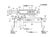
図1には、本実施形態に係る剥離装置の概略正面図が示されている。この図において、剥離装置10は、剥離対象物Dを支持する剥離用テーブル11と、この剥離用テーブル11の下部に相対配置された剥離ユニット12とを備えて構成されている。ここで、剥離対象物Dは、特に限定されるものではないが、DVD等の光ディスクからなり、その支持面の反対側(開放面)には、情報を記憶するピットが形成される樹脂層Jと、それを保護する保護用のフィルムFが貼付されている。
FIG. 1 shows a schematic front view of the peeling apparatus according to the present embodiment. In this figure, the
前記剥離用テーブル11は、図1中下面側に多数の吸着孔を形成して剥離対象物Dを吸着支持可能に設けられている。剥離用テーブル11は、同図中左右両端側で軸部材14を介してインデックステーブル15に支持され、図示しない回転機構によって図中矢印R1方向に回転して前記吸着孔を設けた面を上向き及び下向きに向けることができるようになっている。インデックステーブル15は、回転軸16を中心として図中矢印R2方向に所定角度づつ回転可能に設けられている。ここで、剥離用テーブル11は、図1では一つしか表されていないが、インデックステーブル15には略同一構造のものが前記矢印R2方向に沿って複数設けられ、インデックステーブル15が所定角度回転し、各作業が行われる。図1は、樹脂層Jと、それを保護する保護用のフィルムFとが貼り付けられた剥離対象物Dから、当該保護用のフィルムFを剥離する工程を示す。なお、剥離用テーブル11において、前記吸着孔を設けることに代えて、多孔質部材を配置して剥離対象物Dを吸着支持できるように構成することもできる。
The peeling table 11 is provided so that a large number of suction holes are formed on the lower surface side in FIG. The peeling table 11 is supported by the index table 15 via the
前記剥離ユニット12は、剥離用テーブル11に支持された剥離対象物Dから前記フィルムFを剥離するものである。この剥離ユニット12は、剥離用テーブル11の下方に位置して剥離用テープPTの供給部を構成する支持ロール20と、剥離用テープPTの巻取部を構成する巻取ロール21と、剥離用テープPTをフィルムFに接着して当該フィルムFを剥離する剥離ヘッド22と、この剥離ヘッド22を剥離対象物Dの面方向(図1中左右方向)に沿って移動させるスライダ24とを備えて構成されている。前記支持ロール20及び巻取ロール21は、それぞれモータ(図示省略)の出力軸に連結され、巻取ロール21用のモータは剥離用テープPTの巻取方向に回転駆動する一方、支持ロール20用のモータは、剥離用テープPTの繰出方向とは逆方向に回転力を付与して剥離用テープPTに小さなテンションを与えることができるようになっている。支持ロール20と剥離ヘッド22との間には、第1のガイドロール28が設けられている一方、巻取ロール21と剥離ヘッド22との間には、第2のガイドロール29が設けられている。第1及び第2のガイドロール28,29には、ブレーキ手段を構成するシリンダ31,32がそれぞれ併設されている。各シリンダ31,32のロッドの先端側には圧接体31A,32Aがそれぞれ設けられ、当該圧接体31A,32Aとガイドロール28,29との間の剥離用テープPTに挟持力を付与できるようになっている。
The said
前記剥離ヘッド22は、前記スライダ24に支持されるヘッド本体34と、このヘッド本体34に装着されたシリンダ35と、このシリンダ35におけるロッドの先端側に取り付けられるとともに、シリンダ35を介して剥離用テーブル11に対して離間接近する方向に昇降可能となる第1のロール37と、この第1のロール37と前記第1のガイドロール28との間に設けられた第2のロール38と、第1のロール37と前記第2のガイドロール29との間に設けられた第3のロール39とを備えて構成されている。第1ないし第3のロール37〜39は、それらの間で剥離用テープPTを送出し、この送出により剥離用テープPTと剥離ヘッド22とが相対移動可能となる。第1のロール37は、剥離用テープPTをフィルムFの下面に所定の押圧力を付与して接着させる(図2参照)。第2及び第3のロール38,39は、それらの回転軸がスロット穴41,42にそれぞれ挿通されている。第2及び第3のロール38,39は、図示しないばね等の付勢手段若しくは自重により、回転軸が無負荷状態でスロット穴41,42の下限位置に位置するように付勢されている。
The
なお、前述した回転軸16、支持ロール20、巻取ロール21、スライダ24及びシリンダ31,32は図示しないフレームを介して所定位置に支持されている。
The rotating
次に、本実施形態に係る剥離方法について説明する。 Next, the peeling method according to the present embodiment will be described.
ここでは、図1に示されるように、剥離用テーブル11に支持され、その支持面の反対側に樹脂層Jと、それを保護する保護用のフィルムFが貼付された剥離対象物D(同図中二点鎖線参照)を剥離用テーブル11に載置し、吸着支持した後、図示しない回転機構によって当該剥離用テーブル11を矢印R1方向に回転し、剥離対象物Dを同図中下向きに配置する。剥離用テープPTは、支持ロール20と巻取ロール21との間で所定経路に掛け回される一方、第2のガイドロール29においてシリンダ32により剥離用テープPTが挟持され、巻取リール21側への剥離用テープPTの移動を規制している。また、剥離ヘッド22は、第1のロール37がフィルムFの一端側(同図中左端側)の略直下に位置するように設定されている。
Here, as shown in FIG. 1, a peeling object D (same as the peeling object 11) is supported by a peeling table 11 and a resin layer J and a protective film F for protecting it are affixed to the opposite side of the supporting surface. (Refer to the two-dot chain line in the figure) is placed on the peeling table 11 and sucked and supported, and then the peeling table 11 is rotated in the direction of the arrow R1 by a rotation mechanism (not shown) so that the peeling object D is directed downward in the figure. Deploy. The release tape PT is wound around a predetermined path between the
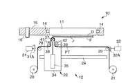
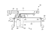
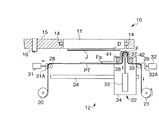
最初の剥離対象物DにおけるフィルムFの剥離は、先ず、図2に示されるように、シリンダ35を介して第1のロール37を上昇させることによって支持ロール20から剥離用テープPTが繰り出される。これにより、当該剥離用テープPTが部分的に下向きU字状に回行され、その上側部分を第1のロール37を介してフィルムFの一端側領域に押圧しながら接着する。この状態で、支持ロール20用のモータ(図示省略)により、剥離用テープPTの繰出方向とは反対の方向に小さな力で当該剥離用テープPTにテンションを付与する。その後、第1のガイドロール28においてシリンダ31により剥離用テープPTを挟持する(図3参照)。そして、スライダ24を介して剥離ヘッド22を図3中右方向に移動することにより、第1のロール37がフィルムFの一端側から他端側(図3中左端側から右端側)に転動するとともに、第1ないし第3のロール37〜39において剥離用テープPTが送出され、フィルムFが剥離用テープPTに接着されながら剥離される(図4参照)。フィルムFが剥離対象物Dから完全に剥離した後、剥離ヘッド22の移動を停止し、シリンダ32と第2のガイドロール29とによる剥離用テープPTの挟持を解除し、巻取ロール21により剥離用テープPTを巻き取りつつ第1のロール37を下降し、第1のガイドロール28と巻取ロール21の間の剥離用テープPTが弛まないように略水平に保つ(図5参照)。そして、前記インデックステーブル15が図5中矢印R3方向に回転し、別の剥離対象物Dを吸着支持した剥離用テーブル11が剥離ヘッド22の上方にセットされる(図6参照)。この状態で、第2のガイドロール29とシリンダ32とにより剥離用テープPTを挟持した後、剥離用テープPTに接着されたフィルムFの一端側方向すなわち図5中左方向に剥離ヘッド22を移動し、剥離用テーブル11に吸着支持された剥離対象物DにおけるフィルムFの一端側(同図中左端側)略直下に第1のロール37をセットする。
For peeling of the film F from the first peeling object D, first, as shown in FIG. 2, the peeling tape PT is fed out from the
この状態から、二枚目の剥離対象物DのフィルムFの剥離が開始される。この剥離は、フィルムFと剥離用テープPTとの接着領域が異なる点を除き、前述した最初のフィルムFの剥離と略同様の手順によって行われる。すなわち、第1のガイドロール28における剥離用テープPTの挟持を解除した後、第1のロール37を上昇して剥離用テープPTを未剥離のフィルムF(以下において、符号Faとする)の一端側領域に押圧しながら接着する(図7参照)。これにより、当該一端側領域と、直前に剥離されたフィルムFの一端側(図7中左側)の近傍領域における剥離用テープPTとが接着される。この状態で、第1のガイドロール28とシリンダ31とにより剥離用テープPTを挟持した後、剥離ヘッド22を図7中右方向に移動し、第1ないし第3のロール37〜39において剥離用テープPTを送出する。この送出により、図8及び図9に示されるように、前記フィルムFaの一端側領域が剥離用テープPTに接着された後、前記フィルムFの一端側領域と前記フィルムFaの他端側領域とが重なりながら当該フィルムFaが完全に剥離される。その後、第2のガイドロール29における剥離用テープPTの挟持を解除した後、巻取ロール21により剥離用テープPTを巻き取りつつ第1のロール37を下降し、剥離用テープPTを略水平とする(図10参照)とともに、前記インデックステーブル15が回転して更に別の剥離対象物Dを吸着する剥離用テーブル11を剥離ヘッド22の上方にセットする(図11参照)。そして、第1及び第2のガイドロール28,29においてシリンダ31,32により剥離用テープPTを挟持した後、図中左方向に剥離ヘッド22を移動する。
From this state, the peeling of the film F of the second peeling target D is started. This peeling is performed according to a procedure substantially similar to the peeling of the first film F described above, except that the adhesion region between the film F and the peeling tape PT is different. That is, after releasing the holding of the peeling tape PT in the
図11の状態において、三枚目の剥離対象物DのフィルムF(図11にFbと示す)を剥離するための準備状態となり、この状態から、二枚目のフィルムFa剥離と同様にして三枚目以降のフィルムFbの剥離を行うことができる(図12参照)。これにより、多数枚の剥離対象物Dの各フィルムFを一本の剥離用テープPTにより順次剥離して巻取リール21に巻き取ることが可能となる。
なお、前述のフィルムFの剥離において、第2及び第3のロール38,39は、剥離用テープPT及びこれに接着されたフィルムFの厚みに応じて上方に移動しつつ、第1のロール37の左右両側の剥離用テープPTを下方に向かって押圧するようになっている。
In the state of FIG. 11, a preparation state for peeling the film F (denoted as Fb in FIG. 11) of the third peeling target D is entered. The film Fb after the 1st sheet | seat can be peeled (refer FIG. 12). As a result, the films F of the large number of objects to be peeled D can be sequentially peeled off by the single peeling tape PT and wound on the take-
In the above-described peeling of the film F, the second and
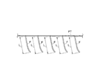
従って、このような実施形態によれば、複数枚の剥離対象物Dの各フィルムFが、その直前に剥離されたフィルムFに重なりながら剥離されるので、仮に、巻取リール21に巻き取られた剥離用テープPTを略水平に向けた場合、図13に示される状態とすることができる。すなわち、同図中のフィルム長さLが各フィルムF同士の重なる領域となり、当該長さLに剥離したフィルムFの枚数を乗じた長さ分、従来方法に比べて剥離用テープPTの無駄を省くことが可能となる。
Therefore, according to such an embodiment, each film F of the plurality of objects to be peeled D is peeled while being overlapped with the film F peeled immediately before, so that the film F is temporarily wound around the take-
本発明を実施するための最良の構成、方法などは、以上の記載で開示されているが、本発明は、これに限定されるものではない。
すなわち、本発明は、主に特定の実施の形態に関して特に図示し、且つ、説明されているが、本発明の技術的思想及び目的の範囲から逸脱することなく、以上に述べた実施の形態に対し、形状、数量、その他の詳細な構成において、当業者が様々な変形を加えることができるものである。
Although the best configuration, method and the like for carrying out the present invention have been disclosed in the above description, the present invention is not limited to this.
That is, the invention has been illustrated and described with particular reference to particular embodiments, but it should be understood that the above-described embodiments are not deviated from the technical idea and scope of the invention. On the other hand, various modifications can be made by those skilled in the art in shape, quantity, and other detailed configurations.
例えば、前記実施形態では、フィルムFの剥離時に、剥離用テーブル11を移動させることなく剥離用ヘッド22を移動するように設けられているが、剥離用ヘッド22に対して剥離用テーブル11を移動させ、当該剥離用ヘッド22と剥離用テープPTとを相対移動させて当該剥離用テープPTを送出可能に設けてもよい。
また、第1及び第2のガイドロール28,29とシリンダ31,32とにより剥離用テープPTの送出を規制可能としたが、これらは、前述と同様の作用を奏する限りにおいて種々の設計変更が可能である。
更に、第1のロール37にヒータを組み込むとともに、剥離用テープPTを感熱性接着剤とし、第1のロール37により剥離用テープPTを加熱しながらフィルムFと接着させる構成としてもよい。
For example, in the above-described embodiment, when the film F is peeled, the peeling
Further, the first and second guide rolls 28 and 29 and the
Further, a heater may be incorporated in the
本発明は、剥離用テープを用いて複数の剥離対象物からフィルムを順次剥離する剥離装置及び剥離方法に利用される。 INDUSTRIAL APPLICABILITY The present invention is used for a peeling apparatus and a peeling method for sequentially peeling a film from a plurality of peeling objects using a peeling tape.
10 剥離装置
11 剥離用テーブル
12 剥離用ユニット
20 支持ロール(供給部)
21 巻取ロール(巻取部)
22 剥離ヘッド
D 剥離対象物
F フィルム
PT 剥離用テープ
DESCRIPTION OF
21 Winding roll (winding part)
22 Peeling head D Peeling object F Film PT Peeling tape
Claims (4)
前記剥離ユニットは、剥離用テープの供給部と、剥離用テープの巻取部と、これら供給部と巻取部との間の剥離用テープに対して相対移動可能な剥離ヘッドとを備え、
前記剥離ヘッドは、フィルムの端部領域に剥離用テープを接着した後、当該フィルムが直前に剥離された別のフィルムに重なるように剥離用テープと相対移動してフィルムを送出可能に設けられていることを特徴とする剥離装置。 A peeling table that supports a peeling object to which a film is affixed and a peeling unit that is disposed relative to the peeling table, and a peeling tape that is fed out from the peeling unit is adhered to the film and sent out. In the peeling device that can sequentially peel each film of a plurality of peeling objects,
The peeling unit includes a peeling tape supply unit, a peeling tape winding unit, and a peeling head movable relative to the peeling tape between the supply unit and the winding unit,
The peeling head is provided such that after the peeling tape is adhered to the end region of the film, the film can be moved relative to the peeling tape so that the film overlaps with another film peeled immediately before. A peeling apparatus characterized by comprising:
前記フィルムの端部領域に剥離ヘッドを用いて剥離用テープを接着した後に、
そのフィルムの直前に剥離されて剥離用テープに接着された別のフィルムに重なるように前記剥離ヘッドと剥離対象物とを相対移動させて剥離用テープを送出することにより、フィルムを剥離対象物から剥離することを特徴とする剥離方法。 In each of the films affixed to a plurality of objects to be peeled, in the peeling method of sequentially peeling the films by adhering a peeling tape,
After adhering the peeling tape to the edge region of the film using a peeling head,
The film is removed from the object to be peeled by moving the peeling head and the object to be peeled relative to each other so as to overlap another film peeled off immediately before the film and bonded to the tape for peeling. A peeling method characterized by peeling.
前記フィルムの剥離前に、直前に剥離された別のフィルムの他端側から一端側に剥離ヘッドが移動し、
次いで、剥離対象物から未剥離のフィルム一端側に、剥離ヘッドを用いて前記別のフィルムの一端側近傍の剥離用テープを接着することを特徴とする請求項3記載の剥離方法。 While peeling the film, while the peeling head moves from one end side of the film toward the other end side, the peeling tape is sent out,
Before peeling of the film, the peeling head moves from one end side to the other end side of another film peeled immediately before,
The peeling method according to claim 3, wherein a peeling tape in the vicinity of one end side of the other film is adhered to one end side of the unpeeled film from the peeling target using a peeling head.
Priority Applications (3)
| Application Number | Priority Date | Filing Date | Title |
|---|---|---|---|
| JP2005052388A JP4323443B2 (en) | 2005-02-28 | 2005-02-28 | Peeling apparatus and peeling method |
| TW095105333A TW200631887A (en) | 2005-02-28 | 2006-02-17 | Peeling apparatus and peeling method |
| US11/362,231 US7503995B2 (en) | 2005-02-28 | 2006-02-27 | Peeling apparatus and peeling method |
Applications Claiming Priority (1)
| Application Number | Priority Date | Filing Date | Title |
|---|---|---|---|
| JP2005052388A JP4323443B2 (en) | 2005-02-28 | 2005-02-28 | Peeling apparatus and peeling method |
Publications (2)
| Publication Number | Publication Date |
|---|---|
| JP2006232509A JP2006232509A (en) | 2006-09-07 |
| JP4323443B2 true JP4323443B2 (en) | 2009-09-02 |
Family
ID=36930973
Family Applications (1)
| Application Number | Title | Priority Date | Filing Date |
|---|---|---|---|
| JP2005052388A Expired - Fee Related JP4323443B2 (en) | 2005-02-28 | 2005-02-28 | Peeling apparatus and peeling method |
Country Status (3)
| Country | Link |
|---|---|
| US (1) | US7503995B2 (en) |
| JP (1) | JP4323443B2 (en) |
| TW (1) | TW200631887A (en) |
Families Citing this family (24)
| Publication number | Priority date | Publication date | Assignee | Title |
|---|---|---|---|---|
| JP4326418B2 (en) * | 2004-07-16 | 2009-09-09 | 株式会社東京精密 | Film peeling method and film peeling apparatus |
| JP4992362B2 (en) * | 2006-09-22 | 2012-08-08 | カシオ計算機株式会社 | Film peeling method and apparatus |
| TWI335899B (en) * | 2006-11-03 | 2011-01-11 | Kodak Graphic Comm Canada Co | Methods and apparatus for peeling a flexible sheet from a substrate |
| US8047253B2 (en) | 2007-03-09 | 2011-11-01 | Brooks Automation, Inc. | Device and method for removing a peelable seal |
| JP5113621B2 (en) * | 2008-05-14 | 2013-01-09 | リンテック株式会社 | Sheet peeling apparatus and peeling method |
| TW201020196A (en) * | 2008-09-26 | 2010-06-01 | Shibaura Mechatronics Corp | Peeling apparatus and peeling method |
| JP5453035B2 (en) * | 2009-10-02 | 2014-03-26 | リンテック株式会社 | Sheet peeling apparatus and peeling method |
| WO2011121646A1 (en) * | 2010-03-30 | 2011-10-06 | シャープ株式会社 | Method and apparatus for stripping cover film |
| JP5593190B2 (en) * | 2010-10-08 | 2014-09-17 | 東芝機械株式会社 | Mold peeling device |
| JP5587271B2 (en) * | 2011-03-31 | 2014-09-10 | 富士フイルム株式会社 | Interference prevention member separation device and biochemical analysis device |
| JP5687647B2 (en) * | 2012-03-14 | 2015-03-18 | 株式会社東芝 | Semiconductor device manufacturing method and semiconductor manufacturing apparatus |
| JP5937404B2 (en) * | 2012-04-04 | 2016-06-22 | 日東電工株式会社 | Protective tape peeling method and protective tape peeling apparatus |
| KR102006876B1 (en) * | 2012-09-04 | 2019-08-05 | 삼성디스플레이 주식회사 | Film peeling apparatus and film peeling method using the same |
| JP6003675B2 (en) * | 2013-01-25 | 2016-10-05 | 旭硝子株式会社 | Substrate peeling device and peeling method and manufacturing method of electronic device |
| US10052884B2 (en) * | 2014-10-28 | 2018-08-21 | Ishida Co., Ltd. | Label issuing apparatus |
| CN107206818B (en) | 2015-02-09 | 2020-04-24 | 株式会社石田 | Label printer |
| KR101764710B1 (en) * | 2016-01-20 | 2017-08-16 | 주식회사 아바코 | Apparatus and Method of attaching a film |
| JP6670683B2 (en) * | 2016-06-07 | 2020-03-25 | 株式会社Screenラミナテック | Method and apparatus for separating work composed of carrier substrate and resin layer |
| US10066396B1 (en) * | 2016-10-17 | 2018-09-04 | Firestone Building Products Co., LLC | Roofing composite scoring tool and methods of use |
| JP7292889B2 (en) * | 2019-02-01 | 2023-06-19 | 株式会社エム・シー・ケー | Peeling device and peeling method |
| CN110733716B (en) * | 2019-11-12 | 2022-01-28 | 珠海格力智能装备有限公司 | Film tearing method and device for display panel and film tearing control equipment |
| US11390061B2 (en) * | 2020-05-09 | 2022-07-19 | Nps Co., Ltd. | Curl removing apparatus for multi-layer film |
| US11889742B2 (en) * | 2020-11-04 | 2024-01-30 | Samsung Display Co., Ltd. | Apparatus of manufacturing display device and method of manufacturing display device |
| CN114683443B (en) * | 2022-03-11 | 2023-09-12 | 安徽科技学院 | PVC insulating tape recycling device and method |
Family Cites Families (8)
| Publication number | Priority date | Publication date | Assignee | Title |
|---|---|---|---|---|
| US2170147A (en) * | 1937-01-21 | 1939-08-22 | John D Lane | Package of gummed bands or stickers |
| DE2324689A1 (en) * | 1973-05-16 | 1974-12-05 | Bayer Ag | AGAINST YELLOWING STABILIZED ANTISTATIC POLYAMIDE COMPOUNDS |
| JPH0691153B2 (en) * | 1987-11-28 | 1994-11-14 | 日東電工株式会社 | How to peel off the protective film |
| JP3465209B2 (en) | 1995-10-16 | 2003-11-10 | 日本電気エンジニアリング株式会社 | Peeling method of thin sheet protection sheet |
| US5972159A (en) * | 1997-02-28 | 1999-10-26 | Sony Corporation | Optical recording disc recycling method |
| JP3321129B2 (en) * | 1999-11-17 | 2002-09-03 | 富士通株式会社 | Three-dimensional structure transfer method and apparatus |
| IT1315144B1 (en) * | 2000-11-09 | 2003-02-03 | Gisulfo Baccini | AUTOMATIC SEPARATOR AND PROCEDURE FOR OBTAINING PERMICROELECTRONIC CIRCUITS. |
| US6715524B2 (en) * | 2002-06-07 | 2004-04-06 | Taiwan Semiconductor Manufacturing Co., Ltd. | DFR laminating and film removing system |
-
2005
- 2005-02-28 JP JP2005052388A patent/JP4323443B2/en not_active Expired - Fee Related
-
2006
- 2006-02-17 TW TW095105333A patent/TW200631887A/en not_active IP Right Cessation
- 2006-02-27 US US11/362,231 patent/US7503995B2/en active Active
Also Published As
| Publication number | Publication date |
|---|---|
| TW200631887A (en) | 2006-09-16 |
| TWI359781B (en) | 2012-03-11 |
| US7503995B2 (en) | 2009-03-17 |
| JP2006232509A (en) | 2006-09-07 |
| US20060191633A1 (en) | 2006-08-31 |
Similar Documents
| Publication | Publication Date | Title |
|---|---|---|
| JP4323443B2 (en) | Peeling apparatus and peeling method | |
| KR101579783B1 (en) | Sheet peeling apparatus | |
| JP4746002B2 (en) | Transfer device and transfer method | |
| JP4904198B2 (en) | Sheet pasting apparatus, sheet cutting method and wafer grinding method | |
| JP2008282989A (en) | Sheet peeling device and peeling method | |
| JP7461175B2 (en) | Winding device and winding method | |
| JP5828532B1 (en) | Pasting device | |
| JP7446071B2 (en) | Sheet pasting device and sheet pasting method | |
| JP3200938U (en) | Sheet peeling device | |
| JP5113621B2 (en) | Sheet peeling apparatus and peeling method | |
| JP2008081125A (en) | Pasting head, and sheet pasting method using the same | |
| JP5474221B1 (en) | Pasting device | |
| JP2019145569A (en) | Sheet sticking device and sheet sticking method | |
| JP6543118B2 (en) | Sheet sticking apparatus and sticking method | |
| JP6097604B2 (en) | Sheet sticking device and sticking method | |
| JP2019073325A (en) | Sheet feeder and sheet feeding method | |
| JP2012015386A (en) | Sheet pasting device and pasting method | |
| JP6030909B2 (en) | Sheet sticking device and sheet sticking method | |
| JP7145304B1 (en) | Sheet sticking device and sheet sticking method | |
| JP3186062U (en) | Sheet peeling device | |
| JP7346092B2 (en) | Sheet collection device and sheet collection method | |
| JP6990592B2 (en) | Sheet peeling device and sheet peeling method | |
| JP2009088397A (en) | Sheet peeling device and peeling method | |
| JP2024006766A (en) | Sheet attachment device and sheet attachment method | |
| JP2024006765A (en) | Sheet attachment device and sheet attachment method |
Legal Events
| Date | Code | Title | Description |
|---|---|---|---|
| A621 | Written request for application examination |
Free format text: JAPANESE INTERMEDIATE CODE: A621 Effective date: 20071109 |
|
| A977 | Report on retrieval |
Free format text: JAPANESE INTERMEDIATE CODE: A971007 Effective date: 20090529 |
|
| TRDD | Decision of grant or rejection written | ||
| A01 | Written decision to grant a patent or to grant a registration (utility model) |
Free format text: JAPANESE INTERMEDIATE CODE: A01 Effective date: 20090602 |
|
| A01 | Written decision to grant a patent or to grant a registration (utility model) |
Free format text: JAPANESE INTERMEDIATE CODE: A01 |
|
| A61 | First payment of annual fees (during grant procedure) |
Free format text: JAPANESE INTERMEDIATE CODE: A61 Effective date: 20090604 |
|
| R150 | Certificate of patent or registration of utility model |
Free format text: JAPANESE INTERMEDIATE CODE: R150 Ref document number: 4323443 Country of ref document: JP Free format text: JAPANESE INTERMEDIATE CODE: R150 |
|
| FPAY | Renewal fee payment (event date is renewal date of database) |
Free format text: PAYMENT UNTIL: 20120612 Year of fee payment: 3 |
|
| FPAY | Renewal fee payment (event date is renewal date of database) |
Free format text: PAYMENT UNTIL: 20120612 Year of fee payment: 3 |
|
| FPAY | Renewal fee payment (event date is renewal date of database) |
Free format text: PAYMENT UNTIL: 20130612 Year of fee payment: 4 |
|
| R250 | Receipt of annual fees |
Free format text: JAPANESE INTERMEDIATE CODE: R250 |
|
| R250 | Receipt of annual fees |
Free format text: JAPANESE INTERMEDIATE CODE: R250 |
|
| R250 | Receipt of annual fees |
Free format text: JAPANESE INTERMEDIATE CODE: R250 |
|
| R250 | Receipt of annual fees |
Free format text: JAPANESE INTERMEDIATE CODE: R250 |
|
| R250 | Receipt of annual fees |
Free format text: JAPANESE INTERMEDIATE CODE: R250 |
|
| R250 | Receipt of annual fees |
Free format text: JAPANESE INTERMEDIATE CODE: R250 |
|
| R250 | Receipt of annual fees |
Free format text: JAPANESE INTERMEDIATE CODE: R250 |
|
| R250 | Receipt of annual fees |
Free format text: JAPANESE INTERMEDIATE CODE: R250 |
|
| R250 | Receipt of annual fees |
Free format text: JAPANESE INTERMEDIATE CODE: R250 |
|
| R250 | Receipt of annual fees |
Free format text: JAPANESE INTERMEDIATE CODE: R250 |
|
| R250 | Receipt of annual fees |
Free format text: JAPANESE INTERMEDIATE CODE: R250 |
|
| LAPS | Cancellation because of no payment of annual fees |