JP4322868B2 - Slot-in type disk unit - Google Patents
Slot-in type disk unit Download PDFInfo
- Publication number
- JP4322868B2 JP4322868B2 JP2005378944A JP2005378944A JP4322868B2 JP 4322868 B2 JP4322868 B2 JP 4322868B2 JP 2005378944 A JP2005378944 A JP 2005378944A JP 2005378944 A JP2005378944 A JP 2005378944A JP 4322868 B2 JP4322868 B2 JP 4322868B2
- Authority
- JP
- Japan
- Prior art keywords
- pick
- pickup
- stopper
- base
- lever
- Prior art date
- Legal status (The legal status is an assumption and is not a legal conclusion. Google has not performed a legal analysis and makes no representation as to the accuracy of the status listed.)
- Expired - Fee Related
Links
Images


Classifications
-
- G—PHYSICS
- G11—INFORMATION STORAGE
- G11B—INFORMATION STORAGE BASED ON RELATIVE MOVEMENT BETWEEN RECORD CARRIER AND TRANSDUCER
- G11B17/00—Guiding record carriers not specifically of filamentary or web form, or of supports therefor
- G11B17/02—Details
- G11B17/04—Feeding or guiding single record carrier to or from transducer unit
- G11B17/05—Feeding or guiding single record carrier to or from transducer unit specially adapted for discs not contained within cartridges
- G11B17/051—Direct insertion, i.e. without external loading means
Landscapes
- Feeding And Guiding Record Carriers (AREA)
- Supporting Of Heads In Record-Carrier Devices (AREA)
Description
本発明は、CDやDVDなどのディスク状の記録媒体への記録、または再生を行うディスク装置に関し、特に外部からディスクを直接挿入し、または直接排出できるスロットイン型ディスク装置に関する。 The present invention relates to a disk device that performs recording or reproduction on a disk-shaped recording medium such as a CD or DVD, and more particularly to a slot-in type disk device that can directly insert or eject a disk from the outside.
従来のディスク装置は、トレイまたはターンテーブル上にディスクを載置し、このトレイやターンテーブルを装置本体内に装着するローディング方式が多く採用されているが、このようなローディング方式では、トレイやターンテーブルが必要な分、ディスク装置本体を薄型化するには限度があった。このため、最近では、ローディングモータによりレバー等でディスクを直接操作するスロットイン型ディスク装置が存在する(例えば特許文献1)。
しかし、装置が薄型化されると、ディスクの挿入空間が狭くなり、例えばピックアップが所定の退避位置から移動してしまうと、挿入されるディスクによってピックアップが破損してしまうという問題も生じる。 However, when the apparatus is thinned, the disc insertion space becomes narrower. For example, if the pickup moves from a predetermined retracted position, there is a problem that the pickup is damaged by the inserted disc.
そこで本発明は、ピックアップが所定の退避位置から移動しないスロットイン型ディスク装置を提供することを目的とする。 Accordingly, an object of the present invention is to provide a slot-in type disk device in which the pickup does not move from a predetermined retraction position.
請求項1記載の本発明のスロットイン型ディスク装置は、シャーシ外装を構成するベース本体と蓋体と、前記シャーシ外装のフロント面に形成されているディスクを直接挿入するディスク挿入口と、前記ベース本体のフロント面側に配置されたトラバースベースと、前記トラバースベースには、スピンドルモータとピックアップと前記ピックアップが移動するレールとを保持し、前記トラバースベースの一端側に設けられた前記スピンドルモータと、前記トラバースベースに移動可能に設けられた前記ピックアップと、前記ピックアップをスタンバイ時には前記トラバースベースの他端側に配置するスロットイン型ディスク装置であって、前記トラバースベースに設けられたピックストッパーと、前記ピックストッパーは、前記トラバースベースが前記ベース本体側に移動している場合には前記ピックアップの移動を規制する位置に移動し、前記トラバースベースが前記蓋体側に移動している場合には前記ピックアップの移動を規制しない位置に移動し、前記ピックストッパーは一端を回動支点、他端を可動部として構成し、前記ピックアップを軸受け部によって前記レールに摺動自在に設け、前記可動部が前記軸受け部に当接する位置に移動することで前記ピックストッパーが前記ピックアップの移動を規制し、移動可能なピックストッパーレバーを設け、前記ピックストッパーレバーの一端部が、前記ピックストッパーと前記ベース本体との間を移動することで、前記ピックストッパーの前記可動部を前記軸受け部に当接する位置に保持することを特徴とする。
請求項2記載の本発明のスロットイン型ディスク装置は、請求項1に記載のスロットイン型ディスク装置において、前記トラバースベースと連動して移動するスライダーを設け、前記ピックストッパーレバーが前記スライダーによって移動することを特徴とする。
The slot-in type disk device according to the first aspect of the present invention includes a base main body and a lid that form a chassis exterior, a disk insertion slot for directly inserting a disk formed on the front surface of the chassis exterior, and the base A traverse base disposed on the front surface side of the main body, and the traverse base holds a spindle motor, a pickup, and a rail on which the pickup moves, and the spindle motor provided on one end side of the traverse base; The pickup provided movably on the traverse base, and a slot-in type disk device in which the pickup is disposed on the other end side of the traverse base during standby, the pick stopper provided on the traverse base, The pick stopper is the traverse base. When the base is moved to the base body side, it moves to a position that restricts the movement of the pickup, and when the traverse base is moved to the lid side, the movement of the pickup is not restricted. The pick stopper is configured so that one end is a rotation fulcrum and the other end is a movable part, the pickup is slidably provided on the rail by a bearing part, and the movable part is moved to a position where it abuts the bearing part. The pick stopper regulates the movement of the pickup, a movable pick stopper lever is provided, and one end of the pick stopper lever moves between the pick stopper and the base body, The movable portion of the pick stopper is held at a position in contact with the bearing portion .
Moving slot-loading disc device of the present invention described in
本発明によれば、例えば衝撃などが作用しても、ピックアップが退避位置から大きく移動することを防止することができる。 According to the present invention, it is possible to prevent the pickup from largely moving from the retracted position even when an impact or the like is applied.
本発明の第1の実施の形態によるスロットイン型ディスク装置は、トラバースベースに設けられたピックストッパーと、ピックストッパーは、トラバースベースがベース本体側に移動している場合にはピックアップの移動を規制する位置に移動し、トラバースベースが蓋体側に移動している場合にはピックアップの移動を規制しない位置に移動し、ピックストッパーは一端を回動支点、他端を可動部として構成し、ピックアップを軸受け部によってレールに摺動自在に設け、可動部が軸受け部に当接する位置に移動することでピックストッパーがピックアップの移動を規制し、移動可能なピックストッパーレバーを設け、ピックストッパーレバーの一端部が、ピックストッパーとベース本体との間を移動することで、ピックストッパーの可動部を軸受け部に当接する位置に保持するものである。本実施の形態によれば、ピックアップの移動を規制するピックストッパーを設けることで、例えば衝撃などが作用しても、ピックアップが退避位置から大きく移動することを防止することができる。また、ピックストッパーの可動部と軸受け部とによってピックアップの移動を規制することで、ピックアップを損傷することなく所定の位置にピックアップを保持することができる。さらに、ピックストッパーレバーをピックストッパーとベース本体の間に介在させることで、トラバースベースの変位量が小さくても確実にピックアップの移動を規制することができる。
本発明の第2の実施の形態によるスロットイン型ディスク装置は、第1の実施の形態によるスロットイン型ディスク装置において、トラバースベースと連動して移動するスライダーを設け、ピックストッパーレバーがスライダーによって移動するものである。本実施の形態によれば、トラバースベースと連動して移動するスライダーによってピックストッパーレバーを移動させるため、確実な動作を行わせることができる。
The slot-in type disk device according to the first embodiment of the present invention includes a pick stopper provided on a traverse base, and the pick stopper restricts the movement of the pickup when the traverse base is moved toward the base body. When the traverse base is moved to the lid side, it moves to a position where the movement of the pickup is not restricted.The pick stopper is configured with one end as a rotation fulcrum and the other as a movable part. Provided slidably on the rail by the bearing part, the pick stopper controls the movement of the pickup by moving the movable part to a position where it abuts the bearing part, and a movable pick stopper lever is provided. One end of the pick stopper lever However, the pick stopper can be moved by moving between the pick stopper and the base body. The is to hold a position abutting the bearing portion. According to the present embodiment, by providing the pick stopper that restricts the movement of the pickup, it is possible to prevent the pickup from moving greatly from the retracted position even when an impact or the like is applied. Further, by restricting the movement of the pickup by the movable portion and the bearing portion of the pick stopper, the pickup can be held at a predetermined position without damaging the pickup. Further, by interposing the pick stopper lever between the pick stopper and the base main body, the movement of the pickup can be reliably regulated even if the amount of displacement of the traverse base is small.
The slot-in type disk apparatus according to the second embodiment of the present invention is the slot-in type disk apparatus according to the first embodiment, provided with a slider that moves in conjunction with the traverse base, and the pick stopper lever is moved by the slider. To do. According to the present embodiment, since the pick stopper lever is moved by the slider that moves in conjunction with the traverse base, a reliable operation can be performed.
以下本発明の一実施例によるディスク装置について説明する。
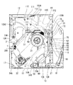
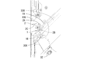
図1は本実施例によるディスク装置のスタンバイ状態を示すベース本体の平面図、図2は同ディスク装置の要部平面図、図3は同装置の要部側面図、図4は同ディスク装置のディスク再生状態を示すベース本体の平面図、図5は同ディスク装置の要部平面図、図6は同装置の要部側面図である。
本実施例によるディスク装置は、ベース本体と蓋体とからシャーシ外装が構成され、このシャーシ外装のフロント面にベゼルが装着される。また本実施例によるディスク装置は、ベゼルに設けたディスク挿入口からディスクを直接挿入するスロットイン型ディスク装置である。
図1に示すように、ディスクへの記録再生機能やディスクのローディング機能を行う各部品は、ベース本体10に装着される。
ベース本体10は、深底部10Aと浅底部10Bが形成され、浅底部10Bによってフロント面からリア面に至るウイング部が形成されている。
ベース本体10のフロント側にはディスクを直接挿入するディスク挿入口11を形成し、ベース本体10のリア面の端部にはコネクタ12を配設している。ベース本体10のディスク挿入口11側にはトラバースベース30が配置され、ベース本体10のコネクタ12側にはリアベース13が配置されている。トラバースベース30とリアベース13とは互いが重ならないように配置されている。リアベース13のベース本体10面側にはプリント基板14が設けられている。
A disk device according to an embodiment of the present invention will be described below.
FIG. 1 is a plan view of a base body showing a standby state of a disk device according to the present embodiment, FIG. 2 is a plan view of the main part of the disk device, FIG. 3 is a side view of the main part of the disk device, and FIG. FIG. 5 is a plan view of the main part of the disk apparatus, and FIG. 6 is a side view of the main part of the apparatus.
In the disk apparatus according to the present embodiment, a chassis exterior is constituted by a base body and a lid, and a bezel is attached to the front surface of the chassis exterior. The disk device according to this embodiment is a slot-in type disk device in which a disk is directly inserted from a disk insertion opening provided in a bezel.
As shown in FIG. 1, each component that performs a disc recording / reproducing function and a disc loading function is mounted on a
The
A
トラバース30は、スピンドルモータ31とピックアップ32とピックアップ32を移動させる駆動手段とを保持している。スピンドルモータ31はトラバース30の一端側に設けられ、ピックアップ32はトラバース30の一端側から他端側までを移動可能に設けられている。またピックアップ32はスタンバイ時にはトラバース30の他端側に配置される。駆動手段は、駆動モータ33Aと、ピックアップ32を摺動させる一対のレール33Bと、駆動モータ33Aの駆動をピックアップ32に伝達する歯車機構とを有し、一対のレール33Bはトラバース30の一端側と他端側とを連接するように両側部に配置されている。駆動モータ33Aはディスク挿入口11側のレール33Bの外方に、駆動軸がレール33Bと平行になるように配置されている。歯車機構は、この駆動モータ33Aとディスク挿入口11側のレール33Bとの間の空間に配置されている。ピックアップ32は、軸受け部30Xによってレール33Bに摺動自在に設けている。
The
トラバース30において、スピンドルモータ31がベース本体10の中央部に位置し、またピックアップ32の往復動範囲がスピンドルモータ31よりもディスク挿入口11側に位置し、またピックアップ32の往復移動方向がディスクの挿入方向と異なるように配設されている。ここで、ピックアップ32の往復移動方向とディスクの挿入方向とは、35〜55度の角度としている。
トラバースベース30は、一対のインシュレータ34A、34Bによってベース本体10に支持されている。
一対のインシュレータ34A、34Bは、スピンドルモータ31の位置よりもピックアップ32の静止位置側に配設している。本実施例では、インシュレータ34Aはディスク挿入口11の内側近傍の一端側に、インシュレータ34Bはディスク挿入口11の内側近傍の中央部に設けている。インシュレータ34A、34Bは、弾性材料からなるダンパー機構を備えている。トラバースベース30は、インシュレータ34A、34Bを支点として、スピンドルモータ31側をベース本体10と近接離間させるように動作する。
In the
The
The pair of insulators 34 </ b> A and 34 </ b> B is disposed closer to the stationary position of the
以下に、カム機構を備えたメインスライダー40とサブスライダー50について説明する。トラバースベース30を変位させるカム機構は、メインスライダー40とサブスライダー50にそれぞれ設けている。ここで、メインスライダー40とサブスライダー50とは、スピンドルモータ31の側方に位置するように配設されている。メインスライダー40は、その一端がシャーシ本体10のフロント面側、その他端がシャーシ本体10のリア面側となる方向に配設されている。また、サブスライダー50は、トラバースベース30とリアベース13との間に、メインスライダー40と直交する方向に配設されている。
トラバースベース30を変位させるカム機構は、第1のカム機構41と第2のカム機構51によって構成される。第1のカム機構41は、メインスライダー40のスピンドルモータ31側の面に、第2のカム機構51は、サブスライダー50のスピンドルモータ31側の面にそれぞれ設けられている。
なお、メインスライダー40とトラバースベース30との間にはベース部材15が設けられ、サブスライダー50とトラバースベース30との間にはベース部材16が設けられている。ここでベース部材15とベース部材16はベース本体10に固定され、ベース部材15に設けた縦溝によってトラバースベース30のカムピンを位置規制し、ベース部材16に設けた縦溝によってトラバースベース30のカムピンを位置規制している。
Below, the
A cam mechanism for displacing the
A
ここで、ベース部材16とサブスライダー50とは、第3のカム機構(図示せず)によって連結している。そしてこの第3のカム機構は、第2のカム機構51によってトラバースベース30をベース本体10に対して離間する方向に移動させる時に、サブスライダー50をベース本体10に対して離間する方向に移動させる機能を備えている。
Here, the
メインスライダー40の一端側にはローディングモータ60が配設されている。ローディングモータ60の駆動軸とメインスライダー40の一端側とは歯車機構を介して連結されている。
このローディングモータ60の駆動によってメインスライダー40を長手方向に摺動させることができる。またメインスライダー40は、カムレバー70によってサブスライダー50と連結している。
カムレバー70は、回動支点71、ピン72、ピン73、及びピン74を有している。ピン72、73はメインスライダー40の上面に設けたカム溝と係合し、ピン74でサブスライダー50の上面に設けたカム溝と係合し、カムレバー70は、回動支点71を軸として回動する。
A loading
The
The
以上説明した、コネクタ12、トラバースベース30、リアベース13、プリント基板14、インシュレータ34A、34B、メインスライダー40、サブスライダー50、及びローディングモータ60は、ベース本体10の深底部10Aに設けられ、これらの部材と蓋体との間に、ディスク挿入空間を形成する。
The
次に、ディスクを挿入するときにディスクを支持するガイド部材と、ディスクを挿入するときに動作するレバー部材について説明する。
深底部10Aのディスク挿入口11近傍の一端側には、所定長さの第1のディスクガイド17が設けられている。この第1のディスクガイド17は、ディスク挿入側から見た断面が、「コ」の字状の溝を有している。この溝によってディスクは支持される。
一方、ディスク挿入口11側の浅底部10Bには、引き込みレバー80が設けられ、この引き込みレバー80の可動側端部に第2のディスクガイド81を備えている。第2のディスクガイド81は、円筒状のローラで構成され、引き込みレバー80の可動側端部に回動自在に設けられている。また、第2のディスクガイド81のローラ外周には溝が形成され、この溝によってディスクは支持される。
引き込みレバー80は、可動側端部が固定側端部よりもディスク挿入口11側で動作するように配置され、固定側端部に回動支点を有している。
Next, a guide member that supports the disk when the disk is inserted and a lever member that operates when the disk is inserted will be described.
A
On the other hand, a pull-in
The pull-in
引き込みレバー80は、サブレバー90によって動作する。
サブレバー90は、可動側の一端に凸部を備え、他端側に回動支点92を備えている。サブレバー90の凸部は、引き込みレバー80の長溝内を摺動する。また、サブレバー90の回動支点92は、メインスライダー40上に位置している。なお、回動支点92は、メインスライダー40とは連動せず、リアベース13に固定されている。またサブレバー90の回動支点92よりも凸部側の下面には、ピン93を備えている。このピン93は、メインスライダー40の上面に設けられたカム溝内を摺動する。従って、サブレバー90は、メインスライダー40の移動にともなって角度が変更され、このサブレバー90の角度の変更によって引き込みレバー80の旋回角度を変更する。すなわち、サブレバー90の動作によって、引き込みレバー80の第2のディスクガイド81がスピンドルモータ31に近接離間するように動作する。
The pull-in
The
ベース本体10の引き込みレバー80と異なる側部には、排出レバーが設けられるがここでは説明を省略する。なお、排出レバーは、リンクアーム105と排出スライダー106を介してメインスライダー40の動きと連動する。ここでリンクアーム105は、軸105Aによってリアベース13に回動自在に設けられ、その一端側はピン105Bを介してメインスライダー40と連接し、その他端側はピン105Cによって排出スライダー106と連接している。排出レバーはカムピンによって排出スライダー106のカム溝と係合している。
A discharge lever is provided on a side portion of the
リアベース13のリア面側には規制レバー110が設けられている。この規制レバー110は、リア面側端部を回動支点111とし、可動側端部にガイド112を備えている。この規制レバー110は、弾性体によってガイド112側が常にフロント側に突出するように付勢されている。また、この規制レバー110は所定位置でリミットスイッチを動作させる。すなわち、ディスクが所定位置まで挿入されると、リミットスイッチがオフし、ローディングモータ60を駆動する。このローディングモータ60の駆動によって、メインスライダー40が摺動する。
また、ベース本体10のフロント側には、フロントガイダー21が設けられている。フロントガイダー21は、ディスク挿入口11の一端側であって、引き込みレバー80とディスク挿入口11との間に配置されている。またこのフロントガイダー21は、ローディングモータ60や歯車機構、メインスライダー40の一部を覆うように、これらの部材よりも蓋体側に設けられている。
A regulating
A
以下にカムレバーの動作について説明する。
ピン73がメインスライダー40のカム溝と係合している間は、カムレバー70は回動しない。この状態はスタンバイ状態である。ディスクがローディングされた後にもしばらくはこの状態であり、トラバースベース30はベース本体10に近接した状態にある。
ディスクの中心がスピンドルモータ31の上方に位置したタイミングで、ピン73はメインスライダー40のカム溝から外れ、カムレバー70は回動を始める。
メインスライダー40に設けられた、第1のカム機構41は、メインスライダー40と同一の方向に移動する。メインスライダー40は、カムレバー70のピン72が摺動する溝を有し、カムレバー70の回動によって、サブスライダー50を移動させ、サブスライダー50を移動させることによって第2のカム機構51を動作させる。
すなわち、メインスライダー40の移動によって、第1のカム機構41は、所定の距離だけ移動し、カムレバー70の回動によって、及び第2のカム機構51は、所定距離だけ移動して、トラバースベース30が変位動作する。
そしてチャッキング動作が終了した段階で、カムレバー70の回動は終了する。
The operation of the cam lever will be described below.
The
At the timing when the center of the disk is positioned above the
The
That is, the movement of the
Then, when the chucking operation is finished, the rotation of the
以下にピックアップ32の移動を規制する構成について説明する。
特に図2及び図3に示すように、ピックストッパー1は、一端を回動支点1A、他端を可動部1Bとして構成し、トラバースベース30の側部に設けている。ピックストッパーレバー2は、軸2Aを中心に回動自在に設けられ、ピックストッパーレバー2の一端部2Bを、ピックストッパー1とベース本体10との間に配置することができる。
図1から図3に示すディスク装置のスタンバイ状態では、ピックストッパーレバー2は、時計方向に弾性体によって付勢されることで、一端部2Bが、ピックストッパー1とベース本体10との間に配置している。
このように、ピックストッパーレバー2の一端部2Bが、ピックストッパー1とベース本体10との間に配置することで、ピックストッパー1の可動部1Bは、ベース本体10から所定間隔を保持した状態となる。従って、ピックアップ32が外部からの衝撃などで移動すると、軸受け部30Xが可動部1Bに当接する。すなわち、軸受け部30Xが可動部1Bに当接することで、ピックアップ32の移動を規制することができる。
A configuration for restricting the movement of the
In particular, as shown in FIGS. 2 and 3, the
In the standby state of the disk device shown in FIGS. 1 to 3, the
As described above, the one
次に、図4から図6を用いてピックアップの移動を規制しない状態について説明する。
上記のチャッキング動作によってディスク装置はディスク再生状態となる。この時、排出スライダー106は、リンクアーム105によってメインスライダー40の動きと連動し、ディスク挿入口11側に移動する。
排出スライダー106は、ディスク挿入口11側に移動することで、ピックストッパーレバー2の他端部2Cを押圧する。
従って、ピックストッパーレバー2は、軸2Aを中心に反時計方向に回動し、ピックストッパーレバー2の一端部2Bは、ピックストッパー1の可動部1Bから離間する。
この状態では、特に図6に示すように、ピックストッパー1の可動部1Bは、ベース本体10に接する位置まで移動する。従って、ピックアップ32が移動しても、軸受け部30Xが可動部1Bに当接することはなく、ピックアップ32は、ピックストッパー1によって移動を規制されない。
Next, the state where the movement of the pickup is not restricted will be described with reference to FIGS.
With the above chucking operation, the disk device enters a disk playback state. At this time, the
The
Accordingly, the
In this state, as shown particularly in FIG. 6, the
本実施例によれば、ピックアップ32の移動を規制するピックストッパー1を設けることで、例えば衝撃などが作用しても、ピックアップ32が退避位置から大きく移動することを防止することができる。
特に本実施例のように、ピックストッパー1の可動部1Bと軸受け部30Xとによってピックアップ32の移動を規制することで、ピックアップ32を損傷することなく所定の位置にピックアップ32を保持することができる。
また本実施例によれば、移動可能なピックストッパーレバー2を設け、ピックストッパーレバー2の一端部2Bが、ピックストッパー1とベース本体10との間に移動することで、ピックストッパー1の可動部1Bを軸受け部30Xに当接する位置に保持し、トラバースベース30の変位量が小さくても確実にピックアップ32の移動を規制することができる。
更に本実施例のように、トラバースベース30と連動して移動する排出スライダー106を設け、ピックストッパーレバー2を排出スライダー106によって移動させることで、確実な動作を行わせることができる。
According to the present embodiment, by providing the
In particular, as in this embodiment, by restricting the movement of the
Further, according to this embodiment, the movable
Further, as in this embodiment, a
本発明は、CD、DVD等のディスク状記録媒体の記録または再生を行うディスク装置において、特に家庭用映像機器やコンピュータの周辺装置として用いられる薄型化の必要なディスク装置に利用できる。 INDUSTRIAL APPLICABILITY The present invention can be applied to a disk device that records or reproduces a disk-shaped recording medium such as a CD or DVD, and particularly to a disk device that needs to be thinned and is used as a peripheral device for home video equipment or a computer.
1 ピックストッパー
1A 回動支点
1B 可動部
2 ピックストッパーレバー
2A 軸
2B 一端部
10 ベース本体
11 ディスク挿入口
30 トラバースベース
32 ピックアップ
DESCRIPTION OF
Claims (2)
前記シャーシ外装のフロント面に形成されているディスクを直接挿入するディスク挿入口と、
前記ベース本体のフロント面側に配置されたトラバースベースと、
前記トラバースベースには、スピンドルモータとピックアップと前記ピックアップが移動するレールとを保持し、
前記トラバースベースの一端側に設けられた前記スピンドルモータと、
前記トラバースベースに移動可能に設けられた前記ピックアップと、
前記ピックアップをスタンバイ時には前記トラバースベースの他端側に配置するスロットイン型ディスク装置であって、
前記トラバースベースに設けられたピックストッパーと、
前記ピックストッパーは、前記トラバースベースが前記ベース本体側に移動している場合には前記ピックアップの移動を規制する位置に移動し、前記トラバースベースが前記蓋体側に移動している場合には前記ピックアップの移動を規制しない位置に移動し、
前記ピックストッパーは一端を回動支点、他端を可動部として構成し、前記ピックアップを軸受け部によって前記レールに摺動自在に設け、前記可動部が前記軸受け部に当接する位置に移動することで前記ピックストッパーが前記ピックアップの移動を規制し、
移動可能なピックストッパーレバーを設け、前記ピックストッパーレバーの一端部が、前記ピックストッパーと前記ベース本体との間を移動することで、前記ピックストッパーの前記可動部を前記軸受け部に当接する位置に保持することを特徴とするスロットイン型ディスク装置。 A base main body and a lid constituting the chassis exterior;
A disk insertion slot for directly inserting a disk formed on the front surface of the chassis exterior;
A traverse base disposed on the front surface side of the base body;
The traverse base holds a spindle motor, a pickup, and a rail on which the pickup moves,
The spindle motor provided on one end side of the traverse base;
The pickup provided movably on the traverse base;
A slot-in type disk device in which the pickup is disposed on the other end side of the traverse base during standby,
A pick stopper provided on the traverse base;
The pick stopper moves to a position where the movement of the pickup is restricted when the traverse base is moved to the base body side, and the pickup stopper is moved to the pickup body when the traverse base is moved to the lid side. move the movement of a position where it does not regulate,
The pick stopper is configured such that one end is a rotation fulcrum and the other end is a movable part, the pickup is slidably provided on the rail by a bearing part, and the movable part moves to a position where it abuts the bearing part. The pick stopper regulates the movement of the pickup,
A movable pick stopper lever is provided, and one end portion of the pick stopper lever moves between the pick stopper and the base body, so that the movable portion of the pick stopper comes into contact with the bearing portion. A slot-in type disk device characterized by being held .
前記トラバースベースと連動して移動するスライダーを設け、前記ピックストッパーレバーが前記スライダーによって移動することを特徴とするスロットイン型ディスク装置。 The slot-in type disk device according to claim 1 ,
A slot-in type disk apparatus comprising a slider that moves in conjunction with the traverse base, and wherein the pick stopper lever is moved by the slider.
Priority Applications (4)
| Application Number | Priority Date | Filing Date | Title |
|---|---|---|---|
| JP2005378944A JP4322868B2 (en) | 2005-12-28 | 2005-12-28 | Slot-in type disk unit |
| PCT/JP2006/322567 WO2007077678A1 (en) | 2005-12-28 | 2006-11-13 | Slot-in type disk device |
| US12/159,195 US7958522B2 (en) | 2005-12-28 | 2006-11-13 | Slot-in type disk apparatus |
| TW095143581A TW200735042A (en) | 2005-12-28 | 2006-11-24 | Slot-in type disk device |
Applications Claiming Priority (1)
| Application Number | Priority Date | Filing Date | Title |
|---|---|---|---|
| JP2005378944A JP4322868B2 (en) | 2005-12-28 | 2005-12-28 | Slot-in type disk unit |
Publications (3)
| Publication Number | Publication Date |
|---|---|
| JP2007179690A JP2007179690A (en) | 2007-07-12 |
| JP2007179690A5 JP2007179690A5 (en) | 2009-01-15 |
| JP4322868B2 true JP4322868B2 (en) | 2009-09-02 |
Family
ID=38228036
Family Applications (1)
| Application Number | Title | Priority Date | Filing Date |
|---|---|---|---|
| JP2005378944A Expired - Fee Related JP4322868B2 (en) | 2005-12-28 | 2005-12-28 | Slot-in type disk unit |
Country Status (4)
| Country | Link |
|---|---|
| US (1) | US7958522B2 (en) |
| JP (1) | JP4322868B2 (en) |
| TW (1) | TW200735042A (en) |
| WO (1) | WO2007077678A1 (en) |
Families Citing this family (1)
| Publication number | Priority date | Publication date | Assignee | Title |
|---|---|---|---|---|
| JP2012027967A (en) * | 2010-07-21 | 2012-02-09 | Jvc Kenwood Corp | Disk conveying mechanism and disk drive device |
Family Cites Families (13)
| Publication number | Priority date | Publication date | Assignee | Title |
|---|---|---|---|---|
| GB8518909D0 (en) | 1985-07-26 | 1985-09-04 | Ae Plc | Engineering components |
| JP2658585B2 (en) * | 1991-01-16 | 1997-09-30 | 三菱電機株式会社 | Disk unit |
| JPH0668634A (en) | 1992-08-24 | 1994-03-11 | Sony Corp | Disk device |
| JP3576704B2 (en) | 1996-06-18 | 2004-10-13 | 株式会社ケンウッド | Disc player |
| JPH1011880A (en) | 1996-06-20 | 1998-01-16 | Alpine Electron Inc | Head holding device in disk device |
| JP3636612B2 (en) | 1999-03-26 | 2005-04-06 | 富士通株式会社 | Optical storage device |
| JP2001202724A (en) | 2000-01-18 | 2001-07-27 | Fujitsu Ten Ltd | Disk unit |
| JP3522235B2 (en) | 2001-05-25 | 2004-04-26 | 松下電器産業株式会社 | Disk unit |
| JP4243049B2 (en) | 2001-09-03 | 2009-03-25 | 富士フイルム株式会社 | Digital data output service system, service method, program |
| JP3903789B2 (en) | 2001-12-28 | 2007-04-11 | 富士通株式会社 | Storage device |
| JP2004019862A (en) | 2002-06-19 | 2004-01-22 | Matsushita Electric Ind Co Ltd | Power transmission apparatus of stepping motor, and disk apparatus with the power transmission apparatus |
| JP2009176385A (en) * | 2008-01-28 | 2009-08-06 | Sharp Corp | Disk drive device |
| CN101894571B (en) * | 2009-05-21 | 2012-07-04 | 飞利浦建兴数位科技股份有限公司 | Disc-loading device for slot-in type CD driver |
-
2005
- 2005-12-28 JP JP2005378944A patent/JP4322868B2/en not_active Expired - Fee Related
-
2006
- 2006-11-13 US US12/159,195 patent/US7958522B2/en not_active Expired - Fee Related
- 2006-11-13 WO PCT/JP2006/322567 patent/WO2007077678A1/en active Application Filing
- 2006-11-24 TW TW095143581A patent/TW200735042A/en unknown
Also Published As
| Publication number | Publication date |
|---|---|
| TW200735042A (en) | 2007-09-16 |
| US20100223636A1 (en) | 2010-09-02 |
| US7958522B2 (en) | 2011-06-07 |
| WO2007077678A1 (en) | 2007-07-12 |
| JP2007179690A (en) | 2007-07-12 |
Similar Documents
| Publication | Publication Date | Title |
|---|---|---|
| JPWO2005101401A1 (en) | Disk unit | |
| JP4103742B2 (en) | Disk drive device | |
| JP4322873B2 (en) | Slot-in type disk unit | |
| JP2005085449A (en) | Disk drive device | |
| JP4758239B2 (en) | Slot-in type disk unit | |
| JP4294616B2 (en) | Slot-in type disk unit | |
| JP4103744B2 (en) | Disk drive device | |
| JP4376756B2 (en) | Disk unit | |
| JP4322868B2 (en) | Slot-in type disk unit | |
| JP4322869B2 (en) | Slot-in type disk unit | |
| JP5158329B2 (en) | Disk unit | |
| JP2005327431A5 (en) | ||
| JP2007179690A5 (en) | ||
| JP2007200377A (en) | Slot-in type disk apparatus | |
| JP4331163B2 (en) | Slot-in type disk unit | |
| JP4754778B2 (en) | Disk drive device | |
| JP4738187B2 (en) | Slot-in type disk unit | |
| JP4813303B2 (en) | Slot-in type disk unit | |
| JP4331171B2 (en) | Slot-in type disk unit | |
| JP4285164B2 (en) | Disk drive device | |
| JP2007200376A (en) | Disk loading device | |
| JP4103743B2 (en) | Disk drive device | |
| JP2007207373A5 (en) | ||
| JP2008165838A (en) | Slot-in type disk device |
Legal Events
| Date | Code | Title | Description |
|---|---|---|---|
| A521 | Written amendment |
Free format text: JAPANESE INTERMEDIATE CODE: A523 Effective date: 20080117 |
|
| A521 | Written amendment |
Free format text: JAPANESE INTERMEDIATE CODE: A523 Effective date: 20081125 |
|
| A621 | Written request for application examination |
Free format text: JAPANESE INTERMEDIATE CODE: A621 Effective date: 20081125 |
|
| A131 | Notification of reasons for refusal |
Free format text: JAPANESE INTERMEDIATE CODE: A131 Effective date: 20090324 |
|
| A521 | Written amendment |
Free format text: JAPANESE INTERMEDIATE CODE: A523 Effective date: 20090413 |
|
| TRDD | Decision of grant or rejection written | ||
| A01 | Written decision to grant a patent or to grant a registration (utility model) |
Free format text: JAPANESE INTERMEDIATE CODE: A01 Effective date: 20090512 |
|
| A01 | Written decision to grant a patent or to grant a registration (utility model) |
Free format text: JAPANESE INTERMEDIATE CODE: A01 |
|
| A61 | First payment of annual fees (during grant procedure) |
Free format text: JAPANESE INTERMEDIATE CODE: A61 Effective date: 20090603 |
|
| R150 | Certificate of patent or registration of utility model |
Free format text: JAPANESE INTERMEDIATE CODE: R150 |
|
| FPAY | Renewal fee payment (event date is renewal date of database) |
Free format text: PAYMENT UNTIL: 20120612 Year of fee payment: 3 |
|
| FPAY | Renewal fee payment (event date is renewal date of database) |
Free format text: PAYMENT UNTIL: 20120612 Year of fee payment: 3 |
|
| FPAY | Renewal fee payment (event date is renewal date of database) |
Free format text: PAYMENT UNTIL: 20130612 Year of fee payment: 4 |
|
| LAPS | Cancellation because of no payment of annual fees |