JP4321739B2 - Cannula stent - Google Patents
Cannula stent Download PDFInfo
- Publication number
- JP4321739B2 JP4321739B2 JP2000587700A JP2000587700A JP4321739B2 JP 4321739 B2 JP4321739 B2 JP 4321739B2 JP 2000587700 A JP2000587700 A JP 2000587700A JP 2000587700 A JP2000587700 A JP 2000587700A JP 4321739 B2 JP4321739 B2 JP 4321739B2
- Authority
- JP
- Japan
- Prior art keywords
- segment
- struts
- stent
- curved portion
- hoop
- Prior art date
- Legal status (The legal status is an assumption and is not a legal conclusion. Google has not performed a legal analysis and makes no representation as to the accuracy of the status listed.)
- Expired - Lifetime
Links
Images


Classifications
-
- A—HUMAN NECESSITIES
- A61—MEDICAL OR VETERINARY SCIENCE; HYGIENE
- A61F—FILTERS IMPLANTABLE INTO BLOOD VESSELS; PROSTHESES; DEVICES PROVIDING PATENCY TO, OR PREVENTING COLLAPSING OF, TUBULAR STRUCTURES OF THE BODY, e.g. STENTS; ORTHOPAEDIC, NURSING OR CONTRACEPTIVE DEVICES; FOMENTATION; TREATMENT OR PROTECTION OF EYES OR EARS; BANDAGES, DRESSINGS OR ABSORBENT PADS; FIRST-AID KITS
- A61F2/00—Filters implantable into blood vessels; Prostheses, i.e. artificial substitutes or replacements for parts of the body; Appliances for connecting them with the body; Devices providing patency to, or preventing collapsing of, tubular structures of the body, e.g. stents
- A61F2/82—Devices providing patency to, or preventing collapsing of, tubular structures of the body, e.g. stents
- A61F2/86—Stents in a form characterised by the wire-like elements; Stents in the form characterised by a net-like or mesh-like structure
- A61F2/90—Stents in a form characterised by the wire-like elements; Stents in the form characterised by a net-like or mesh-like structure characterised by a net-like or mesh-like structure
- A61F2/91—Stents in a form characterised by the wire-like elements; Stents in the form characterised by a net-like or mesh-like structure characterised by a net-like or mesh-like structure made from perforated sheet material or tubes, e.g. perforated by laser cuts or etched holes
-
- A—HUMAN NECESSITIES
- A61—MEDICAL OR VETERINARY SCIENCE; HYGIENE
- A61M—DEVICES FOR INTRODUCING MEDIA INTO, OR ONTO, THE BODY; DEVICES FOR TRANSDUCING BODY MEDIA OR FOR TAKING MEDIA FROM THE BODY; DEVICES FOR PRODUCING OR ENDING SLEEP OR STUPOR
- A61M29/00—Dilators with or without means for introducing media, e.g. remedies
- A61M29/02—Dilators made of swellable material
-
- A—HUMAN NECESSITIES
- A61—MEDICAL OR VETERINARY SCIENCE; HYGIENE
- A61F—FILTERS IMPLANTABLE INTO BLOOD VESSELS; PROSTHESES; DEVICES PROVIDING PATENCY TO, OR PREVENTING COLLAPSING OF, TUBULAR STRUCTURES OF THE BODY, e.g. STENTS; ORTHOPAEDIC, NURSING OR CONTRACEPTIVE DEVICES; FOMENTATION; TREATMENT OR PROTECTION OF EYES OR EARS; BANDAGES, DRESSINGS OR ABSORBENT PADS; FIRST-AID KITS
- A61F2/00—Filters implantable into blood vessels; Prostheses, i.e. artificial substitutes or replacements for parts of the body; Appliances for connecting them with the body; Devices providing patency to, or preventing collapsing of, tubular structures of the body, e.g. stents
- A61F2/82—Devices providing patency to, or preventing collapsing of, tubular structures of the body, e.g. stents
- A61F2/86—Stents in a form characterised by the wire-like elements; Stents in the form characterised by a net-like or mesh-like structure
- A61F2/90—Stents in a form characterised by the wire-like elements; Stents in the form characterised by a net-like or mesh-like structure characterised by a net-like or mesh-like structure
- A61F2/91—Stents in a form characterised by the wire-like elements; Stents in the form characterised by a net-like or mesh-like structure characterised by a net-like or mesh-like structure made from perforated sheet material or tubes, e.g. perforated by laser cuts or etched holes
- A61F2/915—Stents in a form characterised by the wire-like elements; Stents in the form characterised by a net-like or mesh-like structure characterised by a net-like or mesh-like structure made from perforated sheet material or tubes, e.g. perforated by laser cuts or etched holes with bands having a meander structure, adjacent bands being connected to each other
- A61F2002/91516—Stents in a form characterised by the wire-like elements; Stents in the form characterised by a net-like or mesh-like structure characterised by a net-like or mesh-like structure made from perforated sheet material or tubes, e.g. perforated by laser cuts or etched holes with bands having a meander structure, adjacent bands being connected to each other the meander having a change in frequency along the band
-
- A—HUMAN NECESSITIES
- A61—MEDICAL OR VETERINARY SCIENCE; HYGIENE
- A61F—FILTERS IMPLANTABLE INTO BLOOD VESSELS; PROSTHESES; DEVICES PROVIDING PATENCY TO, OR PREVENTING COLLAPSING OF, TUBULAR STRUCTURES OF THE BODY, e.g. STENTS; ORTHOPAEDIC, NURSING OR CONTRACEPTIVE DEVICES; FOMENTATION; TREATMENT OR PROTECTION OF EYES OR EARS; BANDAGES, DRESSINGS OR ABSORBENT PADS; FIRST-AID KITS
- A61F2/00—Filters implantable into blood vessels; Prostheses, i.e. artificial substitutes or replacements for parts of the body; Appliances for connecting them with the body; Devices providing patency to, or preventing collapsing of, tubular structures of the body, e.g. stents
- A61F2/82—Devices providing patency to, or preventing collapsing of, tubular structures of the body, e.g. stents
- A61F2/86—Stents in a form characterised by the wire-like elements; Stents in the form characterised by a net-like or mesh-like structure
- A61F2/90—Stents in a form characterised by the wire-like elements; Stents in the form characterised by a net-like or mesh-like structure characterised by a net-like or mesh-like structure
- A61F2/91—Stents in a form characterised by the wire-like elements; Stents in the form characterised by a net-like or mesh-like structure characterised by a net-like or mesh-like structure made from perforated sheet material or tubes, e.g. perforated by laser cuts or etched holes
- A61F2/915—Stents in a form characterised by the wire-like elements; Stents in the form characterised by a net-like or mesh-like structure characterised by a net-like or mesh-like structure made from perforated sheet material or tubes, e.g. perforated by laser cuts or etched holes with bands having a meander structure, adjacent bands being connected to each other
- A61F2002/91525—Stents in a form characterised by the wire-like elements; Stents in the form characterised by a net-like or mesh-like structure characterised by a net-like or mesh-like structure made from perforated sheet material or tubes, e.g. perforated by laser cuts or etched holes with bands having a meander structure, adjacent bands being connected to each other within the whole structure different bands showing different meander characteristics, e.g. frequency or amplitude
-
- A—HUMAN NECESSITIES
- A61—MEDICAL OR VETERINARY SCIENCE; HYGIENE
- A61F—FILTERS IMPLANTABLE INTO BLOOD VESSELS; PROSTHESES; DEVICES PROVIDING PATENCY TO, OR PREVENTING COLLAPSING OF, TUBULAR STRUCTURES OF THE BODY, e.g. STENTS; ORTHOPAEDIC, NURSING OR CONTRACEPTIVE DEVICES; FOMENTATION; TREATMENT OR PROTECTION OF EYES OR EARS; BANDAGES, DRESSINGS OR ABSORBENT PADS; FIRST-AID KITS
- A61F2/00—Filters implantable into blood vessels; Prostheses, i.e. artificial substitutes or replacements for parts of the body; Appliances for connecting them with the body; Devices providing patency to, or preventing collapsing of, tubular structures of the body, e.g. stents
- A61F2/82—Devices providing patency to, or preventing collapsing of, tubular structures of the body, e.g. stents
- A61F2/86—Stents in a form characterised by the wire-like elements; Stents in the form characterised by a net-like or mesh-like structure
- A61F2/90—Stents in a form characterised by the wire-like elements; Stents in the form characterised by a net-like or mesh-like structure characterised by a net-like or mesh-like structure
- A61F2/91—Stents in a form characterised by the wire-like elements; Stents in the form characterised by a net-like or mesh-like structure characterised by a net-like or mesh-like structure made from perforated sheet material or tubes, e.g. perforated by laser cuts or etched holes
- A61F2/915—Stents in a form characterised by the wire-like elements; Stents in the form characterised by a net-like or mesh-like structure characterised by a net-like or mesh-like structure made from perforated sheet material or tubes, e.g. perforated by laser cuts or etched holes with bands having a meander structure, adjacent bands being connected to each other
- A61F2002/91533—Stents in a form characterised by the wire-like elements; Stents in the form characterised by a net-like or mesh-like structure characterised by a net-like or mesh-like structure made from perforated sheet material or tubes, e.g. perforated by laser cuts or etched holes with bands having a meander structure, adjacent bands being connected to each other characterised by the phase between adjacent bands
-
- A—HUMAN NECESSITIES
- A61—MEDICAL OR VETERINARY SCIENCE; HYGIENE
- A61F—FILTERS IMPLANTABLE INTO BLOOD VESSELS; PROSTHESES; DEVICES PROVIDING PATENCY TO, OR PREVENTING COLLAPSING OF, TUBULAR STRUCTURES OF THE BODY, e.g. STENTS; ORTHOPAEDIC, NURSING OR CONTRACEPTIVE DEVICES; FOMENTATION; TREATMENT OR PROTECTION OF EYES OR EARS; BANDAGES, DRESSINGS OR ABSORBENT PADS; FIRST-AID KITS
- A61F2/00—Filters implantable into blood vessels; Prostheses, i.e. artificial substitutes or replacements for parts of the body; Appliances for connecting them with the body; Devices providing patency to, or preventing collapsing of, tubular structures of the body, e.g. stents
- A61F2/82—Devices providing patency to, or preventing collapsing of, tubular structures of the body, e.g. stents
- A61F2/86—Stents in a form characterised by the wire-like elements; Stents in the form characterised by a net-like or mesh-like structure
- A61F2/90—Stents in a form characterised by the wire-like elements; Stents in the form characterised by a net-like or mesh-like structure characterised by a net-like or mesh-like structure
- A61F2/91—Stents in a form characterised by the wire-like elements; Stents in the form characterised by a net-like or mesh-like structure characterised by a net-like or mesh-like structure made from perforated sheet material or tubes, e.g. perforated by laser cuts or etched holes
- A61F2/915—Stents in a form characterised by the wire-like elements; Stents in the form characterised by a net-like or mesh-like structure characterised by a net-like or mesh-like structure made from perforated sheet material or tubes, e.g. perforated by laser cuts or etched holes with bands having a meander structure, adjacent bands being connected to each other
- A61F2002/9155—Adjacent bands being connected to each other
- A61F2002/91575—Adjacent bands being connected to each other connected peak to trough
-
- A—HUMAN NECESSITIES
- A61—MEDICAL OR VETERINARY SCIENCE; HYGIENE
- A61F—FILTERS IMPLANTABLE INTO BLOOD VESSELS; PROSTHESES; DEVICES PROVIDING PATENCY TO, OR PREVENTING COLLAPSING OF, TUBULAR STRUCTURES OF THE BODY, e.g. STENTS; ORTHOPAEDIC, NURSING OR CONTRACEPTIVE DEVICES; FOMENTATION; TREATMENT OR PROTECTION OF EYES OR EARS; BANDAGES, DRESSINGS OR ABSORBENT PADS; FIRST-AID KITS
- A61F2230/00—Geometry of prostheses classified in groups A61F2/00 - A61F2/26 or A61F2/82 or A61F9/00 or A61F11/00 or subgroups thereof
- A61F2230/0002—Two-dimensional shapes, e.g. cross-sections
- A61F2230/0028—Shapes in the form of latin or greek characters
- A61F2230/0054—V-shaped
Landscapes
- Health & Medical Sciences (AREA)
- Biomedical Technology (AREA)
- Engineering & Computer Science (AREA)
- Animal Behavior & Ethology (AREA)
- Public Health (AREA)
- Heart & Thoracic Surgery (AREA)
- Veterinary Medicine (AREA)
- Life Sciences & Earth Sciences (AREA)
- Vascular Medicine (AREA)
- General Health & Medical Sciences (AREA)
- Physics & Mathematics (AREA)
- Optics & Photonics (AREA)
- Cardiology (AREA)
- Oral & Maxillofacial Surgery (AREA)
- Transplantation (AREA)
- Anesthesiology (AREA)
- Hematology (AREA)
- Media Introduction/Drainage Providing Device (AREA)
Description
【0001】
【発明の属する技術分野】
本発明は一般的に医療装置に関し、特に、カニューレから作られるステントに関する。
【0002】
【従来の技術】
バルーン膨張可能ステントおよび、自己膨張型のステントは、共に金属カニューレから切り取られ、例えば患者の血管内に配置するために膨張する。多くのデザインにおいて、ステントは第一および第二のセグメントからなり、そのうち一方のセグメントは、他方のセグメントより半径方向の強度が大きい。半径方向の強度が小さいほうの第二のセグメントは、第一のセグメントより横方向の可撓性が大きい。このセグメントの組み合わせによって、良好な半径方向の強度と、横方向の可撓性を兼ね備えたステントが提供される。
【0003】
既知のステントの一例が、1998年9月24日付けの、本出願人による米国特許出願第09/160,122号に記載されている。ステントはカニューレから加工され、横方向に相互接続された閉じたセルの長さ方向のセグメントからなる。それぞれの閉じたセルは、円周方向に調節可能な部材によって各端部で相互接続された、一対の長さ方向のストラットによって横方向に配置され、調節可能な部材が変形して円周方向の膨張を可能にする一方、セルの長さは長さ方向のストラットによって維持される。長さ方向セグメントのうち隣接するもの同士は、可撓性の相互接続セグメントによって連結され、これによって、ステントが横方向に曲がることが可能となる。可撓性セグメントは一連の蛇形のベンド(曲げ)を形成する曲線状のストラットから形成され、蛇形ベンドにより横方向の曲げ応力が分散され、一方、ステント全体はわずかしか縮まない。短いストラットが、長さ方向セグメントと、隣接する相互接続セグメントを、相互に接続する。
【0004】
米国特許第5,421,955号、第5,102,417号、および第5,195,984号に、他のカニューレステントが記載されている。多数のステントセグメントを有する、ワイヤフレームステントが、米国特許第5,104,404号に記載されている。
【0005】
【発明が解決しようとする課題】
しかし、ある複数セグメントステントに関する問題点は、比較的高い引張り歪が生じ、金属疲労の原因となることである。従ってこれらのステントが血流による脈動性の膨張や収縮にさらされると、引張り歪の高い部分が結果的に破断する。さらに、患者が体を動かす際にステントが受ける曲げおよびねじれの負荷もまた、金属疲労およびそれによる破断の原因となる。例として、これらの複数セグメントステントは、患者の頚動脈等の種々の末梢血管に対応している。さらに、これらの末梢ステントは、血管に受ける外圧を有する患者の場合等、外部からの応力を受ける可能性があり、つぶれたり変形する原因となる。
【0006】
従って、本発明の目的は、半径方向の強度が高いセグメントと半径方向の強度がそれより低いセグメントを交互に有し、しかも可撓性の高い、カニューレから作られるステントを提供するである。
【0007】
さらに、本発明の目的は、動脈への適用、特に大動脈、頚動脈への適用のように、血流による脈動性の膨張や収縮にさらされる使用状況において特に有用なステントを提供することである。
【0008】
【課題を解決するための手段】
可撓性の高いセグメントと、半径方向の強度またはフープ強度の高いセグメントを交互に有する、本発明によるカニューレステントによって、上述の問題点が解決され、技術的進歩が達成される。可撓性セグメントはそれ自身が前後に弧を描く蛇形の形状を有し、各湾曲部から間隔をあけて対をなすストラットが突出している。ステントが膨張していない状態において、ストラット対は末端部において収束し、それぞれ他の湾曲部に連結して隣接するストラット対に接続し、結果的に円筒形のバンドを形成する。フープセグメントもまた蛇形の形状を有するが、ステントが膨張していない状態において、各湾曲部から平行な対をなして突出するストラットを有し、同様に末端において隣接するストラット対の湾曲部に連結する。それらのストラットうちひとつずつの間に軸連結バーが配置され、隣接するセグメントのストラット対の湾曲部に連結し、フープセグメントと可撓性セグメントを、フープセグメントの少なくとも一端において相互接続する。
【0009】
第一の実施例において、ステントのフープセグメントは、ステントが膨張していない状態では、隣接する平行なストラットの多くの対の間に小さいギャップを有し、隣接する平行なストラットのいくつかの対はその間に比較的大きいギャップを有する。また軸連結バーはそれぞれ大きいギャップ内に配置されるが、バーとその両側の平行ストラットとのギャップは小さい。
【0010】
本発明の第二の実施例において、ステントは均一間隔のストラットを有するフープセグメントを有し、従来技術による可撓性セグメントより大きい半径方向の強度またはフープ強度を提供する。好都合に、ステントの可撓性セグメント内のストラットは、半径方向の強度またはフープ強度のより大きいセグメント内のストラットに比べて、引張り歪が小さくなるような方向と間隔を有する。さらに、この均一間隔ストラットのセグメントは、膨張および圧縮過程において長さ方向の形状を維持する軸相互接続バーを有し、これによって従来の不均一間隔ストラットにおけるようなねじれや変形をなくす。ストラットの均一な間隔によって、引張り歪の大きい領域が、著しく減少し、優れた耐疲労性と寿命を有するステントが提供される。
【0011】
【発明の実施の形態】
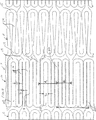
図1はカニューレの円筒形部分から切り取ったステント10の平面図である。ステントは複数の可撓性相互接続セグメント11と、フープ強度または半径方向強度がより高いセグメント12を含む。末端セル13はフープ強度が高いことが望ましい。例えば、カニューレは、バルーン膨張可能ステントに使用される303系または304系ステンレス鋼から作ることができる。他の実施例では、カニューレは、自己膨張型ステントに使用されるニチノール等のニッケル−チタン合金によって形成可能である。これらのニッケル−チタン自己膨張型ステントは、通常、ニチノールの非常に高い弾性を利用している。例えばステントは、カニューレの一片から圧縮された状態で切り取られ、その後半径が大きくなる膨張状態に広げられる。この膨張状態において、ニチノール材料がヒートセットされ、ステントが膨張した構造を記憶する。次にステントが折りたたまれ、ガイドカテーテル内に導入されて、配置部位において展開される。
【0012】
図示されるように、可撓性セグメント11はそれ自身が前後に弧を描く蛇形の形状から成り、ストラット14間のギャップはセグメントの長さ方向の端部から端部に向かって変化する。ステントが膨張しない状態において、ストラット14は各湾曲部15から間隔をおいた一対をなして突出しており、他端において収束して、それぞれが他の湾曲部15に連結して、隣接するストラット対に接続する。このようにして結果的に円筒形のバンドを形成する。
【0013】
フープセグメント12もまた蛇形の形状を有し、一連の長さ方向のストラット16から成り、ストラット16間の間隔は円周方向に変化可能である。隣接するストラット16の各対はそれぞれの湾曲部17から平行に突出し、その間は近接して狭いギャップ18を形成する。あるいは各湾曲部19から平行に突出し、より大きく間隔をあけて大きいギャップ20を形成する。各対のストラット16の末端は隣接するストラットの他の湾曲部に連結する。軸連結バー21が、大きいギャップ20内の特定の湾曲部19から右へ伸び、右に隣接する可とう性セグメント11の湾曲部15に接続する。軸連結バーと隣接するストラット16の間に残されるギャップは狭く、狭いギャップ18と等しい。同様に軸連結バー22が、大きいギャップ20内の特定の湾曲部19から左へ伸び、フープセグメント12の左に配置された、もう一方の隣接する可とう性セグメント11の湾曲部15に接続する。
【0014】
図2は図1のステント10のセグメント11および12の拡大図である。特に、例として長さ方向のストラット16の幅(w)が約0.142mm、その間の狭いギャップ18の広さ(g1)が約0.026mmである。選択された長さ方向ストラット16間の大きいギャップ20の広さ(g2)が約0.194mmである。ストラットの長さと幅は、ステント全体の直径に依存して変化し得る。さらに例として、ステントの元となるカニューレの直径は約1.93mmであり、その金属壁の厚さは0.007インチ(0.17mm)である。この構造において、フープセルセグメントは軸連結バー21,22によって可撓性セグメントに接続されている。上述の、および図示される構造により、図3に示される膨張状態のステントにおいて、フープセルセグメントのストラット間の間隔は不均一である。
【0015】
図2において、軸連結バー21は、円周方向について互いに約1.512mm(C)の間隔をおいている。フープセルセグメント12を右に隣接する可撓性相互接続セグメント11に相互接続する軸連結バー21と、左に隣接する可撓性相互接続セグメント11に相互接続する軸連結バー22が交互に設置される。しかし図示されるように、右側に隣接する可撓性相互接続セグメントと左側に隣接する可撓性相互接続セグメントを接続する軸方向バー21、22の中心線間の距離A1は、0.84mmである。この円周方向距離A1は大きいギャップ20を含む。隣接する可撓性相互接続セグメントを相互接続する、他の中心線間の距離B1は、実質的に最小の幅の狭いギャップ18のみを含み、0.672mである。結果として、円周方向のセグメント間の間隔が不均一であり、距離A1は距離B1より大きい。距離A1と距離B1の和は約1.512mmである。
【0016】
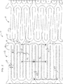
図4は、カニューレの円筒形の一片から切り取った図1のステントの、他の実施例を示す平面図である。ステントは複数の可撓性相互接続セグメント11と、フープ強度または半径方向強度がより高いセグメント12を含む。図示されるように、可撓性セグメント11はそれ自身が前後に弧を描く蛇形の形状から成り、ストラット14間のギャップはセグメントの長さ方向の端部から端部に向かって変化する。フープセルセグメント12は一連の、均一な間隔で円周方向に配置された、長さ方向に伸びるストラット16から成る。図5に最も詳細に示されるように、フープセルセグメント12は長さ方向のストラット16を有し、それらの間に中程度のギャップ23(例えば0.047mm(g3))を有する。中程度のギャップ23の幅は、図1のステントの狭いギャップ18より広く、大きいギャップ20より狭い。結果的に、図4のステントに生じる引張り歪は、図1のステントに生じる引張り歪よりかなり小さい。
【0017】
図5において、ギャップ23が均一間隔であることによって、ステントの半径方向の膨張が均一になる。軸連結バー21,22は円周方向に、互いに均一な間隔(約0.756mm)で配置される。フープセルセグメント12を隣接する可撓性相互接続セグメント11に相互接続する軸連結バー21、22は、円周方向に交互に配置される。しかし図示されるように、右側に隣接する可撓性相互接続セグメント11と左側に隣接する可撓性相互接続セグメント11を接続する軸連結バー21、22の中心線間の距離A2は、0.756mmである。この円周方向距離A 2は、約0.047mmの中程度のギャップ23を含む。隣接する可撓性相互接続セグメントを接続し、均一な中程度のギャップ23のみを含む中心線間距離B2もまた、0.756mmである。結果的に、円周方向のバーの間隔が均一の場合、距離A2とB2は等しい。距離A2とB2の和もまた、約1.512mmである。
【0018】
図6は、フープセルセグメント12と可撓性相互接続セグメント11が軸連結バー21,22によって相互接続されている図4、図5のステント10が、膨張した状態を示す側面図である。図3、および図6内のすべてのストラットと連結バーの幅は十分細く、ステントが血管内の分岐の部分に配置されても、分岐内外への血流がステントによって妨害されることはない。図3の軸連結バー21、22と比較して、図6の軸連結バー21,22はすべて、長さ方向の向きを維持している。図3の軸連結バー21、22は、ねじれ、すべてが長さ方向の同一の向きではなく、縦軸に対して多様な傾斜角度を形成し、ステントの膨張および収縮の際に、ある程度のステントのねじれや曲げの原因となる。軸連結バーのこのねじれは、過度の金属疲労と早期の破断を引き起こす。前述のように、図1のステントのフープセルセグメント12の長さ方向のストラットの間隔が不均一であることによって、図1のステントが動脈内で使用され、連続的な脈動にさらされた場合に、軸連結バー21,22のねじれや、不都合なステントの金属疲労を引き起こす。
【0019】
図7は、末端セル13にアイレット24を設置した図4のステント10を示す平面図である。例えばアイレット24は約0.23mmである。これらのアイレットは、開口部に内に押しつぶされた金製の球のような、種々の放射線不透過性材料で充填することができる。
【0020】
図8、図9において、図1および図4のステントがそれぞれ約7.00mmの直径まで膨張されている。歪のもっとも大きい部位である、半径方向強度の大きいセグメント12の点A、B、およびCにおける、原理的な引張り歪の最大値の概要を、下表に示す。
【0021】
表1

例えば、図1および図8のステントの歪の最大値は約0.012mmで、一方図4および図9のステントの歪の最大値は約0.0078mmであり、図1のステントの引張り歪より約33%低い。従って、図4および図9のステントが、本質的に脈動性であり、それによってステントが連続的に膨張と収縮の繰り返しにさらされる血管内での使用に適している。
【図面の簡単な説明】
【図1】 カニューレの円筒形一片から切り取った、本発明のステントを示す平面図。
【図2】 図1のセグメントの拡大図。
【図3】 図1のステントが膨張した状態を示す側面図。
【図4】 カニューレの円筒形一片から切り取った、本発明のステントのもうひとつの実施例を示す平面図。
【図5】 均一間隔の軸連結バーを有する、図4のステントのセグメントの拡大図。
【図6】 フープセルセグメントと可撓性相互接続セグメントが、軸連結バーによって相互接続された、図5のステントの膨張した状態を示す側面図。
【図7】 ステントの末端セルにアイレットを有する、図4および図5のステントを示す平面図。
【図8】 図1のステントの膨張した状態を示す図。
【図9】 図4のステントの膨張した状態を示す図。
【符号の説明】
10 ステント
11 可撓性相互接続セグメント
12 高フープ強度セグメント
13 末端セルセグメント
14 ストラット
15 湾曲部
16 ストラット
17 湾曲部
18 狭いギャップ
19 湾曲部
20 大きいギャップ
21 軸連結バー
22 軸連結バー
23 中程度のギャップ
24 アイレット[0001]
BACKGROUND OF THE INVENTION
The present invention relates generally to medical devices, and more particularly to stents made from cannulas.
[0002]
[Prior art]
Balloon expandable stents and self-expanding stents are both cut from a metal cannula and expanded, for example, for placement in a patient's blood vessel. In many designs, the stent consists of first and second segments, one of which has a greater radial strength than the other. The second segment having a smaller radial strength is more flexible in the lateral direction than the first segment. This combination of segments provides a stent that combines good radial strength and lateral flexibility.
[0003]
An example of a known stent is described in commonly assigned US patent application Ser. No. 09 / 160,122, dated Sep. 24, 1998. Stents are fabricated from cannulas and consist of lengthwise segments of closed cells interconnected laterally. Each closed cell is laterally arranged by a pair of longitudinal struts interconnected at each end by a circumferentially adjustable member, and the adjustable member is deformed to circumferentially The cell length is maintained by longitudinal struts. Adjacent ones of the longitudinal segments are connected by flexible interconnect segments, which allows the stent to bend laterally. The flexible segments are formed from curvilinear struts that form a series of serpentine bends, which distribute the lateral bending stress while the entire stent shrinks only slightly. Short struts connect the longitudinal segments and adjacent interconnect segments to each other.
[0004]
Other cannula stents are described in US Pat. Nos. 5,421,955, 5,102,417, and 5,195,984. A wire frame stent having multiple stent segments is described in US Pat. No. 5,104,404.
[0005]
[Problems to be solved by the invention]
However, a problem with certain multi-segment stents is that relatively high tensile strains are produced and cause metal fatigue. Thus, when these stents are exposed to pulsatile expansion or contraction due to blood flow, the high tensile strain portion will eventually break. In addition, bending and twisting loads experienced by the stent as the patient moves the body also cause metal fatigue and resulting fracture. By way of example, these multi-segment stents correspond to various peripheral blood vessels such as the patient's carotid artery. In addition, these peripheral stents can be subjected to external stress, such as in patients with external pressure on the blood vessels, causing collapse or deformation.
[0006]
Accordingly, it is an object of the present invention to provide a highly flexible stent made of a cannula having alternating high-strength and low-strength segments.
[0007]
Furthermore, it is an object of the present invention to provide a stent that is particularly useful in use situations where it is exposed to pulsatile expansion or contraction due to blood flow, such as application to arteries, particularly aorta and carotid arteries.
[0008]
[Means for Solving the Problems]
With the cannula stent according to the invention having alternating highly flexible segments and high radial or hoop strength segments, the above-mentioned problems are solved and technical advancements are achieved. The flexible segment has a serpentine shape that arcs back and forth, and a pair of struts project from each curved portion at intervals. In the unexpanded state of the stent, the strut pairs converge at the distal ends, each connected to another curved portion and connected to an adjacent strut pair, resulting in a cylindrical band. The hoop segments also have a serpentine shape, but with the struts projecting in parallel pairs from each bend in the unexpanded state of the stent, similarly to the bends of the adjacent strut pair at the ends. Link. A shaft coupling bar is disposed between each of the struts and couples to the curved portion of the strut pair of adjacent segments to interconnect the hoop segment and the flexible segment at at least one end of the hoop segment.
[0009]
In a first embodiment, the hoop segment of the stent has a small gap between many pairs of adjacent parallel struts in the unexpanded state of the stent, and several pairs of adjacent parallel struts. Have a relatively large gap between them. The shaft connecting bars are each arranged in a large gap, but the gap between the bar and the parallel struts on both sides thereof is small.
[0010]
In a second embodiment of the present invention, the stent has hoop segments with uniformly spaced struts to provide greater radial strength or hoop strength than flexible segments according to the prior art. Conveniently, the struts in the flexible segment of the stent have a direction and spacing that results in less tensile strain than struts in the segment with greater radial or hoop strength. In addition, the uniformly spaced strut segments have an axial interconnect bar that maintains a longitudinal shape during the expansion and compression process, thereby eliminating twisting and deformation as in conventional non-uniformly spaced struts. Due to the uniform spacing of the struts, the area of high tensile strain is significantly reduced, providing a stent with excellent fatigue resistance and life.
[0011]
DETAILED DESCRIPTION OF THE INVENTION
FIG. 1 is a plan view of a
[0012]
As shown, the
[0013]
The
[0014]
FIG. 2 is an enlarged view of
[0015]
In FIG. 2, the shaft coupling bars 21 are spaced from each other in the circumferential direction by about 1.512 mm (C). The
[0016]
4 is a plan view of another embodiment of the stent of FIG. 1 taken from a cylindrical piece of cannula. The stent includes a plurality of
[0017]
In FIG. 5, the
[0018]
FIG. 6 is a side view showing the expanded state of the
[0019]
FIG. 7 is a plan view showing the
[0020]
8 and 9, the stents of FIGS. 1 and 4 are each expanded to a diameter of about 7.00 mm. The table below shows an outline of the maximum value of the principle tensile strain at points A, B, and C of the
[0021]
Table 1
For example, the maximum strain of the stent of FIGS. 1 and 8 is about 0.012 mm, while the maximum strain of the stent of FIGS. 4 and 9 is about 0.0078 mm, which is greater than the tensile strain of the stent of FIG. About 33% lower. Thus, the stent of FIGS. 4 and 9 is inherently pulsatile, making it suitable for use in blood vessels where the stent is continuously subjected to repeated expansion and contraction.
[Brief description of the drawings]
FIG. 1 is a plan view of a stent of the present invention cut from a cylindrical piece of a cannula.
FIG. 2 is an enlarged view of the segment of FIG.
3 is a side view showing a state where the stent of FIG. 1 is expanded. FIG.
FIG. 4 is a plan view showing another embodiment of the stent of the present invention cut from a cylindrical piece of cannula.
FIG. 5 is an enlarged view of a segment of the stent of FIG. 4 with uniformly spaced axial connection bars.
6 is a side view showing the expanded state of the stent of FIG. 5 with the hoop cell segment and the flexible interconnect segment interconnected by a shaft coupling bar. FIG.
7 is a plan view of the stent of FIGS. 4 and 5 having an eyelet in the end cell of the stent. FIG.
8 is a view showing an expanded state of the stent of FIG. 1. FIG.
9 shows the expanded state of the stent of FIG. 4. FIG.
[Explanation of symbols]
10
Claims (8)
ステントが膨張していない状態において、第1の湾曲部(17)及び該第1の湾曲部よりも曲率半径が大きい第2の湾曲部(19)から平行に対をなして伸びる、複数の第2ストラット(16)を有するフープセグメント(12)と、
を備えるカニューレステント(10)であって、
前記可撓性セグメント(11)と前記フープセグメント(12)とは、前記可撓性セグメント(11)の湾曲部(15)から前記フープセグメント(12)の第2の湾曲部(19)へと延びる長手方向連結バー(21、22)によって連結され、前記長手方向連結バー(21、22)は、前記フープセグメント(12)における前記第2の湾曲部(19)と接続する平行なストラット(16)の隣接する対のストラットの間に配置され、
前記長手方向連結バー(21、22)は、前記可撓性セグメント(11)のうちいくつかの湾曲部(15)を該湾曲部の外側表面のみで連結し、
前記可撓性セグメント(11)の前記湾曲部(15)の曲率半径は、前記フープセグメント(12)の半円形状である前記第1の湾曲部(17)の曲率半径よりも大きく、
前記長手方向連結バー(21、22)が連結されていない前記可撓性セグメント(11)の湾曲部(15)は、前記第1ストラット(14)と略同一の幅と材料からなり、それにより前記可撓性セグメント(11)の前記第1ストラット(14)はほぼ全て均一に開き、
前記第1の湾曲部(17)は前記第2の湾曲部(19)と隣接して設けられ、かつ、前記フープセグメント(12)の前記ストラット(16)とのみ連結し、このため、前記カニューレステントが拡張又は収縮されるときに、前記フープセグメント(12)の拡張性が向上すると同時に、前記ストラット(16)及び前記第1及び第2の湾曲部(17、19)における引っ張り歪が最小となり、
該カニューレステントが拡張していない状態では、前記可撓性セグメント(11)のストラット対(14)のそれぞれのストラットは該ストラットの先端で収束し、このため、前記カニューレステントが拡張又は収縮されるときに、前記可撓性セグメント(11)の拡張性が向上すると同時に、前記ストラット(14)及び前記湾曲部(15)における引っ張り歪が最小となる、
ことを特徴とするカニューレステント。A plurality of first struts (14) extending in pairs from the bends (15), the tips of the struts being respectively coupled to the bends of adjacent strut pairs, the struts and the bends being a circle of the stent; A flexible segment (11) arranged continuously around the circumference, wherein the curved portion (15) is semicircular;
In the unexpanded state, the first curved portion (17) and the second curved portion (19) having a larger radius of curvature than the first curved portion extend in parallel to form a plurality of second curved portions. A hoop segment (12) having two struts (16);
A cannula stent (10) comprising:
The flexible segment (11) and the hoop segment (12) extend from the curved portion (15) of the flexible segment (11) to the second curved portion (19) of the hoop segment (12). Connected by extending longitudinal connecting bars (21, 22), the longitudinal connecting bars (21, 22) are parallel struts (16) connected to the second bend (19) in the hoop segment (12). Between adjacent pair of struts)
The longitudinal connecting bars (21, 22) connect several curved portions (15) of the flexible segments (11) only at the outer surface of the curved portions,
The radius of curvature of the curved portion (15) of the flexible segment (11) is greater than the radius of curvature of the first curved portion (17) that is semicircular in the hoop segment (12),
The curved portion (15) of the flexible segment (11) to which the longitudinal connecting bars (21, 22) are not connected is made of substantially the same width and material as the first strut (14), thereby The first struts (14) of the flexible segment (11) open almost uniformly,
The first bend (17) is provided adjacent to the second bend (19) and is connected only to the struts (16) of the hoop segment (12), so that the cannula When the stent is expanded or contracted, the expandability of the hoop segment (12) is improved, and at the same time, the tensile strain in the strut (16) and the first and second curved portions (17, 19) is minimized. ,
In the unexpanded state of the cannula stent, each strut of the flexible segment (11) strut pair (14) converges at the tip of the strut so that the cannula stent is expanded or contracted. Sometimes, the expandability of the flexible segment (11) is improved, and at the same time, the tensile strain in the strut (14) and the curved portion (15) is minimized.
A cannula stent characterized by that.
前記平行なストラット(16)のうち、残りのストラットは、最短の直線部分を有する第2の湾曲部(19)の丸い接合部から伸びるストラット(16)の幅の1.5倍の幅を有する第2ギャップ(20)だけ相互に離間している、
ことを特徴とする請求項1に記載のカニューレステント。At least some of the parallel struts (16) of the hoop segment (12) extend from a semi-circular first bend (17) and have a first width that is half the width of the strut (16). Spaced apart from each other by a gap (18),
Of the parallel struts (16), the remaining struts have a width 1.5 times the width of the strut (16) extending from the round joint of the second curved portion (19) having the shortest straight portion. Spaced apart from each other by a second gap (20) ,
The cannula stent according to claim 1.
ことを特徴とする請求項1に記載のカニューレステント。Adjacent pairs of the parallel struts (16) of the hoop segments (12) are spaced apart from each other by an intermediate gap (23) having a width equal to the width of the struts extending from the semicircular first curved portion (17). Or spaced apart by the intermediate gap (23) from a longitudinal connecting bar (21, 22) between adjacent pairs of parallel struts (16), and adjacent pairs of parallel struts (16) Extends from the round joint of the second bend ( 19 ) having a linear portion of minute length,
The cannula stent according to claim 1.
前記フープセグメント(12)の第2の湾曲部(19)のうちのある湾曲部は、隣接していない、
ことを特徴とする請求項1乃至3のいずれかに記載のカニューレステント。Some of the curved portions (15) of the flexible segment (11) are not adjacent,
A curved portion of the second curved portion (19) of the hoop segment (12) is not adjacent,
The cannula stent according to any one of claims 1 to 3.
ことを特徴とする請求項1乃至4のいずれかに記載のカニューレステント。5. Cannula stent according to any of claims 1 to 4, characterized in that the stent comprises a hoop segment as a terminal segment (13).
ことを特徴とする請求項1乃至5のいずれかに記載のカニューレステント。The cannula stent according to any one of claims 1 to 5, wherein the stent is made of a shape memory alloy.
ことを特徴とする請求項1乃至6のいずれかに記載のカニューレステント。The cannula stent according to any one of claims 1 to 6, wherein the stent is made of a material selected from the group consisting of nickel-titanium alloy and stainless steel.
ことを特徴とする請求項1乃至4のいずれかに記載のカニューレステント。 The first curved portion (17) of the hoop segment (12) to which the longitudinal connecting bars (21, 22) are not connected is all semicircular. The described cannula stent.
Applications Claiming Priority (3)
| Application Number | Priority Date | Filing Date | Title |
|---|---|---|---|
| US11293998P | 1998-12-18 | 1998-12-18 | |
| US60/112,939 | 1998-12-18 | ||
| PCT/US1999/029904 WO2000035378A1 (en) | 1998-12-18 | 1999-12-16 | Cannula stent |
Related Child Applications (1)
| Application Number | Title | Priority Date | Filing Date |
|---|---|---|---|
| JP2008272437A Division JP4898990B2 (en) | 1998-12-18 | 2008-10-22 | Cannula stent |
Publications (3)
| Publication Number | Publication Date |
|---|---|
| JP2002532136A JP2002532136A (en) | 2002-10-02 |
| JP2002532136A5 JP2002532136A5 (en) | 2007-02-15 |
| JP4321739B2 true JP4321739B2 (en) | 2009-08-26 |
Family
ID=22346664
Family Applications (2)
| Application Number | Title | Priority Date | Filing Date |
|---|---|---|---|
| JP2000587700A Expired - Lifetime JP4321739B2 (en) | 1998-12-18 | 1999-12-16 | Cannula stent |
| JP2008272437A Expired - Lifetime JP4898990B2 (en) | 1998-12-18 | 2008-10-22 | Cannula stent |
Family Applications After (1)
| Application Number | Title | Priority Date | Filing Date |
|---|---|---|---|
| JP2008272437A Expired - Lifetime JP4898990B2 (en) | 1998-12-18 | 2008-10-22 | Cannula stent |
Country Status (8)
| Country | Link |
|---|---|
| EP (1) | EP1139918B1 (en) |
| JP (2) | JP4321739B2 (en) |
| KR (1) | KR20010089543A (en) |
| AU (1) | AU743675B2 (en) |
| CA (1) | CA2349256C (en) |
| DE (1) | DE69938058T2 (en) |
| HK (1) | HK1042223B (en) |
| WO (1) | WO2000035378A1 (en) |
Families Citing this family (12)
| Publication number | Priority date | Publication date | Assignee | Title |
|---|---|---|---|---|
| AU745664B2 (en) * | 1994-07-28 | 2002-03-28 | Medinol Ltd | A stent |
| GB0020491D0 (en) * | 2000-08-18 | 2000-10-11 | Angiomed Ag | Stent with attached element and method of making such a stent |
| DE60132603T3 (en) * | 2000-09-22 | 2012-04-19 | Boston Scientific Ltd. | FLEXIBLE AND EXTENDABLE STENT |
| US7037330B1 (en) * | 2000-10-16 | 2006-05-02 | Scimed Life Systems, Inc. | Neurovascular stent and method |
| US7025777B2 (en) | 2002-07-31 | 2006-04-11 | Unison Therapeutics, Inc. | Flexible and conformable stent and method of forming same |
| US8282678B2 (en) | 2002-11-13 | 2012-10-09 | Allium Medical Solutions Ltd. | Endoluminal lining |
| EP1744705B8 (en) | 2004-05-05 | 2009-10-07 | Invatec S.p.A | Endoluminal prosthesis |
| JP4844394B2 (en) * | 2004-06-25 | 2011-12-28 | 日本ゼオン株式会社 | Stent |
| EP2364676B1 (en) | 2005-06-30 | 2018-12-19 | Abbott Laboratories | Endoprosthesis having foot extensions |
| JP2010516393A (en) | 2007-01-29 | 2010-05-20 | クック・インコーポレイテッド | Medical prosthesis and manufacturing method |
| JP5597250B2 (en) * | 2009-04-10 | 2014-10-01 | コヴィディエン リミテッド パートナーシップ | Grafts with high fatigue resistance, graft delivery systems, and methods of use |
| KR101968885B1 (en) * | 2012-03-16 | 2019-04-15 | 테루모 코퍼레이션 | Stent and stent delivery device |
Family Cites Families (13)
| Publication number | Priority date | Publication date | Assignee | Title |
|---|---|---|---|---|
| US5102417A (en) | 1985-11-07 | 1992-04-07 | Expandable Grafts Partnership | Expandable intraluminal graft, and method and apparatus for implanting an expandable intraluminal graft |
| CA1322628C (en) | 1988-10-04 | 1993-10-05 | Richard A. Schatz | Expandable intraluminal graft |
| IE73670B1 (en) | 1989-10-02 | 1997-07-02 | Medtronic Inc | Articulated stent |
| DE69510986T2 (en) * | 1994-04-25 | 1999-12-02 | Advanced Cardiovascular System | Radiation-opaque stent markings |
| AU3783195A (en) * | 1994-11-15 | 1996-05-23 | Advanced Cardiovascular Systems Inc. | Intraluminal stent for attaching a graft |
| CA2192520A1 (en) * | 1996-03-05 | 1997-09-05 | Ian M. Penn | Expandable stent and method for delivery of same |
| CA2248718A1 (en) * | 1996-03-05 | 1997-09-12 | Divysio Solutions Ulc. | Expandable stent and method for delivery of same |
| NZ331269A (en) * | 1996-04-10 | 2000-01-28 | Advanced Cardiovascular System | Expandable stent, its structural strength varying along its length |
| US5922020A (en) * | 1996-08-02 | 1999-07-13 | Localmed, Inc. | Tubular prosthesis having improved expansion and imaging characteristics |
| US6344055B1 (en) * | 1997-05-14 | 2002-02-05 | Novo Rps Ulc | Method for production of an expandable stent |
| US5843175A (en) * | 1997-06-13 | 1998-12-01 | Global Therapeutics, Inc. | Enhanced flexibility surgical stent |
| CA2295682C (en) * | 1997-07-08 | 2011-01-04 | Novo Rps Ulc | Expandable stent |
| ES2290995T3 (en) * | 1997-09-24 | 2008-02-16 | Med Institute, Inc. | RADIALLY EXPANDABLE ENDOPROTESIS. |
-
1999
- 1999-12-16 AU AU27100/00A patent/AU743675B2/en not_active Expired
- 1999-12-16 KR KR1020017006969A patent/KR20010089543A/en not_active Application Discontinuation
- 1999-12-16 EP EP99968899A patent/EP1139918B1/en not_active Expired - Lifetime
- 1999-12-16 DE DE69938058T patent/DE69938058T2/en not_active Expired - Lifetime
- 1999-12-16 WO PCT/US1999/029904 patent/WO2000035378A1/en active IP Right Grant
- 1999-12-16 JP JP2000587700A patent/JP4321739B2/en not_active Expired - Lifetime
- 1999-12-16 CA CA002349256A patent/CA2349256C/en not_active Expired - Lifetime
-
2002
- 2002-03-22 HK HK02102214.4A patent/HK1042223B/en unknown
-
2008
- 2008-10-22 JP JP2008272437A patent/JP4898990B2/en not_active Expired - Lifetime
Also Published As
| Publication number | Publication date |
|---|---|
| HK1042223B (en) | 2008-04-03 |
| JP2009050716A (en) | 2009-03-12 |
| HK1042223A1 (en) | 2002-08-09 |
| DE69938058D1 (en) | 2008-03-13 |
| DE69938058T2 (en) | 2009-01-22 |
| WO2000035378A1 (en) | 2000-06-22 |
| EP1139918B1 (en) | 2008-01-23 |
| KR20010089543A (en) | 2001-10-06 |
| CA2349256C (en) | 2009-04-14 |
| CA2349256A1 (en) | 2000-06-22 |
| EP1139918A1 (en) | 2001-10-10 |
| JP4898990B2 (en) | 2012-03-21 |
| JP2002532136A (en) | 2002-10-02 |
| AU743675B2 (en) | 2002-01-31 |
| AU2710000A (en) | 2000-07-03 |
Similar Documents
| Publication | Publication Date | Title |
|---|---|---|
| JP4898990B2 (en) | Cannula stent | |
| US6743252B1 (en) | Cannula stent | |
| AU2002304381B2 (en) | Longitudinally flexible stent | |
| US7828835B2 (en) | Longitudinally flexible stent | |
| JP4912321B2 (en) | Variable curvature stent rim, stent, and medical prosthesis including stent | |
| EP0955950B1 (en) | Flat wire stent | |
| EP1703856B1 (en) | Longitudinally flexible stent | |
| AU2002304381A1 (en) | Longitudinally flexible stent | |
| EP1129673A2 (en) | Longitudinally flexible stent | |
| JP2005505345A (en) | Kanyo lestent | |
| US20150080999A1 (en) | Self-expanding stent | |
| US7621947B2 (en) | Longitudinally flexible stent | |
| US8496699B2 (en) | Longitudinally flexible stent | |
| JP2004344204A (en) | Uniformly expanded flexible stent | |
| AU2002304380A1 (en) | Longitudinally flexible stent | |
| CA2590373A1 (en) | Longitudinally flexible stent |
Legal Events
| Date | Code | Title | Description |
|---|---|---|---|
| RD13 | Notification of appointment of power of sub attorney |
Free format text: JAPANESE INTERMEDIATE CODE: A7433 Effective date: 20031126 |
|
| A072 | Dismissal of procedure [no reply to invitation to correct request for examination] |
Free format text: JAPANESE INTERMEDIATE CODE: A073 Effective date: 20040615 |
|
| A625 | Written request for application examination (by other person) |
Free format text: JAPANESE INTERMEDIATE CODE: A625 Effective date: 20061201 |
|
| A521 | Written amendment |
Free format text: JAPANESE INTERMEDIATE CODE: A523 Effective date: 20061221 |
|
| RD02 | Notification of acceptance of power of attorney |
Free format text: JAPANESE INTERMEDIATE CODE: A7422 Effective date: 20070525 |
|
| A977 | Report on retrieval |
Free format text: JAPANESE INTERMEDIATE CODE: A971007 Effective date: 20071121 |
|
| A131 | Notification of reasons for refusal |
Free format text: JAPANESE INTERMEDIATE CODE: A131 Effective date: 20071127 |
|
| A601 | Written request for extension of time |
Free format text: JAPANESE INTERMEDIATE CODE: A601 Effective date: 20080226 |
|
| A602 | Written permission of extension of time |
Free format text: JAPANESE INTERMEDIATE CODE: A602 Effective date: 20080304 |
|
| A601 | Written request for extension of time |
Free format text: JAPANESE INTERMEDIATE CODE: A601 Effective date: 20080325 |
|
| A602 | Written permission of extension of time |
Free format text: JAPANESE INTERMEDIATE CODE: A602 Effective date: 20080401 |
|
| A601 | Written request for extension of time |
Free format text: JAPANESE INTERMEDIATE CODE: A601 Effective date: 20080425 |
|
| RD04 | Notification of resignation of power of attorney |
Free format text: JAPANESE INTERMEDIATE CODE: A7424 Effective date: 20080428 |
|
| A602 | Written permission of extension of time |
Free format text: JAPANESE INTERMEDIATE CODE: A602 Effective date: 20080507 |
|
| A521 | Written amendment |
Free format text: JAPANESE INTERMEDIATE CODE: A523 Effective date: 20080527 |
|
| A02 | Decision of refusal |
Free format text: JAPANESE INTERMEDIATE CODE: A02 Effective date: 20080624 |
|
| A521 | Written amendment |
Free format text: JAPANESE INTERMEDIATE CODE: A523 Effective date: 20081022 |
|
| A911 | Transfer to examiner for re-examination before appeal (zenchi) |
Free format text: JAPANESE INTERMEDIATE CODE: A911 Effective date: 20081104 |
|
| A131 | Notification of reasons for refusal |
Free format text: JAPANESE INTERMEDIATE CODE: A131 Effective date: 20090120 |
|
| A521 | Written amendment |
Free format text: JAPANESE INTERMEDIATE CODE: A523 Effective date: 20090420 |
|
| TRDD | Decision of grant or rejection written | ||
| A01 | Written decision to grant a patent or to grant a registration (utility model) |
Free format text: JAPANESE INTERMEDIATE CODE: A01 Effective date: 20090519 |
|
| A01 | Written decision to grant a patent or to grant a registration (utility model) |
Free format text: JAPANESE INTERMEDIATE CODE: A01 |
|
| A61 | First payment of annual fees (during grant procedure) |
Free format text: JAPANESE INTERMEDIATE CODE: A61 Effective date: 20090528 |
|
| R150 | Certificate of patent or registration of utility model |
Free format text: JAPANESE INTERMEDIATE CODE: R150 Ref document number: 4321739 Country of ref document: JP Free format text: JAPANESE INTERMEDIATE CODE: R150 |
|
| FPAY | Renewal fee payment (event date is renewal date of database) |
Free format text: PAYMENT UNTIL: 20120612 Year of fee payment: 3 |
|
| FPAY | Renewal fee payment (event date is renewal date of database) |
Free format text: PAYMENT UNTIL: 20120612 Year of fee payment: 3 |
|
| FPAY | Renewal fee payment (event date is renewal date of database) |
Free format text: PAYMENT UNTIL: 20130612 Year of fee payment: 4 |
|
| R250 | Receipt of annual fees |
Free format text: JAPANESE INTERMEDIATE CODE: R250 |
|
| R250 | Receipt of annual fees |
Free format text: JAPANESE INTERMEDIATE CODE: R250 |
|
| R250 | Receipt of annual fees |
Free format text: JAPANESE INTERMEDIATE CODE: R250 |
|
| R250 | Receipt of annual fees |
Free format text: JAPANESE INTERMEDIATE CODE: R250 |
|
| R250 | Receipt of annual fees |
Free format text: JAPANESE INTERMEDIATE CODE: R250 |
|
| R250 | Receipt of annual fees |
Free format text: JAPANESE INTERMEDIATE CODE: R250 |
|
| R250 | Receipt of annual fees |
Free format text: JAPANESE INTERMEDIATE CODE: R250 |
|
| R250 | Receipt of annual fees |
Free format text: JAPANESE INTERMEDIATE CODE: R250 |
|
| EXPY | Cancellation because of completion of term |