JP4319357B2 - Medication applicator - Google Patents
Medication applicator Download PDFInfo
- Publication number
- JP4319357B2 JP4319357B2 JP2000593357A JP2000593357A JP4319357B2 JP 4319357 B2 JP4319357 B2 JP 4319357B2 JP 2000593357 A JP2000593357 A JP 2000593357A JP 2000593357 A JP2000593357 A JP 2000593357A JP 4319357 B2 JP4319357 B2 JP 4319357B2
- Authority
- JP
- Japan
- Prior art keywords
- housing
- plunger
- medicament
- applicator
- distal end
- Prior art date
- Legal status (The legal status is an assumption and is not a legal conclusion. Google has not performed a legal analysis and makes no representation as to the accuracy of the status listed.)
- Expired - Lifetime
Links
Images


Classifications
-
- A—HUMAN NECESSITIES
- A61—MEDICAL OR VETERINARY SCIENCE; HYGIENE
- A61F—FILTERS IMPLANTABLE INTO BLOOD VESSELS; PROSTHESES; DEVICES PROVIDING PATENCY TO, OR PREVENTING COLLAPSING OF, TUBULAR STRUCTURES OF THE BODY, e.g. STENTS; ORTHOPAEDIC, NURSING OR CONTRACEPTIVE DEVICES; FOMENTATION; TREATMENT OR PROTECTION OF EYES OR EARS; BANDAGES, DRESSINGS OR ABSORBENT PADS; FIRST-AID KITS
- A61F9/00—Methods or devices for treatment of the eyes; Devices for putting-in contact lenses; Devices to correct squinting; Apparatus to guide the blind; Protective devices for the eyes, carried on the body or in the hand
- A61F9/0008—Introducing ophthalmic products into the ocular cavity or retaining products therein
-
- A—HUMAN NECESSITIES
- A61—MEDICAL OR VETERINARY SCIENCE; HYGIENE
- A61M—DEVICES FOR INTRODUCING MEDIA INTO, OR ONTO, THE BODY; DEVICES FOR TRANSDUCING BODY MEDIA OR FOR TAKING MEDIA FROM THE BODY; DEVICES FOR PRODUCING OR ENDING SLEEP OR STUPOR
- A61M31/00—Devices for introducing or retaining media, e.g. remedies, in cavities of the body
-
- A—HUMAN NECESSITIES
- A61—MEDICAL OR VETERINARY SCIENCE; HYGIENE
- A61M—DEVICES FOR INTRODUCING MEDIA INTO, OR ONTO, THE BODY; DEVICES FOR TRANSDUCING BODY MEDIA OR FOR TAKING MEDIA FROM THE BODY; DEVICES FOR PRODUCING OR ENDING SLEEP OR STUPOR
- A61M2205/00—General characteristics of the apparatus
- A61M2205/27—General characteristics of the apparatus preventing use
- A61M2205/273—General characteristics of the apparatus preventing use preventing reuse, e.g. of disposables
Landscapes
- Health & Medical Sciences (AREA)
- Public Health (AREA)
- Veterinary Medicine (AREA)
- Engineering & Computer Science (AREA)
- Biomedical Technology (AREA)
- Heart & Thoracic Surgery (AREA)
- Life Sciences & Earth Sciences (AREA)
- Animal Behavior & Ethology (AREA)
- General Health & Medical Sciences (AREA)
- Vascular Medicine (AREA)
- Ophthalmology & Optometry (AREA)
- Anesthesiology (AREA)
- Hematology (AREA)
- Infusion, Injection, And Reservoir Apparatuses (AREA)
- Coating Apparatus (AREA)
- Polysaccharides And Polysaccharide Derivatives (AREA)
- Confectionery (AREA)
- Valve Device For Special Equipments (AREA)
- Containers And Packaging Bodies Having A Special Means To Remove Contents (AREA)
- Media Introduction/Drainage Providing Device (AREA)
- Acyclic And Carbocyclic Compounds In Medicinal Compositions (AREA)
- Pharmaceuticals Containing Other Organic And Inorganic Compounds (AREA)
Abstract
Description
【0001】
【発明の属する技術分野】
本発明は、容器(コンテナ)及びアプリケーターのシステム全般に関するものであり、具体的には、本発明は目標部位に対し医薬を投与するための使い捨て可能な投薬容器(コンテナ)に関するものである。
【0002】
【発明の背景】
これまで、クリーム、オイントメント、ゲル、懸濁液、溶液、コロイド、軟膏などの本質的に流れ難いものから半固体状の医薬物質を目標部位に投与するのに、コラプシブル(組み立て式)チューブや瓶を、ディスペンサーなしあるいはディスペンサーと共に用いているのが実状である。ディスペンサーなしでチューブを用いると、使用者によってチューブが搾られ医薬が開口から患部の目標部位に押し出されるが、通常チューブはこのとき患部と接触する。瓶を用いた場合には、アプリケーターまたは使用者の指が塗布する前に医薬中につけられる。チューブまたは瓶を繰り返し使用すると汚くなり、使用者が再感染する。さらに、このようなチューブ及び瓶は、外用の用途に一般に用いられ、口内、鼻内、耳内、または膣内の用途に適するものではない。
【0003】
これらの問題を解決する従来の試みとしては、ディスペンサー、一般にはコラプシブルチューブまたは瓶から満たされるチューブが挙げられる。このディスペンサーは、一般にはテーパー状であり、身体の腔に挿入するための形状を有している。しかしながら、使い捨てでないディスペンサーを繰り返し使用すると使用者において再感染を引き起こす。さらには、コラプシブルチューブまたは瓶とディスペンサーの組み合わせは嵩が大きく、容易に捨てることができない。
【0004】
従来技術により開示された問題を回避する他の方法としては、注射器が挙げられる。しかしながら、このような注射器は身体の腔に医薬を投与するのに容易に用いることができるものの、再使用すると、再感染の問題を排除することができない。注射器が使い捨て可能であれば、再感染の問題は排除されるが、注射器は医療の専門家でない者には使用するのが困難であり、その使用が臆病になるものである。さらに、注射器のプランジャーは容易に取り外すことができるように設計されているので、医薬物質を損失するかもしれない。
【0005】
本発明は、上記の問題を解消し、医薬を目標部位に投与するための、漏れを生じない使い捨て可能なアプリケーターを用いた装置を提供するものである。
【0006】
【発明の要約】
本発明は、クリーム、オイントメント、ゲル、サスペンジョン、粘状な溶液またはコロイド状の懸濁液、軟膏などの半固体状の医薬の使用に適した投薬アプリケーターを提供する。さらには、この投薬アプリケーターは、一単位の投与量であれ、複数回分の投与量であれ、治療すべき目標となる部位の身体の部分の上または内部に簡単でかつ正確に医薬を投与させ得る。
【0007】
この投薬アプリケーターの用途の例としては、男性の勃起機能障害のための尿道及び尿道管に対する医薬の投与、女性の性的機能障害のための膣及び/または陰核への直接塗布、ワクチンまたはオーラルケアプロダクトの口内塗布、ワクチンまたは医薬の鼻腔内塗布、耳内塗布、医薬の眼への塗布などが挙げられる。
【0008】
この使い捨て可能なアプリケーターは、実質的に筒状の中空のハウジングと、プランジャーと、取り付け取り外し可能なキャップとを備えている。ハウジングは、対向する近接端及び遠方端と、投与開口と、位置決めデバイスを有するテーパー状の内面とを有している。遠方端は、投与ノズルの先端に位置し、投与ノズルにはハウジングと実質的に同軸の投与通路が形成されている。プランジャーは、周辺エッジを有しており、ハウジング内で軸方向に動くよう構成されている。プランジャーの周辺エッジは、位置決めデバイスにより位置決めされ、内面に沿って摺動するように案内され、ハウジング内でプランジャーを支持している。
【0009】
取り付け取り外し可能なキャップは、ハウジングの遠方端に気密になるように係合しカバーするように構成されている。強固なフリクションフィット(摩擦適合)でハウジングの遠方端と係合した取り付け取り外し可能なキャップの内面によって気密なフィット(適合)が与えられていることが好ましい。キャップの内面に設けられたプラグは、取り外し可能に投与開口と係合してシールし、キャップ上の第1のリップは、ハウジング上のリップと取り外し可能に係合している。
【0010】
本発明の他の多くの利点及び特徴は、以下の詳細な説明及び図面から容易に明らかになるであろう。
【0011】
【好ましい実施例の説明】
先ず、図1及び図2を参照して、本発明を具体化した投薬コンテナーすなわちアプリケーターは、実質的に10として示されるものであり、取り付け取り外し可能な安全キャップ12、ハウジング14、及びプランジャー16から構成されている。投薬アプリケーター10は、好ましくは使い捨て可能であり、目標部位に対し医薬の正確な投与量を投与することができるアプリケーターシステムを与えるものである。投薬アプリケーター10は、好ましくは1回の投与量のアプリケーターであるが、必要に応じて1回の投与量以上の投与にアプリケーターを用いることができてもよい。望ましくは、医薬は、クリーム、オイントメント、ゲル、懸濁液、粘状な溶液またはコロイダル状の懸濁液、軟膏などの、本質的に流れ難い半固体状の材料である。投薬アプリケーター10は、治療が必要な正確な部位の上または中に医薬を容易にかつ正確に投与することができるものである。投薬アプリケーター10の用途の例としては、男性の勃起機能障害のための尿道または尿道管に対する医薬の投与、女性の性的機能障害のための膣及び/または陰核への直接的塗布、ワクチンまたはオーラルケアプロダクトの口内塗布、医薬の耳内投与、ワクチンまたは医薬の鼻腔内塗布、医薬の眼への塗布、並びに肛門オリフィス及び肛門周囲の領域への投与などが挙げられる。
【0012】
投薬アプリケーター10、すなわち取り付け取り外し可能なキャップ12、ハウジング14、及びプランジャー16は、全て硬いプラスチック材料から形成されていることが好ましい。射出成型に適したポリオレフィン(例えば、ポリエチレン、ポリプロピレンなど)のような透明、半透明、または不透明な樹脂が、この目的に適している。
【0013】
取り付け取り外し可能なキャップ12は、側面から見ると反転したようなキャップ形状を有しており、末端から見ると丸い形状を有している。しかしながら、意図する塗布に応じてその他の形状であってもよい。概ね半球形(ドーム型)のリッド18は、そこから延びるスカート20と共にキャップ12に含まれている。スカート20は、さらに下部キャップエッジ22を有している。
【0014】
チャンバー24は、(図3及び図4に示すように)スカート18の内面26及び概ね半球形(ドーム型)の内面28により形成されている。リッド18の反対側に下部開口30が位置している。(図3に示すように)少なくとも1つの接触ポイントであるリップ32が、内面26から内側に概ね径方向に突き出ており、キャップ12の内周(内面)の周りに延びている。1つのリップ32のみが図示されているが、必要であれば複数のリップを設けてもよい。さらに、キャップ12の内周の周りに延びる1つのリップ32の代わりに、内周の周りに間隔を空けて設けられる概ね径方向の内側に延びるように設けられた複数のノブなどを同様に用いることができる。
【0015】
好ましい実施例において、スカート18は、ハウジング14と強固なフリクションフィットを有するように構成されており、漏れを防ぐような気密なフリクションフィットが形成されている。投薬アプリケーター10を閉じたときには、取り付け取り外し可能なキャップ12がハウジング14の上方端と係合し、それらの間の空気の体積をトラップして、薬剤が染み出たり漏れたりするのを防止する。
【0016】
図3及び図4に戻り、取り付け取り外し可能なキャップ12がより詳細に示されている。着座デバイス34が示されており、この着座デバイス34は取り付け取り外し可能なキャップ12がハウジング14上に適切に着座するのを確実にし、ハウジング14の遠方端と、気密にフィットさせるものである。好ましい実施例において、着座デバイス34は、少なくとも1つであるが、好ましくは2つ以上である直立部材36を有しており、この直立部材36はドーム型の内面28及び内面26から内側に向かって延び、(図3に示すように)キャップ12の周りで等間隔に設けられて十字形を形成している。
【0017】
各直立部材36は、(図4に示すように)第1及び第2のフラット部またはランド38及び40と、傾斜した角度のガイド部44を有する縦方向部42とを備えている。第1のフラット部38及び傾斜した角度のガイド部44のそれぞれは、取り付け取り外し可能なキャップ12の適切な着座を確実なものとするように作用し、各縦方向部42は、ハウジング14の遠方端との気密なフィットを確実にする。
【0018】
図3及び図4は、取り付け取り外し可能なキャップ12の気密なフィットが、ドーム型内面28の上に形成され、かつそこから内側にすなわちチャンバー24内に延びる少なくとも1つの縦方向プラグ46をさらに含んでいることを示している。プラグ46は、ハウジング14の遠方端に形成された少なくとも1つの投与開口に取り外し可能に係合して封止する。この取り外し可能な係合は、キャップ12の適切な着座を確実にするだけでなく、気密なフィットを与え、薬剤の染み出しや漏れを防止するものである。
【0019】
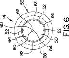
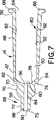
図5〜図7を参照して、ハウジング14は、概ね筒状の形状を有しており、医薬を所定の投与量投与することができるように構成されている。概ね筒状の形状であり比較的硬いプラスチックであることが好ましいが、他の形状及び材料を用途に応じて用いてもよい。ハウジング14はバレル部47を有しており、バレル部47はテーパー状内面52を介してハウジング部材50を形成する概ねテーパー状の筒状壁48を有している。ハウジング14は、さらに外表面54、近接端56、及び近接端56と反対側の遠方端58をさらに備えている。
【0020】
筒状壁48は、好ましくは上方端62によって形成される上方開口60と、下方端66によって形成される下方開口64の2つの開口を有していることが好ましい。2つの開口が好ましいが3つ以上であってもよい。好ましい実施例においては、上方開口60及び下方開口64は、縦方向に位置し、ハウジングチャンバー50と流通している。図6及び図7から明らかなように、下方開口64はハウジングチャンバー50よりも大きな内周面を有しており、ハウジングチャンバー50は上方開口60よりも大きな内周面を有している。このような配置によって、テーパー状の内面52が形成され、ハウジング14の自動的な充填操作を容易にし、プランジャー16の着座を容易にすることができる。
【0021】
下方端66の外表面54の上に形成され、そこから概ね径方向に延びる同心リング68が示されている。理想的には、同心リング68はハウジング14と一体化されており、プランジャー16に圧力を掛けたとき使用者が投薬アプリケーター10を確実に持つことがでるように使用されるものである。1つの同心リング68を示しているが、ハウジング14から延びかつハウジング14の周りに間隔を隔てて設けられる少なくとも2つの部材のような、その他の保持及び把持手段を用いてもよい。
【0022】
図5及び図7に示すように、遠方端58は、段階的なテーパー形状であり、ノズル69の終端に位置している。ノズル69は、係合部70と、目標部位の上に直接配置される緩やかに丸いチップ72を有している。好ましい実施例においては、バレル部47、係合部70及びチップ72は一体化しており、射出成型プロセスにおいて1つのピースとして形成される。しかしながら、これらのピースを別々に形成し、接着などにより共に結合させてもよい。また、図示するように、バレル部47は係合部70よりも大きな外周を有する上方端62においてショルダー74を形成しており、係合部70はチップ72より大きな外周を形成している。
【0023】
緩やかな丸い端部75を有するチップ72は、約4mmと約6mmの間の長さであり、好ましくは約5mmである。チップ72は、必要な目標部位の上または中に、直接配置されるものである。チップ72及びノズル69は、身体の表面に接触したときに傷や不快感を与えないように設計されており、処置の必要な正確な部位において身体部分の上または中に直接に医薬材料を容易にかつ正確に塗布することができる十分な長さを有している。
【0024】
ノズル69は、尿道、膣、耳、及び眼などのいくつかの体の部分の上または中に直接医薬を投与するのに適するものである。チップ72及びノズル69によって、これらの体の部分の中及び周りに容易にアクセスすることができ、一方ショルダー74によって、貫通を阻止し、その周りの組織に対する傷などが最小限になるようにしている。例えば、チップ72及びノズル69によって、耳へのアクセスが容易になり、ショルダー74によって、チップ72及びノズル69が安全な所定の深さを超えて耳に入り込むのを防止している。
【0025】
図示した実施例においては、係合部70は、(図5及び図7に示すように)第2の接触ポイントである少なくとも1つのリップ76を有しており、このリップ76は係合部70から径方向に外側に突き出ており、その外周面の周りに沿って延びている。1つのリップ76のみを図示しているが、複数のリップを設けてもよい。さらには、係合部70の外周面に沿って延びる1つのリップ76の代わりに、係合部の周りに間隔を隔てて形成される径方向の外側に延びた複数のノブを設けてもよい。
【0026】
対向する第1及び第2の端部86及び88を有する投薬チャンバーすなわち通路84は、ハウジング14内に形成されており、実質的にハウジングチャンバー50と同軸になるように形成され、第1の端部86は、上方開口60と流通している。従って、第2の端部88は少なくとも1つの投与開口90と流通している。
【0027】
1つの投薬チャンバー及び開口84及び90が図示されているが、薬剤及び用途に応じて、複数の開口及びチャンバー90及び84が設けられてもよい。また、投与開口及びチャンバー90及び84は、プラグ46の外周よりも僅かに大きい内周を有しており、これによってそれらの間に液体の強固なフリクションフィットが与えられている。キャップ12が適切にハウジング14の上に取り付けられると、プラグ46は投与開口及びチャンバー90及び84と取り外し可能に係合され、投与開口90を確実に閉めて漏れを防ぐ。投与開口90及びチャンバー84は同じ内周を有するように図示されているが、これらの関係は異なっていてもよい。例えば、投与チャンバーすなわち通路84は、投与開口90よりも大きな内周を有していてもよい。
【0028】
取り付け取り外し可能なキャップ12は、その上に形成された各接触ポイントによってハウジング14に取り付けられ、取り付け取り外し可能なキャップ12がハウジング14に取り付けられたとき気密なスナップフィットを形成するように働く。具体的には、キャップ12から内側に延びるリップ32が、係合部70から外側に延びるリップ76と取り外し可能に係合され、(図2に示すように)気密なスナップフィットを形成し、ハウジング14にキャップ12を確実に固定する。キャップ12をハウジング14に適切に配置し固定すると、下方端部22がショルダー74に当接し、キャップ12から医薬材料が漏れるのを防止する。
【0029】
接触ポイントに加えて、着座デバイス34もまた取り付け取り外し可能なキャップ12をハウジング14の上に適切に配置し固定するのに役立つ。少なくとも2つの対向する直立部材36の縦方向部42の間で測定した取り付け取り外し可能なキャップ12の内周は、チップ72の外周より僅かに大きく、これらの間で気密なフリクションフィットが形成される。傾斜したガイド部44は、取り付け取り外し可能なキャップ12の中でチップ72が適切に位置決めされるのに用いられ、縦方向部42はそれらの間で気密なフリクションフィットを与える。
【0030】
ハウジング14における丸いトップチャンバー78は、上方端62の内面52により形成されている。さらに、位置決めデバイス80は内面52の上に形成されており、位置決めデバイス80は、ハウジングチャンバー52内でプランジャー16の位置決めをし、さらに突発的にプランジャー16が抜けるのを防止している。具体的には、位置決めデバイス80は、下方端66から所定距離離れて、内面50に沿って部分的に形成された少なくとも1つのノブ82を有している。好ましい実施例において、位置決めデバイス80は、内面52から径方向内側に突出し内面と一体化された4つのノブ82を有している。この4つのノブ82は内面52の周面の周りで等間隔空けて形成され、ハウジングチャンバー50が医薬材料で満たされた後、プランジャー16を正確にかつ強固に配置する。
【0031】
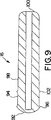
本発明の他の重要な特徴は、図8及び図9に詳細に示すように、ハウジング14内において軸方向に動くように設けられるプラットホーム16である。プランジャー16は、好ましくはポリオレフィンのような成形されたプラスチックから形成され、側面から見たときに概ね筒形状を有しており、キャップ12のように、末端から見たとき概ね丸い形状を有している。ハウジング14の形状に応じて、プランジャー16は他の形状であってもよい。プラットホーム16は好ましくは概ねドーム型の上面92を有しており、上面92はハウジング14内で医薬材料を支持し、上面92の周辺エッジ96から続くスカート94を有している。
【0032】
ハウジングチャンバー50には、自動的な充填プロセスによって医薬が充填される。このプロセスは、内面50をテーパーにすることにより容易になる。充填されたとき、投薬アプリケーター10は、プランジャー14の上面92をハウジングチャンバー50内に挿入することにより組み立てられ、ここで位置決めデバイス80はプランジャー14の位置を適切な位置にする。具体的にはプランジャー16は正確に位置決めされ、周辺エッジ96が複数のノブ82と取り外し可能に係合されることにより、強固な位置決めがなされる。
【0033】
組み立てたとき、ハウジングチャンバー50は、内面50、丸いドーム型の上面92、及びドーム型のトップチャンバー78によって区切られている。好ましい実施例において、周辺エッジ96はハウジング14の内面50によって摺動しながら案内され、ハウジング14内の所望の位置でプランジャー16が好ましくは十分な摩擦の係合により支持される。プランジャー16は、(図2に示すように)使用者が力を入れることにより、矢印Pで示す方向に丸いトップチャンバー78及び投与開口90に向かって滑りながら進むように構成されている。好ましくは、使用者の親指によって外周面98または概ね平坦な押圧端部100を押す。このようにして、医薬は投与チャンバーすなわち通路84及びノズル開口90を通り投与される。
【0034】
図2、図8及び図9において示す実施例は、少なくとも1つの同心リング102が周辺エッジ96から所定距離離れたプランジャー16上に設けられていることを示している。好ましい実施例においては、少なくとも1つの同心リング102がプランジャー16と一体的にかつ概ね径方向に延びるように設けられている。さらに、同心リング102を図示しているが、間隔を開けて設けた複数のリング102を設けてもよい。
【0035】
同心リング102は、多くの役割を果たす。このリング102は内面52と強固なフリクションフィットを形成し、かつこれによって摺動しながら案内する。この強固なフリクションフィットは、自動的な充填プロセスの際にプランジャー16を適切に着座させるように働き、ハウジング14が医薬で満たされたとき、ハウジング14の気密な一体性を保つようにする。
【0036】
さらに、同心リング102は、プランジャー16が突発的に抜け落ちるのを防止し、チャンバー50内の医薬が漏れるのを防止する。プランジャー16がハウジング14のハウジングチャンバー50内で適切に着座しているとき、同心リング102は内面52に形成されたノブ82と取り外し可能に係合する。このような取り外し可能な係合により、プランジャー16の適切な着座が確実になるだけでなく、プランジャー16がハウジング14から抜け落ちたり、医薬が漏れたりするのを防止することができる。
【0037】
図面から明らかなように、プランジャー16は、ドーム型の上面92及び周辺エッジ96を有しており、ハウジングチャンバー50内で強固にフィットし、内面52によって摺動しながら案内され、ハウジング14内でプランジャー16を支持する。この強固なフィットによって、ハウジングチャンバー50から医薬材料を本質的に完全に投与することができるようになる。周辺エッジ96及びドーム型上面92は、プランジャー16が進むと、内面52から医薬材料を掻き取る。さらに、プランジャー16が完全に押しつけられると、ドーム型上面92がドーム型トップチャンバー78の内側に完全にフィットする。このような配置により、プランジャー16が押し進んだとき、最大量の投与をすることができ、ハウジング14内に残った医薬材料は最小になる。
【0038】
アプリケーター10の目的は、医薬材料がプランジャー16を通り、使用者の手や、投薬アプリケーター10を用いていないときにこれを載せている棚またはその他の場所の上に漏れて出るのを防止することにある。このシーリングの係合は、好ましくは、ドーム型の上面92、周辺エッジ96及び、ハウジング14の内面52に気密なフリクションフィットを有する同心リング102によって達成される。
【0039】
ここで図2を参照して、本件アプリケーター10の動作の態様をより詳細に説明する。使用者はアプリケーター10、一般には同心リング68と隣接するハウジング14の周りを掴む。使用者が手動で概ね平坦な押圧端部100または外表面98をハウジング14の上端62に向かって(矢印Pの方向に)押しつけることにより、ドーム型の上面92に力が付与される。上面92は投与開口90を通り医薬を押し出し、これによって医薬材料の単一の所定投与量が投与される。1を超える投与量を投与する場合には、一連の適当なマーキングをハウジング14に施してもよい。
【0040】
必要であれば、アプリケーター10は1以上の投与量を収納してもよい。所望量の医薬材料を投与した後、使用者はプランジャー16を押しつけるのをやめる。
【0041】
ここで図2を参照して、取り付け取り外し可能なキャップ12はハウジング14を閉じた状態で示されている。取り付け取り外し可能なキャップ12はハウジング14と係合しており、上述のように気密な状態でチップ72を含むノズル69をカバーしているので、ハウジング14を閉じた、すなわち係合しているとき一定体積の空気が閉じ込められている。所望量の医薬材料を投与した後、使用者はハウジング14の上に取り付け取り外し可能なキャップ12を取り付ける。プランジャー16が上端62から退いて残った応力を緩和することができることに加えて、取り付け取り外し可能なキャップ12内に閉じ込められた一定体積の空気は投与開口90から下部開口64に向かって医薬材料及びプランジャー16を押し戻すように作用する。このキャップ12を用いることにより医薬材料の漏れのおそれを低減することができる。従って、望ましくない染み出しや漏れを防止することができる。
【0042】
本発明は、キャップ12、ハウジング14、及びプランジャー16の数、形状、角度、方向、結合及びまたは離間の方法において限定されるものではない。投薬アプリケーター10、すなわち取り付け取り外し可能なキャップ12、ハウジング14及びプランジャー16は、射出成型に適したポリオレフィン(例えば、ポリエチレン、ポリプロピレン)のような透明、半透明または不透明な樹脂の硬いプラスチック材料からその全てが形成されていることが好ましい。しかしながら、アプリケーター10を製造し組み立てる他の材料及び方法には、個々の部品を成型し、これらの部品を化学接着剤及び/または超音波溶接により組み立てるものも含まれる。
【0043】
本発明のディスペンサーの特定の実施例を図示して説明したが、クレームに述べられる発明を逸脱しない範囲において、当業者によって変更が加えられてもよい。
【図面の簡単な説明】
図1は、本発明に従う投薬コンテナであって、閉じた状態の取り付け取り外し可能なキャップ、着座しているが投与していない状態のプランジャーを示す正面図である。
図2は、着座しているが投与していない状態の投薬コンテナと閉じた状態の取り付け取り外し可能なキャップを示す横断面図である。
図3は、図1のキャップを示す端面図である。
図4は、図3の取り付け取り外し可能なキャップを示す横断面図である。
図5は、取り付け取り外し可能なキャップ及びプランジャーを外した状態の図1のハウジングを示す斜視図である。
図6は、図5のハウジングを示す端面図である。
図7は、図5のハウジングを示す横断面図である。
図8は、ハウジングから抜いた状態の図1のプランジャーを示す斜視図である。
図9は、図8のプランジャーを示す横断面図である。[0001]
BACKGROUND OF THE INVENTION
The present invention relates generally to container and applicator systems, and in particular, the present invention relates to a disposable dosing container (container) for administering a medicament to a target site.
[0002]
BACKGROUND OF THE INVENTION
Traditionally, collapsible tubes and bottles have been used to administer semi-solid drug substances, such as creams, ointments, gels, suspensions, solutions, colloids, ointments, etc., that are essentially non-flowable to the target site. Is actually used without a dispenser or with a dispenser. When the tube is used without a dispenser, the tube is squeezed by the user and the medicine is pushed out from the opening to the target site of the affected area, but the tube usually contacts the affected area at this time. If a bottle is used, the applicator or user's finger is placed in the medication before application. Repeated use of tubes or bottles makes them dirty and re-infects users. In addition, such tubes and bottles are commonly used for external use and are not suitable for use in the mouth, nose, ear, or vagina.
[0003]
Prior attempts to solve these problems include dispensers, typically collapsible tubes or tubes filled from bottles. The dispenser is generally tapered and has a shape for insertion into a body cavity. However, repeated use of non-disposable dispensers causes reinfection in the user. Furthermore, the collapsible tube or bottle and dispenser combination is bulky and cannot be easily discarded.
[0004]
Another way to avoid the problems disclosed by the prior art is a syringe. However, although such syringes can be easily used to administer medication to the body cavity, the problem of reinfection cannot be eliminated when reused. If the syringe is disposable, the problem of reinfection is eliminated, but the syringe is difficult to use for non-medical professionals and its use is timid. In addition, the syringe plunger is designed to be easily removable, which may result in loss of drug substance.
[0005]
The present invention solves the above problems and provides a device using a disposable applicator that does not cause leakage to administer a medicine to a target site.
[0006]
SUMMARY OF THE INVENTION
The present invention provides a dosage applicator suitable for the use of semi-solid medicaments such as creams, ointments, gels, suspensions, viscous solutions or colloidal suspensions, ointments and the like. In addition, the dosing applicator, whether a single unit dose or multiple doses, can easily and accurately administer medication over or within the body part of the target site to be treated. .
[0007]
Examples of uses of this medication applicator include administration of drugs to the urethra and urethra for male erectile dysfunction, direct application to the vagina and / or clitoris for female sexual dysfunction, vaccines or oral Examples include oral application of a care product, intranasal application of a vaccine or a drug, intraaural application, and application of a drug to the eye.
[0008]
The disposable applicator includes a substantially cylindrical hollow housing, a plunger, and a removable cap. The housing has opposing proximal and distal ends, a dispensing opening, and a tapered inner surface with a positioning device. The distal end is located at the tip of the dosing nozzle, which forms a dosing passage substantially coaxial with the housing. The plunger has a peripheral edge and is configured to move axially within the housing. The peripheral edge of the plunger is positioned by a positioning device, guided to slide along the inner surface, and supports the plunger in the housing.
[0009]
The removable cap is configured to engage and cover in a hermetic manner at the distal end of the housing. An airtight fit is preferably provided by the inner surface of the removable cap that engages the distal end of the housing with a strong friction fit. A plug provided on the inner surface of the cap removably engages and seals the dispensing opening, and a first lip on the cap is removably engaged with a lip on the housing.
[0010]
Many other advantages and features of the present invention will become readily apparent from the following detailed description and drawings.
[0011]
[Description of Preferred Embodiment]
Referring first to FIGS. 1 and 2, a dosing container or applicator embodying the present invention is shown substantially as 10 and includes a
[0012]
The dosing applicator 10, i.e., the
[0013]
The
[0014]
[0015]
In the preferred embodiment, the
[0016]
Returning to FIGS. 3 and 4, the
[0017]
Each
[0018]
3 and 4 further include at least one
[0019]
Referring to FIGS. 5 to 7, the
[0020]
The
[0021]
Shown is a
[0022]
As shown in FIGS. 5 and 7, the
[0023]
A
[0024]
The
[0025]
In the illustrated embodiment, the
[0026]
A dosing chamber or
[0027]
Although one dosing chamber and
[0028]
The
[0029]
In addition to the contact points, the
[0030]
A round
[0031]
Another important feature of the present invention is a
[0032]
The
[0033]
When assembled, the
[0034]
The embodiment shown in FIGS. 2, 8 and 9 shows that at least one
[0035]
The
[0036]
Furthermore, the
[0037]
As is apparent from the drawing, the
[0038]
The purpose of the applicator 10 is to prevent the medicinal material from leaking through the
[0039]
Here, with reference to FIG. 2, the operation | movement aspect of this application applicator 10 is demonstrated in detail. The user grasps the applicator 10, generally around the
[0040]
If necessary, the applicator 10 may contain one or more doses. After administering the desired amount of pharmaceutical material, the user stops pressing the
[0041]
Referring now to FIG. 2, the
[0042]
The present invention is not limited in the number, shape, angle, orientation, coupling and / or spacing methods of the
[0043]
While particular embodiments of the dispenser of the present invention have been illustrated and described, modifications may be made by those skilled in the art without departing from the invention described in the claims.
[Brief description of the drawings]
FIG. 1 is a front view of a dosing container according to the present invention showing a closed, removable cap, a plunger that is seated but not being dosed.
FIG. 2 is a cross-sectional view showing the medication container in a seated but not dispensed state and a cap that is removable in a closed state.
FIG. 3 is an end view showing the cap of FIG.
FIG. 4 is a cross-sectional view showing the removable cap of FIG.
FIG. 5 is a perspective view of the housing of FIG. 1 with the removable cap and plunger removed.
6 is an end view of the housing of FIG.
7 is a cross-sectional view showing the housing of FIG.
FIG. 8 is a perspective view showing the plunger of FIG. 1 in a state where it is removed from the housing.
FIG. 9 is a cross-sectional view showing the plunger of FIG.
Claims (5)
対向する近接端及び遠方端を有し、それらの間に延びるテーパー状の内面を有する実質的に筒状の中空のハウジングであり、前記遠方端は実質的にハウジングと同軸の投与通路を形成する投与ノズルの末端であり、前記内面は位置決めデバイスを有し、かつ前記内面には前記遠方端に隣接して丸いトップチャンバーが形成されているハウジングと、
ドーム型の遠方端及び周辺エッジを有し前記ハウジングの中で軸方向に移動可能に設けられているプランジャーであり、前記周辺エッジが前記位置決めデバイスにより位置決めされ、前記ハウジング内で前記プランジャーを支持するため前記内面により摺動して案内され、使用者の力が加えられることにより前記投与通路に向かって前記プランジャーが摺動して進み、前記ドーム型の遠方端が前記ハウジングの前記丸いトップチャンバーの内側にフィットするように構成されており、前記力が医薬を前記通路を通り押し出すように働くプランジャーと、
前記ハウジング内に収納される医薬とを備える投薬アプリケーター。A disposable applicator for administering a medicament and a medicament contained therein, the combination of
A substantially cylindrical hollow housing having opposing proximal and distal ends and a tapered inner surface extending therebetween, the distal end forming a dispensing passage substantially coaxial with the housing. A housing at the distal end of the dosing nozzle, wherein the inner surface has a positioning device , and the inner surface is formed with a round top chamber adjacent to the distal end ;
A plunger having a dome-shaped distal end and a peripheral edge, the plunger being axially movable in the housing, wherein the peripheral edge is positioned by the positioning device, and the plunger is positioned in the housing. is guided to slide by the interior surface for supporting said toward the administration passage by the force of the user is added and proceed to the plunger slides, said distal end of said domed said housing A plunger configured to fit inside a round top chamber, the force acting to push the medicament through the passageway;
A medication applicator comprising a medicament housed in the housing.
Applications Claiming Priority (3)
| Application Number | Priority Date | Filing Date | Title |
|---|---|---|---|
| US09/232,360 | 1999-01-15 | ||
| US09/232,360 US6224573B1 (en) | 1999-01-15 | 1999-01-15 | Medicament dispenser |
| PCT/US2000/001033 WO2000041748A1 (en) | 1999-01-15 | 2000-01-14 | Medicament dispenser |
Publications (2)
| Publication Number | Publication Date |
|---|---|
| JP2002534225A JP2002534225A (en) | 2002-10-15 |
| JP4319357B2 true JP4319357B2 (en) | 2009-08-26 |
Family
ID=22872796
Family Applications (1)
| Application Number | Title | Priority Date | Filing Date |
|---|---|---|---|
| JP2000593357A Expired - Lifetime JP4319357B2 (en) | 1999-01-15 | 2000-01-14 | Medication applicator |
Country Status (19)
| Country | Link |
|---|---|
| US (1) | US6224573B1 (en) |
| EP (1) | EP1152783B1 (en) |
| JP (1) | JP4319357B2 (en) |
| KR (1) | KR100763213B1 (en) |
| CN (1) | CN100366308C (en) |
| AT (1) | ATE448815T1 (en) |
| AU (1) | AU2507100A (en) |
| BR (1) | BR0007485B1 (en) |
| CA (1) | CA2359497C (en) |
| DE (1) | DE60043336D1 (en) |
| DK (1) | DK1152783T3 (en) |
| ES (1) | ES2336536T3 (en) |
| HK (1) | HK1044298B (en) |
| HU (1) | HU229895B1 (en) |
| IL (2) | IL143915A0 (en) |
| RS (1) | RS52140B (en) |
| TR (1) | TR200102013T2 (en) |
| WO (1) | WO2000041748A1 (en) |
| ZA (1) | ZA200105220B (en) |
Cited By (1)
| Publication number | Priority date | Publication date | Assignee | Title |
|---|---|---|---|---|
| JP2018527255A (en) * | 2015-09-04 | 2018-09-20 | エフ・ホフマン−ラ・ロシュ・アクチェンゲゼルシャフト | Adapter for connecting the dispenser to the container |
Families Citing this family (35)
| Publication number | Priority date | Publication date | Assignee | Title |
|---|---|---|---|---|
| US6693135B2 (en) * | 2000-01-10 | 2004-02-17 | Nexmed (Holdings) Incorporated | Prostaglandin compositions and methods of treatment for male erectile dysfunction |
| US20040002482A1 (en) * | 2000-08-30 | 2004-01-01 | Dudley Robert E. | Androgen pharmaceutical composition and method for treating depression |
| US6503894B1 (en) | 2000-08-30 | 2003-01-07 | Unimed Pharmaceuticals, Inc. | Pharmaceutical composition and method for treating hypogonadism |
| US6988675B2 (en) * | 2001-01-12 | 2006-01-24 | Johnson Diversey, Inc. | Multiple function dispenser |
| WO2002085429A2 (en) * | 2001-04-24 | 2002-10-31 | Comar | Child friendly syringe |
| US7591808B2 (en) * | 2003-01-16 | 2009-09-22 | Femmepharma Holding Company, Inc. | Vaginal or rectal applicator |
| US20040172738A1 (en) * | 2003-03-06 | 2004-09-09 | Erene Caine | Ear protector |
| US20040241244A1 (en) * | 2003-03-21 | 2004-12-02 | Nexmed (Holdings) Inc. | Neuronal growth enhancement by prostaglandin compositions and methods |
| US20040241243A1 (en) * | 2003-03-21 | 2004-12-02 | Nexmed (Holdings) Inc. | Angiogenesis promotion by prostaglandin compositions and methods |
| KR100574609B1 (en) * | 2003-11-28 | 2006-05-02 | 방지환 | Portable medicine liquid jet spraying and injecting device |
| CN101287470B (en) | 2005-10-12 | 2012-10-17 | 优尼麦德药物股份有限公司 | Improved testosterone gel and method of use |
| WO2007045901A1 (en) * | 2005-10-21 | 2007-04-26 | Nilufer Smith Innovations Limited | Improvements in and relating to disposable dispensers for personal use |
| US7666160B2 (en) * | 2006-12-29 | 2010-02-23 | Kimberly-Clark Worldwide, Inc. | Delivery device |
| US9005183B2 (en) * | 2007-05-16 | 2015-04-14 | Health Knight, Llc | System and method for treating erectile dysfunction |
| DE102007037565A1 (en) * | 2007-08-09 | 2009-02-12 | Mglas Ag | Syringe body and method for producing a syringe body |
| US20090062690A1 (en) * | 2007-08-29 | 2009-03-05 | Quaternion Investments Llc | Specimen Collecting |
| US8616213B2 (en) * | 2008-11-11 | 2013-12-31 | J3 Group, Llc | Earplug insertion device |
| TWI430762B (en) * | 2009-09-16 | 2014-03-21 | Colgate Palmolive Co | Oral care system, kit and method |
| CN102711554B (en) | 2009-12-23 | 2014-10-29 | 高露洁-棕榄公司 | Oral care system |
| KR101453632B1 (en) | 2009-12-23 | 2014-10-22 | 콜게이트-파아므올리브캄파니 | Oral care system |
| US9138046B2 (en) | 2009-12-23 | 2015-09-22 | Colgate-Palmolive Company | Oral care system, kit and method |
| BR112012015734A2 (en) | 2009-12-23 | 2017-03-14 | Colgate Palmolive Co | system, kit and method for oral care |
| US20110295211A1 (en) * | 2010-06-01 | 2011-12-01 | Yeager Don F | Applicator |
| EP2640445A4 (en) * | 2010-11-19 | 2016-06-01 | Bayer Consumer Care Ag | Click pen applicator device and method of using same |
| RU2597527C2 (en) | 2010-12-15 | 2016-09-10 | Колгейт-Палмолив Компани | Oral care set and dispensing device for such set (versions) |
| RU2599863C2 (en) * | 2011-03-25 | 2016-10-20 | Лео Фарма А/С | Applicator |
| CA2745320A1 (en) | 2011-07-06 | 2013-01-06 | Duoject Medical Systems Inc. | Reconstitution device |
| DE102011079908A1 (en) | 2011-07-27 | 2013-01-31 | Peter Lüpges | Portable tempering device for drugs |
| AU2013202778A1 (en) * | 2013-03-14 | 2014-10-02 | Gen-Probe Incorporated | Systems, methods, and apparatuses for performing automated reagent-based assays |
| AU2013202805B2 (en) | 2013-03-14 | 2015-07-16 | Gen-Probe Incorporated | System and method for extending the capabilities of a diagnostic analyzer |
| US20150164736A1 (en) * | 2013-12-16 | 2015-06-18 | Esther Gallant | Lubrication applicator for body lumen |
| AU2015381790B2 (en) | 2015-02-02 | 2018-10-04 | Colgate-Palmolive Company | Oral care system and oral care material dispenser |
| WO2018163201A1 (en) | 2017-03-06 | 2018-09-13 | All India Institute Of Medical Sciences (Aiims) | A device, method and kit for the reconstitution of a solid or semi solid pharmaceutical composition |
| US10857151B1 (en) * | 2020-02-21 | 2020-12-08 | Villya LLC | Treatment of female genital schistosomiasis |
| CN111467126B (en) * | 2020-03-12 | 2022-04-05 | 聊城市人民医院 | Auxiliary eye dropping device |
Family Cites Families (13)
| Publication number | Priority date | Publication date | Assignee | Title |
|---|---|---|---|---|
| US2518486A (en) | 1948-03-06 | 1950-08-15 | Ortho Pharma Corp | Single dose dispenser |
| US2516846A (en) | 1948-07-21 | 1950-08-01 | Cleveland Container Company | Applicator |
| US2925815A (en) | 1958-12-16 | 1960-02-23 | Celluplastic Corp | Applicator for dispensing tablet medicaments |
| US3559645A (en) * | 1968-07-01 | 1971-02-02 | Kathryn C Schaller | Disposable syringe |
| DE3266680D1 (en) | 1981-07-29 | 1985-11-07 | Duphar Int Res | Hypodermic syringe |
| JPH034282Y2 (en) * | 1986-09-16 | 1991-02-04 | ||
| ES2009497A6 (en) | 1987-11-27 | 1989-10-01 | Candela Estruch Miracle | Syringe for one sole use. |
| US5858000A (en) * | 1988-12-14 | 1999-01-12 | Inviro Medical Devices Ltd. | Safety syringe needle device with interchangeable and retractable needle platform |
| US5163907A (en) | 1991-06-24 | 1992-11-17 | Szuszkiewicz Christine M | Single use retractable needle syringe |
| ZA932947B (en) * | 1992-04-28 | 1993-10-27 | Schering Plough Healthcare | Applicator for semisolid medications |
| US5267962A (en) * | 1992-06-10 | 1993-12-07 | Jenson Robert W | Disposable hypodermic syringe with needle safe feature |
| DE4414019C1 (en) * | 1994-04-22 | 1995-02-09 | Henkel Kgaa | Refill cartridge for a pen which delivers product by running over a surface and method of filling the same |
| US5833382A (en) | 1996-08-19 | 1998-11-10 | Helene Curtis, Inc. | Push-up dispenser suitable for dilatant materials |
-
1999
- 1999-01-15 US US09/232,360 patent/US6224573B1/en not_active Expired - Lifetime
-
2000
- 2000-01-14 DE DE60043336T patent/DE60043336D1/en not_active Expired - Lifetime
- 2000-01-14 TR TR2001/02013T patent/TR200102013T2/en unknown
- 2000-01-14 HU HU0104901A patent/HU229895B1/en unknown
- 2000-01-14 AU AU25071/00A patent/AU2507100A/en not_active Abandoned
- 2000-01-14 DK DK00903301.0T patent/DK1152783T3/en active
- 2000-01-14 CA CA002359497A patent/CA2359497C/en not_active Expired - Lifetime
- 2000-01-14 WO PCT/US2000/001033 patent/WO2000041748A1/en active Application Filing
- 2000-01-14 IL IL14391500A patent/IL143915A0/en active IP Right Grant
- 2000-01-14 RS YU50801A patent/RS52140B/en unknown
- 2000-01-14 EP EP00903301A patent/EP1152783B1/en not_active Expired - Lifetime
- 2000-01-14 KR KR1020017008591A patent/KR100763213B1/en active IP Right Grant
- 2000-01-14 BR BRPI0007485-3A patent/BR0007485B1/en not_active IP Right Cessation
- 2000-01-14 CN CNB008027919A patent/CN100366308C/en not_active Expired - Lifetime
- 2000-01-14 AT AT00903301T patent/ATE448815T1/en active
- 2000-01-14 JP JP2000593357A patent/JP4319357B2/en not_active Expired - Lifetime
- 2000-01-14 ES ES00903301T patent/ES2336536T3/en not_active Expired - Lifetime
-
2001
- 2001-06-21 IL IL143915A patent/IL143915A/en not_active IP Right Cessation
- 2001-06-25 ZA ZA200105220A patent/ZA200105220B/en unknown
-
2002
- 2002-08-14 HK HK02105966.7A patent/HK1044298B/en not_active IP Right Cessation
Cited By (1)
| Publication number | Priority date | Publication date | Assignee | Title |
|---|---|---|---|---|
| JP2018527255A (en) * | 2015-09-04 | 2018-09-20 | エフ・ホフマン−ラ・ロシュ・アクチェンゲゼルシャフト | Adapter for connecting the dispenser to the container |
Also Published As
| Publication number | Publication date |
|---|---|
| KR100763213B1 (en) | 2007-10-08 |
| BR0007485B1 (en) | 2010-04-06 |
| CN1336831A (en) | 2002-02-20 |
| WO2000041748A1 (en) | 2000-07-20 |
| KR20010101406A (en) | 2001-11-14 |
| YU50801A (en) | 2003-02-28 |
| HU229895B1 (en) | 2014-11-28 |
| ZA200105220B (en) | 2003-03-25 |
| JP2002534225A (en) | 2002-10-15 |
| EP1152783A1 (en) | 2001-11-14 |
| RS52140B (en) | 2012-08-31 |
| IL143915A0 (en) | 2002-04-21 |
| DE60043336D1 (en) | 2009-12-31 |
| CN100366308C (en) | 2008-02-06 |
| HUP0104901A2 (en) | 2002-05-29 |
| US6224573B1 (en) | 2001-05-01 |
| TR200102013T2 (en) | 2001-10-22 |
| HUP0104901A3 (en) | 2002-11-28 |
| BR0007485A (en) | 2001-10-23 |
| AU2507100A (en) | 2000-08-01 |
| ES2336536T3 (en) | 2010-04-14 |
| HK1044298A1 (en) | 2002-10-18 |
| DK1152783T3 (en) | 2010-03-29 |
| CA2359497C (en) | 2008-04-15 |
| IL143915A (en) | 2006-12-31 |
| ATE448815T1 (en) | 2009-12-15 |
| CA2359497A1 (en) | 2000-07-20 |
| EP1152783A4 (en) | 2008-07-02 |
| HK1044298B (en) | 2008-11-21 |
| EP1152783B1 (en) | 2009-11-18 |
Similar Documents
| Publication | Publication Date | Title |
|---|---|---|
| JP4319357B2 (en) | Medication applicator | |
| US5531703A (en) | Applicator for semisolid medications | |
| US4235235A (en) | Syringe | |
| CA2279875C (en) | Applicator for semi-solid medications | |
| US8267609B2 (en) | Vial for delivering contents onto a substrate | |
| JPH05508569A (en) | liquid oral administration device | |
| KR20030028843A (en) | Adjustable dosage syringe | |
| JPS61288870A (en) | Disposable single drug dose coater | |
| US20080249462A1 (en) | Disposable Dispensers for Personal Use | |
| EP2301599B1 (en) | Portable ejection and injection device | |
| US20070225658A1 (en) | Unit Dose Delivery Systems | |
| US20210354152A1 (en) | Discharger, static piston and method of discharging | |
| US20200078572A1 (en) | Discharger and method of discharging | |
| US20210331856A1 (en) | Container, discharger and method of assembling a discharger | |
| MXPA99007222A (en) | Applicator for semi-solid medications | |
| ITTO20011083A1 (en) | DISPOSABLE VIALS FOR THE DISTRIBUTION AND ADMINISTRATION OF MEDICINAL PRODUCTS WITH PORTABLE INFUSION DEVICES. |
Legal Events
| Date | Code | Title | Description |
|---|---|---|---|
| A621 | Written request for application examination |
Free format text: JAPANESE INTERMEDIATE CODE: A621 Effective date: 20070105 |
|
| A131 | Notification of reasons for refusal |
Free format text: JAPANESE INTERMEDIATE CODE: A131 Effective date: 20080722 |
|
| A601 | Written request for extension of time |
Free format text: JAPANESE INTERMEDIATE CODE: A601 Effective date: 20081014 |
|
| A602 | Written permission of extension of time |
Free format text: JAPANESE INTERMEDIATE CODE: A602 Effective date: 20081021 |
|
| A521 | Request for written amendment filed |
Free format text: JAPANESE INTERMEDIATE CODE: A523 Effective date: 20090121 |
|
| TRDD | Decision of grant or rejection written | ||
| A01 | Written decision to grant a patent or to grant a registration (utility model) |
Free format text: JAPANESE INTERMEDIATE CODE: A01 Effective date: 20090512 |
|
| A01 | Written decision to grant a patent or to grant a registration (utility model) |
Free format text: JAPANESE INTERMEDIATE CODE: A01 |
|
| A61 | First payment of annual fees (during grant procedure) |
Free format text: JAPANESE INTERMEDIATE CODE: A61 Effective date: 20090528 |
|
| FPAY | Renewal fee payment (event date is renewal date of database) |
Free format text: PAYMENT UNTIL: 20120605 Year of fee payment: 3 |
|
| R150 | Certificate of patent or registration of utility model |
Free format text: JAPANESE INTERMEDIATE CODE: R150 Ref document number: 4319357 Country of ref document: JP Free format text: JAPANESE INTERMEDIATE CODE: R150 |
|
| FPAY | Renewal fee payment (event date is renewal date of database) |
Free format text: PAYMENT UNTIL: 20130605 Year of fee payment: 4 |
|
| R250 | Receipt of annual fees |
Free format text: JAPANESE INTERMEDIATE CODE: R250 |
|
| R250 | Receipt of annual fees |
Free format text: JAPANESE INTERMEDIATE CODE: R250 |
|
| R250 | Receipt of annual fees |
Free format text: JAPANESE INTERMEDIATE CODE: R250 |
|
| R250 | Receipt of annual fees |
Free format text: JAPANESE INTERMEDIATE CODE: R250 |
|
| R250 | Receipt of annual fees |
Free format text: JAPANESE INTERMEDIATE CODE: R250 |
|
| R250 | Receipt of annual fees |
Free format text: JAPANESE INTERMEDIATE CODE: R250 |
|
| S111 | Request for change of ownership or part of ownership |
Free format text: JAPANESE INTERMEDIATE CODE: R313113 |
|
| S531 | Written request for registration of change of domicile |
Free format text: JAPANESE INTERMEDIATE CODE: R313531 |
|
| R350 | Written notification of registration of transfer |
Free format text: JAPANESE INTERMEDIATE CODE: R350 |
|
| R250 | Receipt of annual fees |
Free format text: JAPANESE INTERMEDIATE CODE: R250 |
|
| R250 | Receipt of annual fees |
Free format text: JAPANESE INTERMEDIATE CODE: R250 |
|
| EXPY | Cancellation because of completion of term |