JP4314036B2 - Image forming apparatus and image forming apparatus control method - Google Patents
Image forming apparatus and image forming apparatus control method Download PDFInfo
- Publication number
- JP4314036B2 JP4314036B2 JP2003008575A JP2003008575A JP4314036B2 JP 4314036 B2 JP4314036 B2 JP 4314036B2 JP 2003008575 A JP2003008575 A JP 2003008575A JP 2003008575 A JP2003008575 A JP 2003008575A JP 4314036 B2 JP4314036 B2 JP 4314036B2
- Authority
- JP
- Japan
- Prior art keywords
- cartridge
- image forming
- developing
- toner
- forming apparatus
- Prior art date
- Legal status (The legal status is an assumption and is not a legal conclusion. Google has not performed a legal analysis and makes no representation as to the accuracy of the status listed.)
- Expired - Fee Related
Links
- 238000000034 method Methods 0.000 title description 64
- 238000003860 storage Methods 0.000 claims description 81
- 230000015654 memory Effects 0.000 claims description 23
- 238000012546 transfer Methods 0.000 description 74
- 238000011161 development Methods 0.000 description 39
- 230000008569 process Effects 0.000 description 36
- 238000004891 communication Methods 0.000 description 14
- 239000000463 material Substances 0.000 description 14
- 238000010586 diagram Methods 0.000 description 13
- 238000004140 cleaning Methods 0.000 description 9
- 229920001971 elastomer Polymers 0.000 description 9
- 238000001514 detection method Methods 0.000 description 8
- 230000000694 effects Effects 0.000 description 8
- 239000005060 rubber Substances 0.000 description 8
- 239000003086 colorant Substances 0.000 description 7
- 230000015572 biosynthetic process Effects 0.000 description 6
- 239000010410 layer Substances 0.000 description 6
- 230000002093 peripheral effect Effects 0.000 description 6
- 230000001105 regulatory effect Effects 0.000 description 5
- 229920000459 Nitrile rubber Polymers 0.000 description 4
- 230000006870 function Effects 0.000 description 4
- 238000009434 installation Methods 0.000 description 4
- 230000002265 prevention Effects 0.000 description 4
- 238000011109 contamination Methods 0.000 description 3
- 230000008878 coupling Effects 0.000 description 3
- 238000010168 coupling process Methods 0.000 description 3
- 238000005859 coupling reaction Methods 0.000 description 3
- 229920005989 resin Polymers 0.000 description 3
- 239000011347 resin Substances 0.000 description 3
- 229920006311 Urethane elastomer Polymers 0.000 description 2
- 230000001276 controlling effect Effects 0.000 description 2
- 239000000428 dust Substances 0.000 description 2
- 239000004973 liquid crystal related substance Substances 0.000 description 2
- 239000002184 metal Substances 0.000 description 2
- 229910052751 metal Inorganic materials 0.000 description 2
- 238000003825 pressing Methods 0.000 description 2
- 238000012545 processing Methods 0.000 description 2
- 229920002379 silicone rubber Polymers 0.000 description 2
- 239000004945 silicone rubber Substances 0.000 description 2
- 238000003756 stirring Methods 0.000 description 2
- 229920000178 Acrylic resin Polymers 0.000 description 1
- 239000004925 Acrylic resin Substances 0.000 description 1
- 229910000906 Bronze Inorganic materials 0.000 description 1
- YCKRFDGAMUMZLT-UHFFFAOYSA-N Fluorine atom Chemical compound [F] YCKRFDGAMUMZLT-UHFFFAOYSA-N 0.000 description 1
- 244000043261 Hevea brasiliensis Species 0.000 description 1
- OAICVXFJPJFONN-UHFFFAOYSA-N Phosphorus Chemical compound [P] OAICVXFJPJFONN-UHFFFAOYSA-N 0.000 description 1
- 239000004952 Polyamide Substances 0.000 description 1
- 229920000800 acrylic rubber Polymers 0.000 description 1
- 230000005540 biological transmission Effects 0.000 description 1
- 239000010974 bronze Substances 0.000 description 1
- 229920005549 butyl rubber Polymers 0.000 description 1
- 239000011247 coating layer Substances 0.000 description 1
- 238000012790 confirmation Methods 0.000 description 1
- KUNSUQLRTQLHQQ-UHFFFAOYSA-N copper tin Chemical compound [Cu].[Sn] KUNSUQLRTQLHQQ-UHFFFAOYSA-N 0.000 description 1
- 239000000806 elastomer Substances 0.000 description 1
- 229910052731 fluorine Inorganic materials 0.000 description 1
- 239000011737 fluorine Substances 0.000 description 1
- 238000005470 impregnation Methods 0.000 description 1
- 230000009191 jumping Effects 0.000 description 1
- 238000010030 laminating Methods 0.000 description 1
- 238000004519 manufacturing process Methods 0.000 description 1
- 238000012986 modification Methods 0.000 description 1
- 230000004048 modification Effects 0.000 description 1
- 229920003052 natural elastomer Polymers 0.000 description 1
- 229920001194 natural rubber Polymers 0.000 description 1
- 230000003287 optical effect Effects 0.000 description 1
- 229920000058 polyacrylate Polymers 0.000 description 1
- 229920002647 polyamide Polymers 0.000 description 1
- 229920006122 polyamide resin Polymers 0.000 description 1
- 230000004044 response Effects 0.000 description 1
- 230000000717 retained effect Effects 0.000 description 1
- 229910052702 rhenium Inorganic materials 0.000 description 1
- 229910052703 rhodium Inorganic materials 0.000 description 1
- 229920002050 silicone resin Polymers 0.000 description 1
- 239000002356 single layer Substances 0.000 description 1
- 239000002344 surface layer Substances 0.000 description 1
- 229920002803 thermoplastic polyurethane Polymers 0.000 description 1
Images


Description
【0001】
【発明の属する技術分野】
本発明は、例えば複写機あるいはレーザプリンタ等の電子写真記録方式を利用する画像形成装置に於いて、特に、カラー画像形成装置の本体において、着脱自在に構成され、画像形成部の少なくとも1つの構成要素を備えたカートリッジを複数有する画像形成装置と、その画像形成装置の制御方法に関するものである。
【従来の技術】
従来におけるカラー画像形成装置として、複数の現像剤収容カートリッジを着脱可能な画像形成装置が知られている。図9は、従来から知られている複数の現像剤収容カートリッジを着脱可能に回転可能に保持するロータリ方式の画像形成装置である。この方式では、カートリッジ保持部が、何れか1つの現像剤収容カートリッジを画像形成位置に配置して画像形成を行なう。
【0002】
図9のロータリ方式のカラープリンタでは、像担持体である感光ドラム10は、不図示の駆動手段によって図示矢印方向に駆動され、一次帯電器20により一様に帯電される。次いで、露光装置30よりイエローの画像模様に従ったレーザ光Lが、感光ドラム10に照射され、感光ドラム10上に潜像が形成される。更に感光ドラム10が矢印方向に進むと回転支持体110により支持されたプロセスカートリッジ40a,b,c,dのうち、例えばイエロートナーが入ったカートリッジ40aが、感光ドラム10に対向するよう回転する。そして、感光ドラム1上の静電潜像が、選択されたプロセスカートリッジ40aのイエロートナーによって可視化される。中間転写ベルト50は感光ドラム10と略同速で矢印方向に回転しており、感光ドラム10上に形成担持されたトナー画像を一次転写ローラ80aに印加される1次転写バイアスによって、中間転写ベルト50の外周面に一次転写する。以上の行程をイエロー色、マゼンタ色、シアン色、黒色について行うことによって中間転写ベルト50上には複数色のトナー像が形成される。次に、所定のタイミングで転写材カセット120内からピックアップローラー130によって転写材が給紙される。同時に二次転写ローラ80bに二次転写バイアスが印加され中間転写ベルト50から転写材へトナー画像が転写される。
【0003】
更に転写材は、搬送ベルト140によって定着装置60まで搬送され溶融固着されることによりカラー画像が得られる。また、中間転写ベルト5上の転写残トナーは中間転写クリーニングローラ150により電荷が付与され、次回の一次転写時に感光ドラム上に逆転写される。一方、感光ドラム1上の転写残トナーはクリーニング装置70によって清掃される。
【0004】
ここで、プロセスカートリッジ40a,b,c,dは、トナーと現像ローラ、現像ブレード等とが一体化したものであり、プリンタ本体に対して着脱可能となっている。また、各々のプロセスカートリッジには、プロセスカートリッジに関する情報等が記憶される不揮発性の記憶部としてのNV(Non Volatile)RAM41a,b,c,dがカートリッジ側面に設けられている。また、読み出し/書き込み手段42は、これらのNVRAM41a,b,c,dが感光ドラム1に対向した位置P0においてそのNVRAM41a,b,c,dに対向または接触する位置に設けられている。そして、電源投入時や所定枚数プリント後等のタイミングで、NVRAMに記憶された情報の読み出し/書き込みが行われ、その情報に応じて像形成条件を変更したり、トナー残量や寿命等をユーザーに知らせている。
【0005】
【発明が解決しようとする課題】
しかし、このような画像形成位置(現像位置)でNVRAMにアクセスを行なう場合には、トナーの飛散や、現像電圧の影響を受けやすく、正確にデータ通信を行なえない可能性が生じる。
【0006】
すなわち、ロータリ方式の画像形成装置においては、現像剤収容カートリッジに、不揮発性メモリなどの記憶部を設け、カートリッジの寿命などを管理しようとした場合、画像形成位置(現像位置)でその記憶部にアクセスしようとすると、飛散した現像剤や現像電圧の電気ノイズの影響などを受けて、正確に通信が行えない可能性が生じる。
【0007】
本発明の目的は、カラー画像形成装置において、着脱自在に構成され、画像形成部の少なくとも1つの構成要素を備えたカートリッジを複数有する画像形成装置を改良することにある。
【0008】
さらに本発明の他の目的は、画像形成部の少なくとも1つの構成要素を備えたカートリッジに設けられた記憶部に対するアクセスを正確に行うことのできる画像形成装置及びその制御方法を提供することにある。
【0009】
さらに本発明の他の目的は、複数の画像形成部の少なくとも1つの構成要素備えたカートリッジを装着可能な画像形成装置において、寿命となった現像剤収容カートリッジを即座に交換可能とする画像形成装置及び画像形成装置の制御方法を提供することにある。
【0010】
【課題を解決するための手段】
本発明に係る画像形成装置は、記憶手段を有する現像剤収容カートリッジと、
前記現像剤収容カートリッジを複数保持可能で、画像形成するために回転移動可能なカートリッジ保持手段と、
前記記憶手段にアクセスするアクセス手段と、を有し、
前記カートリッジ保持手段は、前記現像剤収容カートリッジを着脱するときに、前記現像剤収容カートリッジを着脱可能な着脱位置に回転移動し、
前記アクセス手段は、前記カートリッジ保持手段に保持された複数の現像剤収容カートリッジのうち、前記着脱位置にある前記現像剤収容カートリッジの記憶手段にアクセスすることを特徴とする。
【0014】
【発明の実施の形態】
以下、本発明に係る画像形成装置を図面に則して更に詳しく説明する。
【0015】
<第1実施形態>
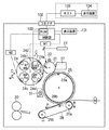
本発明にかかる第1実施形態について図1、図2、図3を参照して説明する。図1は、本実施形態に係る画像形成装置を説明する構成図である。画像形成装置は、パーソナルコンピュータやワークステーション等のホスト103とコネクタ102により電気的に接続されており、そのホスト103からのプリント要求信号に応じてビデオインターフェイスを介して画像データを受け取る。この画像データを基にイェローY、シアンC、マゼンタM、ブラックBkの4色に分解した画像データにより順次各色のトナー像を形成し、それらを中間転写体上に重ね合わせて紙などの転写材に一括転写してフルカラー画像を得るロータリ方式のカラープリンタである。
【0016】
図1において、21は静電像担持体としての光導電性の有機感光体ドラムであり、矢印Aの方向に回転駆動される。この感光体ドラム21の表面は、接触帯電手段としての帯電ローラ22の芯金にバイアスを印加することによって、所定の暗部電位に一様に帯電される。次に、第1色目(Y)の画像データに応じて、露光手段23によりON/OFF制御されたレーザビームにより走査露光が施され、明部電位として第1の静電潜像が形成される。このように形成された静電潜像は、回転自在な保持体であるロータリ24内に装着されている現像手段である各色の現像装置により現像、可視化される。このロータリは、第1色目のトナーとしてYトナーが内包された第1の現像装置24a、第2色目のトナーとしてMトナーが内包された第2の現像装置24b、第3色目のトナーとしてCトナーが内包された第3の現像装置24c、第4色目のトナーとしてBkトナーが内包された第4の現像装置24dを一体化した構成となっており、それぞれの色の画像形成時に感光ドラム対向位置に(矢印Bの方向に)駆動部であるモータM1によって回転移動され、所定の層厚に規制されたトナーを担持しているスリーブが回転駆動され、そのスリーブの芯金に所定のバイアスが印加されることにより現像を行う。また、Y、M、C、Bkの各現像手段24a、24b、24c、24dはそれぞれ一つのプロセスカートリッジ(現像カートリッジ)として、その消耗度合いにより別々に交換可能となっている。
【0017】
まず上述の第1の静電潜像は、第1色目のトナーとしてYトナーが内包された第1の現像カートリッジ24aにより現像、可視化される。現像方法としては、接触/非接触を問わず用いることができるが、本実施形態ではイメージ露光と反転現像とを組み合わせた非磁性1成分トナーによる接触現像法を用いている。この可視化された第1色目のトナー像は、第2の像担持体としての中間転写体25とのニップ部である第1の転写部位26aにおいて、シリンダー上に導電弾性層と離型性を有する表層とから形成された中間転写体25の表面に静電転写(1次転写)される。中間転写体25は、通紙可能な最大転写材の長さよりも長い周長を有し、前述の感光ドラム21に対して所定の押圧力をもって圧接されつつ、感光ドラムの周速度と略等速の周速度をもって感光ドラム21の回転方向に対して逆方向(各々図3の矢印の方向で、接触部位では同方向)に回転駆動される。そして、前記のように感光ドラム21の表面に形成されたトナー像は、中間転写体25のシリンダー部に対してトナーの帯電極性とは逆極性の電圧(1次転写バイアス)が印加されることにより、中間転写体25表面に静電転写(1次転写)される。
【0018】
尚、1次転写が終了した感光ドラム21表面に残留するトナーは、クリーニング装置27によって除去され、次の潜像形成に備える。残留トナーのクリーニングの詳細については後述する。
【0019】
引き続き同様な工程を繰り返し、その都度、Mトナーにより現像された第2色目のトナー像、Cトナーにより現像された第3色目のトナー像、Bkトナーにより現像された第4色目のトナー像が順次中間転写体25表面に転写、積層されることによりカラートナー像が形成される。その後、中間転写体25表面に対して離間状態にあった転写ベルト28が所定の押圧力をもって中間転写体25表面に圧接、駆動回転される。転写ベルト28は、転写ローラ29a及びテンションローラ29bによって支持され、前記転写ローラ29aに対しては、トナーの帯電極性とは逆極性の電圧(2次転写バイアス)が印加されることにより、第2の転写部位26bに所定のタイミングで搬送されてくる転写材P表面に、中間転写体25表面に積層されているカラートナー像が一括転写(2次転写)され、この転写材Pは定着装置30へと搬送され、永久画像として定着された後機外へと排出され、所望のカラープリント画像が得られる。
【0020】
また、2次転写が終了した中間転写体25表面に残存するトナーは、所定のタイミングで中間転写体25表面に対して当接状態となる中間転写体クリーニング装置31により除去される。
【0021】
現像カートリッジを着脱可能に保持するロータリ24は、図1に示されている矢印D、Eの方向に移動する構成となっており、画像形成を行わない状態では、ロータリ24は矢印E方向に移動している状態で停止している。この場合、現像カートリッジが着脱位置に停止しており、現像ローラがドラム21に当接しないように構成している。上述のような画像形成動作を行う場合、まず、ホスト103からの指示により画像形成動作が開始される。画像形成を行う前にロータリ24が回転し、現像カートリッジの現像ローラがドラムと当接する画像形成位置(現像位置)に来ると、ロータリ24が矢印のD方向に動作して現像動作が行われて画像形成が行われる。次の現像カートリッジでの現像に移行する場合には、ロータリは矢印E方向に移動して回転駆動され、次の現像カートリッジが現像位置に来るとロータリは再び矢印D方向に移動されて現像動作が行われる。矢印D、E方向への移動については後述するが、制御部100から指示信号をモータM2に送信することによりモータM2を駆動させることによって行われる。
【0022】
ロータリ24を矢印D、Eの方向に移動する構成は、図12に示すように、ロータリ上部に設けられた軸Jを支点として矢印D、Eの方向に移動可能な構成となっている。移動はロータリの枠体Wに設けられたプレートLを押す結合カム(CAM)が設けられており、制御部100からの指示信号がモータM2に送信され、指示信号に基づいて駆動部であるモータM2によって結合カム(CAM)を矢印方向に回転させてプレートLを押すことよってロータリ24を矢印D,E方向に移動可能としている。
【0023】
なお、図中の24a、24b、24c、24dは現像カートリッジであり、21は感光体ドラムである。
【0024】
図2は、本実施形態にかかる現像手段であるY、M、C、Bk各色のトナーをそれぞれ内包する現像カートリッジ24a、24b、24c、24dを示す構成図であり、この現像カートリッジ24a〜24dは、図1に示した画像形成装置であるロータリ方式のカラープリンタに着脱可能な構成である。図1中では、取り出し位置にあるイェロー用のY現像カートリッジ24aを上方の矢印C方向に取り出すことができる。図1に示すロータリ方式のカラープリンタに於いては、取り出し位置にて現像カートリッジの着脱を行う必要があり、同図中のY現像カートリッジ24a以外のM、C、Bk現像カートリッジである24b、24C、24dを交換する際には、現像カートリッジが保持されているロータリを回転させて取り出したいカートリッジを取り出し位置(図中24aの位置)に回転させる必要がある。
【0025】
以下、説明を簡略化する為、Yトナーの現像カートリッジ24aを対象とした場合を説明するが、他色の現像カートリッジについても同様である。
【0026】
図2に示す本実施形態の現像カートリッジ24aは、現像剤として非磁性一成分のイェロー(Y)トナーをトナー収容容器32a内に収容する反転現像装置である。この現像カートリッジ24aは、感光ドラム21に接触して図2中の矢印D方向に回転しながら現像を行う現像ローラ33aと、この現像ローラ33aにトナーを図中E方向に回転することによって供給するトナー供給手段としての供給ローラ34aと、現像ローラ33a上のトナー塗布量及び帯電量を規制するトナー規制手段としての現像ブレード35a、及びトナーを供給ローラ34aに供給すると共に撹拌する撹拌部材36a等からなる。
【0027】
本実施形態では剛体である感光ドラム21に対して接触して現像を行う構成を採るため、上記の現像ローラ33aは芯金上に弾性層を有することが望ましい。該弾性層としてはシリコーンゴムを用いたが、弾性層に使用するゴムとしては、その他NBRゴム(NBR:ニトリルゴム)、ブチルゴム、天然ゴム 、アクリルゴム、ヒドリンゴム、ウレタンゴム等、一般的に用いられるゴムが使用可能である。通常、上記ゴム材料のオイル含浸量を多くすることで、低硬度化が図られる。
【0028】
この現像ローラ33aを単層とし、トナーへの帯電付与性の観点から、負帯電性トナーを用いた場合には、ウレタンゴム、シリコーンゴム、NBRゴム等が好適に用いられる。また、正帯電性トナーを使用するのであれば、フッ素ゴム等が好適に用いられる。
【0029】
更に、弾性層外周にトナーへの帯電を考慮してコート層を設ける場合には、ポリアミド樹脂、ウレタン樹脂、シリコーン樹脂、アクリル樹脂、フッ素樹脂若しくは、これらを混合した樹脂等が好適に用いられる。
【0030】
また、現像ブレード35aとしては、現像ローラ33aとの当接部が金属又はゴム及び樹脂部材からなる公知のトナー規制部材が使用可能である。本実施形態では、燐青銅製の薄板にポリアミドエラストマーからなる樹脂部材を成形したものであり、これを現像ローラ33aに当接させている。
【0031】
攪拌部材36aにより攪拌されたトナーが図2に示す矢印D方向に回転する現像ローラ33aと、 矢印E方向に回転する供給ローラ34aとの摺擦によって現像ローラ33a上に供給される。現像ローラ33a上のトナーは現像ブレード35aによって所望の帯電量が付与されると共に、トナー量が規制され、現像ローラ33a上に所定量のトナーが担持される。
【0032】
この現像ローラ33a上に担持されたトナーは、現像時にロータリが回転し感光ドラム21と接触する部位、即ち現像部位に到達すると、現像ローラ33aの芯金に現像バイアスが印加されることで、感光ドラム21周面に形成された静電潜像が、現像ローラ33aの表面に担持されているトナーで反転現像されてトナー像として可視化される。
【0033】
尚、本発明にかかる実施形態において、画像形成装置は、上述の接触現像方式に限られるわけではなく、現像方式によらず用いることが可能であり、公知の非接触現像方式(ジャンピング現像等)を用いても構わない。
【0034】
次に、本実施形態のイェローY、マゼンタM、シアンC、ブラックBkの現像カートリッジ24a、24b、24c、24dに設けてある記憶部Re、Rf、Rg、Rhについて記述する。
【0035】
記憶部Re〜Rhは、本体の読み出し/書き込み部242と通信してデータの読み書きを行う構成となっている。この方式はアンテナ(図示せず)を用いた電磁結合方式の無線通信方式であり、記憶部Re〜Rhに対して非接触でデータを読み出したり書き込んだりすることが可能となっている。電磁波によって通信するため、ホコリやトナーなどで汚れた場合でもその影響を受けることなく正確に通信可能である。
【0036】
この記憶部Re〜Rhがそれぞれのカートリッジの容器側面に設けられている。各記憶部Re〜Rhには、それぞれのカートリッジの現像手段に内包されているトナーの色情報などのデータが予め記憶させてある。図1中のカートリッジ着脱位置にて、記憶部は、その記憶部であるメモリに対向配置されている画像形成装置の本体内部に設けられている読み出し/書き込み部242を介してメモリのデータを画像形成装置の制御部100に送受信可能とする。画像形成装置における制御部100は、読み出し/書き込み部242を介して受信した情報に基づき、現像カートリッジに内包されているトナーの色を識別したり、カートリッジの寿命を判断することが可能となる。
【0037】
図1に於いては、Y現像カートリッジ24aの位置にある場合に、記憶部Reに記憶されている情報を装置本体の制御部100で読み出すことが可能である。つまり、他の記憶部Rf〜Rhの情報を制御部100により読み書き可能とするには、それぞれのカートリッジを着脱位置までロータリを回転させて移動させる必要がある。なお、非接触方式に限らず、記憶部Re〜Rhとして画像形成装置本体と接触させて通信を行う接触式のメモリを用いることも可能である。
【0038】
なお、記憶部に記憶される情報としては、図10に示すような情報が記憶されている。
【0039】
例えばY現像カートリッジ24aの場合は、記憶部にはY現像カートリッジ内のトナーの色情報のほかに、Y現像カートリッジの製造時に付与されるシリアルナンバー、Y現像カートリッジを用いて画像形成を行ったページカウント数、Y現像カートリッジ内のトナーの残量、Y現像カートリッジの現像ローラ(図2の33a)の総回転時間、また、それらから計算されるカートリッジ寿命情報、カートリッジが寿命であることを示す情報などが記憶されている。M現像カートリッジ,C現像カートリッジ,K現像カートリッジの記憶部にもY現像カートリッジの記憶部と同様の情報が記憶されている。
【0040】
ここで、現像カートリッジ24a〜24dを最初に本体に装着する使用開始時の工程について説明する。
【0041】
画像形成装置本体にはY、M、C、Bkの各トナーを内包した現像カートリッジ24a〜24dが色毎に予め決められているロータリの装着個所に順次装着されることになる。
【0042】
画像形成装置の制御部100は、現像カートリッジ24a〜24dが本体に装着されていない場合には、先ずYの現像カートリッジ24aが装着されるロータリの部位が、カートリッジ着脱位置にくるようにロータリを回転させる。
【0043】
次に、ユーザにより画像形成装置の不図示の現像カートリッジ交換用カバーが開けられ、ロータリ内に現像カートリッジが装着され、再び交換カバーが閉じられたことを検知すると、本画像形成装置の制御部100はそのカートリッジの記憶部に書き込まれている色の情報を読み出すことで、現在装着されているカートリッジに内包されている色が何であるかを識別することができる。この現像カートリッジに書き込まれている色がイェロー(Y)であった場合には、即ち、記憶部に書き込まれている色の情報と装着個所の画像形成部の色とが合致した場合には、次のロータリの装着個所であるMの画像形成部のカートリッジ24bが着脱可能な位置にくるようにロータリを回転させる。
【0044】
ここで、本実施形態では、画像形成位置(現像位置)ではなく、カートリッジの着脱位置において記憶部であるメモリのデータを制御部100で読み出すことを可能な構成とすることを特徴としている。すなわち、画像形成位置(現像位置)以外の位置でメモリとアクセスできるため、現像財の飛散や現像電圧による電気ノイズの影響を受けることなくデータを読み出すことを可能としている。
【0045】
また、ユーザが誤って異なる色のカートリッジを装着した場合でも、直ぐにこれを検出することを可能としている。
【0046】
つまり、着脱位置で読み出す構成であるため、着脱位置とは異なる部位でメモリにアクセスする構成とした場合に発生する、メモリにアクセスするためにロータリを回転させる時間や、さらに誤装着の場合には着脱位置まで戻すための時間など、ユーザが誤って装着したことを報知するまでに多くの時間を費やしてしまうということも無くすことができる。
【0047】
上記と同様な手順により、他の色に対する現像カートリッジ24b、24c、24dを順次装着し、その現像カートリッジ24b、24c、24dがロータリ内の所定の画像形成部の装着個所に装着されていることが確認された後、制御部100はホスト103からのプリント要求が有ればいつでも画像形成動作が開始できるレディ(Ready)状態にする。
【0048】
次に、通常使用時における現像カートリッジ誤装着防止のための制御について説明する。
【0049】
記憶部Re〜Rhに書き込まれた色の情報を、現像カートリッジ24a〜24dの抜差しが行われる可能性のある所定のタイミング、即ち現像カートリッジ24a〜24dが取り出されたことを検出した際や本体の電源スイッチをオンした際等のタイミングで制御部100が読み出し、現在、装着されているロータリの画像形成部の色とメモリに書き込まれている色の情報とが合致していることを、制御部100が上述の様にロータリをカートリッジの取り出し位置に回転させて順次確認し、全てのロータリの画像形成部に正しく現像カートリッジが装着されていることを確認後に画像形成動作を開始可能する。
【0050】
また、装着された現像カートリッジの記憶部から読み出した色情報とロータリの画像形成部の色が合致しない場合には、制御部100は画像形成装置を動作させず、画像形成装置の液晶ディスプレイ等の表示装置104に現像カートリッジの装着箇所が間違っている旨の警告を出すようにすることも可能である。警告としては、警告文を表示しても良いし、LED等を点灯/点滅させても良く、装着個所が間違っている旨をユーザに報知する警告を出すようにすればよい。
【0051】
図3は、電源ON時などの画像形成装置のイニシャル時などの所定のタイミングで、現像カートリッジの装着個所の判断を具体的に示すフローチャートである。同図を用いて判定手順を更に詳細に説明する。
【0052】
先ず、待機状態にあるカラープリンタ本体のロータリ内のY画像形成部位に現像カートリッジが装着されたことを検知すると(S11−YES)、処理をステップS12に進め、制御部100は記憶部に書き込まれているトナーの色情報を読み出す(S12)。制御部100は、現像カートリッジが正しく装着されたか、即ち、Yの画像形成部に現像カートリッジ24aが装着されているか(Y=24a)を判断し(S13)、正確に装着された状態にある場合には(S13−YES)、ロータリが次のM画像形成部位に現像カートリッジ24bを装着できる着脱位置に回転し(S14)、カートリッジが装着されるまで待機する。
【0053】
現像カートリッジが正しく装着されていない場合には(S13−NO)、処理をステップS28に進め、誤装着の旨の警告を表示する。
【0054】
ステップS15で、次の現像カートリッジが装着されたことを検知すると(S15−YES)、制御部100は記憶部に書き込まれているトナーの色情報を読み出し(S16)、上記のステップS12と同様な手順で、Mの画像形成部に現像カートリッジ24bが装着されているか(M=24b)を確認し(S17)、正確に装着された状態にある場合には(S17−YES)、ロータリがC画像形成部位に現像カートリッジ24cを装着できる着脱位置に回転し(S18)、次のカートリッジが装着されるまで待機する。
【0055】
ステップS17の判断で、現像カートリッジが正しく装着されていない場合は(S17−NO)、処理をステップS29に進め、誤装着の旨の警告を表示する。
【0056】
ステップS19で、次の現像カートリッジが装着されたことを検知すると(S19−YES)、制御部100は記憶部に書き込まれているトナーの色情報を読み出し(S20)、上記のステップS13、S17の処理と同様な手順で、Cの画像形成部に現像カートリッジ24cが装着されているか(C=24c)を確認し(S21)、正確に装着された状態にある場合には(S21−YES)、ロータリがBk画像形成部位に現像カートリッジ24dを装着できる着脱位置に回転し(S22)、次のカートリッジが装着されるまで待機する。
ステップS21の判断で、現像カートリッジが正しく装着されていない場合は(S21−NO)、処理をステップS30に進め、誤装着の旨の警告を表示する。
【0057】
ステップS23で、最後の現像カートリッジが装着されたことを検知すると(S23−YES)、制御部100は記憶部に書き込まれているトナーの色情報を読み出し(S24)、上記のステップS13、S17、S21と同様な手順で、Bkの画像形成部に現像カートリッジ24dが装着されているか(Bk=24d)を確認し(S25)、正確に装着された状態にある場合には(S25−YES)、処理をステップS26に進め、ロータリ内の各色画像形成部の装着箇所に対応して現像カートリッジ24a〜24dが全て正しく装着されたことを確認した(S26)段階で、画像形成動作が開始可能なレディ(Ready)状態になるようにする(S27)。
ステップS25、S26の判断処理において、現像カートリッジが、所定の画像形成部に正しく装着されていない場合はそれぞれ処理をステップS31、32に進め、誤装着の旨の警告を表示する。
【0058】
装着された現像カートリッジの記憶部から読み出した色情報とロータリの画像形成部の色とが合致しない場合には、制御部100はReady状態とはせずに、画像形成装置の表示装置101、もしくは、接続しているホスト103側のCRTまたは液晶ディスプレイ等の表示装置104にプリンタドライバー等を介して、装着されている現像カートリッジが間違って装着されている旨の警告をそれぞれ出すようにする(S28〜S32)。
【0059】
この警告に従って、Y、M、C、Bkの現像カートリッジが装着し直された場合には、それぞれ上記のステップS11、S15、S19、S23からの手順に従って改めて処理されることになる。
【0060】
また、装着されている何れかの現像カートリッジが寿命となって交換される場合は、その交換された色の現像カートリッジのみについて処理が行われる点を除き、現像カートリッジ装着の判断は同様に処理される。
【0061】
また、本画像形成装置では、トナー無しなどで寿命となったことを制御部100が検出すると、所定のタイミングで自動的に寿命となった現像カートリッジが着脱位置に回転駆動される。同時に、制御部100は寿命の検出されたカートリッジの記憶部から色情報を読み出し、ユーザに読み出した色の現像カートリッジの交換を促す警告を出す様にしている。これにより、カートリッジが寿命となった場合に、ユーザが即座に寿命となったカートリッジを交換することができる。
ここで、例えばMの現像カートリッジの寿命が検出され着脱位置に回転駆動された状態に於いて、ユーザが寿命となったカートリッジを新しいカートリッジに交換した場合、図3におけるフローのステップS15からS18の処理が実施された後、S26にスキップするように処理される。即ち、1つのカートリッジのみ交換される場合には、他色の処理をスキップするように制御される。この様に制御することで、寿命となったカートリッジをユーザが簡単に、しかも色を間違えずに交換することができるので、煩わしさを軽減する等ユーザビリティの向上が図れる。
【0062】
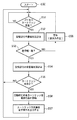
図11は、図3の現像カートリッジの誤装着検知シーケンスに加え、現像カートリッジの寿命検知のシーケンスを示す図である。図11は、図3と同様、電源ON時などの画像形成装置のイニシャル時などにおける現像カートリッジの寿命交換シーケンスを示すフローチャートである。寿命交換シーケンスは、制御部100内のROMなどの記憶されている制御プログラムに基づいて、電源オン時やドア開閉時などの所定のタイミングで実行される。
【0063】
まず、S50において検知シーケンスを開始し、次に、S51においてカートリッジが画像形成部位に装着されたか否かを判断する。装着されたことを検知すると、次にS52においてカートリッジの記憶部に書き込まれているトナー色情報を読み出す。制御部100は読み出したトナー色情報によってカートリッジが正しく装着されたか否か(図5のフローチャートと同様)を判断する。カートリッジが正しく装着されていないと判断された場合には、S58において誤装着である旨をしめす警告を出力する。また、カートリッジが正しく装着された場合には、次にS54において、記憶部からカートリッジの寿命に関する情報を読み出す。そしてS55において、読み出した寿命情報に基づいてカートリッジが寿命か否かを判断する。カートリッジが寿命であると判断された場合には、S56において、制御部100からの指示信号がモータM1に送信され、指示信号に基づきモータM1によってロータリ24を駆動されて、寿命となったカートリッジを自動的に着脱位置に移動する。移動後、S57においてカートリッジ交換の警告をホスト103または表示装置101に出力する。
【0064】
また、本実施形態に於いて、トナー無しなどでカートリッジが寿命となったことを検出した際にこの情報を記憶部に記憶させるようにすることで、ユーザが寿命となったプロセスカートリッジを再び誤って装着した際にも、記憶部からその情報を読み出し、即座にカートリッジの交換を促す警告を出すようにすることも可能である。
【0065】
なお、カートリッジの寿命を判断する場合、図示してはいないが、光学的な検知センサなどのトナーの残量を検出する手段を設けてトナー残量を検出し、検出したトナー残量と所定値(閾値)に到達した場合に、制御部100はトナー無しであると判断して、記憶部にトナー無しであることを示す情報を書き込む制御を行い、それに基づいて、制御部100はカートリッジの交換を促すメッセージ(信号)をホスト103や表示装置101に出力する。
【0066】
また、トナーの残量を検出する手段とは別に、現像ローラの総回転時間を記憶部に更新記録させて所定値(閾値)に到達した場合に、制御部100はカートリッジの寿命であると判断して、カートリッジの交換を促すメッセージ(信号)をホスト103や表示装置101に出力する。
【0067】
なお、上記のトナー無しを判断するための所定値(閾値)や現像ローラの総回転時間に対する所定値(閾値)はカートリッジの記憶部に記憶されても良いし、制御部100内のROMなどに記憶させておいても良い。
【0068】
なお、検出したトナー残量と所定値との比較による寿命判断や、現像ローラ総回転時間と所定値との比較による寿命判断は、画像形成動作中、または、画像形成動作後に適当なタイミングで実行される。
【0069】
一方、本実施形態では、ロータリに各色の現像カートリッジを装着された例を示したが、更に感光体と帯電手段及びクリーニング手段とを一体化した形態の各色プロセスカートリッジを装着させる構成としても同様な効果が得られることは言うまでもない。
【0070】
以上説明したとおり、本実施形態によれば、現像時に発生する飛散トナーによる汚れや現像電圧の電気ノイズの影響を受けることがなくなり、常に正確な通信を行うことができる。また、カートリッジが寿命となった場合には、即座にユーザが寿命となったカートリッジを交換することができる。
【0071】
(第2実施形態)
本発明の第2実施形態としてのカラープリンタについて図4を用いて説明する。本実施の形態に係るカラープリンタの全体的構成、機能については、図9に示すロータリ方式のカラープリンタとほぼ同様であるため、同様の部分については同一符号を付し詳しい説明は省略する。
【0072】
本実施の形態では、NVRAMへの読み出し/書き込みをプロセスカートリッジの着脱位置で行うのではなく、着脱位置以外の位置で行う点で上記第1実施形態と異なるものである。
【0073】
図4には着脱位置について詳細に示されており、P2の位置がカートリッジ着脱位置である。つまり、P2の位置に停止したカートリッジは、装置上面の蓋200を開け図中矢印方向へ操作することにより装置外へ取り出される。
【0074】
本実施形態では、カートリッジを着脱する位置に記憶部とアクセスするのではなく、読み出し/書き込み部242の位置は、着脱位置から、支持体の回転軸を中心にθ=90×n(°)(n=1,2,3)回転させた位置であってもよい。つまり、複数のカートリッジのうち1つが着脱位置にある場合の他のカートリッジの位置において記憶部とアクセスするような構成であっても良い。ここではカートリッジが4つであるからθ=90×n(°)(n=1,2,3)としているが、カートリッジが3つであれば、θ=120×n(°)(n=1,2)であるし、カートリッジが5つの場合には、θ=72×n(°)(n=1,2,3または4)となる。すなわち一般化すると、N個のカートリッジの場合に、その取り付け位置からθ=360°×n/N (n=1,2,...,orN)の位置で、記憶部とアクセスすることになる。
【0075】
これにより、この構成では、カートリッジを交換する着脱位置では記憶部とアクセスできないが、着脱位置で通信する場合に発生する、通信中にカートリッジが取り出されることによる通信エラーを防止することができる。
また、第1実施形態と同様、現像位置から離れた位置でメモリアクセスを行うことになるので飛散トナーやノイズの影響を受けることはなく常に正確な通信が可能である。
【0076】
ここで、本実施形態ではロータリを回転駆動するための駆動部であるモータやロータリを移動させるための構成については説明していないが、第1実施形態に記載されている構成と同様の構成及び制御を行うものである。
【0077】
なお、本実施形態においても、第1実施形態と同様に、カートリッジの誤装着防止、カートリッジの寿命検知の制御は制御部100で行われる。
【0078】
また、カートリッジの記憶部とのアクセスは非接触方式であっても、接触方式であっても良い。
【0079】
(第3実施形態)
本発明に係る画像形成装置の第3実施形態としてのロータリ方式のカラープリンタを図5に示す。本実施の形態に係るカラープリンタの全体的構成、機能については、図9に示すロータリ方式のカラープリンタとほぼ同様であるため、同様の部分については同一符号を付し詳しい説明は省略する。
【0080】
本実施形態では、第1、2実施形態とは異なり、カートリッジの着脱位置とは異なる位置で、かつ、アクセス位置を現像位置以外の位置で、現像カートリッジの記憶部であるメモリにアクセスすることを特徴としている。
【0081】
本プリンタは、それぞれに記憶部としてのフラッシュメモリを有した、4種類の現像剤を収容する4個のプロセスカートリッジ40a,b,c,dと、これらのプロセスカートリッジを回転可能に保持するカートリッジ保持手段としての回転支持体110と、を有している。そして、回転支持体(回転保持体)110によって、複数の現像カートリッジの1つが画像形成位置に配置された状態で、現像カートリッジに収容された現像剤によって像担持体上の潜像を可視化する。その画像形成位置以外の位置でプロセスカートリッジに設けられたフラッシュメモリにアクセスする。各々のフラッシュメモリには、第1実施形態と同様に記憶部に記憶される情報としては、例えばY現像カートリッジ24aの場合は、記憶部にはY現像カートリッジ内のトナーの色情報のほかに、Y現像カートリッジの製造時に付与されるシリアルナンバー、Y現像カートリッジを用いて画像形成を行ったページカウント数、Y現像カートリッジ内のトナーの残量、Y現像カートリッジの現像ローラ33aの総回転時間、また、それらから計算されるカートリッジ寿命情報、カートリッジが寿命であることを示す情報などカートリッジに関する情報が記憶されている。M現像カートリッジ,C現像カートリッジ,BK現像カートリッジの記憶部にもY現像カートリッジの記憶部と同様の情報が記憶されている。
【0082】
本実施の形態においては、図5のように、カートリッジ40a,b,c,dが感光ドラム10に対向する、画像形成位置(図中点線)から、時計回りでA1=135°回転させた位置P1において、フラッシュメモリ41a,b,c,dへの読み出し/書き込みを行うように読み出し/書き込み部142を設けた。
【0083】
現像位置から時計回りに90,180,270°回転させた位置がカートリッジの停止位置として定義されている。従って、その停止位置とは重ならないような位置として135°と設定している。この角度は装置の各部位の配置構成などによってロータリが停止可能であって記憶部と確実に通信可能な角度に配置しており、この角度に限定されるものではない。
【0084】
また、第1実施形態に記載されているように着脱位置とは別の位置で通信することにより外部からのホコリなどに影響されることなく(接触式通信の場合)確実に通信することが可能となる。
【0085】
なお、図5のP2の位置はカートリッジの着脱位置である。
【0086】
本実施形態では、制御部100からの指示信号がモータM1に送信され、モータM1によってロータリ110を▲1▼画像形成位置、▲2▼フラッシュメモリである記憶部とのアクセス位置、▲3▼着脱位置の3つの状態に回転移動することを可能としている。
【0087】
本実施形態によれば、現像時に発生する飛散トナーによる汚れや現像電圧の電気ノイズの影響を受けることがなくなり、常に正確な通信を行うことができる
ここで、本実施形態ではロータリを回転駆動するための駆動部であるモータやロータリを移動させるための構成については説明していないが、第1実施形態に記載されている構成と同様の構成及び制御を行うものである。
【0088】
なお、本実施形態においても、第1実施形態と同様に、カートリッジの誤装着防止、カートリッジの寿命検知の制御は制御部100で行われる。
【0089】
また、カートリッジの記憶部とのアクセスは非接触方式であっても、接触方式であっても良い。
【0090】
(第4実施形態)
本発明の第4実施形態としてのカラープリンタについて図6を用いて説明する。本実施の形態に係るカラープリンタの全体的構成、機能については、図9に示すロータリ方式のカラープリンタとほぼ同様であるため、同様の部分については同一符号を付し詳しい説明は省略する。
【0091】
本実施の形態では、NVRAMへの読み出し/書き込みを現像カートリッジの現像位置からその回転軸を中心にθ=90×n(°)(n=1,2,3)回転させた位置で行う点で上記第1,2実施形態と異なるものである。
【0092】
そこで、本実施の形態では、カートリッジが感光ドラムに対向した現像位置から180°回転させた位置P3において不揮発性記憶部への読み出し/書き込みを行うように本体の読み出し/書き込み部342を設けた。
【0093】
これにより、上記第1、第2実施形態の効果に加えて、着脱時に読み出し/書き込み部を介して制御部が記憶部へアクセスするための負担がかからないという効果がある。
【0094】
ここで、本実施の形態では現像位置から180°回転させた位置でメモリアクセスを行ったが、画像形成位置(現像位置)からの回転角度θは、これに限定されるものではない。カートリッジが4つの場合には、θは、90°、180°、270°の何れかであればよい。すなわち、カートリッジN個の場合には、
θ=360°×n/N(n=1,2,...,または(N−1))となる。
なお図5のP2の位置はカートリッジの着脱位置である。
【0095】
図でも示されているとおり、この着脱位置は画像形成位置とは異なる位置である。ここで、本実施形態ではロータリを回転駆動するための駆動部であるモータやロータリを移動させるための構成については説明していないが、第1実施形態に記載されている構成と同様の構成及び制御を行うものである。
【0096】
また、カートリッジの不揮発性記憶部に記憶される情報としては、例えばY現像カートリッジ24aの場合は、記憶部にはY現像カートリッジ内のトナーの色情報のほかに、Y現像カートリッジの製造時に付与されるシリアルナンバー、Y現像カートリッジを用いて画像形成を行ったページカウント数、Y現像カートリッジ内のトナーの残量、Y現像カートリッジの現像ローラ33aの総回転時間、また、それらから計算されるカートリッジ寿命情報、カートリッジが寿命であることを示す情報などカートリッジに関する情報が記憶されている。M現像カートリッジ,C現像カートリッジ,K現像カートリッジの記憶部にもY現像カートリッジの記憶部と同様の情報が記憶されている。
【0097】
なお、本実施形態においても、第1実施形態と同様に、カートリッジの誤装着防止、カートリッジの寿命検知の制御は制御部100で行われる。
【0098】
また、カートリッジの記憶部とのアクセスは非接触方式であっても、接触方式であっても良い。
【0099】
(第5実施形態)
本発明の第5実施形態としてのカラープリンタについて図7を用いて説明する。本実施形態に係るカラープリンタの全体的構成、機能については、図9に示すロータリ方式のカラープリンタとほぼ同様であるため、同様の部分については同一符号を付し詳しい説明は省略する。
【0100】
本実施の形態において、プロセスカートリッジは、現像剤収容部以外に、少なくとも感光体を一体的にカートリッジ化した像形成カートリッジである。
【0101】
本実施形態のカラープリンタにおいては、感光ドラム、一次帯電器、現像装置、クリーニング装置、トナーが一体的にカートリッジ化された像形成カートリッジa,b,c,dが回転支持体111の周りに配置されている。まずイエロートナーの入った像形成カートリッジaが中間転写ベルト105に対向する位置に回転してくる。ここで、像形成カートリッジa内の感光ドラム1aは、不図示の駆動手段によって図示矢印方向に駆動され、一次帯電器2aにより一様に帯電される。次いで、露光装置103よりイエローの画像模様に従ったレーザ光Lが、感光ドラム1aに照射され、感光ドラム1a上に潜像が形成される。更に感光ドラム1aが矢印方向に進むと現像装置4aによって感光ドラム上にトナー画像が形成される。中間転写ベルト105は感光ドラム1aと略同速で矢印方向に回転しており、感光ドラム1a上に形成担持されたトナー画像を一次転写ローラ108aに印加される1次転写バイアスによって、中間転写ベルト105の外周面に一次転写する。一方、感光ドラム1a上の転写残トナーは公知のブレード手段のクリーニング装置7aによって清掃される。以上の行程をイエロー色、マゼンタ色、シアン色、黒色について行うことによって中間転写ベルト105上には複数色のトナー像が形成される。次に、所定のタイミングで転写材カセット112内からピックアップローラー113によって転写材が給紙される。同時に二次転写ローラ108bに二次転写バイアスが印加され中間転写ベルト105から転写材へトナー画像が転写される。
【0102】
更に転写材は、搬送ベルト114によって定着装置106まで搬送され溶融固着されることによりカラー画像が得られる。また、中間転写ベルト105上の転写残トナーは中間転写クリーニングローラ115により電荷が付与され、次回の一次転写時に感光ドラム上に逆転写される。
【0103】
ここで、プロセスカートリッジa,b,c,dには、カートリッジに関する情報が記憶されるNVRAM41(記憶部)a,b,c,dがカートリッジ側面に設けられている。また、本実施の形態においては像形成カートリッジが中間転写ベルトに対向した位置から180°回転させた位置P4においてNVRAM41a,b,c,dへの読み出し/書き込みを行うように本体の読み出し/書き込み手段442を設けた。
【0104】
記憶部に記憶される情報としては、例えばYプロセスカートリッジ24aの場合は、記憶部にはY現像カートリッジ内のトナーの色情報のほかに、Yプロセスカートリッジの製造時に付与されるシリアルナンバー、Yプロセスカートリッジを用いて画像形成を行ったページカウント数、Yプロセスカートリッジ内のトナーの残量、Yプロセスカートリッジの現像ローラ33aの総回転時間、また、それらから計算されるカートリッジ寿命情報、カートリッジが寿命であることを示す情報などプロセスカートリッジに関する情報が記憶されている。Mプロセスカートリッジ,Cプロセスカートリッジ,Kプロセスカートリッジの記憶部にもプロセスカートリッジの記憶部と同様の情報が記憶されている。
【0105】
本実施形態によれば、感光ドラムと現像装置が一体的にカートリッジ化された像形成カートリッジを用いる場合にも、不揮発性記憶部と読み出し/書き込み手段杜の通信を常に正確に行うことができ、且つカートリッジ回転/停止制御の複雑化についても防止できる。
【0106】
また、本実施の形態では画像形成位置(現像位置)から180°回転させた位置でメモリアクセスを行ったが、上記の実施形態のように、現像位置以外の様々な位置でメモリアクセスを行なっても良い。例えば現像位置から90°或いは270°回転させた位置においても同様の効果を得ることができるし、カートリッジ着脱位置または、カートリッジ着脱位置から90°、180°或いは270°回転させた位置でメモリアクセスを行っても同様の効果を得ることができる。
【0107】
なお、図7のP2の位置はカートリッジの着脱位置である。図でも示されているとおり、この着脱位置は画像形成位置とは異なる位置である。
【0108】
ここで、本実施形態ではロータリを回転駆動するための駆動部であるモータやロータリを移動させるための構成については説明していないが、第1実施形態に記載されている構成と同様の構成及び制御を行うものである。
【0109】
また、カートリッジの誤装着検知の制御、カートリッジの寿命検知の制御については、第1実施形態と同様の制御を行うものである。
【0110】
なお、本実施形態においても、第1実施形態と同様に、カートリッジの誤装着防止、カートリッジの寿命検知の制御は制御部100で行われる。
【0111】
また、カートリッジの記憶部とのアクセスは非接触方式であっても、接触方式であっても良い。
【0112】
(他の実施形態)
上記第1〜第5実施形態では、取り扱い易さやコストの点から不揮発性記憶部としてNVRAMを使用したが、信号情報を書き換え可能に記憶、保持するものならばこれに限定されるものではない。例えば一般的なRAMや、書き換え可能なROM等の電気的な記憶部であっても、磁気記憶媒体や磁気バブルメモリ、光磁気メモリ等の磁気的記憶部であってもよい。
【0113】
また、上記実施の形態においては不揮発性記憶部と読み出し/書き込み手段を接触させて通信を行っているが、非接触による通信方式を採用しても同様の効果を得ることができる。
【0114】
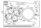
なお、上記第1〜第5実施形態ではカラープリンタは中間転写体を用いた中間転写方式のカラープリンタとして説明したが、図8に示すような感光ドラム201上のトナー画像を、転写材担持体205上に担持された転写材に順次転写することにより画像を形成する多重転写方式のカラープリンタを用いても同様の効果を得ることができる。ここで、図8における、204a,b,c,dは現像カートリッジ、241a,b,c,dは不揮発性記憶部、542は読み出し/書き込み手段、206は定着装置である。
【0115】
なお、本発明は、複数の機器から構成されるシステム(例えば複合機)に適用しても、一つの機器からなる装置(例えば、複写機、ファクシミリ装置など)に適用してもよい。また、本発明は、上述した実施形態に限定されるものではなく、同一の技術思想の変形例を含みうるものである。
【0116】
【発明の効果】
以上説明したように、本発明によれば、現像剤収容カートリッジに設けられた記憶部に対するアクセスを正確に行うことのできる画像形成装置及びその制御方法を提供することができる。
【図面の簡単な説明】
【図1】本発明の第1実施形態に係る画像形成装置を説明する構成図である。
【図2】現像手段であるY、M、C、Bk各色のトナーをそれぞれ内包する現像カートリッジ24a、24b、24c、24dを示す構成図である。
【図3】本発明の第1実施形態における、画像形成装置の制御フローを説明するフローチャートである。
【図4】本発明の第2実施形態に係る画像形成装置を説明する構成図である。
【図5】本発明の第3実施形態に係る画像形成装置を説明する構成図である。
【図6】本発明の第4実施形態に係る画像形成装置を説明する構成図である。
【図7】本発明の第5実施形態に係る画像形成装置を説明する構成図である。
【図8】本発明の他の実施形態に係る画像形成装置を説明する構成図である。
【図9】従来技術の構成図である。
【図10】カートリッジの記憶部の構成図である。
【図11】本発明の第1実施形態における、画像形成装置の制御フローを説明するフローチャートである。
【図12】カートリッジの移動の構成を説明する図である。[0001]
BACKGROUND OF THE INVENTION
The present invention relates to an image forming apparatus using an electrophotographic recording system such as a copying machine or a laser printer, and is particularly configured to be detachable in a main body of a color image forming apparatus, and at least one configuration of an image forming unit The present invention relates to an image forming apparatus having a plurality of cartridges including elements and a method for controlling the image forming apparatus.
[Prior art]
As a conventional color image forming apparatus, an image forming apparatus in which a plurality of developer containing cartridges can be attached and detached is known. FIG. 9 shows a rotary type image forming apparatus that holds a plurality of conventionally known developer containing cartridges in a detachable and rotatable manner. In this system, the cartridge holding unit performs image formation by placing any one developer containing cartridge at the image forming position.
[0002]
In the rotary type color printer of FIG. 9, the
[0003]
Further, the transfer material is conveyed to the
[0004]
Here, the
[0005]
[Problems to be solved by the invention]
However, when the NVRAM is accessed at such an image forming position (development position), it is likely to be affected by toner scattering and the development voltage, and there is a possibility that accurate data communication cannot be performed.
[0006]
That is, in a rotary type image forming apparatus, when a storage unit such as a non-volatile memory is provided in a developer containing cartridge and the life of the cartridge is to be managed, the storage unit is stored at the image forming position (development position). When trying to access, there is a possibility that communication cannot be performed accurately due to the influence of scattered developer or electric noise of the development voltage.
[0007]
SUMMARY OF THE INVENTION An object of the present invention is to improve an image forming apparatus having a plurality of cartridges that are detachable and that include at least one component of an image forming unit.
[0008]
Another object of the present invention is to provide an image forming apparatus capable of accurately accessing a storage unit provided in a cartridge including at least one component of the image forming unit, and a control method thereof. .
[0009]
Still another object of the present invention is to provide an image forming apparatus in which a cartridge having at least one component of a plurality of image forming units can be mounted, and an image forming apparatus that allows a developer containing cartridge that has reached the end of its life to be replaced immediately. And providing a control method of the image forming apparatus.
[0010]
[Means for Solving the Problems]
The image forming apparatus according to the present invention includes a storage unit.DoA developer containing cartridge;
The developer containing cartridgeMultiple images can be held for image formationrotationMovePossibleNaCartridge holding means;
Access means for accessing the storage means;TheHave
The cartridge holding means rotates and moves to a detachable attachment / detachment position when the developer storage cartridge is attached / detached,
The access means is, A plurality of cartridges held by the cartridge holding meansDeveloper containing cartridgeAmong the storage means of the developer containing cartridge at the attachment / detachment position.It is characterized by access.
[0014]
DETAILED DESCRIPTION OF THE INVENTION
The image forming apparatus according to the present invention will be described below in more detail with reference to the drawings.
[0015]
<First Embodiment>
1st Embodiment concerning this invention is described with reference to FIG.1, FIG.2, FIG.3. FIG. 1 is a configuration diagram illustrating an image forming apparatus according to the present embodiment. The image forming apparatus is electrically connected to a
[0016]
In FIG. 1,
[0017]
First, the first electrostatic latent image is developed and visualized by the first developing
[0018]
The toner remaining on the surface of the
[0019]
The same process is repeated, and each time, a second color toner image developed with M toner, a third color toner image developed with C toner, and a fourth color toner image developed with Bk toner are sequentially provided. A color toner image is formed by transferring and laminating on the surface of the
[0020]
In addition, the toner remaining on the surface of the
[0021]
The rotary 24 that detachably holds the developing cartridge is configured to move in the directions of arrows D and E shown in FIG. 1, and the rotary 24 moves in the direction of arrow E when no image is formed. Stopped in the state of being. In this case, the developing cartridge is stopped at the attaching / detaching position, and the developing roller is configured not to contact the
[0022]
As shown in FIG. 12, the configuration for moving the rotary 24 in the directions of arrows D and E is configured to be movable in the directions of arrows D and E with an axis J provided at the top of the rotary as a fulcrum. The movement is provided with a coupling cam (CAM) that pushes the plate L provided on the rotary frame W, an instruction signal from the
[0023]
In the figure, 24a, 24b, 24c and 24d are developing cartridges, and 21 is a photosensitive drum.
[0024]
FIG. 2 is a configuration diagram showing developing
[0025]
In order to simplify the description, a case where the developing
[0026]
The developing
[0027]
In the present embodiment, the developing
[0028]
In the case where the developing
[0029]
Further, when a coating layer is provided on the outer periphery of the elastic layer in consideration of charging of the toner, a polyamide resin, a urethane resin, a silicone resin, an acrylic resin, a fluororesin, or a resin in which these are mixed is preferably used.
[0030]
As the developing
[0031]
The toner agitated by the agitating
[0032]
When the toner carried on the developing
[0033]
In the embodiment according to the present invention, the image forming apparatus is not limited to the above-described contact development method, and can be used regardless of the development method, and a known non-contact development method (jumping development or the like). May be used.
[0034]
Next, the storage units Re, Rf, Rg, and Rh provided in the developing
[0035]
The storage units Re to Rh are configured to read and write data by communicating with the reading /
[0036]
The storage units Re to Rh are provided on the container side surfaces of the respective cartridges. In each of the storage units Re to Rh, data such as toner color information contained in the developing means of each cartridge is stored in advance. At the cartridge attachment / detachment position in FIG. 1, the storage unit images the data in the memory via the read /
[0037]
In FIG. 1, when it is in the position of the
[0038]
As information stored in the storage unit, information as shown in FIG. 10 is stored.
[0039]
For example, in the case of the
[0040]
Here, a process at the start of use in which the developing
[0041]
In the main body of the image forming apparatus, developing
[0042]
When the developing
[0043]
Next, when it is detected that the developing cartridge replacement cover (not shown) of the image forming apparatus is opened by the user, the developing cartridge is mounted in the rotary, and the replacement cover is closed again, the
[0044]
Here, the present embodiment is characterized in that the
[0045]
Further, even if the user accidentally installs a cartridge of a different color, this can be detected immediately.
[0046]
In other words, since it is configured to read at the attachment / detachment position, the time for rotating the rotary to access the memory, which occurs when the memory is accessed at a part different from the attachment / detachment position, or in the case of incorrect attachment It is also possible to eliminate a large amount of time until the user is notified of erroneous attachment, such as time for returning to the attachment / detachment position.
[0047]
The developing
[0048]
Next, control for preventing erroneous mounting of the developing cartridge during normal use will be described.
[0049]
When the color information written in the storage units Re to Rh is detected at a predetermined timing at which the developing
[0050]
In addition, when the color information read from the storage unit of the mounted developing cartridge does not match the color of the rotary image forming unit, the
[0051]
FIG. 3 is a flowchart specifically illustrating determination of the mounting position of the developing cartridge at a predetermined timing such as when the image forming apparatus is initialized when the power is turned on. The determination procedure will be described in more detail with reference to FIG.
[0052]
First, when it is detected that the developing cartridge is attached to the Y image forming portion in the rotary of the color printer main body in the standby state (S11-YES), the process proceeds to step S12, and the
[0053]
If the developing cartridge is not correctly mounted (S13-NO), the process proceeds to step S28, and a warning of incorrect mounting is displayed.
[0054]
When it is detected in step S15 that the next developing cartridge is mounted (S15-YES), the
[0055]
If it is determined in step S17 that the developing cartridge is not correctly mounted (S17-NO), the process proceeds to step S29, and a warning indicating that it is erroneously mounted is displayed.
[0056]
When it is detected in step S19 that the next developing cartridge has been installed (S19-YES), the
If it is determined in step S21 that the developing cartridge is not correctly mounted (S21-NO), the process proceeds to step S30, and a warning indicating that the developing cartridge is erroneously mounted is displayed.
[0057]
When it is detected in step S23 that the last developing cartridge is mounted (S23-YES), the
If it is determined in steps S25 and S26 that the developing cartridge is not correctly mounted on the predetermined image forming unit, the process proceeds to steps S31 and S32, respectively, and a warning of incorrect mounting is displayed.
[0058]
When the color information read from the storage unit of the mounted developing cartridge does not match the color of the rotary image forming unit, the
[0059]
If the Y, M, C, and Bk developing cartridges are remounted according to this warning, they are processed again in accordance with the procedures from the above steps S11, S15, S19, and S23.
[0060]
In addition, when any mounted developing cartridge is replaced at the end of its life, the determination of mounting the developing cartridge is processed in the same manner, except that only the developing cartridge of the replaced color is processed. The
[0061]
Further, in this image forming apparatus, when the
Here, for example, in a state where the life of the M developing cartridge is detected and rotated to the attachment / detachment position, when the user replaces the cartridge that has reached the end of the life with a new cartridge, the flow of steps S15 to S18 in FIG. After the process is executed, the process is skipped to S26. That is, when only one cartridge is exchanged, control is performed so as to skip the processing of the other colors. By controlling in this way, the user can easily replace a cartridge that has reached the end of its life and without changing the color, so that it is possible to improve usability such as reducing troublesomeness.
[0062]
FIG. 11 is a diagram showing a developing cartridge life detection sequence in addition to the erroneous mounting detection sequence of the developing cartridge of FIG. FIG. 11 is a flowchart showing a life replacement sequence of the developing cartridge at the time of initializing the image forming apparatus such as when the power is turned on, as in FIG. The life replacement sequence is executed at a predetermined timing such as when the power is turned on or when the door is opened / closed based on a control program stored in the
[0063]
First, in S50, the detection sequence is started, and then in S51, it is determined whether or not the cartridge is mounted on the image forming portion. When it is detected that the toner cartridge is mounted, the toner color information written in the storage unit of the cartridge is read in S52. The
[0064]
Further, in this embodiment, when it is detected that the cartridge has reached the end of its life due to no toner or the like, this information is stored in the storage unit, so that the process cartridge that has reached the end of the life of the user can be mistaken again. It is also possible to read out the information from the storage unit and issue a warning prompting the replacement of the cartridge immediately even when it is mounted.
[0065]
When determining the life of the cartridge, although not shown, a means for detecting the remaining amount of toner such as an optical detection sensor is provided to detect the remaining amount of toner, and the detected remaining amount of toner and a predetermined value are detected. When the (threshold) is reached, the
[0066]
In addition to the means for detecting the remaining amount of toner, when the total rotation time of the developing roller is updated and recorded in the storage unit and reaches a predetermined value (threshold value), the
[0067]
The predetermined value (threshold value) for determining the absence of toner and the predetermined value (threshold value) with respect to the total rotation time of the developing roller may be stored in a storage unit of the cartridge, or may be stored in a ROM in the
[0068]
The life judgment by comparing the detected remaining toner amount with a predetermined value and the life judgment by comparing the total developing roller rotation time with a predetermined value are executed at an appropriate timing during the image forming operation or after the image forming operation. Is done.
[0069]
On the other hand, in the present embodiment, an example in which the developing cartridges for each color are mounted on the rotary is shown. However, the same configuration can be applied to mounting each color process cartridge in which the photosensitive member, the charging unit, and the cleaning unit are integrated. Needless to say, an effect can be obtained.
[0070]
As described above, according to the present embodiment, it is possible to always perform accurate communication without being affected by the contamination due to scattered toner generated during development and the electric noise of the development voltage. Further, when the cartridge has reached the end of its life, the user can immediately replace the cartridge at the end of its life.
[0071]
(Second Embodiment)
A color printer as a second embodiment of the present invention will be described with reference to FIG. The overall configuration and function of the color printer according to the present embodiment is almost the same as that of the rotary type color printer shown in FIG. 9, and thus the same parts are denoted by the same reference numerals and detailed description thereof is omitted.
[0072]
The present embodiment is different from the first embodiment in that reading / writing to the NVRAM is not performed at the attachment / detachment position of the process cartridge but at a position other than the attachment / detachment position.
[0073]
FIG. 4 shows the attachment / detachment position in detail, and the position P2 is the cartridge attachment / detachment position. That is, the cartridge stopped at the position P2 is taken out of the apparatus by opening the
[0074]
In this embodiment, instead of accessing the storage unit at the position where the cartridge is attached / detached, the position of the read /
[0075]
Accordingly, in this configuration, the storage unit cannot be accessed at the attachment / detachment position where the cartridge is replaced, but a communication error caused when the cartridge is taken out during communication, which occurs when communicating at the attachment / detachment position, can be prevented.
Further, as in the first embodiment, memory access is performed at a position away from the development position, so that accurate communication is always possible without being affected by scattered toner or noise.
[0076]
Here, in the present embodiment, a motor that is a driving unit for rotationally driving the rotary and a configuration for moving the rotary are not described, but a configuration similar to the configuration described in the first embodiment and Control is performed.
[0077]
In the present embodiment as well, as in the first embodiment, control of cartridge mis-installation prevention and cartridge life detection is performed by the
[0078]
Further, the access to the storage unit of the cartridge may be a non-contact method or a contact method.
[0079]
(Third embodiment)
FIG. 5 shows a rotary type color printer as a third embodiment of the image forming apparatus according to the present invention. The overall configuration and function of the color printer according to the present embodiment is almost the same as that of the rotary type color printer shown in FIG. 9, and thus the same parts are denoted by the same reference numerals and detailed description thereof is omitted.
[0080]
In the present embodiment, unlike the first and second embodiments, the memory serving as the storage unit of the developing cartridge is accessed at a position different from the mounting position of the cartridge and at an access position other than the developing position. It is a feature.
[0081]
The printer has four
[0082]
In the present embodiment, as shown in FIG. 5, the
[0083]
The position rotated 90, 180, 270 degrees clockwise from the development position is defined as the stop position of the cartridge. Accordingly, the position is set to 135 ° so as not to overlap the stop position. This angle is arranged at an angle at which the rotary can be stopped depending on the arrangement configuration of each part of the apparatus and can be reliably communicated with the storage unit, and is not limited to this angle.
[0084]
In addition, as described in the first embodiment, by communicating at a position different from the attachment / detachment position, it is possible to reliably communicate without being affected by external dust (in the case of contact communication). It becomes.
[0085]
Note that the position P2 in FIG. 5 is the mounting / demounting position of the cartridge.
[0086]
In this embodiment, an instruction signal from the
[0087]
According to the present embodiment, it is possible to always perform accurate communication without being affected by contamination due to scattered toner generated during development and electrical noise of the development voltage.
Here, in the present embodiment, a motor that is a driving unit for rotationally driving the rotary and a configuration for moving the rotary are not described, but a configuration similar to the configuration described in the first embodiment and Control is performed.
[0088]
In the present embodiment as well, as in the first embodiment, control of cartridge mis-installation prevention and cartridge life detection is performed by the
[0089]
Further, the access to the storage unit of the cartridge may be a non-contact method or a contact method.
[0090]
(Fourth embodiment)
A color printer as a fourth embodiment of the present invention will be described with reference to FIG. The overall configuration and function of the color printer according to the present embodiment is almost the same as that of the rotary type color printer shown in FIG. 9, and thus the same parts are denoted by the same reference numerals and detailed description thereof is omitted.
[0091]
In this embodiment, reading / writing to the NVRAM is performed at a position rotated from the developing position of the developing cartridge by θ = 90 × n (°) (n = 1, 2, 3) around its rotation axis. This is different from the first and second embodiments.
[0092]
Therefore, in the present embodiment, the reading /
[0093]
Thereby, in addition to the effects of the first and second embodiments, there is an effect that a load for the control unit to access the storage unit via the read / write unit is not applied during attachment / detachment.
[0094]
In this embodiment, the memory access is performed at a position rotated 180 ° from the development position. However, the rotation angle θ from the image forming position (development position) is not limited to this. When there are four cartridges, θ may be any of 90 °, 180 °, and 270 °. That is, in the case of N cartridges,
θ = 360 ° × n / N (n = 1, 2,..., or (N−1)).
Note that the position P2 in FIG. 5 is the mounting / demounting position of the cartridge.
[0095]
As shown in the figure, this attachment / detachment position is a position different from the image forming position. Here, in the present embodiment, a motor that is a driving unit for rotationally driving the rotary and a configuration for moving the rotary are not described, but a configuration similar to the configuration described in the first embodiment and Control is performed.
[0096]
As information stored in the non-volatile storage unit of the cartridge, for example, in the case of the
[0097]
In the present embodiment as well, as in the first embodiment, control of cartridge mis-installation prevention and cartridge life detection is performed by the
[0098]
Further, the access to the storage unit of the cartridge may be a non-contact method or a contact method.
[0099]
(Fifth embodiment)
A color printer as a fifth embodiment of the present invention will be described with reference to FIG. The overall configuration and functions of the color printer according to this embodiment are substantially the same as those of the rotary type color printer shown in FIG.
[0100]
In the present embodiment, the process cartridge is an image forming cartridge in which at least the photosensitive member is integrated into a cartridge in addition to the developer accommodating portion.
[0101]
In the color printer of this embodiment, the photosensitive drum, the primary charger, the developing device, the cleaning device, and the image forming cartridges a, b, c, and d in which toner is integrally formed are arranged around the
[0102]
Further, the transfer material is conveyed to the
[0103]
Here, the process cartridges a, b, c, and d are provided with NVRAM 41 (storage units) a, b, c, and d on the side surfaces of the cartridge in which information related to the cartridges is stored. Further, in the present embodiment, the reading / writing means of the main body so that the reading / writing to the
[0104]
As information stored in the storage unit, for example, in the case of the
[0105]
According to the present embodiment, even when an image forming cartridge in which the photosensitive drum and the developing device are integrally formed into a cartridge is used, communication between the nonvolatile storage unit and the reading / writing unit can always be accurately performed. In addition, complication of cartridge rotation / stop control can be prevented.
[0106]
In this embodiment, memory access is performed at a position rotated by 180 ° from the image forming position (development position). However, as in the above embodiment, memory access is performed at various positions other than the development position. Also good. For example, the same effect can be obtained at a position rotated by 90 ° or 270 ° from the developing position, and memory access can be performed at the cartridge attaching / detaching position or the position rotated by 90 °, 180 ° or 270 ° from the cartridge attaching / detaching position. The same effect can be obtained even if it goes.
[0107]
Note that the position P2 in FIG. 7 is the cartridge attachment / detachment position. As shown in the figure, this attachment / detachment position is a position different from the image forming position.
[0108]
Here, in the present embodiment, a motor that is a driving unit for rotationally driving the rotary and a configuration for moving the rotary are not described, but a configuration similar to the configuration described in the first embodiment and Control is performed.
[0109]
Further, the control for detecting the erroneous mounting of the cartridge and the control for detecting the life of the cartridge are the same as those in the first embodiment.
[0110]
In the present embodiment as well, as in the first embodiment, control of cartridge mis-installation prevention and cartridge life detection is performed by the
[0111]
Further, the access to the storage unit of the cartridge may be a non-contact method or a contact method.
[0112]
(Other embodiments)
In the first to fifth embodiments, NVRAM is used as a nonvolatile storage unit from the viewpoint of ease of handling and cost. However, the present invention is not limited to this as long as signal information is stored and retained in a rewritable manner. For example, it may be an electric storage unit such as a general RAM or a rewritable ROM, or a magnetic storage unit such as a magnetic storage medium, a magnetic bubble memory, or a magneto-optical memory.
[0113]
Further, in the above embodiment, the non-volatile storage unit and the reading / writing means are brought into contact for communication, but the same effect can be obtained even if a non-contact communication method is adopted.
[0114]
In the first to fifth embodiments, the color printer is described as an intermediate transfer type color printer using an intermediate transfer body. However, a toner image on the
[0115]
Note that the present invention may be applied to a system (for example, a multi-function peripheral) configured by a plurality of devices or an apparatus (for example, a copier, a facsimile machine, etc.) including a single device. Further, the present invention is not limited to the above-described embodiments, and can include modifications of the same technical idea.
[0116]
【The invention's effect】
As described above, according to the present invention, it is possible to provide an image forming apparatus that can accurately access a storage unit provided in a developer containing cartridge, and a control method therefor.
[Brief description of the drawings]
FIG. 1 is a configuration diagram illustrating an image forming apparatus according to a first embodiment of the present invention.
FIG. 2 is a configuration diagram illustrating developing
FIG. 3 is a flowchart illustrating a control flow of the image forming apparatus according to the first embodiment of the present invention.
FIG. 4 is a configuration diagram illustrating an image forming apparatus according to a second embodiment of the present invention.
FIG. 5 is a configuration diagram illustrating an image forming apparatus according to a third embodiment of the present invention.
FIG. 6 is a configuration diagram illustrating an image forming apparatus according to a fourth embodiment of the present invention.
FIG. 7 is a configuration diagram illustrating an image forming apparatus according to a fifth embodiment of the present invention.
FIG. 8 is a configuration diagram illustrating an image forming apparatus according to another embodiment of the present invention.
FIG. 9 is a configuration diagram of the prior art.
FIG. 10 is a configuration diagram of a storage unit of the cartridge.
FIG. 11 is a flowchart illustrating a control flow of the image forming apparatus according to the first embodiment of the present invention.
FIG. 12 is a diagram illustrating a configuration for moving a cartridge.
Claims (5)
前記現像剤収容カートリッジを複数保持可能で、画像形成するために回転移動可能なカートリッジ保持手段と、
前記記憶手段にアクセスするアクセス手段と、を有し、
前記カートリッジ保持手段は、前記現像剤収容カートリッジを着脱するときに、前記現像剤収容カートリッジを着脱可能な着脱位置に回転移動し、
前記アクセス手段は、前記カートリッジ保持手段に保持された複数の現像剤収容カートリッジのうち、前記着脱位置にある前記現像剤収容カートリッジの記憶手段にアクセスすることを特徴とする画像形成装置。A developer containing cartridge to have a storage means,
The developer containing cartridge can more holding, and rotating movable cartridge holding means to image forming,
Anda access means for accessing said memory means,
The cartridge holding means rotates and moves to a detachable attachment / detachment position when the developer storage cartridge is attached / detached,
The image forming apparatus according to claim 1 , wherein the access unit accesses a storage unit of the developer containing cartridge at the attachment / detachment position among the plurality of developer containing cartridges held by the cartridge holding unit .
前記アクセス手段は、前記着脱位置に装着された現像剤収容カートリッジの記憶手段から前記現像剤の色に関する情報を読み出し、読み出した情報に基づいて装着された前記現像剤収容カートリッジが、前記カートリッジ保持手段の複数の装着部のうち前記現像剤の色に対応する装着部に装着されたかを判断することを特徴とする請求項1乃至4のいずれか1項に記載の画像形成装置。 The access means reads information relating to the color of the developer from the storage means of the developer containing cartridge attached at the attachment / detachment position, and the developer containing cartridge attached based on the read information is the cartridge holding means. 5. The image forming apparatus according to claim 1, wherein the image forming apparatus is configured to determine whether the plurality of mounting portions are mounted on a mounting portion corresponding to the color of the developer.
Priority Applications (1)
| Application Number | Priority Date | Filing Date | Title |
|---|---|---|---|
| JP2003008575A JP4314036B2 (en) | 2002-01-16 | 2003-01-16 | Image forming apparatus and image forming apparatus control method |
Applications Claiming Priority (5)
| Application Number | Priority Date | Filing Date | Title |
|---|---|---|---|
| JP2002-7985 | 2002-01-16 | ||
| JP2002007985 | 2002-01-16 | ||
| JP2002054661 | 2002-02-28 | ||
| JP2002-54661 | 2002-02-28 | ||
| JP2003008575A JP4314036B2 (en) | 2002-01-16 | 2003-01-16 | Image forming apparatus and image forming apparatus control method |
Related Child Applications (1)
| Application Number | Title | Priority Date | Filing Date |
|---|---|---|---|
| JP2009102331A Division JP2009163267A (en) | 2002-01-16 | 2009-04-20 | Image forming device |
Publications (3)
| Publication Number | Publication Date |
|---|---|
| JP2003323088A JP2003323088A (en) | 2003-11-14 |
| JP2003323088A5 JP2003323088A5 (en) | 2006-02-02 |
| JP4314036B2 true JP4314036B2 (en) | 2009-08-12 |
Family
ID=29553956
Family Applications (1)
| Application Number | Title | Priority Date | Filing Date |
|---|---|---|---|
| JP2003008575A Expired - Fee Related JP4314036B2 (en) | 2002-01-16 | 2003-01-16 | Image forming apparatus and image forming apparatus control method |
Country Status (1)
| Country | Link |
|---|---|
| JP (1) | JP4314036B2 (en) |
Families Citing this family (4)
| Publication number | Priority date | Publication date | Assignee | Title |
|---|---|---|---|---|
| JP2005250374A (en) * | 2004-03-08 | 2005-09-15 | Fuji Xerox Co Ltd | Image forming apparatus |
| JP5606867B2 (en) * | 2010-10-22 | 2014-10-15 | 株式会社沖データ | Image forming apparatus |
| JP5765090B2 (en) * | 2011-06-28 | 2015-08-19 | ブラザー工業株式会社 | Image forming apparatus |
| JP2016018041A (en) * | 2014-07-07 | 2016-02-01 | 富士ゼロックス株式会社 | Image forming apparatus |
-
2003
- 2003-01-16 JP JP2003008575A patent/JP4314036B2/en not_active Expired - Fee Related
Also Published As
| Publication number | Publication date |
|---|---|
| JP2003323088A (en) | 2003-11-14 |
Similar Documents
| Publication | Publication Date | Title |
|---|---|---|
| JP4574740B2 (en) | Image forming apparatus | |
| US7031623B2 (en) | Image forming apparatus, management method for replacement part used therefor, and management program for replacement part | |
| US7286775B2 (en) | Image formation device enabling switching display of remaining developing agent in monochrome printing mode | |
| JP3995024B2 (en) | Image forming apparatus and computer system | |
| US8428477B2 (en) | Image forming apparatus | |
| JP2004013025A (en) | Image forming apparatus, method and system for replacing consumable members for the apparatus | |
| US7313334B2 (en) | Image formation device enabling switching between color printing mode and monochrome printing mode | |
| KR100634324B1 (en) | Image formation device, development unit, and computer system | |
| JP4314036B2 (en) | Image forming apparatus and image forming apparatus control method | |
| KR100648764B1 (en) | Image formation device, developing unit, and computer system | |
| JPH06250514A (en) | Developing device and image forming device | |
| JP3743352B2 (en) | Image forming apparatus, computer program, and computer system | |
| JP2008129532A (en) | Image forming apparatus | |
| JP4492603B2 (en) | Image forming apparatus | |
| JP3888139B2 (en) | Image forming apparatus, computer program, and computer system | |
| JP2004333890A (en) | Image forming apparatus | |
| JP4049205B2 (en) | Image forming apparatus | |
| JP2003156912A (en) | Image forming apparatus, computer program and computer system | |
| JP2003280324A (en) | Color image forming apparatus |
Legal Events
| Date | Code | Title | Description |
|---|---|---|---|
| A521 | Request for written amendment filed |
Free format text: JAPANESE INTERMEDIATE CODE: A523 Effective date: 20051209 |
|
| A621 | Written request for application examination |
Free format text: JAPANESE INTERMEDIATE CODE: A621 Effective date: 20051209 |
|
| A977 | Report on retrieval |
Free format text: JAPANESE INTERMEDIATE CODE: A971007 Effective date: 20090216 |
|
| A131 | Notification of reasons for refusal |
Free format text: JAPANESE INTERMEDIATE CODE: A131 Effective date: 20090220 |
|
| A521 | Request for written amendment filed |
Free format text: JAPANESE INTERMEDIATE CODE: A523 Effective date: 20090420 |
|
| TRDD | Decision of grant or rejection written | ||
| A01 | Written decision to grant a patent or to grant a registration (utility model) |
Free format text: JAPANESE INTERMEDIATE CODE: A01 Effective date: 20090511 |
|
| A01 | Written decision to grant a patent or to grant a registration (utility model) |
Free format text: JAPANESE INTERMEDIATE CODE: A01 |
|
| A61 | First payment of annual fees (during grant procedure) |
Free format text: JAPANESE INTERMEDIATE CODE: A61 Effective date: 20090518 |
|
| FPAY | Renewal fee payment (event date is renewal date of database) |
Free format text: PAYMENT UNTIL: 20120522 Year of fee payment: 3 |
|
| R150 | Certificate of patent or registration of utility model |
Free format text: JAPANESE INTERMEDIATE CODE: R150 |
|
| FPAY | Renewal fee payment (event date is renewal date of database) |
Free format text: PAYMENT UNTIL: 20120522 Year of fee payment: 3 |
|
| FPAY | Renewal fee payment (event date is renewal date of database) |
Free format text: PAYMENT UNTIL: 20130522 Year of fee payment: 4 |
|
| FPAY | Renewal fee payment (event date is renewal date of database) |
Free format text: PAYMENT UNTIL: 20140522 Year of fee payment: 5 |
|
| LAPS | Cancellation because of no payment of annual fees |