JP4312836B2 - Selective diversity combination - Google Patents
Selective diversity combination Download PDFInfo
- Publication number
- JP4312836B2 JP4312836B2 JP55028098A JP55028098A JP4312836B2 JP 4312836 B2 JP4312836 B2 JP 4312836B2 JP 55028098 A JP55028098 A JP 55028098A JP 55028098 A JP55028098 A JP 55028098A JP 4312836 B2 JP4312836 B2 JP 4312836B2
- Authority
- JP
- Japan
- Prior art keywords
- signal
- interference
- combination
- level
- combining
- Prior art date
- Legal status (The legal status is an assumption and is not a legal conclusion. Google has not performed a legal analysis and makes no representation as to the accuracy of the status listed.)
- Expired - Lifetime
Links
- 238000000034 method Methods 0.000 claims description 54
- 230000006735 deficit Effects 0.000 claims description 23
- 238000004891 communication Methods 0.000 claims description 14
- 230000015654 memory Effects 0.000 claims description 6
- 230000000903 blocking effect Effects 0.000 claims description 5
- 238000010586 diagram Methods 0.000 description 11
- 238000012545 processing Methods 0.000 description 6
- 230000001360 synchronised effect Effects 0.000 description 5
- 238000005562 fading Methods 0.000 description 4
- 239000011159 matrix material Substances 0.000 description 4
- 230000008901 benefit Effects 0.000 description 3
- 230000008569 process Effects 0.000 description 3
- 239000006185 dispersion Substances 0.000 description 2
- 230000006870 function Effects 0.000 description 2
- 238000010295 mobile communication Methods 0.000 description 2
- 230000004048 modification Effects 0.000 description 2
- 238000012986 modification Methods 0.000 description 2
- 238000012549 training Methods 0.000 description 2
- 238000004364 calculation method Methods 0.000 description 1
- 230000001413 cellular effect Effects 0.000 description 1
- 230000002596 correlated effect Effects 0.000 description 1
- 230000001419 dependent effect Effects 0.000 description 1
- 238000013461 design Methods 0.000 description 1
- 238000002592 echocardiography Methods 0.000 description 1
- 230000000694 effects Effects 0.000 description 1
- 230000001771 impaired effect Effects 0.000 description 1
- 230000003993 interaction Effects 0.000 description 1
- 230000010287 polarization Effects 0.000 description 1
- 230000035945 sensitivity Effects 0.000 description 1
- 230000000638 stimulation Effects 0.000 description 1
Images


Classifications
-
- H—ELECTRICITY
- H04—ELECTRIC COMMUNICATION TECHNIQUE
- H04B—TRANSMISSION
- H04B7/00—Radio transmission systems, i.e. using radiation field
- H04B7/02—Diversity systems; Multi-antenna system, i.e. transmission or reception using multiple antennas
- H04B7/04—Diversity systems; Multi-antenna system, i.e. transmission or reception using multiple antennas using two or more spaced independent antennas
- H04B7/08—Diversity systems; Multi-antenna system, i.e. transmission or reception using multiple antennas using two or more spaced independent antennas at the receiving station
- H04B7/0837—Diversity systems; Multi-antenna system, i.e. transmission or reception using multiple antennas using two or more spaced independent antennas at the receiving station using pre-detection combining
- H04B7/0842—Weighted combining
- H04B7/0848—Joint weighting
- H04B7/0857—Joint weighting using maximum ratio combining techniques, e.g. signal-to- interference ratio [SIR], received signal strenght indication [RSS]
-
- H—ELECTRICITY
- H04—ELECTRIC COMMUNICATION TECHNIQUE
- H04B—TRANSMISSION
- H04B7/00—Radio transmission systems, i.e. using radiation field
- H04B7/02—Diversity systems; Multi-antenna system, i.e. transmission or reception using multiple antennas
- H04B7/04—Diversity systems; Multi-antenna system, i.e. transmission or reception using multiple antennas using two or more spaced independent antennas
- H04B7/08—Diversity systems; Multi-antenna system, i.e. transmission or reception using multiple antennas using two or more spaced independent antennas at the receiving station
- H04B7/0837—Diversity systems; Multi-antenna system, i.e. transmission or reception using multiple antennas using two or more spaced independent antennas at the receiving station using pre-detection combining
- H04B7/0842—Weighted combining
- H04B7/0845—Weighted combining per branch equalization, e.g. by an FIR-filter or RAKE receiver per antenna branch
-
- H—ELECTRICITY
- H04—ELECTRIC COMMUNICATION TECHNIQUE
- H04B—TRANSMISSION
- H04B7/00—Radio transmission systems, i.e. using radiation field
- H04B7/02—Diversity systems; Multi-antenna system, i.e. transmission or reception using multiple antennas
- H04B7/04—Diversity systems; Multi-antenna system, i.e. transmission or reception using multiple antennas using two or more spaced independent antennas
- H04B7/08—Diversity systems; Multi-antenna system, i.e. transmission or reception using multiple antennas using two or more spaced independent antennas at the receiving station
- H04B7/0868—Hybrid systems, i.e. switching and combining
- H04B7/0871—Hybrid systems, i.e. switching and combining using different reception schemes, at least one of them being a diversity reception scheme
-
- H—ELECTRICITY
- H04—ELECTRIC COMMUNICATION TECHNIQUE
- H04L—TRANSMISSION OF DIGITAL INFORMATION, e.g. TELEGRAPHIC COMMUNICATION
- H04L1/00—Arrangements for detecting or preventing errors in the information received
- H04L1/02—Arrangements for detecting or preventing errors in the information received by diversity reception
- H04L1/06—Arrangements for detecting or preventing errors in the information received by diversity reception using space diversity
-
- H—ELECTRICITY
- H04—ELECTRIC COMMUNICATION TECHNIQUE
- H04B—TRANSMISSION
- H04B7/00—Radio transmission systems, i.e. using radiation field
- H04B7/02—Diversity systems; Multi-antenna system, i.e. transmission or reception using multiple antennas
- H04B7/04—Diversity systems; Multi-antenna system, i.e. transmission or reception using multiple antennas using two or more spaced independent antennas
- H04B7/08—Diversity systems; Multi-antenna system, i.e. transmission or reception using multiple antennas using two or more spaced independent antennas at the receiving station
- H04B7/0837—Diversity systems; Multi-antenna system, i.e. transmission or reception using multiple antennas using two or more spaced independent antennas at the receiving station using pre-detection combining
- H04B7/0842—Weighted combining
- H04B7/086—Weighted combining using weights depending on external parameters, e.g. direction of arrival [DOA], predetermined weights or beamforming
Landscapes
- Engineering & Computer Science (AREA)
- Computer Networks & Wireless Communication (AREA)
- Signal Processing (AREA)
- Radio Transmission System (AREA)
- Mobile Radio Communication Systems (AREA)
Description
発明の分野
本発明は、一般的に、多重アンテナを有する受信器におけるデジタル変調された無線信号の処理に関し、詳細には、信号の減損を低減するための無線信号のダイバーシチイ組合せに関する。
発明の背景
無線通信では、典型的な無線通信チャネルに存在する、マルチパス・フェージング、時間分散、符号間干渉などのさまざまな現象によって信号が失われたり減損したりする場合がある。マルチパス・フェージングは、ほぼ同時に受信器に到達する送信された信号と、その反射又はエコーとの相互作用から生じる。反射の数が比較的多い場合、このフェージングはいわゆるレイリー分布(Rayleigh distribution)を示す。時間分散は、反射と送信された信号との間に時間遅延がある時に生じる。干渉は、送信された信号に関して直交ではない信号が存在することから生じる。このような直交でない信号は、同じ周波数で動作する他の無線から(チャネル間干渉)、あるいは隣接した周波数帯域で動作する他の無線から(隣接チャネル干渉)発生する可能性がある。
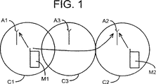
図1はチャネル間干渉の例を示す。この中で、移動局M1はセルC1内の基地局アンテナA1と通信しており、他方、移動局M2はセルC2内の基地局アンテナA2と通信している。セルC3を提供する基地局アンテナA3は、セルC1とセルC2の間に位置する。この例では、移動局はM1とM2は同時に同じチャネルで、異なるセル内の異なるアンテナへ通信している。図示されているように、移動局M1によってアンテナA1に送信される信号が移動局M2によってアンテナA2に送信される信号と干渉し、信号の減損を引き起こす。
このような信号の減損の影響を低減するために、受信器が多重分割アンテナを備え、各アンテナにおいて受信された信号が組み合わせられるダイバーシチイ組合せを使用することが知られている。アンテナは分割されているので、各アンテナ内の信号の強さは独立である。従って、1つのアンテナに深いフェージング・ディップ(fading dip)がある場合、他のアンテナは比較的強い信号を有する。ダイバーシチイ組合せ方法には多くの種類がある。たとえば、William C.Y.Lee (Wiley,1993)による「Mobile Communication Design Fundamentals」の116ページから132ページには、多くのダイバーシチイスキームが記述されている。
典型的な移動通信システムでは、アンテナのダイバーシチイは多重アンテナを備えた基地局を提供することによって利用されている。アンテナにおいて受信される信号は、典型的には、最大比組合せ(maximum ratio combining:MRC)を使用して組み合わせられる。例えば上記のLeeは、MRCを最良の組合せ技術として認識している。MRCでは、受信された信号は、干渉が白色ガウス雑音に密接に近似しているという仮定に基づいて組み合わされる。例として図2にMRCスキームを示すが、ここでは、各信号分岐(signal branch:すなわち、組み合わせるべき受信された各信号)は、選択された重み係数(α1、α2)によって重み付けられ、その信号分岐が組み合わされる。MRCは受信された信号間の相関は考慮していないため、受信された信号が、検出され、同時に1つずつ等化され、合計によって組み合わされることを可能にする。MRCは、信号によって受ける干渉が白色ガウス雑音に密接に近似していると仮定しているので、干渉が白色ガウス雑音にそれほど近似していない場合には、所定の性能限界(performance limitations)を有する。
代替案として、アンテナダイバーシチイを備えたシステムで受信された信号を組み合わせる改良された方法が、干渉阻止組合せ(interference rejection combining:IRC)として知られている。IRCは、受信された信号が白色ガウス雑音と他の送信器(他のセル内の他の移動局など)からの信号との両方を含むと仮定している。一般的に、IRCを組み込んだ受信機は、各アンテナについて受信信号のサンプルを生成し(例えば、対数極線信号処理(log-polar signal processing)などを使用して)、各アンテナについてチャネル・タップを推定し、減損相関特性(例えば、チャネル間干渉など)を推定し、受信信号サンプル、チャネル・タップの推定値、及び減損相関の推定値から分岐距離(branch metrics)を形成し、分岐距離を使用して送信された情報シーケンスを推定する(例えば、ビタビ・アルゴリズムなどを使用して)。受信器は、訓練用シーケンス(典型的なGSMバーストに含まれるような訓練用シーケンス)が受信された時、信号分岐の間での相関したノイズを推定することによって、損傷相関特性を推定する。この推定された共分散は、復調プロセスの間に受信器によって使用される。IRCは、特に、1994年8月2日に出願され本願の譲受人に譲渡された同時係属の米国特許出願第08/284775号「Method and Apparatus for Interference Rejection Combining in Multi−Antenna Digital Cellular Communications Systems」と、1996年4月19日に出願され本願の譲受人に譲渡された同時係属の米国特許出願第08/634719号「Method and Apparatus for Interference Rejection with Different Beams,Polarizations,and Phase References」に詳細に記述されている。これらの出願の全体が、参照により本明細書に組み込まれる。後者の特許出願は、減損相関特性がスカラー減損相関特性であり分岐距離がスカラー分岐距離である場合には、IRC性能を改良できることが開示されている。
IRCは、特に干渉バーストが搬送波バースト(すなわち、目的の送信された信号)と同期している場合には、目的の送信された信号と同じ周波数で送信している隣接するセルの移動局からの干渉(すなわち、チャネル間干渉)を非常に効率的に阻止できる。IRCはまた、隣接チャネルの干渉作用も低減する。残念なことに、IRCは複雑で、比較的大量のコンピュータ処理資源を必要とする。さらに、IRCが最適な性能を提供しない場合もいくつかある。
アンテナダイバーシチイを採用している通信システムの性能を向上させることが望まれている。特に、ダイバーシチイ組合せの既知の方法を改良することが望まれている。
発明の概要
本発明は、IRCとMRC(あるいは他のダイバーシチイ組合せ方法)を採用して多重アンテナから受信された信号を組み合わせるための方法とシステムを提供することにより、上記の問題を克服し、更に他の利点をも提供する。本発明の例示的な実施の形態によれば、送信器は1シーケンスの情報シンボルを表す信号を生成して送信する。多重アンテナを有する受信器は、少なくとも2つの受信信号があるように送信された信号を少なくとも2つのアンテナで受信する。受信器は、受信器の性能を最大にするために、干渉阻止組合せか最大比組合せかのどちらかを選択的に実行することにより、受信信号を組み合わせる。信号は、バーストごと、半バーストごと、又は他の適切な周波数で組み合わせることができる。IRCとMRCのどちらを使用するかを選択するために、受信器は干渉指標(interference indication)を決定し、組合せ方法は干渉指標に基づいて選択される。
IRC、従来のダイバーシチイ組合せスキーム、あるいは複数のスキームの組合せを選択的に実行することによって、本発明は、通信システムにIRCがもっとも適切な時(すなわち、干渉が主にチャネル間干渉の場合)、隣接チャネル干渉の時、あるいはダイバーシチイ分岐の間の他の相関時に、IRCの利点を達成させることを可能にし、IRCが適切でない時(すなわち、チャネル間干渉が比較的低く、干渉が白色ガウス雑音により密接に近似している時)には、処理リソースを省くことを可能にする。この選択的組合せスキームは、通信の効率を非常に高める。たとえば、以下に論じるように、本発明はIRCだけを使用したシステムに比べて、性能で1dBのゲインを達成することを可能にする。
【図面の簡単な説明】
本発明のさらに完全な理解は、付随する図面を参照しながら以下の好ましい実施の形態の詳細な説明を読むことによって得られる。この図面では同様の要素を示すために同じ参照記号を使用している。
図1は、チャネル間干渉の例を示す図である。
図2は、MRCを使用したダイバーシチイ組合せ技術を示す構成図である。
図3は、本発明の好ましい実施の形態の実装を示す構成図である。
図4は、本発明による方法の好ましい実施の形態を記述するフローチャートである。
図5は、本発明の第2の例示的な実施の形態を示す構成図である。
図6は、図3の実施の形態と図5の実施の形態との例示的組合せを示す構成図である。
図7は、本発明の別の実施の形態の構成図である。
図8は、図7の実施の形態の変形例の構成図である。
図9は、図5の実施の形態によるIRCとMRCとの組合せを使用した受信器の性能結果を比較したグラフを示す図である。
図10は、図3の実施の形態の性能結果を比較したグラフを示す図である。
好ましい実施の形態の詳細な説明
図3は、本発明の第1の例示的な実施の形態を示す構成図である。アンテナ10と12は、アンテナダイバーシチイを採用した受信器の多重アンテナのうちの2つであり、移動局あるいは別の送信器(図示せず)から送信された信号を受信する。組合わせモジュール14と16は、それぞれアンテナ10と12から受信信号を受信するように接続される。組合わせモジュール14と16は、それぞれMRC(又は他の既存のダイバーシチイ組合せ技術)とIRCを使用してアンテナ10と12から受信された信号を組み合わせる能力と、組み合わせた信号を復号器又は他の信号処理回路(図示せず)に出力する能力とを持つ。適切な組合わせモジュール14又は16は、干渉分析器18によって起動され、この干渉分析器18が受信された信号が受けた干渉が所定の閾値を超えているか否かを決定し、スイッチ19を使用して適切な組合わせモジュールを選択する。閾値が一致しているか超えているかを決定するために、分析器18は各受信された信号について2つの分岐の間の相関を推定し、推定された相関を相関閾値を比較する。たとえば、減損相関マトリックスを形成し、減損相関マトリックスのオフ対角要素(off-diagonal elements)を使用して相関と干渉とを測定することができる。適切な閾値はマトリックスの対角要素から抽出できる。減損相関マトリックスは、本願の譲渡人に譲渡された同時係属の米国特許出願第08/284775号「Method and Apparatus for Interference Rejection Combining in Multi−Antenna Digital Cellular Commnuications Systems」に詳細に論じられており、この出願全体は参照により本明細書に組み込まれる。他の多くの閾値計算と比較スキームとを使用することができる。干渉バーストが目的の送信された信号の搬送波バーストと同期している場合には、推定された相関はバーストの間一定である。より一般的であるが、干渉バーストが搬送波バーストと同期していない場合には、推定された相関はバーストの間一定ではない。干渉(あるいは他の適切な減損特性)が所定の閾値に一致するか所定の閾値を超えた場合、干渉分析器18はIRC組合わせモジュール16を選択する。干渉(あるいは他の適切な減損特性)が所定の閾値に一致しないあるいは所定の閾値を超えない場合、干渉分析器18はMRC組合わせモジュール14を選択する。選択されたモジュールは、組み合わせられた信号をさらに処理するために、受信器の中の復号器(図示せず)に出力する。図3の回路を動作させ、バーストごと、半バーストごと、又は他の適切な間隔で受信された信号を組み合わせることができる。
図4は、本発明による方法のステップを記述するフローチャートである。ステップ100で、受信器は移動局あるいは他の送信器によって送信された信号を多重アンテナ上で受信する。ステップ102で、受信器(分析器18あるいは他の適切な手段などを使用する)は受信された信号を分析し、干渉のレベルが所定の閾値に一致しているかあるいは超えているかを決定する。ステップ102で使用された干渉閾値が受信された信号に一致するか又は受信された信号によって超えられている場合は、受信器はステップ104でIRCを使用して複数の受信された信号を組み合わせる。また、ステップ102で使用された干渉閾値が受信された信号に一致しないか受信された信号によって超えられていない場合は、受信器はステップ106でMRC(あるいは別の適切なダイバーシチイ組合せ技術)を使用して複数の受信された信号を組み合わせる。どららの組合せ方法を使用しても、所定の間隔後にプロセスはステップ100に戻り、他の受信された信号を処理する。所定の間隔は、バーストごと、半バーストごと、あるいは別の適切な間隔のどれでも可能である。この結果、適切なダイバーシチイ組合せ技術が各間隔について選択できる。
図5は、本発明の第2の例示的な実施の形態を示す構成図である。この実施の形態では、MRCとIRCとの両方を使用して分岐を組み合わせ、次に組合わせモジュール14と16との出力が、各組合せアルゴリズムからの出力を最適化するように組合器20内で組み合わせられる。組合器20は、各バースト、半バースト、あるいは他の適切な期間ごとに、MRC出力とIRC出力とを組み合わせることができる。図5の実施の形態は、特に、干渉が存在し、搬送波バーストと干渉バーストとが同期していない場合に利点が大きい。
こうして、図3の実施の形態では、干渉が存在しない時にIRCだけを使用するよりも改良された性能を提供し、図5の実施の形態では、干渉が存在し干渉バーストが搬送波バーストと同期していない時に改良された性能を提供する。図3と図5との実施の形態は、両方の実施の形態の性能を最大にするために組み合わせることができる。これらの実施の形態を組み合わせた例が図6に示されており、この中で分析器18は入力信号を分析し、スイッチ19を介して、干渉指標に基づき組合器20の出力あるいはMRC組合わせモジュール14の出力のどちらかを選択する。
図7は、信号バーストを格納するためのメモリ22aと22b、格納されたバーストを分析するための分析器18、分析器18の出力に依存した方法で信号を組み合わせるための組合器20を含む、本発明のさらに他の実施の形態を示す。この実施の形態の中で、分析器18は受信されたバーストに関連した干渉のレベルに基づいて値αを決定する。値αは、異なるダイバーシチイ組合せ技術にどれくらいの重み付けを割り当てるかを決定する重み係数である。たとえば、IRCが好ましい組合せ技術であるような干渉レベルの時には、分析器18によって係数1を割り当てる。α係数が1の間、組合器20はIRCを使用する。別のダイバーシチイ組合せ技術(たとえばMRC)が好ましいような干渉レベルの時には、α係数に0を割り当てる。α係数が0の間、組合器20はMRCを使用する。IRCを50%、MRCを50%で重み付けされた組合せが好ましいような干渉レベルの時には、0.5のα係数を割り当てる。α係数が0.5の間、IRCとMRCの両方が実行され、結果が均等に組み合わせられる。α係数が0.75の間、IRCとMRCの両方が実行され、IRCの結果とMRCの結果を3/1の比で重み付けすることによって結果が組み合わせられる。この実施の形態では、組合せ技術の「柔らかい(soft)」あるいは除々の移動が達成できる。この実施の形態では、組合器20はプログラム可能な組合器によって達成される。
図8は、図7の実施の形態の変形例である。図8の実施の形態では、受信されたバーストはメモリ22aと22bに格納される。分析器18は干渉のレベルを決定し、適切なα値を割り当てる。組合器20は格納されたバーストを分析器の出力に依存するような方法で組み合わせ、組合器20の出力はメモリ22cに格納される。次に分析器18はαをたとえば0にリセットし、第2の組合せを実行する。この第2の組合せの出力は、次に、組合器24のメモリ22cに格納された第1の組合せ結果と組み合わせられる。当業者には、他の多くの変形例が容易に分かるであろう。
図9は、図5の実施の形態について、ビット・エラー・レート(BER)を通信チャネルの干渉遅延の関数として比較したグラフである。図9のグラフでは、IRCとMRCの組合せ(IRC-MRC)は、バーストごとに(すなわち、バーストごとのベースで)受信された信号を組み合わせることによって達成されている。さらに、信号対雑音比(SNR)は25dBと仮定され、搬送波対干渉比(C/I)は2dBと仮定されている。グラフから分かるように、IRCとMRCの組合せはIRCだけを使用した受信器に比べて、性能を改良することができる。
図10は、図3の実施の形態について、ビット・エラー・レートを信号対雑音比(SNR)の関数として比較したグラフであり、ここでIRCアルゴリズムは、チャネル間干渉が存在しない期間はスイッチが切られているか選択されていない。図示されているように、IRCが常に使用されている場合に比べて、感度において約1dBのゲインを得ることが可能である。
このように、本発明は、既知のダイバーシチイ組合せ技術に比べて大きな利点を提供することは明らかである。特に、IRCとMRCあるいは別の適切なダイバーシチイ組合せ技術を選択的に使用することにより、1種類だけのダイバーシチイ組合せ技術を使用した受信器に比べて受信器の性能を向上させることができる。本発明の原理は、3種類以上の異なる組合せ技術を使用したシステムにも適用できることに注意されたい。
上記の説明は多くの詳細と限定とを含むが、これらは説明のためにすぎないことを理解されたい。当業者であれば、多くの変形が、下記の請求の範囲及びその正当な均等物で定義される本発明の精神及び範囲に含まれることは明らかであろう。すなわち、3種類以上の異なったダイバーシチイ組合せ技術も組み合わせることが可能である。 Field of the Invention The present invention relates generally to the processing of digitally modulated radio signals in receivers having multiple antennas, and in particular, diversity combining of radio signals to reduce signal impairment. About.
Background of the invention In wireless communication, signals may be lost or impaired due to various phenomena such as multipath fading, time dispersion, and intersymbol interference that exist in typical wireless communication channels. . Multipath fading results from the interaction of transmitted signals that reach the receiver almost simultaneously with their reflections or echoes. When the number of reflections is relatively large, this fading exhibits a so-called Rayleigh distribution. Time dispersion occurs when there is a time delay between the reflection and the transmitted signal. Interference results from the presence of signals that are not orthogonal with respect to the transmitted signal. Such non-orthogonal signals can arise from other radios operating at the same frequency (interchannel interference) or from other radios operating in adjacent frequency bands (adjacent channel interference).
FIG. 1 shows an example of interchannel interference. Among these, the mobile station M1 is communicating with the base station antenna A1 in the cell C1, while the mobile station M2 is communicating with the base station antenna A2 in the cell C2. The base station antenna A3 that provides the cell C3 is located between the cells C1 and C2. In this example, the mobile station is communicating to different antennas in different cells, with M1 and M2 simultaneously on the same channel. As shown, the signal transmitted by the mobile station M1 to the antenna A1 interferes with the signal transmitted by the mobile station M2 to the antenna A2, causing signal impairment.
In order to reduce the influence of such signal impairment, it is known that the receiver includes a multi-division antenna and uses a diversity combination in which signals received at each antenna are combined. Since the antennas are divided, the signal strength within each antenna is independent. Thus, if one antenna has a deep fading dip, the other antenna has a relatively strong signal. There are many types of diversity combination methods. For example, William C.I. Y. A number of diversity schemes are described on pages 116 to 132 of “Mobile Communication Design Fundamentals” by Lee (Wiley, 1993).
In a typical mobile communication system, antenna diversity is utilized by providing a base station with multiple antennas. Signals received at the antenna are typically combined using a maximum ratio combining (MRC). For example, the above Lee recognizes MRC as the best combination technique. In MRC, the received signals are combined based on the assumption that the interference closely approximates white Gaussian noise. As an example, FIG. 2 shows the MRC scheme, where each signal branch (ie, each received signal to be combined) is weighted by a selected weighting factor (α 1 , α 2 ) Signal branches are combined. Since MRC does not consider the correlation between the received signals, it allows the received signals to be detected and equalized one at a time and combined by summation. Since the MRC assumes that the interference received by the signal closely approximates white Gaussian noise, it has certain performance limitations when the interference is not very close to white Gaussian noise. .
As an alternative, an improved method of combining signals received in a system with antenna diversity is known as interference rejection combining (IRC). IRC assumes that the received signal includes both white Gaussian noise and signals from other transmitters (such as other mobile stations in other cells). In general, receivers incorporating IRC generate a sample of the received signal for each antenna (eg, using log-polar signal processing, etc.) and channel taps for each antenna. , Estimate impairment correlation characteristics (eg inter-channel interference), form branch metrics from received signal samples, channel tap estimates, and impairment correlation estimates, To estimate the transmitted information sequence (eg, using a Viterbi algorithm, etc.). The receiver estimates the damage correlation characteristics by estimating the correlated noise between the signal branches when a training sequence (a training sequence as included in a typical GSM burst) is received. This estimated covariance is used by the receiver during the demodulation process. In particular, IRC is a co-pending U.S. patent application Ser. No. 08 / 284,775 filed Aug. 2, 1994 and assigned to the assignee of the present application, “Method and Apparatus for Interference Combining in Multi-Antenna Digital Stimulation”. And co-pending U.S. patent application Ser. No. 08/634719 filed Apr. 19, 1996, assigned to the assignee of the present application, “Method and Apparatus for Interference Resistance with Different Beams, Polarizations, and Phases”. is described. The entirety of these applications is incorporated herein by reference. The latter patent application discloses that IRC performance can be improved when the impairment correlation characteristic is a scalar impairment correlation characteristic and the branch distance is a scalar branch distance.
The IRC is based on mobile stations in adjacent cells that are transmitting on the same frequency as the intended transmitted signal, especially when the interference burst is synchronized with the carrier burst (ie, the intended transmitted signal). Interference (ie inter-channel interference) can be blocked very efficiently. IRC also reduces adjacent channel interference effects. Unfortunately, IRC is complex and requires a relatively large amount of computer processing resources. In addition, there are some cases where IRC does not provide optimal performance.
It is desired to improve the performance of a communication system that employs antenna diversity. In particular, it is desirable to improve the known methods of diversity combination.
SUMMARY OF THE INVENTION The present invention provides a method and system for combining signals received from multiple antennas employing IRC and MRC (or other diversity combining methods) to overcome the above problems. And provides other advantages. According to an exemplary embodiment of the invention, the transmitter generates and transmits a signal representing a sequence of information symbols. A receiver having multiple antennas receives a transmitted signal with at least two antennas such that there are at least two received signals. The receiver combines the received signals by selectively performing either an interference blocking combination or a maximum ratio combination to maximize receiver performance. The signals can be combined at every burst, every half-burst, or other suitable frequency. To select whether to use IRC or MRC, the receiver determines an interference indication and a combination method is selected based on the interference indication.
By selectively implementing IRC, a conventional diversity combination scheme, or a combination of schemes, the present invention allows the IRC to be most appropriate for a communication system (ie, when the interference is primarily interchannel interference). Allows the benefits of IRC to be achieved during adjacent channel interference, or during other correlations between diversity branches, when IRC is not appropriate (ie, interchannel interference is relatively low and interference is white Gaussian When closer to noise), it makes it possible to save processing resources. This selective combination scheme greatly increases the efficiency of communication. For example, as discussed below, the present invention makes it possible to achieve a gain of 1 dB in performance compared to a system using only IRC.
[Brief description of the drawings]
A more complete understanding of the invention can be obtained by reading the following detailed description of the preferred embodiment with reference to the accompanying drawings. In the drawings, the same reference symbols are used to indicate similar elements.
FIG. 1 is a diagram illustrating an example of interchannel interference.
FIG. 2 is a block diagram showing a diversity combination technique using MRC.
FIG. 3 is a block diagram illustrating the implementation of the preferred embodiment of the present invention.
FIG. 4 is a flowchart describing a preferred embodiment of the method according to the invention.
FIG. 5 is a block diagram showing a second exemplary embodiment of the present invention.
6 is a block diagram showing an exemplary combination of the embodiment of FIG. 3 and the embodiment of FIG.
FIG. 7 is a configuration diagram of another embodiment of the present invention.
FIG. 8 is a configuration diagram of a modification of the embodiment of FIG.
FIG. 9 is a diagram showing a graph comparing the performance results of a receiver using a combination of IRC and MRC according to the embodiment of FIG.
FIG. 10 is a diagram showing a graph comparing the performance results of the embodiment of FIG.
Detailed Description of Preferred Embodiments FIG. 3 is a block diagram illustrating a first exemplary embodiment of the present invention.
FIG. 4 is a flowchart describing the steps of the method according to the invention. In
FIG. 5 is a block diagram showing a second exemplary embodiment of the present invention. In this embodiment, both MRC and IRC are used to combine branches, and then the outputs of
Thus, the embodiment of FIG. 3 provides improved performance over using IRC alone when there is no interference, and in the embodiment of FIG. 5, the interference is present and the interference burst is synchronized with the carrier burst. Provides improved performance when not. The embodiments of FIGS. 3 and 5 can be combined to maximize the performance of both embodiments. An example of a combination of these embodiments is shown in FIG. 6, in which the
FIG. 7 includes
FIG. 8 is a modification of the embodiment of FIG. In the embodiment of FIG. 8, received bursts are stored in
FIG. 9 is a graph comparing the bit error rate (BER) as a function of the interference delay of the communication channel for the embodiment of FIG. In the graph of FIG. 9, the combination of IRC and MRC (IRC-MRC) is achieved by combining received signals on a burst-by-burst basis (ie, on a per-burst basis). Furthermore, the signal to noise ratio (SNR) is assumed to be 25 dB and the carrier to interference ratio (C / I) is assumed to be 2 dB. As can be seen from the graph, the combination of IRC and MRC can improve performance compared to a receiver using only IRC.
FIG. 10 is a graph comparing the bit error rate as a function of signal-to-noise ratio (SNR) for the embodiment of FIG. 3, where the IRC algorithm does not switch during periods when there is no interchannel interference. It is cut or not selected. As shown in the figure, it is possible to obtain a gain of about 1 dB in sensitivity compared to the case where IRC is always used.
Thus, it is clear that the present invention provides significant advantages over known diversity combination techniques. In particular, by selectively using IRC and MRC or another suitable diversity combination technique, the performance of the receiver can be improved as compared to a receiver using only one type of diversity combination technique. It should be noted that the principles of the present invention can be applied to systems using more than two different combination techniques.
While the above description includes many details and limitations, it should be understood that these are for illustration purposes only. It will be apparent to those skilled in the art that many variations are within the spirit and scope of the invention as defined by the following claims and their legal equivalents. That is, it is possible to combine three or more different diversity combination techniques.
Claims (23)
少なくとも2つの受信信号が存在するように、少なくとも2つのアンテナで送信された信号を受信するステップと、
干渉レベルを測定するステップと、
前記干渉レベルが所定の閾値を越えることにより干渉が主にチャネル間干渉と判断される場合は、干渉阻止組合せ(IRC)を使用して前記受信した信号を組み合わせるステップと、
前記干渉レベルが所定の閾値を越えない場合は、他のダイバーシチイ組合せ方法を使用して前記受信した信号を組み合わせるステップとを含むことを特徴とする方法。A method for combining diversity in a wireless communication system, comprising:
Receiving signals transmitted on at least two antennas such that there are at least two received signals;
Measuring the interference level;
Combining the received signals using an interference rejection combination (IRC) if the interference level is determined to be primarily inter-channel interference due to the interference level exceeding a predetermined threshold;
Combining the received signals using another diversity combining method if the interference level does not exceed a predetermined threshold.
少なくとも2つの受信信号が存在するように、少なくとも2つのアンテナで送信された信号を受信するステップと、
第1の結果を得るために干渉阻止組合せ(IRC)を使用し、第2の結果を得るために他のダイバーシチイ組合せ方法を使用して、前記受信した信号を組み合わせるステップと、
前記第1及び第2の結果を、干渉レベルに基づいて変化する重み係数により重み付けして組み合わせるステップとを含むことを特徴とする方法。A method for combining diversity in a wireless communication system, comprising:
Receiving signals transmitted on at least two antennas such that there are at least two received signals;
Combining the received signals using an interference rejection combination (IRC) to obtain a first result and using other diversity combining methods to obtain a second result;
Combining the first and second results by weighting with a weighting factor that varies based on an interference level .
各アンテナについて受信信号のサンプルを生成し、
各アンテナについてチャネル・タップを推定し、
アンテナ間での減損相関特性を推定し、
前記受信信号サンプル、チャネル・タップ推定値、及び減損相関推定値から分岐距離を形成し、
前記分岐距離を使用して情報シーケンスを推定することによって実行されることを特徴とする請求項1に記載の方法。The interference blocking combination is:
Generate a sample of the received signal for each antenna,
Estimate channel taps for each antenna,
Estimate the impairment correlation between antennas,
Forming a branch distance from the received signal samples, channel tap estimates, and impairment correlation estimates;
The method of claim 1, wherein the method is performed by estimating an information sequence using the branch distance.
干渉レベルに基づいて変化する重み係数を決定するステップと、
干渉阻止組合せ(IRC)と他のダイバーシチイ組合せ方法との重み付けされた組合せを使用して、前記受信した信号を組み合わせるステップとを含むことを特徴とする請求項4に記載の方法。Combining the first and second results comprises:
Determining a weighting factor that changes based on the interference level;
5. The method of claim 4, comprising combining the received signals using a weighted combination of interference rejection combinations (IRCs) and other diversity combining methods.
複数の受信信号が存在するように通信信号を受信するための複数のアンテナと、
それぞれの信号組合器が複数のアンテナの各々に関連して、前記受信信号を組み合わせる複数の信号組合器であって、干渉阻止組合せ(IRC)を使用する第1の信号組合器と他のダイバーシチイ組合せ技術を使用する第2の信号組合器とを含む複数の信号組合器と、
信号減損のレベルを決定し、信号減損の前記レベルを閾値レベルと比較し、前記比較に基づいて前記複数の信号組合器を選択的に動作させる分析手段であって、前記レベルが閾値レベルを越えることにより干渉が主にチャネル間干渉と判断される場合は前記第1の信号組合器を動作させ、前記レベルが閾値レベルを越えない場合は前記第2の信号組合器を動作させる分析手段とを含むことを特徴とするシステム。A system for receiving a communication signal,
A plurality of antennas for receiving communication signals such that there are a plurality of received signals;
A plurality of signal combiners that combine the received signals with each signal combiner associated with each of a plurality of antennas, the first signal combiner using interference blocking combination (IRC) and other diversity combinations. A plurality of signal combiners, including a second signal combiner using a combination technique;
Analysis means for determining a level of signal impairment, comparing the level of signal impairment with a threshold level, and selectively operating the plurality of signal combiners based on the comparison , wherein the level exceeds the threshold level An analysis means for operating the first signal combiner when the interference is mainly determined as inter-channel interference, and operating the second signal combiner when the level does not exceed a threshold level. A system characterized by including.
各アンテナごとに受信信号のサンプルを生成し、
各アンテナごとにチャネル・タップを推定し、
アンテナ間の減損相関特性を推定し、
前記受信信号サンプル、チャネル・タップ推定値、及び減損相関推定値から分岐距離を形成し、
前記分岐距離を使用して情報シーケンスを推定することを特徴とする請求項12に記載のシステム。The first signal combiner is
Generate a sample of the received signal for each antenna,
Estimate channel taps for each antenna,
Estimate the impairment correlation characteristics between antennas,
Forming a branch distance from the received signal samples, channel tap estimates, and impairment correlation estimates;
13. The system of claim 12, wherein the information sequence is estimated using the branch distance.
複数の受信信号が存在するように通信信号を受信するための複数のアンテナと、
それぞれの信号組合器が複数の信号組合せ技術のうちの異なる1つの技術を使用して受信した信号を組み合わせる複数の信号組合器であって、前記複数の信号組合せ技術のうちの1つが干渉阻止組合せ(IRC)である複数の信号組合器と、
前記複数の信号組合器のうちの少なくとも選択された信号組合器の出力を組み合わせるための組合器であって、信号減損のレベルに基づいて変化する重み係数により重み付けた前記信号組合器の出力を組み合わせるための組合器とを含むことを特徴とするシステム。A system for receiving a communication signal,
A plurality of antennas for receiving communication signals such that there are a plurality of received signals;
A plurality of signal combiners, each signal combiner combining signals received using a different one of the plurality of signal combination techniques, wherein one of the plurality of signal combination techniques is an interference blocking combination A plurality of signal combiners being (IRC);
A combiner for combining the outputs of at least selected signal combiners of the plurality of signal combiners, wherein the outputs of the signal combiners are weighted by a weighting factor that varies based on the level of signal impairment. A system characterized by comprising a combination device for the purpose .
複数の受信信号が存在するように通信信号を受信するための複数のアンテナと、
前記受信信号と関連する干渉指標を決定し、前記干渉指標に基づいて変化する重み係数を選択するための分析器と、
前記干渉指標に基づいて変化する重み係数に基づいて、少なくとも2つの信号組合せ技術の重み付けされた組合せを実行するための第1の信号組合器であって、前記信号組合せ技術の1つが干渉阻止組合せ(IRC)である第1の信号組合器とを含むことを特徴とする含むシステム。A system for receiving a communication signal,
A plurality of antennas for receiving communication signals such that there are a plurality of received signals;
An analyzer for determining an interference metric associated with the received signal and selecting a weighting factor that changes based on the interference metric;
A first signal combiner for performing a weighted combination of at least two signal combination techniques based on a weighting factor that varies based on the interference indicator, wherein one of the signal combination techniques is an interference blocking combination A first signal combiner that is (IRC).
格納された前記第1の出力と前記第1の信号組合器の第2の出力とを組み合わせるための第2の信号組合器とを更に含むことを特徴とする請求項22に記載のシステム。A combiner output memory for storing a first output of the first signal combiner;
23. The system of claim 22, further comprising a second signal combiner for combining the stored first output and the second output of the first signal combiner.
Applications Claiming Priority (3)
| Application Number | Priority Date | Filing Date | Title |
|---|---|---|---|
| US08/861,541 US6128355A (en) | 1997-05-21 | 1997-05-21 | Selective diversity combining |
| US08/861,541 | 1997-05-21 | ||
| PCT/SE1998/000876 WO1998053560A1 (en) | 1997-05-21 | 1998-05-12 | Selective diversity combining |
Publications (3)
| Publication Number | Publication Date |
|---|---|
| JP2002508898A JP2002508898A (en) | 2002-03-19 |
| JP2002508898A5 JP2002508898A5 (en) | 2005-12-08 |
| JP4312836B2 true JP4312836B2 (en) | 2009-08-12 |
Family
ID=25336090
Family Applications (1)
| Application Number | Title | Priority Date | Filing Date |
|---|---|---|---|
| JP55028098A Expired - Lifetime JP4312836B2 (en) | 1997-05-21 | 1998-05-12 | Selective diversity combination |
Country Status (9)
| Country | Link |
|---|---|
| US (1) | US6128355A (en) |
| EP (1) | EP0983644B1 (en) |
| JP (1) | JP4312836B2 (en) |
| CN (1) | CN1123145C (en) |
| AU (1) | AU739043B2 (en) |
| BR (1) | BR9809856B1 (en) |
| CA (1) | CA2290467C (en) |
| DE (1) | DE69834178T2 (en) |
| WO (1) | WO1998053560A1 (en) |
Families Citing this family (81)
| Publication number | Priority date | Publication date | Assignee | Title |
|---|---|---|---|---|
| US6173014B1 (en) * | 1994-08-02 | 2001-01-09 | Telefonaktiebolaget Lm Ericsson | Method of and apparatus for interference rejection combining and downlink beamforming in a cellular radio communications system |
| US6185258B1 (en) | 1997-09-16 | 2001-02-06 | At&T Wireless Services Inc. | Transmitter diversity technique for wireless communications |
| EP2285011B8 (en) | 1997-10-31 | 2018-06-27 | AT&T Mobility II LLC | Maximum likelihood detection of concatenated space codes for wireless applications |
| FR2777720B1 (en) * | 1998-04-16 | 2000-05-26 | Alsthom Cge Alcatel | DIVERSITY RECEIVER |
| DE19833967C2 (en) * | 1998-07-28 | 2001-02-08 | Siemens Ag | Reception diversity procedure and radio communication system with diversity reception |
| US20020150070A1 (en) * | 1999-07-02 | 2002-10-17 | Shattil Steve J. | Method and apparatus for using frequency diversity to separate wireless communication signals |
| AU2001243626A1 (en) * | 2000-03-17 | 2001-10-03 | Wireless Online, Inc. | Method and system for detecting signals |
| EP1150441B1 (en) * | 2000-04-25 | 2014-03-26 | Alcatel Lucent | Method and receiver for combining at least two received signals of a telecommunication system |
| DE60019091T2 (en) * | 2000-05-05 | 2006-02-02 | Lucent Technologies Inc. | Radio communication system |
| US6701165B1 (en) * | 2000-06-21 | 2004-03-02 | Agere Systems Inc. | Method and apparatus for reducing interference in non-stationary subscriber radio units using flexible beam selection |
| DE10031677B4 (en) * | 2000-06-29 | 2005-09-29 | Siemens Ag | Method or communication system with robust diversity combining |
| GB2364210A (en) * | 2000-06-30 | 2002-01-16 | Nokia Oy Ab | Diversity receiver and method of receiving a multi carrier signal |
| JP4818568B2 (en) * | 2000-12-04 | 2011-11-16 | 三菱電機株式会社 | Composite reception method and composite reception apparatus |
| FI20002844A (en) * | 2000-12-22 | 2002-06-23 | Nokia Corp | Measurement procedure and receiver |
| US7065146B1 (en) | 2002-02-15 | 2006-06-20 | Marvell International Ltd. | Method and apparatus for equalization and decoding in a wireless communications system including plural receiver antennae |
| US7039140B2 (en) * | 2001-03-08 | 2006-05-02 | Proxim Wireless Corporation | OFDM data demodulators synchronization |
| GB0107113D0 (en) * | 2001-03-21 | 2001-05-09 | Nokia Networks Oy | Interference rejection in a receiver |
| US6999538B2 (en) * | 2001-09-10 | 2006-02-14 | Mitsubishi Electric Research Laboratories, Inc. | Dynamic diversity combiner with associative memory model for recovering signals in communication systems |
| US7567634B1 (en) | 2002-02-15 | 2009-07-28 | Marvell International Ltd. | Reduced complexity viterbi decoding method and apparatus |
| WO2003073630A1 (en) * | 2002-02-28 | 2003-09-04 | Telefonaktiebolaget Lm Ericsson | Signal receiver devices and methods |
| US7065383B1 (en) | 2002-04-16 | 2006-06-20 | Omri Hovers | Method and apparatus for synchronizing a smart antenna apparatus with a base station transceiver |
| US7529525B1 (en) | 2002-04-16 | 2009-05-05 | Faulkner Interstices Llc | Method and apparatus for collecting information for use in a smart antenna system |
| US7346365B1 (en) | 2002-04-16 | 2008-03-18 | Faulkner Interstices Llc | Smart antenna system and method |
| TWM240732U (en) * | 2002-08-07 | 2004-08-11 | Interdigital Tech Corp | Base station using closed loop transmit diversity of point to multipoint physical channels |
| DE10243345B4 (en) * | 2002-09-18 | 2011-02-17 | Siemens Ag | Method and device for transmitting data |
| GB0222046D0 (en) * | 2002-09-23 | 2002-10-30 | Nokia Corp | Receiving method and receiver |
| FI20031609A0 (en) * | 2003-11-06 | 2003-11-06 | Nokia Corp | Communication method, receiver and base station |
| US7395079B2 (en) * | 2004-05-04 | 2008-07-01 | Telefonaktiebolaget L M Ericsson (Publ) | Methods and apparatus for selectively processing information replicas |
| KR100833337B1 (en) | 2004-06-16 | 2008-05-29 | 선라이즈 텔레콤 인코포레이티드 | Qam signal analysis in a network |
| US20050281200A1 (en) * | 2004-06-16 | 2005-12-22 | Gerard Terreault | QAM signal analysis in a network |
| WO2006000950A1 (en) * | 2004-06-24 | 2006-01-05 | Koninklijke Philips Electronics N.V. | Noise canceling in equalized signals |
| US7324794B2 (en) * | 2004-09-29 | 2008-01-29 | Tzero Technologies, Inc. | Phase combining diversity |
| US7715806B2 (en) | 2004-10-06 | 2010-05-11 | Broadcom Corporation | Method and system for diversity processing including using dedicated pilot method for closed loop |
| US7643839B2 (en) * | 2004-10-06 | 2010-01-05 | Broadcom Corporation | Method and system for diversity processing |
| US7505539B2 (en) * | 2004-10-06 | 2009-03-17 | Broadcom Corporation | Method and system for single antenna receiver system for HSDPA |
| CN100359822C (en) * | 2004-10-14 | 2008-01-02 | 中兴通讯股份有限公司 | Method and device for treating emission diversity selected by antenna |
| US8279985B2 (en) * | 2005-02-22 | 2012-10-02 | Adaptix, Inc. | Intelligent demodulation systems and methods in an OFDMA multicell network |
| US7796956B2 (en) * | 2005-05-03 | 2010-09-14 | Telefonaktiebolaget L M Ericsson (Publ) | Receiver for a multi-antenna, multi-band radio |
| CN100544231C (en) * | 2005-06-08 | 2009-09-23 | 中兴通讯股份有限公司 | Smart antenna implementation method and smart antenna based on software radio are realized system |
| US20070009069A1 (en) * | 2005-07-06 | 2007-01-11 | Ning Kong | Method operable to determine a signal to noise ratio gap between selection combining and maximal ratio combining for an arbitrary number of diversity branches |
| US8223904B2 (en) * | 2005-08-22 | 2012-07-17 | Qualcomm Incorporated | Multiple hypothesis decoding |
| JP4732161B2 (en) * | 2005-12-27 | 2011-07-27 | 京セラ株式会社 | Wireless communication apparatus and wireless communication control method |
| KR100975701B1 (en) * | 2006-01-26 | 2010-08-12 | 삼성전자주식회사 | Apparatus and method for controlling dynamic range of weight vectors according to combining methods in a mobile station equipped with multiple antennas in high rate packet data system using code division multiple access scheme |
| US20070242666A1 (en) * | 2006-04-13 | 2007-10-18 | Alcatel | Apparatus for managing requests for data in a communication network |
| US7944996B2 (en) * | 2006-06-07 | 2011-05-17 | Panasonic Corporation | OFDM reception device and OFDM receiver using the same |
| JP4679467B2 (en) * | 2006-08-21 | 2011-04-27 | 株式会社東芝 | Signal receiving system and signal receiving method |
| JP4399672B2 (en) * | 2006-08-30 | 2010-01-20 | 京セラ株式会社 | Communication apparatus and control method |
| WO2008056224A2 (en) * | 2006-11-06 | 2008-05-15 | Nokia Corporation | Apparatus, methods, and computer program products providing reduced interference in a multi-antenna system |
| KR100950655B1 (en) * | 2006-12-20 | 2010-04-01 | 삼성전자주식회사 | Method and apparatus for receiving data using a plurality of antennas in communication system |
| US9253009B2 (en) * | 2007-01-05 | 2016-02-02 | Qualcomm Incorporated | High performance station |
| DE602007003072D1 (en) * | 2007-02-05 | 2009-12-17 | Research In Motion Ltd | Multi-mode receiver with adaptive mode selection |
| US7826574B2 (en) * | 2007-02-05 | 2010-11-02 | Research In Motion Limited | Multi-mode receiver with adaptive mode selection |
| US8666004B2 (en) * | 2008-05-21 | 2014-03-04 | Qualcomm Incorporated | Methods and systems for hybrid MIMO schemes in OFDM/A systems |
| CN101667845B (en) * | 2008-09-05 | 2013-03-20 | 中兴通讯股份有限公司 | Self-adapting combination method and self-adapting combination system for multi-channel signals |
| WO2010121657A1 (en) * | 2009-04-22 | 2010-10-28 | Nokia Siemens Networks Oy | Selective interference rejection combining |
| US8396438B2 (en) * | 2009-06-24 | 2013-03-12 | Qualcomm Incorporated | Enhanced interference nulling equalization |
| CN101729486B (en) * | 2009-12-24 | 2015-04-29 | 北京韦加航通科技有限责任公司 | Method and system for double-antenna receiving diversity in single carrier frequency domain equalization system |
| GB2479549B (en) * | 2010-04-13 | 2012-10-03 | Toshiba Res Europ Ltd | Low complexity antenna selection methods for interference rejection receivers |
| EP2633635B1 (en) * | 2010-10-29 | 2017-08-09 | Telefonaktiebolaget LM Ericsson (publ) | Method and arrangement for interference mitigation |
| US8818306B2 (en) * | 2010-12-22 | 2014-08-26 | Sharp Kabushiki Kaisha | Wireless communication device |
| CN102638423A (en) * | 2011-02-11 | 2012-08-15 | 中兴通讯股份有限公司 | Interference and noise elimination method and device |
| JP5432208B2 (en) * | 2011-04-25 | 2014-03-05 | 株式会社Nttドコモ | Mobile communication terminal |
| CN102324960A (en) * | 2011-05-13 | 2012-01-18 | 中兴通讯股份有限公司 | Interference suppression merging method and receiver |
| US8537926B2 (en) * | 2011-06-08 | 2013-09-17 | Xg Technology, Inc. | Cognitive receiver architecture |
| CN103095316A (en) * | 2011-10-27 | 2013-05-08 | 京信通信系统(中国)有限公司 | Self-adaption interference rejection method and device thereof |
| US8831546B2 (en) | 2011-11-07 | 2014-09-09 | Ibiquity Digital Corporation | MRC antenna diversity for FM IBOC digital signals |
| GB2502308B (en) * | 2012-05-22 | 2014-09-17 | Toshiba Res Europ Ltd | A transceiver, system and method for selecting an antenna |
| CN103516412B (en) * | 2012-06-28 | 2017-03-08 | 联芯科技有限公司 | The multiple-input and multiple-output detection method of receiving data and system |
| US8755477B1 (en) * | 2012-07-19 | 2014-06-17 | Sprint Spectrum L.P. | Method and systems of selecting a mode of operation of a multi-antenna receiver in a radio access network |
| JP6151280B2 (en) * | 2013-01-25 | 2017-06-21 | 株式会社Nttドコモ | Mobile communication terminal |
| KR102042198B1 (en) * | 2013-02-20 | 2019-11-07 | 삼성전자주식회사 | Apparatus and method for virtual receiver diversity in wireless communication system |
| CN104283599B (en) * | 2013-07-10 | 2018-11-06 | 南京中兴新软件有限责任公司 | A kind of base station, terminal and AF panel method, apparatus |
| EP3087682B1 (en) | 2013-12-23 | 2018-02-14 | Telefonaktiebolaget LM Ericsson (publ) | Determining how to combine received signals |
| US9306654B2 (en) * | 2014-01-10 | 2016-04-05 | Qualcomm Incorporated | Opportunistic active interference cancellation using RX diversity antenna |
| CN112671687B (en) * | 2015-07-23 | 2024-04-05 | 三星电子株式会社 | Transmitting method and receiving method |
| US9602313B1 (en) * | 2015-09-01 | 2017-03-21 | Qualcomm Incorporated | Time-controlled spatial interference rejection |
| EP3276900B1 (en) | 2016-07-29 | 2020-02-19 | Nxp B.V. | A receiver circuit |
| US9847802B1 (en) * | 2016-08-16 | 2017-12-19 | Xilinx, Inc. | Reconfiguration of single-band transmit and receive paths to multi-band transmit and receive paths in an integrated circuit |
| EP3297179A1 (en) * | 2016-09-16 | 2018-03-21 | Nxp B.V. | A receiver circuit for suppression of co-channel interference |
| WO2018083522A1 (en) | 2016-11-03 | 2018-05-11 | Nokia Technologies Oy | Beamforming |
| US10581476B2 (en) | 2018-05-17 | 2020-03-03 | Nxp B.V. | Beam forming for first adjacent cancellation |
Family Cites Families (9)
| Publication number | Priority date | Publication date | Assignee | Title |
|---|---|---|---|---|
| SE465991B (en) * | 1990-04-10 | 1991-11-25 | Ericsson Telefon Ab L M | PROCEDURE SHOULD IN A RECEIVER CHOOSE THE MOST EASY OF TWO OR MORE ANTENNA |
| WO1993018593A1 (en) * | 1992-03-02 | 1993-09-16 | Motorola Inc. | Clock recovery method and apparatus in a diversity receiver |
| EP0600547B1 (en) * | 1992-12-01 | 2000-02-09 | Koninklijke Philips Electronics N.V. | Sub-band diversity transmission system |
| DE69327837T2 (en) * | 1992-12-01 | 2000-10-12 | Koninkl Philips Electronics Nv | Subband diversity transmission system |
| FI932605A (en) * | 1993-06-07 | 1994-12-08 | Nokia Telecommunications Oy | Receiver device for base station |
| GB2294609B (en) * | 1994-10-26 | 1999-01-27 | Northern Telecom Ltd | A base station arrangement |
| US5553102A (en) * | 1994-12-01 | 1996-09-03 | Motorola, Inc. | Diversity reception communication system with maximum ratio combining method |
| US5787131A (en) * | 1995-12-22 | 1998-07-28 | Ericsson Inc. | Method and apparatus for mitigation of self interference using array processing |
| US5796788A (en) * | 1996-04-19 | 1998-08-18 | Ericsson Inc. | Method and apparatus for interference decorrelation in time and space |
-
1997
- 1997-05-21 US US08/861,541 patent/US6128355A/en not_active Expired - Lifetime
-
1998
- 1998-05-12 JP JP55028098A patent/JP4312836B2/en not_active Expired - Lifetime
- 1998-05-12 AU AU75593/98A patent/AU739043B2/en not_active Expired
- 1998-05-12 WO PCT/SE1998/000876 patent/WO1998053560A1/en active IP Right Grant
- 1998-05-12 CA CA002290467A patent/CA2290467C/en not_active Expired - Lifetime
- 1998-05-12 EP EP98923259A patent/EP0983644B1/en not_active Expired - Lifetime
- 1998-05-12 BR BRPI9809856-0A patent/BR9809856B1/en not_active IP Right Cessation
- 1998-05-12 CN CN98807115.0A patent/CN1123145C/en not_active Expired - Lifetime
- 1998-05-12 DE DE69834178T patent/DE69834178T2/en not_active Expired - Lifetime
Also Published As
| Publication number | Publication date |
|---|---|
| DE69834178T2 (en) | 2006-09-14 |
| AU7559398A (en) | 1998-12-11 |
| CN1123145C (en) | 2003-10-01 |
| EP0983644B1 (en) | 2006-04-12 |
| CA2290467C (en) | 2006-06-06 |
| BR9809856A (en) | 2000-06-27 |
| JP2002508898A (en) | 2002-03-19 |
| BR9809856B1 (en) | 2012-02-07 |
| WO1998053560A1 (en) | 1998-11-26 |
| EP0983644A1 (en) | 2000-03-08 |
| DE69834178D1 (en) | 2006-05-24 |
| AU739043B2 (en) | 2001-10-04 |
| CA2290467A1 (en) | 1998-11-26 |
| US6128355A (en) | 2000-10-03 |
| CN1263653A (en) | 2000-08-16 |
Similar Documents
| Publication | Publication Date | Title |
|---|---|---|
| JP4312836B2 (en) | Selective diversity combination | |
| EP1205007B1 (en) | Method of and apparatus for beam reduction and combining in a radio communications system | |
| KR100703322B1 (en) | Apparatus and method for beam forming of array antenna system | |
| US6333953B1 (en) | System and methods for selecting an appropriate detection technique in a radiocommunication system | |
| US6151487A (en) | Demodulation structure for fast fading cellular channels | |
| EP2208293B1 (en) | Wireless receiver with receive diversity | |
| KR100663525B1 (en) | Interference power measurement apparatus and method required space-time beam forming | |
| CN100518011C (en) | Adaptive diversity merging method of base band receiver for double antenna system | |
| US7231007B2 (en) | Measuring method, and receiver | |
| JP2000513892A (en) | Method and receiver for determining co-channel signal strength | |
| KR101761821B1 (en) | Apparatus and method of transmit beamforming and multi-user scheduling for multi-sector multi-user multiple antennas system | |
| KR100738340B1 (en) | Detecting method of multiple-input multiple-output system | |
| US20100246732A1 (en) | Detecting apparatus and method in mimo system | |
| EP1505743A1 (en) | Apparatus and method for receiving signals in a mobile communicaton system using adaptive antenna array technology | |
| Dahlhaus et al. | Smart antenna concepts with interference cancellation for joint demodulation in the WCDMA UTRA uplink | |
| US6847690B1 (en) | Determinant-based synchronization techniques and systems | |
| US20100190460A1 (en) | Pre-processor for receiver antenna diversity | |
| MXPA99010615A (en) | Selective diversity combining | |
| Gautier et al. | IQ imbalance reduction in a SMI multi-antenna receiver by using a code multiplexing front-end | |
| Mattila et al. | Implementation and analysis of dual antenna diversity reception using measured impulse responses in CDMA2000 system | |
| Janssen | Enhancement of a dual-signal receiver using pre-detection microdiversity for narrowband and wideband signals | |
| Camkerten | Optimum MC-BPSK antenna diversity R/sub x/structures for multi-user uncorrelated Rayleigh channels | |
| Knudsen et al. | Antenna System, in particular for use in a mobile phone handset, and corresponding control method | |
| MXPA99000213A (en) | Adaptive communication system and method using unequal weighting of interference and noise |
Legal Events
| Date | Code | Title | Description |
|---|---|---|---|
| A521 | Request for written amendment filed |
Free format text: JAPANESE INTERMEDIATE CODE: A523 Effective date: 20050420 |
|
| A621 | Written request for application examination |
Free format text: JAPANESE INTERMEDIATE CODE: A621 Effective date: 20050420 |
|
| A977 | Report on retrieval |
Free format text: JAPANESE INTERMEDIATE CODE: A971007 Effective date: 20070829 |
|
| A131 | Notification of reasons for refusal |
Free format text: JAPANESE INTERMEDIATE CODE: A131 Effective date: 20071002 |
|
| A601 | Written request for extension of time |
Free format text: JAPANESE INTERMEDIATE CODE: A601 Effective date: 20071206 |
|
| A602 | Written permission of extension of time |
Free format text: JAPANESE INTERMEDIATE CODE: A602 Effective date: 20080121 |
|
| A521 | Request for written amendment filed |
Free format text: JAPANESE INTERMEDIATE CODE: A523 Effective date: 20080402 |
|
| A131 | Notification of reasons for refusal |
Free format text: JAPANESE INTERMEDIATE CODE: A131 Effective date: 20080909 |
|
| A601 | Written request for extension of time |
Free format text: JAPANESE INTERMEDIATE CODE: A601 Effective date: 20081113 |
|
| A602 | Written permission of extension of time |
Free format text: JAPANESE INTERMEDIATE CODE: A602 Effective date: 20081222 |
|
| A521 | Request for written amendment filed |
Free format text: JAPANESE INTERMEDIATE CODE: A523 Effective date: 20090304 |
|
| TRDD | Decision of grant or rejection written | ||
| A01 | Written decision to grant a patent or to grant a registration (utility model) |
Free format text: JAPANESE INTERMEDIATE CODE: A01 Effective date: 20090421 |
|
| A01 | Written decision to grant a patent or to grant a registration (utility model) |
Free format text: JAPANESE INTERMEDIATE CODE: A01 |
|
| A61 | First payment of annual fees (during grant procedure) |
Free format text: JAPANESE INTERMEDIATE CODE: A61 Effective date: 20090514 |
|
| FPAY | Renewal fee payment (event date is renewal date of database) |
Free format text: PAYMENT UNTIL: 20120522 Year of fee payment: 3 |
|
| R150 | Certificate of patent or registration of utility model |
Free format text: JAPANESE INTERMEDIATE CODE: R150 |
|
| FPAY | Renewal fee payment (event date is renewal date of database) |
Free format text: PAYMENT UNTIL: 20130522 Year of fee payment: 4 |
|
| R250 | Receipt of annual fees |
Free format text: JAPANESE INTERMEDIATE CODE: R250 |
|
| R250 | Receipt of annual fees |
Free format text: JAPANESE INTERMEDIATE CODE: R250 |
|
| R250 | Receipt of annual fees |
Free format text: JAPANESE INTERMEDIATE CODE: R250 |
|
| R250 | Receipt of annual fees |
Free format text: JAPANESE INTERMEDIATE CODE: R250 |
|
| R250 | Receipt of annual fees |
Free format text: JAPANESE INTERMEDIATE CODE: R250 |
|
| EXPY | Cancellation because of completion of term |