JP4312708B2 - A method to obtain a wide ion fragmentation range in mass spectrometry by changing the collision energy - Google Patents
A method to obtain a wide ion fragmentation range in mass spectrometry by changing the collision energy Download PDFInfo
- Publication number
- JP4312708B2 JP4312708B2 JP2004502324A JP2004502324A JP4312708B2 JP 4312708 B2 JP4312708 B2 JP 4312708B2 JP 2004502324 A JP2004502324 A JP 2004502324A JP 2004502324 A JP2004502324 A JP 2004502324A JP 4312708 B2 JP4312708 B2 JP 4312708B2
- Authority
- JP
- Japan
- Prior art keywords
- collision
- ions
- changing
- energy
- ion
- Prior art date
- Legal status (The legal status is an assumption and is not a legal conclusion. Google has not performed a legal analysis and makes no representation as to the accuracy of the status listed.)
- Expired - Lifetime
Links
Images


Classifications
-
- H—ELECTRICITY
- H01—ELECTRIC ELEMENTS
- H01J—ELECTRIC DISCHARGE TUBES OR DISCHARGE LAMPS
- H01J49/00—Particle spectrometers or separator tubes
- H01J49/004—Combinations of spectrometers, tandem spectrometers, e.g. MS/MS, MSn
- H01J49/0045—Combinations of spectrometers, tandem spectrometers, e.g. MS/MS, MSn characterised by the fragmentation or other specific reaction
- H01J49/005—Combinations of spectrometers, tandem spectrometers, e.g. MS/MS, MSn characterised by the fragmentation or other specific reaction by collision with gas, e.g. by introducing gas or by accelerating ions with an electric field
-
- H—ELECTRICITY
- H01—ELECTRIC ELEMENTS
- H01J—ELECTRIC DISCHARGE TUBES OR DISCHARGE LAMPS
- H01J49/00—Particle spectrometers or separator tubes
- H01J49/02—Details
- H01J49/06—Electron- or ion-optical arrangements
- H01J49/062—Ion guides
- H01J49/063—Multipole ion guides, e.g. quadrupoles, hexapoles
Landscapes
- Chemical & Material Sciences (AREA)
- Analytical Chemistry (AREA)
- Chemical Kinetics & Catalysis (AREA)
- Electron Tubes For Measurement (AREA)
- Other Investigation Or Analysis Of Materials By Electrical Means (AREA)
Description
本発明は、質量分析装置に関し、特に、すぐれたイオンフラグメント化スペクトルを得ることができる質量分析装置に関する。 The present invention relates to a mass spectrometer, and more particularly to a mass spectrometer capable of obtaining an excellent ion fragmentation spectrum.
質量分析技術は、一般に質量分析計において物理的変化を経たイオンの検出を含む。物理的変化は、しばしば選択した前駆イオンをフラグメント化し、生成されたフラグメントイオンの質量スペクトルを記録することを含む。フラグメントイオン質量スペクトルにおける情報は、前駆イオンの構造を明らかにすることに有用な手がかりとなることがある。タンデム質量分析装置(MS/MSもしくはMS2)のスペクトルを得るために使用される通常の手法は、適切なm/z分析部によって選択した前駆イオンを分離し、解離を誘起させるために、先駆ガスを中性ガスにエネルギーもって衝突させ、フラグメントイオンを質量分析し質量スペクトルを生成するというものである。 Mass spectrometry techniques generally involve the detection of ions that have undergone physical changes in a mass spectrometer. Physical changes often involve fragmenting selected precursor ions and recording the mass spectrum of the generated fragment ions. Information in the fragment ion mass spectrum can be a useful clue to reveal the structure of the precursor ion. The usual technique used to obtain the spectrum of a tandem mass spectrometer (MS / MS or MS 2 ) is the pioneer to separate the selected precursor ions by the appropriate m / z analyzer and induce dissociation. A gas is made to collide with a neutral gas with energy, fragment ions are subjected to mass analysis, and a mass spectrum is generated.
三連四重極質量分析装置(TQMS)は、衝突セルと呼ぶフラグメント化ステップ用の加圧された反応領域で隔てられた2台の四重極質量分析部を用いてこれらのステップを実行する。試料混合物として、第1の四重極質量分析部は、所定のイオン、すなわち前駆イオンを背景不活性ガスが封じこめられた衝突セルに選択的に送り込む。フラグメントは、中性ガスあるいは分子との衝突による衝突誘起解離(CID)によって生成される。これらのフラグメントは、第3の四重極質量分析部に送られて質量分析が実施される。前駆イオンの構造を含む化学情報は、これらのフラグメントから得られる。 A triple quadrupole mass spectrometer (TQMS) performs these steps using two quadrupole mass analyzers separated by a pressurized reaction zone for the fragmentation step called the collision cell. . As a sample mixture, the first quadrupole mass spectrometer selectively sends a predetermined ion, that is, a precursor ion, to a collision cell containing a background inert gas. Fragments are generated by collision-induced dissociation (CID) by collisions with neutral gases or molecules. These fragments are sent to a third quadrupole mass spectrometer for mass analysis. Chemical information including the structure of the precursor ions is obtained from these fragments.
第1の質量分析器で選択された前駆イオンのフラグメント化の性質は、衝突セル内の前駆イオンが受ける衝突エネルギー(CE)に依存する。CEは、衝突セルに入り、衝突セル内のバックグランドガス圧力をイオンが有しているモーメントの関数、即ち注入エネルギーである。 The fragmentation nature of the precursor ions selected in the first mass analyzer depends on the collision energy (CE) experienced by the precursor ions in the collision cell. CE is the function of the moment that ions enter the collision cell and have the background gas pressure in the collision cell, ie the implantation energy.
前駆イオンからより多くの情報を得るため、MSの更に別のステージをさきに概説したMS/MS手法に適用して、三連質量分析装置MS/MS/MS、別称MS3が構成される。例えば、衝突セルはイオントラップとして作動させることができる。イオントラップでは、フラグメントイオンを共鳴により励起し、衝突誘起解離を促進させる。一例として、ダグラス他によって2000年6月8日に公開されたWO00/33350を参照されたい。この場合、第3の四重極セットは、生成されたフラグメント化スペクトルを記録する質量分析部として機能する。 In order to obtain more information from the precursor ions, a triple mass spectrometer MS / MS / MS, also known as MS 3, is constructed by applying a further stage of MS to the MS / MS technique outlined above. For example, the collision cell can be operated as an ion trap. In the ion trap, fragment ions are excited by resonance to promote collision-induced dissociation. As an example, see WO00 / 33350 published June 8, 2000 by Douglas et al. In this case, the third quadrupole set functions as a mass analyzer that records the generated fragmentation spectrum.
MS/MSシステムとMS3システムの技術において、最適衝突エネルギーを前駆イオンの帯電状態と質量をもとに選択する。例えば、1996年7月発行の米国質量分析学会機関紙677−681頁に掲載されたHaller他による報告を参照されたい。この情報は理論としては知られているが、最適衝突エネルギーの近似値を求めることは困難とみられ、時間とイオン試料を費やして有用なスペクトルの生成を繰り返し試みることが必要となる。あまりにも高い衝突エネルギーを用いた場合、不必要なフラグメント化が過剰に発生し、前駆イオンが全滅することがある。得られたスペクトルの中に前駆イオンを維持できれば、有用な参照イオンとなる。 In the MS / MS and MS 3 system technologies, the optimal collision energy is selected based on the charged state and mass of the precursor ions. See, for example, a report by Haller et al. Published in July 1996, pages 677-681 of the American Mass Spectrometry Society institutional paper. Although this information is known in theory, it seems difficult to obtain an approximate value of the optimum collision energy, and it is necessary to repeatedly try to generate a useful spectrum by spending time and an ion sample. If too high collision energy is used, unnecessary fragmentation may occur excessively and the precursor ions may be annihilated. If the precursor ion can be maintained in the obtained spectrum, it becomes a useful reference ion.
フラグメント化ステップを実施する前に、イオンの混合物から前駆イオンを選び出すために質量分析部が普通に使われるようになって、結果として得られる質量スペクトルの分解度が向上した。しかし、前駆イオンの高い分離度は、前駆イオンのフラグメント化のために選択した最適衝突エネルギーを使用することもあって、過度に簡略なスペクトルとなり、そのため有用な情報が得られないことがある。 Prior to performing the fragmentation step, mass analyzers were commonly used to select precursor ions from a mixture of ions, resulting in improved resolution of the resulting mass spectrum. However, the high resolution of the precursor ions may result in an overly simple spectrum and may not provide useful information, sometimes using the optimal collision energy selected for fragmentation of the precursor ions.
総じて、本発明は、前駆イオンに与える衝突エネルギー(CE)を変化させて前駆イオンの比較的広いフラグメント化範囲を得るシステムおよび方法に関する。1つの値を使用する固定したCEではなく、ある範囲もしくは広がりのCE値が使用される。前駆イオンを維持しながら広い範囲のフラグメントイオンが生成されるように各種の技術を使用することができる。 In general, the present invention relates to systems and methods that vary the collision energy (CE) imparted to a precursor ion to obtain a relatively broad fragmentation range of the precursor ion. Instead of a fixed CE that uses a single value, a range or range of CE values is used. Various techniques can be used to generate a wide range of fragment ions while maintaining the precursor ions.
一面において、本発明では、イオンのフラグメント化方法が提供される。該方法は、(a)イオン流を生成し;(b)ある一定時間にわたって前記イオン流を衝突セルに注入してフラグメント化を促進し;前記衝突セルに注入する間にイオン流に与える衝突エネルギーを変化させることを含む。衝突エネルギーは、ユーザが選択することができる予め定めたエネルギー範囲にわたって変化させてもよい。あるいは、ユーザは、名目衝突エネルギーと該名目値のプラスもしくはマイナスサイドの偏差を選択してもよい。衝突エネルギーは、ある一定時間において連続して、あるいは離散的に変化させてもよい。 In one aspect, the present invention provides a method for fragmenting ions. The method includes: (a) generating an ion stream; (b) injecting the ion stream into a collision cell over a period of time to promote fragmentation; collision energy imparted to the ion stream during injection into the collision cell Including changing. The collision energy may be varied over a predetermined energy range that can be selected by the user. Alternatively, the user may select a nominal collision energy and a deviation on the plus or minus side of the nominal value. The collision energy may be changed continuously or discretely at a certain time.
好適実施例において、衝突エネルギーを、イオンが衝突セルに導入される運動量を変えることにより変化させる。これは前記セルにイオンを注入するためにイオンに印加する電位を変化させることによって達成できる。これに代えて、前記運動量を衝突セルの上流側の圧力勾配を変えることにより変化させることができる。 In the preferred embodiment, the collision energy is varied by changing the momentum at which ions are introduced into the collision cell. This can be achieved by changing the potential applied to the ions in order to inject ions into the cell. Alternatively, the momentum can be changed by changing the pressure gradient upstream of the collision cell.
あるいは、衝突エネルギーは、電位または上流圧力勾配定数を維持しながら、ある一定時間にわたって衝突セル内の背景ガス圧力を変化させることによりコントロールされる。この技術は、きわめて短いタイムフレームにおいて圧力を変化させる実施上の困難があるため目下のところ使用されていない。 Alternatively, the collision energy is controlled by changing the background gas pressure in the collision cell over a period of time while maintaining the potential or upstream pressure gradient constant. This technique is not currently used due to the practical difficulties of changing pressure in a very short time frame.
別の面において、本発明では、四重極質量分析計は、線形構成で配置した少なくとも第1と第2の四重極ロッドセットと第2のロッドセットに作動的に連結された質量分析部を搭載して提供される。第1の四重極ロッドセットは、選択されたイオンを分離するように構成される。第2の四重極ロッドは、第1のロッドセットよりもかなり高い背景ガス圧力を有する衝突チャンバ内に収容される。衝突チャンバに流入するイオンに与える注入エネルギーを変化させ、それによってイオンに与える衝突エネルギーを変化させるように、第1の四重極ロッドセットと第2の四重極ロッドセット(すなわち衝突チャンバ)の間の電位を変化させる手段が設けられる。前記質量分析部は、飛行時間(TOF)型デバイス、四重マスフィルタ、リニアイオントラップ、あるいはこの他の質量スペクトルを得るための手段であってもよい。 In another aspect, in the present invention, a quadrupole mass spectrometer includes a mass analyzer operatively coupled to at least first and second quadrupole rod sets and a second rod set arranged in a linear configuration. Supplied with The first quadrupole rod set is configured to separate selected ions. The second quadrupole rod is housed in a collision chamber having a significantly higher background gas pressure than the first rod set. Of the first quadrupole rod set and the second quadrupole rod set (ie, the collision chamber) so as to change the implantation energy applied to the ions flowing into the collision chamber, thereby changing the collision energy applied to the ions. Means are provided for changing the potential between them. The mass analyzer may be a time of flight (TOF) type device, a quadruple mass filter, a linear ion trap, or other means for obtaining a mass spectrum.
更に別の面において、本発明では、四重極質量分析計は、線形構成に配置された第1、第2、第3の四重極ロッドセットを具備して提供される。第1の四重極ロッドセットは、選択されたイオンを分離するように構成される。第2の四重極ロッドセットは、第1と第3のロッドセットよりもかなり高い背景ガス圧力を有する衝突チャンバ内に収容される。第3の四重極ロッドセットは、リニアイオントラップとして構成される。衝突チャンバに流入するイオンに与える注入エネルギーを変化させ、それによってイオンに与える衝突エネルギーを変化させるように、第1の四重極ロッドセットと第2の四重極ロッドセット(すなわち衝突チャンバ)の間の電位を変化させる手段が設けられる。
本発明の上記のおよびそのほかの点は、単に例を示すために、かつ本発明の原理を制限することを意図するものではなく、特定の実施例の以下の説明および添付の図面からより明白になるであろう。
In yet another aspect, the present invention provides a quadrupole mass spectrometer comprising first, second, and third quadrupole rod sets arranged in a linear configuration. The first quadrupole rod set is configured to separate selected ions. The second quadrupole rod set is housed in a collision chamber having a significantly higher background gas pressure than the first and third rod sets. The third quadrupole rod set is configured as a linear ion trap. Of the first quadrupole rod set and the second quadrupole rod set (ie, the collision chamber) so as to change the implantation energy applied to the ions flowing into the collision chamber, thereby changing the collision energy applied to the ions. Means are provided for changing the potential between them.
The foregoing and other aspects of the present invention are more clearly shown by way of example only and not intended to limit the principles of the invention, but from the following description of specific embodiments and the accompanying drawings. It will be.
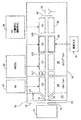
図1は、第1の実施例による質量分析装置10を示す。周知のように、装置10は、電気スプレイ、イオンスプレイ、コロナ放電デバイス、あるいはその他の周知のイオン源12を有している。イオン源12から供給されたイオンは、開口を設けたプレート16の開口14を通るように方向付けされる。前記プレート16の反対側には、供給源(図示せず)から送られるガスカーテンが供給されるカーテンガスチャンバ18が設けられている。前記カーテンガスは、適切なイオンスプレイデバイスを開示しているコーネルリサーチファンデーションに付与された米国特許No.4,861,988に記載されているように、アルゴン、窒素、その他の不活性ガスでよい。この特許の内容は、ここに引用することによって本文書中に取り込まれる。
FIG. 1 shows a
イオンは、オリフィスプレート20のオリフィス19を通って真空チャンバ21に差動排気される。イオンは更にスキマー(穴あき杓子)プレート24の開口22を通って第2の差動排気チャンバ26に入る。一般的に、差動排気チャンバ21の圧力は、1−2Torrほどであり、しばしば質量分析計の第1チャンバと考えられる第2の差動排気チャンバ26の圧力は、排気により約7−8mTorrとなっている。
The ions are differentially evacuated through the
前記チャンバ26では、従来の高周波オンリー多極イオンガイドQ0が設けられており、その機能は、イオンを冷却し、収束させるものであり、この機能は、チャンバ26内の比較的高いガス圧力によってアシストされる。このチャンバ26は、大気圧イオン源12と低圧力真空チャンバの間のインターフェースの働きをし、以後の処理に向かう前にイオン源からいっそう多くのガスを除去する働きをする。
The
インタカッドアパーチャIQ1は、第2のメーン真空チャンバ30からチャンバ26を分離する。第2のチャンバ30には、ブルベーカーレンズの役目をするST(軸方向長さが短いことを示すstubbies−切り株−の略)と名づけた高周波オンリーロッドがある。四重極ロッドセットQ1は、約1〜3×10⁻⁵Torrまで排気した真空チャンバに配置されている。第2の四重極ロッドセットQ2は、符号34で表示された衝突ガスが供給される衝突チャンバ内に配置されている。衝突セル32は、内容を本文書に引例として紹介した米国特許NO.6,111,250でトンプソンとジョリフェが教示する出口端寄りに伸びる軸方向電界を設けるように設計されている。セル32は、チャンバ30内にあり、両端にインタカッドアパーチャIQ2とIQ3を有しており、一般的にその内部圧力は5×10⁻⁴〜8×10⁻³Torr の範囲に、望ましくは約5×10⁻³Torrに保たれている。Q2の次には、35で示した第3の四重極ロッドセットQ3と、出口レンズ40が設けられている。Q3内の対向するロッドは、約8.5mmの間隔で隔てられることが望ましい。ただし、実際には、それ以外の間隔も検討されて、使用されている。Q3領域内の圧力は、通常Q1と同じ、即ち1〜3×10⁻⁵Torrである。検出器76が出口レンズ40を通って出てゆくイオンを検出するために設けられている。
RF用電源37、RF/DC用電源36、RF/DCおよび補助AC用電源38が設けられ、これらの電源は、四重極Q0,Q1,Q2,Q3に接続されている。Q0は、内容が本文書中に引例として紹介されている米国特許No.4,963,736が教示するように、イオンを冷却し収束させるRFオンリー多極イオンガイドQ0として作動する。Q1は、標準分解能型RE/DC四重極である。所定の前駆イオンだけあるいはある範囲のイオンだけをQ2に送るためRF/DC電圧が選択される。第1世代のフラグメントイオンを生成するため前駆イオンを解離するか、フラグメント化する目的でソース34から送られる衝突ガスがQ2に供給される。あるDC電圧がプレートIQ1,IQ2,IQ3および出口レンズ40に印加される(上述の電源のどれかを使うか、別の電源から供給する)。以下に詳しく説明するように、電源36、37および/または38の出力、および/または前記プレートに印加される電圧を、Q2前駆イオンがQ2に入る際に、前駆イオンの注入エネルギーを変えるために変化させてもよい。Q3は、軸方向イジェクション技術によって質量に依存する仕方でQ3においてイオンをトラップしスキャンアウトするために使用することができるリニアイオントラップとして作動させる。
An
例示した実施例において、イオン源12から供給されるイオンは、真空チャンバ30に導入される。真空チャンバでは、当業界では周知のように、必要に応じて、前駆イオンの質量電荷比(もしくは質量電荷比の範囲)を四重極ロッドセットに印加されるRF+DC電圧を操作することによりQ1を介して選択することができる。前駆イオンの選択に続いて、イオンは、望ましくは、Q1とIQ2との間における適切な電圧降下により加速されてQ2に送られ、米国特許No.5,248,875が教示するようにフラグメント化が誘起される。この内容はここに引用することにより取り込まれる。注入エネルギーに応じて、DC電圧がQ1とIQ2の間でおよそ0〜150V低下する。
In the illustrated embodiment, ions supplied from the
フラグメント化の程度は、部分的に衝突セルQ2およびQ1とIQ2との間の電圧差によって制御できる。好適実施例において、Q1とIQ2の間のDC電圧差は、前駆イオンに印加される注入エネルギーを変えるために変化させる。あるいは、Q1とQ2, IQ1とIQ2, IQ1とQ1, Q0とIQ1のそれぞれの間のDC電圧は、前駆イオンに印加された注入エネルギーを変えるために変化させる。同様に、テーパ状のロッドセットは、テーパの度合いに応じて注入エネルギーを変化させるために使用できる。イオン流が衝突セルに注入されるときにイオン流に印加される電圧を変化させるために他の手段を使うことも可能である。 The degree of fragmentation can be controlled in part by the collision cell Q2 and the voltage difference between Q1 and IQ2. In the preferred embodiment, the DC voltage difference between Q1 and IQ2 is varied to change the implantation energy applied to the precursor ions. Alternatively, the DC voltages between Q1 and Q2, IQ1 and IQ2, IQ1 and Q1, Q0 and IQ1, respectively, are varied to change the implantation energy applied to the precursor ions. Similarly, a tapered rod set can be used to vary the implantation energy depending on the degree of taper. Other means can be used to change the voltage applied to the ion stream as it is injected into the collision cell.
電圧は、予め定めた一定時間にわたり、予め選択したエネルギー範囲で離散ステップ状に上昇させることが望ましい。エネルギーは、一般的にエレクトロンボルト(eV)で表され、典型的な広がりは、50eVが可能である。ただし、20eVのような低い広がり、あるいは高い広がりを実際に使用してもよい。Q1とIQ2の間のDC電圧差は、望ましいエネルギー範囲を準備するように制御する方が好ましい。したがって、電圧の変化は、前駆イオンの質量と帯電状態に依存する。電圧の範囲を決め、IQ2にDC電位を印加する電源を制御するために、これらの計算を実行するソフトウェアプログラムを使用することが好ましい。電圧の範囲は、ステップ状に離散的に適用してもよい。例えば、CEを50eVの広がりとし、50msの注入時間において、電圧は、CEを10msごとに10eV増加するようにコントロールできる。あるいは、電圧を50msの間に50eVの範囲で連続的にコントロールできる。これに関して、直線状の、等比級数状の、放物線状の、あるいはその他の線図を使用してもよい。 It is desirable to increase the voltage in discrete steps over a predetermined energy range over a predetermined time period. Energy is generally expressed in electron volts (eV), and a typical spread can be 50 eV. However, a low spread such as 20 eV or a high spread may actually be used. The DC voltage difference between Q1 and IQ2 is preferably controlled to provide the desired energy range. Therefore, the change in voltage depends on the mass of the precursor ion and the charged state. It is preferable to use a software program that performs these calculations to determine the voltage range and control the power supply that applies a DC potential to IQ2. The voltage range may be applied discretely in steps. For example, CE can be spread by 50 eV, and at an injection time of 50 ms, the voltage can be controlled to increase CE by 10 eV every 10 ms. Alternatively, the voltage can be continuously controlled in the range of 50 eV for 50 ms. In this regard, linear, geometric series, parabolic or other diagrams may be used.
本好適実施例において、衝突エネルギーの広がりは、ユーザが入力する仕様とすることが好ましい。当業界で周知のことだが、ソフトウェアで最適衝突エネルギーを計算し、ユーザがその値の偏差を、例えば、あるパーセントだけブラスかマイナスして入力することが好ましい。 In the present preferred embodiment, the spread of the collision energy is preferably a specification input by the user. As is well known in the art, it is preferred that the software calculate the optimal collision energy and that the user enter the deviation of that value, for example, by a certain percentage brass or minus.
さらに、電圧を変化させる代わりに、前駆イオンに与えた運動量を、Q0とQ1の間でイオンが受ける圧力勾配を変えることにより変化させてもよい。あるいは、衝突エネルギーは、衝突セル32内の背景ガス圧力を変えることにより変化させてもよい。しかし、極めて短い時間に急速な圧力変化を設定し、コントロールするには実行上の問題があるのでこれらの方法は、現在のところ取らない方がよい。
Further, instead of changing the voltage, the momentum applied to the precursor ions may be changed by changing the pressure gradient applied to the ions between Q0 and Q1. Alternatively, the collision energy may be changed by changing the background gas pressure in the
運動量とQ2とQ3の間の周囲圧力勾配によって、非解離前駆イオンと共に第1世代のフラグメントイオンは、Q3に送り込まれる。内容が本文書に引例として紹介されたヘイガーが2000年7月21日に提出した同時出願中の米国特許出願09/864,878で教示しているように、前駆イオンおよび/または第1世代のフラグメントが更に解離が起きる。ただし、例示された実施例では、Q2は、ヘイガーの出願において教示しているようにトラップの働きをしていないことが理解される。しかし、必要なら、前駆イオンおよびフラグメントイオンがQ3に入り、更なる解離を最小限にする運動エネルギーをできるだけ抑制するように適切な圧力の低下あるいは利得がIQ3とQ3の間で確立できる。適切な充填時間のあとで、リニアイオントラップとして機能するQ3内の前駆イオンと第1世代フラグメントをトラップするためブロッキング電圧をIQ3に印加することができる。 Due to the momentum and the ambient pressure gradient between Q2 and Q3, the first generation fragment ions along with the undissociated precursor ions are pumped into Q3. As taught in co-pending US patent application 09 / 864,878 filed July 21, 2000 by Hager, the contents of which were incorporated by reference in this document, precursor ions and / or first generation Fragment further dissociates. However, in the illustrated example, it is understood that Q2 is not acting as a trap as taught in the Hager application. However, if necessary, a suitable pressure drop or gain can be established between IQ3 and Q3 so that the precursor and fragment ions enter Q3 and suppress as much kinetic energy as possible to minimize further dissociation. After an appropriate filling time, a blocking voltage can be applied to IQ3 to trap precursor ions and first generation fragments in Q3 that function as a linear ion trap.
一旦Q3にトラップされのち、質量電荷比(m/z)の特定値あるいは範囲を選択するため、前駆イオンおよび第1世代のフラグメントイオンを再度質量分離してもよい。必要なら、選択されたイオンをQ3の低圧力環境において共鳴励起させて第2世代のフラグメントイオン(すなわちフラグメントのフラグメント)を生成させてもよく、あるいは即時譲受人に譲渡される、内容が本文書中に引例として紹介されている同時出願中の特許出願60/370,205に詳細に記載されているように、選択された前駆イオンをフラグメント化してもよい。このあとイオンは、リニアイオントラップにおいて質量選択を通してスキャンアウトされ、Q3で第1世代フラグメントあるいは前駆イオンのどちらを解離するかによってMS3もしくはMS2スペクトルが得られる。トラップ、分離、フラグメント化のサイクルを一度以上行うことによりMSnスペクトル(n>3)が得られることが理解できる。 Once trapped in Q3, the precursor ion and the first generation fragment ions may be mass separated again to select a specific value or range of mass to charge ratio (m / z). If necessary, selected ions may be resonantly excited in the low pressure environment of Q3 to generate second generation fragment ions (ie, fragments of fragments), or transferred to an immediate assignee, the contents of this document Selected precursor ions may be fragmented as described in detail in co-pending patent application 60 / 370,205, which is incorporated herein by reference. The ions are then scanned out through mass selection in a linear ion trap and an MS 3 or MS 2 spectrum is obtained depending on whether Q3 dissociates the first generation fragment or the precursor ion. It can be seen that an MS n spectrum (n> 3) can be obtained by performing one or more cycles of trapping, separation, and fragmentation.
内容が本文書中に引例として紹介されている米国特許No.6,177,668で概ねのところが教示されている軸方向イジェクション技術をなるべくなら使用して、質量依存の方法でイオンをQ3においてスキャンアウトする。手短にいえば、米国特許No.6,177,668に開示される技術は、ロッドセットの、例えば、四重極ロッドセットの入り口にイオンを注入し、出口部にある障壁電界を設けることにより遠端でイオンをトラップすることを基にしている。RF電界を少なくとも障壁部に隣接するロッドに印加される。該RF電界は、ロッドセットの出口端と障壁部に隣接する取り出し領域において相互に作用して端部電界をつくりだす。取り出し領域にきたイオンは、電圧をかけられて、少なくとも選択された質量電荷比の若干のイオンが障壁電界を越えてロッドセットから軸方向に質量選択的にイジェクトされる。続いてイジェクトされたイオンが検出される。イオンを軸方向にイジェクトするさまざまな技術が教示されている。即ち、端部レンズと障壁に印加される補助AC電界を走査し、一定周波数の補助電圧を端部障壁に印加しながらロッドセットに印加されたRF電圧を走査し、前記レンズにかけたAC電圧および前記ロッドにかけたRF電圧のほかにロッドセットに補助AC電圧を印加するなどである。 If possible, use the axial ejection technique generally taught in US Pat. No. 6,177,668, the contents of which are introduced by reference in this document, and ion in Q3 in a mass dependent manner. Scan out. In short, the technique disclosed in U.S. Pat. No. 6,177,668 involves injecting ions into the entrance of a rod set, for example, a quadrupole rod set, and providing a barrier electric field at the exit. It is based on trapping ions at the far end. An RF electric field is applied to at least the rod adjacent to the barrier. The RF electric field interacts in the extraction area adjacent to the exit end of the rod set and the barrier to create an end electric field. Ions coming into the extraction region are energized and at least some ions with a selected mass-to-charge ratio are mass-selectively ejected axially from the rod set over the barrier field. Subsequently, the ejected ions are detected. Various techniques for axially ejecting ions are taught. That is, the auxiliary AC electric field applied to the end lens and the barrier is scanned, the RF voltage applied to the rod set is scanned while the auxiliary voltage having a constant frequency is applied to the end barrier, and the AC voltage applied to the lens and For example, an auxiliary AC voltage is applied to the rod set in addition to the RF voltage applied to the rod.
各リニアイオントラップは、厳密な幾何学的な構成に基づいた最適軸方向イジェクションのためには幾分か異なった頻度で行ってもよい。出口障壁、および各補助AC電圧を同時に増加すれば、同時出願中の特許出願60/370,205に詳細に記述されているようにイオンの軸方向イジェクションの効率を向上させる。 Each linear ion trap may be performed at a somewhat different frequency for optimal axial ejection based on a strict geometric configuration. Increasing the exit barrier and each auxiliary AC voltage simultaneously improves the efficiency of ion axial ejection as described in detail in co-pending patent application 60 / 370,205.
上述の装置による実験データのいくつかを図2と図3を参照しながら以下に説明する。 Some experimental data from the above-described apparatus will be described below with reference to FIGS.
図2は、グル−フェブリノペプチド(m/z=1570.6)のスキャン結果対CE(collision energy)値の対応に一定のCE値を使用した場合のフラグメント化パターン間の差を示す。CEの広がりをもとにしたアプローチには、2つの中心値が使用された。図2(a)のスペクトルは、CEのエネルギーの広がりを抑えてCEを30eVに固定した場合を示す。この他のスペクトルは、CEが20eVの広がりをもつ場合を示す。図2(b)のスペクトルでは、中心値を30eVとし、図2(c)のスペクトルの中心値を40eVとした場合を示す。図2(b)と図2(c)で明らかなように、CEを固定したスペクトルと比べて質量が小さいイオンも大きなイオンもともにより多く生成された。双方のケースで、有用な参考イオンや確認イオンとなるm/z=1570.6で残留前駆イオンが存在する。通常、40eV以上のCE値において、前駆イオンは完全にフラグメント化されるはずである。構造を明確にするうえに、このアプローチは、小さな分子のメタボリズム研究に使用できるし、さらにはフルスキャンモードの定量法研究にも使用できる可能性があろう。 FIG. 2 shows the difference between fragmentation patterns when a constant CE value is used for the correspondence of the scan result of the glu-febrinopeptide (m / z = 1570.6) versus the CE (collision energy) value. Two central values were used for the CE-based approach. The spectrum of FIG. 2A shows a case where CE is fixed at 30 eV while suppressing the spread of CE energy. This other spectrum shows the case where CE has a spread of 20 eV. In the spectrum of FIG. 2B, the center value is 30 eV, and the center value of the spectrum of FIG. 2C is 40 eV. As is clear from FIG. 2B and FIG. 2C, both ions having a smaller mass and larger ions were produced as compared with the spectrum in which CE was fixed. In both cases, residual precursor ions are present at m / z = 1570.6, which is a useful reference ion or confirmation ion. Usually, for CE values above 40 eV, the precursor ions should be completely fragmented. To clarify the structure, this approach could be used for small molecule metabolism studies and even for full-scan mode quantitative studies.
図3は、さまざまなCE値における固定CEスペクトルと比較するブロモクリプチン(m/z-654)のフラグメント化に応用したCEの広がりのスペクトルを示す。図3(a)は、15〜60eVの広がりを有するスペクトルをしめす。図3(b)、図3(c)、図3(d)は、それぞれ固定CE値が20eV,30eV,55eVのスペクトルである。固定CEが増加するにつれて、に対応して、小さな質量フラグメントが増加するにつれて、図3(d)の前駆イオン(m/z=654)のロスも増加する。図3(a)示すCEの広がりのスペクトルは、イオンフラグメントが増加し、前駆イオンが維持されるという利益がもたらされている。 FIG. 3 shows the spectrum of CE broadening applied to the fragmentation of bromocriptine (m / z-654) compared to a fixed CE spectrum at various CE values. FIG. 3 (a) shows a spectrum with a spread of 15-60 eV. FIGS. 3B, 3C, and 3D are spectra with fixed CE values of 20 eV, 30 eV, and 55 eV, respectively. As the fixed CE increases, the loss of the precursor ion (m / z = 654) in FIG. 3 (d) also increases as the small mass fragment increases. The spectrum of CE broadening shown in FIG. 3 (a) provides the benefit of increasing ion fragments and maintaining precursor ions.
CEの広がりをもとにしたアプローチは、イオンがフラグメント化されいずれの質量分析装置にも適用できることが了解されたであろう。例えば、Q3は、飛行時間(TOF)型デバイス、線形磁場型デバイス、四重極質量フィルタ、その他の質量スペクトル形成手段で代替できよう。 It will be appreciated that the CE-based approach can be applied to any mass spectrometer where ions are fragmented. For example, Q3 could be replaced by time-of-flight (TOF) devices, linear magnetic field devices, quadrupole mass filters, and other mass spectral shaping means.
上記中性ガス圧力や印加電圧は、いずれも例として示しただけであり、本発明の性能に影響を与えることなしに上記の開示された範囲や値以外で変化させてもよいことが理解できる。本文書に開示された実施例あるいは動作パラメータは、いずれも本発明の実施に対する絶対的な限度を示すものではなく、本出願人は、そのような動作パラメータを従来例で許されるほど広く主張することを意図している。当業者は、本発明の精神から逸脱することなしに本願に開示された実施例に対して、ほかの多くの変形や変更を行うことが可能であることを理解されるであろう。 It is understood that the above neutral gas pressure and applied voltage are only shown as examples, and may be changed outside the above disclosed ranges and values without affecting the performance of the present invention. . None of the embodiments or operating parameters disclosed in this document represent absolute limits on the practice of the present invention, and Applicants claim such operating parameters as widely as allowed in the prior art. Is intended. Those skilled in the art will appreciate that many other variations and modifications can be made to the embodiments disclosed herein without departing from the spirit of the invention.
Claims (25)
イオン流を生成するステップと、
前記イオン流を一定時間にわたって衝突セルに注入し、衝突誘起解離を促進させるステップと、
前記セルに注入を行っているあいだ前記イオン流が受ける衝突エネルギーを変化させるステップと、を含む方法。A method for fragmenting ions comprising:
Generating an ion stream;
Injecting the ion stream into the collision cell over a period of time to promote collision-induced dissociation;
Changing the collision energy experienced by the ion stream during implantation into the cell.
イオン流を生成する手段と、Means for generating an ion stream;
一定時間にわたって前記イオン流を衝突セルに注入し、前記イオンの衝突誘起解離を促進する手段と、Means for injecting the ion stream into the collision cell over a period of time to promote collision-induced dissociation of the ions;
前記セルへ注入している間、前記流れが受ける衝突エネルギーを変化させる手段と、を有するイオンフラグメント化装置。Means for changing the collision energy received by the flow during implantation into the cell.
線形構成として配置された第1と、第2の四重極ロッドセット、該第1のロッドセットは選択された前駆イオンを分離するように制御し、該第2のロッドセットは、前記第1のロッドセットの周囲よりもかなり高い背景ガス圧力となった衝突室に収容しており、と、First and second quadrupole rod sets arranged in a linear configuration, the first rod set is controlled to separate selected precursor ions, and the second rod set is Is housed in a collision chamber with a background gas pressure that is considerably higher than the surrounding of the rod set,
物質をイオン化し、イオン流を第1のロッドセットに注入するイオン化デバイスと、An ionization device for ionizing a substance and injecting an ion stream into a first rod set;
予め定めたエネルギー範囲にわたって前記イオンに与える衝突エネルギーを変化させるように、イオン流を衝突セルに注入する際に前記イオン流に加える電圧を変化させる手段と、Means for changing a voltage applied to the ion stream when the ion stream is injected into the collision cell so as to change a collision energy applied to the ions over a predetermined energy range;
前記第2のロッドセットから放射されるイオンの質量スペクトルを得るための質量フィルタと、を有する質量分析装置。And a mass filter for obtaining a mass spectrum of ions emitted from the second rod set.
線形構成として配置された第1、第2、第3の四重極ロッドセットであって、該第1の四重極ロッドセットは選択された前駆イオンを分離するように制御され、該第2の四重極ロッドセットは前記第1、第2のロッドセットの周囲よりもかなり高い背景ガス圧力となっている衝突室に収容し、該第3のロッドセットはリニアイオントラップとして制御される、第1、第2および第3の四重質量分析装置と、First, second, and third quadrupole rod sets arranged in a linear configuration, wherein the first quadrupole rod set is controlled to separate selected precursor ions, and the second The quadrupole rod set is housed in a collision chamber having a background gas pressure considerably higher than the surroundings of the first and second rod sets, and the third rod set is controlled as a linear ion trap. First, second and third quadruple mass spectrometers;
物質をイオン化し、イオン流を前記第1のロッドセットに注入するイオン化デバイスと、An ionization device for ionizing a substance and injecting an ion stream into the first rod set;
予め定めたエネルギー範囲にわたって前記イオンが受ける衝突エネルギーを変化させるように前記イオン流を衝突セルに注入する際に該イオン流に加える電圧を変化させる手段と、を有するトリプルステージ四重極質量分析装置。Means for changing a voltage applied to the ion flow when the ion flow is injected into the collision cell so as to change the collision energy received by the ions over a predetermined energy range. .
Applications Claiming Priority (2)
| Application Number | Priority Date | Filing Date | Title |
|---|---|---|---|
| US37635202P | 2002-04-29 | 2002-04-29 | |
| PCT/CA2003/000476 WO2003094197A1 (en) | 2002-04-29 | 2003-04-02 | Broad ion fragmentation coverage in mass spectrometry by varying the collision energy |
Publications (2)
| Publication Number | Publication Date |
|---|---|
| JP2005524211A JP2005524211A (en) | 2005-08-11 |
| JP4312708B2 true JP4312708B2 (en) | 2009-08-12 |
Family
ID=29401335
Family Applications (1)
| Application Number | Title | Priority Date | Filing Date |
|---|---|---|---|
| JP2004502324A Expired - Lifetime JP4312708B2 (en) | 2002-04-29 | 2003-04-02 | A method to obtain a wide ion fragmentation range in mass spectrometry by changing the collision energy |
Country Status (6)
| Country | Link |
|---|---|
| US (2) | US7351957B2 (en) |
| EP (1) | EP1502280B1 (en) |
| JP (1) | JP4312708B2 (en) |
| AU (1) | AU2003213945A1 (en) |
| CA (1) | CA2481777C (en) |
| WO (1) | WO2003094197A1 (en) |
Families Citing this family (37)
| Publication number | Priority date | Publication date | Assignee | Title |
|---|---|---|---|---|
| CA2481777C (en) | 2002-04-29 | 2012-08-07 | Mds Inc., Doing Business As Mds Sciex | Broad ion fragmentation coverage in mass spectrometry by varying the collision energy |
| US6800846B2 (en) | 2002-05-30 | 2004-10-05 | Micromass Uk Limited | Mass spectrometer |
| US6884995B2 (en) * | 2002-07-03 | 2005-04-26 | Micromass Uk Limited | Mass spectrometer |
| US8507285B2 (en) * | 2003-03-13 | 2013-08-13 | Agilent Technologies, Inc. | Methods and devices for identifying biopolymers using mass spectroscopy |
| GB0425426D0 (en) * | 2004-11-18 | 2004-12-22 | Micromass Ltd | Mass spectrometer |
| WO2006084363A1 (en) * | 2005-02-09 | 2006-08-17 | Thermo Finnigan Llc | Apparatus and method for an electro-acoustic ion transmittor |
| GB0511083D0 (en) * | 2005-05-31 | 2005-07-06 | Thermo Finnigan Llc | Multiple ion injection in mass spectrometry |
| WO2006128306A1 (en) * | 2005-06-03 | 2006-12-07 | Mds Inc. Doing Business Through Its Mds Sciex Divison | System and method for data collection in recursive mass analysis |
| JP4830450B2 (en) * | 2005-11-02 | 2011-12-07 | 株式会社島津製作所 | Mass spectrometer |
| EP1971998B1 (en) * | 2006-01-11 | 2019-05-08 | DH Technologies Development Pte. Ltd. | Fragmenting ions in mass spectrometry |
| JP4802032B2 (en) * | 2006-04-14 | 2011-10-26 | 日本電子株式会社 | Tandem mass spectrometer |
| GB0612503D0 (en) * | 2006-06-23 | 2006-08-02 | Micromass Ltd | Mass spectrometer |
| US7479629B2 (en) * | 2006-08-24 | 2009-01-20 | Agilent Technologies, Inc. | Multichannel rapid sampling of chromatographic peaks by tandem mass spectrometer |
| KR20090115930A (en) * | 2006-12-26 | 2009-11-10 | 브라이엄 영 유니버시티 | Serum proteomics system and associated methods |
| WO2008136040A1 (en) * | 2007-04-17 | 2008-11-13 | Shimadzu Corporation | Mass spectroscope |
| JP5308641B2 (en) * | 2007-08-09 | 2013-10-09 | アジレント・テクノロジーズ・インク | Plasma mass spectrometer |
| US7986484B2 (en) * | 2007-11-30 | 2011-07-26 | Hitachi Global Storage Technologies, Netherlands B.V. | Method and system for fabricating a data storage medium |
| WO2009114932A1 (en) | 2008-03-20 | 2009-09-24 | Mds Analytical Technologies, A Business Unit Of Mds Inc., | Systems and methods for analyzing substances using a mass spectrometer |
| EP2326931B1 (en) | 2008-09-19 | 2019-04-24 | MKS Instruments, Inc. | Ionization gauge with emission current and bias potential control |
| WO2010037216A1 (en) * | 2008-10-01 | 2010-04-08 | Mds Analytical Technologies, A Business Unit Of Mds Inc. | Method, system and apparatus for multiplexing ions in msn mass spectrometry analysis |
| CA2690487A1 (en) * | 2009-01-21 | 2010-07-21 | Schlumberger Canada Limited | Downhole mass spectrometry |
| FR2946147B1 (en) * | 2009-05-29 | 2012-08-31 | Biomerieux Sa | NOVEL METHOD FOR QUANTIFYING PROTEINS BY MASS SPECTROMETRY |
| WO2011091023A1 (en) * | 2010-01-20 | 2011-07-28 | Waters Technologies Corporation | Techniques for efficient fragmentation of peptides |
| JP5408107B2 (en) * | 2010-11-10 | 2014-02-05 | 株式会社島津製作所 | MS / MS mass spectrometer and program for the same |
| JP5543912B2 (en) * | 2010-12-27 | 2014-07-09 | 日本電子株式会社 | Mass spectrometer |
| EP2732458A4 (en) * | 2011-07-11 | 2015-05-20 | Dh Technologies Dev Pte Ltd | Method to control space charge in a mass spectrometer |
| GB201116065D0 (en) * | 2011-09-16 | 2011-11-02 | Micromass Ltd | Encoding of precursor ion beam to aid product ion assignment |
| US9347917B2 (en) * | 2012-03-28 | 2016-05-24 | Dh Technologies Development Pte. Ltd. | Mass spectrometry systems and methods for analyses on lipid and other ions using a unique workflow |
| WO2014096914A1 (en) * | 2012-12-20 | 2014-06-26 | Dh Technologies Development Pte. Ltd. | Scheduled ms3 for quantitation |
| US9293312B2 (en) * | 2013-03-15 | 2016-03-22 | Thermo Finnigan Llc | Identifying the occurrence and location of charging in the ion path of a mass spectrometer |
| US10068761B2 (en) | 2014-08-26 | 2018-09-04 | Micromass Uk Limited | Fast modulation with downstream homogenisation |
| GB201415045D0 (en) * | 2014-08-26 | 2014-10-08 | Micromass Ltd | Fast modulation with downstream homogenisation |
| EP3254298B1 (en) * | 2015-02-05 | 2023-10-18 | DH Technologies Development PTE. Ltd. | Rapid scanning of wide quadrupole rf windows while toggling fragmentation energy |
| CN109075012B (en) * | 2016-04-14 | 2021-01-26 | 英国质谱公司 | Two-dimensional MSMS |
| US10971344B2 (en) | 2018-09-07 | 2021-04-06 | Thermo Finnigan Llc | Optimized stepped collision energy scheme for tandem mass spectrometry |
| US20230118135A1 (en) * | 2020-03-24 | 2023-04-20 | Dh Technologies Development Pte. Ltd. | Three stage atmosphere to vacuum mass spectrometer inlet with additional declustering in the third stage |
| EP4174905A1 (en) * | 2021-10-29 | 2023-05-03 | Thermo Finnigan LLC | Methods for modifying mass spectral data acquisition in real time |
Family Cites Families (16)
| Publication number | Priority date | Publication date | Assignee | Title |
|---|---|---|---|---|
| US4234791A (en) * | 1978-11-13 | 1980-11-18 | Research Corporation | Tandem quadrupole mass spectrometer for selected ion fragmentation studies and low energy collision induced dissociator therefor |
| US4861988A (en) * | 1987-09-30 | 1989-08-29 | Cornell Research Foundation, Inc. | Ion spray apparatus and method |
| CA1307859C (en) * | 1988-12-12 | 1992-09-22 | Donald James Douglas | Mass spectrometer and method with improved ion transmission |
| US5248875A (en) * | 1992-04-24 | 1993-09-28 | Mds Health Group Limited | Method for increased resolution in tandem mass spectrometry |
| CA2229070C (en) * | 1995-08-11 | 2007-01-30 | Mds Health Group Limited | Spectrometer with axial field |
| US6177668B1 (en) * | 1996-06-06 | 2001-01-23 | Mds Inc. | Axial ejection in a multipole mass spectrometer |
| US6140638A (en) * | 1997-06-04 | 2000-10-31 | Mds Inc. | Bandpass reactive collision cell |
| US6015972A (en) * | 1998-01-12 | 2000-01-18 | Mds Inc. | Boundary activated dissociation in rod-type mass spectrometer |
| US6124591A (en) * | 1998-10-16 | 2000-09-26 | Finnigan Corporation | Method of ion fragmentation in a quadrupole ion trap |
| CA2255188C (en) | 1998-12-02 | 2008-11-18 | University Of British Columbia | Method and apparatus for multiple stages of mass spectrometry |
| US6586727B2 (en) * | 2000-06-09 | 2003-07-01 | Micromass Limited | Methods and apparatus for mass spectrometry |
| US6720554B2 (en) * | 2000-07-21 | 2004-04-13 | Mds Inc. | Triple quadrupole mass spectrometer with capability to perform multiple mass analysis steps |
| AU2002350343A1 (en) * | 2001-12-21 | 2003-07-15 | Mds Inc., Doing Business As Mds Sciex | Use of notched broadband waveforms in a linear ion trap |
| US7049580B2 (en) * | 2002-04-05 | 2006-05-23 | Mds Inc. | Fragmentation of ions by resonant excitation in a high order multipole field, low pressure ion trap |
| US20030189168A1 (en) * | 2002-04-05 | 2003-10-09 | Frank Londry | Fragmentation of ions by resonant excitation in a low pressure ion trap |
| CA2481777C (en) | 2002-04-29 | 2012-08-07 | Mds Inc., Doing Business As Mds Sciex | Broad ion fragmentation coverage in mass spectrometry by varying the collision energy |
-
2003
- 2003-04-02 CA CA2481777A patent/CA2481777C/en not_active Expired - Fee Related
- 2003-04-02 EP EP03709514.8A patent/EP1502280B1/en not_active Expired - Lifetime
- 2003-04-02 WO PCT/CA2003/000476 patent/WO2003094197A1/en active Application Filing
- 2003-04-02 JP JP2004502324A patent/JP4312708B2/en not_active Expired - Lifetime
- 2003-04-02 AU AU2003213945A patent/AU2003213945A1/en not_active Abandoned
- 2003-04-02 US US10/512,766 patent/US7351957B2/en not_active Expired - Lifetime
- 2003-04-28 US US10/425,190 patent/US7199361B2/en not_active Expired - Lifetime
Also Published As
| Publication number | Publication date |
|---|---|
| US7351957B2 (en) | 2008-04-01 |
| CA2481777A1 (en) | 2003-11-13 |
| CA2481777C (en) | 2012-08-07 |
| WO2003094197A1 (en) | 2003-11-13 |
| US7199361B2 (en) | 2007-04-03 |
| AU2003213945A1 (en) | 2003-11-17 |
| US20040041090A1 (en) | 2004-03-04 |
| US20050277789A1 (en) | 2005-12-15 |
| JP2005524211A (en) | 2005-08-11 |
| EP1502280A1 (en) | 2005-02-02 |
| EP1502280B1 (en) | 2013-09-04 |
Similar Documents
| Publication | Publication Date | Title |
|---|---|---|
| JP4312708B2 (en) | A method to obtain a wide ion fragmentation range in mass spectrometry by changing the collision energy | |
| US6815673B2 (en) | Use of notched broadband waveforms in a linear ion trap | |
| CA2636821C (en) | Concentrating mass spectrometer ion guide, spectrometer and method | |
| US7943902B2 (en) | Method for introducing ions into an ion trap and an ion storage apparatus | |
| US7820961B2 (en) | Mass spectrometer and method of mass spectrometry | |
| US6967323B2 (en) | Mass spectrometer | |
| US7692143B2 (en) | Method for axial ejection and in-trap fragmentation using auxiliary electrodes in a multipole mass spectrometer | |
| WO2015133259A1 (en) | Ion analyzer | |
| JP4463978B2 (en) | Method and apparatus for selective collision-induced dissociation of ions in a quadrupole ion guide | |
| JP2004504622A (en) | Triple quadrupole mass spectrometer with multi-stage mass spectrometry capability | |
| WO2007052372A1 (en) | Mass-spectrometer and method for mass-spectrometry | |
| GB2414342A (en) | Tandem mass spectrometry method | |
| EP2113129A2 (en) | Mass spectrometer | |
| US20140353491A1 (en) | Creating an ion-ion reaction region within a low-pressure linear ion trap | |
| WO2003088306A1 (en) | Fragmentation of ions by resonant excitation in a low pressure ion trap | |
| US11031232B1 (en) | Injection of ions into an ion storage device | |
| JP2022500812A (en) | RF ion trap ion loading method | |
| JP2009146913A (en) | Mass spectrometer |
Legal Events
| Date | Code | Title | Description |
|---|---|---|---|
| A621 | Written request for application examination |
Free format text: JAPANESE INTERMEDIATE CODE: A621 Effective date: 20060310 |
|
| A131 | Notification of reasons for refusal |
Free format text: JAPANESE INTERMEDIATE CODE: A131 Effective date: 20081010 |
|
| A601 | Written request for extension of time |
Free format text: JAPANESE INTERMEDIATE CODE: A601 Effective date: 20090108 |
|
| A602 | Written permission of extension of time |
Free format text: JAPANESE INTERMEDIATE CODE: A602 Effective date: 20090202 |
|
| A601 | Written request for extension of time |
Free format text: JAPANESE INTERMEDIATE CODE: A601 Effective date: 20090210 |
|
| A602 | Written permission of extension of time |
Free format text: JAPANESE INTERMEDIATE CODE: A602 Effective date: 20090303 |
|
| A521 | Request for written amendment filed |
Free format text: JAPANESE INTERMEDIATE CODE: A523 Effective date: 20090309 |
|
| TRDD | Decision of grant or rejection written | ||
| A01 | Written decision to grant a patent or to grant a registration (utility model) |
Free format text: JAPANESE INTERMEDIATE CODE: A01 Effective date: 20090417 |
|
| A01 | Written decision to grant a patent or to grant a registration (utility model) |
Free format text: JAPANESE INTERMEDIATE CODE: A01 |
|
| A61 | First payment of annual fees (during grant procedure) |
Free format text: JAPANESE INTERMEDIATE CODE: A61 Effective date: 20090513 |
|
| FPAY | Renewal fee payment (event date is renewal date of database) |
Free format text: PAYMENT UNTIL: 20120522 Year of fee payment: 3 |
|
| R150 | Certificate of patent or registration of utility model |
Free format text: JAPANESE INTERMEDIATE CODE: R150 Ref document number: 4312708 Country of ref document: JP Free format text: JAPANESE INTERMEDIATE CODE: R150 |
|
| FPAY | Renewal fee payment (event date is renewal date of database) |
Free format text: PAYMENT UNTIL: 20130522 Year of fee payment: 4 |
|
| R250 | Receipt of annual fees |
Free format text: JAPANESE INTERMEDIATE CODE: R250 |
|
| R250 | Receipt of annual fees |
Free format text: JAPANESE INTERMEDIATE CODE: R250 |
|
| R250 | Receipt of annual fees |
Free format text: JAPANESE INTERMEDIATE CODE: R250 |
|
| R250 | Receipt of annual fees |
Free format text: JAPANESE INTERMEDIATE CODE: R250 |
|
| R250 | Receipt of annual fees |
Free format text: JAPANESE INTERMEDIATE CODE: R250 |
|
| R250 | Receipt of annual fees |
Free format text: JAPANESE INTERMEDIATE CODE: R250 |
|
| R250 | Receipt of annual fees |
Free format text: JAPANESE INTERMEDIATE CODE: R250 |
|
| R250 | Receipt of annual fees |
Free format text: JAPANESE INTERMEDIATE CODE: R250 |
|
| R250 | Receipt of annual fees |
Free format text: JAPANESE INTERMEDIATE CODE: R250 |
|
| R250 | Receipt of annual fees |
Free format text: JAPANESE INTERMEDIATE CODE: R250 |
|
| R250 | Receipt of annual fees |
Free format text: JAPANESE INTERMEDIATE CODE: R250 |
|
| EXPY | Cancellation because of completion of term |