JP4312140B2 - Method for producing breathable sheet and method for producing absorbent article - Google Patents
Method for producing breathable sheet and method for producing absorbent article Download PDFInfo
- Publication number
- JP4312140B2 JP4312140B2 JP2004290697A JP2004290697A JP4312140B2 JP 4312140 B2 JP4312140 B2 JP 4312140B2 JP 2004290697 A JP2004290697 A JP 2004290697A JP 2004290697 A JP2004290697 A JP 2004290697A JP 4312140 B2 JP4312140 B2 JP 4312140B2
- Authority
- JP
- Japan
- Prior art keywords
- sheet
- hot melt
- ink
- printing
- melt adhesive
- Prior art date
- Legal status (The legal status is an assumption and is not a legal conclusion. Google has not performed a legal analysis and makes no representation as to the accuracy of the status listed.)
- Expired - Fee Related
Links
Images


Classifications
-
- B—PERFORMING OPERATIONS; TRANSPORTING
- B41—PRINTING; LINING MACHINES; TYPEWRITERS; STAMPS
- B41J—TYPEWRITERS; SELECTIVE PRINTING MECHANISMS, i.e. MECHANISMS PRINTING OTHERWISE THAN FROM A FORME; CORRECTION OF TYPOGRAPHICAL ERRORS
- B41J3/00—Typewriters or selective printing or marking mechanisms characterised by the purpose for which they are constructed
- B41J3/407—Typewriters or selective printing or marking mechanisms characterised by the purpose for which they are constructed for marking on special material
- B41J3/4078—Printing on textile
-
- A—HUMAN NECESSITIES
- A61—MEDICAL OR VETERINARY SCIENCE; HYGIENE
- A61F—FILTERS IMPLANTABLE INTO BLOOD VESSELS; PROSTHESES; DEVICES PROVIDING PATENCY TO, OR PREVENTING COLLAPSING OF, TUBULAR STRUCTURES OF THE BODY, e.g. STENTS; ORTHOPAEDIC, NURSING OR CONTRACEPTIVE DEVICES; FOMENTATION; TREATMENT OR PROTECTION OF EYES OR EARS; BANDAGES, DRESSINGS OR ABSORBENT PADS; FIRST-AID KITS
- A61F13/00—Bandages or dressings; Absorbent pads
- A61F13/15—Absorbent pads, e.g. sanitary towels, swabs or tampons for external or internal application to the body; Supporting or fastening means therefor; Tampon applicators
- A61F13/51—Absorbent pads, e.g. sanitary towels, swabs or tampons for external or internal application to the body; Supporting or fastening means therefor; Tampon applicators characterised by the outer layers
- A61F13/514—Backsheet, i.e. the impermeable cover or layer furthest from the skin
-
- B—PERFORMING OPERATIONS; TRANSPORTING
- B41—PRINTING; LINING MACHINES; TYPEWRITERS; STAMPS
- B41J—TYPEWRITERS; SELECTIVE PRINTING MECHANISMS, i.e. MECHANISMS PRINTING OTHERWISE THAN FROM A FORME; CORRECTION OF TYPOGRAPHICAL ERRORS
- B41J2/00—Typewriters or selective printing mechanisms characterised by the printing or marking process for which they are designed
- B41J2/005—Typewriters or selective printing mechanisms characterised by the printing or marking process for which they are designed characterised by bringing liquid or particles selectively into contact with a printing material
- B41J2/01—Ink jet
- B41J2/17—Ink jet characterised by ink handling
- B41J2/175—Ink supply systems ; Circuit parts therefor
- B41J2/17593—Supplying ink in a solid state
Description
本発明は、各種印刷模様が施された通気性シートの製造方法、及び該通気性シートを用いた吸収性物品の製造方法に関する。 The present invention relates to a method for producing a breathable sheet on which various printed patterns have been applied, and a method for producing an absorbent article using the breathable sheet.
不織布、合成紙、織物などのような繊維を多量に含むシート状物(繊維状シート)は、通気性を必要とする製品をはじめ、様々な製品の原材料として使用されており、各種模様や製造業者のブランドマークなどの印刷模様を施した製品を製造する場合、その印刷媒体とされることも少なくない。例えば、使い捨ておむつや生理用ナプキン等の吸収性物品では、吸収性材料に対して非肌当接面側に位置する外装体(裏面シート)をはじめ、多くの部材に不織布が使用されているが、このような吸収性物品の印刷模様は、これまではバックシートなどのフィルム上に印刷されることも多かったが、最近では、外装体や個装用などの不織布部分に施されることもある。この場合の印刷手段としては、従来、グラビア印刷法やフレキソ印刷法などが利用されていたが、最近では、これらの印刷法に代わってインクジェット印刷法が利用されるようになってきている(例えば、特許文献1及び2参照)。インクジェット印刷法は、インクジェットヘッドの微小なノズルからインク滴を吐出させ、これを印刷媒体に付着させることにより印刷模様を形成する印刷法であり、印刷版を必要とせず、比較的簡易な設備でありながら高速印刷が可能であるため、吸収性物品の製造工程に組み込まれた場合には、印刷パターンの異なる多種多様な吸収性物品を効率良く製造することが可能となる。 Sheets (fibrous sheets) containing a large amount of fibers such as non-woven fabrics, synthetic papers and woven fabrics (fibrous sheets) are used as raw materials for various products, including products that require air permeability. When a product with a printed pattern such as a brand mark of a supplier is manufactured, it is often used as the print medium. For example, in absorbent articles such as disposable diapers and sanitary napkins, nonwoven fabrics are used for many members including exterior bodies (back sheet) positioned on the non-skin contact surface side with respect to the absorbent material. In addition, the printed pattern of such an absorbent article has been often printed on a film such as a back sheet, but recently, it may be applied to a non-woven fabric portion such as an exterior body or individual use. . Conventionally, gravure printing, flexographic printing, and the like have been used as printing means in this case, but recently, inkjet printing has been used in place of these printing methods (for example, Patent Documents 1 and 2). The ink jet printing method is a printing method in which ink droplets are ejected from minute nozzles of an ink jet head and adhered to a printing medium to form a printed pattern, which does not require a printing plate and is a relatively simple facility. Since high-speed printing is possible, it is possible to efficiently manufacture a wide variety of absorbent articles having different printing patterns when incorporated in the manufacturing process of the absorbent article.
また、インクジェット印刷法に適したシート状物なども提案されている。例えば、印刷模様の滲みが少なく、印刷後に洗濯しても印刷模様が色褪せないインクジェット印刷可能材料として、セルロース不織布と、天然又は合成ポリマーから形成された不織布を含む層とを接着剤により接着させたものが知られている(特許文献3参照)。
不織布などの繊維状シートに対してインクジェット印刷を行った場合、インク滴が繊維状シートを通り抜けてしまう、いわゆる裏抜けが発生することがあり、製品の製造ラインにおけるガイドロール汚れやガイドロールからの汚れが転写して製品自体をインクで汚すという問題があった。近年は不織布が薄層化してきており、裏抜けしやすい傾向にある。特に、高速インクジェット印刷の場合は、解像度が高いためインク滴が小さく、また、インク滴の吐出速度が大きくなるため、インク滴が繊維状シートを通り抜けやすく、裏抜けの発生率が高い。従って、印刷速度の一層の高速化を目指す観点からも、裏抜けは早急な解決が望まれる問題である。また、裏抜けが発生すると、本来印刷模様の形成に使用されるべきインクの一部が、印刷模様の形成に寄与しないことになるため、印刷濃度が不充分となり、鮮明な印刷模様が得られない場合がある。また、繊維状シート上にインクジェット印刷により形成された印刷模様は、堅牢性に問題があり、わずかな摩擦や水に濡れただけで色材が剥がれ落ちることがある。 When inkjet printing is performed on a fibrous sheet such as a non-woven fabric, ink drops may pass through the fibrous sheet, so-called back-through may occur. There was a problem that the dirt was transferred and the product itself was stained with ink. In recent years, nonwoven fabrics have become thinner and tend to break through. In particular, in the case of high-speed ink jet printing, the ink droplets are small because the resolution is high, and the discharge speed of the ink droplets is large. Accordingly, from the viewpoint of further increasing the printing speed, the show-through is a problem for which an immediate solution is desired. In addition, when the strike-through occurs, a part of the ink that should originally be used for forming the print pattern does not contribute to the formation of the print pattern, so that the print density becomes insufficient and a clear print pattern is obtained. There may not be. Moreover, the printed pattern formed on the fibrous sheet by ink jet printing has a problem of fastness, and the coloring material may be peeled off only by being slightly rubbed or wetted by water.
従って、本発明の目的は、裏抜けを発生させず、堅牢性に優れた印刷模様が施された通気性シートの製造が可能な通気性シートの製造方法、及び該通気性シートを用いた吸収性物品の製造方法を提供することにある。 Therefore, an object of the present invention is to produce a breathable sheet capable of producing a breathable sheet with a printed pattern having excellent fastness without causing back-through, and an absorption using the breathable sheet. It is in providing the manufacturing method of a property article.
本発明は、印刷模様が施された通気性シートの製造方法であって、繊維状シートの一方の面にホットメルト接着剤を塗布した後、該ホットメルト接着剤の塗布部分に又は該繊維状シートの他方の面における該塗布部分と対向する部分に、前記印刷模様をインクジェット印刷により施すことを特徴とする通気性シートの製造方法を提供することにより、前記目的を達成したものである。 The present invention relates to a method for producing a breathable sheet having a printed pattern, wherein a hot melt adhesive is applied to one surface of a fibrous sheet and then applied to the application portion of the hot melt adhesive or the fibrous sheet. The object is achieved by providing a method for producing a breathable sheet, characterized in that the printed pattern is applied to a portion of the other surface of the sheet facing the coated portion by ink jet printing.
また、本発明は、吸収性本体と、該吸収性本体の非肌当接面側に位置する外装体とを具備する吸収性物品の製造方法であって、繊維状シートの一方の面にホットメルト接着剤を塗布した後、該ホットメルト接着剤の塗布部分に又は該繊維状シートの他方の面における該塗布部分と対向する部分に、前記印刷模様をインクジェット印刷により施す工程と、前記印刷模様を施された前記繊維状シートを、施された該印刷模様が外部に露出しないように前記吸収性本体に前記外装体として配置する工程とを有する吸収性物品の製造方法を提供することにより、前記目的を達成したものである。 The present invention also relates to a method for manufacturing an absorbent article comprising an absorbent main body and an exterior body positioned on the non-skin-contacting surface side of the absorbent main body, wherein one surface of the fibrous sheet is hot. A step of applying the printed pattern by inkjet printing to the application part of the hot melt adhesive or a part of the other side of the fibrous sheet facing the application part after applying the melt adhesive; and By providing the fibrous sheet subjected to the above, the method of manufacturing an absorbent article having a step of arranging the fibrous sheet as the exterior body on the absorbent main body so that the applied printed pattern is not exposed to the outside, The object has been achieved.
本発明の通気性シートの製造方法によれば、不織布等の繊維状シートにホットメルト接着剤を塗布した後で、その塗布部分に、あるいは該繊維状シートを介して略反対側に位置する部分(繊維状シートの他方の面における該塗布部分と対向する部分)に、インクジェット印刷により印刷模様を施すようにすることにより、インクジェットヘッドから吐出されたインク滴をホットメルト接着剤で受けるようにしたので、インクの裏抜けが効果的に防止され、製品の製造ラインや製品自体のインク汚れ、印刷速度の低下、画像濃度の低下といった裏抜けに起因する種々の弊害を未然に防止することができる。また、ホットメルト接着剤によりインクの定着性が高まるため、印刷模様の堅牢性が向上し、色落ちしにくい通気性シートが得られる。 According to the method for producing a breathable sheet of the present invention, after a hot melt adhesive is applied to a fibrous sheet such as a non-woven fabric, a portion located on the coated portion or on the substantially opposite side through the fibrous sheet By applying a print pattern by ink jet printing on the other side of the fibrous sheet facing the coated part, ink droplets ejected from the ink jet head are received by a hot melt adhesive. As a result, ink breakthrough can be effectively prevented, and various problems caused by breakthrough such as ink stains on the product production line and the product itself, a reduction in printing speed, and a reduction in image density can be prevented. . In addition, since the fixability of the ink is enhanced by the hot melt adhesive, the fastness of the printed pattern is improved, and a breathable sheet that does not easily lose color can be obtained.
また、本発明の吸収性物品の製造方法によれば、印刷模様が施される部材(外装体)を、前記の通気性シートの製造方法に準じた方法により製造するようにしたので、印刷模様の視認性及び堅牢性に優れた吸収性物品が得られる。また、インクが肌に密着して剥離するのを防ぐ観点から、吸収性物品の外装体の外側表面や内側表面のうち、肌に接触する可能性のある部分にはインクを付着させないことが好ましいが、本発明では、前記のように、インクの裏抜けが効果的に防止されるため、肌当接面に不要なインクが付着するおそれがなく、良好な吸収性物品が得られる。 Moreover, according to the manufacturing method of the absorbent article of the present invention, the member (exterior body) to which the printing pattern is applied is manufactured by a method according to the manufacturing method of the breathable sheet. An absorbent article excellent in visibility and fastness can be obtained. Further, from the viewpoint of preventing the ink from coming into close contact with the skin, it is preferable not to allow the ink to adhere to a portion of the outer surface or inner surface of the absorbent article that may come into contact with the skin. However, in the present invention, as described above, since the ink can be effectively prevented from passing through, unnecessary ink may not adhere to the skin contact surface, and a good absorbent article can be obtained.
以下、先ず、本発明の通気性シートの製造方法について、その好ましい一実施形態に基づき図面を参照しながら説明する。
本発明の製造目的物である通気性シートは、繊維状シートに印刷模様が施されたものである。図1は、本発明の通気性シートの製造方法の一実施形態の工程概略説明図である。本実施形態においては、先ず、ロール状に巻かれた繊維状シート1を繰り出し、該繊維状シート1の一方の面にホットメルト接着剤を塗布する。これにより、該繊維状シート1の一方の面に接着剤層(塗布部分)3が形成される。ホットメルト接着剤の塗布は、接着剤塗布装置2を用いて行われる。
Hereinafter, first, the manufacturing method of the air permeable sheet of this invention is demonstrated, referring drawings based on the preferable one Embodiment.
The breathable sheet, which is the production object of the present invention, is a fibrous sheet with a printed pattern. FIG. 1 is a process schematic explanatory diagram of an embodiment of a method for producing a breathable sheet of the present invention. In this embodiment, first, the fibrous sheet 1 wound in a roll shape is fed out, and a hot melt adhesive is applied to one surface of the fibrous sheet 1. Thereby, an adhesive layer (application portion) 3 is formed on one surface of the fibrous sheet 1. Application | coating of a hot-melt-adhesive is performed using the adhesive
上記繊維状シートとしては、セルロースなどの天然繊維及び/又はポリエチレン、ポリプロピレン、ポリエステルなどの熱可塑性樹脂を原料とした合成繊維を主成分とする(該シートの乾燥重量の50重量%以上が繊維である)シート状物が挙げられ、吸水性の繊維のみならず、非吸水性の繊維から構成されるシートも使用できる。該繊維状シートには、粉砕パルプや無機又は有機の顔料成分等を含ませることができる。本発明では、繊維状シートとして、具体例としては不織布を使用することができ、その他、合成紙や織物などを使用することもできる。また、一般に、カード式の不織布には繊維油剤が使用されており、インクの定着性に乏しい面があるが、本発明の製造方法によれば、このような繊維シート(カード式の不織布)に対しても堅牢性の高い印刷模様を施すことができる。また、本発明では、坪量の少ない(厚みの薄い)繊維状シートを使用しても、インクの裏抜けが発生しないため、坪量30g/m2以下の繊維状シートを使用することができる。特に、通気性や柔軟性の観点から、坪量22g/m2以下、特に坪量16g/m2以下の繊維状シートが好ましい。尚、強度の観点から、繊維状シートの坪量は4g/m2以上必要である。 The fibrous sheet is mainly composed of natural fibers such as cellulose and / or synthetic fibers made from thermoplastic resins such as polyethylene, polypropylene, polyester, etc. (50% by weight or more of the dry weight of the sheet is fibers. A sheet), and not only water-absorbing fibers but also sheets composed of non-water-absorbing fibers can be used. The fibrous sheet can contain pulverized pulp, inorganic or organic pigment components, and the like. In the present invention, as the fibrous sheet, a non-woven fabric can be used as a specific example, and synthetic paper or woven fabric can also be used. In general, a fiber oil agent is used for a card-type nonwoven fabric, and there is a surface with poor ink fixability, but according to the production method of the present invention, such a fiber sheet (card-type nonwoven fabric) is used. In contrast, a printed pattern having high robustness can be applied. Further, in the present invention, even if a fibrous sheet having a small basis weight (thin thickness) is used, no ink breakthrough occurs, so a fibrous sheet having a basis weight of 30 g / m 2 or less can be used. . In particular, a fibrous sheet having a basis weight of 22 g / m 2 or less, particularly a basis weight of 16 g / m 2 or less is preferable from the viewpoint of air permeability and flexibility. From the viewpoint of strength, the basis weight of the fibrous sheet needs to be 4 g / m 2 or more.
上記ホットメルト接着剤としては、例えば、SIS(スチレン−イソプレン−スチレンブロックポリマー)、SIBS(スチレン−イソプレン−ブタジエン−スチレンブロックコポリマー)、SEBS(スチレン−エチレン−ブチレン−スチレンブロックポリマー)、SEPS(スチレン−エチレン−プロピレン−スチレンブロックポリマー)等のスチレン系エラストマー;エチレン・酢酸ビニル系コポリマー;ポリエステル系、アクリル系、ポリオレフィン系等のエラストマー類;ポリイソブチレン、ブチルゴム、ポリイソプレン、天然ゴム等のゴム類等が好ましく用いられる。これらの中でも、特に、スチレン系エラストマーは、繊維状になり易く均一に塗布できるため、本発明で好ましく用いられる。また、ホットメルト接着剤の塗布方式は特に限定されず、コーター方式、スパイラル方式(オメガ方式、デュラウエーブ方式等)、スプレー方式、カーテンスプレー方式など公知のものを利用することができる。 Examples of the hot melt adhesive include SIS (styrene-isoprene-styrene block polymer), SIBS (styrene-isoprene-butadiene-styrene block copolymer), SEBS (styrene-ethylene-butylene-styrene block polymer), and SEPS (styrene). -Styrene elastomers such as ethylene-propylene-styrene block polymers); ethylene / vinyl acetate copolymers; polyesters, acrylics, polyolefins, etc .; rubbers such as polyisobutylene, butyl rubber, polyisoprene, natural rubber, etc. Is preferably used. Among these, styrene-based elastomers are particularly preferably used in the present invention because they easily become fibrous and can be applied uniformly. Further, the application method of the hot melt adhesive is not particularly limited, and a known method such as a coater method, a spiral method (such as an omega method or a duraave method), a spray method, or a curtain spray method can be used.
また、接着剤層3(ホットメルト接着剤の塗布部分)は、多数本の繊維状ホットメルト接着剤がランダムに付着し合って形成された網状体であることが好ましい。接着剤層3が、このような網状体(繊維状ホットメルト接着剤の集合体)から形成されることで、接着剤塗布により懸念される通気性の低下を回避することが可能となる。繊維状ホットメルト接着剤の繊維径は、インク滴の吐出による衝撃に堪えうる強度を有し、ある程度緻密な網状体を形成する観点から、0.5〜30μmが好ましい。また、この網状体における繊維状ホットメルト接着剤同士の平均繊維間距離は、インク滴を確実にトラップする観点から、5μm以下が好ましい。該平均繊維間距離は、電子顕微鏡写真を使って求めることができ、1本の線上に交差する繊維数で測定長さを除した値から、繊維径を減ずることにより算出される。
Moreover, it is preferable that the adhesive layer 3 (applied portion of the hot melt adhesive) is a network formed by attaching a large number of fibrous hot melt adhesives at random. By forming the
上記網状体は、カーテンスプレー方式を利用することで形成することができる。カーテンスプレー方式を利用した接着剤塗布装置(カーテンスプレーコーター)は、通常、複数の小さな吐出孔群が直線状に配列され、各吐出孔近傍に加熱空気を高速で噴出することのできるエアー噴出口を備えており、このカーテンスプレーコーターによれば、吐出孔から線状に吐出された溶融状態のホットメルト接着剤に対し、加熱空気が高速で吹き付けられることによって、ホットメルト接着剤が細長く引き延ばされた後、破断して、短く細い繊度の繊維状物となる。多数の吐出孔群から吐出されたホットメルト接着剤がこのような短い繊維状物となって、走行している繊維状シート1上へと落下していくので、多数本の繊維状ホットメルト接着剤がランダムに付着し合った網状体が、繊維状シート1上に形成され、接着剤層3が形成されることとなる。
The mesh body can be formed by using a curtain spray method. An adhesive application device (curtain spray coater) that uses a curtain spray system is usually an air outlet that has a plurality of small discharge hole groups arranged in a straight line, and can discharge heated air in the vicinity of each discharge hole at high speed. According to this curtain spray coater, the hot melt adhesive is elongated in an elongated manner by spraying heated air at a high speed against the molten hot melt adhesive discharged linearly from the discharge holes. After being stretched, it breaks into a short and fine fibrous material. Since the hot melt adhesive discharged from a large number of discharge hole groups becomes such a short fibrous material and drops onto the traveling fibrous sheet 1, a large number of fibrous hot melt adhesives are used. A net-like body in which the agent adheres at random is formed on the fibrous sheet 1, and the
また、接着剤層3(ホットメルト接着剤の塗布部分)の別の好ましい形態としては、ホットメルト接着剤の被膜の表面に、部分的に微細な孔が形成されている多孔性の膜状体が挙げられる。該膜状体は、コーター方式によりホットメルト接着剤を塗布することで形成することができる。該膜状体は、その開孔部分により通気性を有していると共に、孔の形成されていない部分でインク滴をトラップすることができ、インクの定着性にも優れるため好ましい。 Further, as another preferred form of the adhesive layer 3 (application portion of the hot melt adhesive), a porous film-like body in which fine pores are partially formed on the surface of the hot melt adhesive film Is mentioned. The film-like body can be formed by applying a hot melt adhesive by a coater method. The film-like body is preferable because it has air permeability due to the opening portion and can trap ink droplets in the portion where no hole is formed, and is excellent in ink fixing property.
上記ホットメルト接着剤の塗布量は、インクジェット印刷時に懸念されるインクの裏抜けを効果的に防止する、インクの定着性を高める、均一な接着剤層を形成する、シート同士の接着強度を確保する等の観点から、固形分換算で0.5g/m2以上とすることが好ましいが、接着剤を必要以上に塗布するとシートの通気性が著しく低下して好ましくないので、0.8〜7g/m2とすることがさらに好ましい。より好ましい接着剤の塗布量は1.5〜5g/m2であり、該塗布量が該範囲内であると、シートの充分な柔軟性が確保できる。尚、最終的に得られる通気性シートのJIS L1096のフラジール形法又はガーレ形法によって規定する通気度は、0.002s/ml以上であることが好ましく、さらには0.005〜0.07s/mlであると、インクの裏抜け防止と優れた通気性とが両立できるので好ましい。 The amount of hot melt adhesive applied effectively prevents ink back-through, which is a concern during ink-jet printing, enhances ink fixability, forms a uniform adhesive layer, and ensures adhesive strength between sheets. From the standpoint of, for example, it is preferable to be 0.5 g / m 2 or more in terms of solid content, but if the adhesive is applied more than necessary, the air permeability of the sheet is remarkably lowered, so 0.8 to 7 g. / M 2 is more preferable. A more preferable application amount of the adhesive is 1.5 to 5 g / m 2 , and when the application amount is within the range, sufficient flexibility of the sheet can be secured. The air permeability defined by the JIS L1096 Frazier method or Gurley method of the finally obtained breathable sheet is preferably 0.002 s / ml or more, more preferably 0.005 to 0.07 s / ml. In the case of ml, it is preferable because both prevention of ink back-through and excellent air permeability can be achieved.
次いで、接着剤層3(ホットメルト接着剤の塗布部分)に、所望の印刷模様をインクジェット印刷により施す。即ち、印刷台4上に搬送されてきた接着剤層3に対し、ホストコンピュータ(図示せず)から送られてきた印刷画像データに基づいて、インクジェットヘッド5を繊維状シート1の搬送方向(副走査方向)と直交する方向(主走査方向)にシリアルスキャンさせつつ、そのノズルから各色インクのインク滴を吐出させて、該接着剤層3上に所定パターンでインク6を付着させる。尚、接着剤層上に実際に付着するのは、インク中に含まれる色材等の固形分である。また、インクジェット印刷は、微小なインク滴を吐出させる非接触型印刷方式であるため、仮に、印刷画像データとしては接着剤層3の表面に対してデューティー100%でインクを付与(いわゆるベタ印刷)することになっていたとしても、実際に該表面の全面がインク(色材)で覆われることはなく、接着剤層3の接着力がインクジェット印刷によって完全に阻害されることはない。従って、印刷模様が施された接着剤層3の接着力のみで、後述するように、その通気性シートと別のシート状物とを貼り合わせることも可能である。
Next, a desired printing pattern is applied to the adhesive layer 3 (application portion of the hot melt adhesive) by ink jet printing. That is, the
インクジェットヘッドのインク吐出方式には、キャノン社製のバブルジェット(登録商標)方式に代表される、ヒータなどの電気−熱変換素子を利用した電気−熱変換方式の他、ピエゾ素子などの圧電素子を利用した電気−機械変換方式や、電極などの静電気力発生手段を利用したものなどがあるが、本発明ではいずれの方式でも利用できる。また、インクジェット印刷用インクとしては、通常のインクジェット印刷で用いられるインクであればよい。一般的なインクジェット印刷用インクは、染料系あるいは顔料系の色材を用い、溶媒として水、アルコールを用い、さらに必要に応じて湿潤剤、浸透剤などが添加されている。カラー印刷を行う場合は、イエロー、マゼンタ及びシアンの減法混色の3原色のインク、あるいはこれらにブラックその他の色のインクを加えた4色以上のインクを用いる。 Ink jet methods for inkjet heads include piezoelectric devices such as piezo elements in addition to electro-thermal conversion methods that use electro-thermal conversion elements such as heaters, as represented by Canon's Bubble Jet (registered trademark) method. There are an electro-mechanical conversion system using the above and a system using an electrostatic force generating means such as an electrode, but any system can be used in the present invention. The ink for ink jet printing may be any ink used in normal ink jet printing. A general inkjet printing ink uses a dye-based or pigment-based color material, uses water or alcohol as a solvent, and further includes a wetting agent, a penetrating agent, and the like as necessary. When color printing is performed, three or more primary colors of subtractive colors of yellow, magenta, and cyan, or four or more colors obtained by adding black and other colors to these are used.
上述したように、接着剤層3(ホットメルト接着剤の塗布部分)に、印刷模様をインクジェット印刷により施すことにより、本発明の製造目的物である通気性シート7が得られる。
As described above, the air-
上記インクジェット印刷は、ホットメルト接着剤の塗布直後に行うのが、インクの乾燥を促進する点で好ましく、具体的には、接着剤層3(塗布されたホットメルト接着剤)の温度が40℃以上、特に60℃以上である間に行うことが好ましい。このように、繊維状シート1上に塗布されたホットメルト接着剤が一定温度以上の熱を有している間に、該ホットメルト接着剤にインクを付与することで、インクの乾燥時間を短縮することができ、その結果として製造効率の向上が期待できる。また、未乾燥のインクによる汚れ防止や印刷模様の滲み防止に対しても好結果が得られる。さらに、インクを乾燥させるための装置や工程を簡略化又は省略できるというメリットも得られる。 The inkjet printing is preferably performed immediately after the application of the hot melt adhesive in terms of promoting the drying of the ink. Specifically, the temperature of the adhesive layer 3 (the applied hot melt adhesive) is 40 ° C. As mentioned above, it is particularly preferable to carry out while the temperature is 60 ° C. or higher. Thus, while the hot melt adhesive applied on the fibrous sheet 1 has heat of a certain temperature or higher, ink is applied to the hot melt adhesive to shorten the ink drying time. As a result, improvement in manufacturing efficiency can be expected. In addition, good results can be obtained for preventing stains caused by undried ink and preventing bleeding of printed patterns. Furthermore, the merit that the apparatus and process for drying the ink can be simplified or omitted can be obtained.
上記インクジェット印刷の印刷速度(繊維状シートの搬送速度)は、通気性シートの製造効率の観点から言えば速いほど好ましいが、一般に、印刷速度を速くすると、印刷模様が不明瞭になるのを防ぐために解像度とインク滴の吐出速度も併せて速くする必要があり、その結果、繊維状シートを通り抜けるインク滴の数が増える(裏抜けの発生率が高まる)傾向がある。特に、印刷速度が100m/分以上の高速インクジェット印刷では、通常、解像度150dpi以上、吐出速度8000ドット/s以上にもなり、裏抜けが非常に起こりやすい。しかし、本発明によれば、このような裏抜けの起こりやすい高速インクジェット印刷を行っても、ホットメルト接着剤の作用により、裏抜けの発生を効果的に防止することができる。言い換えれば、本発明は、上記印刷速度が100m/分以上となるような高速インクジェット印刷において特に有効であると言える。 The printing speed of the ink jet printing (the conveyance speed of the fibrous sheet) is preferably as high as possible from the viewpoint of the production efficiency of the breathable sheet. However, generally, when the printing speed is increased, the printed pattern is prevented from becoming unclear. Therefore, it is necessary to increase the resolution and the ejection speed of the ink droplets, and as a result, the number of ink droplets passing through the fibrous sheet tends to increase (the occurrence rate of show-through increases). In particular, in high-speed ink jet printing with a printing speed of 100 m / min or more, the resolution is usually 150 dpi or more and the discharge speed is 8000 dots / s or more, and the showthrough is very likely to occur. However, according to the present invention, even if such high-speed ink jet printing, in which breakthrough occurs easily, occurrence of breakthrough can be effectively prevented by the action of the hot melt adhesive. In other words, the present invention can be said to be particularly effective in high-speed inkjet printing in which the printing speed is 100 m / min or more.
印刷模様を施す位置(インクを付着させる位置)に関し、本実施形態では、図2(a)に示すように、繊維状シート1の一方の面におけるホットメルト接着剤の塗布部分(接着剤層3)にインク6を直接付着させることにより、該塗布部分上に印刷模様を施したが、図2(b)に示すように、繊維状シート1の他方の面(ホットメルト接着剤の非塗布面)における該塗布部分と対向する部分、即ち、繊維状シート1を介して該塗布部分と略反対側に位置する部分にインク6を付着させることにより、該繊維状シート上の該部分に印刷模様を施してもよい。図2(b)に示した形態でも、図2(a)に示した形態と同様に、優れた裏抜け防止効果が得られる。尚、図面では、説明容易のため、インク滴を模式的に表したが、実際には、繊維状シートを構成する繊維の表面や接着剤層の表面に付着している。
In this embodiment, as shown in FIG. 2A, the hot melt adhesive application portion (adhesive layer 3) on one surface of the fibrous sheet 1 in relation to the print pattern application position (position where the ink is applied). 2), a printed pattern was applied on the coated portion, but as shown in FIG. 2B, the other surface of the fibrous sheet 1 (non-coated surface of the hot melt adhesive) The
本実施形態では、図1に示すように、インクジェット印刷直後に、乾燥装置8を用いて通気性シート7の乾燥処理を行う。この乾燥処理は必ずしも必要な処理ではないが、この乾燥処理によりインクの乾燥が早まり、未乾燥のインクによる汚れを一層確実に防止することができる。乾燥方式としては、熱風方式、赤外線方式など、公知のものが利用できる。
In the present embodiment, as shown in FIG. 1, the
また、本実施形態では、図1に示すように、上記乾燥処理を経た通気性シート7に、別の繊維状シート1’(繊維状シート1と同一物)を貼り合わせて、最終的に、二枚の繊維状シートから構成された通気性シート7’を製造している。即ち、乾燥装置8を通過した通気性シート7が、プレスローラ9,10の間を通過するのに合わせて、ロール状に巻かれた別の繊維状シート1’を、通気性シート7のホットメルト接着剤塗布面(接着剤層3の形成面)に重ね合わせるように供給し、両シートをプレスローラ9,10間でプレスして、通気性シート7と繊維状シート1’とを接着剤層3を介して貼り合わせている。この貼り合わせ工程は、必要に応じて組み込まれる任意工程であり、一枚の繊維状シートから構成された通気性シートを製造する場合は勿論不要である。
Further, in the present embodiment, as shown in FIG. 1, another fibrous sheet 1 ′ (the same as the fibrous sheet 1) is bonded to the
次に、本発明の吸収性物品の製造方法について、その好ましい一実施形態に基づき図面を参照しながら説明する。
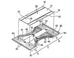
図3は、本実施形態の製造目的物である吸収性物品(パンツ型の使い捨ておむつ)の背側部側からの斜視図、図4は、該吸収性物品の展開状態を示す分解斜視図である。
Next, the manufacturing method of the absorbent article of this invention is demonstrated, referring drawings based on the preferable one Embodiment.
FIG. 3 is a perspective view from the back side of an absorbent article (pants-type disposable diaper) that is a manufacturing object of the present embodiment, and FIG. 4 is an exploded perspective view showing a developed state of the absorbent article. is there.
本実施形態の製造目的物であるおむつ20は、図3及び図4に示すように、吸収性本体30と、該吸収性本体30の非肌当接面側に位置する外装体40とを具備し、該外装体40における積層された二枚の繊維状シート41,42の一部に印刷模様23が施されている。以下に、このおむつ20について詳述する。
As shown in FIGS. 3 and 4, the
おむつ20は、着用者の腹側に配される腹側部Aと背側に配される背側部Bとその間に位置する股下部Cとを有し、腹側部Aの両側縁A1,A2と背側部Bの両側縁B1,B2とが、ヒートシール、高周波シール、超音波シール、接着剤等の公知の接合手段により接合されて、一対のレッグ開口部21、及びウエスト開口部22が形成されている。そして、おむつ20の背側部B側の外装体40(繊維状シート41,42)に、外部から認識可能な印刷模様23が施されている。
The
吸収性本体30は、縦長矩形状をなし、その長手方向を、おむつの長手方向、即ちおむつ20を平面状に展開した状態における腹側部Aと背側部Bとを結ぶ方向に一致させて、外装体40の中央部に接合されている。
The absorbent
吸収性本体30は、液透過性の表面シート31、液不透過性の裏面シート32及び液保持性の吸収性コア33からなる。吸収性コア33は、長手方向中央部の括れた砂時計状をなし、表面シート31及び裏面シート32間に挟持固定されている。吸収性本体30の長手方向左右両側部には、吸収性本体30の幅方向内方側に自由端を有し外方側に固定端を有する立体ガード34が設けられている。各立体ガード34には、複数本の立体ガード弾性部材(一本のみ図示)35が伸縮自在に固定されており、これにより立体ガード34が起立し、吸収性本体30の幅方向への液の流出が阻止される。
The absorbent
外装体40は、積層された二枚の繊維状シート(不織布)41,42から構成される。外装体40は、長手方向中央部分の両側縁が脚周りに沿うように凹状に形成されており、全体として長手方向中央部分が括れた形状(砂時計状の形状)を有している。
The
外装体40を構成する二枚の上記繊維状シート41,42間には、所定箇所に各種弾性部材が配されている。即ち、ウエスト開口部22には、その開口縁部に沿ってウエストギャザー形成用のウエスト弾性部材43が伸縮自在に配設されており、これにより、ウエスト開口部22に、その周縁部全周に亘って実質的に連続した環状のウエストギャザーが形成されている。また、腹側部A及び背側部Bそれぞれにおける胴周囲部Dには、おむつ20の幅方向に、複数の胴周囲部弾性部材44が所定間隔で配されている。胴周囲部Dとは、ウエスト弾性部材43が配された位置より下方で且つ股下部(両側部にレッグ開口形成用の凹欠部を有する部分)Cよりも上方に位置する部分である。また、着用者の脚廻りに配される一対のレッグ部45,45には、一方のレッグ部45から股下部Cを横断して他方のレッグ部45に亘るように、レッグギャザー形成用のレッグ部弾性部材46が配されている。
Various elastic members are arranged at predetermined positions between the two
本実施形態の吸収性物品(おむつ20)の製造方法について詳述する。おむつ20を製造するには、先ず、おむつの構成部材である、所望の印刷模様が施された外装体40及び吸収性本体30をそれぞれ製造する必要がある。
The manufacturing method of the absorbent article (diaper 20) of this embodiment is explained in full detail. In order to manufacture the
印刷模様が施された外装体40は、前述した本発明の通気性シートの製造方法を利用した外装体製造工程によって製造することができる。この外装体製造工程の一例について、図5を参照して説明する。
The
先ず、図5(a)に示すように、外装体を構成する二枚の繊維状シート41,42のうちの少なくとも一方の繊維状シート41に、ホットメルト接着剤を所定パターンで塗布して、ホットメルト接着剤の塗布部分H1及び非塗布部分H2を形成する。そして、前述したように、この塗布部分H1に、又は繊維状シート41のホットメルト接着剤の非塗布面における該塗布部分H1と対向する部分(繊維状シート41を介して該塗布部分H1と略反対側に位置する部分)に、所望の印刷模様23をインクジェット印刷により施す。
First, as shown in FIG. 5 (a), a hot melt adhesive is applied in a predetermined pattern to at least one of the two
次いで、図5(b)に示すように、ウエスト部弾性部材43、胴周囲部弾性部材44及びレッグ部弾性部材46を、それぞれ接着剤を介して間欠的に繊維状シート41と繊維状シート42(別の繊維状シート)との間に固定されるように、伸長状態で導入した後、両シート41,42同士を貼り合わせる(導入貼り合わせ工程)。この貼り合わせにおいては、繊維状シート41に施された印刷模様23が、外部に露出しないように注意する必要がある。即ち、繊維状シート41の印刷模様23が施された面が、繊維状シート42で被覆されるようにする。印刷模様23を外部に露出させると、印刷模様23の剥がれなどの不都合が生じるため、好ましくない。
Next, as shown in FIG. 5B, the waist
尚、レッグ部弾性部材46は、両連続シートの流れ方向Xに直交する方向Yに揺動させながら導入する。図5(b)に示す例においては、これらの弾性部材43、44及び46の導入の直後に、両シート41,42を互いに貼り合わせている。この導入貼り合わせ工程において、両シート41,42がホットメルト接着剤の塗布部分H1において互いに貼り合わされて接着領域P1が形成されると共に、両連続シートが互いに貼り合わされていない非接着領域P2が形成される。また、ウエスト部弾性部材43、胴周囲部弾性部材44及びレッグ部弾性部材46は、それぞれ接着領域P1においては、両シート41,42間に固定され、非接着領域P2においては、両シート41,42間に固定されない。
The leg
次いで、図5(c)に示すように、胴周囲部弾性部材44及びレッグ部弾性部材46を、所定の部位において切断する(切断工程)。この切断工程においては、各種公知の切断手段を用いることができ、例えばピンチカッター、ロータリーダイカッター、ヒートシールカッター、超音波カッター、ウォータージェットカッターなどを用いることができる。必要に応じ、切断工程の前又は後、あるいは切断工程と同時に、切断された胴周囲部弾性部材44及びレッグ部弾性部材46それぞれにおける所定の部位を、ヒートシールにより両シート41,42間に固定してもよい。
尚、図5(b)及び図5(c)では、説明容易のため、印刷模様23の図示を省略している。
Next, as shown in FIG. 5C, the trunk periphery
In FIG. 5B and FIG. 5C, the printed
このように、二枚の繊維状シート41,42の貼り合わせ工程において、糸ゴム等の弾性部材を図5に示すように両シート41,42間に挟み込むと、別途糸ゴムを挟む工程を簡略化できる点で好ましい。
Thus, in the process of bonding the two
以上のような工程を経て、積層シート40’が得られる。外装体40は、この積層シート40’から、レッグ部形成用の余分な部分47を切断除去すると共に、該積層シート40’を個々の外装体40の寸法に切断することにより、得られる。
Through the steps as described above, a laminated sheet 40 'is obtained. The
そして、本実施形態では、上述した外装体製造工程により製造された外装体40に、常法に従って別途製造した吸収性本体30を公知の接合手段により接合固定した後、腹側部Aの両側縁A1,A2と背側部Bの両側縁B1,B2とを接合する。これにより、パンツ型の使い捨ておむつであるおむつ20が得られる。
And in this embodiment, after fixing the absorptive
本実施形態のおむつ20の構成部材の形成材料について説明すると、吸収性本体30を構成する各部材、例えば、表面シート31、裏面シート32及び吸収性コア33等の形成材料、あるいは外装体40に配される各種弾性部材の形成材料としては、従来、この種の使い捨ておむつ等に用いられるものを特に制限なく用いることができる。尚、外装体40を構成する繊維状シートとしては、上述したように、不織布の他、合成紙、織物などを使用することができる。
The forming material of the constituent member of the
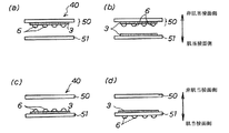
本発明に係る外装体製造工程についてさらに詳述すると、この外装体製造工程において、一枚以上の繊維状通気性シート(印刷模様が施された繊維状シート)と、一枚以上の別の繊維状シート(印刷模様が施されていない繊維状シート)とをそれぞれ貼り合わせるに当たっては、上述したように、繊維状通気性シートに施された印刷模様が外部に露出しないようにすればよく、この点を遵守すれば、これら複数枚のシートの積層順序等は特に制限されないが、特に好ましい外装体の形態として、図6に示す第1〜第3の形態が挙げられる。図6は、上記外装体40(積層された二枚の繊維状シートから構成された外装体)の展開状態を示す断面模式図である。 The exterior body manufacturing process according to the present invention will be described in further detail. In this exterior body manufacturing process, one or more fibrous breathable sheets (fibrous sheets with a printed pattern) and one or more other fibers are used. As described above, it is only necessary to prevent the printed pattern applied to the fibrous air-permeable sheet from being exposed to the outside. If the point is observed, the stacking order of the plurality of sheets is not particularly limited, but as a particularly preferable form of the exterior body, there are the first to third forms shown in FIG. FIG. 6 is a schematic cross-sectional view showing a developed state of the exterior body 40 (the exterior body composed of two laminated fibrous sheets).
第1の形態は、図6(a)及び図6(b)にそれぞれ示すように、外装体40の最外層50、即ち、外装体を構成する多層(各層は繊維状シートからなる)のうち、最も外側に位置する層50の肌当接面側にホットメルト接着剤の塗布部分(接着剤層3)が形成され、さらに、該接着剤層3にインク6が付着した、即ち、印刷模様が施された形態である。図6(a)と図6(b)との違いは、図6(b)では、最外層50に隣接する内層51(最外層に対し肌当接面側に位置する層)の非肌当接面側にも、接着剤層3が形成されている点である。これら第1の形態は、いずれも、その製造時においてインクの裏抜けが発生しないので、印刷模様の視認性、及び着用者の肌に対する安全性に優れ、また、接着剤層に直接インク(色材)が付着しているので色落ちにくいという特長を有する。また、接着剤層3の内層51との接着面のうち、インク6が付着した部分は該内層51と接着しないので、印刷模様が部分的に浮かび上がり、該印刷模様を立体的に見せることができる。また、図6(a)に示す形態は、接着剤層の厚みが比較的薄いので、特にシートの柔軟性に優れており、図6(b)に示す形態は、接着剤層を多層にしているので、特に色落ち防止効果に優れる。
As shown in FIGS. 6 (a) and 6 (b), the first form is the
第2の形態は、図6(c)に示すように、外装体40の最外層50に隣接する内層51の非肌当接面側に接着剤層3が形成され、さらに、該接着剤層3にインク6が付着した形態である。この第2の形態も、第1の形態と同様の優れた効果が得られる。
In the second embodiment, as shown in FIG. 6C, the
第3の形態は、図6(d)に示すように、外装体40の最外層50に隣接する内層51の非肌当接面側に接着剤層3が形成され、また、該内層51の肌当接面側における該接着剤層3と対向する部分にインク6が付着した形態である。この第3の形態は、上記第1及び第2の形態と同様に、インクの裏抜け防止性及び色落ち防止性に優れ、肌にインクが付着しにくい。
In the third embodiment, as shown in FIG. 6D, the
以上、本発明の実施形態について説明したが、本発明は、上述した実施形態に制限されず、本発明の趣旨を逸脱しない範囲で種々の変更が可能である。
例えば、インクジェット印刷後、そのインク付着部分(印刷模様)に、比較的少量のホットメルト接着剤を塗布(オーバーコート)することができる。最も好ましい形態としては、図6(c)におけるインク6の上にホットメルト接着剤をオーバーコートすることであり、このようにすることで、インクの定着性が高まり、繊維状シート同士の接着性が高まる。
また、印刷模様近辺部分のみに、流れ方向に対して間欠的にホットメルト接着剤を塗布すると、柔軟な外装となる点で好ましい。
As mentioned above, although embodiment of this invention was described, this invention is not restrict | limited to embodiment mentioned above, A various change is possible in the range which does not deviate from the meaning of this invention.
For example, after ink jet printing, a relatively small amount of hot melt adhesive can be applied (overcoated) to the ink adhering portion (printed pattern). The most preferable mode is to overcoat a hot melt adhesive on the
Moreover, it is preferable that a hot melt adhesive is intermittently applied only in the vicinity of the printed pattern in the flow direction in that a flexible exterior is obtained.
また、上述した吸収性物品(おむつ20)の製造方法の実施形態では、外装体を構成する二枚のシートとして、同種の上記繊維状シートを用いたが、印刷模様を施さない方のシートとしては、上記繊維状シート以外のシート、例えば、未開孔のフィルムや微細孔を有するシート等を用いることもできる。このようなシートを用いた場合には、上記吸収性本体30の構成部材から上記裏面シート32を排除し、液透過性の上記表面シート31のみで該吸収性本体30の表裏面を形成するようにしてもよい。
Moreover, in embodiment of the manufacturing method of the absorbent article (diaper 20) mentioned above, although the said same kind of fibrous sheet was used as two sheets which comprise an exterior body, as a sheet | seat which does not give a printing pattern May be a sheet other than the fibrous sheet, for example, an unopened film or a sheet having fine holes. When such a sheet is used, the
また、上述した吸収性物品(おむつ20)の製造方法の実施形態では、外装体が2枚の前記繊維状シートで構成されていたが、外装体は一枚の繊維状シートで構成されていてもよい。この場合、印刷模様が施された一枚の繊維状シートを、上記吸収性本体30に直接接合させればよい。
Moreover, in embodiment of the manufacturing method of the absorbent article (diaper 20) mentioned above, although the exterior body was comprised with the said 2 fibrous sheet, the exterior body is comprised with the sheet of one fibrous sheet. Also good. In this case, a single fibrous sheet on which a printed pattern has been applied may be directly joined to the absorbent
また、本発明の吸収性物品の製造方法は、上述したパンツ型の使い捨ておむつの他、一対のファスニングテープが設けられたいわゆる展開型の使い捨ておむつ、さらには、生理用ナプキン、個装用不織布等にも適用することができる。 Further, the method of manufacturing an absorbent article of the present invention, other disposable diaper pants type described above, so-called development-type disposable diaper in which a pair of fastening tapes are provided, further, physiology napkins, individual wearing non-woven fabric It can also be applied to.
1,1’,41,42…繊維状シート、2…接着剤塗布装置、3…接着剤層(ホットメルト接着剤の塗布部分)、4…印刷台、5…インクジェットヘッド、6…インク(印刷模様)、7,7’…通気性シート、8…乾燥装置、9,10…プレスローラ、20…パンツ型の使い捨ておむつ、21…レッグ開口部、22…ウエスト開口部、23…印刷模様、30…吸収性本体、31…表面シート、32…裏面シート、33…吸収性コア、34…立体ガード、35…立体ガード弾性部材、40…外装体、40’…積層シート、43…ウエスト部弾性部材、44…胴周囲部弾性部材、45…レッグ部、46…レッグ部弾性部材、50…最外層、51…内層(最外層に隣接する層)、A…腹側部、B…背側部、C…股下部、D…胴周囲部
DESCRIPTION OF
Claims (7)
繊維状シートの一方の面にホットメルト接着剤を塗布した後、該ホットメルト接着剤の塗布部分に又は該繊維状シートの他方の面における該塗布部分と対向する部分に、前記印刷模様をインクジェット印刷により施す工程と、
前記印刷模様を施された前記繊維状シートを、施された該印刷模様が外部に露出しないように前記吸収性本体に前記外装体として配置する工程とを有する吸収性物品の製造方法。 A method for producing an absorbent article comprising an absorbent main body and an exterior body positioned on the non-skin contact surface side of the absorbent main body,
After the hot melt adhesive is applied to one surface of the fibrous sheet, the printed pattern is ink-jetted on the applied portion of the hot melt adhesive or on the portion facing the applied portion on the other surface of the fibrous sheet. A process of printing,
And arranging the fibrous sheet having the printed pattern on the absorbent main body as the exterior body so that the applied printed pattern is not exposed to the outside.
Priority Applications (5)
| Application Number | Priority Date | Filing Date | Title |
|---|---|---|---|
| JP2004290697A JP4312140B2 (en) | 2004-10-01 | 2004-10-01 | Method for producing breathable sheet and method for producing absorbent article |
| CNB2005100992224A CN100534781C (en) | 2004-10-01 | 2005-09-09 | Process of producing breathable sheet and producing an absorbent article comprising the breathable sheet |
| US11/229,613 US7992994B2 (en) | 2004-10-01 | 2005-09-20 | Process of producing breathable sheet and process of producing absorbent article |
| EP05021010A EP1642557B1 (en) | 2004-10-01 | 2005-09-27 | Process of producing breathable sheet and producing an absorbent article comprising the breathable sheet |
| DE602005004851T DE602005004851T2 (en) | 2004-10-01 | 2005-09-27 | A method of making a breathable layer and an absorbent article comprising this layer |
Applications Claiming Priority (1)
| Application Number | Priority Date | Filing Date | Title |
|---|---|---|---|
| JP2004290697A JP4312140B2 (en) | 2004-10-01 | 2004-10-01 | Method for producing breathable sheet and method for producing absorbent article |
Publications (3)
| Publication Number | Publication Date |
|---|---|
| JP2006103068A JP2006103068A (en) | 2006-04-20 |
| JP2006103068A5 JP2006103068A5 (en) | 2006-10-05 |
| JP4312140B2 true JP4312140B2 (en) | 2009-08-12 |
Family
ID=35447727
Family Applications (1)
| Application Number | Title | Priority Date | Filing Date |
|---|---|---|---|
| JP2004290697A Expired - Fee Related JP4312140B2 (en) | 2004-10-01 | 2004-10-01 | Method for producing breathable sheet and method for producing absorbent article |
Country Status (5)
| Country | Link |
|---|---|
| US (1) | US7992994B2 (en) |
| EP (1) | EP1642557B1 (en) |
| JP (1) | JP4312140B2 (en) |
| CN (1) | CN100534781C (en) |
| DE (1) | DE602005004851T2 (en) |
Families Citing this family (49)
| Publication number | Priority date | Publication date | Assignee | Title |
|---|---|---|---|---|
| EP1295711B1 (en) | 2001-09-19 | 2006-04-12 | The Procter & Gamble Company | A color printed laminated structure, absorbent article comprising the same and process for manufacturing the same |
| US20070239126A1 (en) * | 2006-04-11 | 2007-10-11 | Kimberly-Clark Worldwide, Inc. | Absorbent article printed using digital printing technology and a method of printing |
| US8780936B2 (en) * | 2006-05-22 | 2014-07-15 | Qualcomm Incorporated | Signal acquisition for wireless communication systems |
| WO2008016021A1 (en) | 2006-07-31 | 2008-02-07 | Daio Paper Corporation | Paper diaper |
| WO2008016020A1 (en) * | 2006-07-31 | 2008-02-07 | Daio Paper Corporation | Pants-type paper diaper |
| US8748691B2 (en) | 2006-10-16 | 2014-06-10 | The Procter & Gamble Company | Three-dimensional printed article |
| US20080221543A1 (en) * | 2007-03-06 | 2008-09-11 | Todd Wilkes | Disposable absorbent product having a graphic indicator |
| US8262633B2 (en) * | 2008-08-08 | 2012-09-11 | The Procter And Gamble Company | Absorbent article having a multi-component visual signal |
| US20110050764A1 (en) * | 2009-08-26 | 2011-03-03 | Henryk Birecki | Hard imaging device and method thereof |
| US20110146900A1 (en) * | 2009-12-18 | 2011-06-23 | Marcille Faye Ruman | Manufacture And Assembly Of Absorbent Articles With Multiple Printed Components |
| JP5486290B2 (en) * | 2009-12-22 | 2014-05-07 | 花王株式会社 | Absorbent articles |
| JP5337688B2 (en) * | 2009-12-28 | 2013-11-06 | ユニ・チャーム株式会社 | Disposable diaper manufacturing method |
| US20110162989A1 (en) | 2010-01-06 | 2011-07-07 | Ducker Paul M | Ultra thin laminate with particulates in dense packages |
| US9549858B2 (en) * | 2010-01-06 | 2017-01-24 | Ching-Yun Morris Yang | Ultra-thin absorbent article |
| JP5569036B2 (en) * | 2010-02-26 | 2014-08-13 | セイコーエプソン株式会社 | Inkjet printing method |
| JP5569035B2 (en) * | 2010-02-26 | 2014-08-13 | セイコーエプソン株式会社 | Inkjet printing method |
| JP5928679B2 (en) * | 2011-07-14 | 2016-06-01 | セイコーエプソン株式会社 | Inkjet printing apparatus and method for producing printed matter |
| JP5181049B2 (en) * | 2011-08-10 | 2013-04-10 | 大王製紙株式会社 | Absorbent article manufacturing apparatus and manufacturing method |
| WO2013032896A1 (en) | 2011-08-26 | 2013-03-07 | Taylor Corporation | Absorbent articles having variable data thereon and systems and methods for printing such articles |
| WO2013051971A1 (en) * | 2011-10-05 | 2013-04-11 | Sca Hygiene Products Ab | Method of applying structural elements to an absorbent article |
| US8950327B2 (en) | 2011-12-07 | 2015-02-10 | Lingraph | Method of printing onto a substrate |
| WO2013173261A2 (en) * | 2012-05-15 | 2013-11-21 | The Procter & Gamble Company | Absorbent articles with uniform graphics |
| JP5730825B2 (en) * | 2012-07-13 | 2015-06-10 | 富士フイルム株式会社 | Coating apparatus and inkjet recording apparatus |
| US8876279B2 (en) | 2012-08-31 | 2014-11-04 | The Procter & Gamble Company | Process and apparatus for printing assembled absorbent articles with custom graphics |
| KR101416474B1 (en) * | 2012-09-04 | 2014-08-06 | 피에스케이 주식회사 | Apparatus and method for manufacturing light guiding plate |
| US9004675B2 (en) | 2013-04-04 | 2015-04-14 | Nike, Inc. | Image correction with 3D printing |
| US9492336B2 (en) | 2013-10-18 | 2016-11-15 | The Procter & Gamble Company | Absorbent article having a composite web with visual signal thereon |
| JP5914566B2 (en) * | 2014-04-28 | 2016-05-11 | ユニ・チャーム株式会社 | Composite sheet manufacturing method and composite sheet manufacturing apparatus |
| CN104002549B (en) * | 2014-05-26 | 2017-07-18 | 杭州新余宏机械有限公司 | The printed on line device and printed on line method of pattern on sanitary napkin |
| JP5951867B2 (en) * | 2014-09-29 | 2016-07-13 | 花王株式会社 | Absorbent article inspection method |
| JP5842081B1 (en) * | 2014-11-28 | 2016-01-13 | ユニ・チャーム株式会社 | Sheet member manufacturing method and sheet member manufacturing apparatus |
| WO2016084245A1 (en) * | 2014-11-28 | 2016-06-02 | ユニ・チャーム株式会社 | Method for manufacturing sheet and method for drying same |
| WO2016084246A1 (en) * | 2014-11-28 | 2016-06-02 | ユニ・チャーム株式会社 | Composite sheet production method and composite sheet production device |
| CN104532485A (en) * | 2014-12-10 | 2015-04-22 | 弘博纤维材料科技(昆山)有限公司 | Color-grain double-component composite non-woven fabric and manufacturing method thereof |
| WO2016092708A1 (en) * | 2014-12-12 | 2016-06-16 | 山田 菊夫 | Disposable garment and absorbent body |
| WO2016093035A1 (en) * | 2014-12-12 | 2016-06-16 | 山田 菊夫 | Disposable garment |
| JP6072992B1 (en) * | 2015-05-12 | 2017-02-01 | 山田 菊夫 | Disposable textile products and disposable textile products using the same |
| JP2016221255A (en) * | 2015-05-27 | 2016-12-28 | ユニ・チャーム株式会社 | Disposable diaper |
| JP3222578U (en) * | 2015-05-27 | 2019-08-08 | ユニ・チャーム株式会社 | Disposable diapers |
| TWI743042B (en) * | 2015-07-28 | 2021-10-21 | 山田菊夫 | Disposable clothing |
| JPWO2017026018A1 (en) * | 2015-08-07 | 2017-08-10 | 山田 菊夫 | Method for manufacturing disposable clothing for lower body |
| US20170056255A1 (en) * | 2015-08-26 | 2017-03-02 | The Procter & Gamble Company | Absorbent article with signals |
| JP2017046750A (en) * | 2015-08-31 | 2017-03-09 | 王子ホールディングス株式会社 | Absorbent article |
| WO2017082206A1 (en) * | 2015-11-12 | 2017-05-18 | 山田菊夫 | Disposable bottom garment |
| WO2017095578A1 (en) | 2015-11-30 | 2017-06-08 | The Procter & Gamble Company | Absorbent article with colored topsheet |
| JP2016221236A (en) * | 2015-12-17 | 2016-12-28 | ユニ・チャーム株式会社 | Disposable diaper |
| CN205649589U (en) * | 2016-01-12 | 2016-10-19 | 山田菊夫 | Disposable article |
| GB2587546A (en) * | 2018-04-30 | 2021-03-31 | Kimberly Clark Co | Absorbent article |
| CN114423618B (en) * | 2019-10-15 | 2024-03-29 | 株式会社瑞光 | Printing method in manufacturing disposable wearing article |
Family Cites Families (19)
| Publication number | Priority date | Publication date | Assignee | Title |
|---|---|---|---|---|
| GB8517318D0 (en) | 1985-07-09 | 1985-08-14 | Willett Int Ltd | Coding of absorbent materials |
| CA2049571C (en) * | 1990-10-19 | 2004-01-13 | Kent D. Vincent | High definition thermal ink-jet printer |
| DE69429839T2 (en) * | 1993-05-10 | 2002-06-27 | Canon Kk | Printing stock, manufacturing process, textile printing process and ink jet printing apparatus |
| US5458590A (en) * | 1993-12-20 | 1995-10-17 | Kimberly-Clark Corporation | Ink-printed, low basis weight nonwoven fibrous webs and method |
| US6824839B1 (en) * | 1995-08-25 | 2004-11-30 | Avery Dennison Corporation | Water-activated polymers and adhesive image transfer technique |
| US5793398A (en) | 1995-11-29 | 1998-08-11 | Levi Strauss & Co. | Hot melt ink jet shademarking system for use with automatic fabric spreading apparatus |
| DE69823654T8 (en) | 1997-03-31 | 2005-09-29 | Neenah Paper, Inc. | TWO-LAY PRINTABLE MATERIAL |
| JP3592044B2 (en) * | 1997-08-01 | 2004-11-24 | キヤノン株式会社 | Thermal bonding medium for inkjet, thermal bonding method, thermal bonding body, and method for manufacturing thermal bonding medium for inkjet |
| JP2000000266A (en) | 1998-06-16 | 2000-01-07 | Oji Paper Co Ltd | Printing of absorptive wearing article and absorptive wearing article subjected to printing |
| EP1044821B1 (en) * | 1999-04-14 | 2004-03-03 | Hewlett-Packard Company, A Delaware Corporation | Photo media printing |
| US20030048343A1 (en) * | 2001-08-30 | 2003-03-13 | Anderson Brian L. | Process for preparing a laminated ink jet print |
| US7303651B2 (en) * | 2001-11-08 | 2007-12-04 | Oji Paper Co., Ltd. | Ink jet recording paper |
| JP4382364B2 (en) * | 2002-04-24 | 2009-12-09 | 株式会社東芝 | Liquid ink |
| US7824029B2 (en) * | 2002-05-10 | 2010-11-02 | L-1 Secure Credentialing, Inc. | Identification card printer-assembler for over the counter card issuing |
| JP2004175052A (en) * | 2002-11-29 | 2004-06-24 | Sony Corp | Medium to be recorded by ink jetting, ink jet imaging method, and printed matter |
| US6857737B2 (en) * | 2002-12-23 | 2005-02-22 | 3M Innovative Properties Company | UV ink printed graphic article |
| US6957884B2 (en) | 2002-12-27 | 2005-10-25 | Kinberly-Clark Worldwide, Inc. | High-speed inkjet printing for vibrant and crockfast graphics on web materials or end-products |
| JP3954549B2 (en) * | 2003-09-03 | 2007-08-08 | 株式会社リブドゥコーポレーション | Pants-type disposable diapers |
| US7718844B2 (en) * | 2004-06-30 | 2010-05-18 | Kimberly-Clark Worldwide, Inc. | Absorbent article having an interior graphic |
-
2004
- 2004-10-01 JP JP2004290697A patent/JP4312140B2/en not_active Expired - Fee Related
-
2005
- 2005-09-09 CN CNB2005100992224A patent/CN100534781C/en not_active Expired - Fee Related
- 2005-09-20 US US11/229,613 patent/US7992994B2/en not_active Expired - Fee Related
- 2005-09-27 DE DE602005004851T patent/DE602005004851T2/en active Active
- 2005-09-27 EP EP05021010A patent/EP1642557B1/en not_active Expired - Fee Related
Also Published As
| Publication number | Publication date |
|---|---|
| JP2006103068A (en) | 2006-04-20 |
| US20060070701A1 (en) | 2006-04-06 |
| CN100534781C (en) | 2009-09-02 |
| DE602005004851D1 (en) | 2008-04-03 |
| DE602005004851T2 (en) | 2008-06-12 |
| EP1642557B1 (en) | 2008-02-20 |
| CN1754690A (en) | 2006-04-05 |
| US7992994B2 (en) | 2011-08-09 |
| EP1642557A1 (en) | 2006-04-05 |
Similar Documents
| Publication | Publication Date | Title |
|---|---|---|
| JP4312140B2 (en) | Method for producing breathable sheet and method for producing absorbent article | |
| CN103180143B (en) | Produce the method for composite multi-layer printing absorbent article | |
| JP4523860B2 (en) | Absorbent articles | |
| JP5102504B2 (en) | Absorbent articles | |
| JP2021007749A (en) | Printed components and methods for making the same | |
| WO2005023160A1 (en) | Pants type disposable diaper and method of manufacturing the diaper | |
| CN103168123A (en) | Method of producing a multi-layered printed absorbent article | |
| KR101724173B1 (en) | Matching absorbent article components for a uniform appearance | |
| KR20110008281A (en) | Absorptive article and method of manufacturing absorptive article | |
| JP2019080672A (en) | Absorbent article | |
| CN103298438A (en) | Fastening means for an absorbent product | |
| JP7252433B2 (en) | Printing method in the manufacture of disposable wearing articles | |
| JP5799191B1 (en) | Composite sheet manufacturing apparatus and composite sheet manufacturing method | |
| JP4805393B2 (en) | Absorbent article manufacturing apparatus and manufacturing method | |
| JP5978405B1 (en) | Absorbent article manufacturing method and absorbent article manufacturing apparatus | |
| TW201733540A (en) | Method for manufacture of absorbent article | |
| JP4805395B2 (en) | Absorbent article manufacturing apparatus and manufacturing method | |
| JP4342614B2 (en) | Absorbent wearing articles | |
| JP4516297B2 (en) | Absorbent article and manufacturing method thereof | |
| JP5842081B1 (en) | Sheet member manufacturing method and sheet member manufacturing apparatus | |
| JP2011218226A (en) | Device and method for manufacturing absorbent article | |
| JP7304130B2 (en) | absorbent article | |
| JP2002011045A (en) | Manufacturing method of absorbent goods | |
| JP2008200169A (en) | Method to apply adhesive and method to manufacture absorbent article | |
| WO2011122625A1 (en) | Device and method for manufacturing absorptive article |
Legal Events
| Date | Code | Title | Description |
|---|---|---|---|
| A521 | Request for written amendment filed |
Free format text: JAPANESE INTERMEDIATE CODE: A523 Effective date: 20060823 |
|
| A621 | Written request for application examination |
Free format text: JAPANESE INTERMEDIATE CODE: A621 Effective date: 20060823 |
|
| A977 | Report on retrieval |
Free format text: JAPANESE INTERMEDIATE CODE: A971007 Effective date: 20090129 |
|
| A131 | Notification of reasons for refusal |
Free format text: JAPANESE INTERMEDIATE CODE: A131 Effective date: 20090203 |
|
| A521 | Request for written amendment filed |
Free format text: JAPANESE INTERMEDIATE CODE: A523 Effective date: 20090306 |
|
| TRDD | Decision of grant or rejection written | ||
| A01 | Written decision to grant a patent or to grant a registration (utility model) |
Free format text: JAPANESE INTERMEDIATE CODE: A01 Effective date: 20090512 |
|
| A01 | Written decision to grant a patent or to grant a registration (utility model) |
Free format text: JAPANESE INTERMEDIATE CODE: A01 |
|
| A61 | First payment of annual fees (during grant procedure) |
Free format text: JAPANESE INTERMEDIATE CODE: A61 Effective date: 20090512 |
|
| FPAY | Renewal fee payment (event date is renewal date of database) |
Free format text: PAYMENT UNTIL: 20120522 Year of fee payment: 3 |
|
| R151 | Written notification of patent or utility model registration |
Ref document number: 4312140 Country of ref document: JP Free format text: JAPANESE INTERMEDIATE CODE: R151 |
|
| FPAY | Renewal fee payment (event date is renewal date of database) |
Free format text: PAYMENT UNTIL: 20120522 Year of fee payment: 3 |
|
| FPAY | Renewal fee payment (event date is renewal date of database) |
Free format text: PAYMENT UNTIL: 20130522 Year of fee payment: 4 |
|
| R250 | Receipt of annual fees |
Free format text: JAPANESE INTERMEDIATE CODE: R250 |
|
| FPAY | Renewal fee payment (event date is renewal date of database) |
Free format text: PAYMENT UNTIL: 20140522 Year of fee payment: 5 |
|
| R250 | Receipt of annual fees |
Free format text: JAPANESE INTERMEDIATE CODE: R250 |
|
| R250 | Receipt of annual fees |
Free format text: JAPANESE INTERMEDIATE CODE: R250 |
|
| R250 | Receipt of annual fees |
Free format text: JAPANESE INTERMEDIATE CODE: R250 |
|
| R250 | Receipt of annual fees |
Free format text: JAPANESE INTERMEDIATE CODE: R250 |
|
| R250 | Receipt of annual fees |
Free format text: JAPANESE INTERMEDIATE CODE: R250 |
|
| R250 | Receipt of annual fees |
Free format text: JAPANESE INTERMEDIATE CODE: R250 |
|
| LAPS | Cancellation because of no payment of annual fees |