JP4307351B2 - Power supply system and control method thereof - Google Patents
Power supply system and control method thereof Download PDFInfo
- Publication number
- JP4307351B2 JP4307351B2 JP2004258497A JP2004258497A JP4307351B2 JP 4307351 B2 JP4307351 B2 JP 4307351B2 JP 2004258497 A JP2004258497 A JP 2004258497A JP 2004258497 A JP2004258497 A JP 2004258497A JP 4307351 B2 JP4307351 B2 JP 4307351B2
- Authority
- JP
- Japan
- Prior art keywords
- power supply
- drive system
- system power
- supply unit
- unit
- Prior art date
- Legal status (The legal status is an assumption and is not a legal conclusion. Google has not performed a legal analysis and makes no representation as to the accuracy of the status listed.)
- Active
Links
Images

Landscapes
- Accessory Devices And Overall Control Thereof (AREA)
- Control Or Security For Electrophotography (AREA)
- Direct Current Feeding And Distribution (AREA)
Description
本発明は、複数の電源ユニットを備えた電源システムおよびその制御方法に関し、特に画像形成装置の電源システムおよびその制御方法に関するものである。 The present invention relates to a power supply system including a plurality of power supply units and a control method thereof, and more particularly to a power supply system of an image forming apparatus and a control method thereof.
ファクシミリ、複写機および電子写真方式のプリンタ等の画像形成装置においても、近年省エネルギー化の要望が強く、画像形成動作中以外の待機状態では、画像形成装置の消費電力を低減させることが要望されている。 In recent years, there has been a strong demand for energy saving in image forming apparatuses such as facsimiles, copiers, and electrophotographic printers, and there is a demand for reducing the power consumption of the image forming apparatus in a standby state other than during the image forming operation. Yes.
そこで、従来の画像形成装置では、待機状態の消費電力を低減させるために、例えば下記特許文献1などのように、画像形成装置の各構成ユニットに対して電力を供給する複数の電源ユニットを有し、待機状態においては必要最低限のユニット、特に制御ユニットのような機能上必要なユニットへのみ電力を供給し、その他画像形成動作中にのみ動作させる必要のあるユニットへの電力を遮断することで、画像形成装置としてのシステム全体の消費電力を低減させている。 Therefore, in order to reduce power consumption in the standby state, the conventional image forming apparatus has a plurality of power supply units that supply power to each component unit of the image forming apparatus, for example, as in Patent Document 1 below. In the standby state, power is supplied only to the minimum necessary units, in particular, units necessary for functions such as the control unit, and power to other units that need to be operated only during the image forming operation is cut off. Thus, the power consumption of the entire system as the image forming apparatus is reduced.
通常このような場合、画像形成装置内外に有する画像形成に必要なユニット、例えば画像形成を行うプロセス電圧電源ユニット、画像形成時に記録紙等を搬送する搬送系ユニット、作像ユニット、各種オプション類等、主に駆動系ユニットへの電力供給を行う電源ユニットへの通電を、リレー等のスイッチング手段により遮断することで実現している。 Usually, in such a case, a unit necessary for image formation inside and outside the image forming apparatus, for example, a process voltage power supply unit that performs image formation, a transport system unit that transports recording paper or the like during image formation, an image forming unit, various options, etc. This is realized by interrupting the energization of the power supply unit that mainly supplies power to the drive system unit by switching means such as a relay.
このように、待機状態において、駆動系ユニットの電源ユニットの通電を遮断することで、駆動系ユニットの電源および画像形成動作にのみ必要なユニットが全て停止し、大幅に電力を低減させる事が出来る。 In this way, by shutting off the power of the power supply unit of the drive system unit in the standby state, all the units necessary only for the power supply of the drive system unit and the image forming operation are stopped, and the power can be greatly reduced. .
なお、通常これらのユニットの駆動には大電力を要するため、大型の電源ユニットが備えられる。
上記のような場合、制御系ユニットの電源ユニットは常時動作しており、その制御回路によって駆動系ユニットの電源ユニットの駆動/停止をコントロールしている。 In such a case, the power supply unit of the control system unit is always operating, and the drive / stop of the power supply unit of the drive system unit is controlled by the control circuit.
従って、画像形成動作等の要求に応じて駆動系電源ユニットを駆動させて所定の動作を行い、待機状態に入ったところで制御回路からの要求に従って駆動系電源ユニットの停止を行い、省電力モードに入る。 Therefore, the drive system power supply unit is driven in response to a request such as an image forming operation to perform a predetermined operation, and when the standby state is entered, the drive system power supply unit is stopped according to a request from the control circuit, and the power saving mode is set. enter.
これらの制御は、画像形成装置に供給される、商用電源電圧が一定である事が前提となっており、この商用電源電圧が何らかの理由で変動してしまう場合には、特に大電力を要する大型の駆動系電源ユニットがより大きな影響を受ける。 These controls are based on the premise that the commercial power supply voltage supplied to the image forming apparatus is constant. If this commercial power supply voltage fluctuates for some reason, a large-sized power that requires a large amount of power is required. The drive system power supply unit is greatly affected.
つまり、商用電源電圧が所定の電圧値つまり電源ユニットが許容出来る電圧を下回ってしまった場合や、瞬間的な電圧遮断が生じた場合、電源ユニットは、同量の電力を出力し続けるために、電源ユニット内でより多くの電流を制御する必要に迫られ、過電流により安全回路が動作して電源ユニットが停止してしまう場合がある。 In other words, when the commercial power supply voltage falls below a predetermined voltage value, that is, the voltage that the power supply unit can tolerate, or when an instantaneous voltage interruption occurs, the power supply unit continues to output the same amount of power, There is a case where it is necessary to control more current in the power supply unit, and the safety circuit operates due to overcurrent, and the power supply unit may stop.
このような現象は、電源ユニットの規模によらず発生し得る現象であるが、比較的小電力な制御系電源ユニットよりも、むしろ大電力が要求される駆動系電源ユニットの方がより発生しやすい。なぜなら、小電力であれば、コンデンサや電池などで比較的容易に対策を講じる事が可能なのに対し、大電力をまかなうのに必要なコンデンサや電池は現実的な範囲を超えてしまうためである。 Such a phenomenon can occur regardless of the scale of the power supply unit, but it is more likely to occur in the drive system power supply unit that requires high power than in the control system power supply unit with relatively low power. Cheap. This is because it is possible to take countermeasures relatively easily with a capacitor, a battery, or the like if the power is low, but the capacitor or battery required to cover the high power exceeds the practical range.
商用電源電圧が変動してしまう例として、オフィスやマンションなどのように元々居住用として作られた部屋で、多数のOA機器を用いるケースの増加が挙げられる。このような電源事情の良くない環境下では、過大電流による電源電圧の異常な低下といった不都合が多発しやすい。 As an example in which the commercial power supply voltage fluctuates, there is an increase in the number of cases in which a large number of OA devices are used in a room originally made for residential use such as an office or a condominium. In such an environment where the power supply situation is not good, inconveniences such as an abnormal drop in the power supply voltage due to an excessive current tend to occur frequently.
また、電源事情の良くない場所/地域、例えば工場内に置かれた環境や近くに工場がある場合など、商用電源電圧の低下や一時的な遮断、また電圧波形に歪みが生じてしまうことがある。 In addition, in places / areas where power supply conditions are not good, for example, when the environment is located in a factory or when there is a factory nearby, the commercial power supply voltage may be reduced or temporarily cut off, or the voltage waveform may be distorted. is there.
このような状況では、最も電力を消費する機器の一つでもある画像形成装置においても、駆動系電源ユニットのみが停止してしまい、自動復帰できずにエラーとなってしまうなどの問題が生じ、何らかの対応策が求められていた。 In such a situation, even in an image forming apparatus that is one of the devices that consumes the most power, only the drive system power supply unit stops, causing problems such as an error that cannot be automatically restored, Some kind of countermeasure was required.
さらにまた別の問題として、駆動系電源ユニットは、画像形成装置本体に接続される外部ユニット、例えば給紙口、排紙口に接続されるオプションユニットなどにも電源供給を行っており、画像形成装置本体外部に接続のためのインターフェースを持つ場合が多い。この場合、ユーザーの誤操作、例えば電源を投入したままインターフェースを抜き差ししてしまったり、何らかの原因で駆動電源出力を短絡させてしまったり等、駆動系電源ユニットが何らかの安全回路動作により停止させてしまうケースもあった。 As another problem, the drive system power supply unit also supplies power to an external unit connected to the image forming apparatus main body, for example, an optional unit connected to a paper feed port or a paper discharge port. In many cases, an interface for connection is provided outside the main body of the apparatus. In this case, the drive system power supply unit may be stopped due to some safety circuit operation, such as user's misoperation, such as plugging / unplugging the interface with the power on, or shorting the drive power output for some reason There was also.
本発明は、このような問題点に鑑みて為されたものであり、その目的とする処は、商用電源電圧変動やユーザーの誤操作による電力が供給される負荷側の異常等が画像形成装置に与える影響を極力回避することで、ユーザビリティを向上させることができる電源システムおよびその制御方法を提供することにある。 The present invention has been made in view of the above problems, and the object of the present invention is that an abnormality in the load side to which power is supplied due to a fluctuation in commercial power supply voltage or a user's erroneous operation is caused in the image forming apparatus. An object of the present invention is to provide a power supply system and a control method thereof that can improve usability by avoiding the influence as much as possible.
本発明は、下記の技術的構成により前記目的を達成できたものである。 The present invention has achieved the above object by the following technical configuration.
(1)記録紙上に画像を形成するための駆動系ユニットと、前記駆動系ユニットの動作を制御するコントローラと、を有する画像形成装置の電源システムであって、商用電源と接続され、前記駆動系ユニットに電力を供給する駆動系電源ユニットと、前記商用電源と接続され、前記コントローラに電力を供給する制御系電源ユニットと、前記駆動系電源ユニットのON/OFFを制御するとともに前記駆動系電源ユニットの出力電圧をモニタする駆動系電源制御回路と、を有し、前記制御系電源ユニットは、前記駆動系電源制御回路を動作させるために前記駆動系電源制御回路にも電力を供給し、前記駆動系電源制御回路は、前記駆動系電源ユニットの出力電圧が正常な値でない場合、前記駆動系電源ユニットをOFFし、前記商用電源の変動や誤操作による前記駆動系電源ユニットのシャットダウンが解除されるに十分な待機時間の経過後、前記駆動系電源ユニットをONすることにより、前記駆動系電源ユニットを再起動することを特徴とする電源システム。 (1) A power supply system of an image forming apparatus having a drive system unit for forming an image on a recording sheet and a controller for controlling the operation of the drive system unit, which is connected to a commercial power supply, and the drive system A drive system power supply unit that supplies power to the unit; a control system power supply unit that is connected to the commercial power supply and supplies power to the controller; and controls the ON / OFF of the drive system power supply unit and the drive system power supply unit A drive system power supply control circuit that monitors the output voltage of the drive system, wherein the control system power supply unit also supplies power to the drive system power supply control circuit to operate the drive system power supply control circuit, and the drive system power supply control circuit, when the output voltage of the drive system power supply unit is not a normal value, and OFF the drive system power supply unit, variations of the commercial power source And after a sufficient waiting time the shutdown of the drive system power supply unit according to erroneous operation is released, by ON the drive system power supply unit, power supply system, characterized by restarting the drive system power supply unit .
本発明によれば、商用電源電圧変動やユーザーの誤操作による電力が供給される負荷側の異常等が画像形成装置に与える影響を極力回避することで、ユーザビリティを向上させることができる電源システムおよびその制御方法を提供することができる。 Advantageous Effects of Invention According to the present invention, a power supply system capable of improving usability by avoiding as much as possible the influence on the image forming apparatus caused by abnormalities on the load side to which power is supplied due to fluctuations in commercial power supply voltage or user's erroneous operation, and the like A control method can be provided.
以下本発明の実施例について、図面を参照しながら説明する。 Embodiments of the present invention will be described below with reference to the drawings.
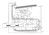
図1は電子写真プロセスを用いた画像形成装置の概略構成図であり、例えばレーザービームプリンタの場合を示している。 FIG. 1 is a schematic configuration diagram of an image forming apparatus using an electrophotographic process, and shows a case of a laser beam printer, for example.
レーザービームプリンタ本体101(以下、本体101)は、記録紙Sを収納する給紙カセット102を有し、給紙カセット102の記録紙Sの有無を検知するカセット有無センサ103、給紙カセット102の記録紙Sのサイズを検知するカセットサイズセンサ104(複数個のマイクロスイッチで構成される)、給紙カセット102から記録紙Sを繰り出す給紙ローラ105aおよび搬送ローラ対105b、105c、105d等が設けられている。そして、給紙ローラ105a、搬送ローラ対105b、105c、105dの下流には記録紙Sを同期搬送するレジストローラ対106が設けられている。
The laser beam printer main body 101 (hereinafter referred to as the main body 101) has a
また、レジストローラ対106の下流には、記録紙Sの先端と後端を検知し、画像書き込みタイミングをとるための給紙センサ124、レーザスキャナ部107からのレーザ光118に基づいて記録紙S上にトナー像を形成するプロセスカートリッジ108が設けられている。
Further, downstream of the
さらに、プロセスカートリッジ108の下流には記録紙S上に形成されたトナー像を熱定着する定着器109が設けられており、定着器109内の熱定着部下流には排紙部の搬送状態を検知する排紙センサ110、記録紙Sを搬送する搬送ローラ対111や、記録紙Sを排紙するフェースアップ排紙ローラ対140、記録の完了した記録紙Sを積載する積載トレイ112が設けられている。
Further, a
この記録紙Sの搬送基準は、記録紙Sの画像形成装置の搬送方向に直交する方向の長さ、つまり記録紙Sの幅に対して中央になるように設定されている。 The conveyance reference of the recording paper S is set so as to be centered with respect to the length of the recording paper S in the direction orthogonal to the conveyance direction of the image forming apparatus, that is, the width of the recording paper S.
排紙センサ110は、定着器109内部に設けられており、記録紙Sが熱定着部を通過したタイミングを検出する。記録紙Sは、搬送ローラ対111を通過した後、フェースアップ排紙ローラ対140を介して積載トレイ112へ排出される。この排紙部に設けられた満載検知センサ142は、積載トレイ112上の記録紙Sが満載であるかを検知すると共に、排紙部の記録紙Sの動きを検知するセンサである。
The
また、前記レーザスキャナ107は、後述する外部装置131から送出される画像信号(画像信号/VDO)に基づいて変調されたレーザ光を発光するレーザユニット113、このレーザユニット113からのレーザ光を後述する感光ドラム117上に走査するためのポリゴンミラー114、結像レンズ115、折り返しミラー116等により構成されている。
The
そして、前記プロセスカートリッジ108は、電子写真プロセスに必要な、感光ドラム117、1次帯電ローラ119、現像器120、転写帯電ローラ121、クリーナ122等から構成されている。また、定着器109は定着フィルム109a、加圧ローラ109b、定着フィルム内部に設けられたセラミックヒータ109c、セラミックヒータの表面温度を検出するサーミスタ109dから構成されている。
The process cartridge 108 includes a photosensitive drum 117, a
また、メインモータ123は、給紙ローラ105aには給紙ローラクラッチ125を介して、搬送ローラ対105b、105c、105dおよびレジストローラ対106にはレジストローラクラッチ129を介して駆動力を与えており、更に感光ドラム117を含むプロセスカートリッジ108の各ユニット、定着器109、排紙ローラ対111、フェースアップ排紙ローラ対140にも駆動力を与えている。
The main motor 123 applies driving force to the paper feed roller 105a via the paper
そして、126はエンジンコントローラであり、レーザスキャナ部107、プロセスカートリッジ108、定着器109による電子写真プロセスの制御、前記本体101内の記録紙Sの搬送制御を行っている。
An engine controller 126 controls the electrophotographic process by the
そして、127はビデオコントローラであり、パーソナルコンピュータ等の外部装置131と汎用のインターフェース130(セントロニクス、RS232C、USB等)で接続されており、この汎用インターフェース130から送られてくる画像情報をビットデータに展開し、そのビットデータを/VDO信号として、エンジンコントローラ126へ送出している。
A
エンジンコントローラ126とビデオコントローラ127の間を結ぶ線128は、両コントローラ間のコマンド/ステータス信号線、クロック信号線、/VDO信号線、同期信号線などで構成されている。
A
エンジンコントローラ126は、ビデオコントローラ127からプリント動作開始命令を受けると、プリント動作を開始する。メインモータ123の駆動、セラミックヒータ109cの立上げ、ポリゴンミラー114の駆動を開始する。メインモータ123の駆動によって、感光ドラム117および転写ローラ121、定着器109の定着フィルム109aおよび加圧ローラ109b、搬送ローラ対111、フェースアップ排紙ローラ対140がそれぞれ回転を開始する。
When the engine controller 126 receives a print operation start command from the
この後エンジンコントローラ126は、レーザユニット113の光量制御を開始するとともに、一次帯電ローラ119、現像器120、転写帯電ローラ121の高圧駆動を順次行う。
Thereafter, the engine controller 126 starts the light amount control of the laser unit 113 and sequentially performs high-voltage driving of the
エンジンコントローラ126は、不図示のCPUにてレーザ光検出センサより送られる/BD信号のパルス間隔からポリゴンミラー114の回転が定常状態になったことを検知すると、給紙ローラクラッチ125をオンして給紙ローラ105aを駆動し、給紙カセット102内の記録紙Sを一枚ずつ繰り出す。
When the engine controller 126 detects that the rotation of the polygon mirror 114 is in a steady state from the pulse interval of the / BD signal sent from the laser light detection sensor by a CPU (not shown), the engine controller 126 turns on the paper
給紙ローラクラッチ125はカセットから記録紙Sを一枚繰り出すと、直ちにオフされる。繰り出された記録紙Sは、給紙ローラクラッチ125と共にオンされたレジストローラクラッチ129により回転している搬送ローラ対105b、105c、105dによってレジストローラ対106に向けて搬送される。そしてCPUは、記録紙Sが給紙センサ124に到達したことを検知して同期信号をビデオコントローラ127に対して出力開始し、かつ給紙レジストローラクラッチ129をオフして搬送ローラ対105b、105c、105dおよびレジストローラ対106の駆動を一時停止する。
The paper
その時ビデオコントローラ127は、画像情報のドットイメージへの展開を開始しており、/VDO信号出力開始の準備を完了している。ビデオコントローラ127は、エンジンコントローラ126からの同期信号を受信して1ページ分の画像データとして/VDO信号の出力を開始する。
At that time, the
一方、エンジンコントローラ126は、同期信号出力開始とともにレジストローラクラッチ129を再びオンし、搬送ローラ対105b、105c、105dおよびレジストローラ対106の駆動を再開する。
On the other hand, the engine controller 126 turns on the
搬送ローラ対105b、105c、105dおよびレジストローラ対106の駆動は、記録紙Sの後端がレジストローラ対106を通過するまでの間行う。また、この間エンジンコントローラ126は、ビデオコントローラ127からの/VDO信号に応じてレーザユニット113を駆動する。
The conveyance roller pairs 105 b, 105 c, 105 d and the
レーザユニット113から発したレーザ光118は、レーザスキャナ部107のポリゴンミラー114の回転によって直線状の走査に変換され、結像レンズ115、折り返しミラー116によって感光ドラム117に照射される。
The
感光ドラム117は、図1中時計回り方向に所定の周速度(プロセススピード)にて回転駆動される。感光ドラム117は、その回転過程で帯電手段としての1次帯電ローラ119により所定の極性・電位に一様に帯電処理される。その感光ドラム117の一様帯電面に対してレーザスキャナ部107から出力される、目的の画像情報の時系列電気デジタル画素信号に対して変調制御(ON/OFF制御)されたレーザービームによる走査露光がなされ、上記感光ドラム117の表面に目的の画像情報の静電潜像が形成される。前記感光ドラム117上に形成された静電潜像は、現像手段としての現像器120で現像材(トナー)により現像されて可視化される。
The photosensitive drum 117 is rotationally driven in the clockwise direction in FIG. 1 at a predetermined peripheral speed (process speed). The photosensitive drum 117 is uniformly charged to a predetermined polarity and potential by a
一方、一枚ずつ繰り出された記録紙Sは、搬送ローラ対105b、105c、105dおよびレジストローラ対106により感光ドラム117と転写手段としての転写ローラ121の圧接部である転写ニップ部に所定の制御タイミングにて給送され、その記録紙Sの表面に感光ドラム117面側のトナー画像が順次転写されていく。転写ニップ部を出た記録紙Sは、回転過程の感光ドラム117の面から順次分離されて、トナー画像を定着させるための定着器109に導入される。
On the other hand, the recording paper S fed out one by one is subjected to predetermined control to a transfer nip portion, which is a pressure contact portion between the photosensitive drum 117 and the
定着フィルム109aと加圧ローラ109bとの間を通過する記録紙Sに該定着フィルム109aを介してセラミックヒータ109cの熱を印加すると共に加圧ローラ109bにより圧力を加えて、記録紙S上のトナー画像を熱定着処理する。定着器109を出た記録紙Sは、搬送ローラ対111、フェースアップ排紙ローラ対140により積載トレイ112にプリントアウトされる。
Toner on the recording paper S is applied to the recording paper S passing between the fixing film 109a and the pressure roller 109b by applying heat from the
また、記録紙Sが分離した後の感光ドラム117は、クリーニング手段としてのクリーナ122により転写残りトナー等の付着汚染物の除去処理を受けて清浄面化され、繰り返して帯電処理から始まる電子写真画像形成に供される。 The photosensitive drum 117 after the recording paper S is separated is cleaned by a cleaner 122 as a cleaning unit to remove adhered contaminants such as transfer residual toner, and the electrophotographic image is started repeatedly by charging. Served for formation.
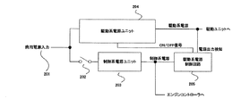
次に本実施例の電源構成を示すブロック図について、図2を用いて説明する。 Next, a block diagram showing the power supply configuration of this embodiment will be described with reference to FIG.
201は本体101が接続される商用電源であり、この商用電源201から電源スイッチ202を介して制御系電源ユニット203へ、また、商用電源201から直接駆動系電源ユニット204へ接続されている。
制御系電源ユニット203は、エンジンコントローラ126およびビデオコントローラ127、さらに、駆動系電源制御回路205に電力を供給している。駆動系電源制御回路205は、駆動系電源ユニット204のON/OFFを制御すると共に駆動系電源ユニット204の出力電圧をモニタしている。
The control system
本実施例では、この駆動系電源制御回路205が独立している場合を示しているが、エンジンコントローラ126内部に含まれる場合もあるし、制御系電源ユニット203に内包される場合もあり、多種の形態が考えられる。また、実施例では駆動系電源ユニット204のON/OFF信号は、駆動系電源ユニット204内部のコントロール端子を直接制御しているが、別途駆動系電源ユニット204の商用電源入力側にリレー等のスイッチ手段を設け、これらスイッチ手段をON/OFF制御する事により代用する場合もある。
In this embodiment, the case where the drive system power
駆動系電源ユニット204は、図1に示す、モーターやソレノイドなどのアクチュエータ類、プロセスカートリッジ108に所定の電圧を供給する高圧電源、また不図示の外部オプション、たとえば記録紙を大量にストックする大容量給紙装置や記録後の用紙をステープルするステープル装置や記録後の用紙を分類して排紙する多ビン排紙装置などへ電力を供給している。
The drive system
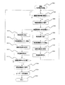
次に図3のフローチャートを用いて各電源ユニットの動作について説明する。 Next, the operation of each power supply unit will be described with reference to the flowchart of FIG.
まず、ユーザーによって本体101の電源スイッチ202がONされる(S101)と、制御系電源ユニット203が立ち上がり(S102)、駆動系電源制御回路205およびエンジンコントローラ126、ビデオコントローラ127に各々電力を供給し始める。
First, when the
駆動系電源制御回路205は、エンジンコントローラ126の指示を受け(S103)、駆動系電源ユニット204へON信号を送る(S104)。
The drive system power
駆動系電源ユニット204は、駆動系電源制御回路205からのON信号を受けて起動を開始し、駆動系ユニットへの電力供給を開始する。ここで、駆動系電源制御回路205は、駆動系電源ユニット204へON信号を送った後、所定時間後、すなわち駆動系電源ユニット204が立ち上がるのに十分な時間を経た後に(S105)、駆動系電源ユニット204の出力電圧が正常な値を示しているかを確認する(S106)。もし正常に起動していれば、スタンバイ状態となり、ビデオコントローラ127からのプリント動作指示に備える(S107)。
The drive system
もし駆動系電源ユニット204が正常な電圧値を出力していなければ(S106)、起動失敗と判断し、即時に駆動系電源制御回路205から駆動系電源ユニット204へOFF信号を送る(S108)。そして所定時間、すなわち駆動系電源ユニット204のシャットダウンが解除されるのに十分な時間以上の後(S112)、駆動系電源制御回路205は再び駆動系電源ユニットへON信号を送り(S104)、上述の手順を繰り返す。
If the drive system
また、この時駆動系電源制御回路205は、駆動系電源ユニット204の再起動を行った回数をカウントしており、駆動系電源ユニット204の再起動失敗と判断した場合(S106)、駆動系電源ユニット204へOFF信号を送る(S108)と共に、再起動の回数が予め設定された所定の回数に達したかどうかを判断する(S109)。
At this time, the drive system power
ここで再起動回数が所定の回数以下の場合は、上述の通り再起動のシーケンスに戻るが、もし再起動回数が所定の回数に達した場合は、商用電源電圧201や駆動系電源ユニット204に何らかの異常が生じていると判断し、即時に異常をユーザーに報知する(S110)。
If the number of restarts is less than or equal to the predetermined number, the process returns to the restart sequence as described above. However, if the number of restarts reaches the predetermined number, the commercial
なお、上記実施例では、所定回数以上再起動が不能であった場合にのみ、異常が発生した事をユーザーに報知する構成となっているが、当然ながら、起動に失敗した段階から、再起動待ち、再起動中など、逐次ユーザーにシステムの状態を報知する構成にする事も可能である。 In the above-described embodiment, the configuration is such that the user is informed that an abnormality has occurred only when the restart is impossible for a predetermined number of times or more. It is also possible to adopt a configuration in which the system status is sequentially notified to the user, such as waiting or restarting.
上記のように、駆動系電源ユニット204が何らかの不具合、例えば商用電源電圧201の一時的な異常や駆動系電源ユニット204の異常、または駆動系電源ユニット204が電力を供給する負荷側の異常、例えばユーザー誤操作などによってショートを引き起こしてしまった場合等を監視し、異常が起こり起動失敗に至った場合は、駆動系電源ユニットの再起動を行って起動を確実なものにすると共に、不可避の異常が生じている場合には駆動系電源ユニット204を停止させ、ユーザーに知らせる事が出来る。
As described above, the drive system
以上、本実施例によれば、商用電源電圧201の変動やユーザーの誤操作による駆動系電源ユニットのシャットダウンが生じた場合においても、駆動系電源を再起動し、ユーザーに混乱を招いたりユーザーの手を煩わせることなく自動的に復帰させる事が可能である。
As described above, according to the present embodiment, even when the drive system power supply unit shuts down due to fluctuations in the commercial
次に図を用いて、本発明の実施例2について説明する。主な構成および動作は、本発明の実施例1にて説明した通りであるので、省略する。 Next, Embodiment 2 of the present invention will be described with reference to the drawings. Since the main configuration and operation are the same as those described in the first embodiment of the present invention, they are omitted.
図4のフローチャートを用いて各電源ユニットの動作について説明する。 The operation of each power supply unit will be described with reference to the flowchart of FIG.
本実施例では、既に制御系電源ユニット203および駆動系電源ユニット204が正常に起動し、動作している状態から開始する(S201)。
In the present embodiment, the control system
駆動系電源制御回路205は常に駆動系電源ユニット204の出力電圧が正常な値を示しているかを確認している(S202)。もしこの時に駆動系電源ユニット204が出力する電圧値にシャットダウン等の異常が見られた場合、駆動系電源制御回路205が即時に駆動系電源ユニット204へOFF信号を送る(S203)。
The drive system power
その後所定時間T1の間、すなわち駆動系電源ユニット204のシャットダウンが解除されるのに十分な時間以上待った後(S205)、駆動系電源制御回路205は駆動系電源ユニット204の再起動の時間間隔を計測するタイマーをスタートする(S206)。また同時に、駆動系電源制御回路205が駆動系電源ユニット204へON信号を送信する(S207)。
Thereafter, after waiting for a predetermined time T1, that is, a time sufficient for releasing the shutdown of the drive system power supply unit 204 (S205), the drive system power
駆動系電源制御回路205は、再起動待ち後、すなわち駆動系電源ユニット204が立ち上がるのに十分な時間を経た後に(S208)再び駆動系電源ユニット204の出力電圧を監視するシーケンスに戻る(S202)。
The drive system power
ここでもし、再び駆動電源ユニット204が出力する電圧値にシャットダウン等、正常に立ち上がっていない状態が見られた場合(S202)、駆動系電源制御回路205が即時に駆動系電源ユニット204へOFF信号を送る(S203)。この時駆動系電源制御回路205は、再起動の時間間隔を計測するタイマーの時間を確認し、この時の時間間隔が所定時間より短かった場合(例えば数秒〜数分の間で設定される)(S204)、駆動系電源制御回路205は、今度は再起動までの所定時間T2の間待つ(S209)。
Here, if the voltage value output from the drive
所定時間T1と所定時間T2の長短関係は通常、
T1 < T2
となっており、再起動間隔が所定の時間より短い場合は、再起動するまでの時間を増やす事になる。これは、たとえば時間帯に応じて外部の影響を受けて商用電源電圧201が不安定になる状態が続いた場合、再起動までの待機時間を増やす事でこの時間帯を大きく外す事が可能となる。
The long-short relationship between the predetermined time T1 and the predetermined time T2 is usually
T1 <T2
If the restart interval is shorter than the predetermined time, the time until restart is increased. This is because, for example, when the commercial
所定時間T2の後、再び駆動系電源制御回路205は駆動系電源ユニット204の再起動の時間間隔を計測するタイマーを再スタートする(S210)と共に、再び、駆動系電源制御回路205は駆動系電源ユニット204へON信号を送信する(S211)。
After the predetermined time T2, the drive system power
駆動系電源制御回路205は、再起動待ち後、すなわち駆動系電源ユニット204が立ち上がるのに十分な時間を経た後に(S212)再び駆動系電源ユニット204の出力電圧を確認し(S213)、出力電圧が正常であれば、再び出力電圧を監視するシーケンスに戻る(S202)。
The drive system power
もしこの時に、再度駆動系電源ユニット204の出力電圧が正常な値になっていない場合には(S213)、駆動系電源制御回路205は駆動系電源ユニット204へOFF信号を送って(S214)駆動系電源ユニット204を停止させると共に、異常が発生している事をユーザーに報知する(S215)。
If the output voltage of the drive system
なお、上記実施例では、再起動が不能であった場合にのみをユーザーに報知する構成となっているが、当然ながら、動作中に駆動系電源ユニット204が停止した段階から、再起動待ち、再起動中など、逐次ユーザーにシステムの状態を報知する構成にする事も可能である。
In the above-described embodiment, it is configured to notify the user only when the restart is impossible, but of course, from the stage where the drive system
また、上記実施例では、再起動の時間間隔に応じて再起動までの時間を二段階で変えているが、さらに再起動までの時間を多段階に分けて、段階的に再起動までの時間を変えても良いし、再起動の時間間隔に応じて、無段階に再起動までの時間を変えても良い。更に、第一の実施例と組み合わせて、再起動の回数も同時に計数し、所定の回数に達したところで再起動動作を停止するような構成にする事も可能である。 In the above embodiment, the time to restart is changed in two stages according to the restart time interval, but the time to restart is further divided into multiple stages and the time to restart in stages. Or may be changed steplessly in accordance with the restart time interval. Further, in combination with the first embodiment, the number of restarts can be counted simultaneously, and the restart operation can be stopped when the predetermined number of times is reached.
上記のように、駆動系電源ユニット204が何らかの不具合、例えば商用電源電圧201の一時的な異常や駆動系電源ユニット204の異常、または駆動系電源ユニット204が電力を供給する負荷側の異常、例えばユーザー誤操作などによってショートを引き起こしてしまった場合等を監視し、異常が起こり、動作中に駆動系電源ユニット停止に至った場合は、駆動系電源ユニットの再起動を行って起動を確実なものにすると共に、不可避の異常が生じている場合には駆動系電源ユニット204を停止させ、ユーザーに知らせる事が出来る。
As described above, the drive system
以上、本実施例によれば、商用電源電圧201の変動やユーザーの誤操作による駆動系電源ユニットのシャットダウンが生じた場合においても、駆動系電源を再起動し、ユーザーに混乱を招いたり、ユーザーの手を煩わせることなく自動的に復帰させる事が可能である。
As described above, according to the present embodiment, even when the drive system power supply unit shuts down due to fluctuations in the commercial
101 画像形成装置
201 商用電源入力
203 制御系電源ユニット
204 駆動系電源ユニット
205 駆動系電源制御回路(電源制御手段および電圧検知手段に対応)
101
Claims (9)
前記駆動系ユニットの動作を制御するコントローラと、を有する画像形成装置の電源システムであって、
商用電源と接続され、前記駆動系ユニットに電力を供給する駆動系電源ユニットと、
前記商用電源と接続され、前記コントローラに電力を供給する制御系電源ユニットと、
前記駆動系電源ユニットのON/OFFを制御するとともに前記駆動系電源ユニットの出力電圧をモニタする駆動系電源制御回路と、を有し、
前記制御系電源ユニットは、前記駆動系電源制御回路を動作させるために前記駆動系電源制御回路にも電力を供給し、
前記駆動系電源制御回路は、前記駆動系電源ユニットの出力電圧が正常な値でない場合、前記駆動系電源ユニットをOFFし、前記商用電源の変動や誤操作による前記駆動系電源ユニットのシャットダウンが解除されるに十分な待機時間の経過後、前記駆動系電源ユニットをONすることにより、前記駆動系電源ユニットを再起動することを特徴とする電源システム。 A drive system unit for forming an image on recording paper;
A controller for controlling the operation of the drive system unit, and a power supply system for an image forming apparatus,
A drive system power supply unit connected to a commercial power supply and supplying power to the drive system unit;
A control system power supply unit connected to the commercial power supply and supplying power to the controller;
A drive system power supply control circuit that controls ON / OFF of the drive system power supply unit and monitors the output voltage of the drive system power supply unit;
The control system power supply unit supplies power to the drive system power supply control circuit in order to operate the drive system power supply control circuit,
When the output voltage of the drive system power supply unit is not a normal value, the drive system power supply control circuit turns off the drive system power supply unit, and the shutdown of the drive system power supply unit due to the fluctuation or erroneous operation of the commercial power supply is released. A power supply system characterized by restarting the drive system power supply unit by turning on the drive system power supply unit after a sufficient standby time has elapsed.
前記制御系電源ユニットは、前記駆動系電源制御回路を動作させるために前記駆動系電源制御回路にも電力を供給し、
前記駆動系電源制御回路は、前記駆動系電源ユニットの出力電圧が正常な値でない場合、前記駆動系電源ユニットをOFFし、前記商用電源の変動や誤操作による前記駆動系電源ユニットのシャットダウンが解除されるに十分な待機時間の経過後、前記駆動系電源ユニットをONすることにより、前記駆動系電源ユニットを再起動することを特徴とする電源システムの制御方法。 Connected to a commercial power supply to supply power to the drive system unit for forming an image on recording paper, and supplied to the controller connected to the commercial power supply and controlling the operation of the drive system unit A control system power supply unit for controlling the ON / OFF of the drive system power supply unit and a drive system power supply control circuit for monitoring an output voltage of the drive system power supply unit. ,
The control system power supply unit supplies power to the drive system power supply control circuit in order to operate the drive system power supply control circuit,
When the output voltage of the drive system power supply unit is not a normal value, the drive system power supply control circuit turns off the drive system power supply unit, and the shutdown of the drive system power supply unit due to the fluctuation or erroneous operation of the commercial power supply is released. A control method for a power supply system, wherein the drive system power supply unit is restarted by turning on the drive system power supply unit after a sufficient standby time has elapsed.
Priority Applications (1)
| Application Number | Priority Date | Filing Date | Title |
|---|---|---|---|
| JP2004258497A JP4307351B2 (en) | 2004-09-06 | 2004-09-06 | Power supply system and control method thereof |
Applications Claiming Priority (1)
| Application Number | Priority Date | Filing Date | Title |
|---|---|---|---|
| JP2004258497A JP4307351B2 (en) | 2004-09-06 | 2004-09-06 | Power supply system and control method thereof |
Publications (3)
| Publication Number | Publication Date |
|---|---|
| JP2006074968A JP2006074968A (en) | 2006-03-16 |
| JP2006074968A5 JP2006074968A5 (en) | 2008-08-14 |
| JP4307351B2 true JP4307351B2 (en) | 2009-08-05 |
Family
ID=36154955
Family Applications (1)
| Application Number | Title | Priority Date | Filing Date |
|---|---|---|---|
| JP2004258497A Active JP4307351B2 (en) | 2004-09-06 | 2004-09-06 | Power supply system and control method thereof |
Country Status (1)
| Country | Link |
|---|---|
| JP (1) | JP4307351B2 (en) |
Families Citing this family (3)
| Publication number | Priority date | Publication date | Assignee | Title |
|---|---|---|---|---|
| JP4509138B2 (en) * | 2007-05-01 | 2010-07-21 | シャープ株式会社 | Image forming apparatus and image forming method |
| JP5839828B2 (en) * | 2011-04-25 | 2016-01-06 | キヤノン株式会社 | Image forming apparatus, image forming apparatus control method, and program |
| JP6597417B2 (en) * | 2016-03-09 | 2019-10-30 | 株式会社リコー | Electronic device, recovery method and program |
-
2004
- 2004-09-06 JP JP2004258497A patent/JP4307351B2/en active Active
Also Published As
| Publication number | Publication date |
|---|---|
| JP2006074968A (en) | 2006-03-16 |
Similar Documents
| Publication | Publication Date | Title |
|---|---|---|
| US8843017B2 (en) | Image forming apparatus including dehumidification heater and control method for image forming apparatus including dehumidification heater | |
| JP2010014864A (en) | Heating device and image forming apparatus | |
| JP4836239B2 (en) | Power supply device and image forming apparatus | |
| JP2008003469A (en) | Heating device and image forming apparatus | |
| JP2006129651A (en) | Power supply, system equipment, electronic equipment, and power supply control method | |
| JP6108796B2 (en) | Printing apparatus, reading apparatus, control method thereof, and program | |
| JP2009300944A (en) | Heating unit and image forming apparatus | |
| JP4307351B2 (en) | Power supply system and control method thereof | |
| JP6106623B2 (en) | Image forming apparatus | |
| JP2006073023A (en) | Power saving control device | |
| JP2006204034A (en) | Power supply system and image forming apparatus | |
| JP2010083064A (en) | Image forming apparatus | |
| JP2010026037A (en) | Image forming apparatus | |
| US6744993B2 (en) | Sheet winding detecting device and image forming apparatus | |
| JPH10268713A (en) | Automatic power-off circuit | |
| JP4508566B2 (en) | Image forming apparatus | |
| JP2006113117A (en) | Image forming apparatus | |
| JP2020079855A (en) | Image forming apparatus and method for controlling image forming apparatus | |
| JP2004248478A (en) | Electric driving equipment | |
| JP2009145748A (en) | Image forming apparatus | |
| JP5752895B2 (en) | Image forming apparatus | |
| JP2006125296A (en) | Method for controlling fan and device for actuating control unit | |
| JP2005165143A (en) | Image forming apparatus | |
| JP2005148669A (en) | Image forming apparatus | |
| JPH06289669A (en) | Image forming device |
Legal Events
| Date | Code | Title | Description |
|---|---|---|---|
| A521 | Written amendment |
Free format text: JAPANESE INTERMEDIATE CODE: A523 Effective date: 20070803 |
|
| A621 | Written request for application examination |
Free format text: JAPANESE INTERMEDIATE CODE: A621 Effective date: 20070803 |
|
| A521 | Written amendment |
Free format text: JAPANESE INTERMEDIATE CODE: A523 Effective date: 20080627 |
|
| A977 | Report on retrieval |
Free format text: JAPANESE INTERMEDIATE CODE: A971007 Effective date: 20080821 |
|
| A131 | Notification of reasons for refusal |
Free format text: JAPANESE INTERMEDIATE CODE: A131 Effective date: 20080902 |
|
| A521 | Written amendment |
Free format text: JAPANESE INTERMEDIATE CODE: A523 Effective date: 20081021 |
|
| A131 | Notification of reasons for refusal |
Free format text: JAPANESE INTERMEDIATE CODE: A131 Effective date: 20081216 |
|
| A521 | Written amendment |
Free format text: JAPANESE INTERMEDIATE CODE: A523 Effective date: 20081222 |
|
| TRDD | Decision of grant or rejection written | ||
| A01 | Written decision to grant a patent or to grant a registration (utility model) |
Free format text: JAPANESE INTERMEDIATE CODE: A01 Effective date: 20090421 |
|
| A01 | Written decision to grant a patent or to grant a registration (utility model) |
Free format text: JAPANESE INTERMEDIATE CODE: A01 |
|
| A61 | First payment of annual fees (during grant procedure) |
Free format text: JAPANESE INTERMEDIATE CODE: A61 Effective date: 20090428 |
|
| R150 | Certificate of patent or registration of utility model |
Ref document number: 4307351 Country of ref document: JP Free format text: JAPANESE INTERMEDIATE CODE: R150 Free format text: JAPANESE INTERMEDIATE CODE: R150 |
|
| FPAY | Renewal fee payment (event date is renewal date of database) |
Free format text: PAYMENT UNTIL: 20120515 Year of fee payment: 3 |
|
| FPAY | Renewal fee payment (event date is renewal date of database) |
Free format text: PAYMENT UNTIL: 20120515 Year of fee payment: 3 |
|
| FPAY | Renewal fee payment (event date is renewal date of database) |
Free format text: PAYMENT UNTIL: 20130515 Year of fee payment: 4 |
|
| FPAY | Renewal fee payment (event date is renewal date of database) |
Free format text: PAYMENT UNTIL: 20140515 Year of fee payment: 5 |