JP4305903B2 - Image generation system, program, and information storage medium - Google Patents
Image generation system, program, and information storage medium Download PDFInfo
- Publication number
- JP4305903B2 JP4305903B2 JP2003272958A JP2003272958A JP4305903B2 JP 4305903 B2 JP4305903 B2 JP 4305903B2 JP 2003272958 A JP2003272958 A JP 2003272958A JP 2003272958 A JP2003272958 A JP 2003272958A JP 4305903 B2 JP4305903 B2 JP 4305903B2
- Authority
- JP
- Japan
- Prior art keywords
- texture
- texel value
- value pattern
- normal vector
- image
- Prior art date
- Legal status (The legal status is an assumption and is not a legal conclusion. Google has not performed a legal analysis and makes no representation as to the accuracy of the status listed.)
- Expired - Fee Related
Links
- 238000013507 mapping Methods 0.000 claims description 70
- 239000013598 vector Substances 0.000 claims description 70
- 230000015572 biosynthetic process Effects 0.000 claims description 15
- 238000003786 synthesis reaction Methods 0.000 claims description 15
- 230000007423 decrease Effects 0.000 claims description 11
- 238000012545 processing Methods 0.000 description 67
- 238000000034 method Methods 0.000 description 56
- 230000008569 process Effects 0.000 description 34
- 230000033001 locomotion Effects 0.000 description 22
- 230000006870 function Effects 0.000 description 18
- 238000004364 calculation method Methods 0.000 description 13
- 210000000988 bone and bone Anatomy 0.000 description 12
- 238000004891 communication Methods 0.000 description 10
- 230000008034 disappearance Effects 0.000 description 10
- 230000000694 effects Effects 0.000 description 8
- 230000009466 transformation Effects 0.000 description 7
- 238000006243 chemical reaction Methods 0.000 description 5
- 238000002156 mixing Methods 0.000 description 5
- 238000004088 simulation Methods 0.000 description 4
- 230000000052 comparative effect Effects 0.000 description 3
- 230000001419 dependent effect Effects 0.000 description 3
- 239000011159 matrix material Substances 0.000 description 3
- 238000012546 transfer Methods 0.000 description 3
- 238000010586 diagram Methods 0.000 description 2
- 238000001914 filtration Methods 0.000 description 2
- 238000004519 manufacturing process Methods 0.000 description 2
- 230000001133 acceleration Effects 0.000 description 1
- 230000009471 action Effects 0.000 description 1
- 230000008901 benefit Effects 0.000 description 1
- 230000008033 biological extinction Effects 0.000 description 1
- 230000005540 biological transmission Effects 0.000 description 1
- 238000004422 calculation algorithm Methods 0.000 description 1
- 239000000470 constituent Substances 0.000 description 1
- 238000007796 conventional method Methods 0.000 description 1
- 230000006837 decompression Effects 0.000 description 1
- 238000005259 measurement Methods 0.000 description 1
- 238000012986 modification Methods 0.000 description 1
- 230000004048 modification Effects 0.000 description 1
- 238000010606 normalization Methods 0.000 description 1
- 230000003287 optical effect Effects 0.000 description 1
- 230000002093 peripheral effect Effects 0.000 description 1
- 238000009877 rendering Methods 0.000 description 1
- 230000000007 visual effect Effects 0.000 description 1
Images


Landscapes
- Processing Or Creating Images (AREA)
- Image Generation (AREA)
Description
本発明は、画像生成システム、プログラム及び情報記憶媒体に関する。 The present invention relates to an image generation system, a program, and an information storage medium.
従来より、キャラクタなどのオブジェクトが配置設定されるオブジェクト空間内(仮想的な3次元空間)において仮想カメラ(所与の視点)から見える画像を生成する画像生成システム(ゲームシステム)が知られており、いわゆる仮想現実を体験できるものとして人気が高い。 Conventionally, an image generation system (game system) that generates an image that can be viewed from a virtual camera (a given viewpoint) in an object space (virtual three-dimensional space) in which an object such as a character is set is known. It is popular as a place to experience so-called virtual reality.
しかしながら、このような画像生成システムで生成されたゲーム画像では、ポリゴンにより構成されたオブジェクトの輪郭線が、オブジェクトの形状やオブジェクトを見る方向などに依存せず、常に一定の太さになる。このため、今一つプレーヤの情感に訴えることができないという問題がある。そこで、このような輪郭線の強弱の表現を実現するものとして次の従来技術が知られている。
しかしながら、この従来技術では、仮想カメラの視線方向とオブジェクトの面の法線ベクトルとの内積を求める処理などが必要になるため、処理負荷が重いという課題がある。 However, this conventional technique has a problem that the processing load is heavy because a process for obtaining the inner product of the viewing direction of the virtual camera and the normal vector of the object surface is required.
本発明は、以上のような課題に鑑みてなされたものであり、その目的とするところは、少ない処理負荷で輪郭強調や輪郭ぼかしなどの画像表現を実現できる画像生成システム、プログラム及び情報記憶媒体を提供することにある。 The present invention has been made in view of the above problems, and an object of the present invention is to provide an image generation system, a program, and an information storage medium capable of realizing image expression such as contour enhancement and contour blurring with a small processing load. Is to provide.
本発明は、オブジェクト空間において仮想カメラから見える画像を生成する画像生成システムであって、テクスチャを記憶するテクスチャ記憶部と、カメラ座標系又はスクリーン座標系でのオブジェクトの面の法線ベクトルの座標成分を求め、求められた座標成分に基づいてテクスチャ座標を求めるテクスチャ座標演算部と、求められたテクスチャ座標に基づいて、所与のテクセル値パターンを有するテクスチャをオブジェクトにマッピングするテクスチャマッピング部とを含み、前記テクスチャマッピング部が、仮想カメラの視線方向とオブジェクトの法線ベクトル方向が平行である場合のテクスチャ座標の指定位置であるテクスチャの円中心から、前記視線方向と前記法線ベクトル方向が直交する場合のテクスチャ座標の指定位置であるテクスチャの円外周に向かうにつれて、テクセル値が単調増加又は単調減少するテクセル値パターンを有するテクスチャを、オブジェクトにマッピングする画像生成システムに関係する。また本発明は、上記各部としてコンピュータを機能させるプログラムに関係する。また本発明は、コンピュータ読み取り可能な情報記憶媒体であって、上記各部としてコンピュータを機能させるプログラムを記憶(記録)した情報記憶媒体に関係する。 The present invention is an image generation system for generating an image that can be viewed from a virtual camera in an object space, and a texture storage unit that stores texture, and a coordinate component of a normal vector of an object surface in a camera coordinate system or a screen coordinate system A texture coordinate calculation unit that obtains texture coordinates based on the obtained coordinate components, and a texture mapping unit that maps a texture having a given texel value pattern to an object based on the obtained texture coordinates. In the texture mapping unit, the line-of-sight direction and the normal vector direction are orthogonal to each other from the center of the texture circle, which is the designated position of the texture coordinates when the line-of-sight direction of the virtual camera and the normal vector direction of the object are parallel Is the specified position of the texture coordinate Toward the circular outer periphery of Kusucha, textures having a texel value pattern texel value decreases monotonically increases or relates to an image generation system that maps to the object. The present invention also relates to a program that causes a computer to function as each of the above-described units. The present invention also relates to a computer-readable information storage medium that stores (records) a program that causes a computer to function as each unit.
本発明によれば、カメラ座標系又はスクリーン座標系でのオブジェクトの面の法線ベクトルの座標成分が求められ、この座標成分に基づいてテクスチャ座標が求められる。そして円中心から円外周に向かうにつれてテクセル値が単調増加又は単調減少するテクセル値パターン(グラディエーションパターン)を有するテクスチャが、求められたテクスチャ座標に基づいてオブジェクトにマッピングされる。このようにすれば、テクスチャマッピングを行うだけという少ない処理負荷で、種々の画像表現を実現できるようになる。 According to the present invention, the coordinate component of the normal vector of the surface of the object in the camera coordinate system or the screen coordinate system is obtained, and the texture coordinate is obtained based on this coordinate component. Then, a texture having a texel value pattern (gradation pattern) in which the texel value monotonously increases or monotonously decreases from the center of the circle toward the outer periphery of the circle is mapped to the object based on the obtained texture coordinates. In this way, various image representations can be realized with a small processing load of only performing texture mapping.
また本発明に係る画像生成システム、プログラム及び情報記憶媒体では、前記テクセル値パターンを有するテクスチャをオブジェクトにマッピングすることで、オブジェクトの輪郭強調画像又は輪郭ぼかし画像を生成するようにしてもよい。 In the image generation system, the program, and the information storage medium according to the present invention, the contour-enhanced image or the contour-blurred image of the object may be generated by mapping the texture having the texel value pattern to the object.
また本発明に係る画像生成システム、プログラム及び情報記憶媒体では、テクスチャの前記テクセル値がα値を含み、オブジェクトの画像と背景の画像とを、テクスチャの前記α値に基づいて合成するα合成部を含むようにしてもよい(α合成部としてコンピュータを機能させる、或いはα合成部としてコンピュータを機能させるプログラムを記憶するようにしてもよい)。 In the image generation system, the program, and the information storage medium according to the present invention, the texel value of the texture includes an α value, and an α composition unit that synthesizes an object image and a background image based on the texture α value. (A program that causes a computer to function as the α synthesis unit or a program that causes the computer to function as the α synthesis unit may be stored).
また本発明に係る画像生成システム、プログラム及び情報記憶媒体では、前記テクスチャマッピング部が、オブジェクトの中心部分からオブジェクトの輪郭部分に向かって時間経過に伴いオブジェクトが徐々に透明になるように、或いは、オブジェクトの輪郭部分からオブジェクトの中心部分に向かって時間経過に伴いオブジェクトが徐々に透明になるように、オブジェクトの消滅時にテクセル値パターンが時間経過に伴い変化するテクスチャをオブジェクトにマッピングするようにしてもよい。 In the image generation system, the program, and the information storage medium according to the present invention, the texture mapping unit may be configured so that the object gradually becomes transparent with time from the center part of the object toward the contour part of the object, or The texture whose texel value pattern changes with the passage of time when the object disappears may be mapped to the object so that the object gradually becomes transparent with the passage of time from the contour of the object toward the center of the object. Good.
このようにすれば、テクスチャマッピングを行うだけという少ない処理負荷で、演出効果の高いオブジェクトの消滅表示を実現できる。 In this way, it is possible to realize disappearance display of an object having a high effect with a small processing load of just performing texture mapping.
また本発明に係る画像生成システム、プログラム及び情報記憶媒体では、前記テクスチャマッピング部が、オブジェクトの中心部分からオブジェクトの輪郭部分に向かって時間経過に伴いオブジェクトが徐々に不透明になるように、或いは、オブジェクトの輪郭部分からオブジェクトの中心部分に向かって時間経過に伴いオブジェクトが徐々に不透明になるように、オブジェクトの出現時にテクセル値パターンが時間経過に伴い変化するテクスチャをオブジェクトにマッピングするようにしてもよい。 In the image generation system, the program, and the information storage medium according to the present invention, the texture mapping unit may be configured so that the object becomes gradually opaque with time from the center portion of the object toward the contour portion of the object, or A texture whose texel value pattern changes with the passage of time at the appearance of the object may be mapped to the object so that the object gradually becomes opaque with the passage of time from the contour portion of the object toward the center portion of the object. Good.
このようにすれば、テクスチャマッピングを行うだけという少ない処理負荷で、演出効果の高いオブジェクトの出現表示を実現できる。 In this way, it is possible to realize the appearance display of an object having a high effect with a small processing load of just performing texture mapping.
また本発明に係る画像生成システム、プログラム及び情報記憶媒体では、前記テクスチャマッピング部が、オブジェクトについてのゲームイベントが発生した場合に、発生したゲームイベントに応じたテクセル値パターンのテクスチャをオブジェクトにマッピングするようにしてもよい。 In the image generation system, program, and information storage medium according to the present invention, when the game event for the object occurs, the texture mapping unit maps the texture of the texel value pattern corresponding to the generated game event to the object. You may do it.
また本発明は、オブジェクト空間において仮想カメラから見える画像を生成する画像生成システムであって、テクスチャを記憶するテクスチャ記憶部と、カメラ座標系又はスクリーン座標系でのオブジェクトの面の法線ベクトルの座標成分を求め、求められた座標成分に基づいてテクスチャ座標を求めるテクスチャ座標演算部と、求められたテクスチャ座標に基づいて、所与のテクセル値パターンを有するテクスチャをオブジェクトにマッピングするテクスチャマッピング部とを含み、前記テクスチャマッピング部が、オブジェクトについてのゲームイベントが発生した場合に、発生したゲームイベントに応じたテクセル値パターンのテクスチャをオブジェクトにマッピングする画像生成システムに関係する。また本発明は、上記各部としてコンピュータを機能させるプログラムに関係する。また本発明は、コンピュータ読み取り可能な情報記憶媒体であって、上記各部としてコンピュータを機能させるプログラムを記憶(記録)した情報記憶媒体に関係する。 The present invention also relates to an image generation system for generating an image that can be viewed from a virtual camera in an object space, and a texture storage unit that stores textures and coordinates of normal vectors of an object surface in a camera coordinate system or a screen coordinate system. A texture coordinate calculation unit that obtains a component and obtains a texture coordinate based on the obtained coordinate component, and a texture mapping unit that maps a texture having a given texel value pattern to an object based on the obtained texture coordinate And the texture mapping unit relates to an image generation system for mapping a texture of a texel value pattern corresponding to the generated game event to the object when a game event for the object occurs. The present invention also relates to a program that causes a computer to function as each of the above-described units. The present invention also relates to a computer-readable information storage medium that stores (records) a program that causes a computer to function as each unit.
本発明によれば、カメラ座標系又はスクリーン座標系でのオブジェクトの面の法線ベクトルの座標成分が求められ、この座標成分に基づいてテクスチャ座標が求められる。そしてゲームイベントが発生した場合に、そのゲームイベントに応じたテクセル値パターンのテクスチャがオブジェクトにマッピングされる。例えば第1のゲームイベントが発生した場合には、第1のゲームイベント用の第1のテクセル値パターンを有するテクスチャがオブジェクトにマッピングされ、第2のゲームイベントが発生した場合には、第2のゲームイベント用の第2のテクセル値パターンを有するテクスチャがオブジェクトにマッピングされる。また第3のゲームイベントが発生した場合には、時間経過に伴いテクセル値パターンが変化する第3のゲームイベント用のテクスチャがオブジェクトにマッピングされる。このようにすれば、テクスチャマッピングを行うだけという少ない処理負荷で、ゲームイベントに応じた多彩な画像表現を実現できる。 According to the present invention, the coordinate component of the normal vector of the surface of the object in the camera coordinate system or the screen coordinate system is obtained, and the texture coordinate is obtained based on this coordinate component. When a game event occurs, the texture of the texel value pattern corresponding to the game event is mapped to the object. For example, when the first game event occurs, the texture having the first texel value pattern for the first game event is mapped to the object, and when the second game event occurs, the second A texture having a second texel value pattern for a game event is mapped to the object. When the third game event occurs, the texture for the third game event in which the texel value pattern changes with the passage of time is mapped to the object. In this way, it is possible to realize various image representations according to the game event with a small processing load of just performing texture mapping.
また本発明に係る画像生成システム、プログラム及び情報記憶媒体では、前記ゲームイベントが、オブジェクトに対して他のオブジェクトがヒットするイベントであり、前記テクスチャマッピング部が、他のオブジェクトがオブジェクトにヒットした場合に、オブジェクトのヒット部位に応じたテクセル値パターンのテクスチャをオブジェクトにマッピングするようにしてもよい。 In the image generation system, the program, and the information storage medium according to the present invention, the game event is an event where another object hits the object, and the texture mapping unit hits the object. In addition, the texture of the texel value pattern corresponding to the hit part of the object may be mapped to the object.
また本発明に係る画像生成システム、プログラム及び情報記憶媒体では、前記ゲームイベントが、オブジェクトに対して他のオブジェクトの攻撃がヒットするイベントであり、前記テクスチャマッピング部が、他のオブジェクトの攻撃がオブジェクトにヒットした場合に、他のオブジェクトの攻撃の種類に応じたテクセル値パターンのテクスチャをオブジェクトにマッピングするようにしてもよい。 In the image generation system, the program, and the information storage medium according to the present invention, the game event is an event in which an attack of another object hits the object, and the texture mapping unit detects that the attack of the other object is an object. When a hit is made, a texture having a texel value pattern corresponding to the type of attack of another object may be mapped to the object.
また本発明に係る画像生成システム、プログラム及び情報記憶媒体では、前記ゲームイベントが、オブジェクトが消滅又は出現するイベントであり、前記テクスチャマッピング部が、オブジェクトの消滅時又は出現時に、テクセル値パターンが時間経過に伴い変化するテクスチャをオブジェクトにマッピングするようにしてもよい。 In the image generation system, the program, and the information storage medium according to the present invention, the game event is an event in which an object disappears or appears, and the texture mapping unit has a texel value pattern in time when the object disappears or appears. You may make it map the texture which changes with progress to an object.
以下、本実施形態について説明する。 Hereinafter, this embodiment will be described.
なお、以下に説明する本実施形態は、特許請求の範囲に記載された本発明の内容を不当に限定するものではない。また本実施形態で説明される構成の全てが、本発明の必須構成要件であるとは限らない。 In addition, this embodiment demonstrated below does not unduly limit the content of this invention described in the claim. In addition, all the configurations described in the present embodiment are not necessarily essential configuration requirements of the present invention.
1.構成
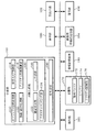
図1に本実施形態の画像生成システム(ゲームシステム)の機能ブロック図の例を示す。なお、本実施形態の画像生成システムは、図1の構成要素(各部)の一部を省略した構成としてもよい。
1. Configuration FIG. 1 shows an example of a functional block diagram of an image generation system (game system) of the present embodiment. Note that the image generation system of this embodiment may have a configuration in which some of the components (each unit) in FIG. 1 are omitted.
操作部160は、プレーヤが操作データを入力するためのものであり、その機能は、レバー、ボタン、ステアリング、マイク、タッチパネル型ディスプレイ、或いは筺体などにより実現できる。
The
記憶部170は、処理部100や通信部196などのワーク領域となるもので、その機能はRAMなどにより実現できる。
The
情報記憶媒体180(コンピュータにより読み取り可能な媒体)は、プログラムやデータなどを格納するものであり、その機能は、光ディスク(CD、DVD)、光磁気ディスク(MO)、磁気ディスク、ハードディスク、磁気テープ、或いはメモリ(ROM)などにより実現できる。処理部100は、情報記憶媒体180に格納されるプログラム(データ)に基づいて本実施形態の種々の処理を行う。即ち情報記憶媒体180には、本実施形態の各部としてコンピュータを機能させるためのプログラム(各部の処理をコンピュータに実行させるためのプログラム)が記憶(記録、格納)される。
The information storage medium 180 (computer-readable medium) stores programs, data, and the like, and functions as an optical disk (CD, DVD), magneto-optical disk (MO), magnetic disk, hard disk, and magnetic tape. Alternatively, it can be realized by a memory (ROM). The
表示部190は、本実施形態により生成された画像を出力するものであり、その機能は、CRT、LCD、タッチパネル型ディスプレイ、或いはHMD(ヘッドマウントディスプレイ)などにより実現できる。音出力部192は、本実施形態により生成された音を出力するものであり、その機能は、スピーカ、或いはヘッドフォンなどにより実現できる。
The
携帯型情報記憶装置194は、プレーヤの個人データやゲームのセーブデータなどが記憶されるものであり、この携帯型情報記憶装置194としては、メモリカードや携帯型ゲーム装置などがある。
The portable
通信部196は、外部(例えばホスト装置や他の画像生成システム)との間で通信を行うための各種の制御を行うものであり、その機能は、各種プロセッサ又は通信用ASICなどのハードウェアや、プログラムなどにより実現できる。
The
なお本実施形態の各部としてコンピュータを機能させるためのプログラム(データ)は、ホスト装置(サーバー)が有する情報記憶媒体からネットワーク及び通信部196を介して情報記憶媒体180(記憶部170)に配信するようにしてもよい。このようなホスト装置(サーバー)の情報記憶媒体の使用も本発明の範囲内に含めることができる。
Note that a program (data) for causing a computer to function as each unit of this embodiment is distributed from the information storage medium of the host device (server) to the information storage medium 180 (storage unit 170) via the network and the
処理部100(プロセッサ)は、操作部160からの操作データやプログラムなどに基づいて、ゲーム処理、画像生成処理、或いは音生成処理などの処理を行う。ここでゲーム処理としては、ゲーム開始条件が満たされた場合にゲームを開始する処理、ゲームを進行させる処理、キャラクタやマップなどのオブジェクトを配置する処理、オブジェクトを表示する処理、ゲーム結果を演算する処理、或いはゲーム終了条件が満たされた場合にゲームを終了する処理などがある。また処理部100は記憶部170をワーク領域として各種処理を行う。処理部100の機能は、各種プロセッサ(CPU、DSP等)やASIC(ゲートアレイ等)などのハードウェアや、プログラムにより実現できる。
The processing unit 100 (processor) performs processing such as game processing, image generation processing, or sound generation processing based on operation data and programs from the
処理部100は、オブジェクト空間設定部110、移動・動作処理部112、仮想カメラ制御部114、テクスチャ座標演算部116、画像生成部120、音生成部130を含む。なおこれらの一部を省略してもよい。
The
オブジェクト空間設定部110は、キャラクタ、樹木、車、柱、壁、建物、マップ(地形)などの表示物を表す各種オブジェクト(ポリゴン、自由曲面又はサブディビジョンサーフェスなどのプリミティブ面で構成されるオブジェクト)をオブジェクト空間に配置設定する処理を行う。即ちワールド座標系でのオブジェクトの位置や回転角度(向き、方向と同義)を決定し、その位置(X、Y、Z)にその回転角度(X、Y、Z軸回りでの回転角度)でオブジェクトを配置する。
The object
移動・動作処理部112は、オブジェクト(車、飛行機、又はキャラクタ等)の移動・動作演算(移動・動作シミュレーション)を行う。即ち、操作部160によりプレーヤが入力した操作データ、プログラム(移動・動作アルゴリズム)、或いは各種データ(モーションデータ)などに基づいて、オブジェクト(移動オブジェクト)をオブジェクト空間内で移動させたり、オブジェクトを動作(モーション、アニメーション)させる処理を行う。具体的には、オブジェクトの移動情報(位置、回転角度、速度、或いは加速度)や動作情報(各パーツオブジェクトの位置、或いは回転角度)を、1フレーム(1/60秒)毎に順次求めるシミュレーション処理を行う。ここでフレームは、オブジェクトの移動・動作処理(シミュレーション処理)や画像生成処理を行う時間の単位である。
The movement /
仮想カメラ制御部114は、オブジェクト空間内の所与(任意)の視点での画像を生成するための仮想カメラを制御する処理を行う。即ち、仮想カメラの位置(X、Y、Z)又は回転角度(X、Y、Z軸回りでの回転角度)を制御する処理(視点位置や視線方向を制御する処理)を行う。
The virtual
例えば仮想カメラによりオブジェクトを後方から撮影する場合には、オブジェクトの位置又は回転の変化に仮想カメラが追従するように、仮想カメラの位置又は回転角度(仮想カメラの向き)を制御する。この場合には、移動・動作処理部112で得られたオブジェクトの位置、回転角度又は速度などの情報に基づいて、仮想カメラを制御できる。或いは、仮想カメラを、予め決められた移動経路で移動させながら予め決められた回転角度で回転させるようにしてもよい。この場合には、仮想カメラの位置(移動経路)や回転角度を特定するための仮想カメラデータに基づいて仮想カメラを制御する。
For example, when an object is photographed from behind using a virtual camera, the position or rotation angle (direction of the virtual camera) of the virtual camera is controlled so that the virtual camera follows changes in the position or rotation of the object. In this case, the virtual camera can be controlled based on information such as the position, rotation angle, or speed of the object obtained by the movement /
テクスチャ座標演算部116は、オブジェクトにマッピングされるテクスチャのテクスチャ座標を求める処理を行う。具体的には、所与の座標系(仮想カメラに関連する座標系)でのオブジェクトの面の法線ベクトル(面の向きを表す法線ベクトル。オブジェクトの頂点に設定された法線ベクトル)の座標成分(X、Y座標成分)を求める。そして、求められた座標成分に基づいてテクスチャ座標(U、V座標)を求める。
The texture coordinate
例えばテクスチャ座標演算部116は、カメラ座標系(視点座標系)での法線ベクトル(ノーマルベクトル)の座標成分を求めてテクスチャ座標を求める。或いは法線ベクトルを透視変換することでスクリーン座標系での法線ベクトルの座標成分を求めてテクスチャ座標を求める。スクリーン座標系での法線ベクトルの座標成分を求める場合には透視変換後の法線ベクトルの長さを正規化(単位ベクトルにする正規化)することが望ましい。
For example, the texture coordinate
そしてテクスチャ座標演算部116は、法線ベクトルの座標成分(NX、NY)の正規化処理を行ってテクスチャ座標(U、V)を求める。具体的には法線ベクトルの座標成分(NX、NY)の値域が例えば(−1.0〜1.0)から(0.0〜1.0)になるように正規化することで、テクスチャ座標(U、V)を求める。
The texture coordinate
画像生成部120は、処理部100で行われる種々の処理(ゲーム処理)の結果に基づいて描画処理を行い、これにより画像を生成し、表示部190に出力する。いわゆる3次元ゲーム画像を生成する場合には、まず、座標変換(ワールド座標変換、カメラ座標変換)、クリッピング処理、或いは透視変換等のジオメトリ処理が行われ、その処理結果に基づいて、描画データ(プリミティブ面の頂点の位置座標、テクスチャ座標、色データ、法線ベクトル或いはα値等)が作成される。そして、この描画データ(プリミティブ面データ)に基づいて、透視変換後(ジオメトリ処理後)のオブジェクト(1又は複数プリミティブ面)を、描画バッファ172(フレームバッファ、ワークバッファ等のピクセル単位で画像情報を記憶できるバッファ)に描画する。これにより、オブジェクト空間内において仮想カメラ(所与の視点)から見える画像が生成される。
The
画像生成部120は、隠面消去部122、テクスチャマッピング部124、α合成部126を含む。なおこれらの一部を省略する構成としてもよい。
The
隠面消去部122は、Z値(奥行き情報)が格納されるZバッファ174(奥行きバッファ)等を用いて、Zバッファ法(奥行き比較法)により隠面消去処理を行う。
The hidden
テクスチャマッピング部124は、テクスチャ記憶部176に記憶されるテクスチャ(テクセル値)をオブジェクトにマッピングする処理を行う。具体的には、オブジェクト(プリミティブ面)の頂点に設定(付与)されるテクスチャ座標等を用いて、テクスチャ記憶部176からテクスチャ(α値、色の輝度、或いは法線などの表面プロパティ)を読み出す。なおテクスチャの読み出しに使用されるテクスチャ座標は、テクスチャ座標演算部116で求めることができる。そしてテクスチャマッピング部124は、2次元の画像又はパターンであるテクスチャをオブジェクトにマッピングする。この場合に、ピクセルとテクセルとを対応づける処理やバイリニア補間(テクセル補間)などを行う。
The texture mapping unit 124 performs processing for mapping the texture (texel value) stored in the
そしてテクスチャマッピング部124は、テクスチャの円中心(略円でもよい)から円外周(円境界)に向かうにつれて、テクセル値が徐々に変化(単調増加、単調減少等)するテクセル値パターンを有するテクスチャを、オブジェクトにマッピングする。ここで、テクスチャの円中心は、仮想カメラの視線方向とオブジェクトの法線ベクトル方向が平行(反対方向で平行、略平行)である場合のテクスチャ座標の指定位置である。またテクスチャの円外周は、視線方向と法線ベクトル方向が直交(略直交)する場合のテクスチャ座標の指定位置である。テクスチャ記憶部176にはこのようなテクセル値パターン(α値パターン、輝度パターン)のテクスチャが記憶される。
The texture mapping unit 124 then creates a texture having a texel value pattern in which the texel value gradually changes (monotonically increases, monotonously decreases, etc.) from the center of the texture circle (which may be substantially a circle) toward the outer circumference of the circle (circle boundary). , Map to object. Here, the circle center of the texture is the designated position of the texture coordinate when the viewing direction of the virtual camera and the normal vector direction of the object are parallel (parallel in the opposite direction, substantially parallel). Further, the outer circumference of the texture is a designated position of texture coordinates when the line-of-sight direction and the normal vector direction are orthogonal (substantially orthogonal). The
テクスチャマッピング部124は、オブジェクトについてのゲームイベント(オブジェクトに他のオブジェクトがヒットするイベント、オブジェクトが消滅するイベント、オブジェクトが出現するイベント、或いはオブジェクトに対してアクションが行われるイベント等)が発生した場合に、発生したゲームイベントに応じたテクセル値パターンのテクスチャをマッピングする。このマッピング処理は、発生したゲームイベントに応じて、異なるテクセル値パターンを有する複数のテクスチャの中から所望のテクスチャを選択して読み出すことで実現される。或いはテクスチャのテクセル値パターンを動的に書き換えることで実現してもよい。 When the texture mapping unit 124 generates a game event for an object (an event in which another object hits the object, an event in which the object disappears, an event in which the object appears, or an event in which an action is performed on the object). The texture of the texel value pattern corresponding to the generated game event is mapped. This mapping process is realized by selecting and reading a desired texture from a plurality of textures having different texel value patterns according to the generated game event. Alternatively, it may be realized by dynamically rewriting the texture texel value pattern.
例えば第1のゲームイベントが発生した場合には、第1のテクセル値パターンを有するテクスチャをテクスチャ記憶部176から読み出して、オブジェクトにマッピングする。或いは第1のテクセル値パターンになるようにテクスチャ記憶部176に記憶されるテクスチャを書き換えてもよい。
For example, when the first game event occurs, the texture having the first texel value pattern is read from the
一方、第2のゲームイベントが発生した場合には、第2のテクセル値パターンを有するテクスチャをテクスチャ記憶部176から読み出して、オブジェクトにマッピングする。或いは、第2のテクセル値パターンになるようにテクスチャ記憶部176に記憶されるテクスチャを書き換えてもよい。
On the other hand, when the second game event occurs, the texture having the second texel value pattern is read from the
またオブジェクトに対して他のオブジェクトがヒットするイベントが発生した場合には、他のオブジェクト(他のオブジェクト自体又は他のオブジェクトの手、足、武器などの部位)がヒットしたオブジェクトのヒット部位(被ヒット部位)の場所に応じたテクセル値パターンのテクスチャを、オブジェクトにマッピングする。例えばヒット部位が第1の場所(部位)である場合には、第1のテクセル値パターンを有するテクスチャをオブジェクトにマッピングし、第2の場所(部位)である場合には、第2のテクセル値パターンを有するテクスチャをマッピングする。 In addition, when an event that hits another object occurs for an object, the hit part (covered object) of the object hit by another object (the part of other object itself or another object's hand, foot, or weapon). The texture of the texel value pattern corresponding to the location of the hit part) is mapped to the object. For example, when the hit part is the first place (part), the texture having the first texel value pattern is mapped to the object. When the hit part is the second place (part), the second texel value is mapped. Map a texture with a pattern.
またオブジェクトに対して他のオブジェクトの攻撃(パンチやキックなどの技、弾や光線などのショット等)がヒットするイベントが発生した場合には、他のオブジェクトの攻撃の種類(技やショットの種類、攻撃力)に応じたテクセル値パターンのテクスチャをオブジェクトにマッピングする。例えば攻撃が第1の攻撃である場合には、第1のテクセル値パターンを有するテクスチャをマッピングし、第2の攻撃である場合には、第2のテクセル値パターンを有するテクスチャをマッピングする。 In addition, when an event occurs that hits an object with an attack of another object (such as a punch or kick technique, a shot such as a bullet or ray), the other object's attack type (such as a technique or shot type) The texture of the texel value pattern corresponding to the attack power is mapped to the object. For example, when the attack is the first attack, the texture having the first texel value pattern is mapped, and when the attack is the second attack, the texture having the second texel value pattern is mapped.
またオブジェクトが消滅又は出現するイベントが発生した場合には、テクセル値パターンが時間経過(フレーム経過)に伴い徐々に変化するテクスチャをオブジェクトにマッピングする。例えばオブジェクトの消滅時又は出現時に、異なるテクセル値パターンのテクスチャをテクスチャ記憶部176から、時間経過に伴い順次読み出してマッピングする。或いはテクスチャ記憶部176に記憶されるテクスチャのテクセル値パターンを時間経過に伴い動的に書き換えてマッピングする。
When an event in which the object disappears or appears, a texture in which the texel value pattern gradually changes with time (frame progress) is mapped to the object. For example, when an object disappears or appears, textures having different texel value patterns are sequentially read out from the
α合成部126はα値(A値)に基づくα合成処理(αブレンディング、α加算又はα減算等)を行う。例えばα合成がαブレンディングである場合には下式のような合成処理を行う。
The
RQ=(1−α)×R1+α×R2 (1)
GQ=(1−α)×G1+α×G2 (2)
BQ=(1−α)×B1+α×B2 (3)
また合成処理が加算αブレンディングである場合を例にとれば、色合成部126は下式に従ったα合成処理を行う。
R Q = (1−α) × R 1 + α × R 2 (1)
G Q = (1−α) × G 1 + α × G 2 (2)
B Q = (1−α) × B 1 + α × B 2 (3)
Taking the case where the synthesis process is addition α blending as an example, the
RQ=R1+α×R2 (4)
GQ=G1+α×G2 (5)
BQ=B1+α×B2 (6)
ここで、R1、G1、B1は、描画バッファ172に既に描画されている画像(背景画像)の色(輝度)のR、G、B成分であり、R2、G2、B2は、描画バッファ172に描画するオブジェクト(プリミティブ)の色のR、G、B成分である。また、RQ、GQ、BQは、αブレンディングにより得られる画像の色のR、G、B成分である。なお、α値は、各ピクセル(テクセル、ドット)に関連づけて記憶できる情報であり、例えば色情報以外のプラスアルファの情報である。α値は、マスク情報、半透明度(透明度、不透明度と等価)、バンプ情報などとして使用できる。
R Q = R 1 + α × R 2 (4)
G Q = G 1 + α × G 2 (5)
B Q = B 1 + α × B 2 (6)
Here, R 1 , G 1 , B 1 are R, G, B components of the color (luminance) of the image (background image) already drawn in the
音生成部130は、処理部100で行われる種々の処理の結果に基づいて音処理を行い、BGM、効果音、又は音声などのゲーム音を生成し、音出力部192に出力する。
The
なお、本実施形態の画像生成システムは、1人のプレーヤのみがプレイできるシングルプレーヤモード専用のシステムにしてもよいし、複数のプレーヤがプレイできるマルチプレーヤモードも備えるシステムにしてもよい。また複数のプレーヤがプレイする場合に、これらの複数のプレーヤに提供するゲーム画像やゲーム音を、1つの端末を用いて生成してもよいし、ネットワーク(伝送ライン、通信回線)などで接続された複数の端末(ゲーム機、携帯電話)を用いて分散処理により生成してもよい。 Note that the image generation system of the present embodiment may be a system dedicated to the single player mode in which only one player can play, or may be a system having a multiplayer mode in which a plurality of players can play. Further, when a plurality of players play, game images and game sounds to be provided to the plurality of players may be generated using one terminal, or connected via a network (transmission line, communication line) or the like. Alternatively, it may be generated by distributed processing using a plurality of terminals (game machine, mobile phone).
2.本実施形態の手法
次に本実施形態の手法について図面を用いて説明する。
2. Next, the method of this embodiment will be described with reference to the drawings.
2.1 テクスチャマッピングを利用した輪郭強調、輪郭ぼかし
本実施形態ではテクスチャマッピング(擬似的な環境マッピング)を利用して、オブジェクトの輪郭強調や輪郭ぼかしなどの画像表現を実現している。
2.1 Outline Enhancement and Outline Blur Using Texture Mapping In this embodiment, texture mapping (pseudo environment mapping) is used to realize image expression such as object outline enhancement and outline blurring.
例えば図2においてオブジェクトOBには各面の向きを表す法線ベクトルが設定されている。この法線ベクトルはオブジェクトの各頂点(定義点)に設定されたり、オブジェクトの各面に設定される。具体的にはオブジェクトの頂点データの中に法線ベクトルのデータ(X、Y、Z座標成分データ)を含ませる。 For example, in FIG. 2, a normal vector representing the orientation of each surface is set for the object OB. This normal vector is set at each vertex (definition point) of the object or set at each surface of the object. Specifically, normal vector data (X, Y, Z coordinate component data) is included in the vertex data of the object.
本実施形態では仮想カメラVCから見たときの法線ベクトルNの座標成分(NX、NY)が求められる。具体的には、仮想カメラVCのカメラ座標系(視点座標系)やスクリーン座標系での法線ベクトルNのX、Y座標成分(NX、NY)が求められる。例えば図2において、仮想カメラVCの視線方向と平行(反対方向で平行)な方向を向く法線ベクトルN1のカメラ座標系又はスクリーン座標系での座標成分(NX1、NY1)が求められる。また、視線方向と直交する方向を向く法線ベクトルN2のカメラ座標系又はスクリーン座標系での座標成分(NX2、NY2)が求められる。 In the present embodiment, the coordinate components (NX, NY) of the normal vector N when viewed from the virtual camera VC are obtained. Specifically, the X and Y coordinate components (NX, NY) of the normal vector N in the camera coordinate system (viewpoint coordinate system) and screen coordinate system of the virtual camera VC are obtained. For example, in FIG. 2, the coordinate components (NX1, NY1) in the camera coordinate system or the screen coordinate system of the normal vector N1 pointing in a direction parallel to the viewing direction of the virtual camera VC (parallel in the opposite direction) are obtained. Further, a coordinate component (NX2, NY2) in the camera coordinate system or the screen coordinate system of the normal vector N2 that faces in a direction orthogonal to the line-of-sight direction is obtained.
そしてこの求められた法線ベクトルNの座標成分(NX、NY)に基づいてテクスチャ座標(U、V)が求められる。例えば法線ベクトルN1の座標成分(NX1、NY1)に基づいてテクスチャ座標(U1、V1)が求められ、法線ベクトルN2の座標成分(NX2、NY2)に基づいてテクスチャ座標(U2、V2)が求められる。即ち仮想カメラVCの視線方向と平行な法線ベクトルN1の座標成分(NX1、NY1)からは、テクスチャの円中心の位置をアドレス指定するテクスチャ座標(U1、V1)が求められる。一方、仮想カメラVCの視線方向と直交する法線ベクトルN2の座標成分(NX2、NY2)からは、テクスチャの円外周(円境界)の位置をアドレス指定するテクスチャ座標(U2、V2)が求められる。従って、法線ベクトルN1の面のピクセルには、テクスチャの円中心に設定されるテクセル値が描画され、法線ベクトルN2の面のピクセルには、テクスチャの円外周に設定されるテクセル値が描画される。 Then, based on the coordinate components (NX, NY) of the obtained normal vector N, the texture coordinates (U, V) are obtained. For example, the texture coordinates (U1, V1) are obtained based on the coordinate components (NX1, NY1) of the normal vector N1, and the texture coordinates (U2, V2) are obtained based on the coordinate components (NX2, NY2) of the normal vector N2. Desired. That is, texture coordinates (U1, V1) for addressing the position of the center of the circle of the texture are obtained from the coordinate components (NX1, NY1) of the normal vector N1 parallel to the line-of-sight direction of the virtual camera VC. On the other hand, texture coordinates (U2, V2) for addressing the position of the outer circumference (circle boundary) of the texture are obtained from the coordinate components (NX2, NY2) of the normal vector N2 orthogonal to the viewing direction of the virtual camera VC. . Accordingly, the texel value set at the center of the texture circle is drawn on the pixel of the surface of the normal vector N1, and the texel value set on the outer periphery of the texture circle is drawn on the pixel of the surface of the normal vector N2. Is done.
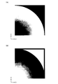
図3(A)(B)に本実施形態で使用されるテクスチャ(リング状テクスチャ)の例を示す。図3(A)のテクスチャは、テクスチャの円中心から円外周に向かうにつれて、テクセル値(α値、色の輝度)が単調増加するテクセル値パターン(グラディエーションパターン)を有するテクスチャである。また図3(B)のテクスチャは、テクスチャの円中心から円外周に向かうにつれて、テクセル値(α値、色の輝度)が単調減少するテクセル値パターン(グラディエーションパターン)を有するテクスチャである。なお図3(A)(B)のように全円形状のテクスチャではなく、図4(A)(B)のような1/4円形状のテクスチャを使用してもよい。或いは半円形状でもよい。図4(A)(B)の場合にも円中心から円外周に向かうにつれてテクセル値が単調増加又は単調減少している。 FIGS. 3A and 3B show examples of texture (ring texture) used in this embodiment. The texture in FIG. 3A is a texture having a texel value pattern (gradation pattern) in which the texel value (α value, color luminance) monotonously increases from the circle center of the texture toward the circle outer periphery. The texture in FIG. 3B is a texture having a texel value pattern (gradation pattern) in which the texel value (α value, color brightness) monotonously decreases from the center of the circle to the outer circumference of the circle. Note that a ¼ circular texture as shown in FIGS. 4A and 4B may be used instead of the full circular texture as shown in FIGS. Alternatively, it may be semicircular. 4A and 4B, the texel value monotonously increases or monotonously decreases from the center of the circle toward the outer periphery of the circle.
例えば図3(A)、図4(A)において、テクスチャの円中心のα値(広義にはテクセル値)を0.0(透明のα値)に設定し、円外周のα値を1.0(不透明のα値)に設定する。このようなテクスチャを図2の手法でオブジェクトOBにマッピングして、αプレーンを生成し、このαプレーンを用いてオブジェクトOBの画像とその背景画像をα合成すれば、図5(A)に示す画像を生成できる。図5(A)ではオブジェクトOBの中心部分は透明で背景画像が透けて見える一方で、輪郭部分(周縁部分)は不透明に見え、ガラスのような質感を得ることができる。別の言い方をすれば、オブジェクトOBの輪郭強調表現を実現できる。 For example, in FIGS. 3A and 4A, the α value (texel value in a broad sense) of the circle center of the texture is set to 0.0 (transparent α value), and the α value of the circle outer periphery is set to 1. Set to 0 (opaque α value). If such a texture is mapped to the object OB by the method shown in FIG. 2 to generate an α plane, and the α plane is used to α-synthesize the image of the object OB and its background image, the result shown in FIG. An image can be generated. In FIG. 5A, the center portion of the object OB is transparent and the background image can be seen through, while the outline portion (peripheral portion) looks opaque and a glass-like texture can be obtained. In other words, the contour emphasis expression of the object OB can be realized.
一方、図3(B)、図4(B)において、テクスチャの円中心のα値を1.0(不透明)に設定し、円外周のα値を0.0(透明)に設定する。このようなテクスチャをマッピングしてαプレーンを生成して、オブジェクトOBの画像と背景画像をα合成すれば、中心部分が不透明になる一方で、輪郭部分が透明になる輪郭ぼかし表現を実現できる。これにより輪郭部分を背景に溶け込ますことができ、輪郭部分に生じるエリアシング等を防止できる。 On the other hand, in FIGS. 3B and 4B, the α value at the center of the circle of the texture is set to 1.0 (opaque), and the α value at the outer periphery of the circle is set to 0.0 (transparent). If an α plane is generated by mapping such a texture and the image of the object OB and the background image are α-combined, it is possible to realize a contour blur expression in which the center portion becomes opaque while the contour portion becomes transparent. As a result, the contour portion can be melted into the background, and aliasing that occurs in the contour portion can be prevented.
また図3(A)、図4(A)において、テクスチャの円中心の輝度(広義にはテクセル値)を最小値(最も暗い輝度)に設定し、円外周の輝度を最大値(最も明るい輝度)に設定する。このようなテクスチャを例えば骨のオブジェクトOBにマッピングすれば(骨の元絵テクスチャと輝度テクスチャのマルチテクスチャマッピングを行えば)、図5(B)に示す画像を生成できる。図5(B)では骨オブジェクトOBの輪郭部分がぼやけて見える一方で、中心部分が黒ずんで見える。これにより、あたかもレントゲンで撮ったかのように見える骨画像を生成できる。なお図3(B)、図4(B)のように、テクスチャの円中心の輝度を最大値に設定し、円外周の輝度を最小値に設定してもよい。 3A and 4A, the luminance at the center of the circle of the texture (texel value in a broad sense) is set to the minimum value (darkest luminance), and the luminance around the circle is set to the maximum value (brightest luminance). ). If such a texture is mapped to, for example, a bone object OB (multi-texture mapping of a bone original picture texture and a luminance texture is performed), an image shown in FIG. 5B can be generated. In FIG. 5B, the outline portion of the bone object OB appears blurred while the center portion appears dark. This makes it possible to generate a bone image that looks as if it was taken with an X-ray. As shown in FIGS. 3B and 4B, the luminance at the center of the circle of the texture may be set to the maximum value, and the luminance at the outer periphery of the circle may be set to the minimum value.
本実施形態では、仮想カメラVCが動いたり、オブジェクトOBが動いて、VCとOBの相対的な位置関係が変化しても、常に図5(A)(B)に示すような輪郭強調画像、輪郭ぼかし画像を生成できるという利点がある。しかも本実施形態では、図3(A)〜図4(B)のようなテクスチャを用意して、図2の手法でマッピングするだけで図5(A)(B)の画像表現を実現できる。従って仮想カメラの視線ベクトルと法線ベクトルの内積を求めて輪郭強調画像や輪郭ぼかし画像を生成する手法に比べて、処理負荷を格段に軽減できる。 In the present embodiment, even if the virtual camera VC moves or the object OB moves and the relative positional relationship between VC and OB changes, the contour-enhanced image as shown in FIGS. There is an advantage that a contour blurred image can be generated. Moreover, in this embodiment, the image representations of FIGS. 5A and 5B can be realized simply by preparing textures as shown in FIGS. 3A to 4B and mapping them by the method of FIG. Therefore, the processing load can be remarkably reduced as compared with the method of obtaining the inner product of the line-of-sight vector and the normal vector of the virtual camera and generating the contour-enhanced image and the contour-blurred image.
2.2 ゲームイベントに応じたテクスチャの設定
本実施形態では、オブジェクトに関連するゲームイベントが発生した場合に、発生したゲームイベントに応じたテクセル値パターン(グラディエーションパターン)のテクスチャを設定し、そのテクスチャを図2の手法でオブジェクトにマッピングしている。即ち発生するゲームイベントに応じて、異なるテクセル値パターンのテクスチャを図2の手法でマッピングする。
2.2 Setting Texture According to Game Event In this embodiment, when a game event related to an object occurs, a texture of a texel value pattern (gradation pattern) corresponding to the generated game event is set, The texture is mapped to the object by the method shown in FIG. That is, according to the generated game event, textures of different texel value patterns are mapped by the method of FIG.
例えば、オブジェクトが消滅するゲームイベントが発生した場合には、図6(A)〜(D)のようにテクセル値パターンが時間経過(フレーム経過)に伴い徐々に変化するテクスチャをオブジェクトにマッピングする。 For example, when a game event in which the object disappears occurs, a texture in which the texel value pattern gradually changes with time (frame progress) is mapped to the object as shown in FIGS.
図6(A)ではテクスチャの円の全ての領域においてα値(テクセル値)が1.0(不透明のα値)になっている。図6(B)では円中心においてα値が0.0(透明のα値)になり、円中心と円外周の間でα値が0.0<α<1.0(半透明)になり、円外周でα値が1.0(不透明)になっている。図6(C)ではα値が0.0になる範囲が広がっており、図6(D)ではテクスチャの円の全ての領域においてα値が0.0になっている。 In FIG. 6A, the α value (texel value) is 1.0 (opaque α value) in all regions of the texture circle. In FIG. 6B, the α value is 0.0 (transparent α value) at the center of the circle, and the α value is 0.0 <α <1.0 (translucent) between the center of the circle and the outer periphery of the circle. The α value is 1.0 (opaque) on the outer circumference of the circle. In FIG. 6C, the range in which the α value is 0.0 is widened, and in FIG. 6D, the α value is 0.0 in all regions of the texture circle.
そして時間がT1、T2、T3、T4と経過した場合に、時間T1においては図6(A)のテクスチャ、T2、T3、T4においては図6(B)(C)(D)のテクスチャというように、オブジェクトの消滅時に、テクセル値パターンが時間経過に伴い変化するテクスチャが、オブジェクトにマッピングされる。 Then, when the times T1, T2, T3, and T4 have elapsed, the texture shown in FIG. 6A at the time T1, and the textures shown in FIGS. 6B, 6C, and 6D at the times T2, T3, and T4. Furthermore, when the object disappears, a texture whose texel value pattern changes with time is mapped to the object.
このようにすれば、オブジェクトの中心部分からオブジェクトの輪郭部分に向かって時間経過に伴いオブジェクトが徐々に透明になる画像を生成できる。例えば図6(A)(時間T1)では、オブジェクトが通常に表示され(不透明)、図6(B)(C)(時間T2、T3)ではオブジェクトの中心から透明になり、図6(D)では輪郭部分を含めたオブジェクトの全てが透明になる。このようにすることで、演出効果の高いオブジェクトの消滅表現を実現できる。 In this way, it is possible to generate an image in which the object gradually becomes transparent with time from the center part of the object toward the contour part of the object. For example, in FIG. 6A (time T1), the object is normally displayed (opaque), and in FIGS. 6B and 6C (time T2, T3), the object becomes transparent from the center, and FIG. Now all the objects including the outline are transparent. By doing so, it is possible to realize the disappearance expression of the object with a high production effect.
なお図6(A)〜(D)は、オブジェクトの中心部分から輪郭部分に向かって時間経過に伴いオブジェクトが徐々に透明になるテクセル値パターン(α値パターン)になっているが、オブジェクトの輪郭部分からオブジェクトの中心部分に向かって時間経過に伴いオブジェクトが徐々に透明になるようなテクセル値パターンを採用してもよい。この場合には円外周から徐々にα値が0.0から1.0に変化するテクセル値パターンを設定すればよい。 6A to 6D show a texel value pattern (α value pattern) in which the object gradually becomes transparent with time from the center portion of the object toward the contour portion. You may employ | adopt the texel value pattern which an object becomes transparent gradually as time passes toward the center part of an object from a part. In this case, a texel value pattern in which the α value gradually changes from 0.0 to 1.0 from the outer periphery of the circle may be set.
オブジェクトが出現するゲームイベントが発生した場合には、例えば図7(A)〜(D)のようなテクスチャをオブジェクトにマッピングする。 When a game event in which an object appears occurs, for example, textures as shown in FIGS. 7A to 7D are mapped to the object.
図7(A)ではテクスチャの円の全ての領域においてα値が0.0(透明)になっている。図7(B)(C)では円中心から円外周に向かって徐々にα値が0.0から1.0(不透明)に変化し、図7(D)では円の全ての領域においてα値が1.0になっている。 In FIG. 7A, the α value is 0.0 (transparent) in all regions of the texture circle. 7B and 7C, the α value gradually changes from 0.0 to 1.0 (opaque) from the center of the circle toward the outer periphery of the circle, and in FIG. 7D, the α value in all regions of the circle. Is 1.0.
このようにすれば、オブジェクトの中心部分からオブジェクトの輪郭部分に向かって時間経過に伴いオブジェクトが徐々に不透明(出現)になる画像を生成できる。例えば図7(A)(時間T1)では、オブジェクトは表示されず(オブジェクトが透明となり)、図7(B)(C)(時間T2、T3)ではオブジェクトの中心から不透明になり(オブジェクトが出現し)、図7(D)では輪郭部分を含めたオブジェクトの全てが不透明になる(オブジェクトの全てが表示される)。このようにすれば、演出度の高い出現表現を実現できる。 In this way, it is possible to generate an image in which the object gradually becomes opaque (appears) with the passage of time from the center portion of the object toward the contour portion of the object. For example, in FIG. 7A (time T1), the object is not displayed (the object becomes transparent), and in FIGS. 7B and 7C (time T2, T3), it becomes opaque from the center of the object (the object appears). In FIG. 7D, all the objects including the outline portion become opaque (all the objects are displayed). In this way, it is possible to realize an appearance expression with a high degree of production.
なお図7(A)〜(D)は、オブジェクトの中心部分から輪郭部分に向かって時間経過に伴いオブジェクトが徐々に不透明になるテクセル値パターン(α値パターン)になっているが、オブジェクトの輪郭部分からオブジェクトの中心部分に向かって時間経過に伴いオブジェクトが徐々に不透明になるテクセル値パターンを採用してもよい。この場合には円外周から徐々にα値が1.0から0.0に変化するようにテクセル値パターンを設定すればよい。 7A to 7D show a texel value pattern (α value pattern) in which the object gradually becomes opaque as time passes from the central part of the object toward the contour part. A texel value pattern in which the object gradually becomes opaque as time passes from the part toward the center part of the object may be adopted. In this case, the texel value pattern may be set so that the α value gradually changes from 1.0 to 0.0 from the outer periphery of the circle.
また図6(A)〜(D)、図7(A)〜(D)では、テクスチャのパターン数が4個の場合を例示しているが、パターン数は、2個、3個でもよいし、5個以上であってもよい。 6 (A) to (D) and FIGS. 7 (A) to (D) exemplify the case where the number of texture patterns is four, the number of patterns may be two or three. It may be 5 or more.
またゲームイベントは、消滅イベントや出現イベントには限定されず、攻撃等がヒットするヒットイベントでもよい。例えば図8では、オブジェクトOB1(キャラクタ)に対して他のオブジェクトOB2(他のキャラクタ)の攻撃(パンチ、キック、或いはショット等等)がヒットするイベントが発生している。この場合には、オブジェクトOB1のヒット部位に応じたテクセル値パターン(グラディエーションパターン)のテクスチャをOB1にマッピングする。或いはオブジェクトOB2の攻撃の種類に応じたテクセル値パターンのテクスチャをオブジェクトOB1にマッピングする。 The game event is not limited to the disappearance event or the appearance event, and may be a hit event in which an attack or the like is hit. For example, in FIG. 8, an event occurs in which an attack (punch, kick, shot, etc.) of another object OB2 (other character) hits the object OB1 (character). In this case, the texture of the texel value pattern (gradation pattern) corresponding to the hit part of the object OB1 is mapped to OB1. Alternatively, the texture of the texel value pattern corresponding to the type of attack of the object OB2 is mapped to the object OB1.
そしてオブジェクトOB1のヒット部位が急所(顎等)であった場合には、図6(A)〜(D)のようなテクセル値パターンのテクスチャをオブジェクトOB1にマッピングし、OB1を消滅させる。 If the hit part of the object OB1 is a stubborn place (such as a chin), the texture of the texel value pattern as shown in FIGS. 6A to 6D is mapped to the object OB1, and OB1 is extinguished.
一方、オブジェクトOB1のヒット部位が急所以外である場合には、攻撃のヒット時に、図2のテクスチャマッピング手法を用いて図5(B)に示すようなオブジェクトOB1の骨画像(レントゲン画像)を表示する。そしてオブジェクトOB2の攻撃の種類に応じて異なるテクセル値パターンのテクスチャを、オブジェクトOB1にマッピングする。 On the other hand, if the hit part of the object OB1 is other than the critical point, the bone image (X-ray image) of the object OB1 as shown in FIG. 5B is displayed by using the texture mapping method of FIG. To do. Then, textures having different texel value patterns according to the type of attack of the object OB2 are mapped to the object OB1.
具体的には、オブジェクトOB2の攻撃の種類が大技攻撃である場合には、オブジェクトOB1の骨パーツオブジェクトに対して、図3(A)、図4(A)に示すようなテクスチャを図2の手法でマッピングする。これにより、オブジェクトOB1の骨の中心部分が黒ずんで見えるOB1のレントゲン画像を生成できる。一方、オブジェクトOB2の攻撃の種類が小技攻撃である場合には、オブジェクトOB1の骨パーツオブジェクトに対して、図3(B)、図4(B)に示すようなテクスチャを図2の手法でマッピングする。これにより、オブジェクトOB1の骨の輪郭部分がぼやけて見えるOB1のレントゲン画像を生成できる。このようにオブジェクトOB2の攻撃の種類に応じて、オブジェクトOB1にマッピングするテクスチャのテクセル値パターンを異ならせることで、少ない処理負荷で多様な画像表現を実現できる。 Specifically, when the type of attack of the object OB2 is a large skill attack, the texture as shown in FIGS. 3A and 4A is applied to the bone part object of the object OB1 as shown in FIG. Use the method of mapping. Thereby, the X-ray image of OB1 in which the central part of the bone of the object OB1 appears dark can be generated. On the other hand, when the attack type of the object OB2 is a small skill attack, the texture shown in FIGS. 3B and 4B is applied to the bone part object of the object OB1 by the method of FIG. Map. Thereby, the X-ray image of OB1 in which the contour portion of the bone of the object OB1 appears blurred can be generated. In this manner, by varying the texture texel value pattern mapped to the object OB1 according to the type of attack of the object OB2, various image representations can be realized with a small processing load.
3.本実施形態の処理
次に、本実施形態の詳細な処理例について図9〜図13のフローチャートを用いて説明する。
3. Processing of this Embodiment Next, a detailed processing example of this embodiment will be described using the flowcharts of FIGS. 9 to 13.
図9は、図2のテクスチャマッピング手法でαプレーンを生成し、生成されたαプレーンでα合成を行う処理のフローチャートである。まずオブジェクトをオブジェクト空間に配置設定する(ステップS1)。具体的には操作部により入力された操作情報やプログラムなどに基づいて、オブジェクト空間内でのオブジェクトの位置や回転角度を求めて、オブジェクト空間に配置設定する。そして、仮想カメラをオブジェクト空間に配置設定する(ステップS2)。具体的にはオブジェクトの位置情報や仮想カメラデータなどに基づいて、仮想カメラの位置や回転角度を求めて、オブジェクト空間に配置設定する。 FIG. 9 is a flowchart of a process of generating an α plane by the texture mapping method of FIG. 2 and performing α synthesis using the generated α plane. First, an object is arranged and set in the object space (step S1). Specifically, the position and rotation angle of the object in the object space are obtained based on operation information and a program input by the operation unit, and the arrangement is set in the object space. Then, the virtual camera is arranged and set in the object space (step S2). Specifically, the position and rotation angle of the virtual camera are obtained based on the position information of the object, virtual camera data, and the like, and are arranged and set in the object space.
次にオブジェクトの透視変換等のジオメトリ処理を行う(ステップS3)。例えばオブジェクトについてのワールド座標系からカメラ座標系(視点座標系)への座標変換や、カメラ座標系からスクリーン座標系への座標変換を行う。そしてカメラ座標系又はスクリーン座標系でのオブジェクトの法線ベクトルの座標成分(NX,NY)を求める(ステップS4。図2参照)。 Next, geometry processing such as perspective transformation of the object is performed (step S3). For example, coordinate conversion from the world coordinate system to the camera coordinate system (viewpoint coordinate system) or coordinate conversion from the camera coordinate system to the screen coordinate system is performed for the object. Then, the coordinate component (NX, NY) of the normal vector of the object in the camera coordinate system or the screen coordinate system is obtained (step S4, see FIG. 2).
次に、法線ベクトルの座標成分(NX,NY)の値域を(−0.1〜1.0)から(0.0〜1.0)に正規化して、テクスチャ座標(U,V)を求める(ステップS5)。そして求められたテクスチャ座標に基づいてテクスチャをオブジェクトにマッピングして、αプレーンを生成する(ステップS6)。次に、ジオメトリ処理後のオブジェクトの画像(元画像)と背景の画像を、生成されたαプレーンに基づいてα合成する(ステップS7)。これにより図5(A)に示すようなオブジェクトの輪郭強調画像(或いは輪郭ぼかし画像)を生成できる。 Next, the range of the coordinate component (NX, NY) of the normal vector is normalized from (−0.1 to 1.0) to (0.0 to 1.0), and the texture coordinates (U, V) are obtained. Obtained (step S5). Then, the texture is mapped to the object based on the obtained texture coordinates to generate an α plane (step S6). Next, the object image (original image) and the background image after the geometry processing are subjected to α synthesis based on the generated α plane (step S7). As a result, an outline-enhanced image (or outline-blurred image) of the object as shown in FIG. 5A can be generated.
図10は、オブジェクトの元画像に図2の手法でマルチテクスチャマッピングを行う処理のフローチャートである。ステップS11〜S15までは、図9のステップS1〜S5と同様である。そしてステップS16では、ステップS15で求められたテクスチャ座標に基づいてテクスチャをオブジェクトにマッピングし、得られた画像をオブジェクトの画像(元画像)に加算合成する(ステップS16)。これにより図5(B)に示すような骨オブジェクトのレントゲン画像を生成できる。 FIG. 10 is a flowchart of processing for performing multi-texture mapping on the original image of an object using the method of FIG. Steps S11 to S15 are the same as steps S1 to S5 in FIG. In step S16, the texture is mapped to the object based on the texture coordinates obtained in step S15, and the obtained image is added and synthesized to the object image (original image) (step S16). Thereby, the X-ray image of the bone object as shown in FIG. 5B can be generated.
図11は本実施形態の比較例の処理のフローチャートである。まず透明度パラメータを設定する(ステップS21)。具体的には、仮想カメラの視線方向に垂直なオブジェクトの面の透明度TR1や、仮想カメラの視線方向に平行なオブジェクトの面の透明度TR2や、TR1とTR2をサイン関数で補間する割合RTRを設定する。そして、オブジェクトの面の法線ベクトルと仮想カメラの視線方向ベクトルをベクトル演算し、合成ベクトルの長さを求める(ステップS22)。次に、合成ベクトルの長さと、設定された透明度パラメータに基づき透明度を求める(ステップS23)。そして求められた透明度をオブジェクトの頂点α値に設定し、オブジェクトの画像と背景画像をα合成する(ステップS24)。 FIG. 11 is a flowchart of the process of the comparative example of this embodiment. First, a transparency parameter is set (step S21). Specifically, the transparency TR1 of the object plane perpendicular to the viewing direction of the virtual camera, the transparency TR2 of the object plane parallel to the viewing direction of the virtual camera, and the ratio RTR for interpolating TR1 and TR2 with a sine function are set. To do. Then, the normal vector of the object plane and the visual direction vector of the virtual camera are vector-calculated to obtain the length of the combined vector (step S22). Next, the transparency is obtained based on the length of the combined vector and the set transparency parameter (step S23). Then, the obtained transparency is set to the vertex α value of the object, and the object image and the background image are α-combined (step S24).
図11の比較例では、輪郭強調画像を生成するのに、ステップS21に示すような透明度パラメータの設定や、ステップS22、S23に示すようなベクトル演算処理等が必要になる。このため処理負荷が重くなる。これに対して図9、図10の本実施形態では、図3(A)〜図4(B)のようなテクスチャを用意し、このテクスチャをオブジェクトにマッピングするだけで輪郭強調画像や輪郭ぼかし画像を生成できる。このため図11の比較例に比べて処理負荷を軽減できる。 In the comparative example of FIG. 11, setting of a transparency parameter as shown in step S21, vector calculation processing as shown in steps S22 and S23, and the like are required to generate an edge-enhanced image. This increases the processing load. On the other hand, in the present embodiment of FIGS. 9 and 10, a texture as shown in FIGS. 3A to 4B is prepared, and an edge-enhanced image or an edge-blurred image is obtained simply by mapping the texture to an object. Can be generated. Therefore, the processing load can be reduced as compared with the comparative example of FIG.
また通常の環境マッピングにおいては、仮想カメラの注視点に球状の鏡を置き、そこに映り込んだ画像、或いは注視点から仮想カメラ側を見た風景画像を魚眼レンズ風に処理した画像を、テクスチャとして用意する必要がある。これに対して図9、図10の本実施形態の手法では、図3(A)〜図4(B)に示すように、仮想カメラとは無関係に、円状で中心から外周に向かって単色のグラディエーションを有する画像が、テクスチャとして用意され、このテクスチャが仮想カメラの方向からオブジェクトにマッピングされる。 In normal environment mapping, a spherical mirror is placed at the gazing point of the virtual camera, and an image reflected on the virtual camera or a landscape image viewed from the gazing point on the virtual camera side is processed as a fisheye lens texture. It is necessary to prepare. On the other hand, in the method of the present embodiment shown in FIGS. 9 and 10, as shown in FIGS. 3A to 4B, a single color is formed from the center toward the outer periphery regardless of the virtual camera. An image having the following gradient is prepared as a texture, and this texture is mapped to the object from the direction of the virtual camera.
図12は、図2のテクスチャマッピング手法を利用してオブジェクトの消滅表示や出現表示を実現する処理のフローチャートである。まずオブジェクトの消滅又は出現のゲームイベントが発生したか否かを判断する(ステップS31)。そして消滅又は出現のゲームイベントが発生した場合には、経過時間の計測処理を開始する(ステップS32)。具体的には、オブジェクトが消滅又は出現したフレームからのフレームカウント処理を開始する。 FIG. 12 is a flowchart of processing for realizing the disappearance display and appearance display of an object using the texture mapping method of FIG. First, it is determined whether an object disappearance or appearance game event has occurred (step S31). If a disappearing or appearing game event occurs, the elapsed time measurement process is started (step S32). Specifically, the frame count process is started from the frame where the object disappears or appears.
次に、異なるテクセル値パターン(α値パターン)を有する複数のテクスチャの中から、経過時間(フレームカウント)に応じたテクスチャを指定する(ステップS33)。具体的にはオブジェクトの消滅表示の場合には、図6(A)〜(D)のテクスチャのいずれかを経過時間に基づいて指定する。一方、オブジェクトの出現表示の場合には、図7(A)〜(D)のテクスチャのいずれかを経過時間に基づいて指定する。このように本実施形態ではゲームイベント(消滅又は出現イベント)に応じて、異なるテクセル値パターンを有するテクスチャをオブジェクトにマッピングしている。 Next, a texture corresponding to the elapsed time (frame count) is designated from a plurality of textures having different texel value patterns (α value patterns) (step S33). Specifically, in the case of object disappearance display, one of the textures in FIGS. 6A to 6D is designated based on the elapsed time. On the other hand, in the case of object appearance display, any one of the textures in FIGS. 7A to 7D is designated based on the elapsed time. As described above, in the present embodiment, textures having different texel value patterns are mapped to objects in accordance with game events (disappearance or appearance events).
次に、指定されたテクスチャを、オブジェクトの面の法線ベクトルにより得られたテクスチャ座標に基づいてオブジェクトにマッピングし、αプレーンを生成する(ステップS34)。具体的には図2のテクスチャマッピング手法でαプレーンを生成する。そして、ジオメトリ処理後のオブジェクトの画像と背景の画像を、生成されたαプレーンに基づいてα合成する(ステップS35)。これにより、オブジェクトの消滅表示や出現表示を実現できる。 Next, the designated texture is mapped to the object based on the texture coordinates obtained from the normal vector of the surface of the object to generate an α plane (step S34). Specifically, the α plane is generated by the texture mapping method of FIG. Then, the image of the object after the geometry processing and the background image are subjected to α synthesis based on the generated α plane (step S35). Thereby, disappearance display and appearance display of the object can be realized.
図13は、オブジェクトのヒット部位や攻撃の種類に応じて、図2の手法でマッピングされるテクスチャの設定を異ならせる処理のフローチャートである。まず、他のオブジェクトの攻撃がオブジェクトにヒットしたか否かを判断する(ステップS41。図8参照)。そしてヒットした場合には、オブジェクトの急所に攻撃がヒットしたか否かを判断する(ステップS42)。そして急所にヒットした場合には、消滅演出を行う(ステップS43)。具体的には、オブジェクトの面の法線ベクトルにより得られたテクスチャ座標に基づくテクスチャマッピングにより、図6(A)〜(D)のテクスチャを使用して、オブジェクトの消滅表示を行う。 FIG. 13 is a flowchart of processing for changing the texture setting mapped by the method of FIG. 2 according to the hit part of the object and the type of attack. First, it is determined whether or not an attack of another object hits the object (step S41, see FIG. 8). If there is a hit, it is determined whether or not the attack hits the critical point of the object (step S42). And when it hits a critical place, an extinction effect is performed (step S43). Specifically, the disappearance display of the object is performed using the textures shown in FIGS. 6A to 6D by texture mapping based on the texture coordinates obtained from the normal vector of the surface of the object.
急所以外のヒット部位に攻撃がヒットした場合には、攻撃は大技か否かを判断する(ステップS44)。そして大技である場合には、大技演出を行う(ステップS45)。具体的には、オブジェクトの法線ベクトルにより得られたテクスチャ座標に基づくテクスチャマッピングにより、例えば図3(A)、図4(A)のテクスチャを使用して、オブジェクトの骨の輪郭強調表示を行う。 If the attack hits a hit site other than the critical point, it is determined whether or not the attack is a great skill (step S44). If it is a great skill, a great skill effect is performed (step S45). Specifically, the outline of the bone of the object is highlighted by using texture mapping based on the texture coordinates obtained from the normal vector of the object, for example, using the texture shown in FIGS. 3 (A) and 4 (A). .
一方、攻撃が小技である場合には小技演出を行う(ステップS46)。具体的には、オブジェクトの法線ベクトルにより得られたテクスチャ座標に基づくテクスチャマッピングにより、例えば図3(B)、図4(B)のテクスチャを使用して、オブジェクトの骨の輪郭ぼかし表示を行う。このように本実施形態では、オブジェクトのヒット部位や攻撃の種類に応じて、マッピングされるテクスチャのテクセル値パターンを異ならせている。 On the other hand, if the attack is a small skill, a small skill effect is performed (step S46). Specifically, the outline of the bone of the object is blurred by using texture mapping based on the texture coordinates obtained from the normal vector of the object, for example, using the textures shown in FIGS. 3B and 4B. . As described above, in the present embodiment, the texel value pattern of the texture to be mapped is made different according to the hit part of the object and the type of attack.
4.ハードウェア構成
図14に本実施形態を実現できるハードウェア構成の例を示す。メインプロセッサ900は、CD982(情報記憶媒体)に格納されたプログラム、通信インターフェース990を介してダウンロードされたプログラム、或いはROM950に格納されたプログラムなどに基づき動作し、ゲーム処理、画像処理、音処理などを実行する。コプロセッサ902は、メインプロセッサ900の処理を補助するものであり、マトリクス演算(ベクトル演算)を高速に実行する。例えばオブジェクトを移動させたり動作(モーション)させる物理シミュレーションに、マトリクス演算処理が必要な場合には、メインプロセッサ900上で動作するプログラムが、その処理をコプロセッサ902に指示(依頼)する。
4). Hardware Configuration FIG. 14 shows an example of a hardware configuration capable of realizing this embodiment. The
ジオメトリプロセッサ904は、メインプロセッサ900上で動作するプログラムからの指示に基づいて、座標変換、透視変換、光源計算、曲面生成などのジオメトリ処理を行うものであり、マトリクス演算を高速に実行する。データ伸張プロセッサ906は、圧縮された画像データや音データのデコード処理を行ったり、メインプロセッサ900のデコード処理をアクセレートする。これにより、オープニング画面やゲーム画面において、MPEG方式等で圧縮された動画像を表示できる。
The
描画プロセッサ910は、ポリゴンや曲面などのプリミティブ面で構成されるオブジェクトの描画(レンダリング)処理を実行する。オブジェクトの描画の際には、メインプロセッサ900は、DMAコントローラ970を利用して、描画データを描画プロセッサ910に渡すと共に、必要であればテクスチャ記憶部924にテクスチャを転送する。すると描画プロセッサ910は、描画データやテクスチャに基づいて、Zバッファなどを利用した隠面消去を行いながら、オブジェクトをフレームバッファ922に描画する。また描画プロセッサ910は、αブレンディング(半透明処理)、デプスキューイング、ミップマッピング、フォグ処理、バイリニア・フィルタリング、トライリニア・フィルタリング、アンチエリアシング、シェーディング処理なども行う。1フレーム分の画像がフレームバッファ922に書き込まれるとその画像はディスプレイ912に表示される。
The drawing
サウンドプロセッサ930は、多チャンネルのADPCM音源などを内蔵し、BGM、効果音、音声などのゲーム音を生成し、スピーカ932を介して出力する。ゲームコントローラ942やメモリカード944からのデータはシリアルインターフェース940を介して入力される。
The
ROM950にはシステムプログラムなどが格納される。業務用ゲームシステムの場合にはROM950が情報記憶媒体として機能し、ROM950に各種プログラムが格納される。なおROM950の代わりにハードディスクを利用してもよい。RAM960は各種プロセッサの作業領域となる。DMAコントローラ970は、プロセッサ、メモリ間でのDMA転送を制御する。CDドライブ980は、プログラム、画像データ、或いは音データなどが格納されるCD982にアクセスする。通信インターフェース990はネットワーク(通信回線、高速シリアルバス)を介して外部との間でデータ転送を行う。
The
なお本実施形態の各部(各手段)の処理は、その全てをハードウェアのみにより実現してもよいし、情報記憶媒体に格納されるプログラムや通信インターフェースを介して配信されるプログラムにより実現してもよい。或いは、ハードウェアとプログラムの両方により実現してもよい。 The processing of each unit (each unit) in this embodiment may be realized entirely by hardware, or may be realized by a program stored in an information storage medium or a program distributed via a communication interface. Also good. Alternatively, it may be realized by both hardware and a program.
そして本実施形態の各部の処理をハードウェアとプログラムの両方により実現する場合には、情報記憶媒体には、ハードウェア(コンピュータ)を本実施形態の各部として機能させるためのプログラムが格納される。より具体的には、上記プログラムが、ハードウェアである各プロセッサ902、904、906、910、930に処理を指示すると共に、必要であればデータを渡す。そして、各プロセッサ902、904、906、910、930は、その指示と渡されたデータとに基づいて本発明の各部の処理を実現する。
When the processing of each part of this embodiment is realized by both hardware and a program, a program for causing the hardware (computer) to function as each part of this embodiment is stored in the information storage medium. More specifically, the program instructs the
なお本発明は、上記実施形態で説明したものに限らず、種々の変形実施が可能である。 The present invention is not limited to that described in the above embodiment, and various modifications can be made.
例えば、明細書又は図面中の記載において広義や同義な用語(テクセル値、テクセル値パターン、プリミティブ面等)として引用された用語(α値・輝度、グラディエーションパターン、ポリゴン等)は、明細書又は図面中の他の記載においても広義や同義な用語に置き換えることができる。 For example, terms (α values / luminance, gradient patterns, polygons, etc.) cited as broad or synonymous terms (texel values, texel value patterns, primitive surfaces, etc.) in the description or drawings are described in the specification or In other descriptions in the drawings, terms can be replaced with terms having a broad meaning or the same meaning.
また、本発明のうち従属請求項に係る発明においては、従属先の請求項の構成要件の一部を省略する構成とすることもできる。また、本発明の1の独立請求項に係る発明の要部を、他の独立請求項に従属させることもできる。 In the invention according to the dependent claims of the present invention, a part of the constituent features of the dependent claims can be omitted. Moreover, the principal part of the invention according to one independent claim of the present invention can be made dependent on another independent claim.
またテクスチャのマッピング処理も、本実施形態で説明したものに限定されず、これらと均等な変換処理も本発明の範囲に含まれる。また本発明は種々のゲームに適用できる。また本発明は、業務用ゲームシステム、家庭用ゲームシステム、多数のプレーヤが参加する大型アトラクションシステム、シミュレータ、マルチメディア端末、ゲーム画像を生成するシステムボード、携帯端末等の種々の画像生成システムに適用できる。 Also, the texture mapping process is not limited to that described in the present embodiment, and a conversion process equivalent to these is also included in the scope of the present invention. The present invention can be applied to various games. Further, the present invention is applied to various image generation systems such as a business game system, a home game system, a large attraction system in which a large number of players participate, a simulator, a multimedia terminal, a system board for generating a game image, and a portable terminal. it can.
100 処理部、110 オブジェクト空間設定部、112 移動・動作処理部、
114 仮想カメラ制御部、116 テクスチャ座標演算部、
120 画像生成部、122 隠面消去部、
124 テクスチャマッピング部、126 α合成部、
130 音生成部、160 操作部、170 記憶部、
172 描画バッファ、174 Zバッファ、176 テクスチャ記憶部、
180 情報記憶媒体、190 表示部、
192 音出力部、194 携帯型情報記憶装置、196 通信部
100 processing unit, 110 object space setting unit, 112 movement / motion processing unit,
114 virtual camera control unit, 116 texture coordinate calculation unit,
120 image generation unit, 122 hidden surface removal unit,
124 texture mapping unit, 126 α synthesis unit,
130 sound generation unit, 160 operation unit, 170 storage unit,
172 drawing buffer, 174 Z buffer, 176 texture storage unit,
180 information storage medium, 190 display unit,
192 sound output unit, 194 portable information storage device, 196 communication unit
Claims (15)
テクスチャを記憶するテクスチャ記憶部と、
カメラ座標系又はスクリーン座標系でのオブジェクトの面の法線ベクトルの座標成分を求め、求められた座標成分に基づいてテクスチャ座標を求めるテクスチャ座標演算部と、
求められたテクスチャ座標に基づいて、所与のテクセル値パターンを有するテクスチャをオブジェクトにマッピングするテクスチャマッピング部とを含み、
前記テクスチャマッピング部が、
仮想カメラの視線方向とオブジェクトの法線ベクトル方向が平行である場合のテクスチャ座標の指定位置であるテクスチャの円中心から、前記視線方向と前記法線ベクトル方向が直交する場合のテクスチャ座標の指定位置であるテクスチャの円外周に向かうにつれて、テクセル値が単調増加又は単調減少するテクセル値パターンを有するテクスチャを、オブジェクトにマッピングすることで、オブジェクトの輪郭強調画像又は輪郭ぼかし画像を生成することを特徴とする画像生成システム。 An image generation system for generating an image visible from a virtual camera in an object space,
A texture storage unit for storing textures;
Obtaining a coordinate component of the normal vector of the surface of the object in the camera coordinate system or the screen coordinate system, and obtaining a texture coordinate based on the obtained coordinate component;
A texture mapping unit that maps a texture having a given texel value pattern to an object based on the determined texture coordinates;
The texture mapping unit is
Designated position of texture coordinates when the line-of-sight direction and the normal vector direction are orthogonal from the texture circle center, which is the designated position of the texture coordinates when the line-of-sight direction of the virtual camera and the normal vector direction of the object are parallel A texture having a texel value pattern in which the texel value monotonously increases or decreases monotonously as it goes toward the outer circumference of the texture is mapped to the object, thereby generating an edge-enhanced image or an edge-blurred image of the object. Image generation system.
テクスチャの前記テクセル値がα値を含み、
オブジェクトの画像と背景の画像とを、テクスチャの前記α値に基づいて合成するα合成部を含むことを特徴とする画像生成システム。 In claim 1 ,
The texel value of the texture includes an α value;
An image generation system comprising: an α synthesis unit that synthesizes an object image and a background image based on the α value of a texture.
前記テクスチャマッピング部が、
オブジェクトの中心部分からオブジェクトの輪郭部分に向かって時間経過に伴いオブジェクトが徐々に透明になるように、或いは、オブジェクトの輪郭部分からオブジェクトの中心部分に向かって時間経過に伴いオブジェクトが徐々に透明になるように、オブジェクトの消滅時にテクセル値パターンが時間経過に伴い変化するテクスチャをオブジェクトにマッピングすることを特徴とする画像生成システム。 In claim 2 ,
The texture mapping unit is
The object gradually becomes transparent with time from the object center to the object outline, or the object gradually becomes transparent with time from the object outline to the object center. As described above, an image generation system characterized by mapping a texture whose texel value pattern changes with time when an object disappears to an object.
前記テクスチャマッピング部が、
オブジェクトの中心部分からオブジェクトの輪郭部分に向かって時間経過に伴いオブジェクトが徐々に不透明になるように、或いは、オブジェクトの輪郭部分からオブジェクトの中心部分に向かって時間経過に伴いオブジェクトが徐々に不透明になるように、オブジェクトの出現時にテクセル値パターンが時間経過に伴い変化するテクスチャをオブジェクトにマッピングすることを特徴とする画像生成システム。 In claim 2 ,
The texture mapping unit is
The object gradually becomes opaque as time passes from the center part of the object to the outline part of the object, or the object gradually becomes opaque as time passes from the outline part of the object to the center part of the object. As described above, an image generation system characterized in that a texture whose texel value pattern changes with time when an object appears is mapped to the object.
前記テクスチャマッピング部が、
オブジェクトについてのゲームイベントが発生した場合に、発生したゲームイベントに応じたテクセル値パターンのテクスチャをオブジェクトにマッピングすることを特徴とする画像生成システム。 In any one of Claims 1 thru | or 4 ,
The texture mapping unit is
When the game event about an object generate | occur | produces, the texture of the texel value pattern according to the generated game event is mapped to an object.
テクスチャを記憶するテクスチャ記憶部と、 A texture storage unit for storing textures;
カメラ座標系又はスクリーン座標系でのオブジェクトの面の法線ベクトルの座標成分を求め、求められた座標成分に基づいてテクスチャ座標を求めるテクスチャ座標演算部と、 Obtaining a coordinate component of the normal vector of the surface of the object in the camera coordinate system or the screen coordinate system, and obtaining a texture coordinate based on the obtained coordinate component;
求められたテクスチャ座標に基づいて、所与のテクセル値パターンを有するテクスチャをオブジェクトにマッピングするテクスチャマッピング部とを含み、 A texture mapping unit that maps a texture having a given texel value pattern to an object based on the determined texture coordinates;
前記テクスチャマッピング部が、 The texture mapping unit is
仮想カメラの視線方向とオブジェクトの法線ベクトル方向が平行である場合のテクスチャ座標の指定位置であるテクスチャの円中心から、前記視線方向と前記法線ベクトル方向が直交する場合のテクスチャ座標の指定位置であるテクスチャの円外周に向かうにつれて、テクセル値が単調増加又は単調減少するテクセル値パターンを有するテクスチャであって、オブジェクトの中心部分からオブジェクトの輪郭部分に向かって時間経過に伴いオブジェクトが徐々に透明になるように、或いは、オブジェクトの輪郭部分からオブジェクトの中心部分に向かって時間経過に伴いオブジェクトが徐々に透明になるように、オブジェクトの消滅時にテクセル値パターンが時間経過に伴い変化するテクスチャをオブジェクトにマッピングすることを特徴とする画像生成システム。 Designated position of texture coordinates when the line-of-sight direction and the normal vector direction are orthogonal from the center of the texture circle, which is the designated position of texture coordinates when the line-of-sight direction of the virtual camera and the normal vector direction of the object are parallel The texture has a texel value pattern in which the texel value monotonously increases or decreases monotonically as it goes to the outer circumference of the texture, and the object gradually becomes transparent with time from the center of the object toward the contour of the object. Or the texture whose texel value pattern changes with the passage of time when the object disappears so that the object gradually becomes transparent with the passage of time from the contour of the object toward the center of the object. And features that map to That image generation system.
テクスチャを記憶するテクスチャ記憶部と、 A texture storage unit for storing textures;
カメラ座標系又はスクリーン座標系でのオブジェクトの面の法線ベクトルの座標成分を求め、求められた座標成分に基づいてテクスチャ座標を求めるテクスチャ座標演算部と、 Obtaining a coordinate component of the normal vector of the surface of the object in the camera coordinate system or the screen coordinate system, and obtaining a texture coordinate based on the obtained coordinate component;
求められたテクスチャ座標に基づいて、所与のテクセル値パターンを有するテクスチャをオブジェクトにマッピングするテクスチャマッピング部とを含み、 A texture mapping unit that maps a texture having a given texel value pattern to an object based on the determined texture coordinates;
前記テクスチャマッピング部が、 The texture mapping unit is
仮想カメラの視線方向とオブジェクトの法線ベクトル方向が平行である場合のテクスチャ座標の指定位置であるテクスチャの円中心から、前記視線方向と前記法線ベクトル方向が直交する場合のテクスチャ座標の指定位置であるテクスチャの円外周に向かうにつれて、テクセル値が単調増加又は単調減少するテクセル値パターンを有するテクスチャであって、オブジェクトの中心部分からオブジェクトの輪郭部分に向かって時間経過に伴いオブジェクトが徐々に不透明になるように、或いは、オブジェクトの輪郭部分からオブジェクトの中心部分に向かって時間経過に伴いオブジェクトが徐々に不透明になるように、オブジェクトの出現時にテクセル値パターンが時間経過に伴い変化するテクスチャをオブジェクトにマッピングすることを特徴とする画像生成システム。 Designated position of texture coordinates when the line-of-sight direction and the normal vector direction are orthogonal from the center of the texture circle, which is the designated position of texture coordinates when the line-of-sight direction of the virtual camera and the normal vector direction of the object are parallel The texture has a texel value pattern in which the texel value monotonously increases or decreases monotonously as it goes toward the outer circumference of the texture, and the object gradually becomes opaque as time elapses from the center portion of the object toward the contour portion of the object. Or the texture whose texel value pattern changes with the passage of time when the object appears so that the object gradually becomes opaque with the passage of time from the contour of the object toward the center of the object. Specially mapping to Image generation system to be.
前記テクスチャマッピング部が、
オブジェクトについてのゲームイベントが発生した場合に、発生したゲームイベントに応じたテクセル値パターンのテクスチャをオブジェクトにマッピングすることを特徴とする画像生成システム。 In claim 6 or 7 ,
The texture mapping unit is
When the game event about an object generate | occur | produces, the texture of the texel value pattern according to the generated game event is mapped to an object.
テクスチャを記憶するテクスチャ記憶部と、
カメラ座標系又はスクリーン座標系でのオブジェクトの面の法線ベクトルの座標成分を求め、求められた座標成分に基づいてテクスチャ座標を求めるテクスチャ座標演算部と、
求められたテクスチャ座標に基づいて、所与のテクセル値パターンを有するテクスチャをオブジェクトにマッピングするテクスチャマッピング部とを含み、
前記テクスチャマッピング部が、
他のオブジェクトの攻撃がオブジェクトにヒットした場合に、オブジェクトのヒット部位および他のオブジェクトの攻撃の種類に応じたテクセル値パターンのテクスチャをオブジェクトにマッピングすることを特徴とする画像生成システム。 An image generation system for generating an image visible from a virtual camera in an object space,
A texture storage unit for storing textures;
Obtaining a coordinate component of the normal vector of the surface of the object in the camera coordinate system or the screen coordinate system, and obtaining a texture coordinate based on the obtained coordinate component;
A texture mapping unit that maps a texture having a given texel value pattern to an object based on the determined texture coordinates;
The texture mapping unit is
An image generation system characterized in that, when an attack of another object hits the object, a texture of a texel value pattern corresponding to the hit part of the object and the type of attack of the other object is mapped to the object.
前記テクスチャマッピング部が、
オブジェクトの消滅時又は出現時に、テクセル値パターンが時間経過に伴い変化するテクスチャをオブジェクトにマッピングすることを特徴とする画像生成システム。 In claim 9 ,
Before Symbol texture mapping section,
An image generation system, wherein a texture in which a texel value pattern changes over time is mapped to an object when the object disappears or appears.
カメラ座標系又はスクリーン座標系でのオブジェクトの面の法線ベクトルの座標成分を求め、求められた座標成分に基づいてテクスチャ座標を求めるテクスチャ座標演算部と、
求められたテクスチャ座標に基づいて、所与のテクセル値パターンを有するテクスチャをオブジェクトにマッピングするテクスチャマッピング部として、
コンピュータを機能させ、
前記テクスチャマッピング部が、
仮想カメラの視線方向とオブジェクトの法線ベクトル方向が平行である場合のテクスチャ座標の指定位置であるテクスチャの円中心から、前記視線方向と前記法線ベクトル方向が直交する場合のテクスチャ座標の指定位置であるテクスチャの円外周に向かうにつれて、テクセル値が単調増加又は単調減少するテクセル値パターンを有するテクスチャを、オブジェクトにマッピングすることで、オブジェクトの輪郭強調画像又は輪郭ぼかし画像を生成することを特徴とするプログラム。 A program for generating an image visible from a virtual camera in an object space,
Obtaining a coordinate component of the normal vector of the surface of the object in the camera coordinate system or the screen coordinate system, and obtaining a texture coordinate based on the obtained coordinate component;
As a texture mapping unit that maps a texture having a given texel value pattern to an object based on the obtained texture coordinates,
Make the computer work,
The texture mapping unit is
Designated position of texture coordinates when the line-of-sight direction and the normal vector direction are orthogonal from the texture circle center, which is the designated position of the texture coordinates when the line-of-sight direction of the virtual camera and the normal vector direction of the object are parallel The texture having a texel value pattern in which the texel value monotonously increases or decreases monotonously as it goes toward the outer circumference of the texture is mapped to the object, thereby generating an edge-enhanced image or an edge-blurred image of the object. Program to do.
テクスチャを記憶するテクスチャ記憶部と、 A texture storage unit for storing textures;
カメラ座標系又はスクリーン座標系でのオブジェクトの面の法線ベクトルの座標成分を求め、求められた座標成分に基づいてテクスチャ座標を求めるテクスチャ座標演算部と、 Obtaining a coordinate component of the normal vector of the surface of the object in the camera coordinate system or the screen coordinate system, and obtaining a texture coordinate based on the obtained coordinate component;
求められたテクスチャ座標に基づいて、所与のテクセル値パターンを有するテクスチャをオブジェクトにマッピングするテクスチャマッピング部として、 As a texture mapping unit that maps a texture having a given texel value pattern to an object based on the obtained texture coordinates,
コンピュータを機能させ、 Make the computer work,
前記テクスチャマッピング部が、 The texture mapping unit is
仮想カメラの視線方向とオブジェクトの法線ベクトル方向が平行である場合のテクスチャ座標の指定位置であるテクスチャの円中心から、前記視線方向と前記法線ベクトル方向が直交する場合のテクスチャ座標の指定位置であるテクスチャの円外周に向かうにつれて、テクセル値が単調増加又は単調減少するテクセル値パターンを有するテクスチャであって、オブジェクトの中心部分からオブジェクトの輪郭部分に向かって時間経過に伴いオブジェクトが徐々に透明になるように、或いは、オブジェクトの輪郭部分からオブジェクトの中心部分に向かって時間経過に伴いオブジェクトが徐々に透明になるように、オブジェクトの消滅時にテクセル値パターンが時間経過に伴い変化するテクスチャをオブジェクトにマッピングすることを特徴とするプログラム。 Designated position of texture coordinates when the line-of-sight direction and the normal vector direction are orthogonal from the center of the texture circle, which is the designated position of texture coordinates when the line-of-sight direction of the virtual camera and the normal vector direction of the object are parallel The texture has a texel value pattern in which the texel value monotonously increases or decreases monotonically as it goes to the outer circumference of the texture, and the object gradually becomes transparent with time from the center of the object toward the contour of the object. Or the texture whose texel value pattern changes with the passage of time when the object disappears so that the object gradually becomes transparent with the passage of time from the contour of the object toward the center of the object. And features that map to Program that.
テクスチャを記憶するテクスチャ記憶部と、 A texture storage unit for storing textures;
カメラ座標系又はスクリーン座標系でのオブジェクトの面の法線ベクトルの座標成分を求め、求められた座標成分に基づいてテクスチャ座標を求めるテクスチャ座標演算部と、 Obtaining a coordinate component of the normal vector of the surface of the object in the camera coordinate system or the screen coordinate system, and obtaining a texture coordinate based on the obtained coordinate component;
求められたテクスチャ座標に基づいて、所与のテクセル値パターンを有するテクスチャをオブジェクトにマッピングするテクスチャマッピング部として、 As a texture mapping unit that maps a texture having a given texel value pattern to an object based on the obtained texture coordinates,
コンピュータを機能させ、 Make the computer work,
前記テクスチャマッピング部が、 The texture mapping unit is
仮想カメラの視線方向とオブジェクトの法線ベクトル方向が平行である場合のテクスチャ座標の指定位置であるテクスチャの円中心から、前記視線方向と前記法線ベクトル方向が直交する場合のテクスチャ座標の指定位置であるテクスチャの円外周に向かうにつれて、テクセル値が単調増加又は単調減少するテクセル値パターンを有するテクスチャであって、オブジェクトの中心部分からオブジェクトの輪郭部分に向かって時間経過に伴いオブジェクトが徐々に不透明になるように、或いは、オブジェクトの輪郭部分からオブジェクトの中心部分に向かって時間経過に伴いオブジェクトが徐々に不透明になるように、オブジェクトの出現時にテクセル値パターンが時間経過に伴い変化するテクスチャをオブジェクトにマッピングすることを特徴とするプログラム。 Designated position of texture coordinates when the line-of-sight direction and the normal vector direction are orthogonal from the center of the texture circle, which is the designated position of texture coordinates when the line-of-sight direction of the virtual camera and the normal vector direction of the object are parallel The texture has a texel value pattern in which the texel value monotonously increases or decreases monotonously as it goes toward the outer circumference of the texture, and the object gradually becomes opaque as time elapses from the center portion of the object toward the contour portion of the object. Or the texture whose texel value pattern changes with the passage of time when the object appears so that the object gradually becomes opaque with the passage of time from the contour of the object toward the center of the object. Specially mapping to Programs that.
カメラ座標系又はスクリーン座標系でのオブジェクトの面の法線ベクトルの座標成分を求め、求められた座標成分に基づいてテクスチャ座標を求めるテクスチャ座標演算部と、
求められたテクスチャ座標に基づいて、所与のテクセル値パターンを有するテクスチャをオブジェクトにマッピングするテクスチャマッピング部として、
コンピュータを機能させ、
前記テクスチャマッピング部が、
他のオブジェクトの攻撃がオブジェクトにヒットした場合に、オブジェクトのヒット部位および他のオブジェクトの攻撃の種類に応じたテクセル値パターンのテクスチャをオブジェクトにマッピングすることを特徴とするプログラム。 A program for generating an image visible from a virtual camera in an object space,
Obtaining a coordinate component of the normal vector of the surface of the object in the camera coordinate system or the screen coordinate system, and obtaining a texture coordinate based on the obtained coordinate component;
As a texture mapping unit that maps a texture having a given texel value pattern to an object based on the obtained texture coordinates,
Make the computer work,
The texture mapping unit is
A program characterized by mapping a texture of a texel value pattern corresponding to a hit part of an object and the type of attack of the other object to the object when an attack of the other object hits the object .
Priority Applications (1)
| Application Number | Priority Date | Filing Date | Title |
|---|---|---|---|
| JP2003272958A JP4305903B2 (en) | 2003-07-10 | 2003-07-10 | Image generation system, program, and information storage medium |
Applications Claiming Priority (1)
| Application Number | Priority Date | Filing Date | Title |
|---|---|---|---|
| JP2003272958A JP4305903B2 (en) | 2003-07-10 | 2003-07-10 | Image generation system, program, and information storage medium |
Publications (2)
| Publication Number | Publication Date |
|---|---|
| JP2005032140A JP2005032140A (en) | 2005-02-03 |
| JP4305903B2 true JP4305903B2 (en) | 2009-07-29 |
Family
ID=34210352
Family Applications (1)
| Application Number | Title | Priority Date | Filing Date |
|---|---|---|---|
| JP2003272958A Expired - Fee Related JP4305903B2 (en) | 2003-07-10 | 2003-07-10 | Image generation system, program, and information storage medium |
Country Status (1)
| Country | Link |
|---|---|
| JP (1) | JP4305903B2 (en) |
Families Citing this family (13)
| Publication number | Priority date | Publication date | Assignee | Title |
|---|---|---|---|---|
| JP4782583B2 (en) * | 2006-02-23 | 2011-09-28 | 株式会社バンダイナムコゲームス | Program, information storage medium, and image generation system |
| JP2008304967A (en) * | 2007-06-05 | 2008-12-18 | Konami Digital Entertainment:Kk | Image display control device, game device and program |
| JP2009064086A (en) * | 2007-09-04 | 2009-03-26 | Sega Corp | Image-processing program, computer-readable recording medium recording the program, image processor and image processing method |
| JP2009075867A (en) * | 2007-09-20 | 2009-04-09 | Sega Corp | Program for image processing, computer-readable recording medium with the program recorded thereon, image processor, and image processing method |
| JP2009093609A (en) * | 2007-09-20 | 2009-04-30 | Sega Corp | Image processing program, computer-readable recording medium recording the program, image processing apparatus and image processing method |
| JP4572245B2 (en) * | 2008-04-30 | 2010-11-04 | 株式会社コナミデジタルエンタテインメント | Image processing program, image processing apparatus, and image processing control method |
| JP2010033288A (en) * | 2008-07-28 | 2010-02-12 | Namco Bandai Games Inc | Image generation system, program and information storage medium |
| JP2010033253A (en) * | 2008-07-28 | 2010-02-12 | Namco Bandai Games Inc | Program, information storage medium, and image generation system |
| JP2010033285A (en) * | 2008-07-28 | 2010-02-12 | Namco Bandai Games Inc | Program, information storage medium, and image generation system |
| JP2010033300A (en) * | 2008-07-28 | 2010-02-12 | Namco Bandai Games Inc | Program, information storage medium, and image generation system |
| JP2010033252A (en) * | 2008-07-28 | 2010-02-12 | Namco Bandai Games Inc | Program, information storage medium, and image generation system |
| JP2010033294A (en) * | 2008-07-28 | 2010-02-12 | Namco Bandai Games Inc | Program, information storage medium, and image generation system |
| EP3731191A4 (en) | 2017-12-19 | 2021-10-27 | Sony Interactive Entertainment Inc. | Image generation device and image generation method |
-
2003
- 2003-07-10 JP JP2003272958A patent/JP4305903B2/en not_active Expired - Fee Related
Also Published As
| Publication number | Publication date |
|---|---|
| JP2005032140A (en) | 2005-02-03 |
Similar Documents
| Publication | Publication Date | Title |
|---|---|---|
| US20090244064A1 (en) | Program, information storage medium, and image generation system | |
| JP4305903B2 (en) | Image generation system, program, and information storage medium | |
| JP4717622B2 (en) | Program, information recording medium, and image generation system | |
| JP4804122B2 (en) | Program, texture data structure, information storage medium, and image generation system | |
| JP2006195882A (en) | Program, information storage medium and image generation system | |
| JP2006318388A (en) | Program, information storage medium, and image forming system | |
| JP4749198B2 (en) | Program, information storage medium, and image generation system | |
| JP4502678B2 (en) | Program, information storage medium, and image generation system | |
| JP4743770B2 (en) | Image generation system, program, and information storage medium | |
| JP2006323512A (en) | Image generation system, program, and information storage medium | |
| JP4073031B2 (en) | Program, information storage medium, and image generation system | |
| JP4528008B2 (en) | Program, information storage medium, and image generation system | |
| JP4488346B2 (en) | Program, information storage medium, and image generation system | |
| JP4577968B2 (en) | GAME SYSTEM AND INFORMATION STORAGE MEDIUM | |
| JP4913399B2 (en) | Program, information storage medium, and image generation system | |
| JP4632855B2 (en) | Program, information storage medium, and image generation system | |
| JP4229317B2 (en) | Image generation system, program, and information storage medium | |
| JP2011215724A (en) | Program, information storage medium, and image generation system | |
| JP4592087B2 (en) | Image generation system, program, and information storage medium | |
| JP2004038639A (en) | System for generating picture, program and medium for recording information | |
| JP2005275795A (en) | Program, information storage medium and image generation system | |
| JP4476040B2 (en) | Program, information storage medium, and image generation system | |
| JP2008077406A (en) | Image generation system, program, and information storage medium | |
| JP2006252423A (en) | Program, information storage medium and image generation system | |
| JP4680670B2 (en) | Program, information storage medium, and image generation system |
Legal Events
| Date | Code | Title | Description |
|---|---|---|---|
| A621 | Written request for application examination |
Free format text: JAPANESE INTERMEDIATE CODE: A621 Effective date: 20060524 |
|
| A977 | Report on retrieval |
Free format text: JAPANESE INTERMEDIATE CODE: A971007 Effective date: 20090120 |
|
| A131 | Notification of reasons for refusal |
Free format text: JAPANESE INTERMEDIATE CODE: A131 Effective date: 20090128 |
|
| A521 | Request for written amendment filed |
Free format text: JAPANESE INTERMEDIATE CODE: A523 Effective date: 20090327 |
|
| TRDD | Decision of grant or rejection written | ||
| A01 | Written decision to grant a patent or to grant a registration (utility model) |
Free format text: JAPANESE INTERMEDIATE CODE: A01 Effective date: 20090422 |
|
| A01 | Written decision to grant a patent or to grant a registration (utility model) |
Free format text: JAPANESE INTERMEDIATE CODE: A01 |
|
| A61 | First payment of annual fees (during grant procedure) |
Free format text: JAPANESE INTERMEDIATE CODE: A61 Effective date: 20090424 |
|
| R150 | Certificate of patent or registration of utility model |
Free format text: JAPANESE INTERMEDIATE CODE: R150 Ref document number: 4305903 Country of ref document: JP Free format text: JAPANESE INTERMEDIATE CODE: R150 |
|
| FPAY | Renewal fee payment (event date is renewal date of database) |
Free format text: PAYMENT UNTIL: 20120515 Year of fee payment: 3 |
|
| FPAY | Renewal fee payment (event date is renewal date of database) |
Free format text: PAYMENT UNTIL: 20120515 Year of fee payment: 3 |
|
| FPAY | Renewal fee payment (event date is renewal date of database) |
Free format text: PAYMENT UNTIL: 20120515 Year of fee payment: 3 |
|
| FPAY | Renewal fee payment (event date is renewal date of database) |
Free format text: PAYMENT UNTIL: 20130515 Year of fee payment: 4 |
|
| R250 | Receipt of annual fees |
Free format text: JAPANESE INTERMEDIATE CODE: R250 |
|
| FPAY | Renewal fee payment (event date is renewal date of database) |
Free format text: PAYMENT UNTIL: 20130515 Year of fee payment: 4 |
|
| FPAY | Renewal fee payment (event date is renewal date of database) |
Free format text: PAYMENT UNTIL: 20140515 Year of fee payment: 5 |
|
| R250 | Receipt of annual fees |
Free format text: JAPANESE INTERMEDIATE CODE: R250 |
|
| R250 | Receipt of annual fees |
Free format text: JAPANESE INTERMEDIATE CODE: R250 |
|
| R250 | Receipt of annual fees |
Free format text: JAPANESE INTERMEDIATE CODE: R250 |
|
| S531 | Written request for registration of change of domicile |
Free format text: JAPANESE INTERMEDIATE CODE: R313531 |
|
| S533 | Written request for registration of change of name |
Free format text: JAPANESE INTERMEDIATE CODE: R313533 |
|
| R360 | Written notification for declining of transfer of rights |
Free format text: JAPANESE INTERMEDIATE CODE: R360 |
|
| R250 | Receipt of annual fees |
Free format text: JAPANESE INTERMEDIATE CODE: R250 |
|
| R360 | Written notification for declining of transfer of rights |
Free format text: JAPANESE INTERMEDIATE CODE: R360 |
|
| R370 | Written measure of declining of transfer procedure |
Free format text: JAPANESE INTERMEDIATE CODE: R370 |
|
| R350 | Written notification of registration of transfer |
Free format text: JAPANESE INTERMEDIATE CODE: R350 |
|
| S531 | Written request for registration of change of domicile |
Free format text: JAPANESE INTERMEDIATE CODE: R313531 |
|
| R350 | Written notification of registration of transfer |
Free format text: JAPANESE INTERMEDIATE CODE: R350 |
|
| R250 | Receipt of annual fees |
Free format text: JAPANESE INTERMEDIATE CODE: R250 |
|
| R250 | Receipt of annual fees |
Free format text: JAPANESE INTERMEDIATE CODE: R250 |
|
| R250 | Receipt of annual fees |
Free format text: JAPANESE INTERMEDIATE CODE: R250 |
|
| R250 | Receipt of annual fees |
Free format text: JAPANESE INTERMEDIATE CODE: R250 |
|
| R250 | Receipt of annual fees |
Free format text: JAPANESE INTERMEDIATE CODE: R250 |
|
| R250 | Receipt of annual fees |
Free format text: JAPANESE INTERMEDIATE CODE: R250 |
|
| LAPS | Cancellation because of no payment of annual fees |