JP4304789B2 - Exhaust gas purification device for internal combustion engine - Google Patents
Exhaust gas purification device for internal combustion engine Download PDFInfo
- Publication number
- JP4304789B2 JP4304789B2 JP30052899A JP30052899A JP4304789B2 JP 4304789 B2 JP4304789 B2 JP 4304789B2 JP 30052899 A JP30052899 A JP 30052899A JP 30052899 A JP30052899 A JP 30052899A JP 4304789 B2 JP4304789 B2 JP 4304789B2
- Authority
- JP
- Japan
- Prior art keywords
- exhaust
- internal combustion
- combustion engine
- catalyst
- air
- Prior art date
- Legal status (The legal status is an assumption and is not a legal conclusion. Google has not performed a legal analysis and makes no representation as to the accuracy of the status listed.)
- Expired - Fee Related
Links
Images

Classifications
-
- Y—GENERAL TAGGING OF NEW TECHNOLOGICAL DEVELOPMENTS; GENERAL TAGGING OF CROSS-SECTIONAL TECHNOLOGIES SPANNING OVER SEVERAL SECTIONS OF THE IPC; TECHNICAL SUBJECTS COVERED BY FORMER USPC CROSS-REFERENCE ART COLLECTIONS [XRACs] AND DIGESTS
- Y02—TECHNOLOGIES OR APPLICATIONS FOR MITIGATION OR ADAPTATION AGAINST CLIMATE CHANGE
- Y02T—CLIMATE CHANGE MITIGATION TECHNOLOGIES RELATED TO TRANSPORTATION
- Y02T10/00—Road transport of goods or passengers
- Y02T10/10—Internal combustion engine [ICE] based vehicles
- Y02T10/12—Improving ICE efficiencies
-
- Y—GENERAL TAGGING OF NEW TECHNOLOGICAL DEVELOPMENTS; GENERAL TAGGING OF CROSS-SECTIONAL TECHNOLOGIES SPANNING OVER SEVERAL SECTIONS OF THE IPC; TECHNICAL SUBJECTS COVERED BY FORMER USPC CROSS-REFERENCE ART COLLECTIONS [XRACs] AND DIGESTS
- Y02—TECHNOLOGIES OR APPLICATIONS FOR MITIGATION OR ADAPTATION AGAINST CLIMATE CHANGE
- Y02T—CLIMATE CHANGE MITIGATION TECHNOLOGIES RELATED TO TRANSPORTATION
- Y02T10/00—Road transport of goods or passengers
- Y02T10/10—Internal combustion engine [ICE] based vehicles
- Y02T10/40—Engine management systems
Landscapes
- Catalysts (AREA)
- Exhaust Silencers (AREA)
- Characterised By The Charging Evacuation (AREA)
- Electrical Control Of Air Or Fuel Supplied To Internal-Combustion Engine (AREA)
- Exhaust Gas Treatment By Means Of Catalyst (AREA)
- Exhaust Gas After Treatment (AREA)
- Combined Controls Of Internal Combustion Engines (AREA)
Description
【0001】
【発明の属する技術分野】
本発明は、自動車等に搭載される内燃機関の排気を浄化する技術に関し、特に内燃機関の排気通路に設けられた排気浄化触媒を早期に活性させる技術に関する。
【0002】
【従来の技術】
近年、自動車等に搭載される内燃機関では、排気中に含まれる有害ガス成分を十分に浄化した上で大気中に放出することが要求されている。このような要求に対し、内燃機関の排気通路に排気浄化触媒を設け、その排気浄化触媒によって排気中に含まれる有害ガス成分を浄化する技術が提案されている。
【0003】
排気浄化触媒としては、例えば、三元触媒、吸蔵還元型NOx触媒、選択還元型NOx触媒、酸化触媒、もしくは、これらの排気浄化触媒を適宜組み合わせてなる排気浄化触媒など、多種多様の排気浄化触媒が開発されている。
【0004】
上記した排気浄化触媒は、一様にして所定温度以上で活性して排気中の有害ガス成分を浄化可能となるため、内燃機関が冷間始動された場合のように排気浄化触媒の温度が所定温度未満となるような場合には排気中の有害ガス成分を十分に浄化することができない。
【0005】
特に、内燃機関が冷間始動された場合は、筒内の温度が低く混合気の燃焼が不安定となりやすいため、比較的多量の未燃燃料成分が排出されるが、その際に排気浄化触媒が未活性状態にあると比較的多量の未燃燃料成分が浄化されずに大気中に放出されることになる。
【0006】
従って、内燃機関が冷間始動される場合には、排気浄化触媒を早期に活性させて始動時及び始動直後の排気エミッションの悪化を抑制することが重要である。このような要求に対し、従来では、特開平8−170525号公報に記載されたような火花点火機関用触媒加熱バーナが提案されている。
【0007】
前記公報に記載された火花点火機関用触媒加熱バーナは、内燃機関の排気通路に設けられた排気浄化触媒と、排気浄化触媒より上流の排気通路に設けられた燃焼器とを備え、内燃機関が冷間始動された後の暖機運転状態にあるときに、内燃機関の半数の気筒を過濃混合気で運転して可燃ガスを生成すると同時に、残りの半数の気筒に対する燃料噴射を停止し、先の半数の気筒から排出される可燃ガスと残りの半数の気筒から排出させる空気とを前記燃焼器にて混合及び燃焼させることにより、排気浄化触媒を急速に加熱しようとするものである。
【0008】
【発明が解決しようとする課題】
ところで、上記したような火花点火機関用触媒加熱バーナは、燃焼器内の可燃混合気が排気脈動の影響を受けやすい上に、排気通路及び燃焼器内の雰囲気温度が低いため、可燃混合気の燃焼が不安定となり易く、大気中へ放出される未燃燃料成分の量が却って増加してしまうことが想定される。
【0009】
本発明は、上記したような問題点に鑑みてなされたものでああり、内燃機関から供給される可燃混合気を排気浄化触媒より上流の排気通路にて燃焼させる排気浄化装置において、排気通路における可燃混合気の燃焼を安定させる技術を提供することにより、排気浄化触媒の早期活性を図り、以て内燃機関始動時における排気エミッションの悪化を抑制することを目的とする。
【0010】
【課題を解決するための手段】
本発明は、上記した課題を解決するために以下のような手段を採用した。すなわち、本発明に係る内燃機関の排気浄化装置は、内燃機関に接続された排気通路と、
前記排気通路の途中に設けられ、前記排気通路内を流れる排気を浄化する排気浄化触媒と、前記内燃機関のクランキング時に点火栓の作動を禁止するとともに燃料噴射弁の作動を許容することにより、前記内燃機関から前記排気浄化触媒へ可燃混合気を供給する供給手段と、前記排気通路において前記排気浄化触媒より上流の部位に設けられ、前記内燃機関から供給される可燃混合気に着火して前記排気浄化触媒を加熱する着火手段と、前記排気通路に設けられ、前記排気浄化触媒の加熱時に前記排気通路内を流れる排気の流量を絞る排気絞り手段と、を備えることを特徴とする。
【0011】
このように構成された内燃機関の排気浄化装置では、内燃機関が冷間始動される場合のように排気浄化触媒を加熱する必要がある場合に、内燃機関から着火手段へ可燃混合気が供給されるとともに、排気絞り手段が排気通路内の流量を絞る。次いで、着火手段は、内燃機関から供給された可燃混合気に着火して可燃混合気を燃焼させる。
【0012】
この場合、排気絞り手段が排気通路内の流量を絞ることにより、内燃機関から排気絞り手段に至る排気通路内の圧力が上昇し、内燃機関から排出される排気の脈動が抑制される。この結果、可燃混合気の着火性が向上するとともに、可燃混合気の燃焼が安定することになる。
【0013】
ここで、内燃機関から排気浄化触媒へ可燃混合気を供給する方法としては、(1)内燃機関のクランキング時に該内燃機関の各気筒から未燃状態の可燃混合気を排出させて着火手段へ供給する方法、(2)内燃機関の一部の気筒で燃料過剰状態(リッチ)の混合気を燃焼させて前記気筒から未燃燃料成分を含む排気を排出させるとともに残りの気筒で酸素過剰状態(リーン)の混合気を燃焼させて前記気筒から酸素を含む排気を排出させ、それらの排気を排気通路において混合させた上で着火手段へ供給する方法、又は、(3)内燃機関の一部の気筒でリッチ混合気を形成するとともに残りの気筒でリーン混合気(もしくは空気のみ)を形成し、それらリッチ混合気とリーン混合気とを未燃状態で内燃機関から排出させ、それらの排気を排気通路において混合させた上で着火手段へ供給する方法等を例示することができる。
【0014】
本発明に係る内燃機関の排気浄化装置では、排気絞り手段は、排気通路において着火手段より下流の部位、好ましくは排気通路において排気浄化触媒より下流の部位に設けられることが好ましい。
【0015】
この場合、排気絞り手段によって排気通路内の排気流量が絞られると、排気通路内の圧力が上昇して排気の脈動が抑制される上に、着火手段近傍の雰囲気温度が上昇するため、可燃混合気の着火性が一層向上することになる。
【0016】
更に、排気絞り手段が排気通路において排気浄化触媒より下流に位置する場合は、排気絞り手段が排気通路内の排気流量を絞ることにより、着火手段及び排気浄化触媒を含む排気通路内の圧力が上昇し、可燃混合気の着火性の向上が図られるとともに、可燃混合気の燃焼ガスが排気浄化触媒内を低い流速で流れることとなり、可燃混合気による排気浄化触媒の加熱性が向上する。
【0017】
また、本発明に係る内燃機関の排気浄化装置は、着火手段より上流の排気通路に設けられ、着火手段によって着火された可燃混合気の火炎が排気通路を逆流することを防止する火炎逆流防止手段を更に備えるようにしてもよい。
【0018】
この場合、着火手段によって着火された可燃混合気の火炎が排気通路を逆流することがなくなるため、火炎が安定し、排気浄化触媒を確実に加熱することが可能となる。
【0019】
ここで、火炎逆流防止手段としては、消炎径以下の孔を多数有する金網等を例示することができる。
また、本発明に係る内燃機関の排気浄化装置は、排気浄化触媒の加熱終了後の所定期間に内燃機関から空気のみを排出させる空気排出手段を更に備えるようにしてもよい。
【0020】
この場合、排気浄化触媒の加熱終了後の所定期間は内燃機関から空気のみが排出され、内燃機関から着火手段に至る排気通路に残留している可燃混合気が一掃されることになるため、排気浄化触媒の加熱終了後に内燃機関から着火手段に至る排気通路において可燃混合気が燃焼することがない。
【0021】
【発明の実施の形態】
以下、本発明に係る内燃機関の排気浄化装置の具体的な実施態様について図面に基づいて説明する。
【0022】
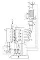
図1は、本発明に係る内燃機関の排気浄化装置を適用する内燃機関とその吸排気系の概略構成を示す図である。
図1に示す内燃機関1は、4つの気筒2aを有する4サイクルの水冷式ガソリンエンジンである。この内燃機関1には、各気筒2aの燃焼室に臨むよう点火栓2bが取り付けられている。
【0023】
前記内燃機関1には、吸気枝管3が接続され、前記吸気枝管3の各枝管は、図示しない吸気ポートを介して各気筒2aの燃焼室と連通している。
前記吸気枝管3は、サージタンク4に接続され、サージタンク4は、吸気管5を介してエアクリーナボックス6に接続されている。
【0024】
前記吸気管5には、図示しないアクセルペダルと連動して、前記吸気管5内を流れる吸気流量を調節するスロットル弁7が設けられている。スロットル弁7には、該スロットル弁7の開度に対応した電気信号を出力するスロットルポジションセンサ8が取り付けられている。
【0025】
前記吸気管5において前記スロットル弁7より上流の部位には、吸気管5内を流れる吸気の質量に対応した電気信号を出力するエアフローメータ9が取り付けられている。
【0026】
前記吸気枝管3の各枝管には、各気筒2aの吸気ポートに向けて燃料を噴射する燃料噴射弁11a、11b、11c、11d(以下、燃料噴射弁11と総称する)が取り付けられている。
【0027】
各燃料噴射弁11は、燃料分配管10と連通しており、燃料分配管10は、図示しない燃料ポンプと連通している。前記燃料ポンプから吐出された燃料は、前記燃料分配管10に供給され、次いで燃料分配管10から各燃料噴射弁11へ分配されるようになっている。
【0028】
各燃料噴射弁11は、電気配線を介して駆動回路12a、12b、12c、12d(以下、駆動回路12と総称する)と接続されており、前記駆動回路12から燃料噴射弁11へ駆動電力が印加されると、前記燃料噴射弁11が開弁して燃料を噴射するようになっている。
【0029】
一方、内燃機関1には、排気枝管13が接続され、排気枝管13の各枝管が図示しない排気ポートを介して各気筒2aの燃焼室と連通している。前記排気枝管13は、排気管14に接続され、排気管14は、下流にて図示しないマフラーに接続されている。
【0030】
前記排気管14の途中には、該排気管14内を流れる排気に含まれる有害ガス成分を浄化するための触媒機構15が設けられている。この触媒機構15は、筒状のケーシング15aと、このケーシング15aに内装された触媒本体15bとを備えている。
【0031】
前記触媒本体15bは、例えば、排気の流れ方向に沿う貫通孔を複数有するよう格子状に形成されたコージェライトからなるセラミック担体と、セラミック担体の表面にコーティングされた触媒層とを備え、前記触媒層が多数の細孔を有する多孔質のアルミナ(Al2O3)の表面に白金−ロジウム(Pt−Rh)系あるいはパラジウム−ロジウム(Pd−Rh)系の貴金属触媒物質を担持させて形成された三元触媒である。
【0032】
このように構成された触媒本体15bは、所定温度以上のときに活性し、該触媒本体15bに流入する排気の空燃比が所望の空燃比近傍にあると、排気に含まれる炭化水素(HC)及び一酸化炭素(CO)を排気中の酸素O2と反応させてH2O及びCO2へ酸化すると同時に、排気中のNOXを排気中のHC及びCOと反応させてH2O、CO2、N2へ還元する。
【0033】
前記排気管14において触媒機構15より上流の部位には、触媒機構15へ流入する排気の空燃比に対応した電気信号を出力する空燃比センサ16が設けられている。
【0034】
前記空燃比センサ16は、例えば、ジルコニア(ZrO2)を筒状に焼成した固体電解質部と、この固体電解質部の外面を覆う外側白金電極と、前記固体電解質部の内面を覆う内側白金電極とから形成され、前記電極間に電圧が印加された場合に、酸素イオンの移動に伴って排気ガス中の酸素濃度(理論空燃比よりもリッチ側のときは未燃ガス成分の濃度)に比例した値の電圧を出力するセンサである。
【0035】
次に、前記触媒機構15のケーシング15aにおいて触媒本体15bの直上流の部位には、圧電素子からなる着火装置17が設けられている。この着火装置17は、本発明に係る着火手段を実現するものである。
【0036】
前記触媒機構15の直上流に位置する排気管14には、本発明に係る火炎逆流防止手段としての逆火防止材18が設けられている。この逆火防止材18は、網目の径が消炎径以下となるよう形成された金網で構成されている。
【0037】
前記触媒機構15の下流に位置する排気管14には、該排気管14内を流れる排気の流量を絞る排気絞り弁19が設けられている。前記排気絞り弁19には、印加電力の大きさに応じて前記排気絞り弁19を開閉駆動するアクチュエータ20が取り付けられている。これら排気絞り弁19とアクチュエータ20は、本発明に係る排気絞り手段を実現するものである。
【0038】
一方、内燃機関1には、図示しないクランクシャフトの端部に取り付けられたタイミングロータと、内燃機関1のシリンダブロックに取り付けられた電磁ピックアップとから構成され、前記クランクシャフトが所定角度(例えば、30度)回転する都度、パルス信号を出力するクランクポジションセンサ21が取り付けられている。
【0039】
前記内燃機関1には、該内燃機関1のシリンダブロック及びシリンダヘッドに形成されたウォータジャケット内を流れる冷却水の温度に対応した電気信号を出力する水温センサ22が取り付けられている。
【0040】
このように構成された内燃機関1には、該内燃機関1を制御するための電子制御ユニット(ECU:Electronic Control Unit)23が併設されている。ECU23には、スロットルポジションセンサ8、エアフローメータ9、空燃比センサ16、クランクポジションセンサ21、水温センサ22等の各種センサが電気配線を介して接続され、各センサの出力信号がECU23に入力されるようになっている。
【0041】
前記ECU23には、点火栓2b、駆動回路12、着火装置17、アクチュエータ20等が電気配線を介して接続され、上記した各種センサの出力信号値をパラメータとして点火栓2b、駆動回路12、着火装置17、アクチュエータ20等を制御することが可能となっている。
【0042】
ここで、ECU23は、図2に示すように、双方向性バス24により相互に接続された、CPU25とROM26とRAM27とバックアップRAM28と入力ポート29と出力ポート31とを備えるとともに、前記入力ポート29に接続されたA/Dコンバータ(A/D)30を備えている。
【0043】
前記入力ポート29は、クランクポジションセンサ21のようにデジタル信号形式の信号を出力するセンサの出力信号を入力し、それらの出力信号をCPU25やRAM27へ送信する。
【0044】
前記入力ポート29は、スロットルポジションセンサ7、エアフローメータ9、空燃比センサ16、水温センサ22のように、アナログ信号形式の信号を出力するセンサの出力信号をA/Dコンバータ30を介して入力し、それらの出力信号をCPU25やRAM27へ送信する。
【0045】
前記出力ポート31は、点火栓2b、駆動回路12、着火装置17、アクチュエータ20等と電気配線を介して接続され、CPU25から出力される制御信号を、前記した点火栓2b、駆動回路12、着火装置17、あるいはアクチュエータ20等へ送信する。
【0046】
前記ROM26は、各点火栓2bの点火時期を決定するための点火時期制御ルーチン、各燃料噴射弁11から噴射すべき燃料噴射量を決定するための燃料噴射量制御ルーチン、燃料噴射量の空燃比フィードバック制御を行うための空燃比フィードバック制御ルーチン、各燃料噴射弁11の燃料噴射時期を決定するための燃料噴射時期制御ルーチン等の各種のアプリケーションプログラムに加え、触媒本体15bを加熱するための触媒加熱制御ルーチンを記憶している。
【0047】
更に、前記ROM26には、上記したようなアプリケーションプログラムに加え、各種の制御マップを記憶している。前記制御マップは、例えば、内燃機関1の運転状態と点火時期との関係を示す点火時期制御マップ、内燃機関1の運転状態と燃料噴射量との関係を示す燃料噴射量制御マップ、内燃機関1の運転状態と燃料噴射時期との関係を示す燃料噴射時期制御マップ等である。
【0048】
前記RAM27は、各センサからの出力信号やCPU25の演算結果等を格納する。前記演算結果は、例えば、クランクポジションセンサ21の出力信号より算出される機関回転数である。これらのデータは、クランクポジションセンサ21が信号を出力する都度、最新のデータに書き換えられる。
【0049】
前記バックアップRAM28は、内燃機関1の運転停止後もデータを記憶可能な不揮発性のメモリである。
前記CPU25は、前記ROM26に記憶されたアプリケーションプログラムに従って動作する。その際、CPU25は、RAM27に記憶された前記各センサの出力信号より内燃機関1の運転状態を判定し、その運転状態と各制御マップとから点火制御や燃料噴射制御等の各種制御を実行するとともに、本発明の要旨となる触媒加熱制御を実行する。
【0050】
触媒加熱制御は、触媒機構15の触媒本体15bを早期に活性するための制御であり、内燃機関1が冷間始動される場合のように、触媒本体15bが未活性状態にある状況下で内燃機関1が始動される場合に実行される。
【0051】
触媒加熱制御では、CPU25は、先ず、内燃機関1の始動時に触媒本体15bが活性状態にあるか否かを判別する。
CPU25は、触媒本体15bが未活性状態にあると判定した場合は触媒本体15bを早期に活性すべく触媒加熱処理を実行し、触媒本体15bが活性状態にあると判定した場合は触媒加熱処理を実行しないものとする。
【0052】
触媒加熱処理では、CPU25は、先ず、点火栓2bへの駆動電力の印加を禁止した上で、図示しないスターターモータを作動させるとともに、駆動回路12へ駆動電力を印加して燃料噴射弁11を作動させ、次いで着火装置17へ駆動電力を印加する。
【0053】
この場合、内燃機関1の各気筒2a内には、空気と燃料とが供給され、それらの空気と燃料とが混ざり合って可燃混合気を形成するが、点火栓2bが作動していないため、前記した可燃混合気は未燃状態のままで各気筒2aから排出されることになる。
【0054】
各気筒2bから排出された未燃状態の可燃混合気は、排気枝管13及び排気管14を経て触媒機構15に到達する。触媒機構15に到達した可燃混合気は、着火装置17によって着火され燃焼せしめられる。その際、着火装置17は、触媒本体15bの直上流に位置するため、可燃混合気の火炎が触媒本体15bを急速に加熱することになる。
【0055】
ところで、内燃機関1から排出される排気(この場合は可燃混合気)には排気脈動が伴うとともに、内燃機関1が冷間始動される時には排気管14及びケーシング15a内の雰囲気温度が低いため、単に内燃機関1から着火装置17へ可燃混合気を供給するだけでは、可燃混合気の着火性や燃焼の安定性が低下することが想定される。
【0056】
そこで、本実施の形態にかかる触媒加熱処理では、CPU25は、内燃機関1から着火装置17へ可燃混合気を供給する際に、排気絞り弁19を所定開度まで閉弁させるようにした。
【0057】
この場合、内燃機関1から排気絞り弁19に至る排気経路の圧力が上昇し、その上昇した圧力によって排気の脈動が抑制されるとともに排気経路内の温度が上昇する。
【0058】
この結果、可燃混合気の着火性や、可燃混合気の燃焼の安定性が向上する。更に、本実施の形態に係る排気浄化装置では、排気管14において触媒機構15より上流の部位に逆火防止材18が設けられているため、可燃混合気の燃焼時に発生する火炎が排気管14内を逆流することが無く、可燃混合気の燃焼がより一層安定することになる。
【0059】
上記したような触媒加熱処理は、所定時間継続される。前記所定時間は、触媒加熱処理によって触媒本体15bが活性温度まで昇温するのに要する時間であり、予め実験的に求められた時間である。
【0060】
尚、前記所定時間は、固定値でもよく、内燃機関1が始動される際の触媒本体15bの触媒床温に応じて変更される可変値であってもよい。
CPU25は、触媒加熱処理を所定時間継続した後は、内燃機関1から着火装置17に至る排気経路に残留している可燃混合気を一掃すべく、可燃混合気除去処理を所定期間実行する。
【0061】
可燃混合気除去処理では、CPU25は、例えば、点火栓2bに対する駆動電力の印加禁止に加え、駆動回路12に対する駆動電力の印加も禁止するとともに排気絞り弁19を全開状態に戻すべくアクチュエータ20を制御する。
【0062】
この場合、内燃機関1の各気筒2aには空気のみが供給されることになり、その空気が各気筒2a内から排出されることになる。各気筒2a内から排出された空気は、排気枝管13、排気管14、触媒機構15、及び排気管14を流れる。
【0063】
その際、排気絞り弁19が全開状態にあるため、各気筒2aから排出された空気は、排気枝管13、排気管14、触媒機構15、及び排気管14を勢い良く流れることになる。
【0064】
この結果、内燃機関1から触媒機構15に至る排気経路(排気枝管13、及び排気管14)内に残留していた可燃混合気は、該排気経路を勢い良く流れる空気によって触媒機構15へ導かれ、触媒加熱処理によって活性した触媒本体15bにて浄化される。
【0065】
このような可燃混合気除去処理が所定期間実行されると、CPU25は、点火栓2bに対する駆動電力の印加、及び駆動回路12に対する駆動電力の印加を開始して、内燃機関1を始動させる。その際、内燃機関1から触媒機構15に至る排気経路に残留していた可燃混合気が既に一掃されているため、内燃機関1の気筒2a内から触媒機構15に至る広い範囲において火炎が発生することがない。
【0066】
以下、本実施の形態における触媒加熱制御について具体的に説明する。
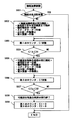
CPU25は、触媒加熱制御を実行するにあたり、図3に示すような触媒加熱制御ルーチンを実行する。
【0067】
触媒加熱制御ルーチンは、予めROM26に記憶されたルーチンであり、内燃機関1の始動時に実行されるルーチンである。
触媒加熱ルーチンでは、CPU26は、先ずS301において触媒本体15bが活性状態にあるか否か、言い換えれば触媒本体15bの触媒床温が所定の活性温度以上であるか否かを判別する。
【0068】
触媒本体15bが活性状態にあるか否かを判定する方法としては、内燃機関1が最後に運転停止された時点から今回始動される時点までの経過時間から触媒床温が活性温度未満まで低下したか否かを推定する方法、触媒本体15bに該触媒本体15bの触媒床温を検出する温度センサを取り付け、その温度センサの出力信号値が活性温度未満であるか否かを判定する方法などを例示することができる。
【0069】
前記S301において触媒本体15bが活性状態にあると判定した場合は、CPU25は、本ルーチンの実行を終了し、通常の始動制御を実行する。
一方、前記S301において触媒本体15bが未活性状態にあると判定した場合は、CPU25は、S302へ進み、触媒加熱処理の実行を開始する。具体的には、CPU25は、排気絞り弁19を所定開度まで閉弁させるべくアクチュエータ20を制御する。次いでCPU25は、スターターモータ、駆動回路12、及び着火装置17に対する駆動電力の印加を開始するとともに、点火栓2bに対する駆動電力の印加を禁止する。
【0070】
S303では、CPU25は、触媒加熱処理の実行時間を計時する第1のカウンタ:C1のカウンタ値を更新する。
S304では、CPU25は、前記S303において更新された第1のカウンタ:C1のカウンタ値が所定値:CS1以上であるか否か、すなわち、触媒加熱処理が所定時間以上実行されたか否かを判別する。
【0071】
前記S304において第1のカウンタ:C1のカウンタ値が所定値:CS1未満であると判定した場合は、CPU25は、前記S303以降の処理を再度実行する。
【0072】
一方、前記S304において第1のカウンタ:C1のカウンタ値が所定値:CS1以上であると判定した場合は、CPU25は、S305へ進み、可燃混合気除去処理の実行を開始する。具体的には、CPU25は、スターターモータの作動を継続しつつ、駆動回路12、点火栓2b、及び、着火装置17に対する駆動電力の印加を禁止するとともに、排気絞り弁19を全開状態に戻すべくアクチュエータ20を制御する。
【0073】
S306では、CPU25は、可燃混合気除去処理の実行時間を計時する第2のカウンタ:C2のカウンタ値を更新する。
S307では、CPU25は、前記S306において更新された第2のカウンタ:C2のカウンタ値が所定値:CS2以上であるか否か、すなわち、可燃混合気除去処理が所定時間以上実行されたか否かを判別する。
【0074】
前記S307において第2のカウンタ:C2のカウンタ値が所定値:CS2未満であると判定した場合は、CPU25は、前記S306以降の処理を繰り返し実行する。
【0075】
一方、前記S307において第2のカウンタ:C2のカウンタ値が所定値:CS2以上であると判定した場合は、CPU25は、S308へ進み、可燃混合気除去処理の実行を終了する。
【0076】
S309では、CPU25は、前記した第1及び第2のカウンタ:C1、C2のカウンタ値を“0”にリセットし、本ルーチンの実行を終了する。本ルーチンの実行を終了したCPU25は、通常の機関始動制御を実行する。
【0077】
上記したような触媒加熱制御ルーチンによれば、内燃機関1が冷間始動された場合のように、触媒本体15bが未活性状態にある状況下で内燃機関1が始動される場合に、排気絞り弁19によって排気管14内の流量を絞った上で、内燃機関1から着火装置17へ可燃混合気を供給することにより、内燃機関1から着火装置17に至る排気経路の圧力が上昇し、その上昇した圧力によって内燃機関1から排出される可燃混合気の脈動が抑制されるとともに着火装置17近傍の雰囲気温度が高まるため、可燃混合気の着火性が向上し、且つ可燃混合気の燃焼が安定する。
【0078】
更に、排気絞り弁19によって排気管14内の流量が絞られると、可燃混合気の燃焼ガスが触媒本体15bを通過する際の流速が低くなるため、燃焼ガスから触媒本体15bへの熱伝導効率が向上する。
【0079】
また、上記した触媒加熱制御ルーチンによれば、触媒本体15の加熱が完了した後の所定期間において内燃機関1から空気のみを排出させることにより、内燃機関1から着火装置17に至る排気経路に残留している可燃混合気を除去することができ、内燃機関1の始動開始に伴う気筒2a内の燃焼が開始された際に、内燃機関1の気筒2a内から着火装置17に至る広い範囲で火炎が発生することがない。
【0080】
【発明の効果】
本発明に係る内燃機関の排気浄化装置では、排気浄化触媒を急速に加熱すべく内燃機関から着火手段へ可燃混合気を供給する際に、排気絞り手段によって排気通路内の流量が絞られるため、内燃機関から着火手段に至る排気通路内の圧力が上昇し、その上昇した圧力によって内燃機関から排出される可燃混合気の脈動が抑制されることになる。
【0081】
従って、本発明によれば、内燃機関から供給された可燃混合気を燃焼させることによって排気浄化触媒を急速に加熱する排気浄化装置において、可燃混合気の着火性及び可燃混合気の燃焼の安定性を向上させることが可能となり、排気浄化触媒を確実に加熱することが可能となる。
【図面の簡単な説明】
【図1】 本発明に係る排気浄化装置を適用する内燃機関の概略構成を示す図
【図2】 ECUの内部構成を示すブロック図
【図3】 触媒加熱制御ルーチンを示すフローチャート図
【符号の説明】
1・・・・内燃機関
2a・・・気筒
2b・・・点火栓
11・・・燃料噴射弁
12・・・駆動回路
13・・・排気枝管
14・・・排気管
15・・・触媒機構
15a・・ケーシング
15b・・触媒本体
16・・・空燃比センサ
17・・・着火装置
18・・・逆火防止材
19・・・排気絞り弁
20・・・アクチュエータ
23・・・ECU[0001]
BACKGROUND OF THE INVENTION
The present invention relates to a technology for purifying exhaust gas from an internal combustion engine mounted on an automobile or the like, and more particularly to a technology for activating an exhaust gas purification catalyst provided in an exhaust passage of an internal combustion engine at an early stage.
[0002]
[Prior art]
In recent years, an internal combustion engine mounted on an automobile or the like has been required to sufficiently purify harmful gas components contained in exhaust gas and release it into the atmosphere. In response to such demands, a technology has been proposed in which an exhaust gas purification catalyst is provided in an exhaust passage of an internal combustion engine, and a harmful gas component contained in the exhaust gas is purified by the exhaust gas purification catalyst.
[0003]
Examples of the exhaust purification catalyst include a wide variety of exhaust purification catalysts such as a three-way catalyst, a storage reduction type NOx catalyst, a selective reduction type NOx catalyst, an oxidation catalyst, or an exhaust purification catalyst obtained by appropriately combining these exhaust purification catalysts. Has been developed.
[0004]
The exhaust purification catalyst described above is uniformly activated at a predetermined temperature or more and can remove harmful gas components in the exhaust gas, so that the temperature of the exhaust purification catalyst is predetermined as when the internal combustion engine is cold started. When the temperature is lower than the temperature, harmful gas components in the exhaust gas cannot be sufficiently purified.
[0005]
In particular, when the internal combustion engine is cold-started, the temperature in the cylinder is low and combustion of the air-fuel mixture tends to become unstable, so a relatively large amount of unburned fuel components are discharged. When is in an inactive state, a relatively large amount of unburned fuel components are released into the atmosphere without being purified.
[0006]
Therefore, when the internal combustion engine is cold started, it is important to activate the exhaust purification catalyst at an early stage to suppress the deterioration of exhaust emission at the start and immediately after the start. Conventionally, a catalyst heating burner for a spark ignition engine as described in JP-A-8-170525 has been proposed in response to such a demand.
[0007]
The catalyst heating burner for a spark ignition engine described in the publication includes an exhaust purification catalyst provided in an exhaust passage of the internal combustion engine, and a combustor provided in an exhaust passage upstream of the exhaust purification catalyst. When the engine is in a warm-up operation after being cold-started, half of the cylinders of the internal combustion engine are operated with a rich mixture to generate combustible gas, and at the same time, fuel injection to the remaining half of the cylinders is stopped, The exhaust purification catalyst is rapidly heated by mixing and burning the combustible gas discharged from the former half of the cylinder and the air discharged from the remaining half of the cylinder in the combustor.
[0008]
[Problems to be solved by the invention]
By the way, the catalyst heating burner for the spark ignition engine as described above is such that the combustible mixture in the combustor is easily affected by the exhaust pulsation, and the atmosphere temperature in the exhaust passage and the combustor is low. It is assumed that the combustion tends to become unstable and the amount of unburned fuel component released into the atmosphere increases.
[0009]
The present invention has been made in view of the above-described problems, and in an exhaust purification apparatus for combusting a combustible air-fuel mixture supplied from an internal combustion engine in an exhaust passage upstream of an exhaust purification catalyst, An object of the present invention is to provide a technique for stabilizing the combustion of a combustible air-fuel mixture so as to achieve early activation of an exhaust purification catalyst, thereby suppressing deterioration of exhaust emission when starting an internal combustion engine.
[0010]
[Means for Solving the Problems]
The present invention employs the following means in order to solve the above-described problems. That is, an exhaust gas purification apparatus for an internal combustion engine according to the present invention includes an exhaust passage connected to the internal combustion engine,
An exhaust purification catalyst that is provided in the middle of the exhaust passage and purifies exhaust flowing in the exhaust passage; Supply means for supplying a combustible air-fuel mixture from the internal combustion engine to the exhaust purification catalyst by prohibiting the operation of the spark plug and permitting the operation of the fuel injection valve during cranking of the internal combustion engine; Ignition means provided in a portion upstream of the exhaust purification catalyst in the exhaust passage, for igniting a combustible air-fuel mixture supplied from the internal combustion engine and heating the exhaust purification catalyst; ,in front An exhaust throttle that is provided in the exhaust passage and restricts the flow rate of the exhaust flowing through the exhaust passage when the exhaust purification catalyst is heated. Step and It is characterized by providing.
[0011]
In the exhaust gas purification apparatus for an internal combustion engine configured as described above, the combustible air-fuel mixture is supplied from the internal combustion engine to the ignition means when it is necessary to heat the exhaust gas purification catalyst as in the case where the internal combustion engine is cold started. In addition, the exhaust throttle means throttles the flow rate in the exhaust passage. Next, the ignition means ignites the combustible mixture supplied from the internal combustion engine to burn the combustible mixture.
[0012]
In this case, when the exhaust throttle means throttles the flow rate in the exhaust passage, the pressure in the exhaust passage from the internal combustion engine to the exhaust throttle means increases, and the pulsation of the exhaust discharged from the internal combustion engine is suppressed. As a result, the ignitability of the combustible mixture is improved and the combustion of the combustible mixture is stabilized.
[0013]
Here, as a method of supplying the combustible air-fuel mixture from the internal combustion engine to the exhaust purification catalyst, (1) when the internal combustion engine is cranked, the unburned combustible air-fuel mixture is discharged from each cylinder of the internal combustion engine to the ignition means. (2) Combusting an excess fuel (rich) air-fuel mixture in some cylinders of the internal combustion engine to discharge exhaust gas containing unburned fuel components from the cylinders and oxygen remaining in the remaining cylinders ( A method in which a mixture of lean gas is burned to discharge exhaust gas containing oxygen from the cylinder, and the exhaust gas is mixed in an exhaust passage and then supplied to ignition means, or (3) a part of an internal combustion engine A rich mixture is formed in the cylinders and a lean mixture (or only air) is formed in the remaining cylinders. The rich mixture and the lean mixture are discharged from the internal combustion engine in an unburned state, and the exhausts are exhausted. How such a supply to the ignition means on which is a mixture can be illustrated in the road.
[0014]
In the exhaust gas purification apparatus for an internal combustion engine according to the present invention, the exhaust throttle means is preferably provided in a portion downstream of the ignition means in the exhaust passage, preferably in a portion downstream of the exhaust purification catalyst in the exhaust passage.
[0015]
In this case, if the exhaust flow rate in the exhaust passage is reduced by the exhaust throttle means, the pressure in the exhaust passage rises and the exhaust pulsation is suppressed, and the ambient temperature in the vicinity of the ignition means rises. Qi ignitability will be further improved.
[0016]
Further, when the exhaust throttle means is located downstream of the exhaust purification catalyst in the exhaust passage, the exhaust throttle means throttles the exhaust flow rate in the exhaust passage, thereby increasing the pressure in the exhaust passage including the ignition means and the exhaust purification catalyst. In addition, the ignitability of the combustible air-fuel mixture is improved, and the combustion gas of the combustible air-fuel mixture flows through the exhaust purification catalyst at a low flow rate, thereby improving the heating performance of the exhaust purification catalyst by the combustible air-fuel mixture.
[0017]
Further, the exhaust gas purification apparatus for an internal combustion engine according to the present invention is provided in an exhaust passage upstream of the ignition means, and flame backflow prevention means for preventing the flame of the combustible mixture ignited by the ignition means from flowing back through the exhaust passage. May be further provided.
[0018]
In this case, since the flame of the combustible mixture ignited by the ignition means does not flow backward in the exhaust passage, the flame is stabilized and the exhaust purification catalyst can be reliably heated.
[0019]
Here, examples of the flame backflow prevention means include a wire mesh having a number of holes having a diameter equal to or less than the flame extinguishing diameter.
In addition, the exhaust gas purification apparatus for an internal combustion engine according to the present invention may further include air discharge means for discharging only air from the internal combustion engine during a predetermined period after the heating of the exhaust gas purification catalyst.
[0020]
In this case, only the air is discharged from the internal combustion engine for a predetermined period after the heating of the exhaust purification catalyst, and the combustible air-fuel mixture remaining in the exhaust passage from the internal combustion engine to the ignition means is wiped out. The combustible mixture does not burn in the exhaust passage from the internal combustion engine to the ignition means after the purification catalyst is heated.
[0021]
DETAILED DESCRIPTION OF THE INVENTION
Hereinafter, specific embodiments of an exhaust emission control device for an internal combustion engine according to the present invention will be described with reference to the drawings.
[0022]
FIG. 1 is a diagram showing a schematic configuration of an internal combustion engine to which the exhaust gas purification apparatus for an internal combustion engine according to the present invention is applied and its intake and exhaust system.
The
[0023]
An intake branch pipe 3 is connected to the
The intake branch pipe 3 is connected to a surge tank 4, and the surge tank 4 is connected to an air
[0024]
The intake pipe 5 is provided with a
[0025]
An
[0026]
[0027]
Each fuel injection valve 11 communicates with a
[0028]
Each fuel injection valve 11 is connected to drive
[0029]
On the other hand, an
[0030]
In the middle of the
[0031]
The
[0032]
The thus configured
[0033]
An air-
[0034]
The air-
[0035]
Next, in the
[0036]
The
[0037]
The
[0038]
On the other hand, the
[0039]
The
[0040]
The
[0041]
The
[0042]
Here, as shown in FIG. 2, the
[0043]
The
[0044]
The
[0045]
The
[0046]
The
[0047]
Furthermore, the
[0048]
The
[0049]
The
The
[0050]
The catalyst heating control is a control for activating the
[0051]
In the catalyst heating control, the
When the
[0052]
In the catalyst heating process, the
[0053]
In this case, air and fuel are supplied into each
[0054]
The unburned combustible mixture discharged from each
[0055]
By the way, the exhaust gas discharged from the internal combustion engine 1 (in this case, combustible mixture) is accompanied by exhaust pulsation, and when the
[0056]
Therefore, in the catalyst heating process according to the present embodiment, the
[0057]
In this case, the pressure in the exhaust path from the
[0058]
As a result, the ignitability of the combustible mixture and the stability of combustion of the combustible mixture are improved. Further, in the exhaust purification apparatus according to the present embodiment, the backfire
[0059]
The catalyst heat treatment as described above is continued for a predetermined time. The predetermined time is a time required for the
[0060]
The predetermined time may be a fixed value or a variable value that is changed according to the catalyst bed temperature of the
After continuing the catalyst heating process for a predetermined time, the
[0061]
In the combustible mixture removal process, for example, the
[0062]
In this case, only air is supplied to each
[0063]
At this time, since the
[0064]
As a result, the combustible air-fuel mixture remaining in the exhaust path (
[0065]
When such a combustible air-fuel mixture removal process is executed for a predetermined period, the
[0066]
Hereinafter, the catalyst heating control in the present embodiment will be specifically described.
In executing the catalyst heating control, the
[0067]
The catalyst heating control routine is a routine stored in the
In the catalyst heating routine, the
[0068]
As a method of determining whether or not the catalyst
[0069]
When it is determined in S301 that the catalyst
On the other hand, if it is determined in S301 that the
[0070]
In S303, the
In S304, the
[0071]
If it is determined in S304 that the counter value of the first counter: C1 is less than the predetermined value: CS1, the
[0072]
On the other hand, if it is determined in S304 that the counter value of the first counter: C1 is greater than or equal to the predetermined value: CS1, the
[0073]
In S306, the
In S307, the
[0074]
If it is determined in S307 that the counter value of the second counter: C2 is less than the predetermined value: CS2, the
[0075]
On the other hand, if it is determined in S307 that the counter value of the second counter: C2 is equal to or greater than the predetermined value: CS2, the
[0076]
In S309, the
[0077]
According to the catalyst heating control routine as described above, when the
[0078]
Further, when the flow rate in the
[0079]
Further, according to the above-described catalyst heating control routine, only air is discharged from the
[0080]
【The invention's effect】
In the exhaust gas purification apparatus for an internal combustion engine according to the present invention, when the combustible air-fuel mixture is supplied from the internal combustion engine to the ignition means to rapidly heat the exhaust purification catalyst, the flow rate in the exhaust passage is throttled by the exhaust throttle means. The pressure in the exhaust passage from the internal combustion engine to the ignition means increases, and the increased pressure suppresses the pulsation of the combustible air-fuel mixture discharged from the internal combustion engine.
[0081]
Therefore, according to the present invention, in an exhaust purification device that rapidly heats an exhaust purification catalyst by burning a combustible mixture supplied from an internal combustion engine, the ignitability of the combustible mixture and the combustion stability of the combustible mixture Thus, the exhaust purification catalyst can be reliably heated.
[Brief description of the drawings]
FIG. 1 is a diagram showing a schematic configuration of an internal combustion engine to which an exhaust gas purification apparatus according to the present invention is applied.
FIG. 2 is a block diagram showing the internal configuration of the ECU
FIG. 3 is a flowchart showing a catalyst heating control routine.
[Explanation of symbols]
1 ... Internal combustion engine
2a ... Cylinder
2b ... ignition plug
11 ... Fuel injection valve
12 ... Drive circuit
13 ... Exhaust branch pipe
14 ... Exhaust pipe
15 ... Catalyst mechanism
15a ... casing
15b ... Catalyst body
16 ... Air-fuel ratio sensor
17 ... Ignition device
18 ... Backfire prevention material
19 ... Exhaust throttle valve
20 ... Actuator
23 ... ECU
Claims (4)
前記排気通路の途中に設けられ、前記排気通路内を流れる排気を浄化する排気浄化触媒と、
前記内燃機関のクランキング時に点火栓の作動を禁止するとともに燃料噴射弁の作動を許容することにより、前記内燃機関から前記排気浄化触媒へ可燃混合気を供給する供給手段と、
前記排気通路において前記排気浄化触媒より上流の部位に設けられ、前記内燃機関から供給される可燃混合気に着火して前記排気浄化触媒を加熱する着火手段と、
前記排気通路に設けられ、前記排気浄化触媒の加熱時に前記排気通路内を流れる排気の流量を絞る排気絞り手段と、
を備えることを特徴とする内燃機関の排気浄化装置。An exhaust passage connected to the internal combustion engine;
An exhaust purification catalyst that is provided in the middle of the exhaust passage and purifies exhaust flowing in the exhaust passage ;
Supply means for supplying a combustible air-fuel mixture from the internal combustion engine to the exhaust purification catalyst by prohibiting the operation of a spark plug during cranking of the internal combustion engine and allowing the operation of a fuel injection valve;
Ignition means provided in a portion of the exhaust passage upstream of the exhaust purification catalyst and igniting a combustible air-fuel mixture supplied from the internal combustion engine to heat the exhaust purification catalyst ;
Wherein provided in an exhaust passage, an exhaust throttle hand stage throttling the flow rate of the exhaust gas flowing through the exhaust passage during heating of the exhaust gas purifying catalyst,
Exhaust purification system of an internal combustion engine, characterized in that it comprises a.
Priority Applications (6)
| Application Number | Priority Date | Filing Date | Title |
|---|---|---|---|
| JP30052899A JP4304789B2 (en) | 1999-10-22 | 1999-10-22 | Exhaust gas purification device for internal combustion engine |
| US09/690,392 US6481200B1 (en) | 1999-10-22 | 2000-10-17 | Catalyst warming apparatus of internal combustion engine |
| ES00122780T ES2201989T3 (en) | 1999-10-22 | 2000-10-19 | CATALYST HEATING EQUIPMENT OF AN INTERNAL COMBUSTION ENGINE. |
| DE60005109T DE60005109T2 (en) | 1999-10-22 | 2000-10-19 | Heating device of a catalyst of an internal combustion engine |
| EP00122780A EP1094205B1 (en) | 1999-10-22 | 2000-10-19 | Catalyst warming apparatus of internal combustion engine |
| US10/243,914 US20030014966A1 (en) | 1999-10-22 | 2002-09-16 | Catalyst warming apparatus of internal combustion engine |
Applications Claiming Priority (1)
| Application Number | Priority Date | Filing Date | Title |
|---|---|---|---|
| JP30052899A JP4304789B2 (en) | 1999-10-22 | 1999-10-22 | Exhaust gas purification device for internal combustion engine |
Publications (3)
| Publication Number | Publication Date |
|---|---|
| JP2001123825A JP2001123825A (en) | 2001-05-08 |
| JP2001123825A5 JP2001123825A5 (en) | 2006-08-10 |
| JP4304789B2 true JP4304789B2 (en) | 2009-07-29 |
Family
ID=17885915
Family Applications (1)
| Application Number | Title | Priority Date | Filing Date |
|---|---|---|---|
| JP30052899A Expired - Fee Related JP4304789B2 (en) | 1999-10-22 | 1999-10-22 | Exhaust gas purification device for internal combustion engine |
Country Status (1)
| Country | Link |
|---|---|
| JP (1) | JP4304789B2 (en) |
Families Citing this family (4)
| Publication number | Priority date | Publication date | Assignee | Title |
|---|---|---|---|---|
| NZ522619A (en) * | 2004-06-18 | 2005-08-26 | S | Hydrogen electrolysis with pyramid shaped reaction cell and moderated production rate |
| JP4749982B2 (en) * | 2006-09-14 | 2011-08-17 | ヤマハ発動機株式会社 | Motorcycle |
| US8544259B2 (en) | 2009-09-18 | 2013-10-01 | Toyota Jidosha Kabushiki Kaisha | Exhaust purification system of internal combustion engine |
| US11891935B1 (en) | 2023-05-24 | 2024-02-06 | Honda Motor Co., Ltd | Exhaust gas purification apparatus |
-
1999
- 1999-10-22 JP JP30052899A patent/JP4304789B2/en not_active Expired - Fee Related
Also Published As
| Publication number | Publication date |
|---|---|
| JP2001123825A (en) | 2001-05-08 |
Similar Documents
| Publication | Publication Date | Title |
|---|---|---|
| US6481200B1 (en) | Catalyst warming apparatus of internal combustion engine | |
| JP3684934B2 (en) | Exhaust gas purification device for internal combustion engine | |
| JP6579121B2 (en) | Control device for internal combustion engine | |
| EP1437503A2 (en) | Internal combustion engine | |
| JPH10299463A (en) | Exhaust emission control device for internal combustion engine | |
| JP3826642B2 (en) | Exhaust temperature raising device for internal combustion engine | |
| JP3932642B2 (en) | Exhaust gas purification device for lean combustion internal combustion engine | |
| JP4304789B2 (en) | Exhaust gas purification device for internal combustion engine | |
| JPH08296485A (en) | In-cylinder injection type internal combustion engine | |
| JP6248974B2 (en) | Control device for internal combustion engine | |
| JP3794179B2 (en) | Exhaust gas purification device for internal combustion engine | |
| JP3591403B2 (en) | Catalyst heating device for internal combustion engine | |
| JP2005002867A (en) | Exhaust emission control system of internal combustion engine | |
| JP2001115883A (en) | Exhaust gas temperature raising device for internal combustion engine | |
| JP2874480B2 (en) | Catalyst warm-up device for internal combustion engine | |
| JP2914045B2 (en) | Catalyst warm-up device for internal combustion engine | |
| JP3386008B2 (en) | Exhaust gas purification device for internal combustion engine | |
| JP4026371B2 (en) | Internal combustion engine having a combustion heater | |
| JP3552562B2 (en) | Exhaust gas purification device for internal combustion engine | |
| JP2996030B2 (en) | Catalyst warm-up device for internal combustion engine | |
| JP2001059428A (en) | Exhaust emission control device for internal combustion engine | |
| JP3620325B2 (en) | Internal combustion engine with combustion heater | |
| JP4192532B2 (en) | Exhaust gas purification device for internal combustion engine | |
| JP2004245182A (en) | Emission control device for internal combustion engine | |
| JP2010059873A (en) | Exhaust emission control device for internal combustion engine |
Legal Events
| Date | Code | Title | Description |
|---|---|---|---|
| A521 | Written amendment |
Free format text: JAPANESE INTERMEDIATE CODE: A523 Effective date: 20060628 |
|
| A621 | Written request for application examination |
Free format text: JAPANESE INTERMEDIATE CODE: A621 Effective date: 20060628 |
|
| A977 | Report on retrieval |
Free format text: JAPANESE INTERMEDIATE CODE: A971007 Effective date: 20090326 |
|
| TRDD | Decision of grant or rejection written | ||
| A01 | Written decision to grant a patent or to grant a registration (utility model) |
Free format text: JAPANESE INTERMEDIATE CODE: A01 Effective date: 20090407 |
|
| A01 | Written decision to grant a patent or to grant a registration (utility model) |
Free format text: JAPANESE INTERMEDIATE CODE: A01 |
|
| A61 | First payment of annual fees (during grant procedure) |
Free format text: JAPANESE INTERMEDIATE CODE: A61 Effective date: 20090420 |
|
| FPAY | Renewal fee payment (event date is renewal date of database) |
Free format text: PAYMENT UNTIL: 20120515 Year of fee payment: 3 |
|
| FPAY | Renewal fee payment (event date is renewal date of database) |
Free format text: PAYMENT UNTIL: 20120515 Year of fee payment: 3 |
|
| FPAY | Renewal fee payment (event date is renewal date of database) |
Free format text: PAYMENT UNTIL: 20130515 Year of fee payment: 4 |
|
| LAPS | Cancellation because of no payment of annual fees |