JP4301085B2 - Deterioration diagnosis system for heat source equipment - Google Patents
Deterioration diagnosis system for heat source equipment Download PDFInfo
- Publication number
- JP4301085B2 JP4301085B2 JP2004167899A JP2004167899A JP4301085B2 JP 4301085 B2 JP4301085 B2 JP 4301085B2 JP 2004167899 A JP2004167899 A JP 2004167899A JP 2004167899 A JP2004167899 A JP 2004167899A JP 4301085 B2 JP4301085 B2 JP 4301085B2
- Authority
- JP
- Japan
- Prior art keywords
- condenser
- heat transfer
- cooling water
- heat
- deterioration diagnosis
- Prior art date
- Legal status (The legal status is an assumption and is not a legal conclusion. Google has not performed a legal analysis and makes no representation as to the accuracy of the status listed.)
- Active
Links
Images


Classifications
-
- Y—GENERAL TAGGING OF NEW TECHNOLOGICAL DEVELOPMENTS; GENERAL TAGGING OF CROSS-SECTIONAL TECHNOLOGIES SPANNING OVER SEVERAL SECTIONS OF THE IPC; TECHNICAL SUBJECTS COVERED BY FORMER USPC CROSS-REFERENCE ART COLLECTIONS [XRACs] AND DIGESTS
- Y02—TECHNOLOGIES OR APPLICATIONS FOR MITIGATION OR ADAPTATION AGAINST CLIMATE CHANGE
- Y02A—TECHNOLOGIES FOR ADAPTATION TO CLIMATE CHANGE
- Y02A30/00—Adapting or protecting infrastructure or their operation
- Y02A30/27—Relating to heating, ventilation or air conditioning [HVAC] technologies
-
- Y—GENERAL TAGGING OF NEW TECHNOLOGICAL DEVELOPMENTS; GENERAL TAGGING OF CROSS-SECTIONAL TECHNOLOGIES SPANNING OVER SEVERAL SECTIONS OF THE IPC; TECHNICAL SUBJECTS COVERED BY FORMER USPC CROSS-REFERENCE ART COLLECTIONS [XRACs] AND DIGESTS
- Y02—TECHNOLOGIES OR APPLICATIONS FOR MITIGATION OR ADAPTATION AGAINST CLIMATE CHANGE
- Y02B—CLIMATE CHANGE MITIGATION TECHNOLOGIES RELATED TO BUILDINGS, e.g. HOUSING, HOUSE APPLIANCES OR RELATED END-USER APPLICATIONS
- Y02B30/00—Energy efficient heating, ventilation or air conditioning [HVAC]
- Y02B30/62—Absorption based systems
Landscapes
- Sorption Type Refrigeration Machines (AREA)
- Air Conditioning Control Device (AREA)
Description
本発明は、凝縮器に冷却水が通水されるターボ冷凍機や吸収冷温水機などの熱源機器およびその劣化診断システムに関し、特に伝熱管の汚れによる性能の劣化を診断する熱源機器の劣化診断システムに関するものである。 The present invention relates to a heat source device such as a turbo chiller or an absorption chiller / heater in which cooling water is passed through a condenser and a deterioration diagnosis system thereof, and more particularly to a deterioration diagnosis of a heat source device that diagnoses performance deterioration due to dirt on a heat transfer tube. It is about the system.
従来、熱源機器の一つである吸収式冷温水機の凝縮器の異常検出を行う異常検出装置として、凝縮器の平均温度差を計算する回路と、凝縮器の熱交換量を計算する回路と、凝縮器の異常度を計算する回路と、故障判定回路とを具えた演算装置を持つものがある(例えば、特許文献1参照)。 Conventionally, as an abnormality detection device for detecting an abnormality of a condenser of an absorption chiller / heater that is one of heat source devices, a circuit for calculating an average temperature difference of the condenser, and a circuit for calculating a heat exchange amount of the condenser Some have an arithmetic unit including a circuit for calculating the degree of abnormality of the condenser and a failure determination circuit (see, for example, Patent Document 1).
本従来技術では、凝縮器平均温度差計算回路において、冷却水中間温度センサーから得られる冷却水中間温度すなわち凝縮器の冷却水入口温度Tco_midと、冷却水出口温度センサーから得られる凝縮器の冷却水出口温度Tco_outと、凝縮冷媒温度センサーから得られる凝縮冷媒温度Tv_condから、下記の計算式によって凝縮器の平均温度差Tmを算出する。 In this prior art, in the condenser average temperature difference calculation circuit, the cooling water intermediate temperature obtained from the cooling water intermediate temperature sensor, that is, the cooling water inlet temperature Tco_mid of the condenser, and the cooling water of the condenser obtained from the cooling water outlet temperature sensor. The average temperature difference Tm of the condenser is calculated from the outlet temperature Tco_out and the condensed refrigerant temperature Tv_cond obtained from the condensed refrigerant temperature sensor by the following calculation formula.
Tm={(Tv_cond−Tco_mid)+(Tv_cond−Tco_out)}/2
また、凝縮器熱交換量計算回路では、冷却水中間温度センサーから得られる冷却水中間温度すなわち凝縮器の冷却水入口温度Tco_midと、冷却水出口温度センサーから得られる凝縮器の冷却水出口温度Tco_outと、冷却水流量センサーから得られる冷却水流量Vcoから、下記の計算式によって凝縮器熱交換量Qcondを算出する。
Tm = {(Tv_cond−Tco_mid) + (Tv_cond−Tco_out)} / 2
In the condenser heat exchange amount calculation circuit, the cooling water intermediate temperature obtained from the cooling water intermediate temperature sensor, that is, the cooling water inlet temperature Tco_mid of the condenser, and the cooling water outlet temperature Tco_out of the condenser obtained from the cooling water outlet temperature sensor. From the cooling water flow rate Vco obtained from the cooling water flow rate sensor, the condenser heat exchange amount Qcond is calculated by the following formula.
Qcond=Vco×(Tco_out−Tco_mid)
また、凝縮器異常度計算回路では、凝縮器平均温度差計算回路から得られる実際の凝縮器平均温度差Tmと、凝縮器熱交換量計算回路から得られる凝縮器熱交換量Qcondに基づいて、次式によって凝縮器の異常度Acondを算出する。
Qcond = Vco × (Tco_out−Tco_mid)
Further, in the condenser abnormality degree calculation circuit, based on the actual condenser average temperature difference Tm obtained from the condenser average temperature difference calculation circuit and the condenser heat exchange amount Qcond obtained from the condenser heat exchange amount calculation circuit, The condenser abnormality Acond is calculated by the following equation.
Acond=(Tm−Tmn)/Tmn
ここで、Tmnは正常運転時における理想的な平均温度差であり、予め凝縮器熱交換量Qcondとの関係でグラフ化され、或いはテーブル化されて、メモリに記憶されている。
Acond = (Tm−Tmn) / Tmn
Here, Tmn is an ideal average temperature difference during normal operation, and is previously graphed or tabled in relation to the condenser heat exchange amount Qcond and stored in the memory.
さらに、凝縮器異常度計算回路から得られる凝縮器異常度は故障判定回路へ供給されて、所定の評価基準と比較される。そして、故障判定回路は該比較結果に基づいて故障の程度を判定し、その結果を表示装置へ出力する。 Further, the condenser abnormality degree obtained from the condenser abnormality degree calculation circuit is supplied to the failure determination circuit and compared with a predetermined evaluation standard. Then, the failure determination circuit determines the degree of failure based on the comparison result and outputs the result to the display device.
従来の熱源機器の診断システムでは、上記特許文献1に記載されるように、熱源機に設置された各センサーからの計測値から算出される異常度によって故障の程度を判定していた。この場合、異常度の基礎となっている凝縮器平均温度差は、上記特許文献1にも記載されるように凝縮器熱交換量によって変化するために、正常時の値を用いた正規化を行って異常度を算出しているが、この異常度が凝縮器熱交換量の影響を受けて、劣化の度合が同じ場合であっても凝縮器熱交換量によって異なる値となるという課題があった。
In the conventional heat source equipment diagnosis system, as described in
また上記従来技術では、診断用の基準値として正常運転時における理想的な平均温度差を用いているが、この基準は正常運転時の定義及び算出方法に依存するために、機器仕様、運転条件などの、劣化以外の因子の影響が大きく、取扱いが難しいという課題があった。特に、劣化の主要因である伝熱管の汚れとの対応付けの手順が複雑かつ不明確である。 In the above prior art, an ideal average temperature difference during normal operation is used as a reference value for diagnosis, but this standard depends on the definition and calculation method during normal operation. There was a problem that it was difficult to handle due to the large influence of factors other than deterioration. In particular, the procedure for associating with heat transfer tube contamination, which is the main cause of deterioration, is complicated and unclear.
さらに上記従来技術では、基準値である理想的な平均温度差が凝縮器熱交換量との関係で記憶されており、冷却水の流量を制御して省エネルギーを図る冷却水変流量システムを導入した場合は考慮されていない。この場合、冷却水の流量が減少すると、伝熱管内の冷却水流速および管内熱伝達率が低下するために正常であるにもかかわらず異常度が増加するという課題があった。 Furthermore, in the above-mentioned prior art, an ideal average temperature difference that is a reference value is stored in relation to the amount of heat exchange of the condenser, and a cooling water variable flow rate system is introduced that controls the flow rate of cooling water to save energy. The case is not considered. In this case, when the flow rate of the cooling water is decreased, the cooling water flow rate in the heat transfer tube and the heat transfer coefficient in the tube are decreased, and thus there is a problem that the degree of abnormality increases despite being normal.
さらに上記従来技術では、熱源機器本体と異常検出装置との接続形態については触れていないが、産業的に利用、運用する際にはこの点が重要である。
本発明の目的は、上記課題を解決し、凝縮器熱交換量のや機種の違い、及び冷却水流量が変動するシステムに対応し、劣化の主要因である伝熱管の汚れに直接対応した使い勝手の良い評価指標およびその算出方法を具えた熱源機器の劣化診断システム、さらにこのシステムの、産業に利用し易い実用的な運用形態を提供することにある。
Furthermore, in the above-described conventional technology, the connection form between the heat source device main body and the abnormality detection device is not mentioned, but this point is important when industrially used and operated.
The object of the present invention is to solve the above-mentioned problems, to cope with a system in which the heat exchange amount of the condenser, the difference in the model, and the flow rate of the cooling water fluctuate, and the usability that directly copes with the contamination of the heat transfer tube which is the main cause of deterioration. It is an object of the present invention to provide a deterioration diagnosis system for a heat source device having a good evaluation index and a method for calculating the same, and a practical operational form of this system that is easy to use in industry.
上記目的を達成するために本発明に係る熱源機器の劣化診断システムでは、診断用の基礎データとして各センサーからの計測値に加えて、凝縮器の伝熱面積や冷却水の流路断面積などの機器の形状データを用いることによって、熱通過率、管内熱伝達率、汚れ係数などの劣化現象に直結した劣化診断指標を算出して診断を行い、その中で冷却水流量によって変動する管内熱伝達率も考慮したものである。また、診断を行う監視センタを情報通信ネットワークを介して複数の熱源機に接続したものとなっている。 In order to achieve the above object, in the heat source equipment deterioration diagnosis system according to the present invention, in addition to the measured values from each sensor as basic data for diagnosis, the heat transfer area of the condenser, the flow passage cross-sectional area of the cooling water, etc. By using the shape data of the equipment, the diagnosis is performed by calculating the deterioration diagnosis index directly related to the deterioration phenomenon such as heat transfer rate, heat transfer coefficient in the pipe, dirt coefficient, etc. The transmission rate is also taken into consideration. In addition, a monitoring center that performs diagnosis is connected to a plurality of heat source devices via an information communication network.
本発明によって、実際の劣化に直接関連した物理量である凝縮器の熱通過率、管内熱伝達率、汚れ係数を用いた劣化診断が可能となり、熱源機全体の性能低下との関連付けが明確になる。例えば、伝熱管の洗浄によって汚れを取り除いた場合に性能がどの程度回復するかを容易に予測することができ、伝熱管の洗浄を含むメンテナンスの時期や内容を適確に設定し、計画的、経済的に行うことが可能となる。 The present invention makes it possible to perform deterioration diagnosis using the heat transfer rate of the condenser, which is a physical quantity directly related to the actual deterioration, the heat transfer coefficient in the pipe, and the contamination coefficient, and the correlation with the deterioration in the performance of the entire heat source device becomes clear. . For example, it is possible to easily predict how much the performance will recover when the dirt is removed by cleaning the heat transfer tubes, setting the time and contents of maintenance including cleaning of the heat transfer tubes appropriately, systematically, It can be done economically.
さらに本発明によれば、熱源機器の凝縮器に通水される冷却水の流量が変動する場合においても、この影響を排除して伝熱管の汚れ係数を算出するので、冷却水変流量システムを導入した場合にも好適な劣化診断システムが得られる。さらには、情報通信ネットワークの利用によって複数の熱源機器を集中的に管理することによって、劣化診断システムの効率的な運用が可能となる。 Furthermore, according to the present invention, even when the flow rate of the cooling water flowing through the condenser of the heat source device fluctuates, the contamination coefficient of the heat transfer tube is calculated by eliminating this effect. Even when introduced, a suitable deterioration diagnosis system can be obtained. Furthermore, the deterioration diagnosis system can be efficiently operated by centrally managing a plurality of heat source devices by using the information communication network.
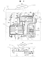
本発明の一実施例を図1、図2、図3を用いて説明する。図1は本発明による熱源機器の劣化診断システムの全体図である。また、図2は本発明による劣化診断システムの熱源機器部分の計測系統を、蒸気焚吸収式冷凍機(a)とターボ冷凍機(b)のそれぞれについて示した図である。さらに、図3は本発明による劣化診断システムの診断装置のブロック図である。 An embodiment of the present invention will be described with reference to FIGS. FIG. 1 is an overall view of a deterioration diagnosis system for heat source equipment according to the present invention. FIG. 2 is a diagram showing the measurement system of the heat source equipment portion of the deterioration diagnosis system according to the present invention for each of the steam soak absorption type refrigerator (a) and the turbo refrigerator (b). Further, FIG. 3 is a block diagram of a diagnostic apparatus of the degradation diagnostic system according to the present invention.
図1に示すように劣化診断システムは、各サイトに設けられた診断対象である熱源機1、熱源機2、……、熱源機nにそれぞれ設けられたデータ収録部1a、2a、……、naと、これらのデータ収録部と接続された情報通信ネットワーク100と、この情報通信ネットワーク100に接続された劣化診断装置200とによって構成する。
As shown in FIG. 1, the deterioration diagnosis system includes a
図2(a)に熱源機が蒸気焚吸収冷温水機である場合の、熱源機本体とデータ収録部との信号線の接続図を示す。吸収冷温水機は、一般的な構成要件である高温再生器31、低温再生器32、凝縮器33、蒸発器34、吸収器35、低温熱交換器36、高温熱交換器37、ドレンクーラ38などから構成されている。なお本実施例では冷却水の通水方法として、冷却水をまず吸収器35の一部に通水し、次に凝縮器に通水した後に吸収器の残りの部分に通水する方式としている。
FIG. 2 (a) shows a connection diagram of signal lines between the heat source unit main body and the data recording unit when the heat source unit is a steam tank absorption chiller / heater. The absorption chiller / heater includes general high-temperature regenerator 31, low-temperature regenerator 32, condenser 33,
データ収録部1aには、伝熱管の汚れを検出するための計測値として、凝縮器への冷却水入口温度33a、凝縮器からの冷却水出口温度33b、凝縮器内の冷媒蒸気圧力33c、凝縮器および吸収器内に通水される冷却水の流量33dの計測信号が入力されている。その他、熱源機全体の性能を診断するための計測値として、吸収冷温水機に供給される冷却水の温度35a、吸収冷温水機から図示しない冷却塔に送られる冷却水の温度35b、蒸発器への冷水入口温度34a、冷水出口温度34b、冷水流量34d、高温再生器31に供給される熱源蒸気の入口圧力31a、高温再生器からドレンクーラ38に向かうドレン温度31b、ドレン流量38dなどが入力され、記憶されている。
In the data recording unit 1a, as measured values for detecting contamination of the heat transfer tube, the cooling
次に、熱源機がターボ冷凍機である場合の熱源機本体とデータ収録部との信号線の接続図を図2(b)に示す。ターボ冷凍機は、圧縮機71、凝縮器33、蒸発器などから構成されており、データ収録部2aが設置されている。冷却水は冷却水入口配管82から凝縮器に供給され、冷却水出口配管81で凝縮器から排出されている。 Next, FIG. 2B shows a connection diagram of signal lines between the heat source unit main body and the data recording unit when the heat source unit is a turbo refrigerator. The turbo refrigerator includes a compressor 71, a condenser 33, an evaporator, and the like, and a data recording unit 2a is installed. The cooling water is supplied to the condenser from the cooling water inlet pipe 82 and is discharged from the condenser through the cooling water outlet pipe 81.
データ収録部2aには、伝熱管の汚れを検出するための計測値として、凝縮器への冷却水入口温度33a、凝縮器からの冷却水出口温度33b、凝縮器内の冷媒蒸気圧力33c、凝縮器に通水される冷却水流量33dの計測信号が入力されている。
In the data recording unit 2a, as measured values for detecting contamination of the heat transfer tube, the cooling
これらの熱源機の計測値は情報通信ネットワーク100を介して図1に示す劣化診断装置200に送信される。劣化診断装置200は、演算部210、記憶部250、表示部290などを有しており、記憶部250内には熱源機仕様データベース251(形状データ、伝熱特性等の各種仕様データを記憶)、劣化履歴データベース261が記憶されている。図3は演算部210における演算内容を示したブロック図である。以下、熱源機1を例として演算部210における伝熱管汚れの劣化診断方法について詳細に説明する。
The measured values of these heat source machines are transmitted to the
演算部200では、熱源機1に設けられたデータ収録部1aから情報通信ネットワーク100を介して送信された凝縮器冷却水入口温度TwCi、凝縮器冷却水出口温度TwCo、凝縮器圧力pC、凝縮器冷却水流量GwCと、図1の記憶部250の熱源機仕様データベース251に記憶された凝縮器伝熱面積AC、凝縮熱伝達率αCo、凝縮器冷却水流路断面積SwCなどの機器データ、冷媒と冷却水の物性値から、以下に示す手順で伝熱管汚れの劣化を診断する。
In the
まず、凝縮器圧力pCから、熱源機1で用いている冷媒の熱物性値の計算式数1によって冷媒凝縮温度TCを計算する。
First, the refrigerant condensing temperature TC is calculated from the condenser pressure pC by the

数1の関数ftは冷媒の種類によって決定し、例えば水を冷媒とする吸収式冷凍機に対しては、蒸気表などに記載されている水蒸気の圧力と平衡温度との関係式を用いる。
The function ft of
次に、数1によって算出したTCと、凝縮器冷却水入口温度TwCi、凝縮器冷却水出口温度TwCoから、凝縮器の平均熱交換温度差ΔTCを数2によって求める。
Next, the average heat exchange temperature difference ΔTC of the condenser is obtained by
なお、次の数3によって、対数平均温度差ΔLTCを求めてもよい。 The logarithmic average temperature difference ΔLTC may be obtained by the following equation (3).
次に、凝縮器冷却水入口温度TwCi、凝縮器冷却水出口温度TwCoと、凝縮器冷却水流量GwCから、凝縮器交換熱量QCを、次の数4によって算出する。 Next, the condenser exchange heat quantity QC is calculated by the following equation 4 from the condenser cooling water inlet temperature TwCi, the condenser cooling water outlet temperature TwCo, and the condenser cooling water flow rate GwC.
ここでcpwCは冷却水の比熱容量であり、一定値として記憶部250内の熱源機仕様データベース251に記憶しているものである。なお、この比熱容量は、凝縮器冷却水入口温度TwCi、または凝縮器冷却水出口温度TwCo、あるいはこれらの平均値などから、水の物性値を表す数5用いて算出してもよい。
Here, cpwC is the specific heat capacity of the cooling water, and is stored in the heat source unit specification database 251 in the storage unit 250 as a constant value. Note that this specific heat capacity may be calculated from the condenser cooling water inlet temperature TwCi, the condenser cooling water outlet temperature TwCo, or an average value of these, using
数5は冷却水すなわち水の比熱容量を温度から求める関数である。
以上の計算手順は前記特許文献1に記載のものと共通である。本実施例では、さらに数2によって算出した凝縮器の平均熱交換温度差ΔTC、数4によって算出した凝縮器交換熱量QCと、熱源機仕様データベース251に記憶された凝縮器伝熱面積ACから、凝縮器熱通過率KCを、次の数6によって求める。
The above calculation procedure is the same as that described in
なお凝縮器伝熱面積ACは、管群式の凝縮器を用いている場合は伝熱管の管外、管内どちらの面積を用いてもよい。本実施例では管外面積を用いるものとし、凝縮器の伝熱管群の管外総面積をACoで表す。 The condenser heat transfer area AC may be the area outside or inside the heat transfer tube when a tube group type condenser is used. In this embodiment, the area outside the tube is used, and the total area outside the tube of the heat transfer tube group of the condenser is represented by ACo.
次に、数6で算出した凝縮器熱通過率KCと、熱源機仕様データベース251に記憶された凝縮熱伝達率αCo、凝縮器の伝熱管群の管外総面積をACiから、凝縮器管内熱伝達率αCiを次の数7によって求める。 Next, the condenser heat passage rate KC calculated in Equation 6, the condensation heat transfer coefficient αCo stored in the heat source unit specification database 251, the total outside area of the condenser heat transfer tube group from ACi, and the condenser tube heat The transmission rate αCi is obtained by the following equation (7).
次に、伝熱管の汚れ係数の計算に移る。まず、凝縮器冷却水流量GwCと、熱源機仕様データベース251に記憶された凝縮器冷却水流路断面積SwCから、凝縮器冷却水管内流速vwCを次の数8によって求める。 Next, it shifts to the calculation of the fouling coefficient of the heat transfer tube. First, the condenser cooling water pipe flow velocity vwC is obtained from the condenser cooling water flow rate GwC and the condenser cooling water flow passage sectional area SwC stored in the heat source device specification database 251 by the following equation (8).
ここでρwCは冷却水の密度であり、一定値として記憶部250内に記憶しているものである。なお、この密度は、凝縮器冷却水入口温度TwCi、または凝縮器冷却水出口温度TwCo、あるいはこれらの平均値などから、水の物性値を表す数9用いて算出してもよい。 Here, ρwC is the density of the cooling water, and is stored in the storage unit 250 as a constant value. Note that this density may be calculated from the condenser cooling water inlet temperature TwCi, the condenser cooling water outlet temperature TwCo, or an average value of these using Equation 9 representing the physical property value of water.
数9は冷却水すなわち水の密度を温度から求める関数である。 Equation 9 is a function for determining the density of the cooling water, that is, the water from the temperature.
次に、数8で算出した凝縮器冷却水管内流速vwCと、熱源機仕様データベース251に記憶された凝縮器冷却水伝熱管内径dCiを用いて、凝縮器理想管内熱伝達率αCiiを次の数10によって求める。
Next, using the condenser cooling water pipe flow velocity vwC calculated in
数10において、NuwCは凝縮器の管内を流れる冷却水の平均ヌセルト数であり、本実施例では一般的に用いられているディタスーベルターの式によって凝縮器冷却水管内流速vwCから求める。また、λwCは冷却水の熱伝導率であり、冷却水の温度から物性値の式を用いて求める。
In
さらに、数7で算出した凝縮器管内熱伝達率αCiと、数10で算出した凝縮器理想管内熱伝達率αCiiから、凝縮器管内汚れ係数rCiを次の数11によって求める。
Further, the condenser pipe fouling coefficient rCi is calculated by the following
診断装置200の記憶部250には、数10によって算出された凝縮器管内汚れ係数rCi、数7によって算出された凝縮器管内熱伝達率αCi、数6で算出された凝縮器熱通過率KCが、劣化履歴データベース261として経時的に記憶されている。
In the storage unit 250 of the
これらの値は月単位の平均値として記憶されており、診断装置200の表示部290を操作することによって数値表示あるいは図1の299に示すようなトレンド表示として表示される。この表示結果を用いて診断を行う。
These values are stored as average values for each month, and are displayed as numerical values or as a trend display as shown by 299 in FIG. 1 by operating the
また、トレンド表示例299に示したような時系列データを一次式などの関数で近似してその後の劣化の進行を予測し、その結果に基づいて伝熱管の洗浄や冷却水の水質管理などの、保守の計画を行うこともできる。 In addition, time series data as shown in trend display example 299 is approximated by a function such as a linear expression to predict the progress of subsequent deterioration, and based on the result, heat transfer tube cleaning, cooling water quality management, etc. You can also plan for maintenance.
上記の記載は、数式の解法による劣化判断を述べているが、これを図3に当てはめて説明する。 The above description describes deterioration judgment by solving the mathematical formula, and this will be described with reference to FIG.
先ず、計測した凝縮器圧力33cを用いて数1により冷媒凝縮温度TCを求める。次に、凝縮器冷却水入口温度33aと凝縮器冷却水出口温度33bとの計測値、及び冷媒凝縮温度TCを用いて数2により凝縮器熱交換温度差ΔTCを求める。また、凝縮器冷却水入口温度33aと凝縮器冷却水出口温度33b及び冷却水流量33dとを用いて数4により凝縮器交換熱量QCを求める。次に、凝縮器熱交換温度差ΔTCと凝縮器交換熱量QC及び凝縮器伝熱面積ACとを用いて凝縮器熱通過率KCを数6により求める。また、凝縮熱伝達率αC0等と、凝縮器熱通過率KCを用いて数7により、凝縮器管内熱伝達率αCiを求める。
First, the refrigerant condensing temperature TC is obtained by
次に、冷却水流量33dと凝縮器冷却水流路断面積SwCとから凝縮器冷却水管内流速vwCを数8により求める。この凝縮器冷却水管内流速vwCと本図には図示していない凝縮器冷却水伝熱管内径dCiとから凝縮器管内理想熱伝達率αCiiを数10により求める。次に、凝縮管内熱伝達率αCiと凝縮器管内理想熱伝達率αCiiとを用いて数11により凝縮器管内汚れ係数rCiを求める。そして、劣化履歴データベース261に凝縮器管内汚れ係数、凝縮器管内熱伝達率、凝縮器熱通過率が時系列的に記憶され、この結果が表示部に時系列的に表示される。また、凝縮器管内汚れ係数等が所定の基準値を越えているか否かを判断し(チューブ汚れ診断)、基準値を越えている場合は管内の洗浄等を行うように報知する。また、凝縮器管内汚れ係数の変化の度合いを求めて、劣化の進行を予測して、保守計画等を立案できるようにしてある。
Next, the condenser cooling water pipe flow velocity vwC is obtained by the following equation (8) from the cooling
以上説明したように本実施例においては、熱源機器の劣化の代表的要因である冷却水系統の伝熱管汚れに対して、実際の現象を直接反映し、かつ熱源機の性能劣化との関係が明らかな、凝縮器管内汚れ係数rCi、凝縮器管内熱伝達率αCiを用いて診断を行うので、熱交換温度差と熱交換量から診断する従来技術と比較して、診断結果と熱源機の性能劣化との関係、伝熱管洗浄時の性能回復効果の予測が容易にかつ精度よく行うことができる。 As described above, in the present embodiment, the actual phenomenon is directly reflected on the heat transfer pipe contamination of the cooling water system, which is a representative factor of the deterioration of the heat source equipment, and there is a relationship with the performance deterioration of the heat source apparatus. Diagnosis is made using the obvious fouling coefficient rCi in the condenser tube and heat transfer coefficient αCi in the condenser pipe. Compared with the conventional technology that diagnoses from the heat exchange temperature difference and the heat exchange amount, the diagnosis result and the performance of the heat source machine It is possible to easily and accurately predict the relationship with deterioration and the performance recovery effect during heat transfer tube cleaning.
さらに本実施例においては、診断装置200の記憶部250内に熱源機仕様データベース251を具えているので、様々な熱源機の機種ごとに、当該機種の形状データから凝縮器熱通過率KC、凝縮器管内熱伝達率αCi、凝縮器管内汚れ係数rCiを算出することができる。
Furthermore, in the present embodiment, the heat source unit specification database 251 is provided in the storage unit 250 of the
さらに本実施例においては、冷却水流量33dを流量計を用いて実測しているので、稼動時の冷却水流量が熱源機の定格流量と異なる場合や冷却水変流量システムを採用した場合においても、凝縮器交換熱量QCと凝縮器管内流速vwCを実測値から算出して診断を行うことが可能である。
Furthermore, in the present embodiment, the cooling
さらに本実施例においては、複数の熱源機器1、2、……nと診断装置200を情報通信ネットワーク100で接続しているので、データの管理を一元的、容易に行うことができ、熱源機仕様データベースを診断装置200に具えることによって、熱源機の内部形状に係わる機密データの漏洩を防止することができる。
Further, in the present embodiment, since the plurality of
1…熱源機(蒸気焚吸収式冷凍機)、2…熱源機(ターボ冷凍機)、3、4、……、n…熱源機、1a、2a、……、na…データ収録部、31…高温再生器、32…低温再生器、33…凝縮器、34…蒸発器、35…吸収器、36…低温熱交換器、37…高温熱交換器、38…ドレンクーラ、71…圧縮機、81…冷却水入口配管、82…冷却水出口配管、100…情報通信ネットワーク、200…劣化診断装置、210…演算部、250…記憶部、251…熱源機仕様データベース、261…熱源機劣化履歴データベース、290…表示部、299…表示例、31a…熱源蒸気圧力、31b…高温再生器熱源ドレン出口温度、33a…凝縮器冷却水入口温度、33b…凝縮器冷却水出口温度、33c…凝縮器圧力、33d…凝縮器冷却水流量、34a…蒸発器(熱源機)冷水入口温度、34b…蒸発器(熱源機)冷水出口温度、34d…冷水流量、35a…熱源機冷却水入口温度、35b…熱源機冷却水出口温度、38b…ドレンクーラドレン出口温度、38d…ドレン流量。
DESCRIPTION OF
Claims (3)
前記凝縮器の冷却水流量検出手段を備え、前記劣化診断装置の前記熱通過率計算手段は、前記各検出手段によって検出された凝縮器の冷却水入口温度、凝縮器の冷却水出口温度、冷媒凝縮温度、冷却水流量および前記記憶部に記憶された形状データから前記凝縮器の熱通過率を算出し、
前記劣化診断装置は、前記記億部に凝縮熱伝達率を記憶すると共に、前記熱通過率計算手段によって算出された熱通過率、前記凝縮器の形状データ、前記凝縮熱伝達率から前記凝縮器の管内熱伝達率を算出する管内熱伝達率計算手段と、前記各検出手段によって検出された凝縮器の冷却水入口温度または凝縮器の冷却水出口温度、冷却水流量、および前記記憶部に記憶された形状データから前記凝縮器の理想管内熱伝達率を算出する理想管内熱伝達率計算手段と、前記管内熱伝達率と前記理想管内熱伝達率から凝縮器の伝熱管汚れ係数を算出する伝熱管汚れ係数計算手段と、を有することを特徴とする熱源機器の劣化診断システム。 In a deterioration diagnosis system for a heat source device for detecting contamination of a heat transfer tube of a heat source device to which cooling water is supplied from the outside, a cooling water inlet temperature detection means for a condenser through which the cooling water of the heat source device is passed, and A cooling water outlet temperature detecting means for the condenser, a refrigerant condensing temperature detecting means for the condenser, and a deterioration diagnosis device for detecting dirt in the heat transfer tube of the condenser, wherein the deterioration diagnosis device includes the condenser A storage unit that stores the shape data of the condenser, and the condenser cooling water inlet temperature, the condenser cooling water outlet temperature, the refrigerant condensing temperature detected by each of the detecting means, and the shape data stored in the storage unit A heat transfer rate calculating means for calculating the heat transfer rate of the vessel ,
The cooling water flow rate detecting means of the condenser is provided, and the heat passage rate calculating means of the deterioration diagnosis device is such that the cooling water inlet temperature of the condenser, the cooling water outlet temperature of the condenser detected by each of the detecting means, and the refrigerant Calculate the heat transfer rate of the condenser from the condensation temperature, the cooling water flow rate and the shape data stored in the storage unit,
The deterioration diagnosis device stores the condensation heat transfer coefficient in the storage part, and also calculates the condenser from the heat transfer rate calculated by the heat transfer rate calculation means, the shape data of the condenser, and the condensation heat transfer rate. The heat transfer coefficient calculation means for calculating the heat transfer coefficient in the pipe, the cooling water inlet temperature of the condenser or the cooling water outlet temperature of the condenser detected by each of the detection means, the cooling water flow rate, and the storage in the storage unit An ideal pipe heat transfer coefficient calculating means for calculating the ideal pipe heat transfer coefficient of the condenser from the obtained shape data, and a heat transfer pipe fouling coefficient of the condenser from the pipe heat transfer coefficient and the ideal pipe heat transfer coefficient. A deterioration diagnosis system for heat source equipment , comprising: a heat pipe contamination coefficient calculation means .
Priority Applications (1)
| Application Number | Priority Date | Filing Date | Title |
|---|---|---|---|
| JP2004167899A JP4301085B2 (en) | 2004-06-07 | 2004-06-07 | Deterioration diagnosis system for heat source equipment |
Applications Claiming Priority (1)
| Application Number | Priority Date | Filing Date | Title |
|---|---|---|---|
| JP2004167899A JP4301085B2 (en) | 2004-06-07 | 2004-06-07 | Deterioration diagnosis system for heat source equipment |
Publications (3)
| Publication Number | Publication Date |
|---|---|
| JP2005345046A JP2005345046A (en) | 2005-12-15 |
| JP2005345046A5 JP2005345046A5 (en) | 2006-08-10 |
| JP4301085B2 true JP4301085B2 (en) | 2009-07-22 |
Family
ID=35497598
Family Applications (1)
| Application Number | Title | Priority Date | Filing Date |
|---|---|---|---|
| JP2004167899A Active JP4301085B2 (en) | 2004-06-07 | 2004-06-07 | Deterioration diagnosis system for heat source equipment |
Country Status (1)
| Country | Link |
|---|---|
| JP (1) | JP4301085B2 (en) |
Cited By (1)
| Publication number | Priority date | Publication date | Assignee | Title |
|---|---|---|---|---|
| EP4328528A1 (en) * | 2022-08-24 | 2024-02-28 | LG Electronics, Inc. | Chiller including heat transfer tube and method for controlling chiller to determine degree of contamination of the heat transfer tube |
Families Citing this family (13)
| Publication number | Priority date | Publication date | Assignee | Title |
|---|---|---|---|---|
| JP4966921B2 (en) * | 2008-07-03 | 2012-07-04 | 株式会社日立製作所 | Deterioration diagnosis apparatus, deterioration diagnosis method, and deterioration diagnosis system for cooling / heating supply system |
| JP5078817B2 (en) * | 2008-09-12 | 2012-11-21 | 三菱電機株式会社 | Refrigeration cycle equipment |
| JP2010127568A (en) * | 2008-11-28 | 2010-06-10 | Mitsubishi Electric Corp | Abnormality detection device and refrigerating cycle device including the same |
| JP5642448B2 (en) * | 2010-08-02 | 2014-12-17 | 三菱重工業株式会社 | Flow rate estimation device, heat source unit, and flow rate estimation method |
| JP5901191B2 (en) * | 2011-09-13 | 2016-04-06 | 三菱重工業株式会社 | Turbo chiller performance evaluation apparatus and method |
| JP6397302B2 (en) * | 2014-10-20 | 2018-09-26 | 株式会社日立ビルシステム | Device diagnosis apparatus, device diagnosis method, and device diagnosis program |
| CN106482409A (en) * | 2015-12-08 | 2017-03-08 | 中国建筑科学研究院 | A kind of method and device determining that handpiece Water Chilling Units Fouling in Condenser accumulates degree |
| JP6660275B2 (en) * | 2016-09-13 | 2020-03-11 | 株式会社日立ビルシステム | Capacity diagnosis system and capacity diagnosis method for absorption refrigerator |
| JP6914155B2 (en) * | 2017-09-19 | 2021-08-04 | 株式会社前川製作所 | Cooling device performance evaluation method |
| EP3896353B1 (en) * | 2018-04-05 | 2022-12-14 | Mitsubishi Electric Corporation | Air-conditioning apparatus |
| CN111852590B (en) * | 2019-04-26 | 2023-04-25 | 川崎重工业株式会社 | Power generation equipment |
| WO2021100760A1 (en) * | 2019-11-20 | 2021-05-27 | 株式会社Ihi | Information processing device |
| CN115950789B (en) * | 2022-08-25 | 2023-08-15 | 广东工业大学 | Scale inhibitor performance evaluation method and device based on crystallization kinetics |
Family Cites Families (3)
| Publication number | Priority date | Publication date | Assignee | Title |
|---|---|---|---|---|
| JPH07281727A (en) * | 1994-04-05 | 1995-10-27 | Mitsubishi Electric Corp | Method for simulating internal state of heat exchanger |
| JP2002090011A (en) * | 2000-09-19 | 2002-03-27 | Mitsubishi Heavy Ind Ltd | Monitoring system |
| JP3690992B2 (en) * | 2001-03-01 | 2005-08-31 | 株式会社日立製作所 | Abnormality diagnosis method and apparatus for thermal power plant |
-
2004
- 2004-06-07 JP JP2004167899A patent/JP4301085B2/en active Active
Cited By (1)
| Publication number | Priority date | Publication date | Assignee | Title |
|---|---|---|---|---|
| EP4328528A1 (en) * | 2022-08-24 | 2024-02-28 | LG Electronics, Inc. | Chiller including heat transfer tube and method for controlling chiller to determine degree of contamination of the heat transfer tube |
Also Published As
| Publication number | Publication date |
|---|---|
| JP2005345046A (en) | 2005-12-15 |
Similar Documents
| Publication | Publication Date | Title |
|---|---|---|
| JP4301085B2 (en) | Deterioration diagnosis system for heat source equipment | |
| CN113108842B (en) | Heat exchanger multi-parameter association monitoring and early warning method and system | |
| Jia et al. | Characteristic physical parameter approach to modeling chillers suitable for fault detection, diagnosis, and evaluation | |
| JP4966921B2 (en) | Deterioration diagnosis apparatus, deterioration diagnosis method, and deterioration diagnosis system for cooling / heating supply system | |
| CN106971027B (en) | Water chilling unit fault feature selection method based on DR-BN model | |
| JP2006010229A (en) | Boiler deterioration diagnosing method, device, system and recording medium for recording program | |
| CN107560258A (en) | The performance estimating method and handpiece Water Chilling Units of handpiece Water Chilling Units | |
| JP6397302B2 (en) | Device diagnosis apparatus, device diagnosis method, and device diagnosis program | |
| JP2018044701A (en) | Capacity diagnosis system and capacity diagnosis method for absorptive refrigerator | |
| CN102520010A (en) | Condenser dirt detection method for vapor compression cycle cold water unit | |
| CN107063734A (en) | A kind of condenser, condenser monitoring system, condenser power consumption analysis method | |
| JP4049610B2 (en) | Abnormality detection device for heat pump heat exchanger | |
| JP6940983B2 (en) | Performance diagnosis device and performance diagnosis method for absorption chillers | |
| JP4231024B2 (en) | Absorption diagnosis method and apparatus for absorption refrigerator | |
| JP4253648B2 (en) | Performance evaluation method and diagnostic system of absorption chiller / heater | |
| JP6900303B2 (en) | Refrigerator performance diagnostic system | |
| JP2002257667A (en) | Method and device for abnormality diagnosis of heat transfer member, thermal power plant, and absorption type refrigerator | |
| JP3083930B2 (en) | Failure diagnosis system for absorption refrigerator | |
| JP3579248B2 (en) | Diagnosis method of cooling water dirt | |
| JP6988366B2 (en) | Performance deterioration diagnostic method and diagnostic equipment for water-cooled turbo chillers | |
| JP3054553B2 (en) | Absorption chiller / heater failure diagnosis device | |
| JP3054554B2 (en) | Abnormality detector for absorption type water heater | |
| JP3083929B2 (en) | Failure diagnosis system for absorption refrigerator | |
| JPH07234048A (en) | Trouble diagnostic system for absorption type water cooling and heating machine | |
| JP3083931B2 (en) | Failure diagnosis system for absorption refrigerator |
Legal Events
| Date | Code | Title | Description |
|---|---|---|---|
| RD04 | Notification of resignation of power of attorney |
Free format text: JAPANESE INTERMEDIATE CODE: A7424 Effective date: 20060424 |
|
| A521 | Written amendment |
Free format text: JAPANESE INTERMEDIATE CODE: A523 Effective date: 20060620 |
|
| A621 | Written request for application examination |
Free format text: JAPANESE INTERMEDIATE CODE: A621 Effective date: 20060620 |
|
| A977 | Report on retrieval |
Free format text: JAPANESE INTERMEDIATE CODE: A971007 Effective date: 20081008 |
|
| A131 | Notification of reasons for refusal |
Free format text: JAPANESE INTERMEDIATE CODE: A131 Effective date: 20081014 |
|
| A521 | Written amendment |
Free format text: JAPANESE INTERMEDIATE CODE: A523 Effective date: 20081210 |
|
| TRDD | Decision of grant or rejection written | ||
| A01 | Written decision to grant a patent or to grant a registration (utility model) |
Free format text: JAPANESE INTERMEDIATE CODE: A01 Effective date: 20090331 |
|
| A01 | Written decision to grant a patent or to grant a registration (utility model) |
Free format text: JAPANESE INTERMEDIATE CODE: A01 |
|
| FPAY | Renewal fee payment (event date is renewal date of database) |
Free format text: PAYMENT UNTIL: 20120501 Year of fee payment: 3 |
|
| R151 | Written notification of patent or utility model registration |
Ref document number: 4301085 Country of ref document: JP Free format text: JAPANESE INTERMEDIATE CODE: R151 |
|
| A61 | First payment of annual fees (during grant procedure) |
Free format text: JAPANESE INTERMEDIATE CODE: A61 Effective date: 20090413 |
|
| FPAY | Renewal fee payment (event date is renewal date of database) |
Free format text: PAYMENT UNTIL: 20120501 Year of fee payment: 3 |
|
| FPAY | Renewal fee payment (event date is renewal date of database) |
Free format text: PAYMENT UNTIL: 20130501 Year of fee payment: 4 |