JP4298093B2 - Optical rotational position information detector - Google Patents
Optical rotational position information detector Download PDFInfo
- Publication number
- JP4298093B2 JP4298093B2 JP32030999A JP32030999A JP4298093B2 JP 4298093 B2 JP4298093 B2 JP 4298093B2 JP 32030999 A JP32030999 A JP 32030999A JP 32030999 A JP32030999 A JP 32030999A JP 4298093 B2 JP4298093 B2 JP 4298093B2
- Authority
- JP
- Japan
- Prior art keywords
- signal
- rotational position
- dropout
- position information
- information
- Prior art date
- Legal status (The legal status is an assumption and is not a legal conclusion. Google has not performed a legal analysis and makes no representation as to the accuracy of the status listed.)
- Expired - Fee Related
Links
Images


Classifications
-
- G—PHYSICS
- G11—INFORMATION STORAGE
- G11B—INFORMATION STORAGE BASED ON RELATIVE MOVEMENT BETWEEN RECORD CARRIER AND TRANSDUCER
- G11B5/00—Recording by magnetisation or demagnetisation of a record carrier; Reproducing by magnetic means; Record carriers therefor
- G11B5/48—Disposition or mounting of heads or head supports relative to record carriers ; arrangements of heads, e.g. for scanning the record carrier to increase the relative speed
- G11B5/58—Disposition or mounting of heads or head supports relative to record carriers ; arrangements of heads, e.g. for scanning the record carrier to increase the relative speed with provision for moving the head for the purpose of maintaining alignment of the head relative to the record carrier during transducing operation, e.g. to compensate for surface irregularities of the latter or for track following
- G11B5/596—Disposition or mounting of heads or head supports relative to record carriers ; arrangements of heads, e.g. for scanning the record carrier to increase the relative speed with provision for moving the head for the purpose of maintaining alignment of the head relative to the record carrier during transducing operation, e.g. to compensate for surface irregularities of the latter or for track following for track following on disks
- G11B5/59677—Disposition or mounting of heads or head supports relative to record carriers ; arrangements of heads, e.g. for scanning the record carrier to increase the relative speed with provision for moving the head for the purpose of maintaining alignment of the head relative to the record carrier during transducing operation, e.g. to compensate for surface irregularities of the latter or for track following for track following on disks with optical servo tracking
-
- G—PHYSICS
- G11—INFORMATION STORAGE
- G11B—INFORMATION STORAGE BASED ON RELATIVE MOVEMENT BETWEEN RECORD CARRIER AND TRANSDUCER
- G11B5/00—Recording by magnetisation or demagnetisation of a record carrier; Reproducing by magnetic means; Record carriers therefor
- G11B5/48—Disposition or mounting of heads or head supports relative to record carriers ; arrangements of heads, e.g. for scanning the record carrier to increase the relative speed
- G11B5/54—Disposition or mounting of heads or head supports relative to record carriers ; arrangements of heads, e.g. for scanning the record carrier to increase the relative speed with provision for moving the head into or out of its operative position or across tracks
- G11B5/55—Track change, selection or acquisition by displacement of the head
-
- G—PHYSICS
- G11—INFORMATION STORAGE
- G11B—INFORMATION STORAGE BASED ON RELATIVE MOVEMENT BETWEEN RECORD CARRIER AND TRANSDUCER
- G11B5/00—Recording by magnetisation or demagnetisation of a record carrier; Reproducing by magnetic means; Record carriers therefor
- G11B5/48—Disposition or mounting of heads or head supports relative to record carriers ; arrangements of heads, e.g. for scanning the record carrier to increase the relative speed
- G11B5/58—Disposition or mounting of heads or head supports relative to record carriers ; arrangements of heads, e.g. for scanning the record carrier to increase the relative speed with provision for moving the head for the purpose of maintaining alignment of the head relative to the record carrier during transducing operation, e.g. to compensate for surface irregularities of the latter or for track following
- G11B5/596—Disposition or mounting of heads or head supports relative to record carriers ; arrangements of heads, e.g. for scanning the record carrier to increase the relative speed with provision for moving the head for the purpose of maintaining alignment of the head relative to the record carrier during transducing operation, e.g. to compensate for surface irregularities of the latter or for track following for track following on disks
- G11B5/59605—Circuits
-
- G—PHYSICS
- G11—INFORMATION STORAGE
- G11B—INFORMATION STORAGE BASED ON RELATIVE MOVEMENT BETWEEN RECORD CARRIER AND TRANSDUCER
- G11B5/00—Recording by magnetisation or demagnetisation of a record carrier; Reproducing by magnetic means; Record carriers therefor
- G11B5/48—Disposition or mounting of heads or head supports relative to record carriers ; arrangements of heads, e.g. for scanning the record carrier to increase the relative speed
- G11B5/58—Disposition or mounting of heads or head supports relative to record carriers ; arrangements of heads, e.g. for scanning the record carrier to increase the relative speed with provision for moving the head for the purpose of maintaining alignment of the head relative to the record carrier during transducing operation, e.g. to compensate for surface irregularities of the latter or for track following
- G11B5/596—Disposition or mounting of heads or head supports relative to record carriers ; arrangements of heads, e.g. for scanning the record carrier to increase the relative speed with provision for moving the head for the purpose of maintaining alignment of the head relative to the record carrier during transducing operation, e.g. to compensate for surface irregularities of the latter or for track following for track following on disks
- G11B5/59627—Aligning for runout, eccentricity or offset compensation
-
- G—PHYSICS
- G11—INFORMATION STORAGE
- G11B—INFORMATION STORAGE BASED ON RELATIVE MOVEMENT BETWEEN RECORD CARRIER AND TRANSDUCER
- G11B5/00—Recording by magnetisation or demagnetisation of a record carrier; Reproducing by magnetic means; Record carriers therefor
- G11B5/48—Disposition or mounting of heads or head supports relative to record carriers ; arrangements of heads, e.g. for scanning the record carrier to increase the relative speed
- G11B5/58—Disposition or mounting of heads or head supports relative to record carriers ; arrangements of heads, e.g. for scanning the record carrier to increase the relative speed with provision for moving the head for the purpose of maintaining alignment of the head relative to the record carrier during transducing operation, e.g. to compensate for surface irregularities of the latter or for track following
- G11B5/596—Disposition or mounting of heads or head supports relative to record carriers ; arrangements of heads, e.g. for scanning the record carrier to increase the relative speed with provision for moving the head for the purpose of maintaining alignment of the head relative to the record carrier during transducing operation, e.g. to compensate for surface irregularities of the latter or for track following for track following on disks
- G11B5/59633—Servo formatting
Landscapes
- Optical Recording Or Reproduction (AREA)
- Length Measuring Devices By Optical Means (AREA)
- Moving Of The Head To Find And Align With The Track (AREA)
Description
【0001】
【発明の属する技術分野】
本発明は、主にハードディスクドライブのクロック信号として必要な回転位置信号出力装置や複写機などの感光ドラム回転位置信号出力装置等に用いる光学式回転位置情報検出装置に関するものである。
【0002】
【従来の技術】
図15はコンピュータ等の情報処理装置に使用される従来例の記録再生装置の平面図を示す。記録再生装置としてのHDD(ハードディスクドライブ)1には、例えば磁性体を円板に塗布した磁気ディスク2が載置されており、この磁気ディスク2に情報信号の書込みを行う磁気ヘッドスライダ3を先端に取り付けた磁気ヘッドアーム4が搭載されており、その後端部にはボイスコイルモータ5が付設されている。
【0003】
図16は磁気ディスク2の平面図、図17はサーボパターンの説明図を示し、磁気ディスク2にはディスクハブ2aの外側に、サーボパターン領域とデータ領域とを1セクタとして、トラック方向に複数のセクタが設けられている。
【0004】
このような構成により、HDD1上に磁気ディスク2をセットし、磁気ヘッドアーム4の回転位置を、図示しないロータリポジショナによって強制的に所望のトラックに対応する位置に設定し、磁気ヘッドアーム4をトラック方向に駆動して、その先端の磁気ヘッドスライダ3によりデータトラックの1/2の分解能で情報信号のサーボパターンの書込みを行う。
【0005】
円状板の磁気ディスク2に磁気ヘッドスライダ3により情報信号を書き込む際には、予め磁気ディスク2に磁気ヘッドスライダ3の位置決めのための情報であるサーボトラック信号を高精度に書き込んでおく必要がある。このためには、磁気ディスク2の半径方向であるトラック方向の磁気ヘッドスライダ3の位置情報だけでなく、磁気ディスク2の回転方向の位置情報も併せて高精度に検出して、磁気ディスク2上の所望の位置に磁気信号を書き込む必要がある。
【0006】
図18は磁気ディスク2の回転方向を高精度に位置検出するために、本来の情報書き込み用磁気ヘッド6とは別に使用する磁気式クロックヘッド7を有するHDD1の斜視図を示している。この方式では、最初に磁気式クロックヘッド7がHDD1内に開口8から進入し、磁気ディスク2の最外周部分に回転方向のクロック信号を書き込む。次に、そのクロック信号を再び磁気式クロックヘッド7で読み取りながら磁気ディスク2の回転位置を検出して、情報書込み用磁気ヘッド6により各トラックに対応するサーボトラック信号を書き込んでゆく。
【0007】
この磁気式クロックヘッド7は短期間に数万台ものHDD1でクロック信号書き込みを行うために短命であり、磁気式クロックヘッド7自体が消耗品となり、交換などのためのメインテナンスが必要となってコストアップの原因となる。
【0008】
また、磁気ディスク2と磁気式クロックヘッド7との隙間を非常に小さく保特する必要があるために、何らかの原因で両者が接触するなどの異常事態を招く虞れがあり、HDD1の大量生産を効率良くかつ経済的に行う上で構造上好ましくない。
【0009】
この問題を解決する手段としては、光拡散物体にレーザー光を照射して、回転物体の回転位置情報を検出するレーザードップラ方式が特開平7−29229号公報に開示されている。このレーザードップラ方式によれば、磁気ディスク2のハブディスク2aにレーザー光を照射すればよいので、磁気ディスク2にスケールなどの特別なものを貼り付ける必要がなく、また非接触であるために検出部が消耗することもない。
【0010】
図19はレーザードップラ速度計の構成図を示し、移動する物体にレーザー光を照射し、この移動物体による散乱光の周波数が、移動する速度に比例して偏移(シフト)するドップラ効果を利用して、移動物体の移動速度を測定する装置である。この装置には、レーザー光源11、コリメータレンズ12、ビームスプリッタ13、ミラ−14a、14bが配列されており、この2枚のミラー14a、14bの反射方向に速度Vで矢印方向に移動する被測定物Kが配置され、被測定物Kの反射光の光路上に集光レンズ15、光検出器16が配列されている。
【0011】
このような構成により、レーザー光源11から出射したレーザー光は、コリメ−タレンズ12により平行光束L1となってビームスプリッタ13に照射され、2つの光束L2及びL3に分割されてミラー14a、14bで反射された後に、速度Vの被測定物Kに入射角θで2光束が照射される。そして、被測定物体Kからの散乱光は、集光レンズ15を介して光検出器16により検出される。
【0012】
このときの2光束による散乱光の周波数は、移動速度Vに比例してそれぞれ+Δf、−Δfのドップラシフトを受ける。ここで、レーザー光の波長をλとすると、Δfは次式(1) で表すことができる。
Δf=(Vsin θ)/λ …(1)
【0013】
+Δf、−Δfのドップラシフトを受けた散乱光は、互いに干渉し合って光検出器16の受光面で明暗の変化が発生する。そのときの周波数Fは次式(2)で与えられる。
F=2Δf=(2Vsin θ)/λ …(2)
【0014】
この式(2)から光検出器16のドップラ周波数Fを測定すれば、被測定物Kの速度Vを求めることができる。
【0015】
被測定物Kが回転物体の場合の速度Vは、照射半径をr、回転速度をW(rpm)とすると次式(3)のようになる。
V=2πrW/60 …(3)
【0016】
従って、式(2)は最終的に次式(4)のようになる。
F=(πrWsin θ)/15λ …(4)
【0017】
この式(4)を1回転当りのパルス数Nに換算すると、次式(5)のようになる。
N=(4πrsin θ)/λ …(5)
【0018】
このパルス信号を検出することによって、回転位置情報を検出することができる。
【0019】
【発明が解決しようとする課題】
(1)しかしながら上述の従来例のドップラ信号により回転位置情報を検出する光学式回転位置情報検出手段は、統計的に信号が欠落する部分であるドロップアウト状態が生ずることが知られており、高精度に回転位置を特定することは難しいという問題点がある。
【0020】
(2)また、上述の従来例においては、HDD1の磁気ディスク2が回転する際に、再現性のない軸振れNRRO(Non-Repeatable Run 0ut)が0.1μm程度発生しており、この軸振れNRROの影響を最大限抑えてクロック信号を形成することは、安定したサーボトラック信号を書き込む上で非常に重要な要因となる。
【0021】
本発明の目的は、上述の問題点(1)を解消し、連続回転する回転物体上の円周方向の回転位置情報を高精度に検出する光学式回転位置情報検出装置を提供することにある。
【0022】
本発明の他の目的は、上述の問題点(2)を解消し、回転物体の軸振れの影響を最大限に小さくして、高精度の位置検出を可能とした光学式回転位置情報検出装置を提供することにある。
【0023】
【課題を解決するための手段】
上記目的を達成するための本発明に係る光学式回転位置情報検出装置は、光源手段からの光束を回転する回転物体に投射し、該回転物体からの散乱光の回転移動に応じた周波数信号を出力する光検出器を有し、前記周波数信号を信号処理して回転位置情報を検出する光学式回転位置情報検出装置において、前記光検出器で検出した周波数信号のドロップアウト部を外部からの前記回転物体の回転位置原点信号を基準に特定し、前記周波数信号の複数倍の周波数のパルス信号を発振し、前記特定された前記ドロップアウト部に前記ドロップアウト直前の状態の前記パルス信号を補完するドロップアウト処理手段と、前記回転位置原点信号を基準に前記補完されたパルス信号を計数することにより前記回転位置情報を検出する検出手段とを有することを特徴とする。
【0025】
【発明の実施の形態】
本発明を図1〜図14に図示の実施例に基づいて詳細に説明する。
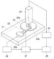
図1は第1の実施例のサーボトラックライタに適用されるHDDの斜視図を示し、HDD21上には磁気ディスク22が載置され、HDD21に付設して、磁気ヘッドアーム23の先端に磁気ディスク22に情報信号を書込む磁気記録ヘッドであるスライダを有する磁気ヘッド23aが設けられている。また、HDD21の上方には、磁気ディスク22のディスクハブ22aにレーザー光を照射して磁気ディスク22の回転速度を検出するLDV(Laser Doppler Velocimetor)光学ヘッド24が配置されている。
【0026】
LDV光学ヘッド24の出力は、信号処理ロジック回路25、回転位置検出回路26、セクタサーボパターン書込回路27、磁気ヘッド23aに順次に接続されており、トラック方向位置制御回路28の出力が、セクタサーボパターン書込回路27と、図示しないロータリポジショナに接続されている。
【0027】
このような構成により、磁気ヘッド23aのトラック方向は、図示しないロータリポジショナによって各トラックに対応して順次に位置制御され、LDV光学ヘッド24からのドップラ信号を処理する信号処理ロジック回路25から得られた磁気ディスク22の回転位置情報を基に、各トラック毎のサーボトラック信号を磁気ディスク22上に書き込んでゆく。
【0028】
図2(a) は回転位置に対応するLDV光学ヘッド24からのドップラ信号の信号振幅を示しており、この信号振幅はディスクハブ22aのレーザー光照射領域が同じであれば、回転位置に対して再現性がある。また、図2(b) はドップラ信号A、ドップラ信号Aを変換した波形整形信号B、回転位置原点信号Cを示している。ドップラ信号Aの周波数は、レーザー光照射位置のディスクハブ22a上の半径が常に同じであれば回転速度に比例する。
【0029】
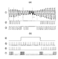
図3は第1の実施例のドップラ信号のドロップアウト部分の信号処理方法のグラフ図を示し、図3(a)において信号▲1▼はドップラ信号のエンベロープ(再現性)を示し、信号▲2▼はそのコンパレート信号である。このコンパレート信号▲2▼は閾値にヒステリシスを持たせることによって、ドップラ信号▲1▼のノイズ成分を取り除いており、ドロップアウト部ではコンパレート信号▲2▼がドップラ信号▲1▼に追従できなくなることを利用して、ドロップアウトを検出することができる。しかし、ドロップアウトの位置では信号振幅が小さく、微妙な振動によってもドップラ信号▲1▼の位相が変動したり振幅が変化したりするために、波形整形しても信号の再現性を確保することができないという問題がある。
【0030】
図3(b)はドロップアウト個所を特定するための信号処理のグラフ図を示す。先ず、ドロップアウト個所でない回転位置原点信号から最初のドロップアウト個所までの間で、PLL発振信号▲7▼の4分周信号▲5▼をドップラコンパレート信号に同期(位相ロック)させる。次に、図3(a)で示すようなドロップアウト不安定部分を網羅したドロップアウト特定信号▲3▼を、回転位置原点信号からのPLL発振信号▲7▼を計数することによりメモリする。
【0031】
ドロップアウト部では、PLL発振信号▲7▼に使用する図示しないVCOの電圧値を固定して、ドロップアウト直前の発振周波数にて発振させている。ドロップアウトの個所は距離換算で数10μm程度なので、ドロップアウト前後の回転速度はほぼ同一と見なせる。従って、ドロップアウト中にPLL発振信号▲7▼を計数することによって、ドロップアウト開始と回避のタイミングの再現性が良いドロップアウト特定信号▲3▼を生成することができる。
【0032】
ここで、図3(b)の信号▲4▼、▲5▼からドロップアウトの前後では、ドップラ信号の位相が一致しないことが多い。信号処理でこの位相ずれ分を出さないためにはドロップアウト回避を検出する信号としてドロップラコンパレート信号の複数逓倍(4逓倍)のPLL発振信号▲7▼を使用している。
【0033】
この方法により得られたPLLの基準信号は、信号▲2▼と信号▲3▼のORをとった信号▲4▼とする。その位相比較信号▲6▼はPLL発振信号▲7▼を基に信号▲4▼のドロップアウト回避後の立ち上がりとほぼ同期するようにして、ドロップアウト特定信号▲3▼の切換わりのPLL発振信号▲7▼のパルス数をメモリしてゆく。位相比較信号▲6▼はドロップアウトではない部分では、PLL発振信号▲7▼の4分周信号▲5▼をドップラコンパレート信号▲4▼に同期(位相ロック)させる。
【0034】
1回転中のドロップアウト個所は数10個所あるために、回転位置原点を基準としてドロップアウトでない領域とドロップアウト領域のそれぞれのPLL発振信号パルス数を、ドロップアウト不確定領域が存在しないように順次にメモリしながら、1回転分のドロップアウト個所を特定してゆき、最終的なドロップアウト特定信号▲3▼を確定する。
【0035】
図4はドロップアウトを順次にメモリしてゆく流れを示す。最初のドロップアウトD.O.1のPLL発振信号▲7▼のインデックスからのカウント値を先ず1回転目でメモリする。それにより、D.O.1の不安定をなくしたPLL発振信号を得ることができる。次のドロップアウトD.O.2のPLL発振信号▲7▼のインデックスからのカウント値は、2回転目でドロップアウト特定信号▲2▼により前述した処理を行い、インデックスからD.O.2までのPLL発振信号を安定させた上でメモリする。それにより、ドロップアウトD.O.1及びD.O.2の不安定をなくしたPLL発振信号▲7▼を得ることができる。
【0036】
同様に、D.O.3、D.O.4、…、D.O.nまで、3回転、4回転目、…、n回転で1回転に存在するD.O.個所n個分を順次にメモリしてゆき、1回転分の最終的なドロップアウト特定信号を確定する。
【0037】
このように、ドロップアウト個所を特定することができれば、ドロップアウト前後のランダムな信号の位相変化の不安定性をなくすことができる。回転位置原点からのドロップアウト特定信号▲9▼が確定できると、リアルタイムに検出されるドップラコンパレート信号▲2▼と信号▲3▼とのORにより、1周に渡り安定したPLLの基準信号▲4▼が生成され、かつPLL発振信号▲7▼と信号▲3▼により、1周に渡り安定したPLLの位相比較信号▲6▼が生成される。
【0038】
従って、PLLの基準信号▲4▼と位相比較信号▲6▼とによってPLL発振させることにより、1回転に渡り安定したPLL発振信号▲7▼が生成でき、エンコーダ信号と同等の安定した信号を得ることができる。
【0039】
また、1回転当たりのPLL発振パルスは回転位置原点をトリガとして計数することにより、特定することができる。それ以降はPLL発振パルス数を計数することによって回転位置原点を検出生成することができ、外部原点信号が不要となる。また、このときに同一回転の位置では常に同じ信号処理を行うことになるので、1回転で閉じた処理(クローズドループ)となってPLL発振の信号処理がより安定化して信号再現性が良好となる。
【0040】
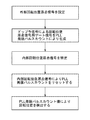
図5は信号処理ロジックR3のフローチャート図を示し、外部原点信号としては、サーボトラック信号を書き込む前に磁気ヘッド23aにより磁気ディスク22に原点信号を書き込んで、磁気ヘッド23aで原点信号を読み出している。この場合には、事前に磁気ディスク22を回転して1回転分のドロップアウト個所の特定信号を確定した後に、LDV光学ヘッド24の信号処理ロジックR3による原点信号を生成することができるので、サーボトラック信号を書き込む際に外部原点信号は不要となる。また、外部原点信号を設定する際に、ドロップアウト領域でない個所を選択することによって、信号処理ロジックR3による原点信号への安定した切換えを可能としている。この方法では、外部原点検出センサを別に設ける必要がないので、サーボトラックライタとして簡略化した構成を実現でき、実用的なシステムを提供することができる。
【0041】
図6は第2の実施例の信号処理方法のグラフ図を示し、ドップラ信号にドロップアウト状態が生じても高精度に回転位置検出を行うための信号処理方法である。
【0042】
図6(a)において、信号▲1▼はドップラ信号を示し、信号▲2▼はそのコンパレート信号である。このコンパレート信号▲2▼は、信号▲1▼のゼロ立ち下がりでHIに、ヒステリシスを持った閾値立ち上がりでLOになるよう設定され、ドップラ信号▲1▼のノイズ成分を取り除いている。信号▲3▼はドップラ信号▲1▼を3/16位相だけ先行させて、かつ閾値をコンパレート信号▲2▼と比べて小さくしたものである。
【0043】
図6(b) はドロップアウト個所を検出して信号処理を行うグラフ図を示し、ドロップアウト検出としては、信号▲2▼がHレベルになったままであるときをドロップアウト開始とし、信号▲2▼がLレベルになったときをドロップアウト終了とする。また、信号▲3▼の立ち上がり時に信号▲2▼がLレベルになっているときをドロップアウト開始とし、信号▲2▼がLレベルになっているときをドロップアウト終了とすると、常に信号▲2▼の立ち上がりの3/16位相を先行してドロップアウト検出を行うことができる。なお、信号▲4▼はドロップアウト検出信号である。
【0044】
先ず、ドロップアウト個所でない回転位置原点信号から最初のドロップアウト個所までの間で、PLL発振信号▲7▼の8分周信号▲5▼をドップラコンパレート信号に同期(位相ロック)させる。次に、ドロップアウト検出信号▲4▼がHレベルのドロップアウト部では、PLL発振信号▲7▼に使用する図示しないVCO(Voltage Control Oscillator)の電圧値を固定して、ドロップアウト直前の発振周波数で発振させる。具体的には、PLLの位相比較信号として、PLL発振信号▲7▼の8分周信号にドロップアウト検出信号▲4▼により、リセット掛けることにより生成した信号▲6▼を使用することにより、ドロップアウト時ではPLL基準信号とする信号▲2▼に信号立ち上がりがなく、また位相比較信号▲6▼にも信号立ち上がりがないために、PLL発振信号▲7▼は周波数調整が行われることなく、発振し続ける。
【0045】
ドロップアウトの個所は距離換算で数10μm程度なので、ドロップアウト前後の回転速度はほぼ同一と見倣せる。ここで、図6の信号▲2▼、▲5▼を比較すると、ドロップアウトの前後ではドップラ信号▲1▼の位相が一致していない。本実施例では、信号処理でこの位相ずれ分を事前に検出するために、ドロップアウト回避後にコンパレート信号▲2▼の立ち上がりに対して3/16位相を先行検出している。そして、検出信号▲4▼の立ち下がり後の8逓倍PLL発振信号▲7▼の3パルス目で、コンパレート信号▲2▼に同期させる信号▲6▼を生成して、次のドロップアウトまでPLL発振信号▲7▼を8分周して位相ロックしている。
【0046】
この方法により得られたPLLの位相比較信号▲6▼は、PLLの基準信号▲2▼に対してドロップアウト回避後の立ち上がりの量子化誤差(±1/16位相)分だけずれる可能性があるが、PLLの逓倍数を上げてゆけばその誤差は無視できる。
【0047】
また、先行検出せずにPLLの位相比較信号▲6▼を生成すると、量子化誤差はプラス1/8位相となり、量子化誤差累積は必ず増える方向となる。一方、本実施例のようにドロップアウトを先行して検出すると、量子化誤差をプラスとマイナスに割り振ることが可能となり、量子化誤差累積が一方向に加算することなく、累積の平均をゼロに持ってゆくことが可能となる。
【0048】
通常、1回転当たりのドロップアウトの個数は100個以下であるために、例えばPLLの逓倍数を128とすれば、1回転当たりのPLL発振パルス数の振れ(回転検出誤差)は、ドップラ信号▲1▼のパルス換算では最大でも±1/2パルス以上の誤差が生ずることはない。従って、PLL発振パルス数により同一回転位置でのドップラ信号▲1▼の立ち上がり場所のゲートを設定することができ、ゲートを通過したドップラ信号▲1▼の立ち上がりにより回転位置原点信号を生成することができる。この回転位置原点信号に一致するようにPLL発振信号▲7▼のパルス数をリセットすれば、PLL発振パルス数を読み取ることによって回転位置を検出することが可能となり、非接触でスケールを必要としない回転位置検出系を実現することができる。
【0049】
図7は信号処理ロジックR1のフローチャート図を示し、外部原点信号としては、サーボトラック信号を書き込む前に磁気ヘッド23aにより磁気ディスク22に原点信号を書き込んで、磁気ヘッド23aで原点信号を読み出している。この場合は、事前に磁気ディスク22を回転して1回転分のPLL発振信号パルス数を調べ、同一回転位置でのドップラ信号▲1▼の立ち上がり場所のゲートを設定する。これによって、LDV光学ヘッド24の信号処理ロジックR1による原点信号を生成することができるので、サーボトラック信号を書き込む際には、外部原点信号は不要となる。そして、このようにPLL発振パルス数を読み取ることにより回転位置を検出する。
【0050】
図8は第3の実施例の信号処理ロジックR2のフローチャート図を示し、外部原点信号としては第2の実施例と同様に、サーボトラック信号を書き込む前に磁気ヘッド23aにより磁気ディスク22に原点信号を書き込んで、磁気ヘッド23aで原点信号を読み出している。ここでは、事前に磁気ディスク22を回転して1回転分のPLL発振パルス数を調べると同時に、回転位置に対するドロップアウト個所をチェックし、PLL発振パルス数によってこのドロップアウト個所を概略メモリする。
【0051】
次に、外部原点信号とは別に、通常50個程度のセクタ毎の頭出し信号をドップラ信号▲1▼の立ち上がりに設定する。ここで、頭出し位置がメモリしたドロップアウト個所と一致した場合には、その直前のドロップアウトでない部分に頭出し信号を設定する。この頭出し信号に合わせて、PLL発振パルス数をリセットすると、リセットされたPLL発振信号▲7▼はドロップアウトによる信号処理の不安定性を含まずに、PLLの位相比較信号▲6▼の量子化誤差(±1/16位相)分のみとなる。この頭出し回転信号のパルス数とPLL発振パルス数の両方の計数値を読み取ることによって、回転位置を高精度に検出することができる。
【0052】
第2の実施例では、1回転分の量子化誤差の累積が回転位置検出誤差となり得るが、本実施例では量子化誤差の累積をセクタ数(50程度)分の1に分散するので、厳しい回転位置検出精度が必要な場合に特に有効となる。このような方法によって、ドロップアウトが存在するドップラ信号▲1▼においても、PLL発振信号▲7▼の周波数を極端に上げることなく、非常に再現性の良い回転位置検出を可能とする。なお、本実施例においてはセクタ頭出し信号を特定した時点で、外部原点信号は不要となる。
【0053】
図9は第4の実施例の要部の斜視図を示し、感光ドラム31の外周移動距離を検出するシステムに適用した例である。LDV光学ヘッド32の出力が、信号処理ロジック回路33、外周回転位置検出回路34、回転駆動制御回路35を介して感光ドラム31に接続されている。
【0054】
従来はロータリエンコーダによって感光ドラム31の外周移動量を検出する方法をとっているが、感光ドラム31の外周が回転軸に対し偏心していると、ロータリエンコーダからの移動検出量と実際の感光ドラム31の外周移動量とに、半径の誤差分に比例してずれが生ずるために、偏心のない機械的構成をとる必要がある。このために、本実施例ではLDV光学ヘッド32を使用してその信号を信号処理ロジック回路33を介して外周回転位置検出回路34で検出し、回転駆動制御回路35で感光ドラム31の回転を制御している。このように、外周の移動量をLDV光学ヘッド32からの光束で検出しているので、偏心を除去した回転位置情報を直ちに検出することができる。
【0055】
本実施例では、感光ドラム31の回転駆動を制御する方法を提示したが、例えば他の搬送系の駆動制御にフィ−ドバックしたり、感光プロセスの制御にフィードバックすることによって、最終的な転写性の高精度化を図ることもできる。ここでは図12の信号処理ロジックR3と同様に行うことができ、また外部信号としては、図示しない低分解能のロータリエンコーダを使用して、厳密な外周回転移動量の検出を行っている。
【0056】
次に第5の実施例について説明する。装置は図1の第1の実施例と同じ構成である。磁気ディスク22には、再現性を有する振れRROと再現性のない振れNRROが存在し、再現性のある振れRROは同一回転位置では同じようにずれる。従って、その振れRROが検出誤差として存在しても、各トラック上に同じ検出誤差として重畳されるために、サーボトラック信号を書き込むときの書込み誤差にはならない。一方、再現性のない振れNRROは検出誤差が各トラック毎にランダムに重畳してくるために、その振れNRROの検出誤差を極力抑えることが、サーボトラック信号の書き込みの高精度化に重要なポイントとなる。
【0057】
図10は磁気ディスク22、磁気ヘッド23aに対するLDV光学ヘッド24の検出方向の位置関係の平面図を示している。磁気ディスク22の中心に対する磁気ヘッド23aの方向をx軸として、振れNRROの振動幅Eに対するx軸方向の振動成分をEx、y軸方向の振動成分をEyとし、x軸に対するLDV検出方向Fの垂線の角度をα、LDV検出位置Dの磁気ディスク22の中心からの半径をrとすると、振れNRROがLDV検出方向Fに影響を与える検出誤差成分Sは、次式(6) となる。
S=−Ex・sin α+Ey・cos α …(6)
【0058】
また、振れNRがLDV検出の垂直方向に影響を与える半径誤差成分Vは、次式(7) となる。
V=Ex・cos α+Ey・sin α …(7)
【0059】
従って、磁気ディスク22の回転中心と磁気ヘッド23aとの距離をRとすると、磁気ヘッド23aでの振れNRROによるLDV検出誤差Eは、次式(8) に示すようになる。
E=(R/r)・S・(r+V)/r …(8)
【0060】
ここで、V≦E≪rであることから、次式(9) のように近似することができる。
E≒(R/r)・S
=(R/r)・(−Ex・sin α+Ey・cos α) …(9)
【0061】
この書込み位置ずれを書込み角度ずれωに換算すると、次式(10)のようになる。
ω=W/R=(1 /r)・(−Ex・sin α+Ey・cos α)−Ey/R…(10)
【0062】
一般に、振れNRROは方向に依存しない振動幅Eを持っており、その角度βはランダムな値0≦β<2πをとる。即ち、図11に示すようにハッチング部分の範囲内で、磁気ディスク22の中心がランダムにずれることを意味する。
【0063】
このとき、振れNRのx軸方向の振動成分Exとy軸方向の振動成分Eyを、E、βを用いて記述すると、次式(11)のようになる。
Ex=E・cos β、Ey=E・sin β …(11)
【0064】
式(11)を式(10)に代入すると、次式(12)となる。
ω=(E/r)・{−cos β・sin α+sin β・(cos α−r/R)} …(12)
【0065】
ここで、角度βは0≦β<2πの範囲内でランダムな値をとり得るので、LDV光学ヘッド24の設置角度αのときの振れNRROによる書込み角度ずれ|ω|のとり得る値は、次式(13)の角度βにおける最大値と等しくなる。
|ω|=|(E/r)・{−cos β・sin α+sin β・(cos α−r/R)}|…(13)
【0066】
式(13)の角度βにおける最大値をとる必要条件は、次式(14)のようにおくとdA/dβ=0である。
A=−cos β・sin α+sin β・(cos α−r/R) …(14)
【0067】
従って、dA/dβを求めると、次式(15)のように変形することができる。
dA/dβ=sin β・sin α+cos β・(cos α−r/R)
=cos(β−α)−(r/R)・cos β
=sin(β+π/2−α)−(r/R)・cos β
【0068】
ここで、次式(15)のようにおくと、式(16)のようになる。
c=sin(π/2−α)−r/R=cos α−r/R
d=cos(π/2−α)=sin α
sin Φ=c/(c2 +d2)1/2
cos Φ=d/(c2 +d2)1/2 …(15)
dA/dβ=(c2 +d2)1/2 ・sin(β+Φ) …(16)
dA/dβ=0とすると、式(16)よりβ=−Φとなる。
【0069】
従って、式(13)の角度βにおける最大値をとるための必要条件は、式(15)から次式(17)のようになる。
sin β=−c/(c2 +d2)1/2
cos β=d/(c2 +d2)1/2 …(17)
【0070】
式(17)を式(14)に代入すると、次式(18)のようになる。
A={−d・sin α−c・(cos α−r/R)}/(c2 +d2)1/2
=−{sin2α+(cosα−r/R)2}/{sin2α+(cosα−r/R)2}1/2
={sin2α+(cos α−r/R)2}1/2 …(18)
【0071】
これによって、振れNRROによる書込み角度ずれ|ω|の最大値ωmax は、次式(19)のようになる。
ωmax =|−(E/r)・{sin2α+(cosα−r/R)2}1/2|
=(E/r)・{1+(r/R)2−2・(r/R)・cos α}1/2 …(19)
【0072】
この式(19)からRが定数であれば、α=0rad のときにωmax が最小になることが分かる。
【0073】
ここで、6.3cm(2.5インチ)のHDD21として具体的な数値を考える。即ち、r=10mm、E=0.1μmとし、14mm≦R≦30mm(a=R/rとすると1.4≦a≦3)として、書込み角度ずれωmax を求めると図12〜図14に示すようになる。Rが範囲を持っているのは、磁気ヘッド23aのディスクトラック半径方向への移動を意味している。
【0074】
図12はLDV角度α、磁気ヘッド23aの位置aにおける書込み角度ずれωmax を三次元的に示したものであり、図13はa=1.4、2.2、3におけるLDV角度αと書込み角度ずれωmax との関係を示し、図14はα=0、π/6、π/3、π/2、2π/3、5π/6、πradにおける磁気ヘッド23aの位置aと書込み角度ずれωmax との関係を示している。
【0075】
これらの結果から、磁気ヘッド23aの位置aが1.4〜3の範囲で移動した場合においても、書込み角度ずれωmax が最小となるのはα=0rad であり、最大となるのはα=πradである。また、書込み角度ずれωmax の値は、LDV角度αの絶対値が同じであればαの符号に依存することはない。
【0076】
以上のことから、LDV光学ヘッド24の検出方向が、回転物体の中心と磁気ヘッド23aとを結ぶ直線に対して垂直近傍にあり、検出位置が回転物体中心に対して磁気ヘッド23a側にあるときに、回転物体の振れによる検出誤差に対して、最も影響を受けないLDV光学ヘッド24によるクロック信号を形成することができる。
【0077】
【発明の効果】
以上説明したように本発明に係る光学式回転位置情報検出装置は、回転位置情報検出手段が回転位置情報を特定する前に、回転物体を事前に回転することによって、回転位置情報を特定するための情報を検出することができるので、ドロップアウトが生ずる周波数信号においても、高精度で安定した回転位置を検出することが可能となる。
【図面の簡単な説明】
【図1】第1の実施例のハードディスクドライブの斜視図である。
【図2】回転位置に対するドップラ信号のグラフ図である。
【図3】第1の実施例の処理信号のグラフ図である。
【図4】ドロップアウトのメモリの流れを示す図である。
【図5】信号処理のフローチャート図である。
【図6】第2の実施例の処理信号のグラフ図である。
【図7】信号処理の処理信号のグラフ図である。
【図8】第3の実施例の信号処理のフローチャート図である。
【図9】第4の実施例の要部構成図である。
【図10】LDV光学ヘッドの検出方向の位置関係の説明図である。
【図11】再現性のない軸振れの説明図である。
【図12】LDV角度、磁気ヘッド位置における書き込み角度ずれのグラフ図である。
【図13】LDV角度の書き込み角度ずれのグラフ図である。
【図14】磁気ヘッドの位置と書き込み角度ずれのグラフ図である。
【図15】従来例のHDDの平面図である。
【図16】磁気ディスクの平面図である。
【図17】磁気ディスク上のサーボパターンの説明図である。
【図18】磁気式クロックヘッドを用いたHDDの斜視図である。
【図19】レーザードップラ速度計の構成図である。
【符号の説明】
21 ハードディスクドライブ
22 磁気ディスク
22a ディスクハブ
23a 磁気ヘッド
24、32 LDV光学ヘッド
25、33 信号処理ロジック回路
26、34 回転位置検出回路
27 セクタサーボパタ−ン書込回路
28 トラック方向位置制御回路
31 感光ドラム
35 回転駆動制御回路[0001]
BACKGROUND OF THE INVENTION
BACKGROUND OF THE
[0002]
[Prior art]
FIG. 15 is a plan view of a conventional recording / reproducing apparatus used in an information processing apparatus such as a computer. An HDD (Hard Disk Drive) 1 serving as a recording / reproducing apparatus has a
[0003]
FIG. 16 is a plan view of the
[0004]
With such a configuration, the
[0005]
When an information signal is written on the circular
[0006]
FIG. 18 shows a perspective view of the
[0007]
This
[0008]
In addition, since it is necessary to keep the gap between the
[0009]
As means for solving this problem, Japanese Patent Application Laid-Open No. 7-29229 discloses a laser Doppler method in which a light diffusion object is irradiated with laser light to detect rotational position information of the rotating object. According to this laser Doppler system, it is only necessary to irradiate the
[0010]
FIG. 19 shows a configuration diagram of a laser Doppler velocimeter, which uses a Doppler effect in which a moving object is irradiated with laser light, and the frequency of scattered light from the moving object shifts in proportion to the moving speed. Thus, the device measures the moving speed of the moving object. In this apparatus, a
[0011]
With such a configuration, the laser light emitted from the
[0012]
The frequency of the scattered light by the two light beams at this time undergoes a Doppler shift of + Δf and −Δf in proportion to the moving speed V, respectively. Here, if the wavelength of the laser beam is λ, Δf can be expressed by the following equation (1).
Δf = (Vsin θ) / λ (1)
[0013]
Scattered light that has undergone a Doppler shift of + Δf and −Δf interferes with each other and changes in brightness on the light receiving surface of the
F = 2Δf = (2Vsin θ) / λ (2)
[0014]
If the Doppler frequency F of the
[0015]
The velocity V when the object K to be measured is a rotating object is represented by the following equation (3), where r is the irradiation radius and W (rpm).
V = 2πrW / 60 (3)
[0016]
Therefore, the formula (2) finally becomes the following formula (4).
F = (πrWsin θ) / 15λ (4)
[0017]
When this equation (4) is converted into the number of pulses N per revolution, the following equation (5) is obtained.
N = (4πrsin θ) / λ (5)
[0018]
By detecting this pulse signal, the rotational position information can be detected.
[0019]
[Problems to be solved by the invention]
(1) However, it is known that the optical rotation position information detecting means for detecting the rotation position information by the above-described conventional Doppler signal has a dropout state where the signal is statistically missing. There is a problem that it is difficult to specify the rotational position with high accuracy.
[0020]
(2) Further, in the above-described conventional example, when the
[0021]
An object of the present invention is to solve the above-mentioned problem (1) and to provide an optical rotational position information detection device that detects the rotational position information in the circumferential direction on a continuously rotating rotating object with high accuracy. .
[0022]
Another object of the present invention is to provide an optical rotational position information detection device that eliminates the above-mentioned problem (2), minimizes the influence of the axial deflection of the rotating object, and enables highly accurate position detection. Is to provide.
[0023]
[Means for Solving the Problems]
In order to achieve the above object, an optical rotational position information detection apparatus according to the present invention is configured to emit a light beam from a light source means.RotateProject on a rotating object,In an optical rotational position information detection apparatus that has a photodetector that outputs a frequency signal corresponding to the rotational movement of scattered light from the rotating object, and detects rotational position information by performing signal processing on the frequency signal,The dropout part of the frequency signal detected by the photodetector is specified with reference to the rotation position origin signal of the rotating object from the outside, and a pulse signal having a frequency multiple of the frequency signal is oscillated, and the specified Dropout processing means for complementing the pulse signal in the state immediately before the dropout in the dropout section, and detecting the rotational position information by counting the complemented pulse signal based on the rotational position origin signal Detecting meansIt is characterized by that.
[0025]
DETAILED DESCRIPTION OF THE INVENTION
The present invention will be described in detail based on the embodiment shown in FIGS.
FIG. 1 is a perspective view of an HDD applied to the servo track writer of the first embodiment. A
[0026]
The output of the LDV
[0027]
With such a configuration, the track direction of the
[0028]
FIG. 2 (a) shows the signal amplitude of the Doppler signal from the LDV
[0029]
FIG. 3 is a graph of the signal processing method for the dropout portion of the Doppler signal according to the first embodiment. In FIG. 3A, signal (1) indicates the envelope (reproducibility) of the Doppler signal and signal (2). ▼ is the comparator signal. This comparator signal {circle around (2)} removes the noise component of the Doppler signal {circle around (1)} by giving hysteresis to the threshold, and the comparator signal {circle around (2)} cannot follow the Doppler signal {circle around (1)} in the dropout portion. Can be used to detect dropouts. However, the signal amplitude is small at the dropout position, and the phase of the Doppler signal (1) is changed or the amplitude is changed by subtle vibrations, so that signal reproducibility is ensured even if the waveform is shaped. There is a problem that can not be.
[0030]
FIG. 3B shows a graph of signal processing for specifying a dropout location. First, the divide-by-four signal {5} of the PLL oscillation signal {circle over (7)} is synchronized (phase-locked) with the Doppler comparator signal between the rotation position origin signal that is not the dropout location and the first dropout location. Next, the dropout specific signal {circle around (3)} covering the dropout unstable portion as shown in FIG. 3A is memorized by counting the PLL oscillation signal {circle around (7)} from the rotational position origin signal.
[0031]
In the dropout section, the voltage value of the VCO (not shown) used for the PLL oscillation signal (7) is fixed and oscillated at the oscillation frequency immediately before the dropout. Since the location of the dropout is about several tens of μm in terms of distance, the rotation speed before and after the dropout can be regarded as almost the same. Therefore, by counting the PLL oscillation signal (7) during the dropout, it is possible to generate the dropout specifying signal (3) with good reproducibility of the dropout start and avoidance timing.
[0032]
Here, the phase of the Doppler signal often does not match before and after the dropout from the signals (4) and (5) in FIG. In order to prevent this phase shift from occurring in signal processing, a PLL oscillation signal (7) of multiple multiplication (four multiplication) of the dropper comparator signal is used as a signal for detecting dropout avoidance.
[0033]
The reference signal of the PLL obtained by this method is a signal (4) obtained by ORing the signals (2) and (3). The phase comparison signal {circle around (6)} is substantially synchronized with the rise of the signal {circle over (4)} after avoiding the dropout based on the PLL oscillation signal {circle around (7)}, so that the dropout specific signal {circle around (3)} is switched. Memorize the number of pulses of (7). In the portion where the phase comparison signal {circle around (6)} is not a dropout, the divide-by-four signal {circle around (5)} of the PLL oscillation signal {circle around (7)} is synchronized (phase locked) with the Doppler comparator signal {circle around (4)}.
[0034]
Since there are several tens of dropout locations during one rotation, the number of PLL oscillation signal pulses in the non-dropout region and the dropout region are sequentially set so that there is no dropout indeterminate region with reference to the rotation position origin. While the memory is stored, the dropout part for one rotation is specified, and the final dropout specifying signal (3) is determined.
[0035]
FIG. 4 shows the flow of storing dropouts sequentially. First, the count value from the index of the PLL oscillation signal (7) of the first dropout D.O.1 is stored in the first rotation. As a result, a PLL oscillation signal that eliminates the instability of D.O.1 can be obtained. The count value from the index of the next dropout DO2 PLL oscillation signal (7) is processed by the dropout specific signal (2) at the second rotation to stabilize the PLL oscillation signal from the index to DO2. And then memorize it. As a result, the PLL oscillation signal {circle around (7)} that eliminates the instability of the dropouts D.O.1 and D.O.2 can be obtained.
[0036]
Similarly, until DO3, DO4, ..., DOn, the 3 rotations, the 4th rotation, ..., n rotations are stored in sequence for n DO locations that exist in one rotation, and the final one rotation Determine the specific dropout specific signal.
[0037]
Thus, if the dropout location can be specified, the instability of the phase change of the random signal before and after the dropout can be eliminated. When the dropout specific signal {circle around (9)} from the rotation position origin can be determined, the reference signal of the PLL stable over one round by the OR of the Doppler comparator signal {circle around (2)} and the signal {circle around (3)} detected in
[0038]
Therefore, by generating a PLL oscillation using the PLL reference signal (4) and the phase comparison signal (6), a stable PLL oscillation signal (7) can be generated over one rotation, and a stable signal equivalent to the encoder signal can be obtained. be able to.
[0039]
The PLL oscillation pulse per rotation isrotationIt can be specified by counting the position origin as a trigger. Thereafter, the rotational position origin can be detected and generated by counting the number of PLL oscillation pulses, and an external origin signal becomes unnecessary. At this time, since the same signal processing is always performed at the same rotation position, the processing is closed by one rotation (closed loop), the PLL oscillation signal processing is further stabilized, and the signal reproducibility is good. Become.
[0040]
FIG. 5 shows a flowchart of the signal processing logic R3. As the external origin signal, the origin signal is written on the
[0041]
FIG. 6 is a graph showing a signal processing method according to the second embodiment, which is a signal processing method for detecting a rotational position with high accuracy even when a dropout state occurs in a Doppler signal.
[0042]
In FIG. 6A, signal {circle around (1)} indicates a Doppler signal, and signal {circle around (2)} is its comparator signal. This comparator signal {circle around (2)} is set so as to become HI when the signal {circle around (1)} falls to zero, and to LO when the threshold rises with hysteresis, and removes the noise component of the Doppler signal {circle around (1)}. The signal {circle around (3)} is obtained by preceding the Doppler signal {circle around (1)} by 3/16 phase and making the threshold value smaller than that of the comparator signal {circle around (2)}.
[0043]
FIG. 6 (b) shows a graph for performing signal processing by detecting a dropout location. For dropout detection, when signal {circle around (2)} remains at the H level, dropout is started, and signal {circle around (2)}. The dropout ends when ▼ becomes L level. Further, when the signal {circle over (2)} is at the L level at the rising edge of the signal {circle around (3)}, the dropout starts, and when the signal {circle around (2)} is at the L level, the dropout ends, the signal {circle around (2)} Dropout detection can be performed in advance of the 3/16 phase of the rising edge of ▼. Signal (4) is a dropout detection signal.
[0044]
First, the divide-by-8 signal {5} of the PLL oscillation signal {circle over (7)} is synchronized (phase-locked) with the Doppler comparator signal between the rotation position origin signal that is not the dropout location and the first dropout location. Next, in the dropout portion where the dropout detection signal (4) is at the H level, the voltage value of a VCO (Voltage Control Oscillator) (not shown) used for the PLL oscillation signal (7) is fixed, and the oscillation frequency immediately before the dropout is set. Oscillate with Specifically, by using the signal {circle around (6)} generated by resetting the PLL oscillation signal {circle around (7)} divided by 8 with the dropout detection signal {circle around (4)} as the PLL phase comparison signal, When the signal is out, the signal (2) used as the PLL reference signal does not rise, and the phase comparison signal (6) also does not rise, so the PLL oscillation signal (7) oscillates without frequency adjustment. Keep doing.
[0045]
Since the location of the dropout is about several tens of μm in terms of distance, the rotation speed before and after the dropout can be assumed to be almost the same. Here, comparing the signals (2) and (5) in FIG. 6, the phase of the Doppler signal (1) does not match before and after the dropout. In this embodiment, in order to detect this phase shift in advance by signal processing, the 3/16 phase is detected in advance with respect to the rising edge of the comparator signal (2) after the dropout is avoided. Then, at the third pulse of the 8-fold PLL oscillation signal (7) after the fall of the detection signal (4), a signal (6) synchronized with the comparator signal (2) is generated, and the PLL is output until the next dropout. The oscillation signal {circle around (7)} is divided by 8 and phase locked.
[0046]
The PLL phase comparison signal {circle around (6)} obtained by this method may be shifted from the PLL reference signal {circle around (2)} by the rising quantization error (± 1/16 phase) after avoiding dropout. However, the error can be ignored if the PLL multiplication number is increased.
[0047]
If the PLL phase comparison signal {circle around (6)} is generated without detecting the preceding, the quantization error becomes a
[0048]
Usually, since the number of dropouts per rotation is 100 or less, for example, if the PLL multiplication number is 128, the fluctuation of the number of PLL oscillation pulses per rotation (rotation detection error) is the Doppler signal ▲ In the pulse conversion of 1 ▼, an error of ± 1/2 pulse or more does not occur at the maximum. Therefore, the gate of the rising position of the Doppler signal (1) at the same rotational position can be set by the number of PLL oscillation pulses, and the rotational position origin signal can be generated by the rising edge of the Doppler signal (1) passing through the gate. it can. If the number of pulses of the PLL oscillation signal (7) is reset so as to coincide with this rotation position origin signal, the rotation position can be detected by reading the number of PLL oscillation pulses, and no scale is required without contact. A rotational position detection system can be realized.
[0049]
FIG. 7 is a flowchart of the signal processing logic R1. As the external origin signal, the origin signal is written to the
[0050]
FIG. 8 shows a flowchart of the signal processing logic R2 of the third embodiment. As the external origin signal, the origin signal is applied to the
[0051]
Next, separately from the external origin signal, a cue signal for about 50 sectors is set at the rising edge of the Doppler signal (1). Here, if the cueing position matches the stored dropout location, a cueing signal is set in the portion not immediately before the dropout. When the number of PLL oscillation pulses is reset in accordance with this cue signal, the reset PLL oscillation signal (7) does not include instability of signal processing due to dropout, and the PLL phase comparison signal (6) is quantized. Only the error (± 1/16 phase) is included. By reading the count values of both the number of pulses of the cueing rotation signal and the number of PLL oscillation pulses, the rotational position can be detected with high accuracy.
[0052]
In the second embodiment, the accumulation of quantization error for one rotation can be a rotational position detection error. However, in this embodiment, the accumulation of quantization error is distributed to 1 / number of sectors (about 50), which is severe. This is particularly effective when rotational position detection accuracy is required. By such a method, even in the Doppler signal {circle around (1)} where the dropout exists, the rotational position can be detected with very good reproducibility without extremely increasing the frequency of the PLL oscillation signal {circle around (7)}. In the present embodiment, the external origin signal becomes unnecessary when the sector cue signal is specified.
[0053]
FIG. 9 shows a perspective view of the main part of the fourth embodiment, which is an example applied to a system for detecting the outer peripheral movement distance of the
[0054]
Conventionally, a method of detecting the outer peripheral movement amount of the
[0055]
In this embodiment, a method for controlling the rotational drive of the
[0056]
Next, a fifth embodiment will be described. The apparatus has the same configuration as that of the first embodiment shown in FIG. The
[0057]
FIG. 10 is a plan view showing the positional relationship in the detection direction of the LDV
S = −Ex · sin α + Ey · cos α (6)
[0058]
Further, the radial error component V that the shake NR affects the vertical direction of LDV detection is expressed by the following equation (7).
V = Ex · cos α + Ey · sin α (7)
[0059]
Accordingly, when the distance between the rotation center of the
E = (R / r) · S · (r + V) / r (8)
[0060]
Here, since V ≦ E << r, it can be approximated as the following equation (9).
E ≒ (R / r) ・ S
= (R / r) · (−Ex · sin α + Ey · cos α) (9)
[0061]
When this write position shift is converted into a write angle shift ω, the following equation (10) is obtained.
ω = W / R = (1 / r) · (−Ex · sin α + Ey · cos α) −Ey / R (10)
[0062]
In general, the vibration NRRO has a vibration width E that does not depend on the direction, and its angle β takes a
[0063]
At this time, when the vibration component Ex in the x-axis direction and the vibration component Ey in the y-axis direction of the shake NR are described using E and β, the following equation (11) is obtained.
Ex = E · cos β, Ey = E · sin β (11)
[0064]
Substituting equation (11) into equation (10) yields the following equation (12).
ω = (E / r) · {−cos β · sin α + sin β · (cos α−r / R)} (12)
[0065]
Here, since the angle β can take a random value within the range of 0 ≦ β <2π, the possible value of the writing angle deviation | ω | due to the shake NRRO when the installation angle α of the LDV
| Ω | = | (E / r) · {−cos β · sin α + sin β · (cos α−r / R)} |
[0066]
The necessary condition for taking the maximum value at the angle β in the equation (13) is dA / dβ = 0 as shown in the following equation (14).
A = −cos β · sin α + sin β · (cos α−r / R) (14)
[0067]
Therefore, when dA / dβ is obtained, it can be transformed as the following equation (15).
dA / dβ = sin β · sin α + cos β · (cos α−r / R)
= Cos (β-α)-(r / R) · cos β
= Sin (β + π / 2−α) − (r / R) · cos β
[0068]
Here, when the following equation (15) is set, the equation (16) is obtained.
c = sin (π / 2−α) −r / R = cos α−r / R
d = cos (π / 2−α) = sin α
sin Φ = c / (c2 + D2)1/2
cos Φ = d / (c2 + D2)1/2 … (15)
dA / dβ = (c2 + D2)1/2 ・ Sin (β + Φ) (16)
If dA / dβ = 0, then β = −Φ from equation (16).
[0069]
Therefore, the necessary condition for taking the maximum value at the angle β in the equation (13) is as follows from the equation (15) to the following equation (17).
sin β = −c / (c2 + D2)1/2
cos β = d / (c2 + D2)1/2 … (17)
[0070]
Substituting equation (17) into equation (14) yields equation (18) below.
A = {− d · sin α−c · (cos α−r / R)} / (c2 + D2)1/2
=-{Sin2α + (cos α−r / R)2} / {Sin2α + (cos α−r / R)2}1/2
= {Sin2α + (cos α−r / R)2}1/2 … (18)
[0071]
As a result, the maximum value ωmax of the write angle deviation | ω | due to the shake NRRO is expressed by the following equation (19).
ωmax = |-(E / r) · {sin2α + (cos α−r / R)2}1/2|
= (E / r) · {1+ (r / R)2-2 ・ (r / R) ・ cos α}1/2 … (19)
[0072]
From this equation (19), it can be seen that if R is a constant, ωmax is minimized when α = 0 rad.
[0073]
Here, specific numerical values are considered as the
[0074]
12 shows three-dimensionally the LDV angle α and the write angle deviation ωmax at the position a of the
[0075]
From these results, even when the position a of the
[0076]
From the above, when the detection direction of the LDV
[0077]
【The invention's effect】
As described above, the optical rotational position information detecting device according to the present invention specifies rotational position information by rotating a rotating object in advance before the rotational position information detecting means identifies rotational position information. Therefore, it is possible to detect a stable rotational position with high accuracy even in a frequency signal in which dropout occurs.
[Brief description of the drawings]
FIG. 1 is a perspective view of a hard disk drive according to a first embodiment.
FIG. 2 is a graph of a Doppler signal with respect to a rotational position.
FIG. 3 is a graph of processing signals of the first embodiment.
FIG. 4 is a diagram showing a memory flow of dropout.
FIG. 5 is a flowchart of signal processing.
FIG. 6 is a graph of processing signals of the second embodiment.
FIG. 7 is a graph of processing signals of signal processing.
FIG. 8 is a flowchart of signal processing according to the third embodiment.
FIG. 9 is a block diagram of the main part of a fourth embodiment.
FIG. 10 is an explanatory diagram of a positional relationship in the detection direction of the LDV optical head.
FIG. 11 is an explanatory diagram of shaft runout without reproducibility.
FIG. 12 is a graph of the write angle deviation at the LDV angle and the magnetic head position.
FIG. 13 is a graph of the write angle deviation of the LDV angle.
FIG. 14 is a graph of the position of the magnetic head and the write angle deviation.
FIG. 15 is a plan view of a conventional HDD.
FIG. 16 is a plan view of a magnetic disk.
FIG. 17 is an explanatory diagram of servo patterns on a magnetic disk.
FIG. 18 is a perspective view of an HDD using a magnetic clock head.
FIG. 19 is a configuration diagram of a laser Doppler velocimeter.
[Explanation of symbols]
21 Hard disk drive
22 Magnetic disk
22a disk hub
23a Magnetic head
24, 32 LDV optical head
25, 33 Signal processing logic circuit
26, 34 Rotation position detection circuit
27 Sector servo pattern writing circuit
28 Track direction position control circuit
31 Photosensitive drum
35 Rotation drive control circuit
Claims (7)
前記光検出器で検出した周波数信号のドロップアウト部を外部からの前記回転物体の回転位置原点信号を基準に特定し、前記周波数信号の複数倍の周波数のパルス信号を発振し、前記特定された前記ドロップアウト部に前記ドロップアウト直前の状態の前記パルス信号を補完するドロップアウト処理手段と、
前記回転位置原点信号を基準に前記補完されたパルス信号を計数することにより前記回転位置情報を検出する検出手段とを有することを特徴とする光学式回転位置情報検出装置。A light detector for projecting a light beam from a light source means on a rotating rotating object and outputting a frequency signal corresponding to the rotational movement of scattered light from the rotating object; In the optical rotational position information detecting device for detecting
The dropout part of the frequency signal detected by the photodetector is specified with reference to the rotation position origin signal of the rotating object from the outside, and a pulse signal having a frequency multiple of the frequency signal is oscillated, and the specified Dropout processing means for complementing the pulse signal in a state immediately before the dropout in the dropout unit;
An optical rotational position information detection apparatus comprising: a detecting means for detecting the rotational position information by counting the complemented pulse signals with reference to the rotational position origin signal.
Priority Applications (3)
| Application Number | Priority Date | Filing Date | Title |
|---|---|---|---|
| JP32030999A JP4298093B2 (en) | 1999-11-10 | 1999-11-10 | Optical rotational position information detector |
| US09/704,704 US6829118B1 (en) | 1999-11-10 | 2000-11-03 | Optical rotational position information detecting apparatus |
| US10/915,347 US7202979B2 (en) | 1999-11-10 | 2004-08-11 | Optical rotational position information detecting apparatus |
Applications Claiming Priority (1)
| Application Number | Priority Date | Filing Date | Title |
|---|---|---|---|
| JP32030999A JP4298093B2 (en) | 1999-11-10 | 1999-11-10 | Optical rotational position information detector |
Publications (3)
| Publication Number | Publication Date |
|---|---|
| JP2001141432A JP2001141432A (en) | 2001-05-25 |
| JP2001141432A5 JP2001141432A5 (en) | 2007-01-11 |
| JP4298093B2 true JP4298093B2 (en) | 2009-07-15 |
Family
ID=18120063
Family Applications (1)
| Application Number | Title | Priority Date | Filing Date |
|---|---|---|---|
| JP32030999A Expired - Fee Related JP4298093B2 (en) | 1999-11-10 | 1999-11-10 | Optical rotational position information detector |
Country Status (2)
| Country | Link |
|---|---|
| US (2) | US6829118B1 (en) |
| JP (1) | JP4298093B2 (en) |
Families Citing this family (11)
| Publication number | Priority date | Publication date | Assignee | Title |
|---|---|---|---|---|
| KR20060014155A (en) * | 2004-08-10 | 2006-02-15 | 삼성전자주식회사 | Disk recorder |
| JP2006351109A (en) * | 2005-06-16 | 2006-12-28 | Matsushita Electric Ind Co Ltd | Optical disk signal processing apparatus and optical disk reproducing apparatus |
| US7619844B1 (en) * | 2005-12-30 | 2009-11-17 | Western Digital Technologies, Inc. | Disk drive comprising a mechanical position sensor to prevent a runaway condition |
| US7495857B1 (en) | 2005-12-30 | 2009-02-24 | Western Digital Technologies, Inc. | Servo writing a disk drive by writing spiral tracks using a mechanical position sensor |
| US7480116B1 (en) | 2006-01-20 | 2009-01-20 | Western Digital Technologies, Inc. | Disk drive employing coarse position feedback from mechanical position sensor to improve format efficiency |
| US7924519B2 (en) * | 2008-09-29 | 2011-04-12 | Wd Media, Inc. | Eccentricity determination for a disk |
| JP2010175493A (en) * | 2009-02-02 | 2010-08-12 | Canon Inc | Laser doppler velocimeter |
| US8792193B2 (en) * | 2009-03-27 | 2014-07-29 | Agency For Science, Technology And Research | Magnetic media tester and a method of magnetic media testing |
| US9511976B2 (en) | 2011-03-31 | 2016-12-06 | Otis Elevator Company | Position feedback for elevator system |
| CN109917148A (en) * | 2019-04-08 | 2019-06-21 | 中国人民解放军战略支援部队航天工程大学 | Object rotation direction detection device based on superposition state vortex light |
| JP2021047944A (en) | 2019-09-18 | 2021-03-25 | 株式会社東芝 | Magnetic disk device |
Family Cites Families (20)
| Publication number | Priority date | Publication date | Assignee | Title |
|---|---|---|---|---|
| JP2899165B2 (en) | 1992-05-15 | 1999-06-02 | キヤノン株式会社 | Doppler speedometer and displacement information detector |
| JPH06197015A (en) * | 1992-12-24 | 1994-07-15 | Canon Inc | Frequency oscillator, period error detector, filter, signal deciding device and doppler velocity meter using them |
| US5502466A (en) | 1993-06-29 | 1996-03-26 | Canon Kabushiki Kaisha | Doppler velocimeter and position information detection apparatus for use with objects having variations in surface depth |
| JPH0729229A (en) | 1993-07-13 | 1995-01-31 | Pioneer Electron Corp | Magneto-optical disk, magneto-optical disk recording device and magneto-optical disk reproducing device |
| US6057976A (en) * | 1994-04-28 | 2000-05-02 | Canon Kabushiki Kaisha | Apparatus for detecting rotational displacement information of a rotating object |
| JP3491969B2 (en) | 1994-06-27 | 2004-02-03 | キヤノン株式会社 | Displacement information measuring device |
| JP3513247B2 (en) | 1994-07-11 | 2004-03-31 | キヤノン株式会社 | Frequency shifter and optical displacement measuring device using the same |
| JP3450446B2 (en) | 1994-08-03 | 2003-09-22 | キヤノン株式会社 | Optical displacement detector |
| US5815267A (en) | 1994-09-09 | 1998-09-29 | Canon Kabushiki Kaisha | Displacement information measuring apparatus in which a light-receiving condition on a photodetector is adjustable |
| US5796470A (en) | 1995-02-28 | 1998-08-18 | Canon Kabushiki Kaisha | Frequency shifter and optical displacement measuring apparatus using the frequency shifter |
| JP3492012B2 (en) | 1995-03-09 | 2004-02-03 | キヤノン株式会社 | Displacement information detection device |
| JPH08304430A (en) | 1995-05-12 | 1996-11-22 | Canon Inc | Frequency shifter and optical displacement measuring apparatus using it |
| US5796089A (en) * | 1995-09-21 | 1998-08-18 | Symbol Technologies, Inc. | Bar code scanner with simplified auto-focus capability |
| JPH09113523A (en) | 1995-10-23 | 1997-05-02 | Canon Inc | Doppler speedometer and driving system |
| JP3647135B2 (en) | 1996-04-15 | 2005-05-11 | キヤノン株式会社 | Optical displacement information measuring device |
| US6151185A (en) | 1996-09-05 | 2000-11-21 | Canon Kabushiki Kaisha | Position detecting apparatus, positioning apparatus, and information recording apparatus using the same |
| JPH10227858A (en) | 1997-02-13 | 1998-08-25 | Canon Inc | Displacement-information measuring apparatus |
| US6631047B2 (en) | 1997-09-22 | 2003-10-07 | Canon Kabushiki Kaisha | Interference device, position detecting device, positioning device and information recording apparatus using the same |
| JP2000321021A (en) * | 1999-05-10 | 2000-11-24 | Canon Inc | Interferometer, displacement measuring apparatus, and information recorder/reproducer employing it |
| JP4080281B2 (en) * | 2002-09-10 | 2008-04-23 | Ykk株式会社 | Button positioning device for button mounting machine |
-
1999
- 1999-11-10 JP JP32030999A patent/JP4298093B2/en not_active Expired - Fee Related
-
2000
- 2000-11-03 US US09/704,704 patent/US6829118B1/en not_active Expired - Fee Related
-
2004
- 2004-08-11 US US10/915,347 patent/US7202979B2/en not_active Expired - Fee Related
Also Published As
| Publication number | Publication date |
|---|---|
| US20050007919A1 (en) | 2005-01-13 |
| JP2001141432A (en) | 2001-05-25 |
| US6829118B1 (en) | 2004-12-07 |
| US7202979B2 (en) | 2007-04-10 |
Similar Documents
| Publication | Publication Date | Title |
|---|---|---|
| US5339204A (en) | System and method for servowriting a magnetic disk drive | |
| US5138594A (en) | Reducing amplitude variations of optical disk readback signals and increasing reliability of track-crossing counts | |
| JP4298093B2 (en) | Optical rotational position information detector | |
| JP3859282B2 (en) | Servo pattern writing method of magnetic disk device and magnetic disk device | |
| JPH09219026A (en) | Track count device for optical disk | |
| JPH09190651A (en) | Optical original disk exposing device and asynchronous deflection amount correcting device | |
| KR20060053171A (en) | A rotating recorder with dual encoder arrangement having eccentricity compensation | |
| US6785205B2 (en) | Apparatus for controlling eccentricity in photo-record player and control method thereof | |
| US6057976A (en) | Apparatus for detecting rotational displacement information of a rotating object | |
| JP2010072180A (en) | Correction system and electron beam drawing apparatus | |
| JP2010008833A (en) | Beam exposure apparatus and drawing control circuit of beam exposure apparatus | |
| US5724329A (en) | Apparatus for controlling rotational servo by using frequency pulse signal generator | |
| JP4580592B2 (en) | Optical disc master exposure system | |
| JP2008140419A (en) | Electron beam mastering device and rotational unevenness correction method | |
| JP2811816B2 (en) | Image rotator servo circuit | |
| JP2529351B2 (en) | Eccentricity correction device | |
| EP1040395B1 (en) | Control system, driving system and control method, apparatus including the driving system | |
| JPH11167730A (en) | Optical master plate recording device and method thereof | |
| US6188484B1 (en) | Method and apparatus for measuring angular displacement of an actuator arm relative to a reference position | |
| JP2616570B2 (en) | Servo track writing device | |
| JP2007095237A (en) | Encoder system and storage apparatus | |
| JPH0536097A (en) | Speed detection system for recording and reproducing head | |
| JP2579763B2 (en) | Tracking control device | |
| JPH10320943A (en) | Optical head servo writer | |
| JP2003317414A (en) | Device and method for writing servo information and magnetic disk drive |
Legal Events
| Date | Code | Title | Description |
|---|---|---|---|
| A521 | Written amendment |
Free format text: JAPANESE INTERMEDIATE CODE: A523 Effective date: 20061108 |
|
| A621 | Written request for application examination |
Free format text: JAPANESE INTERMEDIATE CODE: A621 Effective date: 20061108 |
|
| A977 | Report on retrieval |
Free format text: JAPANESE INTERMEDIATE CODE: A971007 Effective date: 20080627 |
|
| A131 | Notification of reasons for refusal |
Free format text: JAPANESE INTERMEDIATE CODE: A131 Effective date: 20081111 |
|
| A521 | Written amendment |
Free format text: JAPANESE INTERMEDIATE CODE: A523 Effective date: 20090108 |
|
| A131 | Notification of reasons for refusal |
Free format text: JAPANESE INTERMEDIATE CODE: A131 Effective date: 20090210 |
|
| A521 | Written amendment |
Free format text: JAPANESE INTERMEDIATE CODE: A523 Effective date: 20090303 |
|
| TRDD | Decision of grant or rejection written | ||
| A01 | Written decision to grant a patent or to grant a registration (utility model) |
Free format text: JAPANESE INTERMEDIATE CODE: A01 Effective date: 20090407 |
|
| A01 | Written decision to grant a patent or to grant a registration (utility model) |
Free format text: JAPANESE INTERMEDIATE CODE: A01 |
|
| A61 | First payment of annual fees (during grant procedure) |
Free format text: JAPANESE INTERMEDIATE CODE: A61 Effective date: 20090415 |
|
| R150 | Certificate of patent or registration of utility model |
Free format text: JAPANESE INTERMEDIATE CODE: R150 |
|
| FPAY | Renewal fee payment (event date is renewal date of database) |
Free format text: PAYMENT UNTIL: 20120424 Year of fee payment: 3 |
|
| LAPS | Cancellation because of no payment of annual fees |