JP4296604B2 - Encoded stream splicing apparatus and method, and encoded stream generation apparatus and method - Google Patents
Encoded stream splicing apparatus and method, and encoded stream generation apparatus and method Download PDFInfo
- Publication number
- JP4296604B2 JP4296604B2 JP52148099A JP52148099A JP4296604B2 JP 4296604 B2 JP4296604 B2 JP 4296604B2 JP 52148099 A JP52148099 A JP 52148099A JP 52148099 A JP52148099 A JP 52148099A JP 4296604 B2 JP4296604 B2 JP 4296604B2
- Authority
- JP
- Japan
- Prior art keywords
- stream
- encoding
- splicing
- encoded stream
- data
- Prior art date
- Legal status (The legal status is an assumption and is not a legal conclusion. Google has not performed a legal analysis and makes no representation as to the accuracy of the status listed.)
- Expired - Lifetime
Links
- 238000000034 method Methods 0.000 title claims description 103
- 238000010586 diagram Methods 0.000 description 45
- 230000005540 biological transmission Effects 0.000 description 41
- 230000006978 adaptation Effects 0.000 description 26
- 239000000463 material Substances 0.000 description 25
- 239000011159 matrix material Substances 0.000 description 16
- 239000013598 vector Substances 0.000 description 15
- 238000006243 chemical reaction Methods 0.000 description 14
- 238000013139 quantization Methods 0.000 description 10
- 230000000875 corresponding effect Effects 0.000 description 9
- 230000008520 organization Effects 0.000 description 9
- 230000001276 controlling effect Effects 0.000 description 4
- 238000005516 engineering process Methods 0.000 description 4
- 230000002457 bidirectional effect Effects 0.000 description 3
- 230000003139 buffering effect Effects 0.000 description 3
- 230000007812 deficiency Effects 0.000 description 3
- 230000001360 synchronised effect Effects 0.000 description 3
- 230000006835 compression Effects 0.000 description 2
- 238000007906 compression Methods 0.000 description 2
- 230000007547 defect Effects 0.000 description 2
- 230000003111 delayed effect Effects 0.000 description 2
- 230000002441 reversible effect Effects 0.000 description 2
- 102100037812 Medium-wave-sensitive opsin 1 Human genes 0.000 description 1
- 101000986989 Naja kaouthia Acidic phospholipase A2 CM-II Proteins 0.000 description 1
- 238000004891 communication Methods 0.000 description 1
- 239000002131 composite material Substances 0.000 description 1
- 230000002596 correlated effect Effects 0.000 description 1
- 230000006866 deterioration Effects 0.000 description 1
- 239000000284 extract Substances 0.000 description 1
- 230000003340 mental effect Effects 0.000 description 1
- 230000001343 mnemonic effect Effects 0.000 description 1
- 230000001737 promoting effect Effects 0.000 description 1
Images


Classifications
-
- H—ELECTRICITY
- H04—ELECTRIC COMMUNICATION TECHNIQUE
- H04N—PICTORIAL COMMUNICATION, e.g. TELEVISION
- H04N19/00—Methods or arrangements for coding, decoding, compressing or decompressing digital video signals
- H04N19/70—Methods or arrangements for coding, decoding, compressing or decompressing digital video signals characterised by syntax aspects related to video coding, e.g. related to compression standards
-
- H—ELECTRICITY
- H04—ELECTRIC COMMUNICATION TECHNIQUE
- H04N—PICTORIAL COMMUNICATION, e.g. TELEVISION
- H04N21/00—Selective content distribution, e.g. interactive television or video on demand [VOD]
- H04N21/20—Servers specifically adapted for the distribution of content, e.g. VOD servers; Operations thereof
- H04N21/23—Processing of content or additional data; Elementary server operations; Server middleware
- H04N21/234—Processing of video elementary streams, e.g. splicing of video streams or manipulating encoded video stream scene graphs
- H04N21/23406—Processing of video elementary streams, e.g. splicing of video streams or manipulating encoded video stream scene graphs involving management of server-side video buffer
-
- H—ELECTRICITY
- H04—ELECTRIC COMMUNICATION TECHNIQUE
- H04N—PICTORIAL COMMUNICATION, e.g. TELEVISION
- H04N21/00—Selective content distribution, e.g. interactive television or video on demand [VOD]
- H04N21/20—Servers specifically adapted for the distribution of content, e.g. VOD servers; Operations thereof
- H04N21/23—Processing of content or additional data; Elementary server operations; Server middleware
- H04N21/234—Processing of video elementary streams, e.g. splicing of video streams or manipulating encoded video stream scene graphs
- H04N21/23424—Processing of video elementary streams, e.g. splicing of video streams or manipulating encoded video stream scene graphs involving splicing one content stream with another content stream, e.g. for inserting or substituting an advertisement
-
- H—ELECTRICITY
- H04—ELECTRIC COMMUNICATION TECHNIQUE
- H04N—PICTORIAL COMMUNICATION, e.g. TELEVISION
- H04N21/00—Selective content distribution, e.g. interactive television or video on demand [VOD]
- H04N21/40—Client devices specifically adapted for the reception of or interaction with content, e.g. set-top-box [STB]; Operations thereof
- H04N21/43—Processing of content or additional data, e.g. demultiplexing additional data from a digital video stream; Elementary client operations, e.g. monitoring of home network or synchronising decoder's clock; Client middleware
- H04N21/44—Processing of video elementary streams, e.g. splicing a video clip retrieved from local storage with an incoming video stream or rendering scenes according to encoded video stream scene graphs
- H04N21/44004—Processing of video elementary streams, e.g. splicing a video clip retrieved from local storage with an incoming video stream or rendering scenes according to encoded video stream scene graphs involving video buffer management, e.g. video decoder buffer or video display buffer
-
- H—ELECTRICITY
- H04—ELECTRIC COMMUNICATION TECHNIQUE
- H04N—PICTORIAL COMMUNICATION, e.g. TELEVISION
- H04N21/00—Selective content distribution, e.g. interactive television or video on demand [VOD]
- H04N21/40—Client devices specifically adapted for the reception of or interaction with content, e.g. set-top-box [STB]; Operations thereof
- H04N21/43—Processing of content or additional data, e.g. demultiplexing additional data from a digital video stream; Elementary client operations, e.g. monitoring of home network or synchronising decoder's clock; Client middleware
- H04N21/44—Processing of video elementary streams, e.g. splicing a video clip retrieved from local storage with an incoming video stream or rendering scenes according to encoded video stream scene graphs
- H04N21/44016—Processing of video elementary streams, e.g. splicing a video clip retrieved from local storage with an incoming video stream or rendering scenes according to encoded video stream scene graphs involving splicing one content stream with another content stream, e.g. for substituting a video clip
-
- H—ELECTRICITY
- H04—ELECTRIC COMMUNICATION TECHNIQUE
- H04N—PICTORIAL COMMUNICATION, e.g. TELEVISION
- H04N21/00—Selective content distribution, e.g. interactive television or video on demand [VOD]
- H04N21/80—Generation or processing of content or additional data by content creator independently of the distribution process; Content per se
- H04N21/81—Monomedia components thereof
- H04N21/812—Monomedia components thereof involving advertisement data
Landscapes
- Engineering & Computer Science (AREA)
- Multimedia (AREA)
- Signal Processing (AREA)
- Business, Economics & Management (AREA)
- Marketing (AREA)
- Compression Or Coding Systems Of Tv Signals (AREA)
- Television Signal Processing For Recording (AREA)
- Time-Division Multiplex Systems (AREA)
- Studio Circuits (AREA)
Description
技術分野
本発明は、デジタル放送システムにおいて使用される符号化ストリームスプライシング装置及び符号化ストリームスプライシング方法、並びに、符号化ストリーム生成装置及び符号化ストリーム生成方法であって、特には、2つの符号化ストリームをストリームレベルでスプライシングすることによってシームレスなスプライスドストリームを生成する符号化ストリームスプライシング装置及び符号化ストリームスプライシング方法、並びに、符号化ストリーム生成装置及び符号化ストリーム生成方法に関する。
背景技術
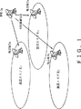
図1は、現在のテレビジョン放送システムを説明するための図である。現在のテレビジョン放送システムにおいて、各家庭にテレビ番組を配信するための放送局は、全国規模のテレビ番組を制作する本局(キーステーション又はメインステーション)SKと、地方特有のテレビ番組を作成する本局系列の複数の地方局(支局)SA、SB、及びSCとから構成されている。本局SKは、全国共通のテレビ番組を作成し、その作成したテレビ番組を地方局に伝送するための放送局であって、地方局は、本局から局間伝送によって送られて来たオリジナルテレビ番組、及びそのオリジナルテレビ番組一部を地方特有向けに編集したテレビ番組の両方の番組を地方の家庭に配信するための放送局である。例えば、図1に示されるように、地方局SAは、放送エリアEA内の家庭に伝送するテレビ番組を作成する局であって、地方局SBは、放送エリアEB内の家庭に伝送するテレビ番組を作成する局であって、地方局SCは、放送エリアEC内の家庭に伝送するテレビ番組を作成する局である。尚、この各地方局において行われる編集処理とは、例えば、本局から送られてきたニュース番組に、地方独自の天気予報のプログラムを挿入したり、映画やドラマ等の番組に、地方向けのコマーシャルを挿入したりする処理のことである。
図2は、各地方局における編集処理を説明するための図であって、図2Aは、本局において制作されたオリジナルテレビ番組PGOLDを示し、図2Bは、地方局において制作された地方向けの差し替えテレビ番組PGNEWであって、図2Cは、地方局において編集されたテレビ番組PGEDITを示している。図2に示された編集処理の例は、本局から伝送されてきたオリジナルテレビ番組のうち、コマーシャルCM1、プログラム3、及びコマーシャルCM3を、地方局において地方向けに制作されたコマーシャルCM1’、プログラム3’、及びコマーシャルCM3’に置き換える編集処理の例である。この地方局における編集処理の結果、図2Cに示されるように、本局において生成されたテレビ番組(プログラム1、プログラム2、CM2、及びプログラム4)と地方局において生成されたテレビ番組(コマーシャルCM1’、プログラム3’、及びCM3’)とが混在する地方向けのテレビ番組が生成される。
近年、現在のテレビジョン放送システムはアナログのベースバンドのテレビジョン信号を各家庭に配信するアナログ放送であるため、これらのアナログ方法システムを、デジタル技術を使用した次世代の放送システムに置換えようという試みがなされている。このデジタル放送システムは、MPEG2(Moving Picture Experts Group Phase2)等の圧縮符号化技術を用いてビデオデータやオーディオデータを圧縮符号化し、その符号化されたストリームを地上波や衛星波を利用して各家庭や他局に伝送するシステムである。特に、このデジタル放送システムとして提案されている放送技術の中で、ヨーロッパにおいて次世代の放送方式として提案されているDVB(Digital Video Broadcasting)規格が最も有力であって、このDVB規格がデファクトスタンダートとなりつつある。
次に、図3を参照してMPEG規格を用いて、ビデオデータとオーディオデータを含んだプログラムを送信側システムから受信側システムに伝送する一般的なデジタル伝送システムに関して説明する。
一般的なデジタル伝送システムにおいて、伝送側システム10は、MPEGビデオエンコーダ11と、MPEGオーディオエンコーダ12と、マルチプレクサ13とを備え、受信側システム20は、デマルチプレクサ21と、MPEGビデオデコーダ22と、MPEGオーディオデコーダ23とを備えている。
MPEGビデオエンコーダ11は、ベースバンドのソースビデオデータVをMPEG規格に基いて符号化し、その符号化したストリームをビデオエレメンタリストリームESとして出力する。MPEGオーディオエンコーダ12は、ベースバンドのソースオーディオデータAをMPEG規格に基いて符号化し、その符号化したストリームをオーディオエレメンタリストリームESとして出力する。マルチプレクサ13は、MPEGビデオエンコーダ11とMPEGオーディオエンコーダ12から、それぞれビデオエレメンタリーストリームとオーディオエレメンタリストリームを受取り、それらのストリームをトランスポートストリームパケットの形態に変換し、ビデオエレメンタリストリームを含んだトランスポートストリームパケットとオーディオエレメンタリストリームを含んだトランスポートストリームパケットを生成する。さらに、マルチプレクサ13は、ビデオエレメンタリストリームを含んだトランスポートストリームパケットとオーディオエレメンタリストリームを含んだトランスポートストリームパケットとが混在するように、それぞれのトランスポートストリームパケットを多重化し、受信システム20に伝送されるトランスポートストリームを生成する。
デマルチプレクサ21は、伝送路を介して伝送されたトランスポートストリームを受取り、ビデオエレメンタリストリームを含んだトランスポートストリームとオーデイオエレメンタリストリームを含んだトランスポートストリームパケットとに分離する。さらに、デマルチプレクサ21は、ビデオエレメンタリストリームを含んだトランスポートストリームパケットからビデオエレメンタリーストリームを生成するとともに、オーディオエレメンタリストリームを含んだトランスポートストリームパケットからオーディオエレメンタリーストリームを生成する。MPEGビデオデコーダ22は、デマルチプレクサ21からビデオエレメンタリーストリームを受取り、このビデオエレメンタリストリームをMPEG規格に基いてデコードし、ベースバンドのビデオデータVを生成する。MPEGオーディオデコーダ22は、デマルチプレクサ21からオーディオエレメンタリーストリームを受取り、このオーディオエレメンタリストリームをMPEG規格に基いてデコードし、ベースバンドのオーディオデータAを生成する。
さて、従来のアナログ放送システムをこのようなデジタル伝送システムの技術を使用してデジタル放送システムに置き換えようとした場合、本局から地方局に向けて伝送されるテレビ番組のビデオデータは、MPEG2規格に基いて圧縮符号化された符号化ストリームとなる。従って、地方局において本局から伝送されたオリジナル符号化ストリームの一部を、地方局において制作された符号化ストリームに置換えるための編集処理を行なうためには、この編集処理の前に、一端、符号化ストリームをデコードして、ベースバンドのビデオデータに戻さなければいけない。なぜなら、MPEG規格に準じた符号化ストリームに含まれる各ピクチャの予測方向は、前後のピクチャの予測方向と相互に関連しているので、ストリーム上の任意の位置において符号化ストリームを接続することができないからである。もし強引に2つの符号化ストリームをつなげたとすると、符号化ストリームのつなぎめが不連続になってしない、正確にデコードできなくなってしまうことが発生する。
従って、図2において説明したような編集処理を実現するためには、本局から供給されたオリジナルの符号化ストリームと、地方向けに制作された符号化ストリームの両方を一端デコードし、それぞれをベースバンドのビデオ信号に戻すデコード処理と、2つのベースバンドのビデオデータを編集してオンエア用の編集されたビデオデータを生成する編集処理と、編集されたビデオデータを再び符号化して、符号化ビデオストリームを生成するという符号化処理とを行なわなくてはいけない。しかしながら、MPEG規格に基く符号化/復号化処理は100%可逆の符号化/復号化処理ではないので、復号化処理及び符号化処理を繰り返すたびに画質が劣化してしまうという問題があった。
そこで、近年では、供給された符号化ストリームを復号化処理せずに、符号化ストリームの状態のまま編集することを可能にする技術が要求されるようになってきた。尚、このように符号化されたビットストリームレベルで、異なる2つの符号化ビットストリームを連結し、連結されたビットストリームを生成することを「スプライシング」と呼んでいいる。つまり、スプライシングとは、符号化ストリームの状態のままで複数のストリームを編集及び接続することを意味する。
しかしながら、このスプライシング処理を実現するためには以下のような2つの問題点がある。
まず、第1の問題点について説明する。
上述したMPEGビデオエンコーダ11及びMPEGビデオデコーダ22において使用されているMPEG規格では、符号化方式として双方向予測符号化方式が採用されている。この双方向予測符号化方式では、フレーム内符号化、フレーム間順方向予測符号化および双方向予測符号化の3つのタイプの符号化が行われ、各符号化タイプによる画像は、それぞれIピクチャ(intra coded picture)、Pピクチャ(predictive coded picture)およびBピクチャ(bidirectionally predictive coded picture)と呼ばれる。また、I,P,Bの各ピクチャを適切に組み合わせて、ランダムアクセスの単位となるGOP(Group of Picture)が構成される。一般的には、各ピクチャの発生符号量は、Iピクチャが最も多く、次にPピクチャが多く、Bピクチャが最も少ない。
MPEG規格のようにピクチャ毎にビット発生量が異なる符号化方法では、得られる符号化ビットストリーム(以下、単にストリームとも言う。)をビデオデコーダにおいて正確に復号化して画像を得るためには、ビデオデコーダ22における入力バッファ内のデータ占有量を、ビデオエンコーダ11で把握していなければならない。そこで、MPEG規格では、ビデオデコーダ22における入力バッファに対応するバッファとして‘VBV(Video Buffering Verifier)バッファ’という仮想バッファを想定し、ビデオエンコーダ11では、VBVバッファを破綻、つまりアンダフローやオーバフローさせないように、符号化処理を行なうように定義されている。例えば、このVBVバッファの容量は、伝送される信号の規格に応じて決められており、メインプロファイル・メインレベル(MP@ML)のスタンダードビデオ信号の場合であれば、1.75Mビットの容量を有している。ビデオエンコーダ11は、このVBVバッファをオーバフローやアンダフローさせないように、各ピクチャのビット発生量をコントロールする。
次に、図4を参照して、VBVバッファについて説明する。
図4Aは、本局において制作されたプログラム1とコマーシャルCM1とを含んだオリジナルテレビ番組を、ビデオエンコーダで符号化したオリジナルストリームSTOLDと、そのオリジナルストリームSTOLDに対応するVBVバッファのデータ占有量の軌跡を示す図である。図4Bは、地方向けに制作されたコマーシャルであって、オリジナルテレビ番組のコマーシャルCM1の部分に差し替えられるコマーシャルCM1’を、地方局のビデオエンコーダで符号化した差し替えストリームSTNEW、その差し替えストリームSTNEWのVBVバッファのデータ占有量の軌跡を示す図である。尚、以下の説明において、本局から支局に伝送されたオリジナルテレビ番組を符号化したストリームの一部が支局において作成された新たなストリームによって置き換えられるので、このオリジナルテビ番組を符号化したオリジナルストリームを、古いストリームであることを示す‘STOLD’と表現し、オリジナルストリームSTOLDの一部に新たに差し替えられる差し替えストリームを‘STNEW’と表現する。図4Cは、スプライスポイントSPにおいてオリジナルストリームSTOLDに対して差し替えストリームSTNEWをスプライシングすることによって得られたスプライスドストリームSTSPL(spliced stream)と、そのスプライスドストリームSTSPLのVBVバッファのデータ占有量の軌跡を示す図である。
尚、図4において、VBVバッファのデータ占有量の軌跡において、右上がり部分(傾き部分)は伝送ビットレートを表し、垂直に落ちている部分は各ピクチャの再生のためにビデオデコーダがデコーダバッファから引き出すビット量を表している。ビデオデコーダがこのデコーダバッファからビットを引き出すタイミングは、デコーデイングタイムスタンプ(DTS)と呼ばれる情報によって指定される。なお、図4においてI,P,Bは、それぞれIピクチャ,Pピクチャ,Bピクチャを表している。
オリジナル符号化ストリームSTOLDは本局のビデオエンコーダ符号化されたストリームであって、差し替えストリームSTNEWは地方局のビデオエンコーダで符号化されたストリームであるので、オリジナル符号化ストリームSTOLDと差し替えストリームSTNEWとは、それぞれのビデオエンコーダで全く関係無く符号化されたストリームである。よって、地方局のビデオエンコーダは、本局のビデオエンコーダのVBVバッファのデータ占有量の軌跡を全く知らずに、独自に差し替えストリームSTNEWを生成するための符号化処理を行っているので、スプライスポイントSPにおけるオリジナルストリームSTOLDのVBVバッファのデータ占有量VBVOLDと、スプライスポイントSPにおける差し替えストリームSTNEWのVBVバッファのデータ占有量VBVNEWとは異なってしまう。
つまり、スプライスドストリームSTSPLのスプライスポイントSPの前後において、VBVバッファのデータ占有量の軌跡が不連続にならないようにするためには、スプライスドストリームSTSPLにおける差し替えストリームSTNEWのVBVバッファのデータ占有量の初期レベルは、VBVバッファのデータ占有量VBVOLDにしなければいけない。その結果、図4に示したように、オリジナルストリームSTOLDのVBVバッファのデータ占有量VBVOLDよりも、差し替えストリームSTNEWのVBVバッファのデータ占有量VBVNEWの値が小さい場合には、スプライスドストリームSTSPLにおける差し替えストリームSTNEWの部分で、VBVバッファがオーバーフローしてしまう。また、逆に、オリジナルストリームSTOLDのVBVバッファのデータ占有量VBVOLDよりも、差し替えストリームSTNEWのVBVバッファのデータ占有量VBVNEWの値が大きい場合には、スプライスストリームSTSPLにおける差し替えストリームSTNEWの部分で、VBVバッファがアンダーフローしてしまう。
次に、第2の問題について説明する。
MPEG規格に基いて符号化されたストリームのヘッダには、符号化情報を示すさまざまなデータエレメントやフラグが記述されており、これらのデータエレメントやフラグを使用して符号化ストリームを復号化するようになされている。
図2に示されたオリジナルテレビ番組の本編を構成するプログラム1、プログラム2、プログラム3及びプログラム4は、ビデオカメラ等によって撮影された29.97Hz(約30Hz)のフレームレートを有するNTSC方式のテレビジョン信号とは限らず、24Hz(毎秒24コマ)のフレームレートを有する映画素材からテレビジョン信号に変換された信号であることもある。一般的に、このように24Hzの映画素材を29.97Hzのテレビジョン信号に変換する処理を、オリジナル素材における2個のフィールドを、所定のシーケンスで3個のフィールドに変換する処理を含むことから、‘2:3プルダウン処理’と呼んでいる。
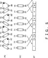
図5は、この2:3プルダウン処理を説明するための図である。図5において、T1からT8は24Hzのフレーム周波数を有する映画素材のトップフィールドを示し、B1からB9は24Hzのフレーム周波数を有する映画素材のボトムフィールドを示している。さらに、図5において示された楕円及び三角形は、トップフィールドとボトムフィールドから構成されるフレームの構造を示している。
具体的には、この2:3プルダウン処理において、24Hzのフレーム周波数を有する映画素材(8個のトップフィールドT1〜T8、及び8個のボトムフィールドB1〜B8)に、ボトムフィールドB2を繰り返すことによって生成されたリピートフィールドB2’、トップフィールドT4を繰り返すことによって生成されたリピートフィールドT4’、ボトムフィールドB6を繰り返すことによって生成されたリピートフィールドB6’、及びトップフィールドT8を繰り返すことによって生成されたリピートフィールドT8’の4つのリピートフィールドを挿入する処理が行われる。その結果、この2:3プルダウン処理によって、24Hzのフレーム周波数を有する映画素材から29.97Hzのフレーム周波数を有するテレビジョン信号が生成される。
MPEGエンコーダにおいて、2:3プルダウン処理されたテレビジョン信号は、ビデオエンコーダにおいてそのまま符号化処理されるのではなく、2:3プルダウン処理されたテレビジョン信号からリピートフィールドを除去してから、符号化処が行われる。図5に示した例では、2:3プルダウンされたテレビジョン信号から、リピートフィールドB2’、T4’、B6’及びT8’が除去される。このように符号化処理前にリピートフィールドを除去する理由は、このリピートフィールドは、2:3プルダウン処理時に挿入された冗長なフィールドであって、圧縮符号化効率を向上させるために削除したとしても何ら画質劣化が発生しないからである。
また、MPEG規格においては、符号化ストリームをデコードする際に、フレームを構成する2つのフィールドのいずれかのフィールドを繰り返すことによって、リピートフィールドを生成するか否かを示す‘repeat_first_field’というフラグを記述することを定義付けている。具体的には、MPEGデコーダは、符号化ストリームをデコードする際に、符号化ストリーム中のフラグ「repeat_first_field」が「1」の場合にはリピートフィールドを生成し、符号化ストリーム中のフラグ「repeat_first_field」が「0」の場合にはリピートフィールドを生成しないという処理を行なう。
図5に示した例の場合には、トップフィールドT1とボトムフィールドB1とから構成されるフレームを符号化したストリームの「repeat_first_field」は「0」であって、トップフィールドT2とボトムフィールドB2とから構成されるフレームを符号化したストリームの「repeat_first_field」は「1」であって、トップフィールドT3とボトムフィールドB3とから構成されるフレームを符号化したストリームの「repeat_first_field」は「0」であって、トップフィールドT4とボトムフィールドB4とから構成されるフレームを符号化したストリームの「repeat_first_field」は「1」であるので、トップフィールドT2とボトムフィールドB2とから構成されるフレームの符号化ストリームをデコードする時には、リピートフィールドB2’を生成し、トップフィールドT4とボトムフィールドB4とから構成されるフレームの符号化ストリームをデコードする時には、リピートフィールドB4’を生成する処理を行なう。
さらに、MPEG規格においては、フレームを構成する2つのフィールドのうち、最初のフィールドがトップフィールドかボトムフィールドかを示す‘top_field_first’というフラグを、符号化ストリーム中に記述することを定義している。具体的には、「top_field_first」が「1」である場合には、トップフィールドがボトムフィールドよりも時間的に早いフレーム構造であることを示し、「top_field_first」が「0」の場合には、トップフィールドがボトムフィールドよりも時間的に早いフレーム構造であることを示す。
図5に示した例では、トップフィールドT1とボトムフィールドB1から構成されるフレームの符号化ストリームの「top_field_first」は「0」であって、トップフィールドT2とボトムフィールドB2から構成されるフレームの符号化ストリームの「top_field_first」は「1」であって、トップフィールドT3とボトムフィールドB3から構成されるフレームの符号化ストリームの「top_field_first」は「0」であって、トップフィールドT4とボトムフィールドB4から構成されるフレームの符号化ストリームの「top_field_first」は「1」である。
次に、図6を参照して、符号化ストリームをスプライシング処理したときの「top_field_first」及び「repeat_first_field」等のMPEG規格において定義されているフラグに関して発生する問題点について説明する。
図6Aは、本局において制作されたオリジナルテレビ番組を符号化したオリジナルストリームSTOLDのフレーム構造を示している図であって、図6Bは、地方局において制作された地方向けのコマーシャルC1’を符号化した差し替えストリームSTNEWのフレーム構造を示している図であって、図6Cは、スプライシング処理されたスプライスドストリームSTSPLのフレーム構造を示している図である。
オリジナルストリームSTOLDにおけるプログラム1及びプログラム2は、共に2:3プルダウン処理された符号化ストリームであって、本編のコマーシャルCM1の各フレームは、「top_field_first」が「0」となっているフレーム構造の符号化ストリームである。また、図6Bに示された、地方コマーシャルCM1’は、オリジナルテレビ番組のコマーシャルCM1の部分に差し替えられる符号化ストリームであって、「top_field_first」が「1」となっているフレーム構造の符号化ストリームである。図6Cに示されたスプライスドストリームSTSPLは、プログラム1で示されるオリジナルストリームSTOLDの後に、差し替えストリームSTNEWをスプライスし、さらに、差し替えストリームSTNEWの後に、プログラム2で示されるオリジナルストリームSTOLDをスプライスすることによって生成されたストリームである。つまり、スプライスドストリームSTSPLは、オリジナルストリームSTOLDの本編コマーシャルCM1の替わりに地方コマーシャルCM1’を挿入したストリームである。
図6に示した本局において制作されたコマーシャルCM1の各フレームは、top_field_firstが「0」のフレーム構造の符号化ストリームであって、地方局において制作されたコマーシャルCM1’は、top_field_firstが「1」のフレーム構造の符号化ストリームであることを示している。
図6A及び図6Bに示したように、コマーシャルCM1のフレーム構造と、コマーシャルCM1に対して差し替えられる差し替えコマーシャルCM1’のフレーム構造とが異なる場合に、オリジナルストリームSPOLDのスプライスポイントSP1で、プログラム1のストリームの後にコマーシャルCM1’のストリームをスプライスすると、スプライスドストリームSTSPLにおいてフィールドのギャップが生じてしまう。フィールドのギャップとは、図6Cに示されたように、スプライスポイントSP1におけるボトムフィールドB6が、スプライスドストリームSTSPLから脱落し、トップフィールドとボトムフィールドの繰り返しパターンが不連続になっていることを意味している。
このようにフィールドのギャップが生じてフィールドパターンが不連続になっている符号化ストリームは、MPEG規格違反の符号化ストリームであって、通常のMPEGデコーダでは正常に復号化できない。
また、図6A及び図6Bに示したように、オリジナルストリームSPOLDのスプライスポイントSP2で、コマーシャルCM1’のストリームの後にプログラム2のストリームをスプライスすると、スプライスドストリームSTSPLにおいてフィールドの重複が生じてします。このフィールドの重複とは、図6Cに示されたように、スプライスポイントSP2におけるボトムフィールドb12及びボトムフィールドB12が同じ表示時間に存在することになってしまうことを意味している。
このようにフィールドの重複が生じてフィールドパターンが不連続になっている符号化ストリームは、MPEG規格違反の符号化ストリームであって、通常のMPEGデコーダでは正常に復号化できない。
つまり、単純にスプラシング処理を行なうと、フィールドパターン/フレームパターンが不連続になってしまい、MPEG規格に準じたスプライスドストリームを生成することができなかった。
発明の開示
本発明の目的は、スプライシングされたストリームのVBVバッファのデータ占有量の軌跡が連続であって、且つ、VBVバッファば破綻しないシームレスなスプライシング処理を実現するための符号化ストリームスプライシング装置を提供することにある。さらには、スプライシングポイント前後における、符号化ストリームのストリーム構造が不連続にならないシームレスなスプライシング処理を実現するための符号化ストリームスプライシング装置を提供することにある。
本発明の編集装置及びスプライシング装置によれば、第1のソース符号化ストリームに対して2のソース符号化ストリームをスプライシングするスプライシングポイントにおける符号化パラメータを取得する符号化パラメータ取得手段と、画像データを符号化処理して符号化ストリームを生成する符号化手段と、上記符号化パラメータ取得手段により取得された符号化パラメータを利用して上記第2のソース符号化ストリームに対応する画像データを符号化処理するように上記符号化手段を制御する制御手段と、上記第1のソース符号化ストリームと上記符号化手段により符号化された上記第2の符号化ストリームとをスプライシングするスプライシング手段とを備えることによって、スプライシングされたストリームのVBVバッファのデータ占有量の軌跡が連続であって、且つ、VBVバッファは破綻しないシームレスなスプライシング処理を実現することができる。また、本発明によれば、スプライシングポイント前後における、符号化ストリームのストリーム構造が不連続にならない整合性の取れたシームレスなストリームを生成することのできるスプライシング処理を実現できる。
また、本発明の編集方法及びスプライシング方法によれば、第1のソース符号化ストリームに対して第2のソース符号化ストリームをスプライシングするスプライシングポイントにおける符号化パラメータを取得する符号化パラメータ取得ステップと、画像データを符号化処理して符号化ストリームを生成する符号化ステップと、上記符号化パラメータ取得ステップにより取得された符号化パラメータを利用して上記第2のソース符号化ストリームに対応する画像データを符号化処理するように、上記符号化ステップの符号化処理を制御する制御ステップと、上記第1のソース符号化ストリームと上記符号化ステップにより符号化された上記第2の符号化ストリームとをスプライシングするスプライシングステップとを含むことによって、スプライシングされたストリームのVBVバッファのデータ占有量の軌跡が連続であって、且つ、VBVバッファは破綻しないシームレスなスプライシング処理を実現することができる。
また、本発明によれば、スプライシングポイント前後における、符号化ストリームのストリーム構造が不連続にならない整合性の取れたシームレスなストリームを生成することのできるスプライシング処理を実現できる。
【図面の簡単な説明】
図1は、一般的なテレビジョン放送システムを説明するための図である。
図2は、地方局におけるテレビ番組の編集処理を説明するための図である。
図3は、MPEG規格を用いた一般的なデジタル伝送システムを説明するための図である。
図4A〜図4Cは、VBVバッファの制御について説明するための図である。
図5は、2:3プルダウン処理を説明するための図である。
図6A〜図6Cは、符号化ストリームをスプライシング処理したときに発生する問題点を説明するための図である。
図7は、本発明の実施の形態に係る符号化ストリームスプライシング装置を含むデジタル放送システムを全体構成を示すブロック図である。
図8は、本局30のMPEGエンコーダブロック35及び地方局40のエンコーダブロックの構成を詳細に説明するためのブロック図である。
図9A〜図9Dは、ストリーム変換回路においてエレメンタリーストリームからトランスポートストリームを生成するときの処理を説明するための図である。
図10は、MPEGのビデオエレメンタリーストリームのシーケンスのシンタックスを説明するための図である。
図11は、シーケンスヘッダ(sequence_header)のシンタックスを説明するための図である。
図12は、シーケンスエクステンション(sequence_extension)のシンタックスを説明するための図である。
図13は、エクステンションアンドユーザデータ(extension_and_user_data)のシンタックスを説明するための図である。
図14は、グルーブオブピクチャヘッダ(group_of_picture_header)のシンタックスを説明するための図である。
図15は、ピクチャヘッダ(picture_headr)のシンタックスを説明するための図である。
図16は、ピクチャコーディングエクステンション(picture_coding_extension)のシンタックスを説明するための図である。
図17は、ピクチャヘッダ(picture_date)のシンタックスを説明するための図である。
図18は、トランスポートストリームパケットのシンタックスを説明するための図である。
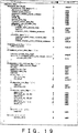
図19は、アダプテーションフィールド(adaptation_field)のシンタックスを説明するための図である。
図20は、地方局の簡単な構成及びストリームスプライサの構成を説明するためのブロック図である。
図21A内示図21Cは、ストリームスプライサのVBVバッファに関する処理を説明するための図である。
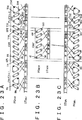
図22A〜図22Bは、ストリームスプライサのtop_field_first及びrepeat_first_fieldに関する第1の処理例を説明するための図である。
図23A〜図23Cは、ストリームスプライサのtop_field_first及びrepeat_first_fieldに関する第2の処理例を説明するための図である。
発明を実施するための最良の形態
図7は、本発明の実施の形態に係る符号化ストリームスプライシング装置を含むデジタル放送システムを構成を示す図である。
図7に示されているように、一般的には、デジタル放送システムは主局(Key station)30と、この主局系列の地方局40とから構成されている。
主局30は、系列の地方局に対して共通のテレビプログラムを制作及び伝送するための放送局であって、放送システムコトローラ31と、素材サーバ32と、CMサーバ33と、マトリックススイッチャブロック34と、MPEGエンコーダブロック35と、マルチプレクサ36と、変調回路37とから構成されている。
放送システムコトローラ31は、素材サーバ32、CMサーバ33、マトリックススイッチャブロック34、MPEGエンコーダブロック35、マルチプレクサ36、及び変調回路37等の放送局に設けられている全ての装置及び回路を統合的に管理及びコントロールするシステムである。この放送システムコトローラ31は、番組供給会社から供給された番組素材及びプロモーション素材や自局で作成した番組素材やCM素材などのあらゆる素材の放映時間を管理するための番組編成表が登録されており、放送番組編成システム1は、この番組編成表に従って、上述した各装置及び回路を制御する。この番組編成表は、例えば、1時間単位又は1日単位の放送番組スケジュールが記録されているイベント情報ファイル、及び15秒単位の放送番組のタイムスケジュールが記録されている運行情報ファイル等から構成されている。
素材サーバ32は、テレビ番組の本編として放送される映画番組、スポーツ番組、娯楽番組、ニュース番組等のビデオデータ及びオーディオデータを格納すると共に、放送システムコントローラ31によって指定されたプログラムを、番組編成表のタイムスケジュールに従ったタイミングで出力するためのサーバである。また、この映画番組とは、先に説明したように、24Hzのフレーム周波数を有するフィルム素材から2:3プルダウン処理することによって30Hzのフレーム周波数を有するテレビジョン信号に変換されたビデオデータである。この素材サーバ32から本編のプログラムとして出力されたビデオデータ及びオーディオデータはマトリックススイッチャブロック34に供給される。例えば、図2に示した例では、プログラム1、プログラム2、プログラム3及びプログラム4等がこの素材サーバ32に記録されている。尚、この素材サーバ32に記憶されているビデオデータ及びオーディオデータは、圧縮符号化されていないベースバンドのビデオデータ及びオーディオデータである。
CMサーバ33は、素材サーバ32から再生された本編のプログラム間に挿入されるコマーシャルを格納すると共に、放送システムコントローラ31によって指定されたコマーシャルを、番組編成表のタイムスケジュールに従ったタイミングで出力するためのサーバである。このCMサーバ33からコマーシャルとして出力されたビデオデータ及びオーディオデータはマトリックススイッチャ34に供給される。例えば、図2に示した例では、コマーシャルCM1、コマーシャルCM2、及びコマーシャルCM3等が、このCMサーバ33に記録されている。尚、このCMサーバ33に記憶されているビデオデータ及びオーディオデータは、圧縮符号化されていないベースバンドのビデオデータ及びオーディオデータである。
マトリックススイッチャブロック35は、スポーツ中継やニュース番組等のライブプログラム、素材サーバ32から出力された本編プログラム、及びCMサーバ33から出力されたコマーシャルプログラムをそれぞれルーティングするマトリックス回路を有している。さらに、マトリックススイッチャブロック35は、放送システムコントローラによって決定された番組編成表のタイムスケジュールに従ったタイミングで、素材サーバ32から供給された本編プログラムとCMサーバ33から供給されたコマーシャルプログラムを接続してスイッチングするスイッチング回路を有している。このスイッチング回路によって、本編プログラムとCMプログラムをスイッチングすることによって、例えば図2に示した伝送プログラムPGOLDを生成することができる。
MPEGエンコーダブロック35は、マトリックススイッチャブロックから出力されたベースバンドのビデオデータ及びオーディオデータをMPEG2規格に基いて符号化するためのブロックであって、複数のビデオエンコーダ及びオーディオエンコーダを有している。
マルチプレクサ36は、MPEGエンコーダブロック35から出力された9チャンネルのトランスポートストリームを多重化して、1つの多重化トランスポートストリームを生成する。従って、出力される多重化トランスポートストリーム中には、1から9チャンネルまでの符号化ビデオエレメンタリーストリームを含んだトランスポートストリームパケットと1チャンネルから9チャンネルまでの符号化オーディオエレメンタリーストリームを含んだトランスポートストリームパケットとが混在しているストリームである。
変調回路37は、トランスポートストリームをQPSK変調して、その変調されたデータを伝送路を介して、地方局40及び家庭61に伝送する。
次に、地方局40の全体構成に関して、図7を参照して説明する。
地方局40は、本局から送られてきた共通のテレビプログラムを地方向けに編集し、地方向けに編集されたテレビ番組みを各家庭に放映するめの放送局であって、放送システムコートローラ41と、復調回路42と、デマルチプレクサ43と、ストリーム変換回路44と、素材サーバ46と、CMサーバ47と、エンコーダブロック48と、ストリームサーバ49と、ストリームスプライサ50と、ストリームプロセッサ51と、マルチプレクサ52と、変調回路53とを備えている。
放送システムコトローラ41は、本局30の放送システムコントローラ31と同じように、復調回路42、デマルチプレクサ43、ストリーム変換回路44、素材サーバ46、CMサーバ47、エンコーダブロック48、ストリームサーバ49、ストリームスプライサ50、ストリームプロセッサ51、マルチプレクサ52、変調回路53等の地方局に設けられている全ての装置及び回路を統合的に管理及びコントロールするシステムである。この放送システムコントローラ41は、本局30における放送システムコントローラ31と同様に、本局30から供給された伝送プログラムに対して、自局で作成した番組やCMなどを挿入した編集テレビ番組の放映時間を管理するための番組編成表が登録されており、この番組編成表に従って、上述した各装置及び回路を制御する。
復調回路42は、伝送路を介して本局30から伝送された伝送ピログラムをQPSK復調することによって、トランスポートストリームを生成する。
デマルチプレクサ43は、復調回路42から出力されたトランスポートスリームをデマルチプレックスして9チャンネルのトランスポートストリームを生成し、それぞれのチャンネルのトランスポートストリームをストリーム変換回路44に出力する。つまり、このデマルチプレクサ43は、本局30のマルチプレクサ36とは逆の処理を行なう。
ストリーム変換回路44は、デマルチプレクサ43から供給されたトランスポートストリームをエレメンタリーストリームの形態に変換するための回路である。
素材サーバ46は、地方向けのテレビ番組として放送される娯楽番組、ニュース番組等のビデオデータ及びオーディオデータを格納しているサーバである。CMサーバ47は、本局30から供給された本編プログラム間に挿入される地方向けコマーシャルのビデオデータ及びオーディオデータを格納するためのサーバである。この素材サーバ46及びCMサーバ47に記憶されているビデオデータ及びオーディオデータは、圧縮符号化されていないベースバンドのビデオデータ及びオーディオデータである。
エンコーダブロック48は、素材サーバ46及びCMサーバ47から供給された複数チャンネルのビデオデータ及び複数チャンエルのオーディオデータを符号化するためのブロックであって、複数チャンネルに対応した複数のビデオエンコーダ及び複数のオーディオエンコーダを備えている。このエンコーダブロック48と本局30のMPEGエンコーダブロック35との違いは、本局30のMPEGエンコーダブロック35はトランスポートストリームを出力するのに対して、この地方局40のエンコーダブロック48は、エレメンタリーストリーム出力する点で異なっているが、このエンコーダブロック48の実質的な機能及び処理は本局30のMPEGエンコーダブロック35と全く同じである。エンコーダブロック48から出力された複数チャンネルのエレメンタリーストリームのうち3チャンネル分のエレメンタリーストリームが、ストリームサーバ49に供給され、残りのチャンネルのエレメンタリーストリームは、ストリームスプライサ50に供給される。
ストリームサーバ49は、エンコーダブロックから供給された3チャンネル分のエレメンタリーストリームを受取り、ストリームの状態でランダムアクセス可能な記録媒体にストリームの状態で記録すると共に、放送システムコントローラ41からの制御にしたがって、そのエレメンタリーストリームをランダムアセクス可能な記録媒体から再生する。
ストリームスプライサ50は、エンコーダブロック48及びストリームサーバ49から供給された複数のエレメンタリースをルーティングして所定の出力ラインに出力すると共に、本局30から供給されたエレメンタリーストリームと、地方局40において生成されたエレメンタリーストリームとをストリームレベルでスプライシングするためのブロックである。このストリームスプライサ50における処理は、詳しくは後述する。
ストリーム変換回路51は、ストリームスプライサ50からスプライスドストリームとして出力されたエレメンタリーストリームを受けとり、このエレメンタリーストリームをトランスポートストリームに変換する回路である。
マルチプレクサ52は、本局30のマルチプレクサ36と同じように、ストリーム変換回路から出力された9チャンネルのトランスポートストリームを多重化して、1つの多重化トランスポートストリームを生成する。
変調回路53は、トランスポートストリームをQPSK変調して、その変調されたデータを伝送路を介して、各家庭62に配信する。
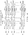
図8は、本局30のMPEGエンコーダブロック35及び地方局40のエンコーダブロック48の構成を詳細に説明するためのブロック図である。本局30のMPEGエンコーダブロック35と地方局40のエンコーダブロック48とは実質的に同じ構成であるので、本局30のMPEGエンコーダブロック35を例にあげて、その構成及び昨日を説明する。
MPEGエンコーダブロック35は、このMPEGエンコーダブロック35の全ての回路を集中的に制御するためのエンコーダコントローラ350と、供給された複数チャンネルのビデオデータをエンコードするための複数のMPEGビデオエンコーダ351−1V〜351−9Vと、ビデオデータにそれぞれ対応する複数のオーディオデータをMPEG2規格に基いて符号化するためのMPEGオーディオエンコーダ351−1A〜351−9Aとを有している。
さらに、MPEGエンコーダブロック35は、各ビデオエンコーダ351−1V〜351−9Vからそれぞれ出力された符号化エレメンタリーストリーム(ES)をトランスポートストリームに変換するストリーム変換回路352−1V〜352−9Vと、各オーディオエンコーダ351−1A〜351−9Aからそれぞれ出力された符号化エレメンタリーストリーム(ES)をトランスポートストリームに変換するストリーム変換回路352−1A〜352−9Aと、第1チャンネル(1ch)のビデオエレメンタリーストリームを含んだトランスポートストリームと、第1チャンネル(1ch)のオーディオエレメンタリーストリームを含んだトランスポートストリームとをトランスポートストリームパケット単位で多重化するマルチプレクサ353−1と、第2チャンネル(2ch)のビデオエレメンタリーストリームを含んだトランスポートストリームと、第2チャンネル(2ch)のオーディオエレメンタリーストリームを含んだトランスポートストリームとをトランスポートストリームパケット単位で多重化するマルチプレクサ353−2と、....、第9チャンネル(9ch)のビデオエレメンタリーストリームを含んだトランスポートストリームと、第9チャンネル(9ch)のオーディオエレメンタリーストリームを含んだトランスポートストリームとをトランスポートストリームパケット単位で多重化するマルチプレクサ353−9とを備えている。
図8に示したMPEGエンコーダブロック35は、9チャンネルの伝送プログラムをエンコードする構成となっているが、9チャンネルに限らず何チャンネルであっても良いことは言うまでもない。
図8に示したMPEGエンコーダブロック35は、各チャンネルの伝送プログラムの伝送レートを、符号化するビデオデータの絵柄に応じてダイナミックに変化させる統計多重という制御を行なう。この統計多重という手法は、あるチャンネルの伝送プログラムのピクチャの絵柄が比較的簡単であって、このピクチャを符号化するためにそれほど多くのビットを必要としない場合であって、一方、その他のプログラムのピクチャの絵柄が比較的難しく、このピクチャを符号化するために多くのビットを必要とすような場合には、あるチェンネルのピクチャを符号化するためのビットを、その他のチャンネルのピクチャを符号化するビットに割当てることによって、伝送路の伝送レートを効率良くしようすることができる方法である。以下に、このようにダイナミックに各ビデオエンコーダの符号化レートを変化させる方法について簡単に説明する。
各ビデオエンコーダ351−1V〜351−9Vは、まず、符号化処理の前に行われる動き補償の結果得られた動き補償残差やイントラAC等の統計量から、符号化対象となっているピクチャを符号化するためにどの程度のビット量が必要かを示すディフィカルティデータ(Difficulty Data)D1〜D9を生成する。このディフィカルティデータとは、符号化難易度を示す情報であって、ディフィカルティが大きいということは符号化対象となっているピクチャの絵柄が複雑であることを表わし、ディフィカルティが小さいということは符号化対象となっているピクチャの絵柄が簡単であることを表わしている。このデイフィカルティデータは、ビデオエンコーダにおける符号化処理時に使用される、イントラACや動き補償残差(ME残差)等の統計量に基いて、概算することができる。
エンコーダコントローラ350は、各ビデオエンコーダ351−1V〜351−9Vからそれぞれ出力されたディフィカルティデータD1〜D9を受取り、それらのディフィカルティデータD1〜D9に基いて、各ビデオエンコーダ351−1V〜351−9Vに対するターゲットビットレートR1〜R9をそれぞれ演算する。具体的には、以下の式(1)に示すように、エンコーダコントローラ350は、伝送路のトータル伝送レートTotal_Rateを、ディフィカルティデータD1〜D9を用いて比例配分することによって、ターゲットビットレートR1〜R9を求めることができる。
Ri=(Di/ΣDk)×Total_Rate … (1)
式(1)において、「Ri」は「i」チャンネルの伝送プログラムのターゲットビットレート、「Di」は「i」チャンネルの伝送プログラムのピクチャを符号化するためのディフィカルティデータ、「Σ」はk=1〜9チャンネルのディフィカルティデータの総和を意味する。
エンコーダコントローラ350は、式(1)に基いて演算したターゲットビットレートR1〜R9を、それぞれ対応するビデオエンコーダ351−1V〜351−9Vに供給する。このターゲットビットレートR1〜R9を演算する単位は、各ピクチャ毎であっても良いし、またGOP単位であっても良い。
ビデオエンコーダ351−1V〜351−9Vは、エンコーダコントローラ350から供給されたターゲットビットレートR1〜R9をそれぞれ受取り、このターゲットビットレートR1〜R9に対応するように符号化処理を行なう。このように符号化するピクチャの符号化難易度を示すディフィカルティデータに基いて、各ビデオエンコーダから出力される符号化ストリームのビットレートをダイナミックに変更することによって、符号化すべきピクチャの符号化難易度に対して最適な量のビットを割り当てることができ、さらに、各ビデオエンコーダからそれぞれ出力されるビットレートの総量が、伝送路のトータル伝送レートTotal_Rateをオーバーフローすることがない。
ストリーム変換回路352−1V〜352−9V及び、ストリーム変換回路352−1A〜352−9Aは、共に、エレメンタリーストリームをトランスポートストリームに変換するための回路である。
図9を参照して、ビデオエンコーダ351−1Vにおいて、供給されたソースビデオデータを符号化してビデオエレメンタリーストリームを生成し、そのビデオエレメンタリーストリームを、ストリーム変換回路352−1Vにおいてトランスポートストリームに変換する例を挙げて、ビデオエレメンタリーストリームからトランスポートストリームを生成する過程について説明する。
図9Aは、ビデオエンコーダ351−1Vに供給されるソースビデオデータを示し、図9Bは、ビデオエンコーダ351−1Vから出力されたビデオエレメンタリーストリーム(ES)を示し、図9Cは、パケッライズドエレメンタリーストリーム(PES)、図9Dは、トランスポートストリーム(TS)を示している。
図9Bに示したストリームV1、V2、V3及びV4のように、MPEG2規格において符号化されたエレメンタリーストリームのデータ量は、ビデオフレームのピクチャタイプ(Iピクチャ、Pピクチャ又はBピクチャ)及び動き補償の有無に応じて異なってくる。図9Cに示したパケッタイズドエレメンタリーストリーム(PES)は、その複数のエレメンタリーストリームをパケット化し、その先頭にPESヘッダを付加することによって生成される。例えば、このPESヘッダには、PESパケットの開始を示す24〔bit〕のパケット開始コードと、PESパケットの実データ部分に収容されるストリームデータの種別(例えばビデオや音声等の種別)を示す8〔bit〕のストリームIDと、以降に続くデータの長さを示す16〔bit〕のパケット長と、値「10」を示すコードデータと、各種フラグ情報が格納されるフラグ制御部と、コンディショナル・コーデイング部のデータの長さを示す8〔bit〕のPESヘッダ長と、PTS(Presentation Time Stamp)と呼ばれる再生出力の時間情報やDTS(Decoding Time Stamp)と呼ばれる復号時の時刻管理情報、或いはデータ量調整のためのスタッフィングバイト等が格納される可変長のコンディショナル・コーデイング部とによって構成される。
トランスポートストリーム(TS)は、4バイトのTSヘッダと184バイトの実データが記録されるペイロード部とから成るトランスポートストリームパケットのデータ列である。このトランスポートストリームパケット(TSパケット)を生成するためには、まず、PESパケットのデータストリームを184バイト毎に分解し、その184バイトの実データをTSパケットのペイロード部に挿入し、その184バイトのペイロードのデータに4バイトのTSヘッダを付加することによってトランスポートストリームパケットが生成される。
次に、図10から図17を参照してエレメンタリーストリームのシンタックス及び構造について説明すると共に、図18から図19を参照してトランスポートストリームのシンタックス及び構造について詳しく説明する。
図10は、MPEGのビデオエレメンタリーストリームのシンタックスを表わした図である。ビデオエンコーダブロック35内の各ビデオエンコーダ351−1V〜351−9Vは、この図10に示されたシンタックスに従った符号化エレメンタリーストリームを生成する。以下に説明するシンタックスにおいて、関数や条件文は細活字で表わされ、データエレメントは、太活字で表されている。データ項目は、その名称、ビット長及びそのタイプ・伝送順序を示すニーモニック(Mnemonic)で記述されている。
まず、この図10に示されているシンタックスにおいて使用されている関数について説明する。実際には、この図10に示されているシンタックスは、ビデオデコーダ側において伝送された符号化ストリームから所定の意味のあるデータを抽出するために使用されるシンタックスである。ビデオエンコーダ側において使用されるシンタックスは、図10に示されたシンタックスからif分やwhile文等の条件文を省略したシンタックスである。
video_sequesce()において最初に記述されているnext_start_code()関数は、ビットストリーム中に記述されているスタートコードを探すための関数である。この図6に示されたシンタックスに従って生成された符号化ストリームには、まず最初に、sequence_header()関数とsequence_extension()関数によって定義されたデータエレメントが記述されている。このsequence_header()関数は、MPEGビットストリームのシーケンスレイヤのヘッダデータを定義するための関数であって、seqnence_extension()関数は、MPEGビットストリームのシーケンスレイヤの拡張データを定義するための関数である。
sequence_extension()関数の次に配置されているdo{ }while構文は、while文によって定義されている条件が真である間、do文の{ }内の関数に基いて記述されたデータエレメントが符号化データストリーム中に記述されていることを示す構文である。このwhile文に使用されているnextbits()関数は、ビットストリーム中に記述されているビット又はビット列と、参照されるデータエレメントとを比較するための関数である。この図6し示されたシンタックスの例では、nextbits()関数は、ビットストリーム中のビット列とビデオシーケンスの終わりを示すsequence_end_codeとを比較し、ビットストリーム中のビット列とsequence_end_codeとが一致しないときに、このwhile文の条件が真となる。従って、sequence_extension()関数の次に配置されているdo{ }while構文は、ビットストリーム中に、ビデオシーケンスの終わりを示すsequence_end_codeが現れない間、do文中の関数によって定義されたデータエレメントが符号化ビットストリーム中に記述されていることを示している。
符号化ビットストリームにおいて、sequence_extension()関数によって定義された各データエレメントの次には、extension_and_user_data(0)関数によって定義されたデータエレメントが記述されている。このextension_and_user_data(0)関数は、MPEGビットストリームのシーケンスレイヤにおける拡張データとユーザデータを定義するための関数である。
このextension_and_user_data(0)関数の次に配置されているdo{ }while構文は、while文によって定義されている条件が真である間、do文の{ }内の関数に基いて記述されたデータエレメントが、ビットストリームに記述されていることを示す関数である。このwhile文において使用されているnextbits()関数は、ビットストリーム中に現れるビット又はビット列と、picture_start_code又はgroup_start_codeとの一致を判断するための関数であるって、ビットストリーム中に現れるビット又はビット列と、picture_start_code又はgroup_start_codeとが一致する場合には、while文によって定義された条件が真となる。よって、このdo{ }while構文は、符号化ビットストリーム中において、picture_start_code又はgroup_start_codeが現れた場合には、そのスタートコードの次に、do文中の関数によって定義されたデータエレメントのコードが記述されていることを示している。
このdo文の最初に記述されているif文は、符号化ビットストリーム中にgroup_start_codeが現れた場合、という条件を示しいる。このif文による条件は真である場合には、符号化ビットストリーム中には、このgroup_start_codeの次にgroup_of_picture_header()関数及びextension_and_user_data(1)関数によって定義されているデータエレメントが順に記述されている。
このgroup_of_picture_header()関数は、MPEG符号化ビットストリームのGOPレイヤのヘッダデータを定義するための関数であって、extension_and_user_data(1)関数は、MPEG符号化ビットストリームのGOPレイヤの拡張データ及びユーザデータを定義するための関数である。
さらに、この符号化ビットストリームにおいて、group_of_picture_header()関数及びextension_and_user_data(1)関数によって定義されているデータエレメントの次には、picture_header()関数とpicture_coding_extension()関数によって定義されたデータエレメントが記述されている。もちろん、先に説明したif文の条件が真とならない場合には、group_of_picture_header()関数及びextension_and_user_data(1)関数によって定義されているデータエレメントは記述されていないので、extension_and_user_data(0)関数によって定義されているデータエレメントの次に、picture_header()関数、picture_coding_extension()関数及びextension_and_user_data(2)関数によって定義されたデータエレメントが記述されている。
このpicture_header()関数は、MPEG符号化ビットストリームのピクチャレイヤのヘッダデータを定義するための関数であって、picture_coding_extension()関数は、MPEG符号化ビットストリームのピクチャレイヤの第1の拡張データを定義するための関数である。extension_and_user_data(2)関数は、MPEG符号化ビットストリームのピクチャレイヤの拡張データ及びユーザデータを定義するための関数である。このextension_and_user_data(2)関数によって定義されるユーザデータは、ピクチャレイヤに記述されているデータであって、各ピクチャ毎に記述することのできるデータであるので、本発明においては、このextension_and_user_data(2)関数によって定義されるユーザデータとして、タイムコード情報を記述するようにしている。
符号化ビットストリームにおいて、ピクチャレイヤのユーザデータの次には、picture_data()関数によって定義されるデータエレメントが記述されている。このpicture_data()関数は、スライスレイヤ及びマクロブロックレイヤに関するデータエレメントを記述するための関数である。
このpicture_data()関数の次に記述されているwhile文は、このwhile文によって定義されている条件が真である間、次のif文の条件判断を行うための関数である。このwhile文において使用されているnextbits()関数は、符号化ビットストリーム中に、picture_start_code又はgroup_start_codeが記述されているか否かを判断するための関数であって、ビットストリーム中にpicture_start_code又はgroup_start_codeが記述されている場合には、このwhile文によって定義された条件が真となる。
次のif文は、符号化ビットストリーム中にsequence_end_codeが記述されているか否かを判断するための条件文であって、sequence_end_codeが記述されていないのであれば、sequence_header()関数とsequence_extension()関数とによって定義されたデータエレメントが記述されていることを示している。sequence_end_codeは符号化ビデオストリームのシーケンスの終わりを示すコードであるので、符号化ストリームが終了しない限り、符号化ストリーム中にはsequence_header()関数とsequence_extension()関数とによって定義されたデータエレメントが記述されている。
このsequence_header()関数とsequence_extension()関数によって記述されたデータエレメントは、ビデオストリームのシーケンスの先頭に記述されたsequence_header()関数とsequence_extension()関数によって記述されたデータエレメントと全く同じである。このように同じデータをストリーム中に記述する理由は、ビットストリーム受信装置側でデータストリームの途中(例えばピクチャレイヤに対応するビットストリーム部分)から受信が開始された場合に、シーケンスレイヤのデータを受信できなくなり、ストリームをデコード出来なくなることを防止するためである。
この最後のsequence_header()関数とsequence_extension()関数とによって定義されたデータエレメントの次、つまり、データストリームの最後には、シーケンスの終わりを示す32ビットのsequence_end_codeが記述されている。
以下に、sequence_header()関数、sequence_extension()関数、extension_and_user_data(0)関数、group_of_picture_header()関数及びextension_and_user_data(1)関数について詳細に説明する。
図11は、sequence_header()関数のシンタックスを説明するための図である。このsequence_header()関数によって定義されたデータエレメントは、sequence_header_code、sequence_header_present_flag、horizontal_size_value、vertical_size_value、aspect_ratio_information、frame_rate_code、bit_rate_value、marker_bit、VBV_buffer_size_value、constrained_parameter_flag、load_intra_quantizer_matrix、intra_quantizer_matrix、load_non_intra_quantizer_matrix、及びnon_intra_quantizer_matrix等である。
sequence_header_codeは、シーケンスレイヤのスタート同期コードを表すデータである。sequence_header_present_flagは、sequence_header内のデータが有効か無効かを示すデータである。horizontal_size_valueは、画像の水平方向の画素数の下位12ビットから成るデータである。vertical_size_valueは、画像の縦のライン数の下位12ビットからなるデータである。aspect_ratio_informationは、画素のアスペクト比(縦横比)または表示画面アスペクト比を表すデータである。frame_rate_codeは、画像の表示周期を表すデータである。bit_rate_valueは、発生ビット量に対する制限のためのビット・レートの下位18ビット(400bsp単位で切り上げる)データである。marker_bitは、スタートコードエミュレーションを防止するために挿入されるビットデータである。VBV_buffer_size_valueは、発生符号量制御用の仮想バッファ(ビデオバッファベリファイヤー)の大きさを決める値の下位10ビットデータである。constrained_parameter_flagは、各パラメータが制限以内であることを示すデータである。load_intra_quantizer_matrixは、イントラMB用量子化マトリックス・データの存在を示すデータである。intra_quantizer_matrixは、イントラMB用量子化マトリックスの値を示すデータである。load_non_intra_quantizer_matrixは、非イントラMB用量子化マトリックス・データの存在を示すデータである。non_intra_quantizer_matrixは、非イントラMB用量子化マトリックスの値を表すデータである。
図12はsequence_extension()関数のシンタックスを説明するための図である。このsequence_extension()関数によって定義されたデータエレメントとは、extension_start_code、extension_start_code_identifier、sequence_extension_present_flag、profile_and_level_indication、progressive_sequence、chroma_format、horizontal_size_extension、vertical_size_extension、bit_rate_extension、vbv_buffer_size_extension、low_delay、frame_rate_extension_n、及びframe_rate_extension_d等のデータエレメントである。
extension_start_codeは、エクステンションデータのスタート同期コードを表すデータである。extension_start_code_identifierは、どの拡張データが送られるかを示すデータである。sequence_extension_present_flagは、シーケンスエクステンション内のデータが有効であるか無効であるかを示すスデータである。profile_and_level_indicationは、ビデオデータのプロファイルとレベルを指定するためのデータである。progressive_sequenceは、ビデオデータが順次走査であることを示すデータである。chroma_formatは、ビデオデータの色差フォーマットを指定するためのデータである。horizontal_size_extensionは、シーケンスヘッダのhorizntal_size_valueに加える上位2ビットのデータである。vertical_size_extensionは、シーケンスヘッダのvertical_size_value加える上位2ビットのデータである。bit_rate_extensionは、シーケンスヘッダのbit_rate_valueに加える上位12ビットのデータである。vbv_buffer_size_extensionは、シーケンスヘッダのvbv_buffer_size_valueに加える上位8ビットのデータである。low_delayは、Bピクチャを含まないことを示すデータである。frame_rate_extension_nは、シーケンスヘッダのframe_rate_codeと組み合わせてフレームレートを得るためのデータである。frame_rate_extension_dは、シーケンスヘッダのframe_rete_codeと組み合わせてフレームレートを得るためのデータである。
図13は、extension_and_user_data(i)関数のシンタックスを説明するための図である。このextension_and_user_data(i)関数は、「i」が2以外のときは、extension_data()関数によって定義されるデータエレメントは記述せずに、user_data()関数によって定義されるデータエレメントのみを記述する。よって、extension_and_user_data(0)関数は、user_data()関数によって定義されるデータエレメントのみを記述する。
図14は、group_of_picture_header()関数のシンタックスを説明するための図である。このgroup_of_picture_header()関数によって定義されたデータエレメントは、group_start_code、group_of_picture_header_present_flag、time_code、closed_gop、及びbroken_linkから構成される。
group_start_codeは、GOPレイヤの開始同期コードを示すデータである。group_of_picture_header_present_flagは、group_of_picture_header内のデータエレメントが有効であるか無効であるかを示すデータである。time_codeは、GOPの先頭ピクチャのシーケンスの先頭からの時間を示すタイムコードである。closed_gopは、GOP内の画像が他のGOPから独立再生可能なことを示すフラグデータである。broken_linkは、編集などのためにGOP内の先頭のBピクチャが正確に再生できないことを示すフラグデータである。
extension_and_user_data(1)関数は、extension_and_user_data(0)関数と同じように、user_data()関数によって定義されるデータエレメントのみを記述するための関数である。
次に、図15から図17を参照して、符号化ストリームのピクチャレイヤに関するデータエレメントを記述するためのpicture_headr()関数、picture_coding_extension()関数、extensions_and_user_data(2)及びpicture_data()について説明する。
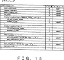
図15はpicture_headr()関数のシンタックスを説明するための図である。このpicture_headr()関数によって定義されたデータエレメントは、picture_start_code、temporal_reference、picture_coding_type、vbv_delay、full_pel_forward_vector、forward_f_code、full_pel_backward_vector、backward_f_code、extra_bit_picture、及びextra_information_pictureである。
具体的には、picture_start_codeは、ピクチャレイヤの開始同期コードを表すデータである。temporal_referenceは、ピクチャの表示順を示す番号でGOPの先頭でリセットされるデータである。picture_coding_typeは、ピクチャタイプを示すデータである。
vbv_delayは、VBVバッファの初期状態を示すデータであって、各ピクチャ毎に設定されている。送信側システムから受信側システムに伝送された符号化エレメンタリーストリームのピクチャは、受信側システムに設けられたVBVバッファにバッファリングされ、DTS(Decoding Time Stamp)によって指定された時間に、このVBVバッファから引き出され(読み出され)、デコーダに供給される。vbv_delayによって定義される時間は、復号化対象のピクチャがVBVバッファにバッファリングされ始めてから、符号化対象のピクチャがVBVバッファから引き出される時間、つまりDTSによって指定された時間までを意味する。本発明の符号化ストリームスプライシング装置においては、このピクチャヘッダに格納されたvbv_delayを使用することによって、VBVバッファのデータ占有量な不連続にならないシームレスなスプライシングを実現するようにしている。詳しくは後述する。
full_pel_forward_vectorは、順方向動きベクトルの精度が整数単位か半画素単位かを示すデータである。forward_f_codeは、順方向動きベクトル探索範囲を表すデータである。full_pel_backward_vectorは、逆方向動きベクトルの精度が整数単位か半画素単位かを示すデータである。backward_f_codeは、逆方向動きベクトル探索範囲を表すデータである。extra_bit_pictureは、後続する追加情報の存在を示すフラグである。このextra_bit_pictureが「1」の場合には、次にextra_information_pictureが存在し、extra_bit_pictureが「0」の場合には、これに続くデータが無いことを示している。extra_information_pictureは、規格において予約された情報である。
図16は、picture_coding_extension()関数のシンタックスを説明するための図である。このpicture_coding_extension()関数によって定義されたデータエレメントとは、extension_start_code、extension_start_code_identifier、f_code[0][0]、f_code[0][1]、f_code[1][0]、f_code[1][1]、intra_dc_precision、picture_structure、top_field_first、frame_predictive_frame_dct、concealment_motion_vectors、q_scale_type、intra_vlc_format、alternate_scan、repeat_firt_field、chroma_420_type、progressive_frame、composite_display_flag、v_axis、field_sequence、sub_carrier、burst_amplitude、及びsub_carrier_phaseから構成される。
extension_start_codeは、ピクチャレイヤのエクステンションデータのスタートを示す開始コードである。extension_start_code_identifierは、どの拡張データが送られるかを示すコードである。f_code[0][0]は、フォアード方向の水平動きベクトル探索範囲を表すデータである。f_code[0][1]は、フォアード方向の垂直動きベクトル探索範囲を表すデータである。f_code[1][0]は、バックワード方向の水平動きベクトル探索範囲を表すデータである。f_code[1][1]は、バックワード方向の垂直動きベクトル探索範囲を表すデータである。intra_dc_precisionは、DC係数の精度を表すデータである。picture_structureは、フレームストラクチャかフィールドストラクチャかを示すデータである。フィールドストラクチャの場合は、上位フィールドか下位フィールドかもあわせて示すデータである。
top_field_firstは、フレームストラクチャの場合、最初のフィールドがトップフィールドであるのかボトムフィールドであるのかを示すフラグである。frame_predictive_frame_dctは、フレーム・ストラクチャの場合、フレーム・モードDCTの予測がフレーム・モードだけであることを示すデータである。concealment_motion_vectorsは、イントラマクロブロックに伝送エラーを隠蔽するための動きベクトルがついていることを示すデータである。q_scale_typeは、線形量子化スケールを利用するか、非線形量子化スケールを利用するかを示すデータである。intra_vlc_formatは、イントラマクロブロックに、別の2次元VLCを使うかどうかを示すデータである。alternate_scanは、ジグザグスキャンを使うか、オルタネート・スキャンを使うかの選択を表すデータである。
repeat_first_fieldは、復号化時にリピートフィールドを生成するか否かを示すフラグであって、復号化時の処理において、repeat_first_fieldが「1」の場合にはリピートフィールドを生成し、repeat_first_fieldが「0」の場合にはリピートフィールドを生成しないという処理を行なう。chroma_420_typeは、信号フォーマットが4:2:0の場合、次のprogressive_frameと同じ値、そうでない場合は0を表すデータである。progressive_frameは、このピクチャが、順次走査できているかどうかを示すデータである。composite_display_flagは、ソース信号がコンポジット信号であったかどうかを示すデータである。v_axisは、ソース信号が、PALの場合に使われるデータである。field_sequenceは、ソース信号が、PALの場合に使われるデータである。sub_carrierは、ソース信号が、PALの場合に使われるデータである。burst_amplitudeは、ソース信号が、PALの場合に使われるデータである。sub_carrier_phaseは、ソース信号が、PALの場合に使われるデータである。
extension_and_user_data(2)関数は、図13に示したように、符号化ビットストリーム中にエクステンションスタートコードextension_start_codeが存在する場合には、extension_data()関数によって定義されるデータエレメントが記述されている。但し、ビットストリーム中にエクステンションスタートコードが存在しない場合にはextension_data()関数によって定義されるデータエレメントはビットストリーム中には記述されていない。このextension_data()関数によって定義されているデータエレメントの次には、ビットストリーム中にユーザデータスタートコードuser_data_start_codeが存在する場合には、user_data()関数によって定義されるデータエレメントが記述されている。
図17は、picture_data()関数のシンタックスを説明するための図である。このpicture_data()関数によって定義されるデータエレメントは、slice()関数によって定義されるデータエレメントである。但し、ビットストリーム中に、slice()関数のスタートコードを示すslice_start_codeが存在しない場合には、このslice()関数によって定義されるデータエレメントはビットストリーム中に記述されていない。
slice()関数は、スライスレイヤに関するデータエレメントを記述するための関数であって、具体的には、slice_start_code、slice_quantiser_scale_code、intra_slice_flag、intra_slice、reserved_bits、extra_bit_slice、extra_information_slice、及びextra_bit_slice等のデータエレメントと、macroblock()関数によって定義されるデータエレメントを記述するための関数である。
slice_start_codeは、slice()関数によって定義されるデータエレメントのスタートを示すスタートコードである。slice_quantiser_scale_codeは、このスライスレイヤに存在するマクロブロックに対して設定された量子化ステップサイズを示すデータである。しかし、各マクロブロック毎に、quantiser_scale_codeが設定されている場合には、各マクロブロックに対して設定されたmacroblock_quantiser_scale_codeのデータが優先して使用される。intra_slice_flagは、ビットストリーム中にintra_slice及びreserved_bitsが存在するか否かを示すフラグである。intra_sliceは、スライスレイヤ中にノンイントラマクロブロックが存在するか否かを示すデータである。スライスレイヤにおけるマクロブロックのいずれかがノンイントラマクロブロックである場合には、intra_sliceは「0」となり、スライスレイヤにおけるマクロブロックの全てがノンイントラマクロブロックである場合には、intra_sliceは「1」となる。reserved_bitsは、7ビットのデータであって「0」の値を取る。extra_bit_sliceは、符号化ストリームとして追加の情報が存在することを示すフラグであって、次にextra_information_sliceが存在する場合には「1」に設定される。追加の情報が存在しない場合には「0」に設定される。
macroblock()関数は、マクロブロックレイヤに関するデータエレメントを記述するための関数であって、具体的には、macroblock_escape、macroblock_address_increment、及びmacroblock_quantiser_scale_code等のデータエレメントと、macroblock_modes()関数、及びmacroblock_vecters(s)関数によって定義されたデータエレメントを記述するための関数である。
macroblock_escapeは、参照マクロブロックと前のマクロブロックとの水平方向の差が34以上であるか否かを示す固定ビット列である。参照マクロブロックと前のマクロブロックとの水平方向の差が34以上の場合には、macroblock_address_incrementの値に33をプラスする。macroblock_address_incrementは、参照マクロブロックと前のマクロブロックとの水平方向の差を示すデータである。もし、このmacroblock_address_incrementの前にmacroblock_escapeが1つ存在するのであれば、このmacroblock_address_incrementの値に33をプラスした値が、実際の参照マクロブロックと前のマクロブロックとの水平方向の差分を示すデータとなる。macroblock_quantiser_scale_codeは、各マクロブロック毎に設定された量子化ステップサイズである。各スライスレイヤには、スライスレイヤの量子化ステップサイズを示すslice_quantiser_scale_codeが設定されているが、参照マクロブロックに対してmacroblock_quantiser_scale_codeが設定されている場合には、この量子化ステップサイズを選択する。
次に、図18及び図19を参照して、トランスポートストリームパケットの構造及びトランスポートストリームパケットのシンタックスについて詳しく説明する。
トランスポートストリームパケットは、4バイトのヘッダと、各種のデータ及びデータエレメントを格納するための184バイトのペーロード部とから構成されている。
トランスポートストリームパケットのヘッダ部は、sync_byte、transport_error_indicator、payload_unit_start_indicator、transport_priority、PID、transport_scrambling_control、adaptation_field_control、continuity_counter、及びadaptation_field等の各種フィールドから構成されている。
sync_byteとは、ビットストリーム中から同期パターンを検出するための固定の8ビットのフィールドである。値は‘01000111’(Ox47)の固定値で定義され、このストリーム中のこのビットパターンを検出することによって、同期を検出することができる。
transport_error_indicatorは、1ビットのフラグである、「1」に設定されると、少なくとも1ビットの訂正できないビットエラーがトランスポートストリームパケットに存在することを示す。
payload_unit_start_indicatorは、1ビットのフラグである。ビデオ/オーディオデータ等のエレメンタリーデータまたはプログラム仕様情報(PSI)を伝送するトランスポートストリームパケットに対して規範的な意味を有するデータである。トランスポートストリームパケットのペイロードがエレメンタリーデータを含む場合、payload_unit_start_indicatorは、次の意味を有する。payload_unit_start_indicatorが「1」の場合には、このトランスポートストリームパケットのペイロードの最初に、エレメンタリーデータが挿入されていることを示し、payload_unit_start_indicatorが「0」の場合には、このトランスポートストリームパケットのペイロードの最初に、エレメンタリーデータが挿入されていないことを示す。もし、payload_unit_start_indicatorが「1」にセットされると、ただ一つのPESパケットが任意のトランスポートストリームパケットで開始することを示す。一方、トランスポートストリームパケットのペイロードがPSIデータを含む場合、payload_unit_start_indicatorは、次の意味を有する。もし、トランスポートパケットがPSIセクションの第1バイトを伝送する場合、payload_unit_start_indicatorは「1」となる。もし、トランスポートストリームパケットがPSIセクションの第1バイトを伝送していない場合、payload_unit_start_indicatorは「0」となる。尚、トランスポートストリームパケットがヌルパケットの場合にも、payload_unit_start_indicatorは「0」となる。
transport_priorityは、トランスポートパケットの優先度を示す1ビットの識別子である。このtransport_priorityが「1」に設定されると、このトランスポートパケットは、同一のパケット識別子PIDをもつパケットであって、このtransport_priorityが「1」でないパケットより優先度が高いことを示している。例えば、このtransport_priorityのパケット識別子を設定することによって、一つのエレメンタリーストリーム内において任意のパケットに優先度をつけることができる。
transport_scrambling_controlは、トランスポートストリームパケットペイロードのスクランブリングモードを示す2ビットのデータである。スクランブリングモードとは、ペイロードに格納されたデータがスクランブされているか否か及びそのスクランブルの種類を示すためのモードである。トランスポートストリームパケットヘッダ、およびアダブテーションフィールドは、スクランブルキーKsによってスクランブルされてはならないように規格化されている。よって、このtransport_scrambling_controlによって、トランスポートストリームパケットペイロードに格納されたデータがスクランブルされているか否かを判断することができる。
adaptation_field_controlは、このトランスポートストリームのパケットヘッダにアダプテーションフィールド及び/又はペイロードがくることを示す2ビットのデータである。具体的には、パケットヘッダにペイロードデータのみが配置される場合には、このadaptation_field_controlは「01」となり、パケットヘッダにアダプテーションフィールドのみが配置される場合には、このadaptation_field_controlは「10」となり、パケットヘッダにアダプテーションフィールドとペイロードとが配置される場合には、このadaptation_field_controlは「11」となる。
continuity_counterは、連続して伝送された同じPIDをもつパケットが、伝送途中で一部欠落又は捨てられか否かを示すためのデータである。具体的には、continuity_counterは、同一のPIDを有する各トランスポートストリームパケットごとに増加する4ビットのフィールドである。但し、このcontimlty_comterがカウントされるときは、パケットヘッダにアダムテーションフィールドが配置されている場合である。
adaptation_field( )は、個別ストリームに関する付加情報やスタッフィングバイト等をオプションとして挿入するためのフィールドである。このアダプテーションフィールドによって、個別ストリームの動的な状態変化に関するあらゆる情報をデータと一緒に伝送することができる。
図19は、adaptation_field( )のシンタックスを説明するための図である。このadaptation_field( )は、adaptation_field_length、discontinuity_counter、randam_access_indicator、elemntary_stream_priority_indicator、OPCR_flag、splicing_point_flag、transport_private_data_flag、adaptation_field_extension_flag、program_clock_reference(PCR)、original_program_clock_reference(OPCR)、splice_countdown、、transport_private_data_length、private_data、adaptation_field_extension_length、ltw_flag(leagal_time_window_flag)、piecewise_rate_flag、及びseamless_splice_flag等の各種フィールドから構成されている。
adaptation_field_lengthは、このadaptation_field_lengthの次に続くアダプテーションフィールドのバイト数を示すデータである。adaptation_field_controlが「11」の場合には、adaptation_field_lengthは0から182ビットであって、adaptation_field_controlが「10」の場合には、adaptation_field_lengthは183ビットとなる。尚、トランスポートストリームのペイロードを満たすだけのエレメンタリーストリームが無い場合には、ビットを満たすためのスタッフィング処理が必要となる。
discontinuity_counterは、同じPIDを有する複数のパケットの途中において、システムクロックリファレンス(SCR)がリセットされ、システムクロックリファレンスが不連続になっているか否かを示すデータである。もし、システムクロックリファレンスが不連続の場合には、このdiscontinuity_counterは「1」となり、システムクロックリファレンスが連続している場合には、このdiscontinuity_counterは「0」となる。尚、このシステムクロックリファレンスとは、ビデオ及びオーディオのデコードするためのMPEGデコーダにおいて、デコーダ側のシステムタイムクロックの値をエンコーダ側において意図したタイミングに設定するための参照情報である。
randam_access_indicatorは、ビデオのシーケンスヘッダ又はオーディオのフレームの始まりを示すデータである。つまり、このrandam_access_indicatorは、データエレメントのランダムアクセスを行うときに、ビデオ又はオーディオのアクセスポイント(フレームの始まりのこと)であることを示すためのデータである。
elemntary_stream_priority_indicatorは、同一のPIDを有するパケットにおいて、このトランスポートストリームパケットのペイロード中で伝送されるエレメンタリーストリームデータの優先度を示すデータである。例えば、エレメンタリーストリームがビデオデータが、そのビデオデータがイントラ符号化されている場合に、elemntary_stream_priority_indicatorが[1」にセットされる。それに対して、インター符号化されているビデオデータを含んだトランスポートストリームのelemntary_stream_priority_indicatorは、「0」にセットされる。
PCR_flagは、アダプテーションフィールド内にPCR(program_clock_refrence)データが存在するか否かを示すデータでる。アダプテーションフィールド内にPCRデータが存在する場合には、PCR_flagが「1」にセットされ、PCRデータが存在しない場合には、PCR_flagが「0」にセットされる。尚、このPCRデータとは、受信機側のデコーダにおいて、伝送されたデータをデコードするデコード処理のタイミングを得るために使用されるデータである。
OPCR_flagは、アダプテーションフィールド内にOPCR(original_program_clock_refrence)データが存在するか否かを示すデータでる。アダプテーションフィールド内にOPCRデータが存在する場合には、OPCR_flagが「1」にセットされ、OPCRデータが存在しない場合には、OPCR_flagが「0」にセットされる。このOPCRデータとは、スプラインシング処理等によって、複数のオリジナルトランスポートストリームから1つのトランスポートストリームを再構築したときのに使用されるデータであって、あるオリジナルトランスポートストリームのPCRデータを表わすデータである。
splicing_point_flagは、トランスポートレベルでの編集ポイント(スプライスポイント)を示すためのsplice_countdounがアダプテーションフィールド内に存在するか否かを示すデータである。アダプテーションフィールド内にsplice_countdounが存在する場合には、このsplicing_point_flagは「1」であって、アダプテーションフィールド内にsplice_countdounが存在する場合には、このsplicing_point_flagは「0」である。
transport_private_data_flagは、アダプテーションフィールド内に、任意のユーザデータを記述するためのプライベートが存在するか否かを示すためのデータである。アダプテーションフィールド内にプライベートが存在する場合には、このtransport_private_data_flagは「1」にセットされ、アダプテーションフィールド内にプライベートが存在しない場合には、このtransport_private_data_flagは「0」にセットされる。
adaptation_field_extension_flagは、アダプテーションフィールド内に、拡張フィールド存在するか否かを示すためのデータである。アダプテーションフィールド内に拡張フィールドが存在する場合には、このadaptation_field_extension_flagは「1」にセットされ、アダプテーションフィールド内に拡張フィールドが存在しない場合には、このadaptation_field_extension_flagは「0」にセットされる。
program_clock_reference(PCR)は、送信側とクロックの位相に対して受信機側のクロックの位相を同期させるときに参照する基準クロックである。このPCRデータには、トランスポートパケットが生成された時間が格納されている。このPCRは、、33ビットのprogram_clock_reference_baseと9ビットのprogram_clocLreference_extensionとの42ビットから構成されるデータである。program_clocLreference_extensionによって0〜299までのシステムクロックをカウントし、299から0にリセットされる際のキャリーによって、program_clock_reference_baseに1ビットを加算することによって、24時間をカウントすることができる。
original_program_clock_reference(OPCR)は、あるトランスポートストリームから単一プログラムのトランスポートストリームを再構成するときに使用されるデータである。単一プログラムドランスボートストリームが完全に再構成された場合、このoriginal_program_clock_referenceはprogram_clock_referenceにコピーされる。
splice_countdownは、同一PIDのトランスポートストリームパケットにおいて、トランスポートストリームパケットレベルで編集可能(スプライシング処理可能)なポイントまでのパケットの数を示すデータである。従って、編集可能なスプライシングポイントのトランスポートストリームパケットでは、splice_countdownは「0」である。splice_countdownが「0」になるトランスポートパケットで、トランスポートストリームパケットペイロードの最終バイトは、符号化されたピクチャの最後のバイトとすることによって、スプライシング処理が可能となる。
このスプライシング処理とは、トランスポートレベルで行われる2つの異なるエレメンタリーストリームを連結し、1つの新しいトランスポートストリームを生成する処理のことである。そして、スプライシング処理として、復号の不連続性を発生しないシームレススプライスと、復号の不連続性を引き起こすノンシームレススプライスとに分けることができる。符号の不連続性を発生しないとは、新しく後ろにつなげられたストリームのアクセスユニットの復号時間と、スプライス前の古いストリームのアクセスユニットの復号時間と間の矛盾が無いことを示し、符号の不連続性を発生するとは、新しく後ろにつなげられたストリームのアクセスユニットの復号時間に対して、スプライス前の古いストリームのアクセスユニットの復号時間の矛盾が生じることを示している。
transport_private_data_lengthは、アダプテーションフィールドにおけるプライデートデータのバイト数を示すデータである。
private_dataは、規格では特に規定されておらず、アダプテーションフィールドにおいて任意のユーザデータを記述することができるフィールドである。
adaptation_field_extension_lengthは、アダプテーションフィールドにおけるアダプテーションフィールドエクステンションのデータ長を示すデータである。
ltw_flag(leagal_time_window_flag)は、アダプテーションフィールドにおいて表示ウインドウのオフセット値を示すltw_offsetが存在するか否かを示すデータでる。
piecewise_rate_flagは、アダプテーションフィールドにおいてpiecewise_rateが存在するか否かを示すデータでる。
seamless_splice_flagは、スプライシングポイントが、通常のスプライシングポイントか、シームレススプライシングポイントであるかを示すデータである。このseamless_splice_flagが「0」の時は、スプライシングポイントが通常のスプライシングポイントであることを示し、このseamless_splice_flagが「1」の時は、スプライシングポイントがシームレススプイシングポイントであることを示している。通常のスプライシングポイントとは、スプライシングポイントがPESパケットの区切りに存在する場合であって、このスプライシングポイントの直前のスプライシングパケットがアクセスユニットで終了し、次の同じPIDを有するトランスポートパケットがPESパケットのヘッダで開始している場合である。これに対して、シームレススプライシングポイントとは、PESパケットの途中にスプライシングポイントがある場合であって、新しく後ろにつなげられたストリームのアクセスユニットの復号時間と、スプライス前の古いストリームのアクセスユニットの復号時間との間に矛盾が無いようにするために、古いストリームの特性の一部を、新しいストリームの特性として使う場合である。
次に、本局30から伝送されたきたストリームSTOLDと地方局40において生成されたストリームSTNEWとをスプライシングするスプライシング処理について、図20から図23を参照して説明する。
図20は、図7において説明した地方局40の制御をよりわかりやすく説明するために、複数チャンネルうちのある1チャンネルのみを残して、他のチャンネルを省略した図である。本発明においては、スプライシング処理に関する実施例として3つのスプライシング処理に関する実施例を有している。以下に、第1、第2及び第3のスプライシング処理に関する実施例を順に説明する。
第1のスプライシング処理に関する実施例は、伝送プログラムの符号化ストリームSTOLDが本局30から伝送されてくる前に、新しく挿入されるコマーシャルCM’の符号化ストリームSTNEWが既に生成されている場合に行われるスプライシング処理に関する実施例である。つまり、伝送プログラムにおけるコマーシャルCMの符号化ストリームSTOLD部分に、既に前もって符号化されていコマーシャルCM1’のストリームを挿入する場合である。通常、コマーシャルというものは何度も繰り返して放映されるので、その度にコマーシャルのビデオデータを符号化するのでは効率的ではない。そこで、地方向けのコマーシャルCM1’のビデオデータを符号化し、その符号化ストリームTSNEWをストリームサーバ49に予め記憶しておく。そして、本局30から置換えられるコマーシャルCM1の符号化ストリームSTOLDが伝送されてきたときに、このストリームサーバ49から地方向けのコマーシャルCM1’の符号化ストリームSTNEWを再生することによって、同じコマーシャルを何度も符号化する処理を省くことができる。このような場合に、以下に具体的に説明する第1のスプライシング処理が行われる。
まず地方局40において、伝送プログラムのコマーシャルCM1の部分に置換えられる地方向けのコマーシャルCM1’を符号化し、符号化ストリームSTNEWをストリームサーバ49に格納する初期処理について説明する。放送システムコントローラ41は、伝送プログラムのコマーシャルCMの部分に置換えられるコマーシャルCM1’のビデオデータを再生するようにCMサーバ47を制御する。そして、エンコーダ481は、CMサーバ47から再生されたベースバンドのビデオデータを受取り、このビデオデータの各ピクチャの符号化難易度(Difficulty)Diをエンコーダコントローラ480に供給する。エンコーダコントローラ480は、図8において説明したエンコーダコントローラ350と同じように、エンコーダ481が適切な符号化ビットを発生するようにエンコーダ481に対してターゲットビットレートRiを供給する。エンコーダ481は、エンコーダコントローラ480から供給されたターゲットビットレートRiに基いて符号化処理を行なうことによって、最適なビットレートの符号化エレメンタリーストリームSTNEWを生成することができる。エンコーダ481から出力された符号化エレメンタリーストリームSTNEWは、ストリームサーバ49に供給される。ストリームサーバ49は、符号化エレメンタリーストリームをストリームの状態のまま、ランダムアクセス可能な記録媒体に記録する。これで、符号化ストリームSTNEWをストリームサーバ49に格納する初期処理は終了する。
次に、本局から伝送されてきた伝送プログラムの符号化ストリームSTOLDと、上述した初期処理によってストリームサーバ49に格納された符号化ストリームSTNEWとをスプライシングするスプライシング処理について説明する。
本局30から伝送されてきた符号化ストリームSTOLDは、ストリーム変換回路44においてトランスポートストリームの形式からエレメンタリーストリームの形式に変換される。エレメンタリーストリームの形式に変換された符号化ストリームSTOLDは、ストリームスプライサ50に供給される。
ストリームスプライサ50は、図20に示されているように、スプライスコントローラ500、スイッチ回路501、ストリーム解析回路502、ストリームプロセッサ503、及びスプライシング回路504を備えている。
この第1のスプライシング処理に関する実施例では、スプライスコントローラ500は、スイッチ回路501の入力端子を「a」に切換え、ストリームサーバ49から供給されたエレメンタリーストリームSTNEWをストリーム解析回路502に供給する。
ストリーム解析回路502は、符号化ストリームSTOLD及び符号化ストリームSTNEWのシンタックスを解析する回路である。具体的には、ストリーム解析回路502は、図10及び図15に開示された符号化ストリームのシンタックスから理解できるように、符号化ストリームSTOLD中に記述された32ビットのpicture_start_codeを探すことによって、ストリーム中においてピクチャヘッダに関する情報が記述された場所を把握する。次に、ストリーム解析回路502は、picture_start_codeの11ビット後から始まる3ビットのpicture_coding_typeを見つけることによって、ピクチャタイプを把握すると共に、この3ビットのpicture_coding_typeの次に記述された16ビットのvbv_delayから、符号化ピクチャのvbv_delayを把握することができる。
さらに、ストリーム解析回路502は、図10及び図15に開示された符号化ストリームのシンタックスから理解できるように、符号化ストリームSTOLD及び符号化ストリームSTNEW中に記述された32ビットのextension_start_codeを探すことによって、ストリーム中においてピクチャコーディングエクステンションに関する情報が記述された場所を把握する。次に、ストリーム解析回路502は、picture_start_codeの25ビット後から記述された1ビットのtop_field_firstと、そのtop_field_firstの6ビット後から記述されたrepeat_first_fieldとを探すことによって、符号化ピクチャのフレーム構造を把握することができる。例えば、符号化ピクチャの「top_field_first」が「1」である場合には、トップフィールドがボトムフィールドよりも時間的に早いフレーム構造であることを示し、「top_field_first」が「0」の場合には、トップフィールドがボトムフィールドよりも時間的に早いフレーム構造であることを示す。また、符号化ストリーム中のフラグ「top_field_first」が「0」であって且つ「repeat_first_field」が「1」の場合には、復号化時にトップフィールドからリピートフィールドが生成されるようなピクチャ構造であることを示し、符号化ストリーム中のフラグ「top_field_first」が「0」であって且つ「repeat_first_field」が「1」の場合には、復号化時にボトムフィールドからリピートフィールドが生成されるようなピクチャ構造を有していることを示している。
上述した、picture_coding_type、vbv_delay、top_field_first及びrepeat_first_fieldは、各ピクチャ毎に符号化ストリームから抽出され、スプライスコントローラ500に供給される。ストリーム解析回路502に供給されたエレメンタリーストリームSTOLD及びエレメンタリーストリームSTNEWは、そのままエレメンタリーストリームSTOLD及びエレメンタリーストリームSTNEWとしてストリームプロセッサ503に供給される。
さらに、ストリーム解析回路502は、供給されたストリームSTOLDとストリームSTNEWのビット数をカウントするためのカウンタを備えており、このカウント値と各ピクチャの発生ビット量とに基いて、各ピクチャ毎にVBVバッファのデータ残量をシュミレーションするようにしている。ストリーム解析回路502において演算された各ピクチャ毎のVBVバッファのデータ残量も、スプライスコントローラ500に供給される
ストリームプロセッサ503は、ストリームSTOLDとストリームSTNEWとをスプライシングすることによって生成されるスプライスドストリームSTSPLがシームレスなストリームとなるように、このストリームSTOLD及びストリームSTNEWのストリーム構造、データエレメント及びフラグを変更するための回路である。このストリームプロセッサ503の具体的な処理を、図21を参照して説明する。
図21Aは、本局30から供給されたオリジナルストリームSTOLDと、そのストリームSTOLDのVBVバッファのデータ占有量の軌跡を示す図であって、図21Bは、ストリームサーバ49に記憶された差し替えストリームSTNEWと、そのストリームSTNEWのVBVバッファのデータ占有量の軌跡を示す図であって、図21Bは、スプライシングポイントSP1及びSP2において、ストリームSTOLDとストリームSTNEWとをスプライシングしたスプライスドストリームSTSPLと、そのスプライスドストリームSTSPLのVBVバッファのデータ占有量の軌跡を示す図である。尚、図21Aにおいて、DTS(デコーディングタイムスタンプ)を示し、SP1vbvは、VBVバッファのデータ占有量の軌跡上における第1のスプライシングポイントを示し、SP2vbvは、VBVバッファデータ占有量の軌跡上における第2のスプライシングポイントを示し、VO(I6)は、ピクチャB5がVBVバッファから引き出されたときにVBVバッファ上にバッファリングされているピクチャI6のデータ量を示し、GB(I6)は、ピクチャI6の発生ビット量を示し、VD(I6)は、ピクチャI6のvbv_delayの値を示し、VO(B7)は、ピクチャI6がVBVバッファから引き出されたときにVBVバッファ上にバッファリングされているピクチャB7のデータ量を示し、GB(B11)は、ピクチャB11の発生ビット量を示し、VD(I12)は、ピクチャI12のvbv_delayの値を示し、VO(I12)は、ピクチャB11がVBVバッファから引き出されたときにVBVバッファ上にバッファリングされているピクチャI12のデータ量を示している。また、図21Bにおいて、GB(I6’)は、ピクチャI6’の発生ビット量を示し、VD(I6’)は、ピクチャI6’のvbv_delayの値を示し、VO(I6’)は、VBVにおける第1のスプライシングポイントSP1vbvにおけるピクチャI6’のVBVバッファにバッファリングされているデータ量を示し、GB(B11’)は、ピクチャB11’の発生ビット量を示し、VO(I12’)は、VBVにおける第2のスプライシングポイントSP2vbvにおけるピクチャB12’のVBVバッファにバッファリングされているデータ量を示している。また、図21Cにおいて、GB(I6”)は、スプライスドストリームSTSPLがシームレスなストリームとなるようにストリーム処理されたピクチャI6”の発生ビット量を示し、VD(I6”)は、ピクチャI6”のvbv_delayの値を示し、GB(B11”)は、スプライスドストリームSTSPLがシームレスなストリームとなるようにストリーム処理されたピクチャB11”の発生ビット量を示している。
オリジナルストリームSTOLDは本局30において符号化されたストリームであって、差し替えストリームSTNEWは地方局40において符号化されたストリームであるので、ストリームSTOLDとストリームSTNEWとは、それぞれのビデオエンコーダで全く関係無く符号化されたストリームである。つまり、ストリームSTOLDにおける最初のピクチャI6のvbv_delayの値VD(I6)と、ストリームSTNEWにおける最初のピクチャ16’のvbv_delayの値VD(I6’)とは同じ値ではない。つまり、このような場合には、VBVバッファにおけるストリームスプライスポイントSP1vbvのタイミングにおいて、オリジナルストリームSTOLDのVBVハッファのデータ占有量VO(I6)と、差し替えストリームSTNEWのVBVバッファのデータ占有量VO(I6’)とは異なってしまう。
つまり、本発明の背景技術において説明したように、スプライスポイントSP1において、ストリームSTOLDとストリームSTNEWとを単純にスプライスしてしまうと、単純にスプライスされたストリームのVBVバッファのデータ占有量が不連続になるか又はオーバーフロー/アンダーフローしてしまう。
そこで、ストリームスプライサ50では、ストリーム解析回路502においてストリームSTOLD及びストリームSTNEWから抽出されたデータエレメントに基いて、スプライスドストリームSTSPLがスプライスポイントにおいてシームレスなストリームとなるように、ストリームプロセッサ503において、供給されたストリームSTOLD及びストリームSTNEWのストリーム構造に関してストリーム処理を行なっている。その処理を以下に説明する。
スプライスコントローラ500は、ストリームSTOLDに関するデータエレメントとして、各ピクチャ毎に、picture_coding_type、vbv_delay、top_field_first及びrepeat_first_field等の情報、各ピクチャにおける発生ビット量、各ピクチャにおけるVBVバッファのデータ占有量をストリーム解析回路502から受け取る。図21においては、例えば、ピクチャI6におけるvbv_delayの値をVD(I6)と表わし、ピクチャI6における発生ビット量をGB(I6)と表わし、ピクチャI6におけるVBVバッファのデータ占有量をVO(I6)というように表わしている。
次に、スプライスポイントSP1におけるスプライスコントローラ500とストリームプロセッサ503のVBVバッファに関する処理について説明する。
まず、スプライスコントローラ500は、スプライシングポイントSP1における、オリジナルストリームSTOLDのピクチャI6のvbv_delayの値VD(I6)と、差し替えストリームSTNEWのピクチャI6’のvbv_delayの値VD(I6’)とが異なると判断した場合には、差し替えストリームSTNEW中に記述されたピクチャI6’のvbv_delayの値をVD(I6’)からVD(I6)に書き換えるようにストリームプロセッサ503に指示を与える。
ストリームプロセッサ503は、スプライスコントローラ500からの指示に従って、差し替えストリームSTNEWのピクチャヘッダ中に記述された16ビットのvbv_delayの値をVD(I6’)からVD(I6)に書き換える。
ここで、単に、差し替えストリームSTNEWにおけるvbv_delayの値をVD(I6’)からVD(I6)に書き換え、この書き換えたvbv_delayに従ってVBVバッファからビットストリームを引き出そうとすると、ピクチャI6’の発生ビット量が足りないので、VBVバッファがアンダーフローしてしまう。そこで、スプライスコントローラ500は、差し替えストリームSTNEWのピクチャI6’の発生ビット量GB(I6’)が、シームレスなスプライスドストリームSTSPLのピクチャI6”の発生ビット量GB(I6”)になるように、差し替えストリームSTNEWのピクチャI6’のに対してスタッフィングバイトを挿入する処理を行なう。このスタッフィングバイトとは、「0」のダミービットから構成されるデータである。
スタッフィングバイトを挿入する処理を行うために、スプライスコントローラ500は、ストリームSTOLDにおけるピクチャI6及びピクチャB7に関する情報として受け取った発生ビット量GB(I6)、VBVバッファのデータ占有量VO(I6)、及びストリームSTNEWにおけるピクチャI6’に関する情報として受け取った発生ビット量GB(I6’)、VBVバッファのデータ占有量VO(I6’)を使用して、挿入すべきスタッフィングバイトのデータ量を演算する。具体的には、下記の式(2)に基いてスタッフィングバイトSB1[byte]が演算される。
SB1[byte]={GB(I6”)−GB(I6’)}/8
={GB(I6)−GB(I6’)+VO(B7)−VO(B7’)}/8 … (2)
スプライスコントローラ500は、上式(2)に従って演算したスタフィングバイトSB1を、ストリームSTNEWの中に挿入するようにストリームプロセッサ503を制御する.
ストリームプロセッサ503は、スプライスコントローラ500からの指令に従って、スタフィングバイトSB1を、ストリームSTNEWの中に記述する。スタッフィングバイトをストリーム中に記述する位置としては、符号化ストリームSTNEWのピクチャI6のピクチャヘッダのスタートコードの前が最も望ましいが、他のスタートコードの前であっても問題はない。
以上が、スプライスポイントSP1におけるスプライスコントローラ500とストリームプロセッサ503のVBVバッファに関する制御である。
次に、スプライスポイントSP2におけるスプライスコントローラ500とストリームプロセッサ503のVBVバッファに関する制御について説明する。
単に、スプライスポイントSP2において、ストリームSTNEWとストリームSTOLDとをスプライシングしたとすると、ストリームSTNEWの最後のピクチャB11’の発生ビット量GB(B11’)が足りないので、ストリームSTNEWの最初のピクチャI12のVBVバッファのデータ占有量の軌跡と連続にならない。その結果、VBVバッファがアンダーフロー又はオーバーフローしてしまう。
そこで、スプライスコントローラ500は、VBVバッファにおけるスプライスポイントSP2vbvにおいて、VBVバッファの軌跡が連続になるように、ストリームSTNEWの最後のピクチャB11’の発生符号量GB(B11’)が、図21CのピクチャB11”の発生符号量GB(11”)となるように、ストリームSTNEW中にスタッフィングバイトを挿入する処理を行なう。
スタッフィングバイトを挿入する処理を行うために、スプライスコントローラ500は、ストリームSTOLDにおけるピクチャI12に関する情報として受け取ったVO(I12)、ストリームSTNEWの最後のピクチャ11’の発生ビット量GB(B11’)、及びストリームSTNEWのピクチャ12’のVBVバッファのデータ占有量VO(I12’)を使用して、挿入すべきスタッフィングバイトのデータ量を演算する。尚、具体的には、下記の式(2)に基いてスタッフィングバイトSB2[byte]が演算される。
SB2[byte]={GB(B11”)−GB(B11’)}/8
={VO(I12’)−VO(I12)}/8 … (3)
尚、データ占有量VO(I12’)とは、最後のピクチャB11’をVBVバッファから引き出した後のストリームSTNEWに関するVBVバッファのデータ占有量であると言い換えることができ、ストリームSTNEWのビット数をカウントすることによってVBVの軌跡を把握しているストリーム解析回路502によって、容易にこのデータ占有量VO(I12’)検出することができる。
このスプライスコントローラ500は、上式(3)に従って演算したスタフィングバイトSB2を、ストリームSTNEW中に挿入するようにストリームプロセッサ503を制御する.
ストリームプロセッサ503は、スプライスコントローラ500からの指令に従って、スタフィングバイトSB2を、ストリームSTNEWのピクチャB11’に関する情報として記述する。スタッフィングバイトをストリーム中に記述する位置としては、符号化ストリームSTNEWのピクチャB11’のピクチャヘッダのスタートコードの前が最も望ましい。
以上が、スプライスポイントSP2におけるスプライスコントローラ500とストリームプロセッサ503のVBVバッファに関する制御である。
図22を参照して、スプライスポイントSP1におけるスプライスコントローラ500とストリームプロセッサ503のtop_field_first及びrepeat_first_field等のフラグに関する第1の処理例を説明する。
図22Aは、本局30において制作されたプログラム1とコマーシャルCM1とプログラム2から構成されるテレビ番組PGOLDのフレーム構造と、そのテレビ番組PGOLDを符号化したときの符号化ストリームSTOLDを示している図である。図22Bは、地方局40において制作された差し替えコマーシャルCM1’のフレーム構造と、その差し替えコマーシャルCM1’をを符号化したときの符号化ストリームSTNEWを示している図である。図22Cは、オリジナルストリームSTOLDと差し替えストリームSTNEWとをスプライシングしたときに生成されるスプライスドストリームSTSPLと、そのスプライスドストリームSTSPLをデコードしたときのフレーム構造を示している図である。
スプライスコントローラ500は、ストリーム解析回路502から供給されたストリームSTOLDにおけるコマーシャルCM1の各ピクチャのtop_field_firstと、差し替えストリームSTNEWにおけるコマーシャルCM1’のtop_field_firstとを比較する。もし、ストリームSTOLDにおけるtop_field_firstと、差し替えストリームSTNEWにおけるtop_field_firstとが一致するのであれば、フィールド構造が同じであるので、top_field_first及びrepeat_first_field等のフラグに関する処理は必要ない。しかし、図22に示すように、オリジナルコマーシャルCM1のtop_field_firstが「0」であって、差し替えコマーシャルCM1’のtop_field_firstが「1」である場合には、図6において説明したようなフィールドの不連続及び重複という問題が発生する。
そこで、本発明のストリームスプライサ50は、スプライシング処理によってフィールドが欠けたり重複したりするようなMPEGストリーム違反のストリームが生成されないように、スプライシングポイント付近のピクチャのtop_field_first及びrepeat_first_fieldを書き換えるようにしている。
図22に示された例においては、スプライスコントローラ500は、トップフィールドT4とボトムフィールドB4とからフレームが構成されるピクチャP3のrepeat_first_fieldを0から1に書き換えるようにストリームプロセッサ503を制御する。さらに、スプライスコントローラ500は、スプライスポイントSP2においてシームレスなストリームとなるように、トップフィールドt10とボトムフィールドb11からフレームが構成されるピクチャP9’のrepeat_first_fieldを0から1に書き換えるようにストリームプロセッサ503を制御する。また、スプライスコントローラ500は、ピクチャP9’のrepeat_first_fieldを書き換えたことによって、コマーシャルCM1’がオリジナルコマーシャルCM1に対して1フレーム時間だけシフトしたので、プログラム2において最初にディスプレイに表示されるピクチャB13を、ストリームSTOLD中から削除するようにストリームプロセッサ503を制御する。
ストリームプロセッサ503は、スプライスコントローラ500の指示に基いて、オリジナルストリームSTOLDにおいてピクチャP3に関するpicture_coding_extensionのスタートコードを探し、その中のrepeat_first_fieldの値を0から1に書き換える。よって、このようにrepeat_first_fieldの値が書き換えられたピクチャP3をデコードすると、リピートフィールドB4’が生成されるので、スプライスポイントSP1においてフィールドが連続することになる。同様に、ストリームプロセッサ503は、差し替えストリームSTNEWにおいてピクチャP9’に関するpicture_coding_extensionのスタートコードを探し、その中のrepeat_first_fieldの値を0から1に書き換える。このようにrepeat_first_fieldの値が書き換えられたピクチャP9’をデコードすると、リピートフィールドt10’が生成されるので、スプライスポイントSP2においてフィールドが連続することになる。また、ストリームプロセッサ503、オリジナルストリームSTOLDにおいてピクチャB13に関するデータエレメントが記述された部分を、ストリームSTOLD中から削除又はヌルデータに置き換える。
図23は、図22において説明したtop_field_first及びrepeat_first_field等のフラグに関する処理の他の処理例を表わしたものである。図23を参照して、スプライスポイントSP1及びSP2におけるスプライスコントローラ500とストリームプロセッサ503のtop_field_first及びrepeat_first_field等のフラグに関する第2の処理例を説明する。
図23に示された処理例においては、スプライスコントローラ500は、スプライスポイントSP1におけるプログラム1とコマーシャルCM1’とのつなぎめにおけるフィールドが連続するように、トップフィールドt5とボトムフィールドb6とから構成されるピクチャB7’のtop_field_firstを1から0に書き換えると共に、ピクチャB7’のrepeat_first_fieldを0から1に書き換えるようにストリームプロセッサ503を制御する。さらに、スプライスコントローラ500は、スプライスポイントSP2においてコマーシャルCM1’とプログラム2のつなぎめにおけるフィールドが連続するように、トップフィールドT11とボトムフィールドB11から構成されるピクチャB13のtop_field_firstを1から0に書き換えるようにストリームプロセッサ503を制御する。さらに、スプライスコントローラ500は、トップフィールドT12とボトムフィールドB12から構成されるピクチャB14のtop_field_firstを1から0に書き換えると共に、repeat_first_fieldを1から0に書き換えるようにストリームプロセッサ503を制御する。
ストリームプロセッサ503は、スプライスコントローラ500の制御に従って、差し替えストリームSTNEWにおいてピクチャB7’に関するpicture_coding_extensionのスタートコードを探し、そのストリーム中のtop_field_firstを1から0に書き換えると共に、repeat_first_fieldを0から1に書き換える。よって、このようにtop_field_first及びrepeat_first_fieldの値が書き換えられたピクチャB7’をデコードすると、ボトムフィールドb6の表示時間が1フレーム分だけシフトし、かつ、リピートフィールドb6’が生成されるので、スプライスポイントSP1においてフィールドが連続することになる。同様に、ストリームプロセッサ503は、オリジナルストリームSTOLDにおいてピクチャB13に関するpicture_coding_extensionのスタートコードを探し、その中のtop_field_firstを1から0に書き換える。さらに、ストリームプロセッサ503は、オリジナルストリームSTOLDにおいてピクチャB14に関するtop_field_firstを1から0に書き換えると共に、repeat_first_fieldを1から0に書き換える。よって、このようにtop_field_first及びrepeat_first_fieldの値が書き換えられたピクチャB13及びB14をデコードすると、ボトムフィールドB11及びB12の表示時間が1フレーム分だけシフトするので、スプライスポイントSP2においてフィールドが連続することになる。
ここで、図22に示された第1の処理例と、図23に示された第2の処理例とを比較すると、図22Cから理解できるように、差し替えられたコマーシャルCM1’の最初に表示されるピクチャB7’が、オリジナルコマーシャルCM1の最初に表示されるピクチャB7よりも、1フィールドだけずれているので、差し替えられたコマーシャルCM1’の表示タイミングが1フィールドだけ遅れてしまう。表示が1フィールド遅れた程度では、人間の目にはほとんどその遅れは分からない。しかしながら、放送局ではクライアンド会社からのコマーシャルを放映することによって収入を得ているので、プログラム1等の本編を放映することよりもコマーシャルを遅れなく正確に放映することが要求される場合がある。このような正確な表示時間が要求される場合には、図23に示された第2の処理例が有効である。図23に示された第2の処理例のように、ピクチャB7’のtop_field_first及びrepeat_first_fieldの値を書き換えることによって、差し替えられたコマーシャルCM1’の最初のピクチャB7’を、オリジナルコマーシャルCM1の最初に表示されるピクチャに対して遅れ無く正確に表示することができる。
つまり、ストリームプロセッサ503から出力されたストリームSTNEWのVBVバッファのデータ占有量の軌跡は、ストリームSTOLDのVBVバッファのデータ占有量の軌跡と整合性が取れており、且つ、フィールドパターン/フレームパターンに関する整合性が取れている。よって、スプライスコントローラ500からの制御信号に基いてスプライシング回路504のスイッチング動作を制御することによって、スプライスポイントSP1で、ストリームSTOLDの後にストリームSTNEWを接続し、スプライスポイントSP2で、ストリームSTNEWの後にストリームSTOLDを接続することによって生成されたストリームであって、そのスプライスポイントSP1及びSP2において、VBVバッファのデータ占有量の軌跡が連続しており、且つフィールドパターン/フレームパターンが連続になっているスプライスドストリームSTSPLが生成される。
次に、第2のスプライシング処理に関する実施例について説明する。第2のスプライシング処理に関する実施例は、伝送プログラムの符号化ストリームSTOLDが本局30から伝送されてきたときに、新しく挿入されるコマーシャルCM’を符号化して符号化ストリームSTNEWを生成する場合に行われるスプライシング処理に関する実施例である。つまり、本局30から伝送されてきた伝送プログラムの符号化ストリームSTOLDを解析し、その解析結果に基いて、新しく挿入されるコマーシャルCM1’を符号化するという方法である。
まず、本局30から伝送されてきた符号化ストリームSTOLDは、ストリーム変換回路44においてトランスポートストリームの形式からエレメンタリーストリームの形式に変換される。エレメンタリーストリームの形式に変換された符号化ストリームSTOLDは、ストリームスプライサ50のストリーム解析回路502に供給される。
ストリームスプライサ50のストリーム解析回路502は、符号化ストリームSTOLDのストリームシンタックスを解析するための回路である。この第2のスプライシング処理に関する実施例においては、このストリーム解析回路502は、符号化ストリームSTOLDのシンタックスの解析のみを行い、差し替えストリームSTNEWのシンタックスの解析は行なわない。
具体的には、まず、ストリーム解析回路502は、図10及び図15に開示された符号化ストリームのシンタックスから理解できるように、オリジナルストリームSTOLD中に記述された32ビットのpicture_start_codeを探すことによって、ストリーム中においてピクチャヘッダに関する情報が記述された場所を把握する。次に、ストリーム解析回路502は、picture_start_codeの11ビット後から始まる3ビットのpicture_coding_typeを見つけることによって、ピクチャタイプを把握すると共に、この3ビットのpicture_coding_typeの次に記述された16ビットのvbv_delayから、符号化ピクチャのvbv_delayを把握することができる。
さらに、ストリーム解析回路502は、図10及び図15に開示された符号化ストリームのシンタックスから理解できるように、符号化ストリームSTOLD中に記述された32ビットのextension_start_codeを探すことによって、ストリーム中においてピクチャコーディングエクステンションに関する情報が記述された場所を把握する。次に、ストリーム解析回路502は、picture_start_codeの25ビット後から記述された1ビットのtop_field_firstと、そのtop_field_firstの6ビット後から記述されたrepeat_first_fieldとを探すことによって、符号化ピクチャのフレーム構造を把握することができる。
ストリーム解析回路502は、オリジナルストリームSTOLD中から各ピクチャ毎に抽出された、picture_coding_type、vbv_delay、top_field_first及びrepeat_first_field等のデータエレメントを、スプライスコントローラ500を介して、放送システムコントローラ41に供給する。尚、オリジナルストリームSTOLDの全ピクチャのデータエレメントを送る必要は無く、伝送プログラムにおけるコマーシャルCM1に対応するピクチャのpicture_coding_type、vbv_delay、top_field_first及びrepeat_first_field等のデータエレメントのみであっても良い。
次に、放送システムコントローラ41は、伝送プログラムのコマーシャルCMの部分に差し替えられるコマーシャルCM1’のビデオデータを再生するようにCMサーバ47を制御する。さらに、放送システムコントローラ41は、オリジナルストリームSTOLDから抽出されたpicture_coding_type、vbv_delay、top_field_first及びrepeat_first_fieldを、エンコーダブロック48のエンコーダコントローラ480に供給する。
エンコーダコントローラ480は、放送システムコントローラ41から供給されたpicture_coding_type、vbv_delay、top_field_first及びrepeat_first_fieldを使用して、差し替えコマーシャルCM1’のベースバンドビデオデータをエンコードするようにエンコーダ481を制御する。すなわち、オリジナルコマーシャルCM1の符号化ストリームSTOLDのpicture_coding_type、vbv_delay、top_field_first及びrepeat_first_fieldと、差し替えコマーシャルCM1’を符号化したストリームSTNEWのpicture_coding_type、vbv_delay、top_field_first及びrepeat_first_fieldとが全く同じになるように、差し替えコマーシャルCM1’を符号化する。その結果、オリジナルコマーシャルCM1の符号化ストリームSTOLDのpicture_coding_type、vbv_delay、top_field_first及びrepeat_first_fieldと、全く同じpicture_coding_type、vbv_delay、top_field_first及びrepeat_first_fieldを有した符号化したストリームSTNEWが生成される。
スプライスコントローラ501は、スイッチ回路501の入力端子を「b」に切換え、エンコーダ481から出力されたエレメンタリーストリームSTNEWをストリーム解析回路502に供給する。この第2のスプライシング処理に関する実施例においては、このストリーム解析回路502は、符号化ストリームSTOLDのシンタックスの解析のみを行い、差し替えストリームSTNEWのシンタックスの解析は行なわないので、ストリームSTNEWは、ストリーム解析回路502において解析処理されずにそのまま出力される。
ストリームプロセッサ503は、この第2のスプライシング処理に関する実施例では、ストリーム解析回路502から出力されたストリームSTOLD及びストリームSTNEWにおけるデータエレメントを変更するようなストリーム処理は必要ないので、ストリームSTOLDとストリームSTNEWとのフレーム同期を合わせる同期合わせ処理(フレームシンクロナイゼーション)のみを行なう。具体的には、このストリームプロセッサ503は、数フレーム分のFIFOバッファを有しており、差し替えストリームSTNEWがエンコーダ481から出力されるまで、このFIFOバッファにストリームSTOLDをバッファリングしておくことによって、ストリームSTOLDとストリームSTNEWのフレーム同期を合わせることができる。フレーム同期合わせ処理されたストリームSTOLDとストリームSTNEWは、スプライシング回路504に供給される。
スプライスコントローラ500は、スプライシングポイントSP1においてストリームSTOLDの後にストリームSTNEWが接続され、スプライシングポイントSP2においてストリームSTNEWの次にストリームSTOLDが接続されるように、スプライシング回路504のスイッチングを制御する。その結果、スプライシング回路504からは、スプライスドストリームSTSPLが出力される。
単純にスプライシング回路504において、ストリームSTOLDとストリームSTNEWとをスイッチングしているだけであるが、スプライスドストリームSTSPLのVBVバッファのデータ占有量の軌跡は連続となっており、且つ、スプライスポイントにおけるフレームパターンも連続している。なぜなら、オリジナルストリームSTOLDをストリームのシンタックスの解析結果を基に、ストリームSTNEWを符号化処理しているので、オリジナルストリームSTOLDに対して整合性の取れたストリームSTNEWを生成しているので、スプライスドストリームSTSPLのVBVバッファの軌跡は、オリジナルストリームSTOLDのVBVバッファの軌跡と全く同じであって、生成されたスプライスドストリームSTSPLのフレーム構造は、オリジナルストリームSTOLDのフレーム構造と全く同じであるからである。
従って、この第2の実施例によれば、本局から伝送されてきたオリジナル符号化ストリームSTOLDのシンタックスを解析し、その解析結果に応じて、符号化ストリームSTOLDと同じストリーム構造及び符号化パラメータを有するように、差し替えコマーシャルCM1’を符号化しているので、それぞれ別に生成された、符号化ストリームSTOLDと符号化ストリームSTNEWをスプライシングする際に、符号化ストリームSTOLDと符号化ストリームSTNEWとの整合性を合わせることなる簡単にスプライシングを行なうことができ、その結果、MPEG規格に準じた且つシームレスなスプライスドストリームSTSPLを生成することができる。
次に、第3のスプライシング処理に関する実施例について説明する。第3のスプライシング処理に関する実施例は、オリジナルコマーシャルCM1の符号化ストリームSTOLD及び、差し替えられるコマーシャルCM1’の符号化ストリームSTNEWを生成する前に、予め、オリジナルコマーシャルCM1の符号化ストリームSTOLDと差し替えコマーシャルCM1’の符号化ストリームSTNEWを符号化するためのの符号化パラメータを決定しておき、その決っている符号化パラメータに基いてオリジナルコマーシャルCM1及び差し替えコマーシャルCM1’を符号化するという処理である。例えば、この符号化パラメータとは、既に説明した、picture_coding_type、vbv_delay、top_field_first及びrepeat_first_fieldなどや発生ビット量等によって示される情報である。
まず、本局30において、オリジナルコマーシャルCM1を符号化するための符号化パラメータとして、picture_coding_type、vbv_delay、top_field_first及びrepeat_first_fieldを決定する。本局30の放送システムコントローラ31は、その符号化パラメータを、MPEGエンコーダブロック35のエンコーダコントローラ350に供給すると共に、通信回線を使用して各地方局40の放送システムコントローラ41にも供給する。
エンコーダコントローラ350は、放送システムコントローラ31から供給されたpicture_coding_type、vbv_delay、top_field_first及びrepeat_first_fieldなどの符号化パラメータを使用してオリジナルコマーシャルCM1のビデオデータを符号化するようにビデオエンコーダ351−1Vを制御する。すなわち、ビデオエンコーダ351−1Vから出力された符号化ストリームSTOLDは、picture_coding_type、vbv_delay、top_field_first及びrepeat_first_fieldなどの符号化パラメータに基いているストリームである。
ビデオエンコーダ351−1Vから出力された符号化ストリームSTOLDは、マルチプレクサ36及び変調回路37を介して地方局40に供給される。
一方、地方局40は、本局30の放送システムコントローラ31から供給されたpicture_coding_type、vbv_delay、top_field_first及びrepeat_first_field等の符号化パラメータを、エンコーダブロック48のエンコーダコントローラ480に供給する。
エンコーダコントローラ480は、放送システムコントローラ41から供給されたpicture_coding_type、vbv_delay、top_field_first及びrepeat_first_fieldを使用して、差し替えコマーシャルCM1’のベースバンドビデオデータをエンコードするようにエンコーダ481を制御する。すなわち、オリジナルコマーシャルCM1の符号化ストリームSTOLDのpicture_coding_type、vbv_delay、top_field_first及びrepeat_first_fieldと、全く同じpicture_coding_type、vbv_delay、top_field_first及びrepeat_first_fieldを有した符号化したストリームSTNEWが生成される。
スプライスコントローラ501は、スイッチ回路501の入力端子を「b」に切換え、エンコーダ481から出力されたエレメンタリーストリームSTNEWをストリーム解析回路502に供給する。この第3のスプライシング処理に関する実施例においては、このストリーム解析回路502は、符号化ストリームSTOLD及び符号化ストリームSTNEWのシンタックスの解析は行なわない。
ストリームプロセッサ503は、この第2のスプライシング処理に関する実施例では、ストリーム解析回路502から出力されたストリームSTOLD及びストリームSTNEWにおけるデータエレメントを変更するようなストリーム処理は必要ないので、ストリームSTOLDとストリームSTNEWとのフレーム同期を合わせる同期合わせ処理(フレームシンクロナイゼーション)のみを行なう。具体的には、このストリームプロセッサ503は、数フレーム分のFIFOバッファを有しており、差し替えストリームSTNEWがエンコーダ481から出力されるまで、このFIFOバッファにストリームSTOLDをバッファリングしておくことによって、ストリームSTOLDとストリームSTNEWのフレーム同期を合わせることができる。フレーム同期合わせ処理されたストリームSTOLDとストリームSTNEWは、スプライシング回路504に供給される。
スプライスコントローラ500は、スプライシングポイントSP1においてストリームSTOLDの後にストリームSTNEWが接続され、スプライシングポイントSP2においてストリームSTNEWの次にストリームSTOLDが接続されるように、スプライシング回路504のスイッチングを制御する。その結果、スプライシング回路504からは、スプライスドストリームSTSPLが出力される。
単純にスプライシング回路504において、ストリームSTOLDとストリームSTNEWとをスイッチングしているだけであるが、スプライスドストリームSTSPLのVBVバッファのデータ占有量の軌跡は連続となっており、且つ、スプライスポイントにおけるフレームパターンも連続している。なぜなら、予め本局30の放送システムコントローラ31において決定された、picture_coding_type、vbv_delay、top_field_first及びrepeat_first_fieldなどの符号化パラメータを使用して、オリジナルコマーシャルCM1及び差し替えコマーシャルCM1’が符号化されているからである。
従って、この第3の実施例によれば、本局及び地方局間において、予め符号化パラメータを決定しておき、その決められた符号化パメタータに基いて本局においてオリジナルコマーシャルCM1を符号化した符号化ストリームSTOLDを生成し、さらに、その決められた符号化パメタータに基いて本局において差し替えコマーシャルCM1’を符号化した符号化ストリームSTNEWを生成するようにしているので、それぞれ別に生成された、符号化ストリームSTOLDと符号化ストリームSTNEWをスプライシングする際に、符号化ストリームSTOLDと符号化ストリームSTNEWとの整合性を合わせることなる簡単にスプライシングを行なうことができ、その結果、MPEG規格に準じた且つシームレスなスプライスドストリームSTSPLを生成することができる。Technical field
The present invention relates to an encoded stream splicing device and an encoded stream splicing method, and an encoded stream generating device and an encoded stream generating method used in a digital broadcasting system, and in particular, streams two encoded streams. The present invention relates to an encoded stream splicing device and an encoded stream splicing method that generate a seamless spliced stream by splicing at a level, and an encoded stream generating device and an encoded stream generating method.
Background art
FIG. 1 is a diagram for explaining a current television broadcasting system. In the current television broadcasting system, a broadcasting station for distributing a television program to each home is a main station (key station or main station) S that produces a nationwide television program. K And several local stations (branch offices) S of the headquarters series that create local TV programs A , S B And S C It consists of and. Head office S K Is a broadcasting station for creating a television program common throughout the country and transmitting the created television program to a local station, and the local station transmits an original television program sent from the main station by inter-station transmission, and It is a broadcasting station that distributes both of the original TV programs that are part of the original TV program to local homes. For example, as shown in FIG. A Is broadcasting area E A A station that creates a television program to be transmitted to a home in the local station S B Is broadcasting area E B A station that creates a television program to be transmitted to a home in the local station S C Is broadcasting area E C It is a station that creates television programs to be transmitted to homes. The editing process performed in each local station is, for example, a local weather forecast program inserted in a news program sent from the head office, or a local commercial for a program such as a movie or a drama. This is the process of inserting the.
FIG. 2 is a diagram for explaining the editing process in each local station. FIG. 2A shows an original television program PG produced in this station. OLD FIG. 2B shows a replacement TV program PG for local areas produced in a local station. NEW FIG. 2C shows a television program PG edited at a local station. EDIT Is shown. An example of the editing process shown in FIG. 2 is that commercial CM1,
In recent years, the current television broadcasting system is an analog broadcasting that distributes analog baseband television signals to each home, so that these analog method systems will be replaced with next-generation broadcasting systems using digital technology. Attempts have been made. This digital broadcasting system compresses and encodes video data and audio data using a compression encoding technology such as MPEG2 (Moving Picture Experts Group Phase 2), and the encoded stream is transmitted to each terrestrial or satellite wave. It is a system that transmits to homes and other stations. In particular, among the broadcasting technologies proposed as this digital broadcasting system, the DVB (Digital Video Broadcasting) standard proposed as the next generation broadcasting system in Europe is the most powerful, and this DVB standard becomes the de facto standard. It is going
Next, a general digital transmission system for transmitting a program including video data and audio data from the transmission side system to the reception side system using the MPEG standard will be described with reference to FIG.
In a general digital transmission system, the
The MPEG
The
Now, when an attempt is made to replace a conventional analog broadcasting system with a digital broadcasting system using the technology of such a digital transmission system, the video data of a TV program transmitted from the main station to the local station is in conformity with the MPEG2 standard. Based on this, the encoded stream is compressed and encoded. Therefore, in order to perform an editing process for replacing a part of the original encoded stream transmitted from the main station in the local station with the encoded stream produced in the local station, before this editing process, The encoded stream must be decoded back to baseband video data. This is because the prediction direction of each picture included in the encoded stream conforming to the MPEG standard is correlated with the prediction direction of the previous and subsequent pictures, so that the encoded stream can be connected at an arbitrary position on the stream. It is not possible. If the two encoded streams are forcibly connected, there will be a case where the encoded streams are not discontinuous and cannot be accurately decoded.
Therefore, in order to realize the editing process described with reference to FIG. 2, both the original encoded stream supplied from the head office and the encoded stream produced for the local area are decoded once, and each of them is baseband. A decoding process for converting back to a video signal, an editing process for editing two baseband video data to generate edited video data for on-air, a re-encoding of the edited video data, and an encoded video stream Must be encoded. However, since the encoding / decoding process based on the MPEG standard is not 100% reversible encoding / decoding process, there is a problem that the image quality deteriorates every time the decoding process and the encoding process are repeated.
Therefore, in recent years, there has been a demand for a technique that enables a supplied encoded stream to be edited in the state of the encoded stream without performing a decoding process. It should be noted that connecting two different encoded bit streams at the bit stream level encoded in this way and generating a connected bit stream is called “splicing”. That is, splicing means editing and connecting a plurality of streams while maintaining the state of the encoded stream.
However, in order to realize this splicing process, there are the following two problems.
First, the first problem will be described.
In the MPEG standard used in the above-described
In an encoding method in which the bit generation amount differs for each picture as in the MPEG standard, in order to obtain an image by accurately decoding an obtained encoded bit stream (hereinafter also simply referred to as a stream) in a video decoder, The
Next, the VBV buffer will be described with reference to FIG.
FIG. 4A shows an original stream ST obtained by encoding an original television program including a
In FIG. 4, in the locus of the data occupation amount of the VBV buffer, the upper right portion (inclined portion) represents the transmission bit rate, and the vertically falling portion is the video decoder from the decoder buffer for reproducing each picture. Indicates the amount of bits to be extracted. The timing at which the video decoder extracts bits from the decoder buffer is specified by information called a decoding time stamp (DTS). In FIG. 4, I, P, and B represent an I picture, a P picture, and a B picture, respectively.
Original encoded stream ST OLD Is the video encoder encoded stream of the main station and the replacement stream ST NEW Is a stream encoded by the video encoder of the local station, so that the original encoded stream ST OLD And replacement stream ST NEW Is a stream encoded by each video encoder without any relation. Therefore, the local station video encoder does not know the trajectory of the data occupation amount of the VBV buffer of the main station video encoder at all, and independently replaces the replacement stream ST. NEW Since the encoding process is performed to generate the original stream ST at the splice point SP OLD VBV buffer data occupation amount VBV OLD And the replacement stream ST at the splice point SP NEW VBV buffer data occupation amount VBV NEW It will be different.
That is, spliced stream ST SPL In order to prevent the data occupancy trajectory of the VBV buffer from becoming discontinuous before and after the splice point SP, the spliced stream ST SPL Replacement stream ST NEW The initial level of data occupancy of the VBV buffer is VBV buffer data occupancy VBV OLD I have to do it. As a result, as shown in FIG. OLD VBV buffer data occupation amount VBV OLD Than the replacement stream ST NEW VBV buffer data occupation amount VBV NEW If the value of is small, the spliced stream ST SPL Replacement stream ST NEW In this part, the VBV buffer overflows. Conversely, the original stream ST OLD VBV buffer data occupation amount VBV OLD Than the replacement stream ST NEW VBV buffer data occupation amount VBV NEW If the value of is large, the splice stream ST SPL Replacement stream ST NEW In this part, the VBV buffer underflows.
Next, the second problem will be described.
Various data elements and flags indicating encoding information are described in the header of the stream encoded based on the MPEG standard, and the encoded stream is decoded using these data elements and flags. Has been made.
The
FIG. 5 is a diagram for explaining the 2: 3 pull-down process. In FIG. 5, T1 to T8 indicate the top field of the movie material having a frame frequency of 24 Hz, and B1 to B9 indicate the bottom field of the movie material having a frame frequency of 24 Hz. Furthermore, the ellipse and the triangle shown in FIG. 5 indicate the structure of a frame composed of a top field and a bottom field.
Specifically, in this 2: 3 pull-down process, by repeating the bottom field B2 on a movie material (eight top fields T1 to T8 and eight bottom fields B1 to B8) having a frame frequency of 24 Hz. Repeat field B2 'generated, repeat field T4' generated by repeating top field T4, repeat field B6 'generated by repeating bottom field B6, and repeat generated by repeating top field T8 A process for inserting four repeat fields of the field T8 ′ is performed. As a result, a television signal having a frame frequency of 29.97 Hz is generated from a movie material having a frame frequency of 24 Hz by the 2: 3 pull-down process.
In the MPEG encoder, the 2: 3 pull-down television signal is not directly encoded in the video encoder, but is encoded after removing the repeat field from the 2: 3 pull-down television signal. Is done. In the example shown in FIG. 5, the repeat fields B2 ′, T4 ′, B6 ′, and T8 ′ are removed from the 2: 3 pulled down television signal. The reason why the repeat field is removed before the encoding process in this way is that this repeat field is a redundant field inserted at the time of 2: 3 pull-down processing and may be deleted to improve the compression encoding efficiency. This is because there is no deterioration in image quality.
Also, in the MPEG standard, when decoding an encoded stream, a flag “repeat_first_field” indicating whether to generate a repeat field by repeating one of the two fields constituting the frame is described. Define what to do. Specifically, when decoding the encoded stream, the MPEG decoder generates a repeat field if the flag “repeat_first_field” in the encoded stream is “1”, and the flag “repeat_first_field” in the encoded stream. When “0” is “0”, a process of not generating a repeat field is performed.
In the case of the example shown in FIG. 5, “repeat_first_field” of a stream obtained by encoding a frame composed of the top field T1 and the bottom field B1 is “0”, and the top field T2 and the bottom field B2 The “repeat_first_field” of the stream that encodes the configured frame is “1”, and the “repeat_first_field” of the stream that encodes the frame configured of the top field T3 and the bottom field B3 is “0”. Since the “repeat_first_field” of the stream obtained by encoding the frame composed of the top field T4 and the bottom field B4 is “1”, the encoded stream of the frame composed of the top field T2 and the bottom field B2 is decoded. When generating, repeat field B2 'is generated and When the encoded stream of the frame composed of the pre-field T4 and the bottom field B4 is decoded, a process for generating a repeat field B4 ′ is performed.
Further, in the MPEG standard, it is defined that a flag “top_field_first” indicating whether a first field is a top field or a bottom field among two fields constituting a frame is described in an encoded stream. Specifically, when “top_field_first” is “1”, it indicates that the top field has a frame structure earlier in time than the bottom field, and when “top_field_first” is “0”, the top field It shows that the field has a frame structure earlier in time than the bottom field.
In the example shown in FIG. 5, “top_field_first” of the encoded stream of the frame composed of the top field T1 and the bottom field B1 is “0”, and the code of the frame composed of the top field T2 and the bottom field B2 “Top_field_first” of the encoded stream is “1”, and “top_field_first” of the encoded stream of the frame composed of the top field T3 and the bottom field B3 is “0”, and from the top field T4 and the bottom field B4 “Top_field_first” of the encoded stream of the configured frame is “1”.
Next, with reference to FIG. 6, a problem that occurs with respect to flags defined in the MPEG standard such as “top_field_first” and “repeat_first_field” when the encoded stream is spliced will be described.
FIG. 6A is a diagram showing a frame structure of an original stream STOLD obtained by encoding an original television program produced in the main station, and FIG. 6B encodes a local commercial C1 ′ produced in the local station. FIG. 6C is a diagram illustrating the frame structure of the spliced stream STSPL that has been subjected to splicing processing.
The
Each frame of the commercial CM1 produced in the main station shown in FIG. 6 is an encoded stream having a frame structure with top_field_first “0”, and the commercial CM1 ′ produced in the local station has top_field_first “1”. It indicates that the encoded stream has a frame structure.
As shown in FIG. 6A and FIG. 6B, when the frame structure of the commercial CM1 is different from the frame structure of the replacement commercial CM1 ′ that is replaced with the commercial CM1, the original stream SP OLD When the commercial CM1 ′ stream is spliced after the
The encoded stream in which the field gap is generated and the field pattern is discontinuous in this way is an encoded stream that violates the MPEG standard and cannot be normally decoded by a normal MPEG decoder.
Also, as shown in FIGS. 6A and 6B, the original stream SP OLD When the
An encoded stream in which field duplication occurs and the field pattern is discontinuous in this manner is an encoded stream that violates the MPEG standard, and cannot be normally decoded by a normal MPEG decoder.
That is, if the splicing process is simply performed, the field pattern / frame pattern becomes discontinuous and a spliced stream conforming to the MPEG standard cannot be generated.
Disclosure of the invention
An object of the present invention is to provide an encoded stream splicing device for realizing a seamless splicing process in which the locus of data occupancy of a VBV buffer of a spliced stream is continuous and does not fail if the VBV buffer is used. It is in. Furthermore, another object of the present invention is to provide an encoded stream splicing device for realizing seamless splicing processing in which the stream structure of the encoded stream is not discontinuous before and after the splicing point.
Of the present invention Editing device and Splicing equipment According to First source encoded stream Encoding parameter acquisition means for acquiring an encoding parameter at a splicing point for splicing two source encoded streams, encoding means for encoding image data to generate an encoded stream, and the above encoding Control means for controlling the encoding means so as to encode image data corresponding to the second source encoded stream using the encoding parameter acquired by the parameter acquiring means; and the first source The encoded stream and the above encoded by the encoding means By providing splicing means for splicing the second encoded stream, the locus of data occupancy of the VBV buffer of the spliced stream is continuous, and the VBV buffer Is Seamless splicing processing that does not fail can be realized. Further, according to the present invention, it is possible to realize a splicing process that can generate a seamless seamless stream that does not have a discontinuous stream structure of the encoded stream before and after the splicing point.
In addition, the present invention Editing method and According to the splicing method, the first source encoded stream An encoding parameter acquisition step for acquiring an encoding parameter at a splicing point for splicing the second source encoded stream, an encoding step for encoding an image data to generate an encoded stream, and the above code A control step for controlling the encoding process of the encoding step so that the image data corresponding to the second source encoded stream is encoded using the encoding parameter acquired by the encoding parameter acquiring step; , The second source encoded stream and the second encoded by the encoding step A splicing step for splicing the encoded stream; Include Thus, the locus of data occupancy in the VBV buffer of the spliced stream is continuous, and the VBV buffer Is Seamless splicing processing that does not fail can be realized.
Further, according to the present invention, it is possible to realize a splicing process that can generate a seamless seamless stream that does not have a discontinuous stream structure of the encoded stream before and after the splicing point.
[Brief description of the drawings]
FIG. 1 is a diagram for explaining a general television broadcasting system.
FIG. 2 is a diagram for explaining a television program editing process in a local station.
FIG. 3 is a diagram for explaining a general digital transmission system using the MPEG standard.
4A to 4C are diagrams for describing control of the VBV buffer.
FIG. 5 is a diagram for explaining 2: 3 pull-down processing.
6A to 6C are diagrams for explaining problems that occur when the encoded stream is spliced.
FIG. 7 is a block diagram showing the overall configuration of a digital broadcast system including the encoded stream splicing device according to the embodiment of the present invention.
FIG. 8 is a block diagram for explaining in detail the configuration of the MPEG encoder block 35 of the
9A to 9D are diagrams for explaining processing when a stream conversion circuit generates a transport stream from an elementary stream.
FIG. 10 is a diagram for explaining the syntax of the sequence of an MPEG video elementary stream.
FIG. 11 is a diagram for explaining the syntax of the sequence header (sequence_header).
FIG. 12 is a diagram for explaining the syntax of the sequence extension (sequence_extension).
FIG. 13 is a diagram for explaining the syntax of extension and user data (extension_and_user_data).
FIG. 14 is a diagram for explaining the syntax of the groove of picture header (group_of_picture_header).
FIG. 15 is a diagram for explaining the syntax of the picture header (picture_headr).
FIG. 16 is a diagram for explaining the syntax of the picture coding extension (picture_coding_extension).
FIG. 17 is a diagram for explaining the syntax of the picture header (picture_date).
FIG. 18 is a diagram for explaining the syntax of a transport stream packet.
FIG. 19 is a diagram for explaining the syntax of the adaptation field (adaptation_field).
FIG. 20 is a block diagram for explaining a simple configuration of a local station and a configuration of a stream splicer.
FIG. 21C shown in FIG. 21A is a diagram for explaining processing related to the VBV buffer of the stream splicer.
22A to 22B are diagrams for describing a first processing example regarding top_field_first and repeat_first_field of the stream splicer.
FIG. 23A to FIG. 23C are diagrams for explaining a second processing example regarding top_field_first and repeat_first_field of the stream splicer.
BEST MODE FOR CARRYING OUT THE INVENTION
FIG. 7 is a diagram showing a configuration of a digital broadcasting system including the encoded stream splicing device according to the embodiment of the present invention.
As shown in FIG. 7, a digital broadcasting system generally includes a main station (Key station) 30 and a
The
The
The
The
The matrix switcher block 35 has matrix circuits for routing live programs such as sports broadcasts and news programs, the main program output from the
The MPEG encoder block 35 is a block for encoding baseband video data and audio data output from the matrix switcher block based on the MPEG2 standard, and includes a plurality of video encoders and audio encoders.
The
The
Next, the overall configuration of the
The
The
The
The
The
The
The
The
The
The
The
The
FIG. 8 is a block diagram for explaining in detail the configuration of the MPEG encoder block 35 of the
The MPEG encoder block 35 includes an
Furthermore, the MPEG encoder block 35 includes stream conversion circuits 352-1V to 352-9V that convert the encoded elementary streams (ES) output from the video encoders 351-1V to 351-9V, respectively, into transport streams. Stream conversion circuits 352-1A to 352-9A for converting the encoded elementary streams (ES) respectively output from the audio encoders 351-1A to 351-9A into transport streams, and the video of the first channel (1ch) Multiplex that multiplexes a transport stream including an elementary stream and a transport stream including an audio elementary stream of the first channel (1ch) in units of transport stream packets. The transport stream packet unit includes a wedge 353-1, a transport stream including a second channel (2ch) video elementary stream, and a transport stream including a second channel (2ch) audio elementary stream. Multiplexers 353-2 to be multiplexed,. . . . The multiplexer 353 multiplexes the transport stream including the 9th channel (9ch) video elementary stream and the transport stream including the 9th channel (9ch) audio elementary stream in units of transport stream packets. -9.
The MPEG encoder block 35 shown in FIG. 8 is configured to encode a transmission program of 9 channels, but it goes without saying that the number is not limited to 9 channels and may be any number.
The MPEG encoder block 35 shown in FIG. 8 performs control such as statistical multiplexing that dynamically changes the transmission rate of the transmission program of each channel according to the design of the video data to be encoded. This method of statistical multiplexing is used when a picture of a transmission program of a channel is relatively simple and does not require so many bits to encode the picture, while other programs If the picture of one picture is relatively difficult and requires a lot of bits to encode this picture, the bits for coding one channel picture are coded for the pictures of other channels. In this method, the transmission rate of the transmission path can be improved efficiently by assigning to the bits to be converted. A method for dynamically changing the coding rate of each video encoder in this way will be briefly described below.
Each of the video encoders 351-1V to 351-9V firstly encodes a picture to be encoded from a statistic such as a motion compensation residual or intra AC obtained as a result of motion compensation performed before the encoding process. Are generated as to the degree of bit amount required to encode the data. The difficulty data is information indicating the degree of difficulty in encoding. A large defect means that the picture of the picture to be encoded is complex, and that the difficulty is small. This indicates that the picture of the picture to be encoded is simple. This deficiency data can be estimated based on statistics such as intra AC and motion compensation residual (ME residual) used during encoding processing in the video encoder.
The
Ri = (Di / ΣDk) × Total_Rate (1)
In equation (1), “Ri” is the target bit rate of the transmission program of the “i” channel, “Di” is the defect data for encoding the picture of the transmission program of the “i” channel, and “Σ” is k = 1 means the sum of the different data of channels 1-9.
The
The video encoders 351-1V to 351-9V receive the target bit rates R1 to R9 supplied from the
The stream conversion circuits 352-1V to 352-9V and the stream conversion circuits 352-1A to 352-9A are both circuits for converting an elementary stream into a transport stream.
Referring to FIG. 9, video encoder 351-1V encodes the supplied source video data to generate a video elementary stream, and the stream conversion circuit 352-1V converts the video elementary stream into a transport stream. A process of generating a transport stream from a video elementary stream will be described by giving an example of conversion.
9A shows source video data supplied to the video encoder 351-1V, FIG. 9B shows a video elementary stream (ES) output from the video encoder 351-1V, and FIG. 9C shows a packetized element. A mental stream (PES), FIG. 9D shows a transport stream (TS).
Like the streams V1, V2, V3, and V4 shown in FIG. 9B, the data amount of the elementary stream encoded in the MPEG2 standard depends on the picture type of the video frame (I picture, P picture, or B picture) and motion compensation. It depends on the presence or absence. The packetized elementary stream (PES) shown in FIG. 9C is generated by packetizing the plurality of elementary streams and adding a PES header to the head thereof. For example, in this PES header, a 24 [bit] packet start code indicating the start of the PES packet and the type of stream data (for example, the type of video, audio, etc.) contained in the actual data portion of the PES packet are shown. [Bit] stream ID, 16 [bit] packet length indicating the length of subsequent data, code data indicating a value “10”, a flag control unit storing various flag information, a conditional A PES header length of 8 [bit] indicating the data length of the coding part, reproduction output time information called PTS (Presentation Time Stamp) and decoding time management information called DTS (Decoding Time Stamp), Alternatively, it is composed of a variable-length conditional coding unit that stores stuffing bytes for adjusting the data amount.
The transport stream (TS) is a data stream of a transport stream packet including a 4-byte TS header and a payload portion in which actual data of 184 bytes is recorded. In order to generate this transport stream packet (TS packet), first, the data stream of the PES packet is disassembled every 184 bytes, and the actual data of 184 bytes is inserted into the payload portion of the TS packet, and the 184 bytes A transport stream packet is generated by adding a 4-byte TS header to the payload data.
Next, the syntax and structure of the elementary stream will be described with reference to FIGS. 10 to 17, and the syntax and structure of the transport stream will be described in detail with reference to FIGS.
FIG. 10 is a diagram showing the syntax of an MPEG video elementary stream. The video encoders 351-1V to 351-9V in the video encoder block 35 generate an encoded elementary stream according to the syntax shown in FIG. In the syntax described below, functions and conditional statements are expressed in fine print, and data elements are expressed in bold print. The data item is described by a mnemonic indicating its name, bit length, type, and transmission order.
First, functions used in the syntax shown in FIG. 10 will be described. Actually, the syntax shown in FIG. 10 is a syntax used for extracting predetermined meaningful data from the encoded stream transmitted on the video decoder side. The syntax used on the video encoder side is a syntax obtained by omitting conditional statements such as “if” and “while” statements from the syntax shown in FIG.
The next_start_code () function described first in video_sequesce () is a function for searching for a start code described in the bitstream. In the encoded stream generated according to the syntax shown in FIG. 6, first, data elements defined by the sequence_header () function and the sequence_extension () function are described. The sequence_header () function is a function for defining the header data of the sequence layer of the MPEG bit stream, and the sequence_extension () function is a function for defining the extension data of the sequence layer of the MPEG bit stream.
The do {} while syntax placed next to the sequence_extension () function is a code where data elements described based on the functions in {} of the do statement are signed while the condition defined by the while statement is true. Is a syntax indicating that it is described in the data stream. The nextbits () function used in the while statement is a function for comparing a bit or a bit string described in a bit stream with a referenced data element. In the syntax example shown in FIG. 6, the nextbits () function compares the bit string in the bit stream with sequence_end_code indicating the end of the video sequence, and when the bit string in the bit stream does not match sequence_end_code. The condition of this while statement is true. Therefore, the do {} while syntax placed next to the sequence_extension () function encodes the data element defined by the function in the do statement while the sequence_end_code indicating the end of the video sequence does not appear in the bitstream. Indicates that it is described in the bitstream.
In the encoded bitstream, after each data element defined by the sequence_extension () function, a data element defined by the extension_and_user_data (0) function is described. The extension_and_user_data (0) function is a function for defining extension data and user data in the sequence layer of the MPEG bitstream.
The do {} while syntax placed next to this extension_and_user_data (0) function is a data element described based on the function in {} of the do statement while the condition defined by the while statement is true. Is a function indicating that it is described in the bitstream. The nextbits () function used in the while statement is a function for determining a match between a bit or a bit string appearing in the bit stream and a picture_start_code or group_start_code, and the bit or the bit string appearing in the bit stream. If picture_start_code or group_start_code matches, the condition defined by the while statement is true. Therefore, in this do {} while syntax, when picture_start_code or group_start_code appears in the encoded bitstream, the code of the data element defined by the function in the do statement is described next to the start code. It shows that.
The if statement described at the beginning of the do statement indicates a condition that group_start_code appears in the encoded bitstream. When the condition by this if statement is true, the data elements defined by the group_of_picture_header () function and the extension_and_user_data (1) function are described in order in the encoded bitstream after this group_start_code.
The group_of_picture_header () function is a function for defining the GOP layer header data of the MPEG encoded bit stream, and the extension_and_user_data (1) function is used for the extension data and user data of the GOP layer of the MPEG encoded bit stream. It is a function for defining.
Furthermore, in this encoded bitstream, the data elements defined by the picture_header () function and the picture_coding_extension () function are described next to the data elements defined by the group_of_picture_header () function and the extension_and_user_data (1) function. Yes. Of course, if the condition of the if statement described above is not true, the data element defined by the group_of_picture_header () function and the extension_and_user_data (1) function is not described, so it is defined by the extension_and_user_data (0) function. The data elements defined by the picture_header () function, the picture_coding_extension () function, and the extension_and_user_data (2) function are described after the data element.
The picture_header () function is a function for defining the header data of the picture layer of the MPEG encoded bit stream, and the picture_coding_extension () function is for defining the first extension data of the picture layer of the MPEG encoded bit stream It is a function to do. The extension_and_user_data (2) function is a function for defining extension data and user data of the picture layer of the MPEG encoded bit stream. Since the user data defined by the extension_and_user_data (2) function is data described in the picture layer and can be described for each picture, in the present invention, the extension_and_user_data (2) Time code information is described as user data defined by the function.
In the encoded bitstream, data elements defined by the picture_data () function are described after the user data of the picture layer. The picture_data () function is a function for describing data elements related to the slice layer and the macroblock layer.
The while statement described next to the picture_data () function is a function for determining the condition of the next if statement while the condition defined by the while statement is true. The nextbits () function used in this while statement is a function for determining whether picture_start_code or group_start_code is described in the encoded bitstream, and picture_start_code or group_start_code is described in the bitstream. If so, the condition defined by this while statement is true.
The next if statement is a conditional statement for determining whether sequence_end_code is described in the encoded bitstream. If sequence_end_code is not described, sequence_header () function and sequence_extension () function Indicates that the data element defined by and is described. Since sequence_end_code is a code indicating the end of the sequence of the encoded video stream, unless the encoded stream ends, the data element defined by the sequence_header () function and the sequence_extension () function is described in the encoded stream. ing.
The data elements described by the sequence_header () function and the sequence_extension () function are exactly the same as the data elements described by the sequence_header () function and the sequence_extension () function described at the beginning of the video stream sequence. The reason why the same data is described in the stream in this way is that the reception of the sequence layer is received when the reception starts from the middle of the data stream (for example, the bit stream portion corresponding to the picture layer) on the bit stream receiver side. This is to prevent the stream from being able to be decoded and being unable to decode the stream.
Following the data element defined by the last sequence_header () function and sequence_extension () function, that is, at the end of the data stream, 32-bit sequence_end_code indicating the end of the sequence is described.
The sequence_header () function, sequence_extension () function, extension_and_user_data (0) function, group_of_picture_header () function, and extension_and_user_data (1) function will be described in detail below.
FIG. 11 is a diagram for explaining the syntax of the sequence_header () function. The data elements defined by this sequence_header () function are sequence_header_code, sequence_header_present_flag, horizontal_size_value, vertical_size_value, aspect_ratio_information, frame_rate_code, bit_rate_value, marker_bit, VBV_buffer_size_value, constrained_parameter_flag, load_nontrix_intra_quantizer_traiter
sequence_header_code is data representing the start synchronization code of the sequence layer. The sequence_header_present_flag is data indicating whether the data in the sequence_header is valid or invalid. horizontal_size_value is data consisting of the lower 12 bits of the number of pixels in the horizontal direction of the image. vertical_size_value is data consisting of the lower 12 bits of the number of vertical lines of the image. Aspect_ratio_information is data representing the pixel aspect ratio (aspect ratio) or display screen aspect ratio. The frame_rate_code is data representing an image display cycle. bit_rate_value is lower 18 bits (rounded up in units of 400 bsp) of the bit rate for limiting the amount of generated bits. The marker_bit is bit data inserted to prevent start code emulation. VBV_buffer_size_value is lower 10-bit data of a value that determines the size of the generated code amount control virtual buffer (video buffer verifier). constrained_parameter_flag is data indicating that each parameter is within the limit. The load_intra_quantizer_matrix is data indicating the presence of intra MB quantization matrix data. intra_quantizer_matrix is data indicating the value of the intra MB quantization matrix. load_non_intra_quantizer_matrix is data indicating the presence of non-intra MB quantization matrix data. non_intra_quantizer_matrix is data representing a value of a non-intra MB quantization matrix.
FIG. 12 is a diagram for explaining the syntax of the sequence_extension () function. Data elements defined by this sequence_extension () function are extension_start_code, extension_start_code_identifier, sequence_extension_present_flag, profile_and_level_indication, progressive_sequence, chroma_format, horizontal_size_extension, vertical_size_extension, bit_rate_extension, vbv_buffer_size_ext_, frame_delay_ext_
extension_start_code is data representing a start synchronization code of extension data. extension_start_code_identifier is data indicating which extension data is sent. The sequence_extension_present_flag is data indicating whether the data in the sequence extension is valid or invalid. Profile_and_level_indication is data for designating the profile and level of video data. progressive_sequence is data indicating that the video data is sequentially scanned. chroma_format is data for designating the color difference format of the video data. The horizontal_size_extension is upper 2 bits data added to the horizntal_size_value of the sequence header. vertical_size_extension is upper 2 bits of data added to vertical_size_value of the sequence header. bit_rate_extension is upper 12-bit data added to bit_rate_value of the sequence header. vbv_buffer_size_extension is upper 8-bit data to be added to vbv_buffer_size_value of the sequence header. low_delay is data indicating that a B picture is not included. Frame_rate_extension_n is data for obtaining a frame rate in combination with frame_rate_code of the sequence header. Frame_rate_extension_d is data for obtaining a frame rate in combination with frame_rete_code of the sequence header.
FIG. 13 is a diagram for explaining the syntax of the extension_and_user_data (i) function. This extension_and_user_data (i) function describes only the data element defined by the user_data () function without describing the data element defined by the extension_data () function when “i” is other than 2. Therefore, the extension_and_user_data (0) function describes only the data element defined by the user_data () function.
FIG. 14 is a diagram for explaining the syntax of the group_of_picture_header () function. The data element defined by the group_of_picture_header () function is composed of group_start_code, group_of_picture_header_present_flag, time_code, closed_gop, and broken_link.
group_start_code is data indicating a GOP layer start synchronization code. group_of_picture_header_present_flag is data indicating whether the data element in group_of_picture_header is valid or invalid. time_code is a time code indicating the time from the beginning of the sequence of the first picture of the GOP. closed_gop is flag data indicating that an image in a GOP can be reproduced independently from other GOPs. The broken_link is flag data indicating that the first B picture in the GOP cannot be accurately reproduced for editing or the like.
The extension_and_user_data (1) function is a function for describing only the data element defined by the user_data () function, like the extension_and_user_data (0) function.
Next, a picture_headr () function, a picture_coding_extension () function, extensions_and_user_data (2), and picture_data () for describing data elements related to the picture layer of the encoded stream will be described with reference to FIGS. 15 to 17.
FIG. 15 is a diagram for explaining the syntax of the picture_headr () function. Data elements defined by the picture_headr () function are picture_start_code, temporal_reference, picture_coding_type, vbv_delay, full_pel_forward_vector, forward_f_code, full_pel_backward_vector, backward_f_code, extra_bit_picture, and extra_information_picture.
Specifically, picture_start_code is data representing the start synchronization code of the picture layer. temporal_reference is a number indicating the display order of pictures and is data to be reset at the top of the GOP. picture_coding_type is data indicating a picture type.
vbv_delay is data indicating the initial state of the VBV buffer, and is set for each picture. The picture of the encoded elementary stream transmitted from the transmission side system to the reception side system is buffered in a VBV buffer provided in the reception side system, and this VBV buffer is set at a time specified by DTS (Decoding Time Stamp). Is extracted (read) and supplied to the decoder. The time defined by vbv_delay means the time from when the decoding target picture starts to be buffered in the VBV buffer to the time when the encoding target picture is drawn from the VBV buffer, that is, the time specified by the DTS. In the encoded stream splicing device of the present invention, seamless splicing without discontinuity in the data occupation amount of the VBV buffer is realized by using vbv_delay stored in the picture header. Details will be described later.
full_pel_forward_vector is data indicating whether the accuracy of the forward motion vector is an integer unit or a half pixel unit. forward_f_code is data representing the forward motion vector search range. full_pel_backward_vector is data indicating whether the accuracy of the backward motion vector is an integer unit or a half pixel unit. backward_f_code is data representing the backward motion vector search range. extra_bit_picture is a flag indicating the presence of subsequent additional information. When this extra_bit_picture is “1”, there is next extra_information_picture, and when extra_bit_picture is “0”, it indicates that there is no subsequent data. extra_information_picture is information reserved in the standard.
FIG. 16 is a diagram for explaining the syntax of the picture_coding_extension () function. The data elements defined by this picture_coding_extension () function are extension_start_code, extension_start_code_identifier, f_code [0] [0], f_code [0] [1], f_code [1] [0], f_code [1] [1], intra_dc_precision, picture_structure, top_field_first, frame_predictive_frame_dct, concealment_motion_vectors, q_scale_type, intra_vlc_format, alternate_scan, repeat_firt_field, chroma_420_type, progressive_frame, composite_display_flag, v_axis, field_sequence, sub_mplitude, phase_st, sub_carrier, burst
extension_start_code is a start code indicating the start of extension data of the picture layer. extension_start_code_identifier is a code indicating which extension data is sent. f_code [0] [0] is data representing the horizontal motion vector search range in the forward direction. f_code [0] [1] is data representing a vertical motion vector search range in the forward direction. f_code [1] [0] is data representing the horizontal motion vector search range in the backward direction. f_code [1] [1] is data representing a vertical motion vector search range in the backward direction. intra_dc_precision is data representing the precision of the DC coefficient. Picture_structure is data indicating a frame structure or a field structure. In the case of a field structure, the data indicates whether the upper field or the lower field.
In the case of a frame structure, top_field_first is a flag indicating whether the first field is a top field or a bottom field. In the case of a frame structure, frame_predictive_frame_dct is data indicating that the prediction of the frame mode DCT is only the frame mode. concealment_motion_vectors is data indicating that a motion vector for concealing a transmission error is attached to an intra macroblock. q_scale_type is data indicating whether to use a linear quantization scale or a nonlinear quantization scale. The intra_vlc_format is data indicating whether another two-dimensional VLC is used for the intra macroblock. The alternate_scan is data representing a selection between using a zigzag scan or an alternate scan.
repeat_first_field is a flag indicating whether or not a repeat field is to be generated at the time of decoding. When repeat_first_field is “1” in the process at the time of decoding, a repeat field is generated and when repeat_first_field is “0” Is processed so as not to generate a repeat field. The chroma_420_type is data representing the same value as the next progressive_frame when the signal format is 4: 2: 0, and 0 otherwise. progressive_frame is data indicating whether or not this picture can be sequentially scanned. composite_display_flag is data indicating whether the source signal is a composite signal. v_axis is data used when the source signal is PAL. The field_sequence is data used when the source signal is PAL. sub_carrier is data used when the source signal is PAL. burst_amplitude is data used when the source signal is PAL. sub_carrier_phase is data used when the source signal is PAL.
As shown in FIG. 13, the extension_and_user_data (2) function describes data elements defined by the extension_data () function when the extension start code extension_start_code exists in the encoded bitstream. However, when there is no extension start code in the bitstream, the data element defined by the extension_data () function is not described in the bitstream. Next to the data element defined by the extension_data () function, when the user data start code user_data_start_code exists in the bitstream, the data element defined by the user_data () function is described.
FIG. 17 is a diagram for explaining the syntax of the picture_data () function. The data element defined by the picture_data () function is a data element defined by the slice () function. However, when slice_start_code indicating the start code of the slice () function does not exist in the bitstream, the data element defined by this slice () function is not described in the bitstream.
The slice () function is a function for describing a data element related to a slice layer. ) A function for describing a data element defined by a function.
The slice_start_code is a start code indicating the start of the data element defined by the slice () function. The slice_quantiser_scale_code is data indicating the quantization step size set for the macroblock existing in this slice layer. However, when quantiser_scale_code is set for each macroblock, the macroblock_quantiser_scale_code data set for each macroblock is used preferentially. intra_slice_flag is a flag indicating whether or not intra_slice and reserved_bits exist in the bitstream. intra_slice is data indicating whether or not a non-intra macroblock exists in the slice layer. If any of the macroblocks in the slice layer is a non-intra macroblock, intra_slice is “0”, and if all of the macroblocks in the slice layer are non-intra macroblocks, intra_slice is “1”. Become. reserved_bits is 7-bit data and takes a value of “0”. extra_bit_slice is a flag indicating that additional information exists as an encoded stream, and is set to “1” when extra_information_slice exists next. If there is no additional information, it is set to “0”.
The macroblock () function is a function for describing data elements related to a macroblock layer. Specifically, data elements such as macroblock_escape, macroblock_address_increment, and macroblock_quantiser_scale_code, macroblock_modes () function, and macroblock_vecters (s) function Is a function for describing data elements defined by.
macroblock_escape is a fixed bit string indicating whether or not the horizontal difference between the reference macroblock and the previous macroblock is 34 or more. If the horizontal difference between the reference macroblock and the previous macroblock is 34 or more, 33 is added to the value of macroblock_address_increment. The macroblock_address_increment is data indicating a horizontal difference between the reference macroblock and the previous macroblock. If there is one macroblock_escape before this macroblock_address_increment, the value obtained by adding 33 to the value of this macroblock_address_increment is the data indicating the horizontal difference between the actual reference macroblock and the previous macroblock. . macroblock_quantiser_scale_code is a quantization step size set for each macroblock. In each slice layer, slice_quantiser_scale_code indicating the quantization step size of the slice layer is set, but when macroblock_quantiser_scale_code is set for the reference macroblock, this quantization step size is selected.
Next, the structure of the transport stream packet and the syntax of the transport stream packet will be described in detail with reference to FIG. 18 and FIG.
The transport stream packet includes a 4-byte header and a 184-byte page load unit for storing various data and data elements.
The header part of the transport stream packet includes various fields such as sync_byte, transport_error_indicator, payload_unit_start_indicator, transport_priority, PID, transport_scrambling_control, adaptation_field_control, continuity_counter, and adaptation_field.
sync_byte is a fixed 8-bit field for detecting a synchronization pattern from the bit stream. The value is defined as a fixed value of “01000111” (Ox47), and synchronization can be detected by detecting this bit pattern in this stream.
When transport_error_indicator is set to “1”, which is a 1-bit flag, it indicates that at least one bit error that cannot be corrected exists in the transport stream packet.
payload_unit_start_indicator is a 1-bit flag. This data has normative meaning for transport stream packets that transmit elementary data such as video / audio data or program specification information (PSI). When the payload of the transport stream packet includes elementary data, payload_unit_start_indicator has the following meaning. When payload_unit_start_indicator is “1”, this indicates that elementary data is inserted at the beginning of the payload of this transport stream packet. When payload_unit_start_indicator is “0”, the payload of this transport stream packet Indicates that no elementary data has been inserted. If payload_unit_start_indicator is set to “1”, it indicates that only one PES packet starts with an arbitrary transport stream packet. On the other hand, when the payload of the transport stream packet includes PSI data, payload_unit_start_indicator has the following meaning. If the transport packet transmits the first byte of the PSI section, payload_unit_start_indicator is “1”. If the transport stream packet does not transmit the first byte of the PSI section, payload_unit_start_indicator is “0”. Even when the transport stream packet is a null packet, the payload_unit_start_indicator is “0”.
transport_priority is a 1-bit identifier indicating the priority of the transport packet. When this transport_priority is set to “1”, this transport packet is a packet having the same packet identifier PID, and has a higher priority than a packet whose transport_priority is not “1”. For example, by setting a packet identifier of this transport_priority, it is possible to give priority to an arbitrary packet in one elementary stream.
transport_scrambling_control is 2-bit data indicating the scrambling mode of the transport stream packet payload. The scrambling mode is a mode for indicating whether or not the data stored in the payload is scrambled and the type of the scramble. The transport stream packet header and the adaptation field are standardized so as not to be scrambled by the scramble key Ks. Therefore, whether or not the data stored in the transport stream packet payload is scrambled can be determined by this transport_scrambling_control.
The adaptation_field_control is 2-bit data indicating that an adaptation field and / or payload is included in the packet header of this transport stream. Specifically, when only the payload data is arranged in the packet header, this adaptation_field_control becomes “01”, and when only the adaptation field is arranged in the packet header, this adaptation_field_control becomes “10”, and the packet When the adaptation field and the payload are arranged in the header, this adaptation_field_control is “11”.
The continuity_counter is data for indicating whether or not packets having the same PID transmitted continuously are partially lost or discarded during transmission. Specifically, continuity_counter is a 4-bit field that increases for each transport stream packet having the same PID. However, when this community_comter is counted, it is a case where an adamation field is arranged in the packet header.
The adaptation_field () is a field for inserting additional information regarding individual streams, stuffing bytes, and the like as options. With this adaptation field, any information regarding the dynamic state changes of the individual streams can be transmitted along with the data.
FIG. 19 is a diagram for explaining the syntax of adaptation_field (). The adaptation_field () is, adaptation_field_length, discontinuity_counter, randam_access_indicator, elemntary_stream_priority_indicator, OPCR_flag, splicing_point_flag, transport_private_data_flag, adaptation_field_extension_flag, program_clock_reference (PCR), original_program_clock_reference (OPCR), splice_countdown ,, transport_private_data_length, private_data, adaptation_field_extension_length, ltw_flag (leagal_time_window_flag), piecewise_rate_flag, and seamless_splice_flag It consists of various fields such as.
The adaptation_field_length is data indicating the number of bytes in the adaptation field that follows the adaptation_field_length. When adaptation_field_control is “11”, adaptation_field_length is 0 to 182 bits, and when adaptation_field_control is “10”, adaptation_field_length is 183 bits. If there is no elementary stream that can satisfy the payload of the transport stream, stuffing processing for filling the bits is required.
The discontinuity_counter is data indicating whether or not the system clock reference (SCR) is reset and the system clock reference is discontinuous in the middle of a plurality of packets having the same PID. If the system clock reference is discontinuous, the discontinuity_counter is “1”. If the system clock reference is continuous, the discontinuity_counter is “0”. The system clock reference is reference information for setting the value of the system time clock on the decoder side to an intended timing on the encoder side in an MPEG decoder for decoding video and audio.
randam_access_indicator is data indicating the start of a video sequence header or audio frame. In other words, this randam_access_indicator is data for indicating that it is a video or audio access point (the beginning of a frame) when random access of a data element is performed.
elemntary_stream_priority_indicator is data indicating the priority of elementary stream data transmitted in the payload of this transport stream packet in packets having the same PID. For example, when the elementary stream is video data and the video data is intra-encoded, the element_stream_priority_indicator is set to [1]. On the other hand, the elemntary_stream_priority_indicator of the transport stream including inter-coded video data is set to “0”.
PCR_flag is data indicating whether or not PCR (program_clock_refrence) data exists in the adaptation field. When PCR data is present in the adaptation field, PCR_flag is set to “1”, and when PCR data is not present, PCR_flag is set to “0”. The PCR data is data used for obtaining the timing of the decoding process for decoding the transmitted data in the decoder on the receiver side.
OPCR_flag is data indicating whether or not OPCR (original_program_clock_refrence) data exists in the adaptation field. When OPCR data exists in the adaptation field, OPCR_flag is set to “1”, and when OPCR data does not exist, OPCR_flag is set to “0”. This OPCR data is data used when one transport stream is reconstructed from a plurality of original transport streams by spline processing or the like, and represents data representing PCR data of a certain original transport stream. It is.
splicing_point_flag is data indicating whether or not splice_countdoun for indicating an edit point (splice point) at the transport level exists in the adaptation field. When splice_countdoun is present in the adaptation field, this splicing_point_flag is “1”. When splice_countdoun is present in the adaptation field, this splicing_point_flag is “0”.
transport_private_data_flag is data for indicating whether or not a private for describing arbitrary user data exists in the adaptation field. When there is a private in the adaptation field, this transport_private_data_flag is set to “1”, and when there is no private in the adaptation field, this transport_private_data_flag is set to “0”.
The adaptation_field_extension_flag is data for indicating whether or not an extension field exists in the adaptation field. When an extension field exists in the adaptation field, this adaptation_field_extension_flag is set to “1”, and when no extension field exists in the adaptation field, this adaptation_field_extension_flag is set to “0”.
The program_clock_reference (PCR) is a reference clock that is referred to when the phase of the clock on the receiver side is synchronized with the phase of the clock on the transmission side. This PCR data stores the time when the transport packet was generated. This PCR is data composed of 42 bits of 33-bit program_clock_reference_base and 9-bit program_clocLreference_extension. By counting the system clock from 0 to 299 by program_clocLreference_extension and adding 1 bit to program_clock_reference_base by carry when reset from 299 to 0, 24 hours can be counted.
original_program_clock_reference (OPCR) is data used when a transport stream of a single program is reconstructed from a certain transport stream. When the single program drain stream is completely reconstructed, this original_program_clock_reference is copied to program_clock_reference.
The splice_countdown is data indicating the number of packets up to a point that can be edited (splicing processing is possible) at the transport stream packet level in the transport stream packet of the same PID. Therefore, splice_countdown is “0” in the transport stream packet of the splicing point that can be edited. In the transport packet in which splice_countdown is “0”, the last byte of the transport stream packet payload is the last byte of the encoded picture, so that the splicing process can be performed.
The splicing process is a process of connecting two different elementary streams performed at the transport level to generate one new transport stream. The splicing process can be divided into a seamless splice that does not cause decoding discontinuity and a non-seamless splice that causes decoding discontinuity. No code discontinuity means that there is no contradiction between the decoding time of the access unit of the newly connected stream and the decoding time of the access unit of the old stream before splicing. The occurrence of continuity indicates that the decoding time of the access unit of the old stream before the splicing is inconsistent with the decoding time of the access unit of the stream connected newly.
transport_private_data_length is data indicating the number of bytes of private data in the adaptation field.
private_data is not particularly defined in the standard, and is a field in which arbitrary user data can be described in the adaptation field.
adaptation_field_extension_length is data indicating the data length of the adaptation field extension in the adaptation field.
ltw_flag (leagal_time_window_flag) is data indicating whether or not ltw_offset indicating the offset value of the display window exists in the adaptation field.
piecewise_rate_flag is data indicating whether or not piecewise_rate exists in the adaptation field.
seamless_splice_flag is data indicating whether the splicing point is a normal splicing point or a seamless splicing point. When this seamless_splice_flag is “0”, it indicates that the splicing point is a normal splicing point, and when this seamless_splice_flag is “1”, it indicates that the splicing point is a seamless splicing point. A normal splicing point is when a splicing point exists at the PES packet delimiter. The splicing packet immediately preceding this splicing point ends at the access unit, and the next transport packet having the same PID is the PES packet. This is the case when it starts with a header. On the other hand, a seamless splicing point is a case where there is a splicing point in the middle of a PES packet, and the decoding time of the access unit of the newly connected stream and the decoding of the access unit of the old stream before the splicing This is a case where a part of the characteristics of the old stream is used as the characteristics of the new stream so that there is no conflict with time.
Next, a splicing process for splicing the stream STOLD transmitted from the
FIG. 20 is a diagram in which only one channel of a plurality of channels is left and the other channels are omitted in order to explain the control of the
The embodiment relating to the first splicing process is performed when the encoded stream STNEW of the newly inserted commercial CM ′ is already generated before the encoded stream STOLD of the transmission program is transmitted from the
First, an initial process in which the
Next, a splicing process for splicing the encoded stream STOLD of the transmission program transmitted from the main station and the encoded stream STNEW stored in the
The encoded stream STOLD transmitted from the
As shown in FIG. 20, the
In the embodiment relating to the first splicing process, the
The
Further, the
The picture_coding_type, vbv_delay, top_field_first, and repeat_first_field described above are extracted from the encoded stream for each picture and supplied to the
Further, the
The
FIG. 21A is a diagram showing the original stream STOLD supplied from the
Since the original stream STOLD is a stream encoded in the
That is, as described in the background art of the present invention, if the stream STOLD and the stream STNEW are simply spliced at the splice point SP1, the data occupation amount of the VBV buffer of the simply spliced stream becomes discontinuous. Or overflow / underflow.
Therefore, in the
For each picture, the
Next, processing related to the VBV buffer of the
First, the
The
Here, if the value of vbv_delay in the replacement stream STNEW is simply rewritten from VD (I6 ′) to VD (I6) and an attempt is made to extract the bitstream from the VBV buffer according to the rewritten vbv_delay, the generated bit amount of the picture I6 ′ is sufficient. As a result, the VBV buffer underflows. Accordingly, the
In order to perform the process of inserting the stuffing byte, the
SB1 [byte] = {GB (I6 ")-GB (I6 ')} / 8
= {GB (I6) -GB (I6 ') + VO (B7) -VO (B7')} / 8 (2)
The
The
The above is the control regarding the VBV buffer of the
Next, control regarding the VBV buffer of the
If the stream STNEW and the stream STOLD are simply spliced at the splice point SP2, the generated bit amount GB (B11 ′) of the last picture B11 ′ of the stream STNEW is insufficient, so the VBV of the first picture I12 of the stream STNEW is insufficient. It is not continuous with the data occupancy trace of the buffer. As a result, the VBV buffer will underflow or overflow.
Therefore, the
In order to perform the process of inserting the stuffing byte, the
SB2 [byte] = {GB (B11 ")-GB (B11 ')} / 8
= {VO (I12 ')-VO (I12)} / 8 (3)
The data occupation amount VO (I12 ′) can be rephrased as the data occupation amount of the VBV buffer related to the stream STNEW after the last picture B11 ′ is extracted from the VBV buffer, and the number of bits of the stream STNEW is counted. As a result, the data occupancy VO (I12 ′) can be easily detected by the
The
The
The above is the control regarding the VBV buffer of the
With reference to FIG. 22, a first processing example regarding flags such as top_field_first and repeat_first_field of the
FIG. 22A is a diagram showing a frame structure of the television program PGOLD composed of the
The
Therefore, the
In the example shown in FIG. 22, the
Based on the instruction from the
FIG. 23 illustrates another example of processing related to flags such as top_field_first and repeat_first_field described in FIG. With reference to FIG. 23, a second processing example regarding flags such as top_field_first and repeat_first_field of the
In the processing example shown in FIG. 23, the
Under the control of the
Here, when the first processing example shown in FIG. 22 is compared with the second processing example shown in FIG. 23, as shown in FIG. 22C, the replaced commercial CM1 ′ is displayed first. Since the picture B7 ′ to be displayed is shifted by one field from the picture B7 to be displayed at the beginning of the original commercial CM1, the display timing of the replaced commercial CM1 ′ is delayed by one field. If the display is delayed by one field, the human eye hardly knows the delay. However, since the broadcasting station earns revenue by broadcasting commercials from the client company, it may be required to broadcast the commercials accurately and without delay rather than broadcasting the main part of
That is, the trajectory of the data occupation amount of the VBV buffer of the stream STNEW output from the
Next, an embodiment relating to the second splicing process will be described. The embodiment relating to the second splicing process is performed when the encoded stream STNEW is generated by encoding the newly inserted commercial CM ′ when the encoded stream STOLD of the transmission program is transmitted from the
First, the encoded stream STOLD transmitted from the
The
Specifically, first, the
Further, as can be understood from the syntax of the encoded stream disclosed in FIGS. 10 and 15, the
The
Next, the
The
The
In the embodiment relating to the second splicing process, the
The
The
Therefore, according to the second embodiment, the syntax of the original encoded stream STOLD transmitted from the main station is analyzed, and the same stream structure and encoding parameters as those of the encoded stream STOLD are determined according to the analysis result. Since the replacement commercial CM1 ′ is encoded so that the encoded stream STOLD and the encoded stream STNEW are spliced separately, the consistency between the encoded stream STOLD and the encoded stream STNEW is determined. Splicing can be easily performed, and as a result, a seamless spliced stream STSPL conforming to the MPEG standard can be generated.
Next, an embodiment related to the third splicing process will be described. The embodiment relating to the third splicing process is described in the following. Before the encoded stream STOLD of the original commercial CM1 and the encoded stream STNEW of the commercial CM1 ′ to be replaced are generated, the encoded stream STOLD of the original commercial CM1 and the replacement commercial CM1 are replaced in advance. In this process, encoding parameters for encoding the encoded stream STNEW are determined, and the original commercial CM1 and the replacement commercial CM1 ′ are encoded based on the determined encoding parameters. For example, the encoding parameter is information indicated by the picture_coding_type, vbv_delay, top_field_first, repeat_first_field, etc., the amount of generated bits, etc. already described.
First, the
The
The encoded stream STOLD output from the video encoder 351-1V is supplied to the
On the other hand, the
The
The
In the embodiment relating to the second splicing process, the
The
The
Therefore, according to the third embodiment, the encoding parameter is determined in advance between the main station and the local station, and the original commercial CM1 is encoded in the main station based on the determined encoding parameter. Since the stream STOLD is generated and the encoded stream STNEW in which the replacement commercial CM1 ′ is encoded is generated in the main station based on the determined encoding parameter, the encoded streams generated separately are generated. When splicing STOLD and encoded stream STNEW, splicing can be easily performed by matching the consistency between encoded stream STOLD and encoded stream STNEW. As a result, seamless splicing conforming to the MPEG standard is possible. To generate a stream STSPL it can.
Claims (11)
画像データを符号化処理して符号化ストリームを生成する符号化手段と、
上記符号化パラメータ取得手段により取得された符号化パラメータを利用して上記第2のソース符号化ストリームに対応する画像データを符号化処理するように上記符号化手段を制御する制御手段と、
上記第1のソース符号化ストリームと上記符号化手段により符号化された上記第2の符号化ストリームとをスプライシングするスプライシング手段と
を備える編集装置。 Coding parameter obtaining means for obtaining a coding parameter at a splicing point for splicing the second source coded stream with respect to the first source coded stream ;
Encoding means for encoding image data to generate an encoded stream;
Control means for controlling the encoding means so as to encode image data corresponding to the second source encoded stream using the encoding parameter acquired by the encoding parameter acquisition means ;
Editing apparatus and a splicing means you splicing and the encoded second encoded stream by the first source encoded stream and the coding means.
画像データを符号化処理して符号化ストリームを生成する符号化ステップと、
上記符号化パラメータ取得ステップにより取得された符号化パラメータを利用して上記第2のソース符号化ストリームに対応する画像データを符号化処理するように、上記符号化ステップの符号化処理を制御する制御ステップと、
上記第1のソース符号化ストリームと上記符号化ステップにより符号化された上記第2の符号化ストリームとをスプライシングするスプライシングステップと
を含む編集方法。 An encoding parameter acquisition step of acquiring an encoding parameter at a splicing point for splicing the second source encoded stream with respect to the first source encoded stream ;
An encoding step of encoding image data to generate an encoded stream;
Control for controlling the encoding process of the encoding step so that the image data corresponding to the second source encoded stream is encoded using the encoding parameter acquired by the encoding parameter acquisition step. Steps,
Editing method comprising the splicing step you splicing and the encoded second encoded stream by the first source encoded stream and the coding step.
第1のソース符号化ストリームに対して第2のソース符号化ストリームをスプライシングするスプライシングポイントにおける予め決定された符号化パラメータを利用して上記第2のソース符号化ストリームに対応する画像データを符号化処理するように上記符号化手段を制御する制御手段と、The image data corresponding to the second source encoded stream is encoded using a predetermined encoding parameter at a splicing point for splicing the second source encoded stream with respect to the first source encoded stream. Control means for controlling the encoding means to process;
上記第1のソース符号化ストリームと上記符号化手段により符号化された上記第2の符号化ストリームとをスプライシングするスプライシング手段とSplicing means for splicing the first source encoded stream and the second encoded stream encoded by the encoding means;
を備える編集装置。An editing device comprising:
第1のソース符号化ストリームに対して第2のソース符号化ストリームをスプライシングするスプライシングポイントにおける予め決定された符号化パラメータを利用して上記第2のソース符号化ストリームに対応する画像データを符号化処理するように上記符号化ステップの符号化処理を制御する制御ステップと、The image data corresponding to the second source encoded stream is encoded using a predetermined encoding parameter at a splicing point for splicing the second source encoded stream with respect to the first source encoded stream. A control step for controlling the encoding process of the encoding step to process;
上記第1のソース符号化ストリームと上記符号化ステップにより符号化された上記第2の符号化ストリームとをスプライシングするスプライシングステップとA splicing step of splicing the first source encoded stream and the second encoded stream encoded by the encoding step;
を含む編集方法。Editing method including.
画像データを符号化処理して符号化ストリームを生成する符号化手段と、
上記第1のソース符号化ストリームと第2のソース符号化ストリームとをスプライシングする際に上記符号化パラメータ取得手段により取得された符号化パラメータを利用して符号化処理するように、上記符号化手段を制御する制御手段と、
上記第1のソース符号化ストリームと上記符号化ストリームとをスプライシングするスプライシング手段と
を備えるスプライシング装置。 Encoding parameter acquisition means for acquiring an encoding parameter at a splicing point for splicing the second source encoded stream with respect to the first source encoded stream ;
Encoding means for encoding image data to generate an encoded stream;
The encoding means so as to perform the encoding process using the encoding parameter acquired by the encoding parameter acquisition means when the first source encoded stream and the second source encoded stream are spliced. Control means for controlling
A splicing device comprising splicing means for splicing the first source encoded stream and the encoded stream.
画像データを符号化処理して符号化ストリームを生成する符号化ステップと、
上記第1のソース符号化ストリームと第2のソース符号化ストリームとをスプライシングする際に上記符号化パラメータ取得手段により取得された符号化パラメータを利用して符号化処理するように、上記符号化ステップの符号化処理を制御する制御ステップと、
上記第1のソース符号化ストリームと上記符号化ストリームとをスプライシングするスプライシングステップと
を含むスプライシング方法。 An encoding parameter acquisition step of acquiring an encoding parameter at a splicing point for splicing the second source encoded stream with respect to the first source encoded stream ;
An encoding step of encoding image data to generate an encoded stream;
The encoding step so as to perform encoding processing using the encoding parameter acquired by the encoding parameter acquisition means when splicing the first source encoded stream and the second source encoded stream. A control step for controlling the encoding process of
A splicing method including a splicing step of splicing the first source encoded stream and the encoded stream.
Applications Claiming Priority (2)
| Application Number | Priority Date | Filing Date | Title |
|---|---|---|---|
| JP27127597 | 1997-10-03 | ||
| PCT/JP1998/004497 WO1999018720A1 (en) | 1997-10-03 | 1998-10-05 | Encoded stream splicing device and method, and an encoded stream generating device and method |
Publications (1)
| Publication Number | Publication Date |
|---|---|
| JP4296604B2 true JP4296604B2 (en) | 2009-07-15 |
Family
ID=17497818
Family Applications (2)
| Application Number | Title | Priority Date | Filing Date |
|---|---|---|---|
| JP52148099A Expired - Lifetime JP4296604B2 (en) | 1997-10-03 | 1998-10-05 | Encoded stream splicing apparatus and method, and encoded stream generation apparatus and method |
| JP28260998A Expired - Lifetime JP3709721B2 (en) | 1997-10-03 | 1998-10-05 | Encoded stream splicing device, encoded stream splicing method, encoded stream generating device, encoded stream generating method, and information processing device and method |
Family Applications After (1)
| Application Number | Title | Priority Date | Filing Date |
|---|---|---|---|
| JP28260998A Expired - Lifetime JP3709721B2 (en) | 1997-10-03 | 1998-10-05 | Encoded stream splicing device, encoded stream splicing method, encoded stream generating device, encoded stream generating method, and information processing device and method |
Country Status (8)
| Country | Link |
|---|---|
| US (1) | US6529550B2 (en) |
| EP (1) | EP0944249B1 (en) |
| JP (2) | JP4296604B2 (en) |
| KR (1) | KR100574186B1 (en) |
| CN (1) | CN1148955C (en) |
| CA (1) | CA2273940C (en) |
| DE (1) | DE69838869T2 (en) |
| WO (1) | WO1999018720A1 (en) |
Families Citing this family (111)
| Publication number | Priority date | Publication date | Assignee | Title |
|---|---|---|---|---|
| GB9822087D0 (en) * | 1998-10-09 | 1998-12-02 | Snell & Wilcox Ltd | Improvements in data compression |
| US7068724B1 (en) * | 1999-10-20 | 2006-06-27 | Prime Research Alliance E., Inc. | Method and apparatus for inserting digital media advertisements into statistical multiplexed streams |
| CA2386941C (en) * | 1999-10-20 | 2005-04-19 | Expanse Networks, Inc. | Method and apparatus for inserting digital media advertisements into statistical multiplexed streams |
| US7394850B1 (en) | 1999-10-25 | 2008-07-01 | Sedna Patent Services, Llc | Method and apparatus for performing digital-to-digital video insertion |
| AU1343401A (en) | 1999-10-25 | 2001-05-08 | Diva Systems Corporation | Method and apparatus for performing digital-to-digital video insertion |
| US6771657B1 (en) * | 1999-12-09 | 2004-08-03 | General Instrument Corporation | Non real-time delivery of MPEG-2 programs via an MPEG-2 transport stream |
| US6885680B1 (en) | 2000-01-24 | 2005-04-26 | Ati International Srl | Method for synchronizing to a data stream |
| US6988238B1 (en) | 2000-01-24 | 2006-01-17 | Ati Technologies, Inc. | Method and system for handling errors and a system for receiving packet stream data |
| US6999424B1 (en) * | 2000-01-24 | 2006-02-14 | Ati Technologies, Inc. | Method for displaying data |
| US7895620B2 (en) * | 2000-04-07 | 2011-02-22 | Visible World, Inc. | Systems and methods for managing and distributing media content |
| US7870578B2 (en) | 2000-04-07 | 2011-01-11 | Visible World, Inc. | Systems and methods for managing and distributing media content |
| US7904922B1 (en) | 2000-04-07 | 2011-03-08 | Visible World, Inc. | Template creation and editing for a message campaign |
| US7890971B2 (en) | 2000-04-07 | 2011-02-15 | Visible World, Inc. | Systems and methods for managing and distributing media content |
| US7870579B2 (en) | 2000-04-07 | 2011-01-11 | Visible Worl, Inc. | Systems and methods for managing and distributing media content |
| US7861261B2 (en) * | 2000-04-07 | 2010-12-28 | Visible World, Inc. | Systems and methods for managing and distributing media content |
| US7900227B2 (en) * | 2000-04-07 | 2011-03-01 | Visible World, Inc. | Systems and methods for managing and distributing media content |
| WO2001082605A1 (en) | 2000-04-21 | 2001-11-01 | Sony Corporation | Encoding device and method, recorded medium, and program |
| US7113546B1 (en) | 2000-05-02 | 2006-09-26 | Ati Technologies, Inc. | System for handling compressed video data and method thereof |
| US7188354B2 (en) * | 2000-07-25 | 2007-03-06 | Leitch Incorporated | Splicing compressed, local video segments into fixed time slots in a network feed |
| GB0120442D0 (en) * | 2001-08-22 | 2001-10-17 | Nds Ltd | Non-standard coding systems |
| US7418007B1 (en) * | 2000-09-20 | 2008-08-26 | General Instrument Corporation | Method and apparatus for determining a transmission bit rate in a statistical multiplexer |
| US7292782B2 (en) * | 2000-09-27 | 2007-11-06 | Victor Company Of Japan, Limited | MPEG picture data recording apparatus, MPEG picture data recording method, MPEG picture data recording medium, MPEG picture data generating apparatus, MPEG picture data reproducing apparatus, and MPEG picture data reproducing method |
| US7490344B2 (en) * | 2000-09-29 | 2009-02-10 | Visible World, Inc. | System and method for seamless switching |
| WO2002058384A1 (en) | 2001-01-19 | 2002-07-25 | Matsushita Electric Industrial Co., Ltd. | Reproducing apparatus and reproducing method |
| JP4457506B2 (en) * | 2001-02-27 | 2010-04-28 | ソニー株式会社 | Packetizing apparatus and packetizing method |
| WO2002082699A1 (en) * | 2001-04-05 | 2002-10-17 | Matsushita Electric Industrial Co., Ltd. | Data broadcast program ts (transport stream) transmission apparatus and method, data broadcast program transmission program, recording medium, delivery apparatus, and delivery system |
| US20030039465A1 (en) * | 2001-04-20 | 2003-02-27 | France Telecom Research And Development L.L.C. | Systems for selectively associating cues with stored video frames and methods of operating the same |
| FI111590B (en) * | 2001-04-20 | 2003-08-15 | Swelcom Oy | Method and apparatus for locating data |
| US20020191116A1 (en) * | 2001-04-24 | 2002-12-19 | Damien Kessler | System and data format for providing seamless stream switching in a digital video recorder |
| US6807528B1 (en) * | 2001-05-08 | 2004-10-19 | Dolby Laboratories Licensing Corporation | Adding data to a compressed data frame |
| US7068719B2 (en) * | 2001-06-01 | 2006-06-27 | General Instrument Corporation | Splicing of digital video transport streams |
| JP4458714B2 (en) | 2001-06-20 | 2010-04-28 | 富士通マイクロエレクトロニクス株式会社 | Image decoding apparatus, image decoding method, and program |
| GB0117926D0 (en) * | 2001-07-23 | 2001-09-12 | Nds Ltd | Method for random access to encrypted content |
| US20060161947A1 (en) * | 2001-09-05 | 2006-07-20 | Indra Laksono | Method and apparatus for customizing messaging within a cable system |
| US7646816B2 (en) | 2001-09-19 | 2010-01-12 | Microsoft Corporation | Generalized reference decoder for image or video processing |
| FR2835141B1 (en) * | 2002-01-18 | 2004-02-20 | Daniel Lecomte | DEVICE FOR SECURING THE TRANSMISSION, RECORDING AND VIEWING OF AUDIOVISUAL PROGRAMS |
| US8903089B2 (en) | 2002-01-18 | 2014-12-02 | Nagra France | Device for secure transmission recording and visualization of audiovisual programs |
| JP2003230092A (en) * | 2002-02-04 | 2003-08-15 | Sony Corp | Information processing apparatus and method, program storage medium, and program |
| WO2004019530A1 (en) * | 2002-02-15 | 2004-03-04 | Visible World, Inc. | System and method for seamless switching through buffering |
| KR100563684B1 (en) * | 2002-02-21 | 2006-03-28 | 엘지전자 주식회사 | Method for managing a playlist in optical disc device |
| WO2003092293A1 (en) * | 2002-04-26 | 2003-11-06 | Sony Corporation | Encoding device and method, decoding device and method, edition device and method, recording medium, and program |
| EP1550315B1 (en) | 2002-06-11 | 2015-10-21 | Telefonaktiebolaget L M Ericsson (publ) | Generation of mixed media streams |
| US7499469B2 (en) * | 2003-01-13 | 2009-03-03 | Broadcom Corporation | Method and system for generating digital video broadcast (DVB) transport stream from direct satellite system (DSS) transport stream |
| EP1599043A4 (en) * | 2003-02-04 | 2011-08-10 | Panasonic Corp | Code conversion method and device thereof |
| US7747930B2 (en) * | 2003-03-05 | 2010-06-29 | Nokia Coprporation | Method and system for forward error correction |
| US20050013274A1 (en) * | 2003-03-05 | 2005-01-20 | Harri Pekonen | System and method for data transmission and reception |
| CN1810042B (en) * | 2003-06-18 | 2010-08-18 | 汤姆森许可公司 | Method and apparatus for processing null packets in a digital media receiver |
| JP3823191B2 (en) * | 2003-07-31 | 2006-09-20 | 松下電器産業株式会社 | Data output control device |
| US7843489B2 (en) * | 2003-08-12 | 2010-11-30 | General Instrument Corporation | Maintaining continuous film mode with bad edits |
| US7551555B2 (en) * | 2003-08-13 | 2009-06-23 | Nortel Networks Limited | Method, system and program product for regulating data messaging by mobile stations in a wireless network |
| US7724827B2 (en) * | 2003-09-07 | 2010-05-25 | Microsoft Corporation | Multi-layer run level encoding and decoding |
| US7961786B2 (en) * | 2003-09-07 | 2011-06-14 | Microsoft Corporation | Signaling field type information |
| US8345754B2 (en) * | 2003-09-07 | 2013-01-01 | Microsoft Corporation | Signaling buffer fullness |
| US8107531B2 (en) * | 2003-09-07 | 2012-01-31 | Microsoft Corporation | Signaling and repeat padding for skip frames |
| US8582659B2 (en) * | 2003-09-07 | 2013-11-12 | Microsoft Corporation | Determining a decoding time stamp from buffer fullness |
| US20050060420A1 (en) * | 2003-09-11 | 2005-03-17 | Kovacevic Branko D. | System for decoding multimedia data and method thereof |
| JP4336957B2 (en) * | 2003-09-30 | 2009-09-30 | 日本電気株式会社 | Transport stream encryption apparatus, editing apparatus, and methods thereof |
| US8170096B1 (en) * | 2003-11-18 | 2012-05-01 | Visible World, Inc. | System and method for optimized encoding and transmission of a plurality of substantially similar video fragments |
| JP4685636B2 (en) * | 2004-02-03 | 2011-05-18 | パナソニック株式会社 | Decoding device, encoding device, interpolation frame generation system, integrated circuit device, decoding program, and encoding program |
| WO2005114997A1 (en) * | 2004-05-18 | 2005-12-01 | Koninklijke Philips Electronics N.V. | Seamless adding of real-time information |
| JP4262139B2 (en) * | 2004-06-01 | 2009-05-13 | キヤノン株式会社 | Signal processing device |
| GB0413723D0 (en) * | 2004-06-18 | 2004-07-21 | Nds Ltd | A method of dvr seamless splicing |
| JP4743119B2 (en) * | 2004-08-25 | 2011-08-10 | ソニー株式会社 | Information processing apparatus, information processing method, recording medium, and program |
| ES2400955T3 (en) * | 2004-10-07 | 2013-04-15 | Panasonic Corporation | Image coding apparatus and image decoding apparatus |
| US20060104356A1 (en) * | 2004-11-15 | 2006-05-18 | Microsoft Corporation | Timing for decoder buffer examination |
| KR100789365B1 (en) * | 2004-12-10 | 2007-12-28 | 한국전자통신연구원 | Apparatus and Method for splicing of terrestrial DMB signal |
| JP2006203682A (en) * | 2005-01-21 | 2006-08-03 | Nec Corp | Converting device of compression encoding bit stream for moving image at syntax level and moving image communication system |
| JP4359644B2 (en) * | 2005-01-28 | 2009-11-04 | パナソニック株式会社 | Playback apparatus, recording medium, and recording method |
| JP4678486B2 (en) | 2005-03-11 | 2011-04-27 | ソニー株式会社 | Multiplexing device, multiplexing method, program, and recording medium |
| US9236092B2 (en) * | 2005-03-24 | 2016-01-12 | Broadcom Corporation | System, method, and apparatus for embedding personal video recording functions at picture level |
| KR100657314B1 (en) * | 2005-05-04 | 2006-12-20 | 삼성전자주식회사 | Apparatus and method for transmitting multimedia streaming |
| JP2006319638A (en) * | 2005-05-12 | 2006-11-24 | Nippon Hoso Kyokai <Nhk> | Content coding device, content coding program, content editing device and content editing program |
| JP4981275B2 (en) * | 2005-08-02 | 2012-07-18 | キヤノン株式会社 | Image recording device |
| JP4492484B2 (en) * | 2005-08-22 | 2010-06-30 | ソニー株式会社 | Information processing apparatus, information processing method, recording medium, and program |
| JP2007110512A (en) | 2005-10-14 | 2007-04-26 | Funai Electric Co Ltd | Digital broadcast receiving apparatus and digital broadcast receiving method |
| US7477692B2 (en) * | 2005-12-16 | 2009-01-13 | Tut Systems, Inc. | Video encoding for seamless splicing between encoded video streams |
| US7826536B2 (en) * | 2005-12-29 | 2010-11-02 | Nokia Corporation | Tune in time reduction |
| US8848053B2 (en) * | 2006-03-28 | 2014-09-30 | Objectvideo, Inc. | Automatic extraction of secondary video streams |
| US20070250898A1 (en) | 2006-03-28 | 2007-10-25 | Object Video, Inc. | Automatic extraction of secondary video streams |
| JP5458321B2 (en) | 2006-04-24 | 2014-04-02 | ヴィジブル ワールド インコーポレイテッド | System and method for generating media content using microtrends |
| CN102883162B (en) * | 2006-06-02 | 2015-04-01 | 松下电器产业株式会社 | Coding device and editing device |
| JP4229149B2 (en) * | 2006-07-13 | 2009-02-25 | ソニー株式会社 | Video signal processing device, video signal processing method, video signal encoding device, video signal encoding method, and program |
| JP2008066851A (en) * | 2006-09-05 | 2008-03-21 | Sony Corp | Unit and method for information processing, recording medium, and program |
| JP4221676B2 (en) * | 2006-09-05 | 2009-02-12 | ソニー株式会社 | Information processing apparatus, information processing method, recording medium, and program |
| TWI324020B (en) * | 2006-10-05 | 2010-04-21 | Ind Tech Res Inst | Encoder and image encoding method |
| DE102007001379A1 (en) * | 2007-01-09 | 2008-07-10 | Fraunhofer-Gesellschaft zur Förderung der angewandten Forschung e.V. | Concept for encoding a plurality of information signals for a common transmission in a time division multiplex |
| AU2008218064B2 (en) * | 2007-02-19 | 2010-08-19 | Kabushiki Kaisha Toshiba | Data multiplexing/separating device |
| US20080240227A1 (en) * | 2007-03-30 | 2008-10-02 | Wan Wade K | Bitstream processing using marker codes with offset values |
| US9503777B2 (en) * | 2007-06-05 | 2016-11-22 | Broadcom Corporation | Method and system for unified start code emulation prevention bits processing for AVS |
| JP5052220B2 (en) * | 2007-06-19 | 2012-10-17 | パナソニック株式会社 | Video encoding device |
| JP2009077105A (en) * | 2007-09-20 | 2009-04-09 | Sony Corp | Editing device, editing method, program, and recording medium |
| KR20090072510A (en) * | 2007-12-28 | 2009-07-02 | 삼성전자주식회사 | Display apparatus and control method thereof |
| US20090238263A1 (en) * | 2008-03-20 | 2009-09-24 | Pawan Jaggi | Flexible field based energy efficient multimedia processor architecture and method |
| US20090238479A1 (en) * | 2008-03-20 | 2009-09-24 | Pawan Jaggi | Flexible frame based energy efficient multimedia processor architecture and method |
| KR101609890B1 (en) * | 2008-09-18 | 2016-04-06 | 파나소닉 아이피 매니지먼트 가부시키가이샤 | Image decoding device, image encoding device, image decoding method, image encoding method, and program |
| US20100177161A1 (en) * | 2009-01-15 | 2010-07-15 | Dell Products L.P. | Multiplexed stereoscopic video transmission |
| KR101280700B1 (en) * | 2009-02-27 | 2013-07-01 | 후지쯔 가부시끼가이샤 | Moving picture encoding device, moving picture encoding method, and moving picture encoding computer program |
| KR20120062545A (en) * | 2010-12-06 | 2012-06-14 | 한국전자통신연구원 | Method and apparatus of packetization of video stream |
| JP2012199897A (en) * | 2011-03-04 | 2012-10-18 | Sony Corp | Image data transmission apparatus, image data transmission method, image data reception apparatus, and image data reception method |
| JP5341952B2 (en) * | 2011-05-30 | 2013-11-13 | 株式会社東芝 | Video server and data recording / playback method |
| US9979958B2 (en) | 2012-04-20 | 2018-05-22 | Qualcomm Incorporated | Decoded picture buffer processing for random access point pictures in video sequences |
| JP6019824B2 (en) * | 2012-07-02 | 2016-11-02 | 富士通株式会社 | Moving picture coding apparatus, moving picture coding method, and moving picture coding computer program |
| US9479776B2 (en) | 2012-07-02 | 2016-10-25 | Qualcomm Incorporated | Signaling of long-term reference pictures for video coding |
| JPWO2014050447A1 (en) * | 2012-09-27 | 2016-08-22 | ソニー株式会社 | Transmitting apparatus, transmitting method, receiving apparatus, and receiving method |
| CN104038759B (en) * | 2014-06-09 | 2017-11-17 | 华为技术有限公司 | Method for video coding and coding/decoding method and relevant apparatus |
| WO2018142596A1 (en) * | 2017-02-03 | 2018-08-09 | 三菱電機株式会社 | Encoding device, encoding method, and encoding program |
| TWI782974B (en) | 2017-04-13 | 2022-11-11 | 美商松下電器(美國)知識產權公司 | Decoding device, decoding method, and non-transitory computer-readable medium |
| JP6946419B2 (en) | 2017-04-13 | 2021-10-06 | パナソニック インテレクチュアル プロパティ コーポレーション オブ アメリカPanasonic Intellectual Property Corporation of America | Decoding device, decoding method and program |
| JP2019149759A (en) * | 2018-02-28 | 2019-09-05 | シャープ株式会社 | Communication device and communication method |
| RU2706879C1 (en) * | 2019-01-21 | 2019-11-21 | Акционерное общество "Воентелеком" | Method of transmitting data over packet communication networks with the possibility of recovering data when they are lost due to presence of connection errors in communication networks |
| CN117955587A (en) * | 2024-03-27 | 2024-04-30 | 北京融为科技有限公司 | Frame synchronization method and device |
Family Cites Families (12)
| Publication number | Priority date | Publication date | Assignee | Title |
|---|---|---|---|---|
| DE69515386T2 (en) * | 1994-07-15 | 2000-08-24 | Matsushita Electric Ind Co Ltd | Method for connecting MPEG video sequences |
| US5534944A (en) * | 1994-07-15 | 1996-07-09 | Matsushita Electric Corporation Of America | Method of splicing MPEG encoded video |
| JP3582195B2 (en) * | 1994-12-29 | 2004-10-27 | ソニー株式会社 | Moving image processing method |
| MY113223A (en) * | 1994-12-29 | 2001-12-31 | Sony Corp | Processing of redundant fields in a moving picture to achive synchronized system operation |
| JPH09168148A (en) * | 1995-09-20 | 1997-06-24 | Sony Corp | Dynamic image coding method and device and recording medium |
| JP3182329B2 (en) * | 1995-11-15 | 2001-07-03 | 株式会社東芝 | Encoded data editing device and data decoding device |
| US5734443A (en) * | 1995-12-28 | 1998-03-31 | Philips Electronics North America Corporation | Method and device for performing source transitions in a video system which performs entropy encoding |
| JPH1093969A (en) * | 1996-09-18 | 1998-04-10 | Toshiba Corp | Moving image encoder |
| US5917830A (en) * | 1996-10-18 | 1999-06-29 | General Instrument Corporation | Splicing compressed packetized digital video streams |
| US6038000A (en) * | 1997-05-28 | 2000-03-14 | Sarnoff Corporation | Information stream syntax for indicating the presence of a splice point |
| US6118491A (en) * | 1997-02-20 | 2000-09-12 | Lsi Logic Corporation | System and method for enforcing interlaced field synchronization in the presence of broken alternation in an MPEG video datastream |
| US6067303A (en) * | 1997-02-25 | 2000-05-23 | International Business Machines Corporation | Method and apparatus for detecting and controlling data stream splicing in ATM networks |
-
1998
- 1998-10-05 CA CA 2273940 patent/CA2273940C/en not_active Expired - Lifetime
- 1998-10-05 KR KR1019997004866A patent/KR100574186B1/en active IP Right Grant
- 1998-10-05 JP JP52148099A patent/JP4296604B2/en not_active Expired - Lifetime
- 1998-10-05 DE DE1998638869 patent/DE69838869T2/en not_active Expired - Lifetime
- 1998-10-05 JP JP28260998A patent/JP3709721B2/en not_active Expired - Lifetime
- 1998-10-05 CN CNB988019132A patent/CN1148955C/en not_active Expired - Lifetime
- 1998-10-05 EP EP98945621A patent/EP0944249B1/en not_active Expired - Lifetime
- 1998-10-05 WO PCT/JP1998/004497 patent/WO1999018720A1/en active IP Right Grant
-
1999
- 1999-06-01 US US09/323,771 patent/US6529550B2/en not_active Expired - Lifetime
Also Published As
| Publication number | Publication date |
|---|---|
| DE69838869T2 (en) | 2008-12-04 |
| JPH11220655A (en) | 1999-08-10 |
| KR100574186B1 (en) | 2006-04-27 |
| EP0944249B1 (en) | 2007-12-19 |
| CN1148955C (en) | 2004-05-05 |
| CA2273940C (en) | 2008-12-09 |
| WO1999018720A1 (en) | 1999-04-15 |
| EP0944249A4 (en) | 2004-10-20 |
| CA2273940A1 (en) | 1999-04-15 |
| DE69838869D1 (en) | 2008-01-31 |
| US20020080875A1 (en) | 2002-06-27 |
| JP3709721B2 (en) | 2005-10-26 |
| KR20000069258A (en) | 2000-11-25 |
| EP0944249A1 (en) | 1999-09-22 |
| US6529550B2 (en) | 2003-03-04 |
| CN1244325A (en) | 2000-02-09 |
Similar Documents
| Publication | Publication Date | Title |
|---|---|---|
| JP4296604B2 (en) | Encoded stream splicing apparatus and method, and encoded stream generation apparatus and method | |
| JP6559298B2 (en) | Data processing method and video transmission method | |
| KR100420740B1 (en) | Encoding device, encoding method, decoding device, decoding method, coding system and coding method | |
| KR100557103B1 (en) | Data processing method and data processing apparatus | |
| US6621979B1 (en) | Trick play signal generation for a digital video recorder using retrieved intra-encoded pictures and generated inter-encoded pictures | |
| US7072571B2 (en) | Data reproduction transmission apparatus and data reproduction transmission method | |
| WO2000046995A1 (en) | Encoding system, encoding method, decoding system, decoding method, multiplexing device, multiplexing method, display system and display method | |
| CN1781295A (en) | Redundant transmission of programmes | |
| JP3874153B2 (en) | Re-encoding device and re-encoding method, encoding device and encoding method, decoding device and decoding method, and recording medium | |
| US20180295415A1 (en) | Digital media splicing system and method | |
| US9219930B1 (en) | Method and system for timing media stream modifications | |
| KR100530919B1 (en) | Data processing method and data processing apparatus | |
| KR100530920B1 (en) | Image and voice transmitting apparatus and receiving apparatus | |
| JP3584460B2 (en) | Bitstream conversion apparatus and method, and provided medium | |
| JP2004328771A (en) | Device and method for encoding and decoding, and recording medium | |
| JP2006109513A (en) | Encoding device and method, and recording medium |
Legal Events
| Date | Code | Title | Description |
|---|---|---|---|
| A521 | Written amendment |
Free format text: JAPANESE INTERMEDIATE CODE: A523 Effective date: 20050530 |
|
| A621 | Written request for application examination |
Free format text: JAPANESE INTERMEDIATE CODE: A621 Effective date: 20050530 |
|
| A131 | Notification of reasons for refusal |
Free format text: JAPANESE INTERMEDIATE CODE: A131 Effective date: 20080226 |
|
| A521 | Written amendment |
Free format text: JAPANESE INTERMEDIATE CODE: A523 Effective date: 20080428 |
|
| TRDD | Decision of grant or rejection written | ||
| A01 | Written decision to grant a patent or to grant a registration (utility model) |
Free format text: JAPANESE INTERMEDIATE CODE: A01 Effective date: 20090324 |
|
| A01 | Written decision to grant a patent or to grant a registration (utility model) |
Free format text: JAPANESE INTERMEDIATE CODE: A01 |
|
| A61 | First payment of annual fees (during grant procedure) |
Free format text: JAPANESE INTERMEDIATE CODE: A61 Effective date: 20090406 |
|
| FPAY | Renewal fee payment (event date is renewal date of database) |
Free format text: PAYMENT UNTIL: 20120424 Year of fee payment: 3 |
|
| FPAY | Renewal fee payment (event date is renewal date of database) |
Free format text: PAYMENT UNTIL: 20130424 Year of fee payment: 4 |
|
| FPAY | Renewal fee payment (event date is renewal date of database) |
Free format text: PAYMENT UNTIL: 20140424 Year of fee payment: 5 |
|
| R250 | Receipt of annual fees |
Free format text: JAPANESE INTERMEDIATE CODE: R250 |
|
| R250 | Receipt of annual fees |
Free format text: JAPANESE INTERMEDIATE CODE: R250 |
|
| R250 | Receipt of annual fees |
Free format text: JAPANESE INTERMEDIATE CODE: R250 |
|
| R250 | Receipt of annual fees |
Free format text: JAPANESE INTERMEDIATE CODE: R250 |
|
| R250 | Receipt of annual fees |
Free format text: JAPANESE INTERMEDIATE CODE: R250 |
|
| EXPY | Cancellation because of completion of term |