JP4295086B2 - System and method for determining nerve proximity, nerve orientation, and pathology during surgery - Google Patents
System and method for determining nerve proximity, nerve orientation, and pathology during surgery Download PDFInfo
- Publication number
- JP4295086B2 JP4295086B2 JP2003511700A JP2003511700A JP4295086B2 JP 4295086 B2 JP4295086 B2 JP 4295086B2 JP 2003511700 A JP2003511700 A JP 2003511700A JP 2003511700 A JP2003511700 A JP 2003511700A JP 4295086 B2 JP4295086 B2 JP 4295086B2
- Authority
- JP
- Japan
- Prior art keywords
- stimulation
- nerve
- threshold
- surgical
- infarct
- Prior art date
- Legal status (The legal status is an assumption and is not a legal conclusion. Google has not performed a legal analysis and makes no representation as to the accuracy of the status listed.)
- Expired - Lifetime
Links
- 210000005036 nerve Anatomy 0.000 title claims description 155
- 238000000034 method Methods 0.000 title claims description 47
- 238000001356 surgical procedure Methods 0.000 title claims description 24
- 230000007170 pathology Effects 0.000 title description 5
- 230000000638 stimulation Effects 0.000 claims description 150
- 230000004044 response Effects 0.000 claims description 66
- 238000012360 testing method Methods 0.000 claims description 29
- 230000007171 neuropathology Effects 0.000 claims description 28
- 210000003205 muscle Anatomy 0.000 claims description 26
- 238000012544 monitoring process Methods 0.000 claims description 25
- 230000001537 neural effect Effects 0.000 claims description 25
- 206010061216 Infarction Diseases 0.000 claims description 24
- 230000007574 infarction Effects 0.000 claims description 24
- 239000000523 sample Substances 0.000 claims description 23
- 230000002232 neuromuscular Effects 0.000 claims description 13
- 210000002235 sarcomere Anatomy 0.000 claims description 9
- 230000001965 increasing effect Effects 0.000 claims description 8
- 241001631457 Cannula Species 0.000 claims description 7
- 238000012545 processing Methods 0.000 claims description 6
- 230000004936 stimulating effect Effects 0.000 claims description 6
- 238000011156 evaluation Methods 0.000 claims description 5
- 230000003213 activating effect Effects 0.000 claims description 4
- 238000003780 insertion Methods 0.000 claims description 4
- 230000037431 insertion Effects 0.000 claims description 4
- 230000015572 biosynthetic process Effects 0.000 claims description 3
- 230000037361 pathway Effects 0.000 claims description 3
- 210000000273 spinal nerve root Anatomy 0.000 claims description 3
- 230000005540 biological transmission Effects 0.000 claims description 2
- 230000008904 neural response Effects 0.000 claims 4
- 230000007383 nerve stimulation Effects 0.000 claims 3
- 230000000977 initiatory effect Effects 0.000 claims 1
- 230000002981 neuropathic effect Effects 0.000 claims 1
- 238000011084 recovery Methods 0.000 description 21
- 238000001514 detection method Methods 0.000 description 17
- 230000006870 function Effects 0.000 description 16
- 238000010845 search algorithm Methods 0.000 description 8
- 230000036541 health Effects 0.000 description 7
- 210000001519 tissue Anatomy 0.000 description 6
- 210000000578 peripheral nerve Anatomy 0.000 description 5
- 230000008569 process Effects 0.000 description 5
- 239000000725 suspension Substances 0.000 description 5
- 230000008901 benefit Effects 0.000 description 4
- 230000000763 evoking effect Effects 0.000 description 4
- 230000028161 membrane depolarization Effects 0.000 description 4
- 238000004458 analytical method Methods 0.000 description 3
- 230000008859 change Effects 0.000 description 3
- 238000010586 diagram Methods 0.000 description 3
- 208000028389 Nerve injury Diseases 0.000 description 2
- 206010039491 Sarcoma Diseases 0.000 description 2
- 208000027418 Wounds and injury Diseases 0.000 description 2
- 230000002159 abnormal effect Effects 0.000 description 2
- 238000013459 approach Methods 0.000 description 2
- 230000009286 beneficial effect Effects 0.000 description 2
- 238000004364 calculation method Methods 0.000 description 2
- 230000008602 contraction Effects 0.000 description 2
- 230000007423 decrease Effects 0.000 description 2
- 238000011161 development Methods 0.000 description 2
- 230000000694 effects Effects 0.000 description 2
- 230000001771 impaired effect Effects 0.000 description 2
- 238000012417 linear regression Methods 0.000 description 2
- 238000012986 modification Methods 0.000 description 2
- 230000004048 modification Effects 0.000 description 2
- 230000008764 nerve damage Effects 0.000 description 2
- 230000001575 pathological effect Effects 0.000 description 2
- 238000005070 sampling Methods 0.000 description 2
- 230000007704 transition Effects 0.000 description 2
- 241001465754 Metazoa Species 0.000 description 1
- 208000012902 Nervous system disease Diseases 0.000 description 1
- 208000025966 Neurological disease Diseases 0.000 description 1
- 208000005392 Spasm Diseases 0.000 description 1
- OFHCOWSQAMBJIW-AVJTYSNKSA-N alfacalcidol Chemical compound C1(/[C@@H]2CC[C@@H]([C@]2(CCC1)C)[C@H](C)CCCC(C)C)=C\C=C1\C[C@@H](O)C[C@H](O)C1=C OFHCOWSQAMBJIW-AVJTYSNKSA-N 0.000 description 1
- 230000009118 appropriate response Effects 0.000 description 1
- 210000000988 bone and bone Anatomy 0.000 description 1
- 238000006243 chemical reaction Methods 0.000 description 1
- 238000004891 communication Methods 0.000 description 1
- 230000000536 complexating effect Effects 0.000 description 1
- 230000003750 conditioning effect Effects 0.000 description 1
- 230000010339 dilation Effects 0.000 description 1
- 238000004070 electrodeposition Methods 0.000 description 1
- 238000002474 experimental method Methods 0.000 description 1
- 238000004880 explosion Methods 0.000 description 1
- 238000002695 general anesthesia Methods 0.000 description 1
- 238000003384 imaging method Methods 0.000 description 1
- 230000014759 maintenance of location Effects 0.000 description 1
- 238000004519 manufacturing process Methods 0.000 description 1
- 238000005259 measurement Methods 0.000 description 1
- 230000007246 mechanism Effects 0.000 description 1
- 230000015654 memory Effects 0.000 description 1
- 238000013508 migration Methods 0.000 description 1
- 230000005012 migration Effects 0.000 description 1
- 238000012806 monitoring device Methods 0.000 description 1
- 230000002969 morbid Effects 0.000 description 1
- 230000003387 muscular Effects 0.000 description 1
- 230000008035 nerve activity Effects 0.000 description 1
- 230000036403 neuro physiology Effects 0.000 description 1
- 230000000926 neurological effect Effects 0.000 description 1
- 230000003287 optical effect Effects 0.000 description 1
- 230000002093 peripheral effect Effects 0.000 description 1
- 230000002035 prolonged effect Effects 0.000 description 1
- 230000007115 recruitment Effects 0.000 description 1
- 239000004065 semiconductor Substances 0.000 description 1
- 210000001032 spinal nerve Anatomy 0.000 description 1
- 238000011410 subtraction method Methods 0.000 description 1
- 238000010408 sweeping Methods 0.000 description 1
- 230000005062 synaptic transmission Effects 0.000 description 1
Images


Classifications
-
- A—HUMAN NECESSITIES
- A61—MEDICAL OR VETERINARY SCIENCE; HYGIENE
- A61B—DIAGNOSIS; SURGERY; IDENTIFICATION
- A61B5/00—Measuring for diagnostic purposes; Identification of persons
- A61B5/48—Other medical applications
- A61B5/4887—Locating particular structures in or on the body
- A61B5/4893—Nerves
-
- A—HUMAN NECESSITIES
- A61—MEDICAL OR VETERINARY SCIENCE; HYGIENE
- A61B—DIAGNOSIS; SURGERY; IDENTIFICATION
- A61B17/00—Surgical instruments, devices or methods, e.g. tourniquets
-
- A—HUMAN NECESSITIES
- A61—MEDICAL OR VETERINARY SCIENCE; HYGIENE
- A61B—DIAGNOSIS; SURGERY; IDENTIFICATION
- A61B17/00—Surgical instruments, devices or methods, e.g. tourniquets
- A61B17/02—Surgical instruments, devices or methods, e.g. tourniquets for holding wounds open; Tractors
-
- A—HUMAN NECESSITIES
- A61—MEDICAL OR VETERINARY SCIENCE; HYGIENE
- A61B—DIAGNOSIS; SURGERY; IDENTIFICATION
- A61B18/00—Surgical instruments, devices or methods for transferring non-mechanical forms of energy to or from the body
-
- A—HUMAN NECESSITIES
- A61—MEDICAL OR VETERINARY SCIENCE; HYGIENE
- A61B—DIAGNOSIS; SURGERY; IDENTIFICATION
- A61B5/00—Measuring for diagnostic purposes; Identification of persons
- A61B5/24—Detecting, measuring or recording bioelectric or biomagnetic signals of the body or parts thereof
- A61B5/316—Modalities, i.e. specific diagnostic methods
- A61B5/389—Electromyography [EMG]
- A61B5/395—Details of stimulation, e.g. nerve stimulation to elicit EMG response
-
- A—HUMAN NECESSITIES
- A61—MEDICAL OR VETERINARY SCIENCE; HYGIENE
- A61N—ELECTROTHERAPY; MAGNETOTHERAPY; RADIATION THERAPY; ULTRASOUND THERAPY
- A61N1/00—Electrotherapy; Circuits therefor
- A61N1/02—Details
- A61N1/08—Arrangements or circuits for monitoring, protecting, controlling or indicating
-
- A—HUMAN NECESSITIES
- A61—MEDICAL OR VETERINARY SCIENCE; HYGIENE
- A61N—ELECTROTHERAPY; MAGNETOTHERAPY; RADIATION THERAPY; ULTRASOUND THERAPY
- A61N1/00—Electrotherapy; Circuits therefor
- A61N1/18—Applying electric currents by contact electrodes
- A61N1/32—Applying electric currents by contact electrodes alternating or intermittent currents
- A61N1/36—Applying electric currents by contact electrodes alternating or intermittent currents for stimulation
-
- A—HUMAN NECESSITIES
- A61—MEDICAL OR VETERINARY SCIENCE; HYGIENE
- A61B—DIAGNOSIS; SURGERY; IDENTIFICATION
- A61B17/00—Surgical instruments, devices or methods, e.g. tourniquets
- A61B2017/00017—Electrical control of surgical instruments
- A61B2017/00022—Sensing or detecting at the treatment site
- A61B2017/00039—Electric or electromagnetic phenomena other than conductivity, e.g. capacity, inductivity, Hall effect
-
- A—HUMAN NECESSITIES
- A61—MEDICAL OR VETERINARY SCIENCE; HYGIENE
- A61B—DIAGNOSIS; SURGERY; IDENTIFICATION
- A61B5/00—Measuring for diagnostic purposes; Identification of persons
- A61B5/103—Detecting, measuring or recording devices for testing the shape, pattern, colour, size or movement of the body or parts thereof, for diagnostic purposes
- A61B5/11—Measuring movement of the entire body or parts thereof, e.g. head or hand tremor, mobility of a limb
- A61B5/1104—Measuring movement of the entire body or parts thereof, e.g. head or hand tremor, mobility of a limb induced by stimuli or drugs
- A61B5/1106—Measuring movement of the entire body or parts thereof, e.g. head or hand tremor, mobility of a limb induced by stimuli or drugs to assess neuromuscular blockade, e.g. to estimate depth of anaesthesia
-
- A—HUMAN NECESSITIES
- A61—MEDICAL OR VETERINARY SCIENCE; HYGIENE
- A61B—DIAGNOSIS; SURGERY; IDENTIFICATION
- A61B5/00—Measuring for diagnostic purposes; Identification of persons
- A61B5/72—Signal processing specially adapted for physiological signals or for diagnostic purposes
- A61B5/7203—Signal processing specially adapted for physiological signals or for diagnostic purposes for noise prevention, reduction or removal
- A61B5/7217—Signal processing specially adapted for physiological signals or for diagnostic purposes for noise prevention, reduction or removal of noise originating from a therapeutic or surgical apparatus, e.g. from a pacemaker
-
- A—HUMAN NECESSITIES
- A61—MEDICAL OR VETERINARY SCIENCE; HYGIENE
- A61B—DIAGNOSIS; SURGERY; IDENTIFICATION
- A61B5/00—Measuring for diagnostic purposes; Identification of persons
- A61B5/74—Details of notification to user or communication with user or patient ; user input means
- A61B5/742—Details of notification to user or communication with user or patient ; user input means using visual displays
- A61B5/743—Displaying an image simultaneously with additional graphical information, e.g. symbols, charts, function plots
-
- A—HUMAN NECESSITIES
- A61—MEDICAL OR VETERINARY SCIENCE; HYGIENE
- A61N—ELECTROTHERAPY; MAGNETOTHERAPY; RADIATION THERAPY; ULTRASOUND THERAPY
- A61N1/00—Electrotherapy; Circuits therefor
- A61N1/18—Applying electric currents by contact electrodes
- A61N1/32—Applying electric currents by contact electrodes alternating or intermittent currents
- A61N1/36—Applying electric currents by contact electrodes alternating or intermittent currents for stimulation
- A61N1/36014—External stimulators, e.g. with patch electrodes
- A61N1/36017—External stimulators, e.g. with patch electrodes with leads or electrodes penetrating the skin
Landscapes
- Health & Medical Sciences (AREA)
- Life Sciences & Earth Sciences (AREA)
- Surgery (AREA)
- Veterinary Medicine (AREA)
- Public Health (AREA)
- General Health & Medical Sciences (AREA)
- Animal Behavior & Ethology (AREA)
- Engineering & Computer Science (AREA)
- Biomedical Technology (AREA)
- Heart & Thoracic Surgery (AREA)
- Molecular Biology (AREA)
- Medical Informatics (AREA)
- Nuclear Medicine, Radiotherapy & Molecular Imaging (AREA)
- Pathology (AREA)
- Biophysics (AREA)
- Physics & Mathematics (AREA)
- Neurology (AREA)
- Radiology & Medical Imaging (AREA)
- Otolaryngology (AREA)
- Measurement And Recording Of Electrical Phenomena And Electrical Characteristics Of The Living Body (AREA)
- Measuring Pulse, Heart Rate, Blood Pressure Or Blood Flow (AREA)
- Ultra Sonic Daignosis Equipment (AREA)
Description
(関連出願に対する前後参照)
本出願は、2001年7月11日に出願され、そして本願の譲受人に譲渡され、その全体の内容が本明細書に完全に提示されるように本開示に参考として明示して援用される合衆国仮特許出願番号第60/305,041号からの優先権の利益を主張する通常の特許出願である。
(Refer to related applications)
This application was filed on July 11, 2001 and is assigned to the assignee of the present application, the entire contents of which are expressly incorporated herein by reference as if fully set forth herein. This is a regular patent application claiming the benefit of priority from US Provisional Patent Application No. 60 / 305,041.
(発明の背景)
I.発明の分野
本発明は、神経モニタリングシステムおよび神経筋モニタリングシステムに関し、そしてより詳細には、手術の間の神経近接度、神経の方向、および病理学を決定するシステムおよび方法に関する。
II.関連技術の記載
神経および神経筋をモニターするためのシステムおよび方法が存在する。このようなシステムの1つは、ニードルが神経に接近しているときを決定する。このシステムは、筋肉応答を呼び出すためにニードルに電流を印加する。この筋肉応答は、代表的には、振れ(shake)または「攣縮」として視覚的にモニターされる。このような筋肉応答がユーザーにより観察されるとき、ニードルが応答する筋肉にカップルした神経の近傍にあると考えられている。これらのシステムは、ユーザーが(ニードルが神経に接近したことを決定するために)筋肉応答を観察することを要求する。これは、ユーザーの競合する仕事に依存して困難であり得る。さらに、手術の間に全身麻酔法が用いられるとき、筋肉応答が抑制され得、ユーザーがこの応答を検出する能力を制限する。
(Background of the Invention)
I. The present invention relates to nerve monitoring systems and neuromuscular monitoring systems, and more particularly to systems and methods for determining nerve proximity, nerve direction, and pathology during surgery.
II. 2. Description of Related Art Systems and methods exist for monitoring nerves and neuromusculars. One such system determines when the needle is approaching the nerve. This system applies a current to the needle to invoke a muscle response. This muscle response is typically monitored visually as a shake or “spasm”. When such a muscle response is observed by the user, it is believed that the needle is in the vicinity of the nerve coupled to the responding muscle. These systems require the user to observe the muscular response (to determine that the needle has approached the nerve). This can be difficult depending on the user's competing work. Furthermore, when general anesthesia is used during surgery, the muscle response can be suppressed, limiting the user's ability to detect this response.
(荒っぽいが)神経近接度を決定することにおいて一般に有効である一方、このような現存するシステムは、ニードル、または組織を通るか、もしくは神経が通過する器具に対する神経の方向を決定することはできない。これは、外科医が、神経が器具にほぼ近接していることを認識し得るけれども、この器具に対する神経の方向を決定することができないことが、器具の進行において外科医による作業を推定し、そしてそれによって、神経との不注意な接触、および可能な損傷に至り得るという点において不利であり得る。 While generally useful in determining nerve proximity (albeit rough), such existing systems cannot determine the orientation of the nerve with respect to the needle, or tissue, or the instrument through which the nerve passes. . This is because the surgeon may recognize that the nerve is in close proximity to the instrument, but not being able to determine the orientation of the nerve relative to this instrument, and estimates the work by the surgeon in the progression of the instrument and Can be disadvantageous in that it can lead to inadvertent contact with nerves and possible damage.
現存する外科適用における別の神経関連問題は、神経開創器の使用を含む。代表的な神経開創器は、手術領域の外側の神経を引っ張るか、またはそうでなければ維持するに供され、それによって、実際の手術を実施するために用いられる「能動」器具による不注意な損傷または接触から神経を保護する。神経を保護することにおいて一般に有利ではあるが、このような開創器は、神経機能が損傷されるようになるが、そうでなければ開創に起因して経時的に異常にし得ることが観察されている。脊椎手術のような特定の手術適用において、このような開創が、手術後までに開創された神経を傷つけているか、または損傷している(一般に、「神経健常度」または「神経状態」における変化と呼ばれる)か否かを決定することは不可能である。所定の手順が、異常である(すなわち、損傷したか、またはそうでなければ健常でない)ことが知られる神経または神経根に対して有利な効果を有しているか否かを評価するための公知の技法またはシステムもまたない。 Another nerve-related problem in existing surgical applications involves the use of a nerve retractor. A typical nerve retractor is subjected to pulling or otherwise maintaining nerves outside the surgical area, thereby inadvertently using an “active” instrument used to perform the actual surgery. Protect nerves from damage or contact. Although generally advantageous in protecting the nerve, it has been observed that such a retractor becomes impaired in nerve function, but otherwise can become abnormal over time due to the wound. Yes. In certain surgical applications, such as spinal surgery, such a wound may damage or damage the opened nerve until post-surgery (generally a change in “neural health” or “neurological condition”) It is impossible to determine whether or not Known to assess whether a given procedure has a beneficial effect on nerves or nerve roots known to be abnormal (ie, damaged or otherwise unhealthy) There is also no technique or system.
前述のように、手術の間に神経または神経群に対する外科器具(限定されないで、ニードル、カテーテル、カニューレ、プローブ、あるいは組織を横切るか、または神経もしくは神経構造近傍を通過し得るその他の任意のデバイス)の近接度を決定し得る良好なシステムおよび方法に対する必要性が存在する。外科器具に対する神経の方向を決定するためのシステムおよび方法に対する必要性もまた存在する。なお、さらに、手術手順の間の神経健常または状況をモニターする方法に対する必要性も存在する。 As mentioned above, surgical instruments for nerves or nerve groups during surgery (including but not limited to needles, catheters, cannulas, probes, or any other device that can cross tissue or pass near nerves or nerve structures) There is a need for good systems and methods that can determine the proximity of). There is also a need for a system and method for determining the orientation of a nerve relative to a surgical instrument. Still further, there is a need for a method of monitoring nerve health or status during a surgical procedure.
本発明は、先行技術にともなう上記の課題の影響をなくすか、または少なくとも低減し、ならびに上記で識別した必要性を指向することに関する。 The present invention is directed to obviating or at least reducing the effects of the above problems associated with the prior art and to address the needs identified above.
(発明の要旨)
本発明は、外科手順の間に、手術標的部位に接近すること、および神経または神経根の状況および健常(病理学)をモニターすることで採用される外科器具に対する神経近接度および神経方向を決定するためのシステムおよび方法を包含する。
(Summary of the Invention)
The present invention determines the neural proximity and direction to the surgical instrument employed during surgical procedures by accessing the surgical target site and monitoring the condition or health (pathology) of the nerve or nerve root. Systems and methods for doing so.
広範な局面によれば、本発明は、手術システムを包含し、これは、コントロールユニットおよび手術器具を包含する。このコントロールユニットは、少なくとも1つのコンピュータープログラミングソフトウェア、刺激信号を送達し得るファームウェアおよびハードウェアを有し、刺激信号に起因する神経筋応答を受けおよび処理し、そして神経筋応答と刺激信号との間の関係を同定する。この手術器具は、刺激信号を伝達するために上記ユニットに電気的にカップルする、少なくとも1つの刺激電極を有し、ここで、このコントロールユニットは、この神経筋応答と刺激信号との間の同定された関係に基づき、手術器具に対する神経近接度、神経の方向、および神経病理学の少なくとも1つを決定し得る。 According to a broad aspect, the present invention includes a surgical system, which includes a control unit and a surgical instrument. The control unit has at least one computer programming software, firmware and hardware capable of delivering stimulation signals, receives and processes neuromuscular responses resulting from stimulation signals, and between neuromuscular responses and stimulation signals Identify the relationship. The surgical instrument has at least one stimulation electrode that is electrically coupled to the unit to transmit a stimulation signal, wherein the control unit identifies between the neuromuscular response and the stimulation signal. Based on the established relationship, at least one of neural proximity to the surgical instrument, nerve orientation, and neuropathology may be determined.
本発明の手術システムのさらなる実施形態では、コントロールユニットは、ユーザーに、神経近接度、神経の方向、および神経病理学の少なくとも1つに関する少なくとも1つのα数字およびグラフ情報を伝達するために装備される。 In a further embodiment of the surgical system of the present invention, the control unit is equipped to communicate to the user at least one alpha number and graphical information regarding at least one of nerve proximity, nerve direction, and neuropathology. The
本発明の手術システムのさらなる実施形態では、この手術器具は、手術の間に神経との接触を維持するためのデバイス、手術標的部位に接近するためのデバイス、およびスクリュー配置一体性を試験するためのデバイスの少なくとも1つを備え得る。 In a further embodiment of the surgical system of the present invention, the surgical instrument is for testing a device for maintaining contact with a nerve during surgery, a device for accessing a surgical target site, and screw placement integrity. At least one of the devices.
本発明の手術システムのさらなる実施形態では、この手術システムは、神経根開創器を備え、そしてここで上記コントロールユニットは、上記神経筋応答と刺激信号との間の同定された関係に基づく神経病理学を決定する。 In a further embodiment of the surgical system of the present invention, the surgical system comprises a nerve root retractor, wherein the control unit is a neurological disease based on an identified relationship between the neuromuscular response and a stimulation signal. Decide on science.
本発明の手術システムのさらなる実施形態では、この手術器具は、拡張器具を備え、ここで上記コントロールユニットは、上記神経筋応答と刺激信号との間の同定された関係に基づき、神経と上記器具との間の近接度および方向の少なくとも1つを決定する。 In a further embodiment of the surgical system of the present invention, the surgical instrument comprises an expansion instrument, wherein the control unit is based on the identified relationship between the neuromuscular response and the stimulation signal, and the nerve and the instrument. Determine at least one of the proximity and direction between.
本発明の手術システムのさらなる実施形態では、上記拡張器は、K−ワイア、閉塞具、拡張カニューレ、および作動カニューレの少なくとも1つを備える。 In a further embodiment of the surgical system of the present invention, the dilator comprises at least one of a K-wire, an obturator, an expansion cannula, and an actuation cannula.
本発明の手術システムのさらなる実施形態では、上記手術器具は、スクリュー試験プローブを備え、そしてここで上記コントロールユニットは、このスクリュー試験プローブと現存する脊髄神経根との間の近接度を決定し、梗節(pedicle)の内側壁が穴形成およびスクリュー配置の少なくとも1つにより破られたか否かを評価する。 In a further embodiment of the surgical system of the present invention, the surgical instrument comprises a screw test probe, and wherein the control unit determines the proximity between the screw test probe and an existing spinal nerve root, Assess whether the inner wall of the pedicle has been breached by at least one of hole formation and screw placement.
(特定の実施形態の説明)
本発明の例示の実施形態を以下に記載する。明瞭さのために、本明細書では、実際のすべての履行が記載されるわけではない。任意のこのような実際の実施形態の開発において、多くの履行に特異的な決定事項が、システム関連およびビジネス関連制約との応諾のような、開発者の特定の目的を達成するためになされなければならないことは勿論認識される。さらに、このような開発努力は、複雑かつ時間を浪費し得ることが認識されるけれども、本開示の利益を有する当業者が慣用的に行うものであり得る。本明細書に記載されるシステムは、個々にかつ組み合わせの両方で、特許の保護を正当化する種々の発明的特徴および要素をもっている。
(Description of specific embodiments)
Exemplary embodiments of the invention are described below. For clarity, not all actual implementations are described herein. In the development of any such actual embodiment, many implementation specific decisions must be made to achieve a developer's specific objectives, such as compliance with system-related and business-related constraints. It will of course be recognized that this must be done. Further, although it is recognized that such development efforts can be complex and time consuming, they can be routinely performed by those of ordinary skill in the art having the benefit of this disclosure. The systems described herein have various inventive features and elements that justify patent protection, both individually and in combination.
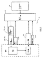
図1は、例示のみにより、本発明による神経近接度、神経の方向、および神経病理学評価を採用し得るシステム10を示す。以下により詳細に説明されるように、手術システム10は、外科手順の間に、任意の数の手術標的部位への安全かつ再現性ある接近を提供し得、および神経病理学における変化(健常または状況)をモニターし得る。本明細書では、多くは脊椎手術における使用に関して記載されるけれども、本発明の手術システム10および関連する方法は、重要な神経構造をもつ組織が、手術の通路を確立するために通過されるかまたは近傍を通過されなければならない、任意の多くのさらなる外科手順における使用に適切であることが明瞭に注記される。
FIG. 1 illustrates, by way of example only, a
この手術システム10は、コントロールユニット12、患者モジュール14、この患者モジュール14にカップルされたEMGハーネス16および戻り電極35、および1つ以上のアクセサリーケーブル22を経由して患者モジュール14にカップルされ得る手術アクセサリー20のホストを含む。この手術アクセサリー20は、かならずしも制限されるわけではないが、手術アクセス部材(K−ワイア24、1つ以上の拡張カニューレ26、および作動カニューレ28など)、神経病理学モニタリングデバイス(神経根開創器30など)、および梗節スクリュー試験を実施するためのデバイス(スクリュー試験プローブ32など)を含み得る。手術システム10のブロックダイアグラムが図2に示され、その動作は、以下の記載を考慮して容易に明らかである。
The
コントロールユニット12は、タッチスクリーンディスプレイ36およびベース38を含む。好ましくは、タッチスクリーンディスプレイ36は、ユーザーに情報を伝達し、かつユーザーからの指示を受け得るグラフィカルユーザーインターフェース(GUI)を備える。ベース38は、刺激供給源を指令し、患者モジュール14からのデジタル化信号およびその他の情報を受け、そしてEMG応答を処理して各筋肉群の特徴的情報を抽出し、そして処理されたデータをディスプレイ36を経由してオペレーターに表示するコンピューターハードウェアおよびソフトウェアを含む。コントロールユニット12内のソフトウェアの主要な機能は、タッチスクリーンディスプレイ36を経由してユーザー指令を受けること、要求されたモード(神経近接度、神経方向、神経病理学、スクリュー試験)で刺激を活性化すること、規定されたアルゴリズム(以下に記載する)に従って信号データを処理すること、受けたパラメーターおよび処理されたデータを表示すること、ならびにシステムステータスおよび報告欠陥状態をモニターすることを含む。
The
患者モジュール14は、シリアルケーブル40を経由してコントロールユニット12に接続され、そしてすべての電極への電気的接続、信号調整回路、刺激器ドライブおよび操縦回路、ならびにコントロールユニットへのデジタル通信インターフェースを含む。使用において、コントロールユニット12は、手術場の外側であるが近接して(手術テーブルに隣接するカート上など)位置され、ディスプレイ36は容易に見えるように外科医に向けられる。患者モジュール14は、患者の脚間に位置決めされるか、またはベッドレールクランプを用いて中脚レベルで手術テーブルの末端に固定され得る。この選択された位置は、EMG配線が、手術手順の間に引っ張りなくそれらの最遠の所望位置に到達し得るようであるべきである。
The
本発明の重要な局面は、ディスプレイ36上でユーザーに表示された情報が、必ずしも制限されるわけではなく、神経近接度、神経の方向、神経病理学、刺激レベル、筋節/EMGレベル、スクリュー試験、進行または保持指示、および器具使用に関する、英数字および/または画像情報を含み得る。1つの実施形態では(例示のみで提示する)、このディスプレイは、表1に提示される以下の要素を含む。
An important aspect of the present invention is that the information displayed to the user on the

手術接近部材24−28は、患者の皮膚と手術標的部位との間の組織を平滑に解剖するように設計されている。初期拡張カニューレ26は、好ましくは、任意の数の市販されている手術案内フレームを用いて整列された後、標的部位に向かって進められる。閉塞具(示さず)が、初期拡張器26内側に含められ得、そして同様に1つ以上の刺激電極を備え得る。一旦適正な位置が達成されると、閉塞具(示さず)が取り除かれ得、そしてK−ワイア24が初期拡張カニューレ26の中央に下に挿し下ろされ、そして椎間円板の環帯のような所定の標的部位にドッキングする。次いで、増加する直径のカニューレが、先に据え付けられたカニューレ26の上を、所望の管腔が据え付けられるまで案内される。例示のみにより、拡張カニューレ26は、6mm〜30mmの範囲の直径であり得る。1つの実施形態では、各カニューレ26は、先端に、4つの直交する刺激電極をもち、以下に記載されるように、検出および方向評価を可能にする。作動カニューレ28は、最後の拡張カニューレ26上に据え付けられ、そして次にすべての拡張カニューレ26が作動カニューレ28の内管腔の内側から取り除かれ、それを通る手術通路を確立する。刺激器駆動器42が提供され、特定の手術接近部材24−28を(アクセサリーケーブルを経由して)患者モジュール14に電気的に接続させる。好適な実施形態では、この刺激器駆動器42は、刺激電流を選択的に活性化し、および/またはそれを特定の手術接近部材に向けるための1つ以上のボタンを含む。
The surgical access member 24-28 is designed to smoothly dissect tissue between the patient's skin and the surgical target site. The
手術システム10は、特定の神経により刺激される筋肉群のEMG応答をモニターしながら、神経根開創器30の遠位端にある1つ以上の刺激電極を経由して開創された神経根を電気的に刺激することによって神経病理学モニタリングを達成する。このEMG応答は、電気刺激により引き起こされる神経脱分極の定量的尺度を提供する。次いでEMG応答の分析を用いて、以下により詳細に記載されるように、神経または神経構造の開創が神経機能に影響する程度を評価し得る。このようなモニタリングの1つの利点は、例示のみにより、神経の伝達が手順の間にモニターされ得、特定の手術手順の結果として、神経の神経生理学および/または機能が(より良くまたはより悪く)変化するか否かを決定する。例えば、神経伝達が手術の結果として増加することが観察され得、これは、先に阻害された神経が手術によりポジティブに影響されたことを示す。神経根開創器30は、神経または神経根との接触を維持し得る任意の数の適切なデバイスを備え得る。この神経根開創器30は、任意の数の異なる様式の寸法とされ得、これは、(開創される間に神経が位置決めされ得る凹上領域を示す図1の側面図に示されるような)ほぼ湾曲した遠位領域を有し得、そして手術の間所望の位置で開創された神経を維持するために十分な寸法(幅および/または長さ)および剛直性であり得る。この神経根開創器30はまた、神経根開創器30の端部に刺激電極(単数または複数)に電気刺激を選択的に印加するための1つ以上のボタンを有するハンドル31を備え得る。1つの実施形態では、神経根開創器30は使い捨て可能であり、そしてハンドル31は、再利用およびオートクレーブ可能である。
The
手術システム10はまた、スクリュー試験プローブ32の使用によりスクリュー試験評価を実施するために採用され得る。このスクリュー試験プローブ32を用いて梗節穴(形成後)および/またはスクリュー(導入後)の一体性を試験する。このスクリュー試験プローブ32は、ハンドル44およびほぼボール型の先端48を有するプローブ部材46を含む。ハンドル44は、プローブ部材46の端部にあるボール型先端の端部48に電気刺激を選択的に印加するための1つ以上のボタンを備え得る。このスクリュー試験プローブ32のボール型先端48は、スクリュー挿入前にスクリュー穴に配置されるか、または据え付けられたスクリューヘッド上に配置される。梗節壁がスクリューまたはタップにより破られると、刺激電流が隣接する神経根に通過し、そしてそれらは、より低い刺激電流で脱分極する。
The
スクリュー試験ハンドル44上のボタンを押すと、ソフトウェアはアルゴリズムを実行し、これによって、すべてのチャンネルタブが着色コード化され、対応する神経の検出状態を示す。「最も悪い」(最も低い)レベルであるチャンネルは、ハイライトされ(大きくなり)、しかも、筋節名が表示され、そして脊椎図上に画像で描かれる。垂直の棒のチャートもまた示され、選択されたチャンネルについて神経脱分極に必要な刺激電流をmAで描く。好ましくは、スクリュー試験アルゴリズムは、すべての8つのEMGチャンネルについて脱分極(閾値)電流を決定する。外科医はまた、スクリュー試験プローブ32で直接神経根を刺激することによりベースライン閾値電流をセットし得る。外科医は、このベースラインに対するスクリュー試験閾値電流を表示することを選択し得る。ハンドル44は、システムに対しそれが取り付けられるときそれ自身を識別するための(ハードウェアおよび/またはソフトウェアにより)機構を備え得る。1つの実施形態では、このプローブ部材は、使い捨て可能かつオートクレーブ可能である。
When a button on the screw test handle 44 is pressed, the software executes an algorithm whereby all channel tabs are color coded to indicate the corresponding nerve detection status. The channel that is the “worst” (lowest) level is highlighted (larger), and the sarcomere name is displayed and imaged on the vertebral diagram. A vertical bar chart is also shown, depicting the stimulation current required for neural depolarization in mA for the selected channel. Preferably, the screw test algorithm determines the depolarization (threshold) current for all eight EMG channels. The surgeon may also set the baseline threshold current by stimulating the nerve root directly with the
音声ピックアップ(示さず)もまた、本発明によるオプションの特徴として提供され得る。いくつかの場合では、神経が伸張されるか、または圧縮されるとき、自然の神経活性の破裂または列を発し得る。この音声ピックアップは、このような活性を表す音を、外科医が、神経に対するストレスがあるか否かを彼が決定することを支援する音声に関するこの応答をモニターし得るように伝達し得る。 An audio pickup (not shown) may also be provided as an optional feature according to the present invention. In some cases, when the nerve is stretched or compressed, it may rupture or resemble natural nerve activity. The voice pickup may transmit a sound representative of such activity so that the surgeon can monitor this response for the voice that helps him determine whether there is stress on the nerve.
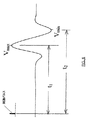
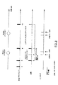
本発明によるEMG応答の分析をここで記載する。本発明の、神経近接度、神経の方向、および神経病理学は、上記手術システム10によりモニターされた種々の筋肉筋節の誘起された応答を評価することに基づく。これは、図3−4に最も良く示され、ここで、図3は、図4に示される刺激電流パルスに対してモニターされた筋節の誘起された応答(EMS)を示す。このEMG応答は、Vpp=Vmax−Vminであるピーク間電圧により特徴付けられ得る。好ましくは、この刺激電流はDC接続され、そしてソフトウェアにより調節されている周波数および振幅をもつ200ミリ秒の単相パルスで構成される。各神経および筋節について、刺激電流パルスからEMG応答まで特徴的な遅延がある。
The analysis of the EMG response according to the present invention will now be described. The nerve proximity, nerve orientation, and neuropathology of the present invention are based on evaluating the induced responses of the various muscle sarcomas monitored by the
図5に示されるように、主要神経幹を脱分極するために必要な閾値刺激電流がある。この閾値未満では、電流刺激は有意なVpp応答を誘起しない。一旦刺激閾値が達成されると、誘起された応答は再現可能であり、そして図5に示されるように、増加する刺激とともに増加する。これは、「回復曲線」として知られる。1つの実施形態では、有意なVppは、最小100μVであると規定される。この閾値電圧を誘起した最低の刺激電流は、Ithreshと呼ばれる。Ithreshは、刺激電極が神経に接近するにつれて減少する。この値は、外科医にとって有用である。なぜなら、それは、電極から神経への距離(近接度)の相対的指標を提供するからである。 As shown in FIG. 5, there is a threshold stimulation current required to depolarize the main nerve trunk. Below this threshold, current stimulation does not induce a significant V pp response. Once the stimulation threshold is achieved, the induced response is reproducible and increases with increasing stimulation, as shown in FIG. This is known as the “recovery curve”. In one embodiment, a significant V pp is defined to be a minimum of 100 μV. The lowest stimulation current that induced this threshold voltage is called I thresh . I thresh decreases as the stimulation electrode approaches the nerve. This value is useful for the surgeon. This is because it provides a relative indication of the distance (proximity) from the electrode to the nerve.
図6に示されるように、各神経/筋節組み合わせについて、刺激電流パルスからEMS応答までに特徴的な遅延が存在する。各刺激電流パルスについて、この電流パルスから最初の最大/分までの時間がT1であり、そして第2の最大/分までがT2である。パルスの最初の相はポジティブまたはネガティブである。以下に記載されるように、T1、T2の値は、各々、サンプリング速度と同じ広さの幅(bin)をもつヒストグラムにコンパイルされる。各刺激で新たな値のT1、T2が獲得され、ヒストグラムが連続的にアップデートされる。用いられるT1およびT2の値は、ヒストグラム中の最大の幅(bin)の中心値である。T1、T2の値は、ヒストグラムが変化するにつれ、連続的にアップデートされる。最初に、全EMG応答を含むウインドウを用いてVppが獲得される。20サンプルの後、T1、T2ウインドウの使用を、200サンプルの期間に亘って段階的に調整する。次いで、VmaxおよびVminを、例示のみによって、5msecの幅で、T1、T2を中心とするウインドウの間でのみ獲得する。Vppを獲得するこの方法は、(以下により詳細に記載されるように)それがアーチファクト拒絶を自動的に実施する点で有利である。 As shown in FIG. 6, there is a characteristic delay from the stimulation current pulse to the EMS response for each nerve / sarcomere combination. For each stimulation current pulse, the time from this current pulse to the first max / min is T 1 and to the second max / min is T 2 . The first phase of the pulse is positive or negative. As described below, the values of T 1 and T 2 are each compiled into a histogram having the same width as the sampling rate. With each stimulus, new values of T 1 and T 2 are acquired and the histogram is continuously updated. The T 1 and T 2 values used are the center values of the maximum width (bin) in the histogram. The values of T 1 and T 2 are continuously updated as the histogram changes. First, V pp is obtained using a window containing the entire EMG response. After 20 samples, the use of the T 1 , T 2 window is adjusted stepwise over a period of 200 samples. Then, V max and V min are obtained only by way of example, with a width of 5 msec and only between windows centered at T 1 and T 2 . The method of obtaining the V pp is advantageous in that automatically performs the (as described in more detail below) it artifact rejection.
以下により詳細に説明されるように、本発明による「回復曲線」の使用は、それから種々の評価(制限されないで、神経検出、神経の方向、および神経病理学モニタリングを含む)を作成する大量の有用データを提供する点で有利である。さらに、それは、伝統的なEMGシステムにおいてユーザーに表示される実際のEMG波形に対して、ユーザーに単純化されているが、なお意味のあるデータを提示する能力を提供する。EMG波形を解釈することにおける複雑さに起因して、代表的には、このような先行技術システムは、このような事項に特別に訓練されたさらなる人を必要とする。これは、次に、それは、(なお別の高度に訓練された人の随行を有する)過剰の出費に変形されるという不利益であり得、しばしば、スケジューリング問題を提示する。なぜなら、大部分の病院は、このような職員を保持していないからである。特定の個人が実際のEMG波形を観察することを欲するという可能性を説明するために、手術システム10は、リアルタイムにすべて8つのEMGチャンネルの電圧波形を示す誘起電位表示を含む。それは、電流刺激パルスに対する各モニターされた筋節の応答を示す。この表示は、刺激パルスが存在する各時間にアップデートされる。この誘起電位表示は、検出、方向、または神経病理学モニタリングの間にアクセスされ得る。
As will be explained in more detail below, the use of a “recovery curve” according to the present invention can then be used to generate a large number of evaluations, including but not limited to nerve detection, nerve orientation, and neuropathology monitoring. This is advantageous in providing useful data. Furthermore, it provides the user with the ability to present simplified but yet meaningful data to the actual EMG waveform displayed to the user in a traditional EMG system. Due to the complexity in interpreting EMG waveforms, typically such prior art systems require additional people specially trained in such matters. This can then be a disadvantage that it is transformed into excessive spending (with the attendance of yet another highly trained person), often presenting a scheduling problem. This is because most hospitals do not have such staff. To account for the possibility that a particular individual wants to observe the actual EMG waveform, the
(神経検出(近接度))
本発明の神経検出関数を用いて、刺激電極(すなわち、手術接近部材24−28上に見出される電極)で神経を検出し、そして手術標的部位に向かって進むにつれて電極に対する神経の近接度の相対的指標をユーザーに与える。本発明の1つの実施形態による神経近接度検出の方法は、以下のように要約される:(1)刺激電流パルスが、200μsの固定されたパルス幅および可変振幅で電極から発せられる;(2)関連する筋肉群のEMG応答が測定される;(3)EMG応答のVppが、T1、T2およびFmax(NB:T2前に決定され、定数FsafeがFmaxのために用いられる)を用いて決定される;(4)迅速探索検出アルゴリズムを用いて既知のVthresh最小値に対するIthreshを決定する;(5)Itの値を、神経の近接度の相対的指標としてユーザーに表示し、ここで、このIthreshが、プローブが神経により近接するときを低減すると期待される。先行するステップと関連するアルゴリズムの詳細な記載は、この近接度情報がユーザーに伝達される様式の一般的記載の後に続く。
(Neural detection (proximity))
Using neural detection function of the present invention, stimulation electrodes (i.e., surgical approach members 24-28 are electrodes found on) nerve detects at, And proximity of the nerve to the electrode as it travels toward the surgery target site Give users a relative measure of. The method of neural proximity detection according to one embodiment of the present invention is summarized as follows: (1) A stimulation current pulse is emitted from an electrode with a fixed pulse width and variable amplitude of 200 μs; (2 ) The EMG response of the relevant muscle group is measured; (3) V pp of the EMG response is determined before T 1 , T 2 and F max (NB: T 2 , and the constant F safe is for F max determining the I thresh to known V thresh minimum value using (4) rapid search detection algorithm; as determined using the using is) (5) the value of I t, the relative indicator of proximity of neural To the user, where this I thresh is expected to reduce when the probe is closer to the nerve. A detailed description of the algorithm associated with the preceding steps follows the general description of the manner in which this proximity information is communicated to the user.
検出関数は、外科医に、Ithreshの値をカラーコードとともに表示し、その結果、外科医は、神経組織との接触を避けるためにこの情報を用い得る。これは、ほぼ図7に示されており、これは、本発明による例示のスクリーン表示を示す。検出表示は、Vthresh(名目上100μV)より大きいEMG Vpp応答を誘起するために必要な電流(Ithresh)の振幅に基づく。1つの実施形態によれば、Ithreshが4mA以下である場合、赤が表示され、Ithreshの絶対値が表示される。4mA<Ithresh<10mAであれば黄が表示される。Ithreshが10mA以上であれば緑が表示される。通常、Ithreshは、それが赤の範囲であるときのみ表示される。しかし、外科医は、すべて3つの範囲(赤、黄、緑)についてIthreshを表示するオプションを有している。好ましくは、最大刺激電流は、ユーザーによりセットされ、そして好ましくは0〜100mAの間の範囲内である。検出は、選択された側面のすべての4つのチャンネル上で実施される。対向する側面上のEMGチャンネルは用いられない。第1の拡張器26は、刺激用の電極を有する閉塞器を用い得る。1つの実施形態では、すべての引き続く拡張器26および作動カニューレ28は、刺激のために4つの電極を用いる。4つの電極からのIthreshの最低値を表示のために用いる。外科医に、計算が終了し、そして彼が器具を進めることを継続し得るときを告げる「進行/保持」表示がある。
The detection function displays to the surgeon the value of I thresh with a color code so that the surgeon can use this information to avoid contact with neural tissue. This is generally illustrated in FIG. 7, which shows an exemplary screen display according to the present invention. The detection indication is based on the amplitude of the current (I thresh ) required to induce an EMG V pp response greater than V thresh (nominally 100 μV). According to one embodiment, if I thresh is 4 mA or less, red is displayed and the absolute value of I thresh is displayed. If 4 mA <I thresh <10 mA, yellow is displayed. If I thresh is 10 mA or more, green is displayed. Normally, I thresh is displayed only when it is in the red range. However, the surgeon has the option to display I thresh for all three ranges (red, yellow, green). Preferably the maximum stimulation current is set by the user and is preferably in the range between 0 and 100 mA. Detection is performed on all four channels of the selected side. The EMG channel on the opposite side is not used. The
閾値探索アルゴリズムは、一連の単極刺激を採用し、範囲にある各EMGチャンネルについて刺激電流閾値を決定する。神経は、Istimの振幅をもつ電流パルスを用いて刺激される。筋肉群は、Vppのピーク電圧を有する誘起電位で応答する。このアルゴリズムの目的は、迅速にIthreshを見出すことである。これは、既知の閾値電圧Vthreshより大きなVppを生じる最小Istimである。Istimの値は、以下のようなブラケッティング法により調節される。最初のブラケットは、0.2mAおよび0.3mAである。これら刺激電流の両方に対応するVppがVthreshより低い場合、そのときは、ブラケットサイズを2倍にして0.2mAおよび0.4mAにする。このブラケットサイズの指数的2倍化をブラケットの上端がVthreshを超えるVppを生じるまで継続する。次いで、ブラケットサイズを両断法により減少する。ブラケットの中央点にある電流刺激値を用い、そしてこれが、Vthreshを超えるVppを生じる場合、そのときは、下半分が新たなブラケットになる。同様に、中央点VppがVthresh未満である場合、そのときは、上半分が新たなブラケットになる。この両断法を、ブラケットサイズがI thresh mAまで減少するまで用いる。Ithreshは、ブラケットのより高い端にあるIstimの値である。 The threshold search algorithm employs a series of monopolar stimuli and determines a stimulation current threshold for each EMG channel in range. The nerve is stimulated with a current pulse having an amplitude of I stim . Muscle groups, it responds with induced potential having a peak voltage of V pp. The purpose of this algorithm is to find I thresh quickly. This is the minimum I stim that produces a V pp greater than the known threshold voltage V thresh . The value of I stim is adjusted by the following bracketing method. The first bracket is 0.2 mA and 0.3 mA. If V pp corresponding to both of these stimulation currents is lower than V thresh , then double the bracket size to 0.2 mA and 0.4 mA. This exponential doubling of the bracket size continues until a V pp is produced where the upper end of the bracket exceeds V thresh . The bracket size is then reduced by a double cut method. If the current stimulus value at the center point of the bracket is used and this results in a V pp that exceeds V thresh , then the lower half becomes the new bracket. Similarly, if the center point V pp is less than V thresh , then the upper half becomes a new bracket. This bisection method is used until the bracket size is reduced to I thresh mA. I thresh is the value of I stim at the higher end of the bracket.
より詳細には、図8(A)〜図8(E)を参照して、閾値探索は、3つの状態:ブラケッティング、両断、およびモニタリングを指示する。刺激電流ブラケットは、刺激電流閾値Ithreshを囲む刺激電流の範囲である。ブラケットの上および/または下境界は不確定であり得る。ブラケットの幅は、上境界値マイナス下境界値である。チャンネルの刺激電流閾値Ithreshが、最大刺激電流を超える場合、その閾値は範囲外であると考えられる。ブラケッティング状態の間、閾値探索は、以下の方法を採用し、刺激電流を選択し、そして範囲にある各EMGチャンネルについて刺激電流ブラケットを同定する。 More specifically, with reference to FIGS. 8A-8E, the threshold search indicates three states: bracketing, double break, and monitoring. The stimulation current bracket is a range of stimulation currents that surrounds a stimulation current threshold I thresh . The upper and / or lower boundary of the bracket can be indeterminate. The width of the bracket is the upper boundary value minus the lower boundary value. If the channel stimulation current threshold I thresh exceeds the maximum stimulation current, the threshold is considered out of range. During the bracketing state, the threshold search employs the following method to select a stimulation current and identify a stimulation current bracket for each EMG channel in range.
最小刺激電流を見出すための方法は、ブラケッティングおよび両断の方法を用いる。「根(root)」は、適切な応答を誘起しない刺激電流について値−1;応答を誘起する刺激電流について値+1を有する関数について同定される。根は、この関数が、刺激電流が増加するにつれて、−1から+1にジャンプするとき生じ;この関数は、正確にゼロの値を決して有さない。この根は、正確には知られず、あるレベルの正確さをもつのみである。この範囲の上境界は、最低刺激電流IThreshであり、ここで、この関数は、値+1、すなわち、V Thresh 応答を誘起する最小の刺激電流に戻る。 As a method for finding the minimum stimulation current, a method of bracketing and bisection is used. A “root” is identified for a function having a value −1 for a stimulation current that does not elicit an appropriate response; a value +1 for a stimulation current that elicits a response. The root occurs when this function jumps from -1 to +1 as the stimulation current increases; this function never has a value of exactly zero. This root is not exactly known and has only a certain level of accuracy. The upper boundary of this range is the lowest stimulation current I Threshold , where the function returns to the value +1, ie, the minimum stimulation current that elicits a V Threshold response.
近接度関数は、刺激電流を、上記根が取り囲まれるまで調節することにより始まる(図8(B))。最初のブラケッティング範囲は、任意の数の適切な範囲で提供され得る。1つの実施形態では、この最初のブラケッティング範囲は、0.2〜0.3mAである。上刺激電流が応答を誘起しない場合、この範囲の上端は増加されるべきである。範囲スケール因子は2である。この刺激電流は、決して、1つの反復において10mAより大きく増加されるべきではない。この刺激電流は、プログラムされた最大刺激電流を決して超えるべきではない。各刺激について、アルゴリズムは、各活性チャンネルの応答を調べ、それがそのブラケット内に入るか否かを決定する。一旦各チャンネルの刺激電流閾値が、囲まれたならば、このアルゴリズムは両断状態に遷移する。 The proximity function begins by adjusting the stimulation current until the root is surrounded (FIG. 8B). The initial bracketing range can be provided in any number of suitable ranges. In one embodiment, this initial bracketing range is 0.2-0.3 mA. If the top stimulation current does not induce a response, the upper end of this range should be increased. The range scale factor is 2. This stimulation current should never be increased more than 10 mA in one iteration. This stimulation current should never exceed the programmed maximum stimulation current. For each stimulus, the algorithm examines the response of each active channel and determines whether it falls within that bracket. Once the stimulation current threshold for each channel is enclosed, the algorithm transitions to a bi-state.
両断状態の間(図8(C)および8(D))、閾値探索は、以下に記載の方法を採用し、刺激電流を選択し、そして範囲内閾値をもつ各EMGチャンネルについて0.1mAの幅にブラケットを狭める。最小の刺激電流が囲まれた後(図8(B))、根を含む範囲が、根が特定された正確さで知られるまで洗練される。両断法を用いて根を含む範囲を洗練する。1つの実施形態では、根は、0.1mAの正確さまで見出されるべきである。両断法の間、ブラケットの中央点にある刺激電流が用いられる。刺激が応答を誘起する場合、ブラケットを先の範囲の下半分に縮める。刺激が応答を誘起しない場合、ブラケットを先の範囲の上半分に縮める。近接度アルゴリズムは、応答閾値が0.1mA分離された刺激電流によって囲まれるとき、電極位置上でロックされる。このプロセスは、各々の活性チャンネルについて、すべての閾値が正確に知られるまで繰り返される。その時点で、このアルゴリズムはモニタリング状態に入る。 During both breaks (FIGS. 8 (C) and 8 (D)), the threshold search employs the method described below, selects the stimulation current, and 0.1 mA for each EMG channel with an in-range threshold. Narrow the bracket to the width. After the minimum stimulation current is enclosed (FIG. 8B), the range containing the root is refined until the root is known with the specified accuracy. Refine the range including the roots using the double-cut method. In one embodiment, the roots should be found to an accuracy of 0.1 mA. During both cuts, the stimulation current at the center point of the bracket is used. If the stimulus elicits a response, the bracket is retracted to the lower half of the previous range. If the stimulus does not elicit a response, the bracket is retracted to the upper half of the previous range. The proximity algorithm is locked on the electrode position when the response threshold is surrounded by 0.1 mA separated stimulation current. This process is repeated for each active channel until all thresholds are known accurately. At that point, the algorithm enters a monitoring state.
モニタリング状態の間(図8(E))、閾値探索は、以下に記載の方法を採用して刺激電流を選択し、そして刺激電流閾値が変化しているか否かを同定する。このモニタリング状態では、刺激電流レベルは、特定のチャンネルの応答に依存して、0.1mAだけ減少または増加する。閾値が変化しない場合、そのときは、ブラケットの下端は、応答を誘起するべきではなく、その一方、ブラケットの上端はすべきである。これらの状態のいずれかが起きない場合、従ってブラケットは調節される。このプロセスは、活性チャンネルの各々について繰り返され、各閾値が囲まれることを確実にするために継続される。刺激が、列において3回予期される応答を誘起しない場合、そのときは、このアルゴリズムは、ブラケットを再確立するためにブラケッティング状態に遷移させて戻す。 During the monitoring state (FIG. 8 (E)), the threshold search employs the method described below to select the stimulation current and identify whether the stimulation current threshold is changing. In this monitoring state, the stimulation current level is reduced or increased by 0.1 mA depending on the response of the particular channel. If the threshold does not change, then the lower end of the bracket should not induce a response, while the upper end of the bracket should. If any of these conditions does not occur, the bracket is adjusted accordingly. This process is repeated for each of the active channels and continued to ensure that each threshold is enclosed. If the stimulus does not elicit the expected response three times in the queue, then the algorithm transitions back to the bracketing state to re-establish the bracket.
1つ以上のチャンネルについて刺激電流閾値(It)を決定することが必要であるとき、それらは、図9に示されるような閾値探索アルゴリズムを時間複合することにより得られる。ブラケッティング状態の間、アルゴリズムは、0.2mAの刺激電流ブラケットで開始し、そしてブラケットのサイズを指数的に増加する。各ブラケットで、アルゴリズムはすべてのチャンネルのVppを測定し、それらがどのブラケットに入るかを決定する。この第1の通過の後、アルゴリズムは、どの指数ブラケットが、各チャンネルのItを含むかを知る。次に、両断状態の間、アルゴリズムは、Itを含む最も低い指数ブラケットで開始して、それを、Itが0.1mA内に見出されるまで両断する。指数ブラケット内に1つ以上のItが存在する場合、それらは、両断プロセスの間に分離され、そして最低値をもつItが最初に見出される。モニタリング状態の間、アルゴリズムは、最低値から開始して、各Itについてブラケットの上境界および下境界をモニターする。1つ以上のチャンネルについてItがそのブラケット内に見出されない場合、そのときは、アルゴリズムは、これらチャンネルのブラケットを再確立するためブラケッティング状態に戻る。 When it is necessary to determine the stimulation current threshold (I t ) for one or more channels, they are obtained by time complexing a threshold search algorithm as shown in FIG. During the bracketing state, the algorithm starts with a 0.2 mA stimulation current bracket and increases the bracket size exponentially. At each bracket, the algorithm measures V pp for all channels and determines which bracket they are in. After this first pass, the algorithm, which index bracket, know including I t of each channel. Then, during the bisected state, the algorithm, starting with the lowest index bracket including I t, it is bisected until I t is found in the 0.1 mA. If there are one or more I t in the exponential bracket, they can be separated during the bisection process, and I t with the lowest value is found first. During the monitoring state, the algorithm, starting from the lowest value, to monitor the upper boundary and the lower boundary of the brackets for each I t. If for one or more channels I t is not found within the bracket, then the algorithm returns to the bracketing state to reestablish these channels brackets.
ここで、本発明による自動的アーチファクト拒絶を実施する方法を記載する。上記のように、本発明に従って(図6に示されるT1、T2に基づき)Vppを獲得することは、とりわけ、それが、アーチファクト拒絶を自動的に実施するという点にある。神経は、刺激閾値を超える一連の電流パルスを用いて刺激される。筋肉群は、ピーク間電圧Vppをもつ誘起された電位で応答する。各EMG応答パルスについて、T1は、刺激パルスから最初の極大値(VmaxまたはVmin)まで測定された時間であり、T2は、電流パルスから第2の極大値(VmaxまたはVmin)まで測定された時間である。T1およびT2の値は各々、Tbinmsecのビン(bin)幅でヒストグラムにコンパイルされる。アーチファクト拒絶に用いられるT1およびT2の値は、ヒストグラムにおける最大ビンの中心値である。EMG応答を獲得するときにアーチファクトを拒絶するため、VmaxおよびVminは、T1±Twin、およびT2±Twinであるウインドウの間でのみ獲得される。ここで再び図6を参照して、Vppは、Vmax−Vminである。 A method for implementing automatic artifact rejection according to the present invention will now be described. As noted above, obtaining V pp according to the present invention (based on T1, T2 shown in FIG. 6) is, among other things, that it automatically performs artifact rejection. The nerve is stimulated with a series of current pulses that exceed the stimulation threshold. The muscle group responds with an induced potential with a peak-to-peak voltage V pp . For each EMG response pulse, T 1 is the time measured from the stimulation pulse to the first maximum (V max or V min ), and T 2 is the second maximum (V max or V min from the current pulse). ) Is the time measured until. The values of T 1 and T 2 are each compiled into a histogram with a bin width of T bin msec. The T 1 and T 2 values used for artifact rejection are the center values of the largest bins in the histogram. In order to reject artifacts when acquiring EMG responses, V max and V min are acquired only between windows that are T 1 ± T win and T 2 ± T win . Here, referring again to FIG. 6, V pp is V max −V min .
自動的アーチファクト拒絶の方法は、さらに、図10を参照して説明される。閾値探索アルゴリズムが活性である間、各刺激の後、範囲にある各EMGセンサーチャンネルについて以下のステップが実施される:(1)(刺激アーチファクト拒絶後)波形最大および最小の時間サンプル値をヒストグラムに配置する;(2)ヒストグラムビンサイズをサンプリング期間と同じ粒度にする;(3)ヒストグラムを、閾値探索アルゴリズムが活性化される時毎に空にする;(4)ヒストグラムが2つのピーク、または最大カウントをもつ2つのビンとして規定されるモードを提供する;(5)最初のモードをT1と規定し;第2のモードをT2と規定する;(6)(おそらくは不連続な)範囲の波形サンプルを同定する;(7)閾値探索アルゴリズムが活性化された後の最初の刺激について、サンプルの範囲が全波形になる;(8)特定された数の刺激の後に、サンプルの範囲がT1±0.5msおよびT2±0.5msになる;および(9)特定された数の刺激の前に、いずかの範囲を用い、この制限を受ける;全波形を用いる刺激の比率が100%から0%まで減少する(この比率を支配する曲線のサンプルが図11に示される)。ピーク間電圧(Vpp)が、波形サンプルの同定された範囲に亘っていずれかで測定される。好ましくは、特定された数の刺激が220と240との間に存在する。 The method of automatic artifact rejection is further described with reference to FIG. While the threshold search algorithm is active, after each stimulus, the following steps are performed for each EMG sensor channel in range: (1) (After stimulus artifact rejection) Waveform maximum and minimum time sample values in a histogram (2) Make the histogram bin size the same granularity as the sampling period; (3) Empty the histogram every time the threshold search algorithm is activated; (4) The histogram has two peaks or max Provide a mode defined as two bins with counts; (5) define the first mode as T 1 ; define the second mode as T 2 ; (6) range (possibly discontinuous) Identify waveform samples; (7) For the first stimulus after the threshold search algorithm is activated, the sample range is full waveform. ; (8) after a specified number of stimulation, the range of the sample is T 1 ± 0.5 ms and T 2 ± 0.5 ms; and (9) in front of a specific number of stimuli, Izuka Subject to this limitation; the rate of stimulation using the full waveform is reduced from 100% to 0% (a sample of the curve governing this rate is shown in FIG. 11). The peak-to-peak voltage (V pp ) is measured anywhere over the identified range of waveform samples. Preferably, the specified number of stimuli is between 220 and 240.
本発明の別の局面によれば、刺激パルスの最大周波数が、図12を参照して自動的に得られる。各刺激の後、Fmaxが:Fmax=I/(T2+安全マージン)として、活性EMGチャンネルの各々からの最大T2について計算される。1つの実施形態では、この安全マージンは5msであるが、これは、任意の数の適切な持続期間に従って変動し得ることが企図される。特定された数の刺激の前に、刺激が、ブラケッティング状態の間に100〜120msの間隔、両断状態の間に200〜240msの間隔、およびモニタリング状態の間に400〜480msの間隔で実施される。特定数の刺激の後、ブラケッティング状態の間により早い間隔実行で(しかしFmaxよりは早くない)、両断状態の間により早い間隔実行で(しかしFmax/2よりは早くない)、そしてモニタリング状態の間により早い間隔実行で(しかしFmax/4よりは早くない)実施される。Fmaxが計算されるまで用いられる最大周波数は、好ましくは10Hzであるが、より遅い刺激周波数が、いくつかの獲得アルゴリズムの間に用いられ得る。用いられるFmaxの値は、周期的にアップデートされ、それがなお適切であることを確実にする。この特徴は、例示のみにより、図12中にグラフにより表される。生理学的理由のため、刺激の最大周波数は、患者あたりを基礎にセットされる。読み取り値がすべての筋節から取られ、そして最も遅い周波数(最高のT2)の読み取り値が記録される。 According to another aspect of the present invention, the maximum frequency of the stimulation pulse is automatically obtained with reference to FIG. After each stimulation, F max is calculated for the maximum T 2 from each of the active EMG channels as: F max = I / (T 2 + safety margin). In one embodiment, this safety margin is 5 ms, but it is contemplated that this may vary according to any number of suitable durations. Prior to the specified number of stimuli, the stimuli are performed at intervals of 100-120 ms during the bracketing state, at intervals of 200-240 ms during the bifurcation state, and at intervals of 400-480 ms during the monitoring state. The After a certain number of stimuli, at an earlier interval run during the bracketing state (but not earlier than F max ), at an earlier interval run between both break states (but not earlier than F max / 2) and monitoring Performed at a faster interval execution during the state (but not earlier than F max / 4). The maximum frequency used until F max is calculated is preferably 10 Hz, although slower stimulation frequencies can be used during some acquisition algorithms. The value of F max used is periodically updated to ensure that it is still appropriate. This feature is represented graphically in FIG. 12 by way of example only. For physiological reasons, the maximum frequency of stimulation is set on a per patient basis. Readings are taken from all sarcomas and the reading at the slowest frequency (highest T 2 ) is recorded.
(神経の方向)
作動カニューレ28または拡張カニューレ26を用いて一旦神経が検出されると、外科医は、方向関数を用い、接近部材24〜28上の参照マークに対して神経への角度方向を決定し得る。これはまた、図7に、神経の方向を示す矢印Aとして示される。この情報は、外科医が、彼または彼女がカニューレを進めるとき神経を避けることを補助する。カニューレから選択された神経への方向は、拡張カニューレ26および作動カニューレ28の先端上の直交する4つの電極を用いて推定される。好ましくは、これらの電極は、単極形態で操作される(すなわち、4つの電極の各々を刺激源として用いる)。神経の閾値電流(Ithresh)は、筋肉誘起電位応答Vppを測定すること、およびそれを既知の閾値Vthreshと比較することにより見出される。このアルゴリズムを用いて刺激電極から神経への方向を決定する。
(Neural direction)
Once the nerve is detected using the
図13に示されるように、この4つの電極は、原点から半径Rで二次元座標系のxおよびy軸上に配置されている。IThreshに等しい長さをもつ各電極に対応する軸に沿って、その電極に対するベクトルが原点から引かれる。原点から神経に向かって指す方向までのベクトルが、次いで計算される。このアルゴリズムは、図6を参照して上記で論議されたT1/T2アルゴリズムを採用する。図13に示される測定を用い、神経の(x、y)座標を、単一の点として取り、4つの電極の各々に対する神経からの距離の関数として決定され得る。これは、以下のように数学的に明確であり得る:
「円」が原点またはカニューレの中心に対する各電極の位置を示し、そして「六角形」が神経の位置を示し、そしてd1、d2、d3、およびd4が神経と電極1〜4との間の距離をそれぞれ示し、それは以下で示され得る:
x=d1 2−d3 2/−4Rおよびy=d2 2−d4 2/−4R
ここで、Rは、1に標準化されるカニューレ半径である。なぜなら、角度、および絶対値でない値が測定されるからである。
As shown in FIG. 13, these four electrodes are arranged on the x and y axes of the two-dimensional coordinate system with a radius R from the origin. A vector for that electrode is subtracted from the origin along the axis corresponding to each electrode having a length equal to I Thresh . A vector from the origin to the direction pointing towards the nerve is then calculated. This algorithm employs the T 1 / T 2 algorithm discussed above with reference to FIG. Using the measurements shown in FIG. 13 , the (x, y) coordinates of the nerve can be taken as a single point and determined as a function of the distance from the nerve for each of the four electrodes. This can be mathematically clear as follows:
“Circle” indicates the position of each electrode relative to the origin or the center of the cannula, “Hexagon” indicates the position of the nerve, and d 1 , d 2 , d 3 , and d 4 are the nerve and electrodes 1-4 Respectively, which can be shown below:
x = d 1 2 -d 3 2 / -4R and y = d 2 2 -d 4 2 / -4R
Where R is the cannula radius normalized to 1. This is because angles and values that are not absolute values are measured.
(x、y)から極座標(r、θ)への変換の後、次いでθは神経への角方向である。この角方向は、次いで、例示のみにより、図7に示されるように、神経の方を指す矢印Aとしてユーザーに表示される。この様に、外科医は、能動的に神経を避け得、それによって手術標的部位に接近する間に患者の安全性を増加する。外科医は、方向関数を実施するために利用可能な4つのチャンネルの任意の1つを選択し得る。好ましくは、外科医は、方向関数を用いている間、器具を移動または回転すべきではなく、むしろ器具を進めるために検出関数に戻るべきである。 After conversion from (x, y) to polar coordinates (r, θ), then θ is the angular direction to the nerve. This angular direction is then displayed to the user as an arrow A pointing towards the nerve, as shown in FIG. 7, by way of example only. In this way, the surgeon can actively avoid nerves, thereby increasing patient safety while approaching the surgical target site. The surgeon may select any one of the four channels available to perform the directional function. Preferably, the surgeon should not move or rotate the instrument while using the directional function, but rather should return to the detection function to advance the instrument.
接近器具24〜28の挿入および進行は、手術システム10が先端の経路中に存在し得る神経の存在のリアルタイム指標を提供することを可能にするに十分遅い速度で実施されるべきである。これを容易にするために、閾値電流IThreshは、計算が終了しそしてデータが正確であるときをそれが示すように表示され得る。例えば、検出情報がアップデートされ、そして器具は、今や外科医により進められる状態にあるとき、外科医にこの事実を通信するために飽和として現れるカラー表示を有することが企図される。器具の進行の間、チャンネルのカラー範囲が緑から黄に変化する場合、進行は、検出レベルの注意深い観察とともに、よりゆっくり進めるべきである。さらなる進行の後、チャンネルカラーが黄に留まるか、または緑に変わる場合、先端が通過し、神経から遠く離れて移動している可能性の指示である。しかし、さらなる進行の後、チャンネルカラーが赤に変わる場合、そのときは、器具先端が神経により近く移動した可能性の指示である。この点で、表示は、刺激電流閾値の値をmAで示す。さらなる進行は、閾値の値を観察しながら、そして臨床医がそれを安全とみなした場合のみ、極度の注意とともに試みられるべきである。臨床医が、器具先端をさらに進めることを決定した場合、閾値の値における増加(例えば、3mAから4mA)は、器具先端が神経を安全に通過したことを示し得る。それはまた、器具先端が神経に遭遇し、そしてそれを圧縮している指示であり得る。後者は、フリーで稼動する(上記のような)EMG音声出力上の神経活性の散発的な爆発、または「ポンという音(pop)」を聞くことにより検出され得る。器具のさらなる進行に際し、警告レベルが減少する(例えば、4mAから3mAまで)場合、そのときは、器具先端が脊椎神経に極度に近い可能性が非常に高く、そして神経損傷を避けるために、器具のさらなる操作の間、極度の注意を働かせるべきである。そのような状況下では、引き抜き、再配置、またはそうでなければ器具を操縦することの決定は、利用可能な情報および経験に基づく臨床医の唯一の思慮である。さらなるX線造影もまた、動作の最良の経路を確立するために適切と見なされ得る。
The insertion and progression of the access devices 24-28 should be performed at a rate that is slow enough to allow the
(神経病理学)
上記のように、手術システム10は、特定の神経により刺激される筋肉群のEMG応答をモニターする間、神経根開創器30の遠位端にある1つ以上の刺激電極を経由して開創された神経根を電気的に刺激することにより神経病理学モニタリングを確立する。図14は、健常である神経(A)と病的または非健常である神経(B)との間の差異を示す。本発明者らは、実験を通じて、神経病理学(または「健康」または「状態」)に関する情報が、本発明に従って生成された回復曲線から抽出され得ること(例えば、図3〜5に関する論議を参照のこと)を見出した。特に、健康な神経または神経束は、一般に、(図14中の回復曲線「A」上に示されるような)(y軸またはVpp値、およびx軸またはIStim値の両方に関して)低い閾値または「懸垂点」、相対的に鋭い傾き、および相対的に高い飽和領域を有する回復曲線を生成し得ることを見出した。それに対し、非健常であるか、またはそうでなければ(脊椎構造によって衝突されているか、または長期の収縮によるような)その機能が損なわれているか、または損傷している神経または神経束は、一般に、(図14中の回復曲線「B」上に示されるような)(再び、y軸またはVpp値、およびx軸またはIStim値の両方に関して)より高い閾値、減少した傾き、および相対的に低い飽和領域を有する回復曲線を生成する。これらの特徴を認識することにより、手順の間に収縮している神経根をモニターし得、その病理学または健康がそのような収縮により影響されている(すなわち、ネガティブに)か否かを決定する。さらに、手順前に(骨構造または膨張する環帯によって衝突されることにより引き起こされ得るような)病的または非健常と既に見なされる神経根をモニターし得、その病的または健康が手順により影響(すなわちポジティブに)されるか否かを決定する。
(Neuropathology)
As described above, the
手術システム10および関連する方法は、本発明の1つの実施形態に従って、上記に記載されている。本発明の範囲から逸脱することなく、種々の改変が行われ得るか、または特定のステップまたはアルゴリズムが省略されるかもしくは置換され得ることは容易に認識される。例示のみにより、特定の、これら代替実施形態または方法が以下に記載される。
The
(a.直線回帰による懸垂点検出)
所定の(上記に記載され、そして図5に示されるような)VThreshに基づいて刺激電流閾値(IThresh)を同定することに対し、直線回帰を経由してIThreshを決定することもまた本発明の範囲内である。これは、例示のみによって、同時に所有され、そして同時係属中の、「相対的神経移動および状況検出システムおよび方法」と題する2001年6月8日に出願された米国特許出願番号第09/877,713号に記載される直線回帰技法によって達成され得、その全体の内容は、本開示にあたかもその全体が提示されるように、参考として本明細書中に明瞭に援用される。
(A. Hanging point detection by linear regression)
In contrast to identifying a stimulation current threshold (I Thresh ) based on a given V Thresh (as described above and shown in FIG. 5), determining I Thresh via linear regression is also It is within the scope of the present invention. No. 09/877, filed Jun. 8, 2001 , entitled “Relative Nerve Migration and Situation Detection System and Method,” co-owned and co-pending, by way of example only. 713, the entire contents of which are expressly incorporated herein by reference as if fully set forth in this disclosure.
(b.動的掃引減算による懸垂点検出)
図15を参照して、懸垂点または閾値はまた、以下の動的掃引減算方法によって決定され得る。神経は、(上記のように)IMinからIMaxまで増加する電流パルスを用いるステップ80で刺激される。関連する筋群について得られる神経筋応答(誘起EMG)は、ステップ82で獲得される。次いで、ピーク間電圧(Vpp)が、ステップ84において、各電流パルスについて、図3〜6を参照して上記に記載のT1、T2アルゴリズムに従って抽出される。次に、最初の回復曲線(S1)が、ステップ86において、Vpp対IStimをプロットすることにより生成される。次いで、同じ神経が、ステップ88において刺激され、その結果、ピーク間電圧(Vpp)が、ステップ84で採用されるT1、T2フィルターなくして各EMG応答のVMaxからVMinを減算することにより抽出され得る。次いで、ステップ90において、Vpp対IStimをプロットすることにより、第2の回復曲線(S2)が生成される。両方の回復曲線S1、S2の生成は、最大刺激電流(IMax)に到達するまで続く(決定ステップ92による)。IMaxに到達しない場合、刺激電流IStimがステップ94で増分される。IMaxに到達する場合、そのときは、ステップ96において、第1の回復曲線S1が、第2の回復曲線S2から減算され、ステップ98に示される曲線「C」を生成する。S1をS2から減算することにより、得られる曲線「C」は、実際に、その特定の神経についての回復曲線の開始点(すなわち、閾値に到達する前の部分)である。このようにして、この曲線「C」中の最後の点は、IStimの最大値をもつ点であり、そしてそれ故、懸垂点である。
(B. Hanging point detection by dynamic sweep subtraction)
Referring to FIG. 15, the suspension point or threshold may also be determined by the following dynamic sweep subtraction method. The nerve is stimulated at
(c.末梢神経病理学モニタリング)
上記の神経病理学モニタリングスキームと同様に、本発明はまた、手順の経過の間に、存在すれば、末梢神経における変化をモニターする目的のために、(制限されずに、上記の接近部材24−28を含む)器具の部分(単数または複数)に沿って配置された1つ以上の電極の使用を企図する。特に、これは、使用において、1つ以上の刺激電極を、器具の遠位端から、それらが末梢神経と接触するようになるような可能性のある特定の距離に配置することにより達成され得る。例えば、手順の間に、シャフト中央の刺激電極を用いて末梢神経を刺激し得る。任意のこのような構成において、所定の末梢神経について回復曲線が生成され得、その結果、それは、神経根開創器に関して上記に記載したのと同じ様式で評価され得、器具と神経との間の接触が病理学後退を引き起こしているか否か、または手順自身が補助し、末梢神経の健康または状況を回復または改善するか否かを告げ得るという同じ利点を提供する。
(C. Peripheral neuropathology monitoring)
Similar to the neuropathology monitoring scheme described above, the present invention also provides (without limitation, the
(d.誘起電位刺激に対する実際の患者)
図16を参照して、本発明はまた、天然に存在する回復曲線を刺激するための「実際患者」デバイスの使用を企図する。これは、それが、動物および/またはヒト被験体なくしては試験し得ないであろう、本明細書に開示される種々のシステムを試験する能力を提供するという点で利益がある。実験室および/または手術時間を得る代表的な高コスト(人の資本および間接経費の両方に関する)に基づき、回復曲線を得るための実際の試験の必要性を排除することは顕著な奉献である。本発明によれば、これは、図16に示される信号を生成し得る適切なソフトウェアおよび/またはハードウェアを有するデバイス(示さず)を提供することにより達成され得る。好ましくは、このデバイスは、本発明による掃引電流信号(すなわち、0−100mAの振幅で掃引する200ミリ秒幅パルス)を受け、そしてこの電流入力パルスの振幅で変化するピーク間電圧(Vpp)を有する電圧パルスを生成する。出力Vppと入力刺激電流との関係は、示されたのと同様の回復曲線を生成する。1つの実施形態では、このデバイスは、回復曲線の特徴が選択的に改変され得るような種々の調節を含む。例えば、改変され得る特徴は、制限されずに、開始におけるVpp、開始の最大刺激電流(懸垂点)、直線領域の傾きおえび/または飽和領域のVppを含み得る。
(D. Actual patient for evoked potential stimulation)
Referring to FIG. 16, the present invention also contemplates the use of a “real patient” device to stimulate a naturally occurring recovery curve. This is beneficial in that it provides the ability to test the various systems disclosed herein that would not be possible without animal and / or human subjects. Based on the typical high cost of obtaining laboratory and / or surgery time (in terms of both human capital and overhead costs), eliminating the need for actual testing to obtain a recovery curve is a significant dedication . In accordance with the present invention, this can be accomplished by providing a device (not shown) with appropriate software and / or hardware that can generate the signals shown in FIG. Preferably, the device receives a swept current signal according to the present invention (ie, a 200 millisecond wide pulse sweeping with an amplitude of 0-100 mA) and a peak-to-peak voltage (V pp ) that varies with the amplitude of this current input pulse. A voltage pulse having The relationship between the output Vpp and the input stimulation current produces a recovery curve similar to that shown. In one embodiment, the device includes various adjustments such that the characteristics of the recovery curve can be selectively altered. For example, features that can be modified can include, but are not limited to, V pp at the start, maximum stimulation current (suspension point) at the start, slope of the linear region and / or V pp of the saturation region.
本発明を、本発明の目的を達成するための最良モードに関して記載しているが、本発明の思想または範囲から偏移することなく、これらの教示を考慮して種々の改変が達成され得ることが当業者により認識される。例えば、本発明は、コンピュータープログラミングソフトウェア、ファームウェアまたはハードウェアの任意の組み合わせを用いて履行され得る。本発明を実施すること、または本発明に従って装置を構成することに対する準備ステップとして、本発明によるコンピュータープログラミングコード(ソフトウェアまたはファームウェアにかかわらない)が、代表的には、固定(ハード)ドライバー、ディスケット、光ディスク、磁気テープ、(ROM、PROMなどのような)半導体メモリーのような1つ以上の機械読み出し可能な記憶媒体中に記憶され、それによって本発明による製造物品を作製する。コンピュータープログラミングコードを含む製造物品は、記憶デバイスから直接コードを実行することによるか、記憶デバイスから(ハードディスク、RAMなどのような)別の記憶デバイス中のこのコードをコピーすることによるか、または遠隔実行のためにネットワーク上にこのコードを伝達することのいずれかにより用いられる。当業者によって考察され得るように、上記の多くの異なる組み合わせが使用され得、そしてそれ故、本発明は添付の請求項の範囲によって制限されるものではない。 Although the present invention has been described with reference to the best mode for achieving the objects of the invention, various modifications can be accomplished in light of these teachings without departing from the spirit or scope of the invention. Will be recognized by those skilled in the art. For example, the present invention may be implemented using any combination of computer programming software, firmware or hardware. As a preparatory step for implementing the present invention or configuring the apparatus according to the present invention, the computer programming code according to the present invention (whether software or firmware) is typically a fixed (hard) driver, diskette, It is stored in one or more machine-readable storage media, such as optical disks, magnetic tapes, semiconductor memories (such as ROM, PROM, etc.), thereby producing a manufactured article according to the present invention. An article of manufacture containing computer programming code can be executed by executing code directly from a storage device, by copying this code from another storage device (such as a hard disk, RAM, etc.) from the storage device, or remotely Used by either passing this code over the network for execution. Many different combinations of the above may be used, as can be considered by one skilled in the art, and therefore the invention is not limited by the scope of the appended claims.
Claims (65)
筋肉上および筋肉内のうちの少なくとも一方に配置可能な少なくとも1つのEMG電極であって、該神経応答を検出する少なくとも1つのEMG電極と、At least one EMG electrode that can be placed on and / or in the muscle, the at least one EMG electrode detecting the neural response;
該コントロールユニットに電気的に結合され、該刺激信号を伝達する少なくとも1つの刺激電極を有する手術器具とA surgical instrument electrically coupled to the control unit and having at least one stimulation electrode for transmitting the stimulation signal;
を備え、With
該コントロールユニットは、該識別された刺激閾値に基づいて、該手術器具に対する神経の近接度、神経の方向、梗節の一体性、神経病理学のうちの少なくとも1つを決定することが可能であり、The control unit is capable of determining at least one of nerve proximity to the surgical instrument, nerve orientation, infarct integrity, and neuropathology based on the identified stimulation threshold. Yes,
該コントロールユニットは、該閾値を含む第1の幅を有する第1の範囲が決定されるまで、より大きな増分によって、連続する刺激信号の大きさを自動的に調整し、その後、該第1の幅よりも小さく、かつ、該刺激閾値を含む第2の幅を有する第2の範囲が決定されるまで、連続する刺激信号の該大きさを自動的に調整する、手術システム。The control unit automatically adjusts the magnitude of successive stimulation signals by larger increments until a first range having a first width that includes the threshold is determined, after which the first A surgical system that automatically adjusts the magnitude of successive stimulation signals until a second range that is smaller than the width and has a second width that includes the stimulation threshold is determined.
調整可能な振幅を有する刺激信号を神経に伝達するように構成された器具と、An instrument configured to transmit a stimulation signal having an adjustable amplitude to a nerve;
該神経によって刺激された筋肉からの電圧応答を検出するように構成されたセンサーと、A sensor configured to detect a voltage response from the muscle stimulated by the nerve;
該器具および該センサーに通信可能なようにリンクされたコントロールユニットであって、(a)電流信号を伝達するように該電極に指令することと、(b)該センサーからの該電圧応答を受け取ることと、(c)所定の電圧応答が検出されるまで増分を増加させることによって連続する刺激信号の刺激強度を調整することにより、該筋肉から該所定の電圧応答の値を引き出すために必要とされる閾値刺激電流値の範囲を決定することと、(d)該閾値刺激電流値を含む範囲を二分することと、(e)該閾値刺激電流値に基づいて、神経の近接度、神経の方向、梗節の一体性、神経病理学のうちの少なくとも1つを通信することとを行うように構成されたコントロールユニットとA control unit communicatively linked to the instrument and the sensor, (a) instructing the electrode to transmit a current signal; and (b) receiving the voltage response from the sensor And (c) necessary to derive the value of the predetermined voltage response from the muscle by adjusting the stimulation intensity of successive stimulation signals by increasing the increment until a predetermined voltage response is detected. Determining a range of threshold stimulation current values to be performed; (d) bisecting a range including the threshold stimulation current values; and (e) based on the threshold stimulation current values, A control unit configured to communicate at least one of direction, infarct integrity, and neuropathology;
を備える、システム。A system comprising:
少なくとも1つの刺激電極を有する手術アクセサリと、A surgical accessory having at least one stimulation electrode;
少なくとも2つの予め選択された閾値範囲を組み込むように予めプログラムされたコンピュータープログラミングソフトウェア、ファームウェア、ハードウェアのうちの少なくとも1つを有する処理システムであって、電気刺激信号を用いて手術アクセサリ上の該少なくとも1つの刺激電極を刺激することと、該刺激信号によって脱分極された神経の応答を測定することと、可変増分によって該刺激信号を自動的に調整することにより該神経の刺激閾値を自動的に決定することと、該少なくとも2つの予め選択された範囲のうち該刺激閾値が存在する方の範囲をユーザーに通信することにより神経の近接度および梗節の一体性のうちの少なくとも1つを示すこととを行うことが可能な処理システムとA processing system having at least one of computer programming software, firmware, hardware pre-programmed to incorporate at least two pre-selected threshold ranges, wherein the processing system uses electrical stimulation signals on the surgical accessory. Automatically stimulating the nerve stimulation threshold by stimulating at least one stimulation electrode, measuring a response of a nerve depolarized by the stimulation signal, and automatically adjusting the stimulation signal by variable increments And determining at least one of neural proximity and infarct integrity by communicating to the user a range of the at least two preselected ranges where the stimulation threshold exists A processing system capable of indicating and
を備える、システム。A system comprising:
Applications Claiming Priority (2)
| Application Number | Priority Date | Filing Date | Title |
|---|---|---|---|
| US30504101P | 2001-07-11 | 2001-07-11 | |
| PCT/US2002/022247 WO2003005887A2 (en) | 2001-07-11 | 2002-07-11 | System and methods for determining nerve proximity, direction, and pathology during surgery |
Publications (3)
| Publication Number | Publication Date |
|---|---|
| JP2005516638A JP2005516638A (en) | 2005-06-09 |
| JP2005516638A5 JP2005516638A5 (en) | 2006-01-05 |
| JP4295086B2 true JP4295086B2 (en) | 2009-07-15 |
Family
ID=23179048
Family Applications (1)
| Application Number | Title | Priority Date | Filing Date |
|---|---|---|---|
| JP2003511700A Expired - Lifetime JP4295086B2 (en) | 2001-07-11 | 2002-07-11 | System and method for determining nerve proximity, nerve orientation, and pathology during surgery |
Country Status (5)
| Country | Link |
|---|---|
| US (11) | US8068912B2 (en) |
| EP (1) | EP1417000B1 (en) |
| JP (1) | JP4295086B2 (en) |
| AU (1) | AU2011202118B2 (en) |
| WO (1) | WO2003005887A2 (en) |
Cited By (5)
| Publication number | Priority date | Publication date | Assignee | Title |
|---|---|---|---|---|
| US11026627B2 (en) | 2013-03-15 | 2021-06-08 | Cadwell Laboratories, Inc. | Surgical instruments for determining a location of a nerve during a procedure |
| US11177610B2 (en) | 2017-01-23 | 2021-11-16 | Cadwell Laboratories, ino. | Neuromonitoring connection system |
| US11253182B2 (en) | 2018-05-04 | 2022-02-22 | Cadwell Laboratories, Inc. | Apparatus and method for polyphasic multi-output constant-current and constant-voltage neurophysiological stimulation |
| US11443649B2 (en) | 2018-06-29 | 2022-09-13 | Cadwell Laboratories, Inc. | Neurophysiological monitoring training simulator |
| US11992339B2 (en) | 2019-05-03 | 2024-05-28 | Cadwell Laboratories, Inc. | Systems and methods for dynamic neurophysiological stimulation |
Families Citing this family (321)
| Publication number | Priority date | Publication date | Assignee | Title |
|---|---|---|---|---|
| ATE306213T1 (en) | 1998-12-23 | 2005-10-15 | Nuvasive Inc | DEVICES FOR CANNULATION AND NERVE MONITORING |
| CA2594492A1 (en) | 1999-03-07 | 2000-09-14 | Active Implants Corporation | Method and apparatus for computerized surgery |
| EP1237472A4 (en) * | 1999-11-24 | 2008-04-30 | Nuvasive Inc | Electromyography system |
| US6466817B1 (en) * | 1999-11-24 | 2002-10-15 | Nuvasive, Inc. | Nerve proximity and status detection system and method |
| WO2001087154A1 (en) * | 2000-05-18 | 2001-11-22 | Nuvasive, Inc. | Tissue discrimination and applications in medical procedures |
| EP1417000B1 (en) | 2001-07-11 | 2018-07-11 | Nuvasive, Inc. | System for determining nerve proximity during surgery |
| JP2005503857A (en) * | 2001-09-25 | 2005-02-10 | ヌバシブ, インコーポレイテッド | Systems and methods for performing surgical procedures and surgical diagnosis |
| US7664544B2 (en) * | 2002-10-30 | 2010-02-16 | Nuvasive, Inc. | System and methods for performing percutaneous pedicle integrity assessments |
| US8147421B2 (en) * | 2003-01-15 | 2012-04-03 | Nuvasive, Inc. | System and methods for determining nerve direction to a surgical instrument |
| US7582058B1 (en) | 2002-06-26 | 2009-09-01 | Nuvasive, Inc. | Surgical access system and related methods |
| US8137284B2 (en) | 2002-10-08 | 2012-03-20 | Nuvasive, Inc. | Surgical access system and related methods |
| AU2003214884A1 (en) | 2003-01-15 | 2004-08-13 | Nuvasive, Inc. | Systems and methods for determining direction to a nerve |
| US7691057B2 (en) | 2003-01-16 | 2010-04-06 | Nuvasive, Inc. | Surgical access system and related methods |
| US7819801B2 (en) | 2003-02-27 | 2010-10-26 | Nuvasive, Inc. | Surgical access system and related methods |
| US20040225228A1 (en) * | 2003-05-08 | 2004-11-11 | Ferree Bret A. | Neurophysiological apparatus and procedures |
| EP1675508B1 (en) * | 2003-08-05 | 2016-04-20 | NuVasive, Inc. | System for performing dynamic pedicle integrity assessments |
| US7905840B2 (en) | 2003-10-17 | 2011-03-15 | Nuvasive, Inc. | Surgical access system and related methods |
| AU2004275877B2 (en) | 2003-09-25 | 2008-09-04 | Nuvasive, Inc. | Surgical access system and related methods |
| AU2011239260B2 (en) * | 2003-09-25 | 2013-05-30 | Nuvasive, Inc. | Surgical access system and related methods |
| US8313430B1 (en) | 2006-01-11 | 2012-11-20 | Nuvasive, Inc. | Surgical access system and related methods |
| US7346382B2 (en) | 2004-07-07 | 2008-03-18 | The Cleveland Clinic Foundation | Brain stimulation models, systems, devices, and methods |
| JP5209308B2 (en) | 2004-08-11 | 2013-06-12 | インターデイジタル テクノロジー コーポレーション | Channel sounding to improve system performance |
| US8521295B2 (en) * | 2004-09-23 | 2013-08-27 | Michael D. Laufer | Location and deactivation of muscles |
| WO2006042075A2 (en) | 2004-10-07 | 2006-04-20 | Nuvasive, Inc. | System and methods for assessing the neuromuscular pathway prior to nerve testing |
| US9622732B2 (en) | 2004-10-08 | 2017-04-18 | Nuvasive, Inc. | Surgical access system and related methods |
| US20080103504A1 (en) * | 2006-10-30 | 2008-05-01 | Schmitz Gregory P | Percutaneous spinal stenosis treatment |
| US20110190772A1 (en) | 2004-10-15 | 2011-08-04 | Vahid Saadat | Powered tissue modification devices and methods |
| US7578819B2 (en) | 2005-05-16 | 2009-08-25 | Baxano, Inc. | Spinal access and neural localization |
| US8617163B2 (en) | 2004-10-15 | 2013-12-31 | Baxano Surgical, Inc. | Methods, systems and devices for carpal tunnel release |
| US8430881B2 (en) | 2004-10-15 | 2013-04-30 | Baxano, Inc. | Mechanical tissue modification devices and methods |
| US9101386B2 (en) | 2004-10-15 | 2015-08-11 | Amendia, Inc. | Devices and methods for treating tissue |
| US20100004654A1 (en) * | 2008-07-01 | 2010-01-07 | Schmitz Gregory P | Access and tissue modification systems and methods |
| US7555343B2 (en) * | 2004-10-15 | 2009-06-30 | Baxano, Inc. | Devices and methods for selective surgical removal of tissue |
| US8062300B2 (en) | 2006-05-04 | 2011-11-22 | Baxano, Inc. | Tissue removal with at least partially flexible devices |
| US7738969B2 (en) | 2004-10-15 | 2010-06-15 | Baxano, Inc. | Devices and methods for selective surgical removal of tissue |
| US20100331883A1 (en) | 2004-10-15 | 2010-12-30 | Schmitz Gregory P | Access and tissue modification systems and methods |
| US7938830B2 (en) | 2004-10-15 | 2011-05-10 | Baxano, Inc. | Powered tissue modification devices and methods |
| US8048080B2 (en) | 2004-10-15 | 2011-11-01 | Baxano, Inc. | Flexible tissue rasp |
| US9247952B2 (en) | 2004-10-15 | 2016-02-02 | Amendia, Inc. | Devices and methods for tissue access |
| US7857813B2 (en) | 2006-08-29 | 2010-12-28 | Baxano, Inc. | Tissue access guidewire system and method |
| US20110004207A1 (en) | 2004-10-15 | 2011-01-06 | Baxano, Inc. | Flexible Neural Localization Devices and Methods |
| US8257356B2 (en) | 2004-10-15 | 2012-09-04 | Baxano, Inc. | Guidewire exchange systems to treat spinal stenosis |
| US8221397B2 (en) | 2004-10-15 | 2012-07-17 | Baxano, Inc. | Devices and methods for tissue modification |
| US7887538B2 (en) | 2005-10-15 | 2011-02-15 | Baxano, Inc. | Methods and apparatus for tissue modification |
| US7918849B2 (en) | 2004-10-15 | 2011-04-05 | Baxano, Inc. | Devices and methods for tissue access |
| US20100010367A1 (en) * | 2004-12-30 | 2010-01-14 | Foley Kevin T | System and methods for monitoring during anterior surgery |
| US20060149301A1 (en) * | 2005-01-05 | 2006-07-06 | Claus Michael J | Phacoemulsification system utilizing graphical user interfaces for adjusting pulse parameters |
| US7785253B1 (en) | 2005-01-31 | 2010-08-31 | Nuvasive, Inc. | Surgical access system and related methods |
| US7643884B2 (en) * | 2005-01-31 | 2010-01-05 | Warsaw Orthopedic, Inc. | Electrically insulated surgical needle assembly |
| WO2006084193A2 (en) | 2005-02-02 | 2006-08-10 | Nuvasive, Inc. | System and methods for performing neurophysiologic assessments during spine surgery |
| US8568331B2 (en) * | 2005-02-02 | 2013-10-29 | Nuvasive, Inc. | System and methods for monitoring during anterior surgery |
| US7896815B2 (en) | 2005-03-01 | 2011-03-01 | Checkpoint Surgical, Llc | Systems and methods for intra-operative stimulation |
| US7878981B2 (en) | 2005-03-01 | 2011-02-01 | Checkpoint Surgical, Llc | Systems and methods for intra-operative stimulation |
| US10154792B2 (en) | 2005-03-01 | 2018-12-18 | Checkpoint Surgical, Inc. | Stimulation device adapter |
| US7749269B2 (en) | 2005-03-28 | 2010-07-06 | Warsaw Orthopedic, Inc. | Spinal system and method including lateral approach |
| US7763078B2 (en) | 2005-03-28 | 2010-07-27 | Warsaw Orthopedic, Inc. | Spinal device including lateral approach |
| US8740783B2 (en) * | 2005-07-20 | 2014-06-03 | Nuvasive, Inc. | System and methods for performing neurophysiologic assessments with pressure monitoring |
| EP1912578B1 (en) | 2005-07-28 | 2018-02-07 | NuVasive, Inc. | Total disc replacement system |
| US8784336B2 (en) | 2005-08-24 | 2014-07-22 | C. R. Bard, Inc. | Stylet apparatuses and methods of manufacture |
| US8206312B2 (en) | 2005-09-22 | 2012-06-26 | Nuvasive, Inc. | Multi-channel stimulation threshold detection algorithm for use in neurophysiology monitoring |
| US8568317B1 (en) * | 2005-09-27 | 2013-10-29 | Nuvasive, Inc. | System and methods for nerve monitoring |
| US8092456B2 (en) | 2005-10-15 | 2012-01-10 | Baxano, Inc. | Multiple pathways for spinal nerve root decompression from a single access point |
| US20080051812A1 (en) * | 2006-08-01 | 2008-02-28 | Baxano, Inc. | Multi-Wire Tissue Cutter |
| US8062298B2 (en) | 2005-10-15 | 2011-11-22 | Baxano, Inc. | Flexible tissue removal devices and methods |
| US8366712B2 (en) | 2005-10-15 | 2013-02-05 | Baxano, Inc. | Multiple pathways for spinal nerve root decompression from a single access point |
| EP1960035A4 (en) * | 2005-11-30 | 2010-01-06 | Xavant Technology Pty Ltd | Medical device |
| US7906239B2 (en) * | 2006-03-06 | 2011-03-15 | Sony Corporation | Cathode active material, method for producing the same, and nonaqueous electrolyte secondary battery |
| DE102006021016A1 (en) | 2006-05-05 | 2007-11-15 | Dürschinger, Günter | Chemically activatable capsule for continuity check and treatment of intestinal tract, comprises interior covering with opposite discharge openings and with a filling from granulates, powder, gel or liquid, and outer covering |
| US20070282300A1 (en) * | 2006-06-05 | 2007-12-06 | Mohamed Attawia | Intervertebral Disc Puncture and Treatment System |
| US7794407B2 (en) | 2006-10-23 | 2010-09-14 | Bard Access Systems, Inc. | Method of locating the tip of a central venous catheter |
| US20080103572A1 (en) | 2006-10-31 | 2008-05-01 | Medtronic, Inc. | Implantable medical lead with threaded fixation |
| US7987001B2 (en) | 2007-01-25 | 2011-07-26 | Warsaw Orthopedic, Inc. | Surgical navigational and neuromonitoring instrument |
| US20080183068A1 (en) * | 2007-01-25 | 2008-07-31 | Warsaw Orthopedic, Inc. | Integrated Visualization of Surgical Navigational and Neural Monitoring Information |
| US8374673B2 (en) | 2007-01-25 | 2013-02-12 | Warsaw Orthopedic, Inc. | Integrated surgical navigational and neuromonitoring system having automated surgical assistance and control |
| CA2676119C (en) | 2007-01-29 | 2021-01-19 | Simon Fraser University | Transvascular nerve stimulation apparatus and methods |
| WO2008124079A1 (en) * | 2007-04-03 | 2008-10-16 | Nuvasive, Inc. | Neurophysiologic monitoring system |
| US8075601B2 (en) | 2007-04-30 | 2011-12-13 | Warsaw Orthopedic, Inc. | Deformity correction using neural integrity monitoring |
| EP2194861A1 (en) | 2007-09-06 | 2010-06-16 | Baxano, Inc. | Method, system and apparatus for neural localization |
| US20090105788A1 (en) * | 2007-10-18 | 2009-04-23 | Innovative Surgical Solutions, Llc | Minimally invasive nerve monitoring device and method |
| US8942797B2 (en) * | 2007-10-18 | 2015-01-27 | Innovative Surgical Solutions, Llc | Neural monitoring system |
| US8343065B2 (en) * | 2007-10-18 | 2013-01-01 | Innovative Surgical Solutions, Llc | Neural event detection |
| US9084550B1 (en) | 2007-10-18 | 2015-07-21 | Innovative Surgical Solutions, Llc | Minimally invasive nerve monitoring device and method |
| US8343079B2 (en) * | 2007-10-18 | 2013-01-01 | Innovative Surgical Solutions, Llc | Neural monitoring sensor |
| WO2009055034A1 (en) | 2007-10-24 | 2009-04-30 | Nuvasive, Inc. | Surgical trajectory monitoring system and related methods |
| US8348983B2 (en) * | 2007-11-13 | 2013-01-08 | Warsaw Orthopedic, Inc. | Surgical bone screw construction |
| US10751509B2 (en) * | 2007-11-26 | 2020-08-25 | C. R. Bard, Inc. | Iconic representations for guidance of an indwelling medical device |
| US9521961B2 (en) | 2007-11-26 | 2016-12-20 | C. R. Bard, Inc. | Systems and methods for guiding a medical instrument |
| US9649048B2 (en) | 2007-11-26 | 2017-05-16 | C. R. Bard, Inc. | Systems and methods for breaching a sterile field for intravascular placement of a catheter |
| US8781555B2 (en) | 2007-11-26 | 2014-07-15 | C. R. Bard, Inc. | System for placement of a catheter including a signal-generating stylet |
| EP2712547B1 (en) | 2007-11-26 | 2015-09-30 | C. R. Bard, Inc. | Integrated system for intravascular placement of a catheter |
| US8192436B2 (en) | 2007-12-07 | 2012-06-05 | Baxano, Inc. | Tissue modification devices |
| US9220889B2 (en) | 2008-02-11 | 2015-12-29 | Intelect Medical, Inc. | Directional electrode devices with locating features |
| US8019440B2 (en) | 2008-02-12 | 2011-09-13 | Intelect Medical, Inc. | Directional lead assembly |
| US7811138B2 (en) * | 2008-02-29 | 2010-10-12 | Pioneer Surgical Technology, Inc. | Electrical connector for surgical systems |
| US9272153B2 (en) | 2008-05-15 | 2016-03-01 | Boston Scientific Neuromodulation Corporation | VOA generation system and method using a fiber specific analysis |
| US9314253B2 (en) | 2008-07-01 | 2016-04-19 | Amendia, Inc. | Tissue modification devices and methods |
| US8409206B2 (en) | 2008-07-01 | 2013-04-02 | Baxano, Inc. | Tissue modification devices and methods |
| US8398641B2 (en) | 2008-07-01 | 2013-03-19 | Baxano, Inc. | Tissue modification devices and methods |
| EP2328489B1 (en) | 2008-07-14 | 2019-10-09 | Amendia, Inc. | Tissue modification devices |
| DE102008036714A1 (en) | 2008-08-07 | 2010-02-11 | Otto Bock Healthcare Products Gmbh | Method for visualizing multichannel signals |
| WO2010022370A1 (en) | 2008-08-22 | 2010-02-25 | C.R. Bard, Inc. | Catheter assembly including ecg sensor and magnetic assemblies |
| US8137285B1 (en) | 2008-08-26 | 2012-03-20 | Rhythmlink International, Llc | Monopolar stimulation probe system |
| US8437833B2 (en) | 2008-10-07 | 2013-05-07 | Bard Access Systems, Inc. | Percutaneous magnetic gastrostomy |
| EP3231365A1 (en) * | 2008-10-15 | 2017-10-18 | Nuvasive, Inc. | Neurophysiologic monitoring system |
| US9084551B2 (en) | 2008-12-08 | 2015-07-21 | Medtronic Xomed, Inc. | Method and system for monitoring a nerve |
| US8992558B2 (en) | 2008-12-18 | 2015-03-31 | Osteomed, Llc | Lateral access system for the lumbar spine |
| WO2010075555A2 (en) | 2008-12-26 | 2010-07-01 | Scott Spann | Minimally-invasive retroperitoneal lateral approach for spinal surgery |
| US9351845B1 (en) | 2009-04-16 | 2016-05-31 | Nuvasive, Inc. | Method and apparatus for performing spine surgery |
| US8287597B1 (en) | 2009-04-16 | 2012-10-16 | Nuvasive, Inc. | Method and apparatus for performing spine surgery |
| AU2010247953A1 (en) * | 2009-05-11 | 2012-01-12 | Hyun Woo Bae | Neurologic monitoring system and method |
| US9532724B2 (en) | 2009-06-12 | 2017-01-03 | Bard Access Systems, Inc. | Apparatus and method for catheter navigation using endovascular energy mapping |
| US9445734B2 (en) | 2009-06-12 | 2016-09-20 | Bard Access Systems, Inc. | Devices and methods for endovascular electrography |
| US8394102B2 (en) | 2009-06-25 | 2013-03-12 | Baxano, Inc. | Surgical tools for treatment of spinal stenosis |
| US10828786B2 (en) | 2009-08-17 | 2020-11-10 | Mazor Robotics Ltd. | Device for improving the accuracy of manual operations |
| JP5734295B2 (en) | 2009-08-27 | 2015-06-17 | ザ クリーブランド クリニック ファウンデーション | System and method for estimating a site of tissue activity |
| GB2493810B (en) | 2009-11-11 | 2013-07-03 | Nuvasive Inc | Surgical access system |
| WO2011068997A1 (en) | 2009-12-02 | 2011-06-09 | The Cleveland Clinic Foundation | Reversing cognitive-motor impairments in patients having a neuro-degenerative disease using a computational modeling approach to deep brain stimulation programming |
| US8926508B2 (en) * | 2009-12-17 | 2015-01-06 | Covidien Lp | Access assembly with dual anchor and seal capabilities |
| JP2013518676A (en) | 2010-02-02 | 2013-05-23 | シー・アール・バード・インコーポレーテッド | Apparatus and method for locating catheter navigation and tip |
| US8753333B2 (en) * | 2010-03-10 | 2014-06-17 | Covidien Lp | System for determining proximity relative to a nerve |
| US9888864B2 (en) * | 2010-03-12 | 2018-02-13 | Inspire Medical Systems, Inc. | Method and system for identifying a location for nerve stimulation |
| US20110230785A1 (en) * | 2010-03-16 | 2011-09-22 | ProNerve, LLC | Somatosensory Evoked Potential (SSEP) Automated Alert System |
| US9743884B2 (en) | 2010-04-30 | 2017-08-29 | J3G Spine, Llc | Devices and methods for nerve mapping |
| ES2864665T3 (en) | 2010-05-28 | 2021-10-14 | Bard Inc C R | Apparatus for use with needle insertion guidance system |
| EP2575611B1 (en) | 2010-05-28 | 2021-03-03 | C. R. Bard, Inc. | Apparatus for use with needle insertion guidance system |
| CA2802708A1 (en) | 2010-06-14 | 2011-12-22 | Boston Scientific Neuromodulation Corporation | Programming interface for spinal cord neuromodulation |
| WO2012019241A1 (en) * | 2010-08-13 | 2012-02-16 | Heard Systems Pty Ltd | Processing of data relating to measurement of electrical signals emanating from a subject's body |
| EP2605699A4 (en) | 2010-08-20 | 2015-01-07 | Bard Inc C R | Reconfirmation of ecg-assisted catheter tip placement |
| US9392953B1 (en) * | 2010-09-17 | 2016-07-19 | Nuvasive, Inc. | Neurophysiologic monitoring |
| WO2012040206A1 (en) | 2010-09-20 | 2012-03-29 | Synthes Usa, Llc | Spinal access retractor |
| EP2629840B1 (en) * | 2010-10-19 | 2016-08-17 | The Cleveland Clinic Foundation | Identifying target stimulation regions associated with therapeutic and non-therapeutic clinical outcomes for neural stimulation |
| US9155503B2 (en) | 2010-10-27 | 2015-10-13 | Cadwell Labs | Apparatus, system, and method for mapping the location of a nerve |
| WO2012094346A2 (en) | 2011-01-03 | 2012-07-12 | The Regents Of The University Of California | High density epidural stimulation for facilitation of locomotion, posture, voluntary movement, and recovery of autonomic, sexual, vasomotor, and cognitive function after neurological injury |
| AU2012236737B2 (en) | 2011-03-29 | 2017-03-02 | Boston Scientific Neuromodulation Corporation | System and method for atlas registration |
| US8790406B1 (en) | 2011-04-01 | 2014-07-29 | William D. Smith | Systems and methods for performing spine surgery |
| US9592389B2 (en) | 2011-05-27 | 2017-03-14 | Boston Scientific Neuromodulation Corporation | Visualization of relevant stimulation leadwire electrodes relative to selected stimulation information |
| US20120330312A1 (en) | 2011-06-23 | 2012-12-27 | Stryker Trauma Gmbh | Methods and systems for adjusting an external fixation frame |
| CA2844075A1 (en) | 2011-08-09 | 2013-02-14 | Boston Scientific Neuromodulation Corporation | Systems and methods for stimulation-related volume analysis, creation, and sharing |
| WO2013028571A1 (en) | 2011-08-19 | 2013-02-28 | Lanx, Inc. | Surgical retractor system and methods of use |
| US20140228874A1 (en) * | 2011-09-09 | 2014-08-14 | Spine Wave, Inc. | Apparatus for dilating bodily tissue and for monitoring neural activity in the dilated bodily tissue |
| US9132021B2 (en) | 2011-10-07 | 2015-09-15 | Pioneer Surgical Technology, Inc. | Intervertebral implant |
| US9622779B2 (en) | 2011-10-27 | 2017-04-18 | DePuy Synthes Products, Inc. | Method and devices for a sub-splenius / supra-levator scapulae surgical access technique |
| US9198765B1 (en) | 2011-10-31 | 2015-12-01 | Nuvasive, Inc. | Expandable spinal fusion implants and related methods |
| US9949651B2 (en) | 2011-11-01 | 2018-04-24 | DePuy Synthes Products, Inc. | Intraoperative neurophysiological monitoring system |
| US8983593B2 (en) | 2011-11-10 | 2015-03-17 | Innovative Surgical Solutions, Llc | Method of assessing neural function |
| US9301711B2 (en) | 2011-11-10 | 2016-04-05 | Innovative Surgical Solutions, Llc | System and method for assessing neural health |
| US9066701B1 (en) | 2012-02-06 | 2015-06-30 | Nuvasive, Inc. | Systems and methods for performing neurophysiologic monitoring during spine surgery |
| US9655505B1 (en) | 2012-02-06 | 2017-05-23 | Nuvasive, Inc. | Systems and methods for performing neurophysiologic monitoring during spine surgery |
| EP4070850A1 (en) | 2012-03-05 | 2022-10-12 | Lungpacer Medical Inc. | Transvascular nerve stimulation apparatus and methods |
| US9888859B1 (en) | 2013-03-14 | 2018-02-13 | Nuvasive, Inc. | Directional dilator for intraoperative monitoring |
| US8855822B2 (en) | 2012-03-23 | 2014-10-07 | Innovative Surgical Solutions, Llc | Robotic surgical system with mechanomyography feedback |
| US9439598B2 (en) | 2012-04-12 | 2016-09-13 | NeuroMedic, Inc. | Mapping and ablation of nerves within arteries and tissues |
| AU2013280184B2 (en) | 2012-06-21 | 2017-08-24 | Lungpacer Medical Inc. | Transvascular diaphragm pacing systems and methods of use |
| WO2014025624A1 (en) | 2012-08-04 | 2014-02-13 | Boston Scientific Neuromodulation Corporation | Techniques and methods for storing and transferring registration, atlas, and lead information between medical devices |
| US9039630B2 (en) | 2012-08-22 | 2015-05-26 | Innovative Surgical Solutions, Llc | Method of detecting a sacral nerve |
| AU2013308912B2 (en) | 2012-08-28 | 2016-05-19 | Boston Scientific Neuromodulation Corporation | Capture and visualization of clinical effects data in relation to a lead and/or locus of stimulation |
| CA2882974C (en) | 2012-08-31 | 2018-10-23 | Alfred E. Mann Foundation For Scientific Research | Feedback controlled coil driver for inductive power transfer |
| US20140081659A1 (en) * | 2012-09-17 | 2014-03-20 | Depuy Orthopaedics, Inc. | Systems and methods for surgical and interventional planning, support, post-operative follow-up, and functional recovery tracking |
| US8892259B2 (en) | 2012-09-26 | 2014-11-18 | Innovative Surgical Solutions, LLC. | Robotic surgical system with mechanomyography feedback |
| WO2014070290A2 (en) | 2012-11-01 | 2014-05-08 | Boston Scientific Neuromodulation Corporation | Systems and methods for voa model generation and use |
| US11877860B2 (en) | 2012-11-06 | 2024-01-23 | Nuvasive, Inc. | Systems and methods for performing neurophysiologic monitoring during spine surgery |
| US11259737B2 (en) | 2012-11-06 | 2022-03-01 | Nuvasive, Inc. | Systems and methods for performing neurophysiologic monitoring during spine surgery |
| US9757067B1 (en) | 2012-11-09 | 2017-09-12 | Nuvasive, Inc. | Systems and methods for performing neurophysiologic monitoring during spine surgery |
| US9295401B2 (en) | 2012-11-27 | 2016-03-29 | Cadwell Laboratories, Inc. | Neuromonitoring systems and methods |
| US9757072B1 (en) | 2013-02-11 | 2017-09-12 | Nuvasive, Inc. | Waveform marker placement algorithm for use in neurophysiologic monitoring |
| WO2014138652A1 (en) * | 2013-03-08 | 2014-09-12 | C.R. Bard, Inc. | Iconic representations relating to systems for placing a medical device |
| US9440076B2 (en) | 2013-03-15 | 2016-09-13 | Globus Medical, Inc. | Spinal cord stimulator system |
| US9878170B2 (en) | 2013-03-15 | 2018-01-30 | Globus Medical, Inc. | Spinal cord stimulator system |
| US9887574B2 (en) | 2013-03-15 | 2018-02-06 | Globus Medical, Inc. | Spinal cord stimulator system |
| US9872997B2 (en) | 2013-03-15 | 2018-01-23 | Globus Medical, Inc. | Spinal cord stimulator system |
| WO2014146019A2 (en) | 2013-03-15 | 2014-09-18 | Alfred E. Mann Foundation For Scientific Research | High voltage monitoring successive approximation analog to digital converter |
| US9125587B2 (en) | 2013-03-15 | 2015-09-08 | DePuy Synthes Products, Inc. | Surgical retractors |
| WO2014146016A2 (en) | 2013-03-15 | 2014-09-18 | Alfred E. Mann Foundation For Scientific Research | Current sensing multiple output current stimulators with fast turn on time |
| CA2910943C (en) | 2013-05-03 | 2021-10-26 | Alfred E. Mann Foundation For Scientific Research | High reliability wire welding for implantable devices |
| CN105658276B (en) | 2013-05-03 | 2018-10-02 | 艾尔弗雷德·E·曼科学研究基金会 | Implantation material recharger is shaken hands system and method |
| EP2991726B1 (en) | 2013-05-03 | 2018-07-25 | Alfred E. Mann Foundation for Scientific Research | Multi-branch stimulation electrode for subcutaneous field stimulation |
| US9427224B1 (en) * | 2013-05-14 | 2016-08-30 | Dhiraj JEYANANDARAJAN | Apparatus and methods for surgical access |
| US10716536B2 (en) | 2013-07-17 | 2020-07-21 | Tissue Differentiation Intelligence, Llc | Identifying anatomical structures |
| US10154826B2 (en) | 2013-07-17 | 2018-12-18 | Tissue Differentiation Intelligence, Llc | Device and method for identifying anatomical structures |
| JP6503351B2 (en) | 2013-07-29 | 2019-04-17 | アルフレッド イー. マン ファウンデーション フォー サイエンティフィック リサーチ | High efficiency magnetic link for implantable devices |
| AU2014296323B2 (en) | 2013-07-29 | 2019-04-04 | Alfred E. Mann Foundation For Scientific Research | Microprocessor controlled class E driver |
| US10478097B2 (en) | 2013-08-13 | 2019-11-19 | Innovative Surgical Solutions | Neural event detection |
| US10478096B2 (en) | 2013-08-13 | 2019-11-19 | Innovative Surgical Solutions. | Neural event detection |
| US9585618B2 (en) * | 2013-09-16 | 2017-03-07 | Empire Technology Development Llc | Nerve location detection |
| FR3010628B1 (en) | 2013-09-18 | 2015-10-16 | Medicrea International | METHOD FOR REALIZING THE IDEAL CURVATURE OF A ROD OF A VERTEBRAL OSTEOSYNTHESIS EQUIPMENT FOR STRENGTHENING THE VERTEBRAL COLUMN OF A PATIENT |
| US10376209B2 (en) | 2013-09-20 | 2019-08-13 | Innovative Surgical Solutions, Llc | Neural locating method |
| US10449002B2 (en) | 2013-09-20 | 2019-10-22 | Innovative Surgical Solutions, Llc | Method of mapping a nerve |
| US9622684B2 (en) | 2013-09-20 | 2017-04-18 | Innovative Surgical Solutions, Llc | Neural locating system |
| US10376208B2 (en) | 2013-09-20 | 2019-08-13 | Innovative Surgical Solutions, Llc | Nerve mapping system |
| US10022090B2 (en) | 2013-10-18 | 2018-07-17 | Atlantic Health System, Inc. | Nerve protecting dissection device |
| FR3012030B1 (en) | 2013-10-18 | 2015-12-25 | Medicrea International | METHOD FOR REALIZING THE IDEAL CURVATURE OF A ROD OF A VERTEBRAL OSTEOSYNTHESIS EQUIPMENT FOR STRENGTHENING THE VERTEBRAL COLUMN OF A PATIENT |
| US11166672B2 (en) | 2013-10-18 | 2021-11-09 | Atlantic Health System, Inc. | Nerve protecting dissection device |
| CN111419179B (en) | 2013-11-07 | 2023-04-07 | 赛佛欧普手术有限公司 | System for detecting neurological function |
| US9242088B2 (en) | 2013-11-22 | 2016-01-26 | Simon Fraser University | Apparatus and methods for assisted breathing by transvascular nerve stimulation |
| EP3096835B1 (en) * | 2014-01-21 | 2019-08-07 | Lungpacer Medical Inc. | Systems for optimization of multi-electrode nerve pacing |
| WO2015120256A2 (en) | 2014-02-06 | 2015-08-13 | C.R. Bard, Inc. | Systems and methods for guidance and placement of an intravascular device |
| DE102015006914A1 (en) | 2014-07-09 | 2016-01-14 | Signus Medizintechnik Gmbh | Method and device for monitoring a treatment on the human or animal body |
| US9959388B2 (en) | 2014-07-24 | 2018-05-01 | Boston Scientific Neuromodulation Corporation | Systems, devices, and methods for providing electrical stimulation therapy feedback |
| US10265528B2 (en) | 2014-07-30 | 2019-04-23 | Boston Scientific Neuromodulation Corporation | Systems and methods for electrical stimulation-related patient population volume analysis and use |
| US10272247B2 (en) | 2014-07-30 | 2019-04-30 | Boston Scientific Neuromodulation Corporation | Systems and methods for stimulation-related volume analysis, creation, and sharing with integrated surgical planning and stimulation programming |
| AU2015301400B2 (en) | 2014-08-15 | 2020-05-28 | Axonics Modulation Technologies, Inc. | Systems and methods for neurostimulation electrode configurations based on neural localization |
| US9700731B2 (en) | 2014-08-15 | 2017-07-11 | Axonics Modulation Technologies, Inc. | Antenna and methods of use for an implantable nerve stimulator |
| CN106659882A (en) | 2014-08-15 | 2017-05-10 | 艾克索尼克斯调制技术股份有限公司 | Implantable lead affixation structure for nerve stimulation to alleviate bladder dysfunction and other indications |
| US10682521B2 (en) | 2014-08-15 | 2020-06-16 | Axonics Modulation Technologies, Inc. | Attachment devices and associated methods of use with a nerve stimulation charging device |
| AU2015301401B2 (en) | 2014-08-15 | 2020-01-16 | Axonics Modulation Technologies, Inc. | Electromyographic lead positioning and stimulation titration in a nerve stimulation system for treatment of overactive bladder |
| CN106999709B (en) | 2014-08-15 | 2021-07-09 | 艾克索尼克斯股份有限公司 | Integrated electromyography clinician programmer for use with an implantable neurostimulator |
| JP6795490B2 (en) | 2014-08-15 | 2020-12-02 | アクソニクス モジュレーション テクノロジーズ インコーポレイテッド | External pulse generator device and related methods for experimental nerve stimulation |
| CA2959332C (en) | 2014-08-26 | 2023-03-21 | Avent, Inc. | Method and system for identification of source of chronic pain and treatment |
| US10420480B1 (en) | 2014-09-16 | 2019-09-24 | Nuvasive, Inc. | Systems and methods for performing neurophysiologic monitoring |
| EP3204112A1 (en) | 2014-10-07 | 2017-08-16 | Boston Scientific Neuromodulation Corporation | Systems, devices, and methods for electrical stimulation using feedback to adjust stimulation parameters |
| CA2973191A1 (en) | 2015-01-09 | 2016-07-14 | Axonics Modulation Technologies, Inc. | Attachment devices and associated methods of use with a nerve stimulation charging device |
| US9895546B2 (en) | 2015-01-09 | 2018-02-20 | Axonics Modulation Technologies, Inc. | Patient remote and associated methods of use with a nerve stimulation system |
| US10973584B2 (en) | 2015-01-19 | 2021-04-13 | Bard Access Systems, Inc. | Device and method for vascular access |
| US10433793B1 (en) | 2015-03-27 | 2019-10-08 | Cadwell Laboratories, Inc. | Methods and systems for simultaneous review of brain activity and physical manifestations of users |
| US20160310033A1 (en) * | 2015-04-23 | 2016-10-27 | Israel Yaar | EMG ASSISTANT: A method for the automated localization of root / plexus and/or other focal nerve damage in the upper and the lower extremities using either the routine clinical-neurological or the electromyographic muscle examination |
| WO2016191436A1 (en) | 2015-05-26 | 2016-12-01 | Boston Scientific Neuromodulation Corporation | Systems and methods for analyzing electrical stimulation and selecting or manipulating volumes of activation |
| US10780283B2 (en) | 2015-05-26 | 2020-09-22 | Boston Scientific Neuromodulation Corporation | Systems and methods for analyzing electrical stimulation and selecting or manipulating volumes of activation |
| US10349890B2 (en) | 2015-06-26 | 2019-07-16 | C. R. Bard, Inc. | Connector interface for ECG-based catheter positioning system |
| ES2940303T3 (en) | 2015-06-29 | 2023-05-05 | Boston Scient Neuromodulation Corp | Stimulation parameter selection systems by use of targets and direction |
| WO2017003946A1 (en) | 2015-06-29 | 2017-01-05 | Boston Scientific Neuromodulation Corporation | Systems and methods for selecting stimulation parameters based on stimulation target region, effects, or side effects |
| CN107847731B (en) | 2015-07-10 | 2019-06-28 | 艾克索尼克斯调制技术股份有限公司 | The implantable nerve stimulator and application method of internal electronic equipment with no ASIC |
| US10799226B2 (en) | 2015-07-15 | 2020-10-13 | Warsaw Orthopedic, Inc. | Surgical adaptor and method |
| US10213192B2 (en) | 2015-07-15 | 2019-02-26 | Warsaw Orthopedic, Inc. | Surgical instrument and method of use |
| US10219798B2 (en) | 2015-07-15 | 2019-03-05 | Warsaw Orthopedic, Inc. | Surgical instrument and method of use |
| EP3359252B1 (en) | 2015-10-09 | 2020-09-09 | Boston Scientific Neuromodulation Corporation | System and methods for clinical effects mapping for directional stimulations leads |
| EP3370657B1 (en) | 2015-11-04 | 2023-12-27 | Medicrea International | Apparatus for spinal reconstructive surgery and measuring spinal length |
| CA3008265A1 (en) | 2015-12-14 | 2017-06-22 | Stimdia Medical, Inc. | Electrical stimulation for preservation and restoration of diaphragm function |
| US10195423B2 (en) | 2016-01-19 | 2019-02-05 | Axonics Modulation Technologies, Inc. | Multichannel clip device and methods of use |
| US9517338B1 (en) | 2016-01-19 | 2016-12-13 | Axonics Modulation Technologies, Inc. | Multichannel clip device and methods of use |
| US11344722B2 (en) | 2016-01-21 | 2022-05-31 | Cala Health, Inc. | Systems, methods and devices for peripheral neuromodulation for treating diseases related to overactive bladder |
| US10603500B2 (en) | 2016-01-29 | 2020-03-31 | Axonics Modulation Technologies, Inc. | Methods and systems for frequency adjustment to optimize charging of implantable neurostimulator |
| US11000207B2 (en) | 2016-01-29 | 2021-05-11 | C. R. Bard, Inc. | Multiple coil system for tracking a medical device |
| US10376704B2 (en) | 2016-02-12 | 2019-08-13 | Axonics Modulation Technologies, Inc. | External pulse generator device and associated methods for trial nerve stimulation |
| US10716942B2 (en) | 2016-04-25 | 2020-07-21 | Boston Scientific Neuromodulation Corporation | System and methods for directional steering of electrical stimulation |
| US11986341B1 (en) | 2016-05-26 | 2024-05-21 | Tissue Differentiation Intelligence, Llc | Methods for accessing spinal column using B-mode imaging to determine a trajectory without penetrating the the patient's anatomy |
| US11937848B2 (en) | 2016-06-10 | 2024-03-26 | University Of Virginia Patent Foundation | Port apparatus and sheath device for electrocautery and related methods thereof |
| US11701086B1 (en) | 2016-06-21 | 2023-07-18 | Tissue Differentiation Intelligence, Llc | Methods and systems for improved nerve detection |
| AU2017281934B2 (en) | 2016-06-24 | 2019-11-14 | Boston Scientific Neuromodulation Corporation | Systems and methods for visual analytics of clinical effects |
| US11166709B2 (en) | 2016-08-23 | 2021-11-09 | Stryker European Operations Holdings Llc | Instrumentation and methods for the implantation of spinal implants |
| US10350404B2 (en) | 2016-09-02 | 2019-07-16 | Boston Scientific Neuromodulation Corporation | Systems and methods for visualizing and directing stimulation of neural elements |
| US10780282B2 (en) | 2016-09-20 | 2020-09-22 | Boston Scientific Neuromodulation Corporation | Systems and methods for steering electrical stimulation of patient tissue and determining stimulation parameters |
| US11986321B2 (en) | 2016-09-22 | 2024-05-21 | Safeop Surgical, Inc. | System and method for detecting and removing periodic non-physiological artifact from evoked potentials |
| EP3375399B1 (en) | 2016-10-05 | 2022-05-25 | NuVasive, Inc. | Surgical navigation system |
| US10321833B2 (en) | 2016-10-05 | 2019-06-18 | Innovative Surgical Solutions. | Neural locating method |
| US10603498B2 (en) | 2016-10-14 | 2020-03-31 | Boston Scientific Neuromodulation Corporation | Systems and methods for closed-loop determination of stimulation parameter settings for an electrical simulation system |
| US10151570B2 (en) | 2016-11-03 | 2018-12-11 | Edge Surgical, Inc. | Surgical depth instrument having neuromonitoring capabilities |
| US11241297B2 (en) | 2016-12-12 | 2022-02-08 | Cadwell Laboratories, Inc. | System and method for high density electrode management |
| WO2018109556A1 (en) | 2016-12-12 | 2018-06-21 | Medicrea International | Systems and methods for patient-specific spinal implants |
| ES2871008T3 (en) | 2017-01-03 | 2021-10-28 | Boston Scient Neuromodulation Corp | Systems and Procedures for Selecting MRI-Compatible Stimulation Parameters |
| WO2018132334A1 (en) | 2017-01-10 | 2018-07-19 | Boston Scientific Neuromodulation Corporation | Systems and methods for creating stimulation programs based on user-defined areas or volumes |
| US10966754B2 (en) | 2017-01-17 | 2021-04-06 | Avation Medical, Inc. | Devices, systems, and methods for delivery of electrical microstimulators |
| US10220214B2 (en) | 2017-01-17 | 2019-03-05 | Veressa Medical, Inc. | Devices, systems, and methods for improving pelvic floor dysfunction |
| US10315030B2 (en) | 2017-01-17 | 2019-06-11 | Veressa Medical, Inc. | Devices, systems, and methods for improving pelvic floor dysfunction |
| KR101910643B1 (en) | 2017-02-10 | 2018-10-23 | 부산대학교 산학협력단 | Intraoperative neural monitoring system by multiple inferfacing |
| US10625082B2 (en) | 2017-03-15 | 2020-04-21 | Boston Scientific Neuromodulation Corporation | Visualization of deep brain stimulation efficacy |
| US11963775B2 (en) | 2017-03-22 | 2024-04-23 | Safeop Surgical, Inc. | Medical systems and methods for detecting changes in electrophysiological evoked potentials |
| JP6874461B2 (en) * | 2017-03-27 | 2021-05-19 | 株式会社三洋物産 | Pachinko machine |
| US11357986B2 (en) | 2017-04-03 | 2022-06-14 | Boston Scientific Neuromodulation Corporation | Systems and methods for estimating a volume of activation using a compressed database of threshold values |
| AU2018255892A1 (en) | 2017-04-21 | 2019-11-07 | Medicrea International | A system for providing intraoperative tracking to assist spinal surgery |
| US10293164B2 (en) | 2017-05-26 | 2019-05-21 | Lungpacer Medical Inc. | Apparatus and methods for assisted breathing by transvascular nerve stimulation |
| US10792080B2 (en) | 2017-06-14 | 2020-10-06 | Edge Surgical, Inc. | Devices for minimally invasive procedures |
| US11701047B2 (en) | 2017-06-16 | 2023-07-18 | Alphatec Spine, Inc. | Systems, methods, and devices for detecting the threshold of nerve-muscle response using variable frequency of stimulation |
| WO2019006239A1 (en) | 2017-06-30 | 2019-01-03 | Lungpacer Medical Inc. | Devices for prevention, moderation, and/or treatment of cognitive injury |
| DE20168827T1 (en) | 2017-06-30 | 2021-01-21 | Gtx Medical B.V. | NEUROMODULATION SYSTEM |
| JP6932835B2 (en) | 2017-07-14 | 2021-09-08 | ボストン サイエンティフィック ニューロモデュレイション コーポレイション | Systems and methods for estimating the clinical effects of electrical stimulation |
| US10195429B1 (en) | 2017-08-02 | 2019-02-05 | Lungpacer Medical Inc. | Systems and methods for intravascular catheter positioning and/or nerve stimulation |
| US10940308B2 (en) | 2017-08-04 | 2021-03-09 | Lungpacer Medical Inc. | Systems and methods for trans-esophageal sympathetic ganglion recruitment |
| US10960214B2 (en) | 2017-08-15 | 2021-03-30 | Boston Scientific Neuromodulation Corporation | Systems and methods for controlling electrical stimulation using multiple stimulation fields |
| WO2019036048A2 (en) | 2017-08-17 | 2019-02-21 | Stryker European Holdings I, Llc | Lateral access bridges, shims and lighting including rod lighting |
| WO2019051260A1 (en) | 2017-09-08 | 2019-03-14 | Pioneer Surgical Technology, Inc. | Intervertebral implants, instruments, and methods |
| EP3691544A4 (en) * | 2017-10-05 | 2021-06-30 | Dignity Health | Multipurpose medical device |
| USD907771S1 (en) | 2017-10-09 | 2021-01-12 | Pioneer Surgical Technology, Inc. | Intervertebral implant |
| US10918422B2 (en) | 2017-12-01 | 2021-02-16 | Medicrea International | Method and apparatus for inhibiting proximal junctional failure |
| WO2019110400A1 (en) * | 2017-12-05 | 2019-06-13 | Ecole Polytechnique Federale De Lausanne (Epfl) | A system for planning and/or providing neuromodulation |
| US11511116B2 (en) | 2017-12-05 | 2022-11-29 | Ecole Polytechnique Federale De Lausanne (Epfl) | System for planning and/or providing neuromodulation |
| JP2021513902A (en) | 2018-02-22 | 2021-06-03 | アクソニクス モジュレーション テクノロジーズ インコーポレイテッド | Nerve Stimulation Leads and Usage for Experimental Nerve Stimulation |
| JP6842735B1 (en) | 2018-03-05 | 2021-03-17 | エッジ サージカル, インコーポレイテッド | Handheld device for use in medical procedures |
| US11191532B2 (en) | 2018-03-30 | 2021-12-07 | Stryker European Operations Holdings Llc | Lateral access retractor and core insertion |
| US11517239B2 (en) | 2018-04-05 | 2022-12-06 | Cadwell Laboratories, Inc. | Systems and methods for processing and displaying electromyographic signals |
| US11596337B2 (en) | 2018-04-24 | 2023-03-07 | Cadwell Laboratories, Inc | Methods and systems for operating an intraoperative neurophysiological monitoring system in conjunction with electrocautery procedures |
| US11285329B2 (en) | 2018-04-27 | 2022-03-29 | Boston Scientific Neuromodulation Corporation | Systems and methods for visualizing and programming electrical stimulation |
| JP7295141B2 (en) | 2018-04-27 | 2023-06-20 | ボストン サイエンティフィック ニューロモデュレイション コーポレイション | Multimodal electrical stimulation system and methods of making and using |
| US10869616B2 (en) | 2018-06-01 | 2020-12-22 | DePuy Synthes Products, Inc. | Neural event detection |
| US11185684B2 (en) | 2018-09-18 | 2021-11-30 | Cadwell Laboratories, Inc. | Minimally invasive two-dimensional grid electrode |
| US10870002B2 (en) | 2018-10-12 | 2020-12-22 | DePuy Synthes Products, Inc. | Neuromuscular sensing device with multi-sensor array |
| WO2020081373A1 (en) | 2018-10-16 | 2020-04-23 | Bard Access Systems, Inc. | Safety-equipped connection systems and methods thereof for establishing electrical connections |
| US11413029B2 (en) | 2018-10-24 | 2022-08-16 | Stryker European Operations Holdings Llc | Anterior to psoas instrumentation |
| US11517245B2 (en) | 2018-10-30 | 2022-12-06 | Cadwell Laboratories, Inc. | Method and system for data synchronization |
| EP3877043A4 (en) | 2018-11-08 | 2022-08-24 | Lungpacer Medical Inc. | Stimulation systems and related user interfaces |
| US11471087B2 (en) | 2018-11-09 | 2022-10-18 | Cadwell Laboratories, Inc. | Integrity verification system for testing high channel count neuromonitoring recording equipment |
| US11771464B2 (en) | 2018-11-13 | 2023-10-03 | Stryker European Operations Limited | Probes for surgical access system |
| ES2911465T3 (en) | 2018-11-13 | 2022-05-19 | Onward Medical N V | Control system for the reconstruction and/or restoration of a patient's movement |
| EP3653260A1 (en) | 2018-11-13 | 2020-05-20 | GTX medical B.V. | Sensor in clothing of limbs or footwear |
| US11317841B2 (en) | 2018-11-14 | 2022-05-03 | Cadwell Laboratories, Inc. | Method and system for electrode verification |
| US11529107B2 (en) | 2018-11-27 | 2022-12-20 | Cadwell Laboratories, Inc. | Methods for automatic generation of EEG montages |
| US11128076B2 (en) | 2019-01-21 | 2021-09-21 | Cadwell Laboratories, Inc. | Connector receptacle |
| US10959716B2 (en) | 2019-02-11 | 2021-03-30 | Warsaw Orthopedic, Inc. | Surgical retractor system and method |
| US11266391B2 (en) | 2019-02-11 | 2022-03-08 | Warsaw Orthopedic, Inc. | Surgical retractor and method |
| EP3695878B1 (en) | 2019-02-12 | 2023-04-19 | ONWARD Medical N.V. | A system for neuromodulation |
| US11642537B2 (en) | 2019-03-11 | 2023-05-09 | Axonics, Inc. | Charging device with off-center coil |
| US11925417B2 (en) | 2019-04-02 | 2024-03-12 | Medicrea International | Systems, methods, and devices for developing patient-specific spinal implants, treatments, operations, and/or procedures |
| US11877801B2 (en) | 2019-04-02 | 2024-01-23 | Medicrea International | Systems, methods, and devices for developing patient-specific spinal implants, treatments, operations, and/or procedures |
| JP2022532375A (en) | 2019-05-16 | 2022-07-14 | ラングペーサー メディカル インコーポレイテッド | Systems and methods for detection and stimulation |
| US11439829B2 (en) | 2019-05-24 | 2022-09-13 | Axonics, Inc. | Clinician programmer methods and systems for maintaining target operating temperatures |
| US11848090B2 (en) | 2019-05-24 | 2023-12-19 | Axonics, Inc. | Trainer for a neurostimulator programmer and associated methods of use with a neurostimulation system |
| EP3744277A1 (en) * | 2019-05-27 | 2020-12-02 | Erbe Elektromedizin GmbH | Method and device for quantifying neuromuscular inflammation due to hf flows |
| WO2020252037A1 (en) | 2019-06-12 | 2020-12-17 | Lungpacer Medical Inc. | Circuitry for medical stimulation systems |
| US11612440B2 (en) | 2019-09-05 | 2023-03-28 | Nuvasive, Inc. | Surgical instrument tracking devices and related methods |
| US11399777B2 (en) | 2019-09-27 | 2022-08-02 | DePuy Synthes Products, Inc. | Intraoperative neural monitoring system and method |
| US11890468B1 (en) | 2019-10-03 | 2024-02-06 | Cala Health, Inc. | Neurostimulation systems with event pattern detection and classification |
| EP3827871A1 (en) | 2019-11-27 | 2021-06-02 | ONWARD Medical B.V. | Neuromodulation system |
| US11564674B2 (en) | 2019-11-27 | 2023-01-31 | K2M, Inc. | Lateral access system and method of use |
| US11769251B2 (en) | 2019-12-26 | 2023-09-26 | Medicrea International | Systems and methods for medical image analysis |
| USD921655S1 (en) * | 2020-01-13 | 2021-06-08 | Stryker European Operations Limited | Display screen with animated graphical user interface |
| US11432810B2 (en) | 2020-05-12 | 2022-09-06 | Innovasis, Inc. | Systems and methods for surgical retraction |
| USD956223S1 (en) | 2020-05-12 | 2022-06-28 | Innovasis, Inc. | Surgical retractor |
| USD956225S1 (en) | 2020-05-12 | 2022-06-28 | Innovasis, Inc. | Surgical retractor |
| USD956224S1 (en) | 2020-05-12 | 2022-06-28 | Innovasis, Inc. | Surgical retractor |
| JP2024506167A (en) * | 2021-02-08 | 2024-02-09 | エッジ サージカル, インコーポレイテッド | Handheld device for use in medical procedures |
| JP2024513737A (en) | 2021-03-22 | 2024-03-27 | ニューヴェイジヴ,インコーポレイテッド | multi-user surgical cart |
| US20230018739A1 (en) * | 2021-07-16 | 2023-01-19 | Synerfuse, Inc. | Robotic navigation and guidance system for implanting a neuromodulation device |
Family Cites Families (479)
| Publication number | Priority date | Publication date | Assignee | Title |
|---|---|---|---|---|
| US2736002A (en) * | 1956-02-21 | oriel | ||
| US208227A (en) | 1878-09-24 | Improvement in vaginal speculums | ||
| US509226A (en) | 1893-11-21 | Surgical instrument | ||
| US451568A (en) * | 1891-05-05 | Hat hook or rest | ||
| US975983A (en) | 1909-03-03 | 1910-11-15 | George A Nelson | Scuttle. |
| US972983A (en) | 1909-05-17 | 1910-10-18 | Lester R Lantz | Dilator. |
| US1003232A (en) | 1910-10-15 | 1911-09-12 | Ferdinando Cerbo | Urethroscope. |
| US1044348A (en) | 1912-06-29 | 1912-11-12 | Ferdinando Cerbo | Urethroscope. |
| US1328624A (en) * | 1917-08-13 | 1920-01-20 | Frank B Graham | Dilator |
| US1548184A (en) | 1923-04-11 | 1925-08-04 | Will J Cameron | Holder and control for pulp testers |
| US1919120A (en) | 1932-02-10 | 1933-07-18 | Bernard A O'connor | Surgical instrument |
| US2594086A (en) | 1950-04-29 | 1952-04-22 | David P Smith | Table supported abdominal retractor |
| US2704064A (en) * | 1952-09-10 | 1955-03-15 | Meditron Company | Neurosurgical stimulator |
| US2704061A (en) | 1953-10-27 | 1955-03-15 | Lloyd E Amspacker | Ring spreading device |
| US2808826A (en) | 1956-01-19 | 1957-10-08 | Teca Corp | Electro-diagnostic apparatus and a circuit therefor |
| US2840082A (en) | 1957-04-04 | 1958-06-24 | Joseph E Salvatore | Elastic band expanding device |
| US3364929A (en) * | 1964-12-21 | 1968-01-23 | Burroughs Wellcome Co | Method for administering muscle relaxant drug |
| US3682162A (en) | 1968-12-13 | 1972-08-08 | Wellcome Found | Combined electrode and hypodermic syringe needle |
| US3664329A (en) * | 1970-03-09 | 1972-05-23 | Concept | Nerve locator/stimulator |
| CH531879A (en) | 1971-04-13 | 1972-12-31 | Micro Mega Sa | Dental handpiece for connection to a micromotor |
| US3740839A (en) | 1971-06-29 | 1973-06-26 | Raychem Corp | Cryogenic connection method and means |
| US3785368A (en) * | 1971-08-23 | 1974-01-15 | Carthy T Mc | Abnormal nerve pressure locus detector and method |
| US3830226A (en) | 1973-06-15 | 1974-08-20 | Concept | Variable output nerve locator |
| US3957036A (en) * | 1975-02-03 | 1976-05-18 | Baylor College Of Medicine | Method and apparatus for recording activity in intact nerves |
| USD245789S (en) | 1975-11-05 | 1977-09-13 | Shea John J | Bone drill |
| GB1534162A (en) * | 1976-07-21 | 1978-11-29 | Lloyd J | Cyosurgical probe |
| US4099519A (en) * | 1977-01-14 | 1978-07-11 | Warren Fred E | Diagnostic device |
| US4164214A (en) | 1977-07-25 | 1979-08-14 | The Regents Of The University Of California | Method and apparatus for measuring the sensitivity of teeth |
| US4224949A (en) | 1977-11-17 | 1980-09-30 | Cornell Research Foundation, Inc. | Method and electrical resistance probe for detection of estrus in bovine |
| US4226288A (en) | 1978-05-05 | 1980-10-07 | California Institute Of Technology | Side hole drilling in boreholes |
| US4226228A (en) | 1978-11-02 | 1980-10-07 | Shin Hee J | Multiple joint retractor with light |
| US4235242A (en) | 1979-04-02 | 1980-11-25 | Med General, Inc. | Electronic circuit permitting simultaneous use of stimulating and monitoring equipment |
| US4285347A (en) | 1979-07-25 | 1981-08-25 | Cordis Corporation | Stabilized directional neural electrode lead |
| US4291705A (en) | 1979-09-10 | 1981-09-29 | The Regents Of The University Of California | Neuromuscular block monitor |
| DE3025785C2 (en) | 1980-07-08 | 1984-08-16 | Storz, Karl, 7200 Tuttlingen | Dilator, method for its use and device for carrying out the method |
| USRE34390E (en) | 1980-12-31 | 1993-09-28 | Nicolet Instrument Corporation | Apparatus and method for topographic display of multichannel EEG data |
| US4461300A (en) * | 1982-01-18 | 1984-07-24 | Sutter Biomedical, Inc. | Bone and tissue healing device including a special electrode assembly and method |
| US4592369A (en) * | 1982-07-12 | 1986-06-03 | National Research Development Corp. | Method and apparatus for use in temporal analysis of waveforms |
| US4545374A (en) | 1982-09-03 | 1985-10-08 | Jacobson Robert E | Method and instruments for performing a percutaneous lumbar diskectomy |
| DE3240592A1 (en) | 1982-11-03 | 1984-05-03 | Werner Dipl.-Ing. 8000 München Kraus | IMPLANTABLE DEVICE FOR STIMULATING BONE GROWTH |
| US4512351A (en) | 1982-11-19 | 1985-04-23 | Cordis Corporation | Percutaneous lead introducing system and method |
| US4552127A (en) * | 1983-04-01 | 1985-11-12 | Peter Schiff | Percutaneous intra-aortic balloon having an EKG electrode and a twisting stylet for coupling the EKG electrode to monitoring and/or pacing instrumentation external to the body |
| US4519403A (en) * | 1983-04-29 | 1985-05-28 | Medtronic, Inc. | Balloon lead and inflator |
| US4545373A (en) | 1983-05-04 | 1985-10-08 | Christoudias George C | Silastic tube relay rod |
| US4561445A (en) | 1983-05-25 | 1985-12-31 | Joseph J. Berke | Elongated needle electrode and method of making same |
| FI73878C (en) * | 1983-06-10 | 1987-12-10 | Instrumentarium Oy | FOERFARANDE FOER VIDAREUTVECKLING AV NERVMUSKELANSLUTNINGS MAETNING. |
| US4515168A (en) * | 1983-07-22 | 1985-05-07 | Chester Martin H | Clamp-on nerve stimulator and locator |
| US4917274A (en) | 1983-09-27 | 1990-04-17 | Maurice Asa | Miniscule droplet dispenser tip |
| US4573448A (en) * | 1983-10-05 | 1986-03-04 | Pilling Co. | Method for decompressing herniated intervertebral discs |
| US4562832A (en) * | 1984-01-21 | 1986-01-07 | Wilder Joseph R | Medical instrument and light pipe illumination assembly |
| DE3509787A1 (en) | 1984-04-04 | 1985-10-31 | Aesculap-Werke Ag Vormals Jetter & Scheerer, 7200 Tuttlingen | SURGICAL INSTRUMENT FOR SPREADING WINDBANDS |
| US4595013A (en) | 1984-08-17 | 1986-06-17 | Neurologics, Inc. | Electrode harness |
| US4616660A (en) | 1984-12-10 | 1986-10-14 | Suncoast Medical Manufacturing, Inc. | Variable alternating current output nerve locator/stimulator |
| US4633889A (en) * | 1984-12-12 | 1987-01-06 | Andrew Talalla | Stimulation of cauda-equina spinal nerves |
| US4658835A (en) * | 1985-07-25 | 1987-04-21 | Cordis Corporation | Neural stimulating lead with fixation canopy formation |
| EP0233258A1 (en) * | 1985-08-16 | 1987-08-26 | BROWN, David | Electromyographic repetitive strain injury monitor |
| USD295445S (en) | 1985-09-19 | 1988-04-26 | Freeman Jerre M | Combined punctum plug dilator and inserter for treating dry eye or other ophthalmic ailments |
| USD300561S (en) | 1985-12-04 | 1989-04-04 | Maurice Asa | Fluid dispenser tip |
| US4892105A (en) * | 1986-03-28 | 1990-01-09 | The Cleveland Clinic Foundation | Electrical stimulus probe |
| US4784150A (en) | 1986-11-04 | 1988-11-15 | Research Corporation | Surgical retractor and blood flow monitor |
| US4753223A (en) | 1986-11-07 | 1988-06-28 | Bremer Paul W | System for controlling shape and direction of a catheter, cannula, electrode, endoscope or similar article |
| US4759377A (en) * | 1986-11-26 | 1988-07-26 | Regents Of The University Of Minnesota | Apparatus and method for mechanical stimulation of nerves |
| US4744371A (en) * | 1987-04-27 | 1988-05-17 | Cordis Leads, Inc. | Multi-conductor lead assembly for temporary use |
| CH672589A5 (en) | 1987-07-09 | 1989-12-15 | Sulzer Ag | |
| US4913134A (en) * | 1987-07-24 | 1990-04-03 | Biotechnology, Inc. | Spinal fixation system |
| US4817587A (en) | 1987-08-31 | 1989-04-04 | Janese Woodrow W | Ring para-spinal retractor |
| US4926865A (en) * | 1987-10-01 | 1990-05-22 | Oman Paul S | Microcomputer-based nerve and muscle stimulator |
| US5487739A (en) | 1987-11-17 | 1996-01-30 | Brown University Research Foundation | Implantable therapy systems and methods |
| DE8803153U1 (en) * | 1988-03-09 | 1988-06-23 | B. Braun Melsungen Ag, 3508 Melsungen, De | |
| US4862891A (en) | 1988-03-14 | 1989-09-05 | Canyon Medical Products | Device for sequential percutaneous dilation |
| US5772661A (en) * | 1988-06-13 | 1998-06-30 | Michelson; Gary Karlin | Methods and instrumentation for the surgical correction of human thoracic and lumbar spinal disease from the antero-lateral aspect of the spine |
| US7491205B1 (en) | 1988-06-13 | 2009-02-17 | Warsaw Orthopedic, Inc. | Instrumentation for the surgical correction of human thoracic and lumbar spinal disease from the lateral aspect of the spine |
| US6770074B2 (en) | 1988-06-13 | 2004-08-03 | Gary Karlin Michelson | Apparatus for use in inserting spinal implants |
| CN1128944A (en) | 1988-06-13 | 1996-08-14 | 卡林技术公司 | Apparatus and method of inserting spinal implants |
| US5484437A (en) | 1988-06-13 | 1996-01-16 | Michelson; Gary K. | Apparatus and method of inserting spinal implants |
| US5015247A (en) * | 1988-06-13 | 1991-05-14 | Michelson Gary K | Threaded spinal implant |
| US5609635A (en) | 1988-06-28 | 1997-03-11 | Michelson; Gary K. | Lordotic interbody spinal fusion implants |
| US5127403A (en) | 1988-07-05 | 1992-07-07 | Cardiac Control Systems, Inc. | Pacemaker catheter utilizing bipolar electrodes spaced in accordance to the length of a heart depolarization signal |
| US5052373A (en) | 1988-07-29 | 1991-10-01 | Michelson Gary K | Spinal retractor |
| US4950257A (en) | 1988-09-15 | 1990-08-21 | Mallinckrodt, Inc. | Catheter introducer with flexible tip |
| US5058602A (en) | 1988-09-30 | 1991-10-22 | Brody Stanley R | Paraspinal electromyography scanning |
| US4945896A (en) | 1989-01-24 | 1990-08-07 | Gade George F | Surgical retractor assembly having tissue viability sensor embedded therein |
| US5045054A (en) | 1990-02-06 | 1991-09-03 | Advanced Osseous Technologies Inc. | Apparatus for implantation and extraction of osteal prostheses |
| DE3905999C1 (en) * | 1989-02-25 | 1990-01-04 | Bergwerksverband Gmbh, 4300 Essen, De | |
| JPH0833517B2 (en) * | 1989-03-10 | 1996-03-29 | 日本電気株式会社 | Polarization control method |
| US5458638A (en) | 1989-07-06 | 1995-10-17 | Spine-Tech, Inc. | Non-threaded spinal implant |
| US4964411A (en) | 1989-07-13 | 1990-10-23 | Empi, Inc. | Evoked EMG signal processing |
| US4962766A (en) | 1989-07-19 | 1990-10-16 | Herzon Garrett D | Nerve locator and stimulator |
| US5125406A (en) * | 1989-11-29 | 1992-06-30 | Eet Limited Partnership (Del) | Electrode endotracheal tube |
| US5514153A (en) | 1990-03-02 | 1996-05-07 | General Surgical Innovations, Inc. | Method of dissecting tissue layers |
| US5331975A (en) | 1990-03-02 | 1994-07-26 | Bonutti Peter M | Fluid operated retractors |
| US5454365A (en) * | 1990-11-05 | 1995-10-03 | Bonutti; Peter M. | Mechanically expandable arthroscopic retractors |
| US5295994A (en) * | 1991-11-15 | 1994-03-22 | Bonutti Peter M | Active cannulas |
| USD340521S (en) | 1990-04-09 | 1993-10-19 | Colgate-Palmolive Company | Periodontal instrument |
| US5081990A (en) * | 1990-05-11 | 1992-01-21 | New York University | Catheter for spinal epidural injection of drugs and measurement of evoked potentials |
| US5095905A (en) * | 1990-06-07 | 1992-03-17 | Medtronic, Inc. | Implantable neural electrode |
| US5269785A (en) | 1990-06-28 | 1993-12-14 | Bonutti Peter M | Apparatus and method for tissue removal |
| US5092344A (en) * | 1990-11-19 | 1992-03-03 | Lee Tzium Shou | Remote indicator for stimulator |
| SE467561B (en) * | 1990-12-04 | 1992-08-10 | Dorsograf Ab | DEVICE FOR SEATING TRANSPORT TIME OF NERV SIGNALS |
| US5190561A (en) | 1991-01-23 | 1993-03-02 | Surgical Innovations, Inc. | Tissue and organ extractor |
| US5192327A (en) | 1991-03-22 | 1993-03-09 | Brantigan John W | Surgical prosthetic implant for vertebrae |
| US5178133A (en) | 1991-03-26 | 1993-01-12 | Pena Louis T | Laparoscopic retractor and sheath |
| US5215100A (en) | 1991-04-29 | 1993-06-01 | Occupational Preventive Diagnostic, Inc. | Nerve condition monitoring system and electrode supporting structure |
| US5571149A (en) | 1991-05-21 | 1996-11-05 | E.P., Inc. | Non-intrusive analgesic neuroaugmentive and iontophoretic delivery apparatus and management system |
| US7744617B2 (en) | 1991-05-29 | 2010-06-29 | Covidien Ag | Method and inflatable chamber apparatus for separating layers of tissue |
| US5231974A (en) | 1991-05-31 | 1993-08-03 | Giglio Steven R | Self retaining retractor |
| US5509893A (en) * | 1991-06-06 | 1996-04-23 | Meditech International Pty Ltd. | Speculum |
| US5329846A (en) | 1991-08-12 | 1994-07-19 | Bonutti Peter M | Tissue press and system |
| US5480440A (en) * | 1991-08-15 | 1996-01-02 | Smith & Nephew Richards, Inc. | Open surgical technique for vertebral fixation with subcutaneous fixators positioned between the skin and the lumbar fascia of a patient |
| US5269797A (en) | 1991-09-12 | 1993-12-14 | Meditron Devices, Inc. | Cervical discectomy instruments |
| US5161533A (en) | 1991-09-19 | 1992-11-10 | Xomed-Treace Inc. | Break-apart needle electrode system for monitoring facial EMG |
| US5195541A (en) * | 1991-10-18 | 1993-03-23 | Obenchain Theodore G | Method of performing laparoscopic lumbar discectomy |
| US5313962A (en) * | 1991-10-18 | 1994-05-24 | Obenchain Theodore G | Method of performing laparoscopic lumbar discectomy |
| US5395317A (en) * | 1991-10-30 | 1995-03-07 | Smith & Nephew Dyonics, Inc. | Unilateral biportal percutaneous surgical procedure |
| US5762629A (en) | 1991-10-30 | 1998-06-09 | Smith & Nephew, Inc. | Oval cannula assembly and method of use |
| US5255691A (en) | 1991-11-13 | 1993-10-26 | Medtronic, Inc. | Percutaneous epidural lead introducing system and method |
| US6277112B1 (en) | 1996-07-16 | 2001-08-21 | Arthrocare Corporation | Methods for electrosurgical spine surgery |
| US6500173B2 (en) | 1992-01-07 | 2002-12-31 | Ronald A. Underwood | Methods for electrosurgical spine surgery |
| US5171279A (en) | 1992-03-17 | 1992-12-15 | Danek Medical | Method for subcutaneous suprafascial pedicular internal fixation |
| US5284153A (en) * | 1992-04-14 | 1994-02-08 | Brigham And Women's Hospital | Method for locating a nerve and for protecting nerves from injury during surgery |
| ES2041221B1 (en) | 1992-04-24 | 1994-05-16 | Alacreu Jose Vicente Barbera | PROCEDURE FOR THE PROSTHETIC VERTEBRAL SUBSTITUTION IN THE SURGERY OF MALIGNANT TUMORS AND PROTESIS FOR THE PRACTICE OF SUCH PROCEDURE. |
| US5261918A (en) | 1992-04-27 | 1993-11-16 | Edward Weck Incorporated | Sheathed surgical instrument and applicator kit |
| US5196015A (en) * | 1992-04-30 | 1993-03-23 | Neubardt Seth L | Procedure for spinal pedicle screw insertion |
| US5474558A (en) | 1992-04-30 | 1995-12-12 | Neubardt; Seth L. | Procedure and system for spinal pedicle screw insertion |
| DE9208414U1 (en) * | 1992-06-24 | 1992-09-10 | Haindl, Hans, Dipl.-Ing. Dr.Med., 3015 Wennigsen, De | |
| US5312417A (en) * | 1992-07-29 | 1994-05-17 | Wilk Peter J | Laparoscopic cannula assembly and associated method |
| US5299563A (en) * | 1992-07-31 | 1994-04-05 | Seton Joseph Z | Method of using a surgical retractor |
| US5342384A (en) | 1992-08-13 | 1994-08-30 | Brigham & Women's Hospital | Surgical dilator |
| US5772597A (en) | 1992-09-14 | 1998-06-30 | Sextant Medical Corporation | Surgical tool end effector |
| EP0719113A1 (en) * | 1992-11-13 | 1996-07-03 | American Cardiac Ablation Co., Inc. | Fluid cooled electrosurgical probe |
| US5375067A (en) | 1992-12-11 | 1994-12-20 | Nicolet Instrument Corporation | Method and apparatus for adjustment of acquisition parameters in a data acquisition system such as a digital oscilloscope |
| EP0607688A1 (en) * | 1992-12-21 | 1994-07-27 | Seth Lowell Dr. Neubardt | Procedure and system for spinal pedicle screw insertion |
| US5450845A (en) | 1993-01-11 | 1995-09-19 | Axelgaard; Jens | Medical electrode system |
| US5814073A (en) | 1996-12-13 | 1998-09-29 | Bonutti; Peter M. | Method and apparatus for positioning a suture anchor |
| WO1994018893A1 (en) | 1993-02-22 | 1994-09-01 | Valleylab, Inc. | A laparoscopic dissection tension retractor device and method |
| US6522905B2 (en) * | 1993-03-11 | 2003-02-18 | Jawahar M. Desai | Apparatus and method for cardiac ablation |
| US5375594A (en) | 1993-03-29 | 1994-12-27 | Cueva; Roberto A. | Removable medical electrode system |
| US5327902A (en) | 1993-05-14 | 1994-07-12 | Lemmen Roger D | Apparatus for use in nerve conduction studies |
| US5333618A (en) | 1993-06-30 | 1994-08-02 | Gregory Lekhtman | Portable self-contained instrument for the measurement of nerve resistance of a patient |
| US5549656A (en) | 1993-08-16 | 1996-08-27 | Med Serve Group, Inc. | Combination neuromuscular stimulator and electromyograph system |
| US5566678B1 (en) | 1993-09-10 | 1999-11-30 | Cadwell Ind Inc | Digital eeg noise synthesizer |
| US5425772A (en) | 1993-09-20 | 1995-06-20 | Brantigan; John W. | Prosthetic implant for intervertebral spinal fusion |
| BE1007549A3 (en) | 1993-09-21 | 1995-08-01 | Beckers Louis Francois Charles | Implant. |
| JPH0793186A (en) | 1993-09-28 | 1995-04-07 | Hitachi Software Eng Co Ltd | Reusing method for existing test program |
| CN1156255C (en) | 1993-10-01 | 2004-07-07 | 美商-艾克罗米德公司 | Spinal implant |
| US5433739A (en) | 1993-11-02 | 1995-07-18 | Sluijter; Menno E. | Method and apparatus for heating an intervertebral disc for relief of back pain |
| US5560372A (en) | 1994-02-02 | 1996-10-01 | Cory; Philip C. | Non-invasive, peripheral nerve mapping device and method of use |
| CA2144211C (en) * | 1994-03-16 | 2005-05-24 | David T. Green | Surgical instruments useful for endoscopic spinal procedures |
| US6093207A (en) | 1994-03-18 | 2000-07-25 | Pisharodi; Madhavan | Middle expanded, removable intervertebral disk stabilizer disk |
| US5653762A (en) | 1994-03-18 | 1997-08-05 | Pisharodi; Madhavan | Method of stabilizing adjacent vertebrae with rotating, lockable, middle-expanded intervertebral disk stabilizer |
| US5893890A (en) | 1994-03-18 | 1999-04-13 | Perumala Corporation | Rotating, locking intervertebral disk stabilizer and applicator |
| CA2551185C (en) | 1994-03-28 | 2007-10-30 | Sdgi Holdings, Inc. | Apparatus and method for anterior spinal stabilization |
| US5575284A (en) * | 1994-04-01 | 1996-11-19 | University Of South Florida | Portable pulse oximeter |
| US5616130A (en) | 1994-06-20 | 1997-04-01 | Nima Enterprises, Inc. | Needleless injection site |
| US5593429A (en) * | 1994-06-28 | 1997-01-14 | Cadwell Industries, Inc. | Needle electrode with depth of penetration limiter |
| US5482038A (en) * | 1994-06-28 | 1996-01-09 | Cadwell Industries, Inc. | Needle electrode assembly |
| US5540235A (en) | 1994-06-30 | 1996-07-30 | Wilson; John R. | Adaptor for neurophysiological monitoring with a personal computer |
| US5503617A (en) | 1994-07-19 | 1996-04-02 | Jako; Geza J. | Retractor and method for direct access endoscopic surgery |
| US5681265A (en) | 1994-09-02 | 1997-10-28 | Yufu Seiki Co., Ltd. | Cylindrical anal retractor |
| US6033405A (en) | 1994-09-15 | 2000-03-07 | Surgical Dynamics, Inc. | Apparatus and method for implant insertion |
| US6038469A (en) * | 1994-10-07 | 2000-03-14 | Ortivus Ab | Myocardial ischemia and infarction analysis and monitoring method and apparatus |
| US5579781A (en) | 1994-10-13 | 1996-12-03 | Cooke; Thomas H. | Wireless transmitter for needle electrodes as used in electromyography |
| US5562736A (en) | 1994-10-17 | 1996-10-08 | Raymedica, Inc. | Method for surgical implantation of a prosthetic spinal disc nucleus |
| US5630813A (en) * | 1994-12-08 | 1997-05-20 | Kieturakis; Maciej J. | Electro-cauterizing dissector and method for facilitating breast implant procedure |
| US5766252A (en) | 1995-01-24 | 1998-06-16 | Osteonics Corp. | Interbody spinal prosthetic implant and method |
| US5569290A (en) | 1995-01-30 | 1996-10-29 | Paul C. McAfee | Method of and apparatus for laparoscopic or endoscopic spinal surgery using an unsealed anteriorly inserted transparent trochar |
| US5601608A (en) * | 1995-02-02 | 1997-02-11 | Pacesetter, Inc. | Methods and apparatus for applying charge-balanced antiarrhythmia shocks |
| US5860973A (en) * | 1995-02-27 | 1999-01-19 | Michelson; Gary Karlin | Translateral spinal implant |
| DE59509539D1 (en) | 1995-03-08 | 2001-09-27 | Synthes Ag | INTERVOLBLE IMPLANT |
| US5782919A (en) | 1995-03-27 | 1998-07-21 | Sdgi Holdings, Inc. | Interbody fusion device and method for restoration of normal spinal anatomy |
| US6206922B1 (en) | 1995-03-27 | 2001-03-27 | Sdgi Holdings, Inc. | Methods and instruments for interbody fusion |
| US5671752A (en) | 1995-03-31 | 1997-09-30 | Universite De Montreal/The Royal Insitution For The Advancement Of Learning (Mcgill University) | Diaphragm electromyography analysis method and system |
| CA2229391C (en) | 1995-04-10 | 2005-09-27 | Admir Hadzic | Peripheral nerve stimulation device for unassisted nerve blockade |
| US5711307A (en) * | 1995-04-13 | 1998-01-27 | Liberty Mutual Insurance Company | Method and apparatus for detecting myoelectric activity from the surface of the skin |
| US5775331A (en) | 1995-06-07 | 1998-07-07 | Uromed Corporation | Apparatus and method for locating a nerve |
| DE19522879A1 (en) * | 1995-06-23 | 1997-01-02 | Aesculap Ag | Surgical retractor |
| US5797854A (en) | 1995-08-01 | 1998-08-25 | Hedgecock; James L. | Method and apparatus for testing and measuring current perception threshold and motor nerve junction performance |
| DE19530869A1 (en) | 1995-08-22 | 1997-02-27 | Sterimed Gmbh | Puncturing and / or catheterizing device for probing nerves |
| US5688223A (en) | 1995-11-08 | 1997-11-18 | Minnesota Scientific, Inc. | Retractor support with adjustable retractor blades |
| US5707359A (en) * | 1995-11-14 | 1998-01-13 | Bufalini; Bruno | Expanding trocar assembly |
| US6425901B1 (en) | 1995-12-07 | 2002-07-30 | Loma Linda University Medical Center | Vascular wound closure system |
| US5814084A (en) | 1996-01-16 | 1998-09-29 | University Of Florida Tissue Bank, Inc. | Diaphysial cortical dowel |
| US5779642A (en) | 1996-01-16 | 1998-07-14 | Nightengale; Christopher | Interrogation device and method |
| CA2198036C (en) | 1996-02-20 | 2000-12-05 | Charles S. Taylor | Access platform for internal mammary dissection |
| US5865845A (en) | 1996-03-05 | 1999-02-02 | Thalgott; John S. | Prosthetic intervertebral disc |
| US5800550A (en) | 1996-03-13 | 1998-09-01 | Sertich; Mario M. | Interbody fusion cage |
| CA2199462C (en) | 1996-03-14 | 2006-01-03 | Charles J. Winslow | Method and instrumentation for implant insertion |
| ES2274540T3 (en) | 1996-03-20 | 2007-05-16 | General Surgical Innovations, Inc. | DEVICE FOR DISSECTION AND SEPARATION COMBINED. |
| US6679833B2 (en) * | 1996-03-22 | 2004-01-20 | Sdgi Holdings, Inc. | Devices and methods for percutaneous surgery |
| US5792044A (en) | 1996-03-22 | 1998-08-11 | Danek Medical, Inc. | Devices and methods for percutaneous surgery |
| AU2324697A (en) * | 1996-03-22 | 1997-10-10 | Sdgi Holdings, Inc. | Devices and methods for percutaneous surgery |
| US7198598B2 (en) * | 1996-03-22 | 2007-04-03 | Warsaw Orthopedic, Inc. | Devices and methods for percutaneous surgery |
| US5782774A (en) | 1996-04-17 | 1998-07-21 | Imagyn Medical Technologies California, Inc. | Apparatus and method of bioelectrical impedance analysis of blood flow |
| US5667508A (en) | 1996-05-01 | 1997-09-16 | Fastenetix, Llc | Unitary locking cap for use with a pedicle screw |
| EP0807415B1 (en) | 1996-05-09 | 2003-12-03 | Olympus Optical Co., Ltd. | A cavity retaining tool for bone surgery, a cavity retaining tool for general surgery, an endoscopic surgery system involving the use of a cavity retaining tool |
| DE19618945C2 (en) | 1996-05-10 | 2003-02-27 | Phonak Ag Staefa | Fixable positioning system for a firm, play-free connection to the human skull |
| DE19622827B4 (en) | 1996-06-07 | 2009-04-23 | Ulrich, Heinrich | Implant for insertion between vertebrae as a placeholder |
| US5993474A (en) | 1996-06-11 | 1999-11-30 | Asahi Kogaku Kogyo Kabushiki Kaisha | Treatment accessory for endoscope |
| US5741261A (en) | 1996-06-25 | 1998-04-21 | Sdgi Holdings, Inc. | Minimally invasive spinal surgical methods and instruments |
| US5853373A (en) | 1996-08-05 | 1998-12-29 | Becton, Dickinson And Company | Bi-level charge pulse apparatus to facilitate nerve location during peripheral nerve block procedures |
| US5895426A (en) | 1996-09-06 | 1999-04-20 | Osteotech, Inc. | Fusion implant device and method of use |
| FR2753368B1 (en) | 1996-09-13 | 1999-01-08 | Chauvin Jean Luc | EXPANSIONAL OSTEOSYNTHESIS CAGE |
| US5759159A (en) * | 1996-09-25 | 1998-06-02 | Ormco Corporation | Method and apparatus for apical detection with complex impedance measurement |
| US5851208A (en) | 1996-10-15 | 1998-12-22 | Linvatec Corporation | Rotatable surgical burr |
| US5968098A (en) | 1996-10-22 | 1999-10-19 | Surgical Dynamics, Inc. | Apparatus for fusing adjacent bone structures |
| US6063088A (en) | 1997-03-24 | 2000-05-16 | United States Surgical Corporation | Method and instrumentation for implant insertion |
| TW375522B (en) | 1996-10-24 | 1999-12-01 | Danek Medical Inc | Devices for percutaneous surgery under direct visualization and through an elongated cannula |
| US5862314A (en) * | 1996-11-01 | 1999-01-19 | Micron Electronics, Inc. | System and method for remapping defective memory locations |
| EP0886535B1 (en) | 1996-11-27 | 2006-08-09 | Cook Vascular TM Incorporated | Radio frequency dilator sheath |
| US5720751A (en) | 1996-11-27 | 1998-02-24 | Jackson; Roger P. | Tools for use in seating spinal rods in open ended implants |
| US6135965A (en) | 1996-12-02 | 2000-10-24 | Board Of Regents, The University Of Texas System | Spectroscopic detection of cervical pre-cancer using radial basis function networks |
| US6119068A (en) | 1996-12-27 | 2000-09-12 | Kannonji; Michihiro | Rear-end collision alarming device and method linked to speed control device of a vehicle |
| US5728159A (en) | 1997-01-02 | 1998-03-17 | Musculoskeletal Transplant Foundation | Serrated bone graft |
| US6447484B1 (en) | 1997-01-09 | 2002-09-10 | Medtronic, Inc. | Flexible disc obturator for a cannula assembly |
| US5817071A (en) | 1997-01-09 | 1998-10-06 | Medtronic, Inc. | Oval-shaped cardiac cannula |
| US6039761A (en) | 1997-02-12 | 2000-03-21 | Li Medical Technologies, Inc. | Intervertebral spacer and tool and method for emplacement thereof |
| DE69816306T2 (en) | 1997-02-13 | 2004-05-27 | Boston Scientific Ltd., St. Michael | DILATATOR FOR MINIMALLY INVASIVE PELVIC SURGERY |
| US5897593A (en) | 1997-03-06 | 1999-04-27 | Sulzer Spine-Tech Inc. | Lordotic spinal implant |
| US5928158A (en) * | 1997-03-25 | 1999-07-27 | Aristides; Arellano | Medical instrument with nerve sensor |
| US6004312A (en) | 1997-04-15 | 1999-12-21 | Paraspinal Diagnostic Corporation | Computerized EMG diagnostic system |
| ES2150405T1 (en) | 1997-04-25 | 2000-12-01 | Stryker France Sa | INTERSOMATIC IMPLANTS IN TWO PARTS. |
| US6050992A (en) * | 1997-05-19 | 2000-04-18 | Radiotherapeutics Corporation | Apparatus and method for treating tissue with multiple electrodes |
| US6042582A (en) | 1997-05-20 | 2000-03-28 | Ray; Charles D. | Instrumentation and method for facilitating insertion of spinal implant |
| EP0892554A3 (en) | 1997-06-18 | 2000-03-01 | Matsushita Electric Industrial Co., Ltd. | Program information retrieval apparatus, method and system for retrieving and displaying information of broadcast programs |
| US6080105A (en) | 1997-06-26 | 2000-06-27 | Spears; Robert A. | Illuminated dental and surgical retractor and kit including plurality of blades and blades recharging base |
| US6132387A (en) | 1997-07-01 | 2000-10-17 | Neurometrix, Inc. | Neuromuscular electrode |
| US6132386A (en) | 1997-07-01 | 2000-10-17 | Neurometrix, Inc. | Methods for the assessment of neuromuscular function by F-wave latency |
| US6146335A (en) | 1997-07-01 | 2000-11-14 | Neurometrix, Inc. | Apparatus for methods for the assessment of neuromuscular function of the lower extremity |
| US5851191A (en) | 1997-07-01 | 1998-12-22 | Neurometrix, Inc. | Apparatus and methods for assessment of neuromuscular function |
| US5976146A (en) | 1997-07-11 | 1999-11-02 | Olympus Optical Co., Ltd. | Surgical operation system and method of securing working space for surgical operation in body |
| US5910315A (en) | 1997-07-18 | 1999-06-08 | Stevenson; Sharon | Allograft tissue material for filling spinal fusion cages or related surgical spaces |
| US5872314A (en) * | 1997-07-25 | 1999-02-16 | Clinton; Robert P. | Method and apparatus for measuring characteristics of meat |
| US6241771B1 (en) | 1997-08-13 | 2001-06-05 | Cambridge Scientific, Inc. | Resorbable interbody spinal fusion devices |
| FR2767675B1 (en) | 1997-08-26 | 1999-12-03 | Materiel Orthopedique En Abreg | INTERSOMATIC IMPLANT AND ANCILLARY OF PREPARATION SUITABLE FOR ALLOWING ITS POSITION |
| JPH1176430A (en) | 1997-09-09 | 1999-03-23 | Toyota Motor Corp | Electric stimulus signal generating device |
| US6004326A (en) | 1997-09-10 | 1999-12-21 | United States Surgical | Method and instrumentation for implant insertion |
| US5944658A (en) | 1997-09-23 | 1999-08-31 | Koros; Tibor B. | Lumbar spinal fusion retractor and distractor system |
| ES2205159T3 (en) | 1997-09-30 | 2004-05-01 | Centerpulse Orthopedics Ltd. | TUBULAR SUPPORT BODY TO BRIDGE TWO VERTEBRAS. |
| JP3429685B2 (en) | 1997-10-06 | 2003-07-22 | オリンパス光学工業株式会社 | Endoscope guide tube |
| US5938688A (en) | 1997-10-22 | 1999-08-17 | Cornell Research Foundation, Inc. | Deep brain stimulation method |
| FR2770124B1 (en) | 1997-10-23 | 1999-12-10 | Materiel Orthopedique En Abreg | SURGICAL INSTRUMENTATION FOR SHRINKAGE AND SPREADING OF SOFT TISSUES AND VESSELS FOR AN ANTERIOR APPROACH OF THE RACHIS |
| US5908435A (en) | 1997-10-23 | 1999-06-01 | Samuels; Shaun L. W. | Expandable lumen device and method of use |
| KR100779258B1 (en) | 1997-10-27 | 2007-11-27 | 세인트 프랜시스 메디컬 테크놀로지스, 인코포레이티드 | Spine distraction implant |
| US6036638A (en) | 1997-11-04 | 2000-03-14 | Nwawka; Chudi C. | Vaginal sleeve |
| US5954769A (en) | 1997-12-05 | 1999-09-21 | Rosenlicht; Joel L. | Surgical drill positioning guide |
| US6348058B1 (en) * | 1997-12-12 | 2002-02-19 | Surgical Navigation Technologies, Inc. | Image guided spinal surgery guide, system, and method for use thereof |
| US6181961B1 (en) * | 1997-12-16 | 2001-01-30 | Richard L. Prass | Method and apparatus for an automatic setup of a multi-channel nerve integrity monitoring system |
| US6306100B1 (en) * | 1997-12-16 | 2001-10-23 | Richard L. Prass | Intraoperative neurophysiological monitoring system |
| US6206826B1 (en) * | 1997-12-18 | 2001-03-27 | Sdgi Holdings, Inc. | Devices and methods for percutaneous surgery |
| US6159215A (en) | 1997-12-19 | 2000-12-12 | Depuy Acromed, Inc. | Insertion instruments and method for delivering a vertebral body spacer |
| US6217527B1 (en) * | 1998-09-30 | 2001-04-17 | Lumend, Inc. | Methods and apparatus for crossing vascular occlusions |
| US6231546B1 (en) | 1998-01-13 | 2001-05-15 | Lumend, Inc. | Methods and apparatus for crossing total occlusions in blood vessels |
| US6986788B2 (en) | 1998-01-30 | 2006-01-17 | Synthes (U.S.A.) | Intervertebral allograft spacer |
| US6810281B2 (en) | 2000-12-21 | 2004-10-26 | Endovia Medical, Inc. | Medical mapping system |
| US5931777A (en) | 1998-03-11 | 1999-08-03 | Sava; Gerard A. | Tissue retractor and method for use |
| US6224631B1 (en) | 1998-03-20 | 2001-05-01 | Sulzer Spine-Tech Inc. | Intervertebral implant with reduced contact area and method |
| US6241729B1 (en) | 1998-04-09 | 2001-06-05 | Sdgi Holdings, Inc. | Method and instrumentation for posterior interbody fusion |
| US6008433A (en) | 1998-04-23 | 1999-12-28 | Stone; Kevin R. | Osteotomy wedge device, kit and methods for realignment of a varus angulated knee |
| WO1999053829A1 (en) | 1998-04-23 | 1999-10-28 | Scimed Life Systems, Inc. | Medical body access device |
| US5928139A (en) | 1998-04-24 | 1999-07-27 | Koros; Tibor B. | Retractor with adjustable length blades and light pipe guides |
| US6024696A (en) | 1998-04-24 | 2000-02-15 | Hoftman; Moshe | Side wall support speculum |
| US6161047A (en) | 1998-04-30 | 2000-12-12 | Medtronic Inc. | Apparatus and method for expanding a stimulation lead body in situ |
| US6010520A (en) | 1998-05-01 | 2000-01-04 | Pattison; C. Phillip | Double tapered esophageal dilator |
| US6004262A (en) | 1998-05-04 | 1999-12-21 | Ad-Tech Medical Instrument Corp. | Visually-positioned electrical monitoring apparatus |
| US6241769B1 (en) | 1998-05-06 | 2001-06-05 | Cortek, Inc. | Implant for spinal fusion |
| JP2000037388A (en) | 1998-05-20 | 2000-02-08 | Osamu Yoshida | Organ housing bag and organ housing bag inserter |
| US6251140B1 (en) | 1998-05-27 | 2001-06-26 | Nuvasive, Inc. | Interlocking spinal inserts |
| US6126689A (en) | 1998-06-15 | 2000-10-03 | Expanding Concepts, L.L.C. | Collapsible and expandable interbody fusion device |
| AU4716599A (en) | 1998-06-24 | 2000-01-10 | University Of South Florida | Lateral wall retractor vaginal speculum |
| CA2237877A1 (en) | 1998-06-26 | 1999-12-26 | Anthony Paolitto | Chest retractor for performing cardiac surgery |
| US6139493A (en) | 1998-07-08 | 2000-10-31 | Koros; Tibor B. | Retractor with adjustable length blades and light pipe guides |
| US6027456A (en) * | 1998-07-10 | 2000-02-22 | Advanced Neuromodulation Systems, Inc. | Apparatus and method for positioning spinal cord stimulation leads |
| US6104960A (en) | 1998-07-13 | 2000-08-15 | Medtronic, Inc. | System and method for providing medical electrical stimulation to a portion of the nervous system |
| JP2000028717A (en) | 1998-07-13 | 2000-01-28 | Mitsubishi Electric Corp | Device for detecting obstacle |
| US6224545B1 (en) | 1998-07-24 | 2001-05-01 | Core Surgical, Inc. | Surgical retractor and method for use |
| US6126660A (en) | 1998-07-29 | 2000-10-03 | Sofamor Danek Holdings, Inc. | Spinal compression and distraction devices and surgical methods |
| DK1100417T3 (en) | 1998-08-03 | 2004-08-02 | Synthes Ag | Intervertebral allograft spacer |
| US6366813B1 (en) * | 1998-08-05 | 2002-04-02 | Dilorenzo Daniel J. | Apparatus and method for closed-loop intracranical stimulation for optimal control of neurological disease |
| US6292701B1 (en) | 1998-08-12 | 2001-09-18 | Medtronic Xomed, Inc. | Bipolar electrical stimulus probe with planar electrodes |
| US6187000B1 (en) | 1998-08-20 | 2001-02-13 | Endius Incorporated | Cannula for receiving surgical instruments |
| US6104957A (en) | 1998-08-21 | 2000-08-15 | Alo; Kenneth M. | Epidural nerve root stimulation with lead placement method |
| US6139545A (en) | 1998-09-09 | 2000-10-31 | Vidaderm | Systems and methods for ablating discrete motor nerve regions |
| US6038477A (en) * | 1998-12-23 | 2000-03-14 | Axon Engineering, Inc. | Multiple channel nerve stimulator with channel isolation |
| AU751124B2 (en) | 1998-09-18 | 2002-08-08 | Hidehiro Yamamoto | Endoscope power supplying appliance |
| US5885210A (en) | 1998-09-21 | 1999-03-23 | Cox; Victor M. | Surgical retractor |
| US6159211A (en) | 1998-10-22 | 2000-12-12 | Depuy Acromed, Inc. | Stackable cage system for corpectomy/vertebrectomy |
| US6174311B1 (en) * | 1998-10-28 | 2001-01-16 | Sdgi Holdings, Inc. | Interbody fusion grafts and instrumentation |
| FR2785518B3 (en) | 1998-11-10 | 2002-02-22 | Euros Sa | SPREADING DEVICE FOR PREVIOUSLY ACCESSING A PART OF THE RACHIS |
| DE29820525U1 (en) | 1998-11-17 | 2000-04-06 | Braun Melsungen Ag | Catheter set for plexus anesthesia |
| US6451015B1 (en) * | 1998-11-18 | 2002-09-17 | Sherwood Services Ag | Method and system for menu-driven two-dimensional display lesion generator |
| US6507755B1 (en) * | 1998-12-01 | 2003-01-14 | Neurometrix, Inc. | Apparatus and method for stimulating human tissue |
| US6266558B1 (en) | 1998-12-01 | 2001-07-24 | Neurometrix, Inc. | Apparatus and method for nerve conduction measurements with automatic setting of stimulus intensity |
| EP1054703B1 (en) | 1998-12-09 | 2004-09-15 | Cook Incorporated | Hollow, curved, superelastic medical needle |
| US6564078B1 (en) * | 1998-12-23 | 2003-05-13 | Nuvasive, Inc. | Nerve surveillance cannula systems |
| ATE306213T1 (en) | 1998-12-23 | 2005-10-15 | Nuvasive Inc | DEVICES FOR CANNULATION AND NERVE MONITORING |
| US6200347B1 (en) | 1999-01-05 | 2001-03-13 | Lifenet | Composite bone graft, method of making and using same |
| US6393325B1 (en) * | 1999-01-07 | 2002-05-21 | Advanced Bionics Corporation | Directional programming for implantable electrode arrays |
| US6024697A (en) | 1999-01-11 | 2000-02-15 | Pisarik; Paul | Multi-bladed speculum for dilating a body cavity |
| US6547823B2 (en) | 1999-01-22 | 2003-04-15 | Osteotech, Inc. | Intervertebral implant |
| US6500116B1 (en) | 1999-01-24 | 2002-12-31 | Genzyme Corporation | Surgical retractor having improved blades |
| AU773603B2 (en) | 1999-01-25 | 2004-05-27 | Warsaw Orthopedic, Inc. | Instrument and method for creating an intervertebral space for receiving an implant |
| DE29901611U1 (en) | 1999-01-30 | 1999-04-22 | Aesculap Ag & Co Kg | Surgical instrument for inserting intervertebral implants |
| US6648895B2 (en) | 2000-02-04 | 2003-11-18 | Sdgi Holdings, Inc. | Methods and instrumentation for vertebral interbody fusion |
| US6245108B1 (en) | 1999-02-25 | 2001-06-12 | Spineco | Spinal fusion implant |
| US6113638A (en) | 1999-02-26 | 2000-09-05 | Williams; Lytton A. | Method and apparatus for intervertebral implant anchorage |
| CA2594492A1 (en) | 1999-03-07 | 2000-09-14 | Active Implants Corporation | Method and apparatus for computerized surgery |
| US6159179A (en) | 1999-03-12 | 2000-12-12 | Simonson; Robert E. | Cannula and sizing and insertion method |
| US6395007B1 (en) | 1999-03-16 | 2002-05-28 | American Osteomedix, Inc. | Apparatus and method for fixation of osteoporotic bone |
| US6214035B1 (en) | 1999-03-23 | 2001-04-10 | Jackson Streeter | Method for improving cardiac microcirculation |
| US6331157B2 (en) | 1999-04-15 | 2001-12-18 | Heartport, Inc. | Apparatus and methods for off-pump cardiac surgery |
| US6074343A (en) * | 1999-04-16 | 2000-06-13 | Nathanson; Michael | Surgical tissue retractor |
| US6224549B1 (en) * | 1999-04-20 | 2001-05-01 | Nicolet Biomedical, Inc. | Medical signal monitoring and display |
| US6442814B1 (en) | 1999-04-23 | 2002-09-03 | Spinal Concepts, Inc. | Apparatus for manufacturing a bone dowel |
| JP2000311992A (en) * | 1999-04-26 | 2000-11-07 | Toshiba Corp | Nonvolatile semiconductor memory device and manufacture thereof |
| US6055456A (en) | 1999-04-29 | 2000-04-25 | Medtronic, Inc. | Single and multi-polar implantable lead for sacral nerve electrical stimulation |
| US6259945B1 (en) * | 1999-04-30 | 2001-07-10 | Uromed Corporation | Method and device for locating a nerve |
| US6901928B2 (en) | 1999-05-04 | 2005-06-07 | Paul G. Loubser | Superglottic and peri-laryngeal apparatus for supraglottic airway insertion |
| DE29908259U1 (en) | 1999-05-07 | 1999-07-15 | Aesculap Ag & Co Kg | Rotating surgical tool |
| EP1115338B1 (en) * | 1999-05-07 | 2006-08-16 | Aesculap AG & Co. KG | Rotating surgical instrument |
| US6196969B1 (en) * | 1999-05-21 | 2001-03-06 | Lab Engineering & Manufacturing, Inc. | Tissue retractor adapted for the attachment of an auxiliary element |
| US6491724B1 (en) | 1999-08-13 | 2002-12-10 | Bret Ferree | Spinal fusion cage with lordosis correction |
| US6277149B1 (en) | 1999-06-08 | 2001-08-21 | Osteotech, Inc. | Ramp-shaped intervertebral implant |
| FR2795624B1 (en) | 1999-07-01 | 2001-09-28 | Vanacker Gerard | METHOD FOR DRILLING THE VERTEBRAL PEDICLE, PARTICULARLY FOR THE PLACEMENT OF A PEDICULAR SCREW, AN INSTRUMENT FOR THE IMPLEMENTATION OF SUCH A PROCESS |
| FR2795945B1 (en) | 1999-07-09 | 2001-10-26 | Scient X | ANATOMICAL INTERSOMATIC IMPLANT AND GRIPPER FOR SUCH AN IMPLANT |
| US6298265B1 (en) | 1999-07-09 | 2001-10-02 | Paul A. Burgio | Electrode design and stimulator for antler-bearing animals |
| US6454806B1 (en) | 1999-07-26 | 2002-09-24 | Advanced Prosthetic Technologies, Inc. | Spinal surgical prosthesis |
| US7824445B2 (en) | 1999-07-26 | 2010-11-02 | Ladislau Biro | Corpectomy vertebral body replacement implant system |
| FR2796846A1 (en) | 1999-07-30 | 2001-02-02 | Mohamed Zouheir Naja | Thoraco-abdominal or pelvic anaesthesia apparatus comprises needle and electrode linked to electrical power source, extension, guide tube and catheter |
| IES990659A2 (en) | 1999-07-30 | 2001-02-21 | Gaya Ltd | A surgical device |
| US6334068B1 (en) | 1999-09-14 | 2001-12-25 | Medtronic Xomed, Inc. | Intraoperative neuroelectrophysiological monitor |
| US7047082B1 (en) | 1999-09-16 | 2006-05-16 | Micronet Medical, Inc. | Neurostimulating lead |
| US20050256582A1 (en) | 1999-10-08 | 2005-11-17 | Ferree Bret A | Spinal implants, including devices that reduce pressure on the annulus fibrosis |
| US6500180B1 (en) * | 1999-10-20 | 2002-12-31 | Sdgi Holdings, Inc. | Methods and instrumentation for distraction of a disc space |
| US6830570B1 (en) | 1999-10-21 | 2004-12-14 | Sdgi Holdings, Inc. | Devices and techniques for a posterior lateral disc space approach |
| ES2306495T3 (en) | 1999-10-29 | 2008-11-01 | Compex Medical S.A | NEUROMUSCULAR ELECTRICAL STIMULATOR WITH MEASUREMENT OF MUSCULAR RESPONSES TO ELECTRICAL STIMULATION PULSES. |
| EP1237472A4 (en) | 1999-11-24 | 2008-04-30 | Nuvasive Inc | Electromyography system |
| US6466817B1 (en) * | 1999-11-24 | 2002-10-15 | Nuvasive, Inc. | Nerve proximity and status detection system and method |
| TW447286U (en) | 1999-12-10 | 2001-07-21 | Lin Jr Yi | Intervertebral restorer |
| US6319257B1 (en) | 1999-12-20 | 2001-11-20 | Kinamed, Inc. | Inserter assembly |
| DE19962547A1 (en) | 1999-12-23 | 2001-09-13 | Pag Parkhaus Ag | Multi-storey car park |
| US6468207B1 (en) | 2000-02-04 | 2002-10-22 | Lone Star Medical Products, Inc. | Deep tissue surgical retractor apparatus and method of retracting tissue |
| US6575979B1 (en) | 2000-02-16 | 2003-06-10 | Axiamed, Inc. | Method and apparatus for providing posterior or anterior trans-sacral access to spinal vertebrae |
| JP4255234B2 (en) | 2000-02-22 | 2009-04-15 | ウォーソー・オーソペディック・インコーポレーテッド | Anterior insertion type bone graft and driver device |
| US6582441B1 (en) * | 2000-02-24 | 2003-06-24 | Advanced Bionics Corporation | Surgical insertion tool |
| US7181289B2 (en) | 2000-03-20 | 2007-02-20 | Pflueger D Russell | Epidural nerve root access catheter and treatment methods |
| US6312392B1 (en) | 2000-04-06 | 2001-11-06 | Garrett D. Herzon | Bipolar handheld nerve locator and evaluator |
| US6416465B2 (en) | 2000-04-14 | 2002-07-09 | Salvador A. Brau | Surgical retractor and related surgical approach to access the anterior lumbar region |
| US6851430B2 (en) | 2000-05-01 | 2005-02-08 | Paul M. Tsou | Method and apparatus for endoscopic spinal surgery |
| US6478800B1 (en) | 2000-05-08 | 2002-11-12 | Depuy Acromed, Inc. | Medical installation tool |
| WO2001087154A1 (en) * | 2000-05-18 | 2001-11-22 | Nuvasive, Inc. | Tissue discrimination and applications in medical procedures |
| JP2003534849A (en) | 2000-05-30 | 2003-11-25 | リン,ポール・エス | Implant placed between cervical vertebrae |
| AU2001269768B2 (en) | 2000-06-08 | 2005-09-01 | Nuvasive, Inc. | Relative nerve movement and status detection system and method |
| EP1296610A2 (en) | 2000-06-22 | 2003-04-02 | Nuvasive, Inc. | Polar coordinate surgical guideframe |
| US6308712B1 (en) | 2000-06-23 | 2001-10-30 | Fredrick C. Shaw | Immobilizing apparatus having a sterile insert |
| US7018416B2 (en) | 2000-07-06 | 2006-03-28 | Zimmer Spine, Inc. | Bone implants and methods |
| FR2811543B1 (en) | 2000-07-12 | 2003-07-04 | Spine Next Sa | INTERSOMATIC IMPLANT |
| US6494882B1 (en) * | 2000-07-25 | 2002-12-17 | Verimetra, Inc. | Cutting instrument having integrated sensors |
| US6626905B1 (en) | 2000-08-02 | 2003-09-30 | Sulzer Spine-Tech Inc. | Posterior oblique lumbar arthrodesis |
| AU2001285071A1 (en) * | 2000-08-17 | 2002-02-25 | John David | Trajectory guide with instrument immobilizer |
| US6871099B1 (en) | 2000-08-18 | 2005-03-22 | Advanced Bionics Corporation | Fully implantable microstimulator for spinal cord stimulation as a therapy for chronic pain |
| US6560490B2 (en) | 2000-09-26 | 2003-05-06 | Case Western Reserve University | Waveforms for selective stimulation of central nervous system neurons |
| US6487446B1 (en) | 2000-09-26 | 2002-11-26 | Medtronic, Inc. | Method and system for spinal cord stimulation prior to and during a medical procedure |
| DE10048790A1 (en) | 2000-10-02 | 2002-04-25 | Aesculap Ag & Co Kg | Device for creating percutaneous access |
| USD472634S1 (en) | 2000-10-27 | 2003-04-01 | Lifenet | Bone implant |
| WO2002036049A2 (en) | 2000-11-03 | 2002-05-10 | Osteotech, Inc. | Spinal intervertebral implant and method of making |
| US7089059B1 (en) * | 2000-11-03 | 2006-08-08 | Pless Benjamin D | Predicting susceptibility to neurological dysfunction based on measured neural electrophysiology |
| US6847849B2 (en) * | 2000-11-15 | 2005-01-25 | Medtronic, Inc. | Minimally invasive apparatus for implanting a sacral stimulation lead |
| CA2429572A1 (en) | 2000-11-24 | 2002-07-18 | Ckm Diagnostics, Inc. | Nerve stimulator output control needle with depth determination capability and method of use |
| US20080039914A1 (en) * | 2000-11-24 | 2008-02-14 | Nervonix, Inc. | Needle with depth determination capability and method of use |
| US6599240B2 (en) | 2000-12-20 | 2003-07-29 | Genzyme Corporation | Segmented arm assembly for use with a surgical retractor and instruments and methods related thereto |
| US6620157B1 (en) | 2000-12-28 | 2003-09-16 | Senorx, Inc. | High frequency power source |
| US6520955B2 (en) | 2000-12-28 | 2003-02-18 | Michael Reynard | Phacophotolysis method and apparatus |
| NO20010184A (en) | 2001-01-11 | 2002-04-22 | Medinnova As | Device for locating the oval fossa |
| US6618626B2 (en) | 2001-01-16 | 2003-09-09 | Hs West Investments, Llc | Apparatus and methods for protecting the axillary nerve during thermal capsullorhaphy |
| US6468311B2 (en) | 2001-01-22 | 2002-10-22 | Sdgi Holdings, Inc. | Modular interbody fusion implant |
| CA2435718A1 (en) | 2001-01-29 | 2002-08-08 | Stephen Ritland | Retractor and method for spinal pedicle screw placement |
| US6929606B2 (en) | 2001-01-29 | 2005-08-16 | Depuy Spine, Inc. | Retractor and method for spinal pedicle screw placement |
| US6595998B2 (en) | 2001-03-08 | 2003-07-22 | Spinewave, Inc. | Tissue distraction device |
| CA2440153C (en) | 2001-03-09 | 2011-09-20 | Scimed Life Systems, Inc. | System for implanting an implant and method thereof |
| US6989031B2 (en) | 2001-04-02 | 2006-01-24 | Sdgi Holdings, Inc. | Hemi-interbody spinal implant manufactured from a major long bone ring or a bone composite |
| US6839594B2 (en) | 2001-04-26 | 2005-01-04 | Biocontrol Medical Ltd | Actuation and control of limbs through motor nerve stimulation |
| US6512958B1 (en) | 2001-04-26 | 2003-01-28 | Medtronic, Inc. | Percutaneous medical probe and flexible guide wire |
| US6440142B1 (en) | 2001-04-27 | 2002-08-27 | Third Millennium Engineering, Llc | Femoral ring loader |
| US6524320B2 (en) * | 2001-05-15 | 2003-02-25 | Endius Incorporated | Cannula for receiving surgical instruments |
| US20030105503A1 (en) * | 2001-06-08 | 2003-06-05 | Nuvasive, Inc. | Relative nerve movement and status detection system and method |
| EP1417000B1 (en) * | 2001-07-11 | 2018-07-11 | Nuvasive, Inc. | System for determining nerve proximity during surgery |
| US6855105B2 (en) * | 2001-07-11 | 2005-02-15 | Jackson, Iii Avery M. | Endoscopic pedicle probe |
| US6926728B2 (en) | 2001-07-18 | 2005-08-09 | St. Francis Medical Technologies, Inc. | Curved dilator and method |
| JP2005503857A (en) | 2001-09-25 | 2005-02-10 | ヌバシブ, インコーポレイテッド | Systems and methods for performing surgical procedures and surgical diagnosis |
| ATE366597T1 (en) | 2001-10-11 | 2007-08-15 | Emphasys Medical Inc | BRONCHIAL FLOW DEVICE |
| WO2003032801A2 (en) | 2001-10-18 | 2003-04-24 | Third Millennium Engineering Llc | Artificial intervertebral disc having a spider spring force restoring element |
| US20030078618A1 (en) * | 2001-10-19 | 2003-04-24 | Fey Kate E. | System and method for removing implanted devices |
| US6829508B2 (en) | 2001-10-19 | 2004-12-07 | Alfred E. Mann Foundation For Scientific Research | Electrically sensing and stimulating system for placement of a nerve stimulator or sensor |
| US6579244B2 (en) * | 2001-10-24 | 2003-06-17 | Cutting Edge Surgical, Inc. | Intraosteal ultrasound during surgical implantation |
| US7824410B2 (en) * | 2001-10-30 | 2010-11-02 | Depuy Spine, Inc. | Instruments and methods for minimally invasive spine surgery |
| US7008431B2 (en) * | 2001-10-30 | 2006-03-07 | Depuy Spine, Inc. | Configured and sized cannula |
| US6916330B2 (en) * | 2001-10-30 | 2005-07-12 | Depuy Spine, Inc. | Non cannulated dilators |
| EP1450681B1 (en) | 2001-10-30 | 2011-01-05 | Nuvasive, Inc. | System for performing percutaneous pedicle integrity assessments |
| US7664544B2 (en) * | 2002-10-30 | 2010-02-16 | Nuvasive, Inc. | System and methods for performing percutaneous pedicle integrity assessments |
| US7214197B2 (en) | 2001-11-06 | 2007-05-08 | Prass Richard L | Intraoperative neurophysiological monitoring system |
| US6979353B2 (en) | 2001-12-03 | 2005-12-27 | Howmedica Osteonics Corp. | Apparatus for fusing adjacent bone structures |
| US6855167B2 (en) | 2001-12-05 | 2005-02-15 | Osteotech, Inc. | Spinal intervertebral implant, interconnections for such implant and processes for making |
| US6641613B2 (en) | 2002-01-30 | 2003-11-04 | Cortek, Inc. | Double dowel spinal fusion implant |
| US20030149341A1 (en) | 2002-02-06 | 2003-08-07 | Clifton Guy L. | Retractor and/or distractor for anterior cervical fusion |
| FR2835732B1 (en) * | 2002-02-11 | 2004-11-12 | Spinevision | DEVICE FOR TRACKING THE PENETRATION OF A PENETRATION MEANS IN ANATOMICAL ELEMENTS |
| US7294127B2 (en) | 2002-03-05 | 2007-11-13 | Baylis Medical Company Inc. | Electrosurgical tissue treatment method |
| US7611522B2 (en) | 2003-06-02 | 2009-11-03 | Nuvasive, Inc. | Gravity dependent pedicle screw tap hole guide and data processing device |
| ATE487444T1 (en) | 2002-03-30 | 2010-11-15 | Infinity Orthopaedics Company | MEDICAL INTERVERTEBRAL DEVICE |
| US7261688B2 (en) | 2002-04-05 | 2007-08-28 | Warsaw Orthopedic, Inc. | Devices and methods for percutaneous tissue retraction and surgery |
| US7258688B1 (en) | 2002-04-16 | 2007-08-21 | Baylis Medical Company Inc. | Computerized electrical signal generator |
| WO2004010859A1 (en) | 2002-05-03 | 2004-02-05 | Kapp Surgical Instrument, Inc. | Surgical retractors and method of operation |
| US8147421B2 (en) * | 2003-01-15 | 2012-04-03 | Nuvasive, Inc. | System and methods for determining nerve direction to a surgical instrument |
| USD472650S1 (en) | 2002-05-29 | 2003-04-01 | Ecmd, Inc. | Newel |
| US6652524B1 (en) | 2002-05-30 | 2003-11-25 | Millennium Medical Technologies, Inc. | Fixator with outrigger |
| US6945933B2 (en) | 2002-06-26 | 2005-09-20 | Sdgi Holdings, Inc. | Instruments and methods for minimally invasive tissue retraction and surgery |
| US7582058B1 (en) | 2002-06-26 | 2009-09-01 | Nuvasive, Inc. | Surgical access system and related methods |
| US7473222B2 (en) | 2002-06-26 | 2009-01-06 | Warsaw Orthopedic, Inc. | Instruments and methods for minimally invasive tissue retraction and surgery |
| AU2003261296A1 (en) | 2002-08-02 | 2004-02-23 | Warsaw Orthopedic, Inc. | Systems and techniques for illuminating a surgical space |
| AU2002950769A0 (en) | 2002-08-06 | 2002-09-12 | Neopraxis Pty Ltd | A method and system for inserting an electrode |
| US7282033B2 (en) * | 2002-09-04 | 2007-10-16 | Urmey William F | Positioning system for a nerve stimulator needle |
| US8137284B2 (en) | 2002-10-08 | 2012-03-20 | Nuvasive, Inc. | Surgical access system and related methods |
| US7232463B2 (en) | 2002-10-23 | 2007-06-19 | U.S. Spinal Technologies, Llc | Intervertebral cage designs |
| US8100828B2 (en) | 2002-11-23 | 2012-01-24 | George Frey | Distraction and retraction system for spinal surgery |
| US6761739B2 (en) | 2002-11-25 | 2004-07-13 | Musculoskeletal Transplant Foundation | Cortical and cancellous allograft spacer |
| US6869398B2 (en) | 2003-01-06 | 2005-03-22 | Theodore G. Obenchain | Four-blade surgical speculum |
| AU2003214884A1 (en) | 2003-01-15 | 2004-08-13 | Nuvasive, Inc. | Systems and methods for determining direction to a nerve |
| US7691057B2 (en) | 2003-01-16 | 2010-04-06 | Nuvasive, Inc. | Surgical access system and related methods |
| US7819801B2 (en) | 2003-02-27 | 2010-10-26 | Nuvasive, Inc. | Surgical access system and related methods |
| US7641659B2 (en) | 2003-03-13 | 2010-01-05 | Zimmer Spine, Inc. | Spinal access instrument |
| US20040225228A1 (en) | 2003-05-08 | 2004-11-11 | Ferree Bret A. | Neurophysiological apparatus and procedures |
| US7713304B2 (en) | 2003-07-31 | 2010-05-11 | Globus Medical, Inc. | Transforaminal prosthetic spinal disc replacement |
| US7711431B2 (en) * | 2003-08-04 | 2010-05-04 | Brainlab Ag | Method and device for stimulating the brain |
| EP1675508B1 (en) | 2003-08-05 | 2016-04-20 | NuVasive, Inc. | System for performing dynamic pedicle integrity assessments |
| US7481766B2 (en) | 2003-08-14 | 2009-01-27 | Synthes (U.S.A.) | Multiple-blade retractor |
| US7226451B2 (en) | 2003-08-26 | 2007-06-05 | Shluzas Alan E | Minimally invasive access device and method |
| AU2004275877B2 (en) | 2003-09-25 | 2008-09-04 | Nuvasive, Inc. | Surgical access system and related methods |
| US7905840B2 (en) | 2003-10-17 | 2011-03-15 | Nuvasive, Inc. | Surgical access system and related methods |
| WO2005081863A2 (en) | 2004-02-20 | 2005-09-09 | Pacheco Hector O | Method for improving pedicle screw placement in spinal surgery |
| US7811292B2 (en) | 2004-03-02 | 2010-10-12 | Aesculap Implant Systems, Inc. | Surgical instrument for implants |
| US7918891B1 (en) | 2004-03-29 | 2011-04-05 | Nuvasive Inc. | Systems and methods for spinal fusion |
| USD503801S1 (en) | 2004-04-05 | 2005-04-05 | Roger P. Jackson | Interbody spacer for spinal implantation |
| US6942698B1 (en) | 2004-04-23 | 2005-09-13 | Roger P. Jackson | Spinal fusion interbody spacer |
| US7150714B2 (en) | 2004-06-14 | 2006-12-19 | Ebi, L.P. | Minimally invasive surgical spinal exposure system |
| WO2006029373A1 (en) | 2004-09-08 | 2006-03-16 | Nuvasive, Inc. | Systems and methods for performing spinal fixation |
| JP5132310B2 (en) | 2004-09-08 | 2013-01-30 | スパイナル・モデュレーション・インコーポレイテッド | Neural stimulation method and system |
| US9622732B2 (en) | 2004-10-08 | 2017-04-18 | Nuvasive, Inc. | Surgical access system and related methods |
| US7410183B2 (en) | 2004-12-16 | 2008-08-12 | Alcoa Inc. | Weight redistribution in freight trucks |
| US7643884B2 (en) | 2005-01-31 | 2010-01-05 | Warsaw Orthopedic, Inc. | Electrically insulated surgical needle assembly |
| USD530423S1 (en) | 2005-03-29 | 2006-10-17 | Nuvasive, Inc. | Intervertebral implant |
| US7491208B2 (en) | 2005-04-28 | 2009-02-17 | Warsaw Orthopedic, Inc. | Instrument and method for guiding surgical implants and instruments during surgery |
| US8740783B2 (en) | 2005-07-20 | 2014-06-03 | Nuvasive, Inc. | System and methods for performing neurophysiologic assessments with pressure monitoring |
| US7695475B2 (en) | 2005-08-26 | 2010-04-13 | Warsaw Orthopedic, Inc. | Instruments for minimally invasive stabilization of bony structures |
| US8911364B2 (en) | 2005-09-08 | 2014-12-16 | DePuy Synthes Products, LLC | Spine retractor and distractor device |
| WO2007035925A2 (en) | 2005-09-22 | 2007-03-29 | Nuvasive, Inc. | System and methods for performing pedicle integrity assessments of the thoracic spine |
| US20070093900A1 (en) | 2005-09-26 | 2007-04-26 | Williams Lytton A | Modular articulating and fusion spinal disc implant system |
| AU2006302190B2 (en) | 2005-10-10 | 2012-01-19 | Chad Anthony Barrie | Artificial spinal disc replacement system and method |
| EP1982481B1 (en) | 2006-01-23 | 2015-05-06 | Allied Telesis Holdings K.K. | Method and system for improving traffic distribution across a communication network |
| US20070208228A1 (en) | 2006-03-01 | 2007-09-06 | Nicholas Pavento | Surgical retractors and methods of minimally invasive surgery |
| AU2007238129A1 (en) | 2006-04-11 | 2007-10-25 | Synthes Gmbh | Minimally invasive fixation system |
| WO2007136784A2 (en) | 2006-05-17 | 2007-11-29 | Nuvasive, Inc. | Surgical trajectory monitoring system and related methods |
| US8162952B2 (en) | 2006-09-26 | 2012-04-24 | Ebi, Llc | Percutaneous instrument assembly |
| US8636654B2 (en) | 2006-12-18 | 2014-01-28 | Warsaw Orthopedic, Inc. | Retractors facilitating imaging during surgery |
| US20080288077A1 (en) | 2006-12-28 | 2008-11-20 | Spinal Kinetics, Inc. | Prosthetic Disc Assembly Having Natural Biomechanical Movement |
| US8673005B1 (en) | 2007-03-07 | 2014-03-18 | Nuvasive, Inc. | System and methods for spinal fusion |
| US8202216B2 (en) | 2007-03-08 | 2012-06-19 | Warsaw Orthopedic, Inc. | Tissue retractor |
| US8057547B2 (en) | 2007-06-12 | 2011-11-15 | Kinetic Spine Technologies Inc. | Articulating intervertebral disc prosthesis |
| WO2009055034A1 (en) | 2007-10-24 | 2009-04-30 | Nuvasive, Inc. | Surgical trajectory monitoring system and related methods |
| JP4596282B2 (en) | 2008-04-24 | 2010-12-08 | Smc株式会社 | Automatic reduction ratio switching device |
| CN102143722B (en) | 2008-09-04 | 2014-10-22 | 斯恩蒂斯有限公司 | Adjustable intervertebral implant |
| US8128701B2 (en) | 2008-10-24 | 2012-03-06 | Ulrich Gmbh & Co. Kg | Implant for use between spiral vertebrae |
| US8292962B2 (en) | 2009-03-04 | 2012-10-23 | Warsaw Orthopedic, Inc. | Spinal nucleus replacement implants |
| US9387090B2 (en) | 2009-03-12 | 2016-07-12 | Nuvasive, Inc. | Vertebral body replacement |
| US20110046448A1 (en) | 2009-08-03 | 2011-02-24 | Anthony Paolitto | Cardiac tissue retractor with associated valve cusp depressor |
| CN102821673B (en) | 2009-11-10 | 2016-06-08 | 纽瓦西弗公司 | Retractor systems |
| GB2493810B (en) | 2009-11-11 | 2013-07-03 | Nuvasive Inc | Surgical access system |
| CA2793185C (en) | 2010-03-16 | 2019-02-12 | Pinnacle Spine Group, Llc | Intervertebral implants and graft delivery systems and methods |
| DE112011102801B4 (en) | 2010-08-23 | 2024-05-02 | Nuvasive, Inc. | Surgical access system and associated procedures |
| DE112012000567B4 (en) | 2011-01-25 | 2019-01-24 | Nuvasive, Inc. | Spinal implants for rotatable vertebral adaptation |
| WO2013028571A1 (en) | 2011-08-19 | 2013-02-28 | Lanx, Inc. | Surgical retractor system and methods of use |
-
2002
- 2002-07-11 EP EP02756464.0A patent/EP1417000B1/en not_active Expired - Lifetime
- 2002-07-11 JP JP2003511700A patent/JP4295086B2/en not_active Expired - Lifetime
- 2002-07-11 WO PCT/US2002/022247 patent/WO2003005887A2/en active Application Filing
-
2004
- 2004-01-09 US US10/754,899 patent/US8068912B2/en active Active
-
2009
- 2009-05-01 US US12/434,303 patent/US8050769B2/en not_active Expired - Fee Related
-
2010
- 2010-02-24 US US12/711,937 patent/US7920922B2/en not_active Expired - Fee Related
-
2011
- 2011-04-05 US US13/080,493 patent/US8055349B2/en not_active Expired - Fee Related
- 2011-05-09 AU AU2011202118A patent/AU2011202118B2/en not_active Expired
- 2011-11-08 US US13/292,065 patent/US8634904B2/en not_active Expired - Lifetime
-
2012
- 2012-05-07 US US13/465,666 patent/US8812116B2/en not_active Expired - Lifetime
-
2013
- 2013-02-14 US US13/767,355 patent/US9037250B2/en not_active Expired - Lifetime
-
2015
- 2015-04-15 US US14/687,745 patent/US9456783B2/en not_active Expired - Lifetime
-
2016
- 2016-09-07 US US15/258,434 patent/US9931077B2/en not_active Expired - Lifetime
-
2018
- 2018-04-03 US US15/944,780 patent/US10716509B2/en not_active Expired - Lifetime
-
2020
- 2020-06-09 US US16/897,093 patent/US20200297277A1/en not_active Abandoned
Cited By (7)
| Publication number | Priority date | Publication date | Assignee | Title |
|---|---|---|---|---|
| US11026627B2 (en) | 2013-03-15 | 2021-06-08 | Cadwell Laboratories, Inc. | Surgical instruments for determining a location of a nerve during a procedure |
| US11177610B2 (en) | 2017-01-23 | 2021-11-16 | Cadwell Laboratories, ino. | Neuromonitoring connection system |
| US11949188B2 (en) | 2017-01-23 | 2024-04-02 | Cadwell Laboratories, Inc. | Methods for concurrently forming multiple electrical connections in a neuro-monitoring system |
| US11253182B2 (en) | 2018-05-04 | 2022-02-22 | Cadwell Laboratories, Inc. | Apparatus and method for polyphasic multi-output constant-current and constant-voltage neurophysiological stimulation |
| US11443649B2 (en) | 2018-06-29 | 2022-09-13 | Cadwell Laboratories, Inc. | Neurophysiological monitoring training simulator |
| US11978360B2 (en) | 2018-06-29 | 2024-05-07 | Cadwell Laboratories, Inc. | Systems and methods for neurophysiological simulation |
| US11992339B2 (en) | 2019-05-03 | 2024-05-28 | Cadwell Laboratories, Inc. | Systems and methods for dynamic neurophysiological stimulation |
Also Published As
| Publication number | Publication date |
|---|---|
| US20120109000A1 (en) | 2012-05-03 |
| EP1417000A4 (en) | 2009-06-03 |
| EP1417000B1 (en) | 2018-07-11 |
| US8634904B2 (en) | 2014-01-21 |
| US9456783B2 (en) | 2016-10-04 |
| AU2011202118B2 (en) | 2013-05-16 |
| JP2005516638A (en) | 2005-06-09 |
| US20200297277A1 (en) | 2020-09-24 |
| US8050769B2 (en) | 2011-11-01 |
| US8812116B2 (en) | 2014-08-19 |
| WO2003005887A2 (en) | 2003-01-23 |
| US20110184308A1 (en) | 2011-07-28 |
| US20150216478A1 (en) | 2015-08-06 |
| US7920922B2 (en) | 2011-04-05 |
| US20120220891A1 (en) | 2012-08-30 |
| WO2003005887A3 (en) | 2003-08-21 |
| US9037250B2 (en) | 2015-05-19 |
| US20100152604A1 (en) | 2010-06-17 |
| US20130165814A1 (en) | 2013-06-27 |
| US20160374613A1 (en) | 2016-12-29 |
| US20090209879A1 (en) | 2009-08-20 |
| US8068912B2 (en) | 2011-11-29 |
| US8055349B2 (en) | 2011-11-08 |
| AU2011202118A1 (en) | 2011-05-26 |
| US20050182454A1 (en) | 2005-08-18 |
| US10716509B2 (en) | 2020-07-21 |
| US9931077B2 (en) | 2018-04-03 |
| US20180360378A1 (en) | 2018-12-20 |
| EP1417000A2 (en) | 2004-05-12 |
Similar Documents
| Publication | Publication Date | Title |
|---|---|---|
| JP4295086B2 (en) | System and method for determining nerve proximity, nerve orientation, and pathology during surgery | |
| US8027716B2 (en) | System and methods for performing surgical procedures and assessments | |
| US20100010367A1 (en) | System and methods for monitoring during anterior surgery | |
| EP1804660A2 (en) | System and methods for assessing the neuromuscular pathway prior to nerve testing | |
| AU2013204803B2 (en) | System and methods for determining nerve proximity, direction, and pathology during surgery | |
| AU2017235980B2 (en) | System and methods for determining nerve proximity, direction, and pathology during surgery | |
| AU2008202081B2 (en) | System and methods for determining nerve proximity, direction, and pathology during surgery | |
| AU2002322472A1 (en) | System and methods for determining nerve proximity, direction, and pathology during surgery |
Legal Events
| Date | Code | Title | Description |
|---|---|---|---|
| A521 | Request for written amendment filed |
Free format text: JAPANESE INTERMEDIATE CODE: A523 Effective date: 20050707 |
|
| A621 | Written request for application examination |
Free format text: JAPANESE INTERMEDIATE CODE: A621 Effective date: 20050707 |
|
| A131 | Notification of reasons for refusal |
Free format text: JAPANESE INTERMEDIATE CODE: A131 Effective date: 20080903 |
|
| A601 | Written request for extension of time |
Free format text: JAPANESE INTERMEDIATE CODE: A601 Effective date: 20081202 |
|
| A601 | Written request for extension of time |
Free format text: JAPANESE INTERMEDIATE CODE: A601 Effective date: 20081203 |
|
| A602 | Written permission of extension of time |
Free format text: JAPANESE INTERMEDIATE CODE: A602 Effective date: 20081209 |
|
| A602 | Written permission of extension of time |
Free format text: JAPANESE INTERMEDIATE CODE: A602 Effective date: 20081210 |
|
| A601 | Written request for extension of time |
Free format text: JAPANESE INTERMEDIATE CODE: A601 Effective date: 20090202 |
|
| A602 | Written permission of extension of time |
Free format text: JAPANESE INTERMEDIATE CODE: A602 Effective date: 20090209 |
|
| A521 | Request for written amendment filed |
Free format text: JAPANESE INTERMEDIATE CODE: A523 Effective date: 20090303 |
|
| TRDD | Decision of grant or rejection written | ||
| A01 | Written decision to grant a patent or to grant a registration (utility model) |
Free format text: JAPANESE INTERMEDIATE CODE: A01 Effective date: 20090402 |
|
| A01 | Written decision to grant a patent or to grant a registration (utility model) |
Free format text: JAPANESE INTERMEDIATE CODE: A01 |
|
| A61 | First payment of annual fees (during grant procedure) |
Free format text: JAPANESE INTERMEDIATE CODE: A61 Effective date: 20090409 |
|
| FPAY | Renewal fee payment (event date is renewal date of database) |
Free format text: PAYMENT UNTIL: 20120417 Year of fee payment: 3 |
|
| R150 | Certificate of patent or registration of utility model |
Ref document number: 4295086 Country of ref document: JP Free format text: JAPANESE INTERMEDIATE CODE: R150 Free format text: JAPANESE INTERMEDIATE CODE: R150 |
|
| FPAY | Renewal fee payment (event date is renewal date of database) |
Free format text: PAYMENT UNTIL: 20130417 Year of fee payment: 4 |
|
| R250 | Receipt of annual fees |
Free format text: JAPANESE INTERMEDIATE CODE: R250 |
|
| FPAY | Renewal fee payment (event date is renewal date of database) |
Free format text: PAYMENT UNTIL: 20130417 Year of fee payment: 4 |
|
| FPAY | Renewal fee payment (event date is renewal date of database) |
Free format text: PAYMENT UNTIL: 20140417 Year of fee payment: 5 |
|
| R250 | Receipt of annual fees |
Free format text: JAPANESE INTERMEDIATE CODE: R250 |
|
| R250 | Receipt of annual fees |
Free format text: JAPANESE INTERMEDIATE CODE: R250 |
|
| R250 | Receipt of annual fees |
Free format text: JAPANESE INTERMEDIATE CODE: R250 |
|
| R250 | Receipt of annual fees |
Free format text: JAPANESE INTERMEDIATE CODE: R250 |
|
| R250 | Receipt of annual fees |
Free format text: JAPANESE INTERMEDIATE CODE: R250 |
|
| R250 | Receipt of annual fees |
Free format text: JAPANESE INTERMEDIATE CODE: R250 |
|
| R250 | Receipt of annual fees |
Free format text: JAPANESE INTERMEDIATE CODE: R250 |
|
| R250 | Receipt of annual fees |
Free format text: JAPANESE INTERMEDIATE CODE: R250 |
|
| R250 | Receipt of annual fees |
Free format text: JAPANESE INTERMEDIATE CODE: R250 |
|
| R250 | Receipt of annual fees |
Free format text: JAPANESE INTERMEDIATE CODE: R250 |
|
| EXPY | Cancellation because of completion of term |